1
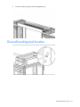
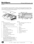
HP 10000 G2 Series Rack Options
Installation Guide
Abstract
This document is for the person who installs racks and rack products. This procedure is performed only by trained personnel. HP assumes you are
qualified in performing installations and trained in recognizing hazards in rack products.
Part Number: 489899-006
October 2013
Edition: 6
© Copyright 2008, 2013 Hewlett-Packard Development Company, L.P.
The information contained herein is subject to change without notice. The only warranties for HP products and services are set forth in the express
warranty statements accompanying such products and services. Nothing herein should be construed as constituting an additional warranty. HP shall
not be liable for technical or editorial errors or omissions contained herein.
Contents
About this guide ........................................................................................................................... 7
Rack options installation guide .................................................................................................................... 7
Important safety information........................................................................................................................ 7
Additional rack considerations .................................................................................................................... 7
Rack options ................................................................................................................................ 9
Ordering rack options................................................................................................................................ 9
100 Kilo Sliding Shelf kit ............................................................................................................. 11
About this device..................................................................................................................................... 11
Kit contents ................................................................................................................................... 11
Required tools ............................................................................................................................... 11
Preparing the sliding shelf rail assemblies for installation .............................................................................. 11
Installing the sliding shelf rail assemblies .................................................................................................... 12
Installing the sliding shelf .......................................................................................................................... 14
Using the 100 Kilo Sliding Shelf ................................................................................................................ 16
Airflow Optimization kit .............................................................................................................. 17
About this device..................................................................................................................................... 17
Kit contents ................................................................................................................................... 17
Required tools ............................................................................................................................... 17
Installing foam rail gaskets ....................................................................................................................... 17
Installing foam rail gaskets between racks......................................................................................... 18
Installing the floor gasket .......................................................................................................................... 20
Ballast kit ................................................................................................................................... 22
About this device..................................................................................................................................... 22
Kit contents ................................................................................................................................... 22
Required tools ............................................................................................................................... 22
Installing the ballast kit ............................................................................................................................. 22
Baying kit .................................................................................................................................. 25
About this device..................................................................................................................................... 25
Kit contents ................................................................................................................................... 25
Required tool ................................................................................................................................ 25
Installing the baying kit ............................................................................................................................ 25
Cable Management Bracket kit .................................................................................................... 28
About this device..................................................................................................................................... 28
Kit contents ................................................................................................................................... 28
Required tools ............................................................................................................................... 28
Installing the 1U cable management bracket ............................................................................................... 29
Installing the 2U cable management bracket ............................................................................................... 30
Installing the cable management D-ring bracket ........................................................................................... 30
Front mount .................................................................................................................................. 31
Side mount ................................................................................................................................... 32
Installing the cross-over bracket ................................................................................................................. 32
Installing the hook-and-loop cabling straps .................................................................................................. 34
Contents
3
Cable Management Tray kit ......................................................................................................... 36
About this device..................................................................................................................................... 36
Kit contents ................................................................................................................................... 36
Required tool ................................................................................................................................ 36
Installing the cable management tray ......................................................................................................... 37
Installing the cable management inner and outer trays ................................................................................. 39
Ground bonding stud location .................................................................................................................. 41
Fan (110V/220V) kit .................................................................................................................. 42
About this device..................................................................................................................................... 42
Kit contents ................................................................................................................................... 42
Required tools ............................................................................................................................... 42
Installing the fan ...................................................................................................................................... 42
Filler Panel kit ............................................................................................................................. 45
About this device..................................................................................................................................... 45
Kit contents ................................................................................................................................... 45
Required tools ............................................................................................................................... 45
Installing the filler panel ........................................................................................................................... 45
Front Door kit ............................................................................................................................. 46
About this device..................................................................................................................................... 46
Kit contents ................................................................................................................................... 46
Required tools ............................................................................................................................... 46
Installing the hinge brackets and lock catches ............................................................................................. 47
Installing the front door ............................................................................................................................ 48
Ground Bonding kit..................................................................................................................... 49
About this device..................................................................................................................................... 49
Kit contents ................................................................................................................................... 49
Required tools ............................................................................................................................... 49
Installing the ground bonding rack option kit on HP 10000 G2 Series Racks .................................................. 49
Installing the ground bonding rack option kit on HP 10000 G2 Series Rack side panels ......................... 55
Installing the ground bonding rack option kit on HP 10000 G2 Series Rack fan kits ............................... 57
Installing the ground bonding rack option kit on HP 10000 G2 Series Rack 150-mm extension kits ......... 59
Installing the ground bonding rack option kit on HP 10000 G2 Series Rack 200-mm extension kits ......... 59
Installing the ground bonding rack option kit on HP 10000 Series Racks ........................................................ 62
Installing the ground bonding rack option kit on HP 10000 Series Rack side panels .............................. 67
Installing the ground bonding rack option kit on HP 10000 Series Rack fan kits .................................... 67
Heavy Duty Stabilizer kit ............................................................................................................. 69
About this device..................................................................................................................................... 69
Kit contents ................................................................................................................................... 69
Required tools ............................................................................................................................... 69
Installing the rack stabilizer option kit......................................................................................................... 69
Hook-and-Loop Cabling Strap Clip kit ........................................................................................... 72
About this device..................................................................................................................................... 72
Kit contents ................................................................................................................................... 72
Required tools ............................................................................................................................... 72
Installing the hook-and-loop cabling strap clips ............................................................................................ 73
Light kit ...................................................................................................................................... 76
About this device..................................................................................................................................... 76
Kit contents ................................................................................................................................... 76
Required Tool ............................................................................................................................... 76
Contents
4
Important safety information...................................................................................................................... 76
Installing the 110V/220V Light ................................................................................................................. 77
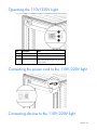
Operating the 110V/220V Light ............................................................................................................... 79
Connecting the power cord to the 110V/220V light .................................................................................... 79
Connecting devices to the 110V/220V light ............................................................................................... 79
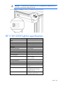
HP 110V/220V light kit specifications ....................................................................................................... 80
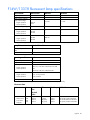
F14W/133-T8 fluorescent lamp specifications ............................................................................................ 81
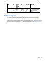
Material disposal .................................................................................................................................... 82
Mini Stabilizer kit........................................................................................................................ 83
About this device..................................................................................................................................... 83
Kit contents ................................................................................................................................... 83
Required tools ............................................................................................................................... 83
Installing the stabilizer ............................................................................................................................. 83
Rack Air Duct kit ......................................................................................................................... 86
About this kit .......................................................................................................................................... 86
Kit contents ................................................................................................................................... 86
Required tools ............................................................................................................................... 87
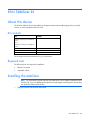
Installation video ..................................................................................................................................... 88
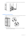
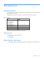
Installing the Top Exhaust Retrofit kit........................................................................................................... 88
Removing the rear doors ................................................................................................................ 88
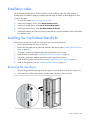
Installing the solid rack top plate ..................................................................................................... 89
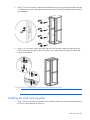
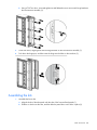
Installing the solid rack base plate ................................................................................................... 90
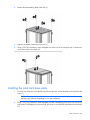
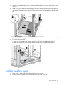
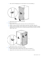
Installing the airflow gasket ............................................................................................................. 91
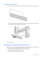
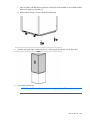
Installing the floor gasket ................................................................................................................ 93
Installing the Top Exhaust Extension kit ....................................................................................................... 93
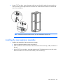
Removing the rear doors ................................................................................................................ 94
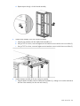
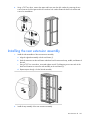
Installing the rear extension assembly ............................................................................................... 95
Installing the solid rear doors .......................................................................................................... 97
Assembling the kits ........................................................................................................................ 98
Installing the kit assembly ............................................................................................................. 101
Adjusting the kit .......................................................................................................................... 102
Baying options ...................................................................................................................................... 103
Rear Extension kit ..................................................................................................................... 105
About this device................................................................................................................................... 105
Kit contents ................................................................................................................................. 105
Required tools ............................................................................................................................. 105
Removing the rear doors ........................................................................................................................ 105
Installing the rear extension assembly....................................................................................................... 107
Installing the rear doors.......................................................................................................................... 109
Installing the cable management brackets ................................................................................................. 110
Server/Utility Shelf kit ................................................................................................................ 112
About this device................................................................................................................................... 112
Kit contents ................................................................................................................................. 112
Required tools ............................................................................................................................. 112
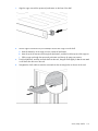
Installing the server/utility shelf ............................................................................................................... 112
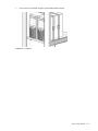
Side Panel kit ........................................................................................................................... 116
About this device................................................................................................................................... 116
Kit contents ................................................................................................................................. 116
Required tools ............................................................................................................................. 116
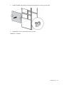
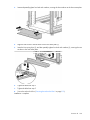
Installing the side panels ........................................................................................................................ 117
Contents
5
Tie-Down kit ............................................................................................................................. 119
About this device................................................................................................................................... 119
Required tools ............................................................................................................................. 119
Kit contents ................................................................................................................................. 119
Installing the tie-down kit .............................................................................................................. 119
Securing the rack to the floor ........................................................................................................ 121
1200 mm Full Frame Rack Tie-down Kit.................................................................................................... 121
Required tools ............................................................................................................................. 121
1200 mm full frame rack tie-down kit contents ................................................................................. 121
Installing the 1200 mm full frame rack tie-down kit .......................................................................... 121
Securing the 1200 mm full frame rack to the floor ........................................................................... 123
Vertical PDU Mounting kit .......................................................................................................... 124
About this device................................................................................................................................... 124
Kit contents ................................................................................................................................. 124
Required tools ............................................................................................................................. 124
Installing the Vertical PDU Mounting kit .................................................................................................... 124
Electrostatic discharge ............................................................................................................... 126
Preventing electrostatic discharge ............................................................................................................ 126
Grounding methods to prevent electrostatic discharge ................................................................................ 126
Support and other resources ...................................................................................................... 127
Before you contact HP............................................................................................................................ 127
HP contact information ........................................................................................................................... 127
Acronyms and abbreviations ...................................................................................................... 128
Documentation feedback ........................................................................................................... 129
Contents
6
About this guide
Rack options installation guide
This installation guide includes the instructions for installing rack option kits that are compatible with the HP
10000 G2 Series Rack.
For more information, see the HP 10000 G2 Series Rack User Guide on the HP website
(http://www.hp.com/go/rackandpower).
Important safety information
WARNING: To reduce the risk of personal injury or damage to the equipment, be sure that:
• The rear leveling feet are extended to the floor.
• The full weight of the rack rests on the rear leveling feet and front stabilizer feet.
WARNING: To reduce the risk of personal injury or damage to the rack and equipment, the
racks must be positioned and secured together according to these instructions. Failure to do so
could result in an unstable installation.
WARNING: Components can be very heavy. To reduce the risk of personal injury or damage to
the equipment:
• Remove all pluggable power supplies and modules to reduce the weight of the product before
lifting it.
• Observe local occupational health and safety requirements and guidelines for manual
material handling.
• Get help to lift and stabilize the product during installation or removal, especially when the
product is not fastened to the rails. When the component weighs more than 22.5 kg (50 lb),
at least two people must lift the component into the rack together. If the component is loaded
into the rack above chest level, a third person must assist in aligning the rails while the other
two support the component.
• Use caution when installing the component in or removing the component from the rack; it is
unstable when not fastened to the rails.
Additional rack considerations
Consider the following specifications and components, with regard to your specific rack configuration:
•
Power—If a UPS is installed, do not exceed its output rating. Be sure to review the installation
instructions provided with each component for important cautions and warnings.
•
PDUs—Install PDUs before installing other components.
•
Height—The height of the rack and of rack-mountable components is measured in U increments, where
U = 4.5 cm (1.75 in). When you are configuring your rack installation, remember that the total U
measurement of the components you want to install cannot exceed the stated U height of the rack.
About this guide
7
•
Keyboard—The rack keyboard requires installation of a 1U keyboard drawer rack option kit.
•
Monitor—The monitor requires installation of a monitor/utility shelf rack option kit unless you are using
a rack-mountable flat-panel monitor.
•
Server console switch—If a console switch is configured, use the CPU-to-console switch cable included
with the server. The standard distance between the console switch and the keyboard, monitor, and
mouse can vary by 3-, 7-, 12-, 20-, and 40-ft lengths.
NOTE: National electrical regulations governing the installation of building wiring require that
an appropriate cable, meeting fire-safety standards, must be used any time cabling is routed:
•
•
•
•
Through an overhead drop-ceiling
Under raised flooring
From room to room
From floor to floor
Be sure that the cable jacket or sleeving is made of material that does not burn easily and does not
exude toxic fumes when exposed to heat. Be sure that the cable you have selected is appropriate
for your installation site. If you require a U.S. plenum-rated (CL2P) cable, contact your local HP
authorized reseller to obtain any of the following options:
• 149363-B21-20-foot plenum cable
• 149364-B21-40-foot plenum cable
•
Rack baying option kits—The number of baying kits needed to join a series of racks is one less than the
number of racks in the suite. Each baying kit supplies parts to bay two cabinets on 600 mm (24 in)
center line spacing.
•
Side panels—Only one set of side panels is required for each row of bayed racks.
•
Stabilizer kit—A stabilizer kit is either required or recommended, depending on your rack
configuration. There are four stabilizer kit options.
o
The standard 600-mm (23.6 in) or 800-mm (31.5 in) front foot is required with deployments of
stand-alone racks. Rack rows with four or more bayed racks, without a single rack-mountable
component exceeding 99.8 kg (220 lb), do not need a stabilizer kit installed.
o
The heavy duty 600-mm (23.6 in) or 800-mm (31.5 in) front foot is required when a single
rack-mountable component weighing 99.8 kg (220 lb) or more is installed in a stand-alone rack or
in a rack belonging to a rack row of three or fewer bayed racks.
About this guide
8
Rack options
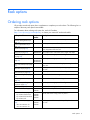
Ordering rack options
HP provides several rack option kits to complement or complete your rack solution. The following list is a
sample of the many rack option kits available.
For information about ordering rack option kits, see the HP website
(http://www.hp.com/go/rackandpower), or contact your nearest HP authorized reseller.
Rack option kit
Part
number
Description
100 Kilo Sliding Shelf kit (on
page 11)
234672-B21 Enables easy access to various rack components
Airflow Optimization kit (on
page 17)
AF090A
Ballast kit (on page 22)
120672-B21 Provides rack stability when you install, remove, or access
heavy equipment within the rack
Baying kit (on page 25)
248929-B21 Joins multiple racks of the same series, height, and depth
Cable Management Bracket kit
(on page 28)
AF099A
Enables you to improve airflow of your rack
Enables you to manage your cable configurations
Cable Management Tray kit (on 383982-B21 Enables you to manage your cable configurations
383983-B21
page 36)
383984-B21
257414-B21
Enhances natural convection cooling by increasing the airflow
Fan (110V/220V) kit (on page
in the rack
42)
Filler Panel kit (on page 45)
AF072A
Enables you to control airflow by covering empty locations in
your rack
Front Door kit (on page 46)
AF009A
Enables you to add a door to the front of your rack
Ground Bonding kit (on page
49)
AF074A
Reduces the level of electromagnetic emissions outside the rack
Heavy Duty Stabilizer kit (on
page 69)
AF064A
Increases the stability of free-standing racks
Hook-and-Loop Cabling Strap
Clip kit (on page 72)
379820-B21 Enables you to manage your cable configurations
Light kit (on page 76)
361589-B21 Provides additional light inside your rack
Mini Stabilizer kit (on page 83) AF062A
AF066A
Increases the stability of free-standing racks
Rack Air Duct kit (on page 86)
Removes warm air from the rack by channeling the warm air
into the data center ceiling return air plenum
•
•
•
Top exhaust extension kit
Top exhaust field retrofit kit
Top exhaust rack
Rear Extension kit (on page
105)
•
•
42U rear extension kit
47U rear extension kit
AF028A
AF029A
AF030A
AF036A
AF043A
Enables you to add 200-mm (7.87 in) of depth to the rear of
your rack
Rack options
9
Rack option kit
Part
number
Description
Server/Utility Shelf kit (on page 253449-B21 Holds rack components inside the rack
112)
AF054A
Provides enclosures for the sides of a rack
Side Panel kit (on page 116)
Tie-Down kit (on page 119)
AF076A
Increases the stability of free-standing racks
Vertical PDU Mounting kit (on
page 124)
H6L32A
Allows HP PDU vertical models to be mounted in the rack
Rack options
10
100 Kilo Sliding Shelf kit
About this device
The HP 100 Kilo Sliding Shelf kit enables you to install a sliding shelf in your rack mount system for placement
and easy access to various components. This option occupies 2Us of rack space.
Kit contents
Item
Quantity
Shelf with handle
1
Right rail with fixed brackets
1
Left rail with fixed brackets
1
Sliding rail
2
Cable management arm with
hardware
1
Rack template
1
Hardware kit
•
•
•
•
•
•
•
M4
M4
M4
M6
M4
M4
M6
x 12 flat HD screw
external washer
x 10 pan HD screw
x 12 pan HD screw
plain washer
nut
external washer
•
•
•
•
•
•
•
8
8
2
12
2
6
10
Extra hardware might be included for your convenience.
Required tools
The following tools are required for installation:
•
No. 2 Phillips screwdriver
•
No. 3 Phillips screwdriver
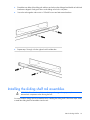
Preparing the sliding shelf rail assemblies for
installation
Each sliding shelf rail assembly consists of a rail with fixed brackets attached to a sliding rail. To construct the
sliding shelf rail assemblies:
1.
Hold the flat side of the left rail with fixed brackets facing toward you.
2.
Place the sliding rail on top of the left rail with fixed brackets.
100 Kilo Sliding Shelf kit 11
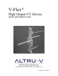
3.
Extend the inner slides of the sliding rail until the screw holes on the sliding rail and the left rail with fixed
brackets are aligned. Gently push down on the sliding rail to lock it into place.
4.
Secure the rails together with two M4 x 12 flat HD screws and M4 external washers.
5.
Repeat steps 1 through 4 for the right rail with fixed brackets.
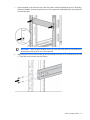
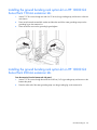
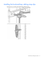
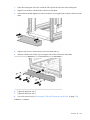
Installing the sliding shelf rail assemblies
WARNING: To reduce the risk of personal injury or damage to the equipment, be sure to secure
mounted rack components when moving the rack.
You must install the sliding shelf rail assemblies before installing the sliding shelf. Follow these steps closely
to install the sliding shelf rail assemblies into the rack:
100 Kilo Sliding Shelf kit 12
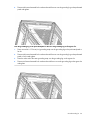
1.
Use the template on the front and rear of the rack frame to mark the attachment points for the sliding
shelf rail assemblies, by measuring from the top of the component installed below the desired position
for the sliding shelf.
IMPORTANT: When using the template on the rear of the rack frame, mark the rack at the top of
the template to help align the next rack component.
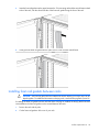
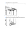
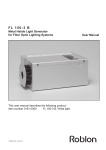
2.
Align and secure the rear of the left sliding shelf rail assembly to the rear of the rack frame with two M6
x 12 pan HD screws and M6 external washers.
100 Kilo Sliding Shelf kit 13
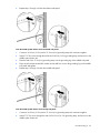
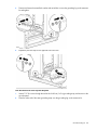
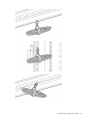
3.
Secure the front of the left sliding shelf rail assembly to the front of the rack frame with two M6 x 12 pan
HD screws and M6 external washers.
4.
Repeat steps 2 and 3 to install the right sliding shelf rail assembly.
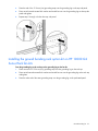
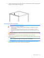
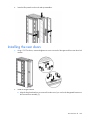
Installing the sliding shelf
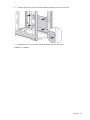
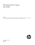
1.
Move the sliding shelf into the rack while tilting the front of the shelf up. Align the rear notches on the
sliding shelf over the rear tabs on the sliding shelf rail assemblies.
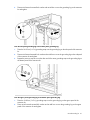
2.
Push the sliding shelf down onto the rear tabs to align the front notches on the sliding shelf with the front
tabs on the sliding shelf rail assemblies.
3.
Lower the front of the sliding shelf over the tabs on the front of the sliding shelf rail assemblies and push
down gently to lock the shelf into place.
100 Kilo Sliding Shelf kit 14
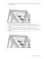
4.
Secure the sliding shelf to each sliding rail using one M4 x 12 flat HD screw and M4 external washer
with one M4 nut on the inside of the shelf.
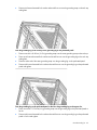
5.
Attach the cable management arm to the sliding shelf with the flat side of the cable management arm
mounting bracket flush with the sliding shelf.
6.
Secure the cable management arm to the sliding shelf using two M4 x 12 flat HD screws and M4
external washers with two M4 nuts on the inside of the shelf.
NOTE: The cable management arm attaches to the rear of the sliding shelf on either the right or
left side.
100 Kilo Sliding Shelf kit
15
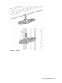
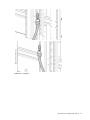
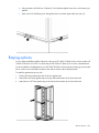
7.
Secure the opposite end of the cable management arm to the rack using two M6 x 12 pan HD screws
and M6 external washers.
Installation is complete.
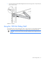
Using the 100 Kilo Sliding Shelf
Use the handle on the front of the sliding shelf to slide it in and out of the rack. When sliding the shelf back
into the rack, there may be resistance. Apply pressure as needed to fully move the shelf into the rack.
IMPORTANT: Be sure to secure all rack mount system components when moving the shelf out of
the rack.
100 Kilo Sliding Shelf kit 16
Airflow Optimization kit
About this device
The HP Airflow Optimization kit enables you to install foam rail gaskets in your HP 10000 G2 Series 22U,
36U, 42U, and 47U 600-mm (24-in) wide racks and in to 42U 800-mm (31-in) wide racks to improve
separation between hot and cold aisles in the data center.
Kit contents
Item
Quantity
600-mm (24-in) perforated floor
gasket
—or—
800-mm (31-in) perforated floor
gasket
1
Foam rail gasket roll
4
1
Extra hardware might be included for your convenience.
Required tools
No tools are required for this procedure.
Installing foam rail gaskets
IMPORTANT: This option kit is only compatible with HP racks that are 600-mm (24 in) or
800-mm (31 in) wide.
1.
Cut the foam rail gasket to fit the size of your rack.
2.
Insert the foam rail gasket into the rack front door on both sides of the rack.
Airflow Optimization kit
17
3.
Insert the foam rail gasket into the space between the 19-in mounting rails and the vertical frame on both
sides of the rack, with the closed cell side of the foam rail gasket facing the front of the rack.
4.
Gently push the foam rail gasket into the space until it is flush with the vertical frame.
Installing foam rail gaskets between racks
CAUTION: The foam rail gasket must be installed into the rack before two or more racks can be
bayed together. For additional information on baying racks, see the HP Baying Rack Option Kit.
If installing the foam rail gasket between racks that have a baying kit installed, the baying bracket must be
removed before the foam rail gasket can be inserted between the racks.
1.
Position the racks side by side.
2.
Cut the foam rail gasket to fit the size of your rack.
Airflow Optimization kit
18
3.
Insert the foam rail gasket into the space between the racks with the closed cell side of the foam rail
gasket facing the front of the rack.
NOTE: Follow steps 1 through 3 to install the foam rail gasket into a rack that will be bayed using
a 24-in. baying bracket.
If the rack will be bayed using a 600-mm baying bracket, rotate the foam rail gasket 90 degrees
before inserting it into the space between the racks.
4.
Gently push the foam rail gasket into the space between the racks until it is flush with the vertical frame.
Airflow Optimization kit
19
5.
(Optional) See the HP Baying Rack Option Kit for specific information on baying racks.
Installing the floor gasket
1.
Depending on the size of your rack, cut the floor gasket at the perforation to reduce the length from
800-mm (31 in) to 600-mm (24 in).
Airflow Optimization kit
20
2.
Remove the protective tape from the bottom edge of the floor gasket, and apply it to the bottom of the
rack with the adhesive strip facing the front of the rack.
Installation is complete.
Airflow Optimization kit
21
Ballast kit
About this device
The HP Ballast kit provides additional stability with single-rack installations.
Kit contents
Item
Quantity
Ballast assembly
2
M6 screws
10
Cage nuts
10
Extra hardware might be included for your convenience.
Required tools
The following tools are required for installation:
•
Cage nut insertion tool (included in your original rack hardware kit)
•
One of the following screwdrivers:
o
Flathead screwdriver
o
T-25 Torx driver
Installing the ballast kit
HP recommends installing a single ballast assembly as close to the bottom of the rack as possible.
Occasionally, more than one ballast kit might be necessary. In these cases, install the first ballast assembly
as close to the bottom of the rack as possible and move up the rack accordingly.
CAUTION: To reduce the risk of personal injury or damage to the equipment, HP recommends
that you install the HP Ballast kit only in unconfigured racks.
Ballast kit 22
1.
Install the two bottom cage nuts using the cage nut insertion tool included in your original rack
hardware kit.
2.
Count 16 holes up the rack, starting at the bottom cage nuts, and install the two top cage nuts using the
cage nut insertion tool.
3.
Align the screw holes of the ballast assembly with the installed cage nuts.
Ballast kit 23
4.
Insert the M6 screws into one side of the ballast assembly to secure it to the rack.
5.
Repeat step 4 to secure the other side of the ballast assembly to the rack.
Installation is complete.
Ballast kit 24
Baying kit
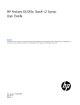
About this device
The HP Baying kit enables you to connect multiple racks of the same series (HP 10000 and 10000 G2 Series
Racks), height, and depth. For example, two HP 10622 Racks can be bayed together, as well as two HP
10842 Racks.
Kit contents
Item
Quantity
24-inch baying brackets
6
600-mm baying brackets
6
T-30 Torx screws
15
Extra hardware might be included for your convenience.
Required tool
You will need a T-30 Torx driver.
Installing the baying kit
WARNING: To reduce the risk of personal injury or damage to the rack and equipment, the
racks must be positioned and secured together according to these instructions. Failure to do so
could result in an unstable installation.
NOTE: The appearance of the rack might vary depending on the model of the rack purchased.
Baying kit 25
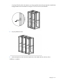
1.
Remove the front and rear doors.
2.
Remove the side panels (if present between the racks).
3.
Position the racks side by side, ensuring that the feet of the racks are on solid flooring (no cracks or
openings).
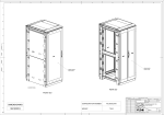
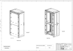
4.
Attach three baying brackets (either 24-inch or 600-mm depending on the floor layout) to the front and
rear of each rack set using two T-30 Torx screws in each bracket.
-or-
Baying kit 26
If you bay HP racks with a rear extension, you do not need to remove the rear extensions. Attach three
baying brackets to the rear extensions using two T-30 Torx screws in each bracket.
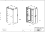
5.
Bay any additional racks.
6.
Attach side panels to each end of the bayed racks, and reattach the front and rear doors.
Installation is complete.
Baying kit 27
Cable Management Bracket kit
About this device
The HP Cable Management Bracket kit assists with cable management and is designed for use with all HP
racks.
Kit contents
Item
Quantity
1U cable management bracket
1
2U cable management bracket
1
Cable management D-ring bracket
clips
10
Cable management D-ring bracket
clamps
10
Cross-over brackets
2
12.7-cm (5-in) hook-and-loop cabling 10
strap
20.3-cm (8-in) hook-and-loop cabling 10
strap clips
M6 cage nuts
11
M6 x 16-mm Torx screws
11
M5.5-mm x 10-mm Torx screws
9
1/4 turn plastic latches
6
Extra hardware might be included for your convenience.
Required tools
The following tools are required for installation:
•
T-25 Torx driver
•
Cage nut insertion tool (included with your original rack hardware kit)
Cable Management Bracket kit
28
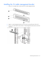
Installing the 1U cable management bracket
1.
Insert one 1/4 turn plastic latch on either side of the 1U cable management bracket.
2.
Align the 1U cable management bracket to the screw holes in the desired location of the rack (1).
3.
Turn the 1/4 turn plastic latch on either side of the 1U cable management bracket clockwise until it locks
in place (2).
Cable Management Bracket kit
29
Installing the 2U cable management bracket
1.
Insert two 1/4 turn plastic latches on either side of the 2U cable management bracket.
2.
Align the 2U cable management bracket to the screw holes in the desired location of the rack (1).
3.
Turn the two 1/4 turn plastic latches on either side of the 2U cable management bracket clockwise until
they lock in place (2).
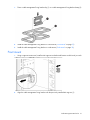
Installing the cable management D-ring bracket
The cable management D-ring bracket can be installed in either a front mount or a side mount, depending on
your rack configuration.
Cable Management Bracket kit
30
1.
Place a cable management D-ring bracket clip (1) on a cable management D-ring bracket clamp (2).
2.
Install the cable management D-ring bracket in a front mount ("Front mount" on page 31).
3.
Install the cable management D-ring bracket in a side mount ("Side mount" on page 32).
Front mount
1.
Using a cage nut insertion tool, install an M6 cage nut into the desired location on the front of your rack.
2.
Align the cable management D-ring bracket with the previously installed M6 cage nut (1).
Cable Management Bracket kit
31
3.
Using a T-25 Torx driver, insert one M6 x 16-mm Torx screw to secure the cable management D-ring
bracket to the rack (2).
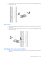
Side mount
1.
Align the cable management D-ring bracket with the screw hole in the desired location on the side of
your rack (1).
2.
Using a T-25 Torx driver, insert one M5.5 x10-mm Torx screw to secure the cable management D-ring
bracket to the rack (2).
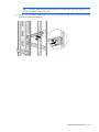
Installing the cross-over bracket
1.
Align the cross-over bracket with the appropriate screw holes in the desired location across the back of
the rack (1).
Cable Management Bracket kit
32
NOTE: The screw holes for the cross-over bracket are located on the side of the rear rack screw
column, towards the inside of the rack.
2.
Using a T-25 Torx driver, insert two M5.5 x 10-mm Torx screws on either side of the cross-over bracket
and secure to the rack frame (2).
Cable Management Bracket kit
33
Installing the hook-and-loop cabling straps
Attach the clip to the rack in any of the following positions, then route and secure your cables with the
hook-and-loop cabling straps.
Cable Management Bracket kit
34
Installation is complete.
Cable Management Bracket kit
35
Cable Management Tray kit
About this device
The HP Cable Management Tray kit enables you to attach cable management trays to the top of HP racks to
improve cable management.
Kit contents
Depending on which kit you order, this kit includes the following items:
Item
Quantity
600-mm cable management tray
1
600-mm cable trough
8
Wire for trough
16
Cover
8
—or—
Item
Quantity
800-mm cable management tray
1
800-mm cable trough
1
Wire for trough
2
Cover
1
—or—
Item
Quantity
Cable trough inner tray
1
Cable trough outer tray
1
Extra hardware might be included for your convenience.
Required tool
You will need a T-30 Torx driver.
Cable Management Tray kit
36
Installing the cable management tray
1.
Attach the wire for the trough to the cable management tray.
2.
Remove the two screws from the rack top.
Cable Management Tray kit
37
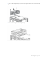
3.
Install the cable management tray on top of the rack, using the same two screws you removed in step
2.
4.
Route the cables through the cable management tray.
Cable Management Tray kit
38
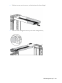
5.
Hook and slide the cover into place.
Installing the cable management inner and outer trays
1.
Attach the cable management outer tray to the cable management tray.
Cable Management Tray kit
39
2.
Slide the inner tray into the outer tray, and adjust them to the desired length.
3.
Attach the cable management inner tray to the cable management tray.
Cable Management Tray kit
40
4.
Route the cables through the cable management tray.
Ground bonding stud location
Cable Management Tray kit
41
Fan (110V/220V) kit
About this device
The HP Fan (110V/220V) kit enhances the natural convection cooling by increasing rack airflow.
Kit contents
Item
Quantity
Fan assembly
1
Power cord
2
Cable fastener
4
This kit might contain extra hardware for your convenience.
Required tools
You will need a T-30 Torx driver.
Installing the fan
NOTE: The rack top covers might be different, but the installations are identical.
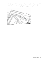
1.
Using a T-30 Torx driver, remove the four T-30 Torx screws securing the rack top cover to the rack, and
remove the rack top cover. Retain the screws.
2.
Align the fan assembly so that the power cord faces the rear of the rack.
Fan (110V/220V) kit
42
3.
Insert the fan assembly into the top of the rack and secure using the four T-30 Torx screws from step 1.
4.
Connect the power cord to the fan assembly.
Fan (110V/220V) kit
43
5.
Insert the notched end of the tie wrap into a small hole in the rack rail and push the tie wrap in to lock
it in place. Encircle the power cord with the tie wrap by inserting the free end of the tie wrap into the
hole on the other end of the tie wrap, pulling the tie wrap tight, and cutting off excess length.
Installation is complete.
Fan (110V/220V) kit
44
Filler Panel kit
About this device
The HP Filler Panel kit enables you to cover open areas of the rack to better control airflow.
Kit contents
Item
Quantity
1U Filler panels
—or—
1U Filler panels
10
100
This kit might contain extra hardware for your convenience.
Required tools
No tools are required for this procedure.
Installing the filler panel
1.
Position the filler panel in the desired rack location.
2.
Snap the filler panel into place.
CAUTION: Always use filler panels to fill all remaining empty front panel U-spaces in the rack.
This arrangement ensures proper airflow. Using a rack without filler panels results in improper
cooling, which can lead to thermal damage.
Filler Panel kit
45
Front Door kit
About this device
The HP Front Door kit enables you to add a front door to your HP 10000 G2 Series rack. You can also install
this option kit on HP 10000 series racks of the same size.
Kit contents
Item
Quantity
Front door
1
Keys
2
Hinge brackets
2
Lock catches
2
This kit might contain extra hardware for your convenience.
Required tools
The following tools are required for installation:
•
T-25 Torx driver
•
Phillips screwdriver
Front Door kit
46
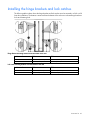
Installing the hinge brackets and lock catches
The following tables indicate where the hinge brackets and lock catches are to be mounted in a 36U or 42U
front door installation. The distance is measured from the bottom of the rack to an indicated hinge bracket or
lock catch fastening hole.
Hinge bracket mounting distance from the bottom of the rack
Position number
36U
42U
1
1598.5 mm (62.9 in)
1856 mm (73.1 in)
2
98.5 mm (3.9 in)
98.5 mm (3.9 in)
Lock catch mounting distance from the bottom of the rack
Position number
36U
42U
3
569.5 mm (22.4 in)
698.5 mm (27.5 in)
4
1127.5 mm (44.4 in)
1256.5 mm (49.5 in)
Front Door kit
47
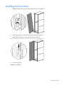
Installing the front door
1.
Slide the bottom door hinge onto the hinge bracket on the rack frame.
2.
Lift the top hinge pin up, and slide the upper door hinge into place.
3.
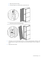
Release the top hinge pin to secure the front door to the rack.
4.
Close the front door.
Installation is complete.
Front Door kit
48
Ground Bonding kit
About this device
The HP Ground Bonding kit reduces the electromagnetic emissions outside the rack. These emissions are
produced during normal operation of the electronic components within the rack. Typically, rack-mounted
equipment must meet class A emissions levels, but you might want to reduce these levels even further. Use this
kit to tie all the conductive structural components together with conductive cables, and then attach the kit to
a ground bonding point on the AC power distribution device of the rack or the building ground.
Kit contents
Item
Quantity
15.24-cm (6-in) grounding straps
6
15.24-cm (6-in) grounding straps
(with a connector on one end)
6
36.83-cm (14.5-in) grounding straps 8
36.83-cm (14.5-in) grounding straps 6
(with a connector on one end)
M8 internal serrated lock washer
20
M8 hex nut
20
M5.5 T-25 Torx screw
12
M6 x 10-mm Torx screw
1
M8 x 20-mm bolt
1
M8 Belleville toothed washer
1
M5 Belleville toothed washer
1
This kit might contain extra hardware for your convenience.
Required tools
The following tools are required for installation:
•
T-25 Torx driver
•
M8 socket
Installing the ground bonding rack option kit on HP
10000 G2 Series Racks
Attach the appropriate grounding straps to the following locations:
From the system chassis to the front door (without a grounding lug):
1.
Remove the rack front door.
Ground Bonding kit 49
a. Unlock and open the front door.
b. Lift the top hinge pin up, and tilt the door away from the rack.
c.
Lift the door up and out of the bottom hinge.
2.
Insert an M6 T-25 Torx screw through one end of a 15.24-cm (6-in) grounding strap, and insert it in the
second hole below the upper front door hinge on the vertical frame member of the rack. Tighten the
screw.
3.
Replace the rack front door.
Ground Bonding kit 50
4.
Insert a T-25 Torx screw through the other end of the same grounding strap, and insert it in the hole on
the rack front door. Tighten the screw.
From the system chassis rail to the front door (with a grounding lug):
1.
Insert a T-25 Torx screw through one end of a 36.83-cm (14.5-in) grounding strap, and secure it to the
system chassis rail.
2.
Place the other end of the same grounding strap over the grounding lug on the front door.
3.
Place an M8 internal serrated lock washer and an M8 hex nut over the grounding lug on the front door
and tighten.
From the system chassis rail to the right rear door:
1.
Insert a T-25 Torx screw through the end of a 36.83-cm (14.5-in) grounding strap, and secure it to the
system chassis rail.
2.
Place the other end of the same grounding strap over the grounding lug on the right rear door.
Ground Bonding kit 51
3.
Place an M8 internal serrated lock washer and an M8 hex nut over the grounding lug on the right rear
door and tighten.
From the system chassis rail to the left rear door:
1.
Insert a T-25 Torx screw through the end of a 36.83-cm (14.5-in) grounding strap, and secure it to the
system chassis rail.
2.
Place the other end of the grounding strap over the grounding lug on the left rear door.
3.
Place an M8 internal serrated lock washer and an M8 hex nut over the grounding lug on the left rear
door and tighten.
From the left rear door to the left rear door cable access panel:
1.
Place one end of a 15.24-cm (6-in) grounding strap over the grounding lug on the left rear door.
2.
Place an M8 internal serrated lock washer and an M8 hex nut over the grounding lug on the left rear
door and tighten.
3.
Place the other end of the same grounding strap over the grounding lug on the cable access panel.
Ground Bonding kit 52
4.
Place an M8 internal serrated lock washer and an M8 hex nut over the grounding lug on the cable
access panel and tighten.
From the system chassis rail to the rack top:
1.
Insert a T-25 Torx screw through one end of a 15.24-cm (6-in) grounding strap, and secure it to the
system chassis rail.
2.
Place the other end of the same grounding strap over the grounding lug on the rack top.
3.
Place an M8 internal serrated lock washer and an M8 hex nut over the grounding lug on the rack top
and tighten.
From the grounding lug on the rack top to the grounding lug on the perforated panel:
1.
Place one end of a 36.83-cm (14.5-in) grounding strap over the grounding lug on the rack top.
2.
Place an M8 internal serrated lock washer and an M8 hex nut over the grounding lug on the rack top
and tighten.
3.
Place the other end of the same grounding strap over the grounding lug on the perforated panel.
Ground Bonding kit 53
4.
Place an M8 internal serrated lock washer and an M8 hex nut over the grounding lug on the perforated
panel and tighten.
From the grounding lug on the perforated panel or fan kit to the grounding lug on the egress slot:
1.
Place one end of a 15.24-cm (6-in) grounding strap over the grounding lug on the perforated panel or
fan kit.
2.
Place an M8 internal serrated lock washer and an M8 hex nut over the grounding lug on the perforated
panel or fan kit and tighten.
3.
Place the other end of the same grounding strap over the grounding lug on the egress slot.
4.
Place an M8 internal serrated lock washer and an M8 hex nut over the grounding lug on the egress slot
and tighten.
Ground Bonding kit 54
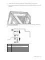
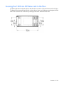
From the rack to a building facility, contact your building supervisor for more information. The following
figure illustrates parts for this step.
Reference
Item
1
48.26-cm (19-in) mounting rail (the mounting hole is
located at the top or bottom of the rail)
2
M8 hex nut
3
M8 Belleville toothed washer
4
Facility ground (not included with this kit)
5
M8 x 20 bolt
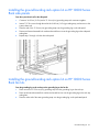
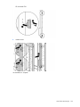
Installing the ground bonding rack option kit on HP 10000 G2
Series Rack side panels
From the middle system chassis rail to the bottom side panel:
1.
Connect a 36.83-cm (14.5-in) and a 15.24-cm (6-in) grounding strap with connectors together.
2.
Insert a T-25 Torx screw through the end of the 36.83-cm (14.5-in) grounding strap, and secure it to the
middle system chassis rail.
3.
Place the end of the 15.24-cm (6-in) grounding strap over the grounding lug on the bottom side panel.
4.
Place an M8 internal serrated lock washer and an M8 hex nut over the grounding lug on the bottom
side panel and tighten.
Ground Bonding kit 55
5.
Repeat steps 1 through 4 for the other bottom side panel.
From the middle system chassis rail to the middle side panel:
1.
Connect a 36.83-cm (14.5-in) and a 15.24-cm (6-in) grounding strap with connectors together.
2.
Insert a T-25 Torx screw through the end of the 36.83-cm (14.5-in) grounding strap, and secure it to the
middle system chassis rail.
3.
Place the end of the 15.24 (6-in) grounding strap over the grounding lug on the middle side panel.
4.
Place an M8 internal serrated lock washer and an M8 hex nut over the grounding lug on the middle
side panel and tighten.
5.
Repeat steps 1 through 4 for the other middle side panel.
From the middle system chassis rail to the top side panel:
1.
Connect a 36.83-cm (14.5-in) and a 15.24-cm (6-in) grounding strap with connectors together.
2.
Insert a T-25 Torx screw through the end of a 36.83-cm (14.5-in) grounding strap, and secure it to the
middle system chassis rail.
Ground Bonding kit 56
3.
Place the end of the 15.24-cm (6-in) grounding strap over the grounding lug on the top side panel.
4.
Place an M8 internal serrated lock washer and an M8 hex nut over the grounding lug on the top side
panel and tighten.
5.
Repeat steps 1 through 4 for the other top side panel.
Installing the ground bonding rack option kit on HP 10000 G2
Series Rack fan kits
From the grounding lug on the rack top to the grounding lug on the fan kit:
1.
Place one end of a 15.24-cm (6-in) grounding strap over the grounding lug on the rack top.
2.
Place an M8 internal serrated lock washer and an M8 hex nut over the grounding lug on the rack top
and tighten.
3.
Place the other end of the same grounding strap over the grounding lug on the perforated panel.
Ground Bonding kit 57
4.
Place an M8 internal serrated lock washer and an M8 hex nut over the grounding lug on the perforated
panel and tighten.
From the grounding lug on the fan kit to the grounding lug on the egress slot:
1.
Place one end of a 36.83-cm (14.5-in) grounding strap over the grounding lug on the fan kit.
2.
Place an M8 internal serrated lock washer and an M8 hex nut over the grounding lug on the fan kit and
tighten.
3.
Place the other end of the same grounding strap over the grounding lug on the egress slot.
4.
Place an M8 internal serrated lock washer and an M8 hex nut over the grounding lug on the egress slot
and tighten.
Ground Bonding kit 58
Installing the ground bonding rack option kit on HP 10000 G2
Series Rack 150-mm extension kits
1.
Insert a T-25 Torx screw through one end of a 15.24-cm (6-in) grounding strap, and secure it to the rear
rack chassis.
2.
Place an M8 internal serrated lock washer and the other end of the same grounding strap over the
grounding lug on the extension kit.
3.
Place an M8 hex nut over the grounding lug and tighten.
Installing the ground bonding rack option kit on HP 10000 G2
Series Rack 200-mm extension kits
From the extension kit to the bottom rack side panel:
1.
Insert a T-25 Torx screw through the end of the 36.83-cm (14.5 in) grounding strap, and secure it to the
bottom side panel.
2.
Place the other end of the same grounding strap over the grounding lug on the extension kit.
Ground Bonding kit 59
3.
Place an M8 internal serrated lock washer and an M8 hex nut over the grounding lug on the extension
kit and tighten.
4.
Repeat the previous steps for the opposite side of the rack.
From the extension kit to the top rack side panel:
1.
Insert a T-25 Torx screw through the end of the 36.83-cm (14.5 in) grounding strap, and secure it to the
top side panel.
2.
Place the other end of the same grounding strap over the grounding lug on the extension kit.
Ground Bonding kit 60
3.
Place an M8 internal serrated lock washer and an M8 hex nut over the grounding lug on the extension
kit and tighten.
From the side panel grounding lug to the bottom panel grounding lug:
1.
Place the 36.83-cm (14.5 in) grounding strap over the grounding lug on the side panel of the extension
kit.
2.
Place an M8 internal serrated lock washer and an M8 hex nut over the grounding lug on the side panel
of the extension kit and tighten.
3.
Repeat the previous steps to secure the other end of the same grounding strap to the grounding lug on
the bottom panel of the extension kit.
From the egress panel grounding lug to the bottom panel grounding lug:
1.
Place the 36.83-cm (14.5 in) grounding strap over the grounding lug on the egress panel of the
extension kit.
2.
Place an M8 internal serrated lock washer and an M8 hex nut over the grounding lug on the egress
panel of the extension kit and tighten.
Ground Bonding kit
61
3.
Repeat the previous steps to secure the other end of the same grounding strap to the grounding lug on
the bottom panel of the extension kit.
Installing the ground bonding rack option kit on HP
10000 Series Racks
Attach the appropriate grounding straps to the following locations:
From the system chassis rail to the front door:
1.
Insert a T-25 Torx screw through one end of a 36.83-cm (14.5-in) grounding strap, and secure it to the
system chassis rail.
2.
Remove the inside front door panel screw.
3.
Place an M5 Belleville toothed washer and the other end of the grounding strap over the front door
panel screw.
Ground Bonding kit 62
4.
Reinsert and tighten the front door panel screw.
From the system chassis rail to the right rear door:
1.
Insert a T-25 Torx screw through the end of a 36.83-cm (14.5-in) grounding strap, and secure it to the
system chassis rail.
2.
Place the other end of the same grounding strap over the grounding lug on the right rear door.
3.
Place an M8 internal serrated lock washer and an M8 hex nut over the grounding lug on the right rear
door and tighten.
From the system chassis rail to the left rear door:
1.
Insert a T-25 Torx screw through the end of a 36.83-cm (14.5-in) grounding strap, and secure it to the
system chassis rail.
2.
Place the other end of the same grounding strap over the grounding lug on the left rear door.
Ground Bonding kit 63
3.
Place an M8 internal serrated lock washer and an M8 hex nut over the grounding lug on the left rear
door and tighten.
From the left rear door to the left rear door cable access panel:
1.
Place one end of a 15.24-cm (6-in) grounding strap over the same grounding lug on the left rear door.
2.
Place an M8 internal serrated lock washer and an M8 hex nut over the grounding lug on the left rear
door and tighten.
3.
Place the other end of the same grounding strap over the grounding lug on the cable access panel.
4.
Place an M8 internal serrated lock washer and an M8 hex nut over the grounding lug on the cable
access panel and tighten.
From the system chassis rail to the rack top:
1.
Insert a T-25 Torx screw through on end of a 15.24-cm (6-in) grounding strap and secure it to the system
chassis rail.
2.
Place the other end of the same grounding strap over the grounding lug on the rack top.
Ground Bonding kit 64
3.
Place an M8 internal serrated lock washer and an M8 hex nut over the grounding strap on the rack top
and tighten.
From the grounding lug on the rack top to the grounding lug on the perforated panel:
1.
Place one end of a 36.83-cm (14.5-in) grounding strap over the same grounding strap on the rack top.
2.
Place an M8 internal serrated lock washer and an M8 hex nut over the grounding lug on the rack top
and tighten.
3.
Place the other end of the same grounding strap over the grounding lug on the perforated panel.
4.
Place an M8 internal serrated lock washer and an M8 hex nut over the grounding lug on the perforated
panel and tighten.
From the grounding lug on the perforated panel or fan kit to the grounding lug on the egress slot:
1.
Place one end of a 15.24-cm (6-in) grounding strap over the grounding lug on the perforated panel or
fan kit.
2.
Place an M8 internal serrated lock washer and an M8 hex nut over the grounding lug on the perforated
panel or fan kit and tighten.
Ground Bonding kit 65
3.
Place the other end of the same grounding strap over the grounding lug on the egress slot.
4.
Place an M8 internal serrated lock washer and an M8 hex nut over the grounding lug on the egress slot
and tighten.
From the rack to a building facility, contact your building supervisor for more information. The following
figure illustrates parts for this step.
Reference
Item
1
48.26-cm (19-in) mounting rail (the mounting hole is
located at the top or bottom of the rail)
2
M8 hex nut
3
M8 Belleville toothed washer
4
Facility ground (not included with this kit)
5
M8 x 20 bolt
Ground Bonding kit 66
Installing the ground bonding rack option kit on HP 10000 Series
Rack side panels
From the system chassis rail to the side panel:
1.
Connect a 36.83-cm (14.5-in) and a 15.24-cm (6-in) grounding strap with connectors together.
2.
Insert a T-25 Torx screw through the end of the 36.83-cm (14.5-in) grounding strap, and secure it to the
system chassis rail.
3.
Place the end of the 15.24-cm (6-in) grounding strap over the grounding lug on the side panel.
4.
Place an M8 internal serrated lock washer and an M8 hex nut over the grounding lug on the side panel
and tighten.
5.
Repeat steps 1 through 4 for the other side panel.
Installing the ground bonding rack option kit on HP 10000 Series
Rack fan kits
From the grounding lug on the rack top to the grounding lug on the fan kit:
1.
Place one end of a 15.24-cm (6-in) grounding strap over the grounding lug on the rack top.
2.
Place an M8 internal serrated lock washer and an M8 hex nut over the grounding lug on the rack top
and tighten.
3.
Place the other end of the same grounding strap over the grounding lug on the perforated panel.
Ground Bonding kit 67
4.
Place an M8 internal serrated lock washer and an M8 hex nut over the grounding lug on the perforated
panel and tighten.
From the grounding lug on the fan kit to the grounding lug on the egress slot:
1.
Place one end of a 36.83-cm (14.5-in) grounding strap over the grounding lug on the fan kit.
2.
Place an M8 internal serrated lock washer and an M8 hex nut over the grounding lug on the fan kit and
tighten.
3.
Place the other end of the same grounding strap over the grounding lug on the egress slot.
4.
Place an M8 internal serrated lock washer and an M8 hex nut over the grounding lug on the egress slot
and tighten.
Ground Bonding kit 68
Heavy Duty Stabilizer kit
About this device
The HP Heavy Duty Stabilizer kit provides stability and support and prevents possible tipping when you
install, remove, or access equipment within the rack.
If you have a stand-alone rack with a single rack-mountable component that exceeds 99.8 kg (220 lb) or if
you have three or fewer bayed racks with a single rack-mountable component that exceeds 99.8 kg (220 lb),
you must use the heavy duty stabilizer.
Kit contents
Item
Quantity
Heavy duty front stabilizer mount
1
Heavy duty stabilizer feet
2
M8 x 16-mm bolt
8
M8 x 30-mm bolt
2
M8 flat washer
10
This kit might contain extra hardware for your convenience.
Required tools
The following tools are required for installation:
•
Ratchet with sockets
•
Adjustable wrench
Installing the rack stabilizer option kit
1.
Install the front stabilizer mount.
a. Align the front stabilizer mount to the mounting holes on the rack front caster plate.
Heavy Duty Stabilizer kit
69
b. Insert and partially tighten four M8 x16-mm bolts with washers, securing the front stabilizer mount
to the front caster plate.
c.
Insert and partially tighten two M8 x16-mm bolts with washers on each side of the caster plate skirt,
securing the front stabilizer mount to the front caster plate.
d. Tighten the bolts from step b.
e. Tighten the bolts from step c.
Heavy Duty Stabilizer kit
70
2.
Slide the rack into its final location.
3.
Raise the rack by lowering the leveling feet, raising the casters approximately 6.4 mm (0.25 in) off the
floor.
4.
Install one stabilizer foot on each side of the front stabilizer mount (1) by inserting and partially
tightening one M8 x 30-mm bolt and washer on each foot (2).
5.
Fully seat each stabilizer foot to the front stabilizer mount, and tighten the bolts from step 4.
6.
Lower the rack so that the full weight of the rack rests on the rear leveling feet and the front stabilizer
feet.
WARNING: To reduce the risk of personal injury or damage to the equipment, be sure that:
• The rear leveling feet are extended to the floor.
• The full weight of the rack rests on the rear leveling feet and front stabilizer feet.
Installation is complete.
Heavy Duty Stabilizer kit
71
Hook-and-Loop Cabling Strap Clip kit
About this device
The HP Hook-and-Loop Cabling Strap Clip kit enables you to add hook-and-loop cabling strap clips to
manage your cable configurations.
Kit contents
Item
Quantity
12.7-cm (5-in) hook-and-loop
cabling strap clip
20
20.3-cm (8-in) hook-and-loop
cabling strap clip
20
30.5-cm (12-in) hook-and-loop
cabling strap clip
10
This kit might contain extra hardware for your convenience.
Required tools
No tools are required for this procedure.
Hook-and-Loop Cabling Strap Clip kit 72
Installing the hook-and-loop cabling strap clips
Route and secure your cables with the hook-and-loop cabling strap clips.
Hook-and-Loop Cabling Strap Clip kit 73
Hook-and-Loop Cabling Strap Clip kit 74
Installation is complete.
Hook-and-Loop Cabling Strap Clip kit 75
Light kit
About this device
The HP Light kit enables you to add a light to the rack.
Kit contents
Item
Quantity
110V/220V light assembly
1
Light cover
1
F14W/133-T8 fluorescent lamp
1
Power cord (10 ft), C13-C14
1
Mounting screws
2
This kit might contain extra hardware for your convenience.
Required Tool
You will need a flat-head screwdriver.
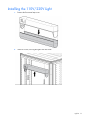
Important safety information
Before installing this product, read the Important Safety Information guide provided.
WARNING: To reduce the risk of personal injury, fire, or damage to the equipment, do not
exceed the recommended voltage for the rack.
WARNING: The fluorescent lamp contains mercury. Therefore, at end-of-life, the fluorescent
lamp may require special handling.
WARNING: To reduce the risk of personal injury or damage to the equipment, be sure that:
•
•
•
•
•
The leveling feet are extended to the floor.
The full weight of the rack rests on the leveling feet.
The stabilizing feet are attached to the rack if it is a single-rack installation.
The racks are coupled together in multiple-rack installations.
Only one component is extended at a time. A rack may become unstable if more than one
component is extended for any reason.
Light kit 76
Installing the 110V/220V Light
1.
Remove the fluorescent lamp cover.
2.
Insert two screws, securing the light to the rack frame.
Light kit 77
3.
Insert the fluorescent lamp pins into the light socket (1) and gently turn the fluorescent lamp toward the
rack (2) until the lamp locks into place.
4.
Replace the fluorescent lamp cover.
Light kit 78
Operating the 110V/220V Light
Item
Description
Status
1
On
Turns on the light.
2
Off
Turns off the light.
3
Standby mode
Turns on the light when the rack door is
open, and turns off the light when the rack
door is closed.
Connecting the power cord to the 110V/220V light
Connecting devices to the 110V/220V light
Light kit 79
WARNING: To reduce the risk of personal injury, fire, or damage to the equipment, do not
exceed the recommended voltage for the rack.
HP 110V/220V light kit specifications
Parameter
Value
Height
116 mm
Depth
50 mm
Width
452 mm
Weight
approximately 1 kg
Rated input
100–240 V, 50/60 Hz
Maximum rated output
10 A/250 VAC
Illuminant
F14W/133-T8, Coolwhite
Protection class
1
Degree of protection
IP20 (IEC 529/EN 60 529)
Power consumption
approximately 27 VA
Current consumption
0, 08 A at 240 V
0, 012 A at 230 V
0, 175 A at 100 V
Operating temperature
-25°C to 50°C
Type of start
Warm start
Candle power
700 lm
Illumination
approximately 90 1X (measured by 1
m distance)
Test standard
UL153, (Portable Lamps), File
E243499 ENEC/GS according
EN60598-1 (at test)
EMC
EN61547, EN55015, EN61000-6-3,
EN61000-6-2, EN61000-3-3
Light kit 80
F14W/133-T8 fluorescent lamp specifications
Electrical data*
Nominal value
Minimum
Maximum
Frequency
50 Hz
—
—
Lamp nominal wattage
14 W
—
—
14.0 W
30 W
12.8 W
—
15.2 W
—
38 V
28V
48 V
395 mA
330 mA
—
—
—
—
590 mA
660 mA
360 mA
—
—
—
Lamp rated wattage
•
•
Single operation
Series operation
Lamp operating voltage
Lamp current
•
•
Single operation
Series operation
Preheat current
•
•
Single operation
Series operation
*Lamps must comply with the requirements of IEC/EN 60081 and IEC/EN 61195, respectively.
Lamp life*
Nominal Value Minimum
Average life (50% failure
rate)
14000 h
Individual life
6000 h
*Life test according to IEC/EN 60081, Annex C.
Operating conditions*
Value
Cap rim temperature
Nominal value maximum 125°C
Lamp ambient temperature
Nominal value minimum -20°C
Ballast impedance
•
•
Single operation
Series operation
285/127, 525/220, 566/230, 612/240
ΩN
507/220, 540/230, 580/240 ΩN
Starter
•
•
Single operation
Series operation
FS-11, FS-22, COP-22
FS-22, COP-22
Any
Burning position
*Starter and Ballast must comply with IEC/EN 60155 and IEC/EN 60921, respectively.
Photometric data
Color
No
Luminous
Flux*
CRI
Color Temp
ILCOS-Code
3 group
2B group
2A group
3000 K
4300 K
6500 K
FD-14/30/3-E-G13-26/360
FD-14/43/2B-E-G13-26/360
FD-14/65/2A-E-G13-26/360
Nominal
Value
Standard colors
•
•
•
Warm white
Cool white
Daylight
129
133
154
700 lm
700 lm
650 lm
Light kit 81
Color
No
Luminous
Flux*
CRI
Color Temp
ILCOS-Code
1A group
n/a
6500 K
n/a
FD-14/65/1A-E-G13-26/360
Not for general lighting
purposes
Nominal
Value
Special colors
•
•
Activa
Gro-lux
172
gro
600 lm
n/a
*At 50-Hz operation, lamp aged for 100 h.
Material disposal
This HP product contains the following material that might require special handling at end-of-life:
•
Mercury in the user replaceable fluorescent lamp.
Disposal of mercury might be regulated because of environmental considerations. For disposal or recycling
information, contact your local authorities or the Electronic Industries Alliance (EIA) (http://www.eiae.org).
Light kit 82
Mini Stabilizer kit
About this device
The HP Mini Stabilizer kit provides stability and support and prevents possible tipping when you install,
remove, or access equipment within the rack.
Kit contents
Item
Quantity
600-mm (23.62-in) Front stabilizer
mount
—or—
800-mm (31.50-in) Front stabilizer
mount
1
Stabilizer feet
2
M8 x 20-mm bolt
8
M8 flat washer
8
1
This kit might contain extra hardware for your convenience.
Required tools
The following tools are required for installation:
•
Ratchet with sockets
•
Adjustable wrench
Installing the stabilizer
NOTE: HP recommends using the side feet, provided with this kit, to stabilize stand-alone racks
from the side. If you are stabilizing racks that are secured together with baying kits, the side feet
are optional on either end of the row.
1.
Align the front foot with the front caster plate.
Mini Stabilizer kit
83
2.
Insert and partially tighten four bolts with washers, securing the front foot to the front caster plate.
3.
If you are using the side feet, align the side feet with the holes on the caster plate skirt and front foot.
Mini Stabilizer kit
84
4.
Insert and partially tighten two bolts with washers, securing the side feet (if installed) and front foot to the
caster plate skirt.
5.
Tighten the bolts from step 2.
6.
Tighten the bolts from step 4.
Installation is complete.
Mini Stabilizer kit
85
Rack Air Duct kit
About this kit
The HP 10000 G2 Rack Air Duct kit removes warm air from the rack by channeling the warm air into the data
center ceiling return air plenum. The air duct sits on top of the rack, directly joined to the ceiling plenum,
preventing the warm air from entering the data center aisle.
Three kits support this product.
Part number Option kit name
Description
AF028A
HP 10642G2 Top Exhaust Extension
Kit
This kit includes the rear extension assembly and rack
air duct assembly.
AF029A
HP 10642G2 Top Exhaust Field Retrofit This kit includes a solid top and bottom rack plate, solid
Kit
rear rack doors, and an airflow gasket, enabling you
to convert your existing HP rack to accommodate the
rack air duct assembly.
AF030A
HP 10642G2 Top Exhaust Rack
This factory custom-to-order rack arrives with a solid
top and bottom rack plate preinstalled on the rack.
If you are converting your current HP rack to accommodate the HP 10000 G2 Rack Air Duct, you must install
the AF029A kit prior to installing the AF028A kit.
If you ordered the AF030A rack, you must install the AF028A kit to the AF030A rack.
Kit contents
The following items are included in your rack option kit:
AF028A HP 10642G2 Top Exhaust Extension Kit
•
•
Extension assembly
o
Extension left side (1)
o
Extension right side (1)
o
Extension top (1)
o
Extension base (1)
o
M5.5 self-tapping screw (6)
o
M6 machine screw (8)
Air duct assembly
o
Upper air duct assembly (1)
— M6 cap screw (4)
— M6 star washer (4)
— M6 flat washer (4)
— M6 nut (4)
Rack Air Duct kit
86
— Draw latch assembly (1)
— Plastic push fastener (4)
— 510-mm foam gasket (2)
— 520-mm foam gasket (2)
o
Lower air duct assembly (1)
— M5.5 self-tapping screw (4)
•
o
M3.5 self-drilling screw (2)
o
M10 x 25 bolt (2)
Baying gaskets
o
876-mm foam gasket (2)
o
1850-mm foam gasket (2)
AF029A HP 10642G2 Top Exhaust Field Retrofit Kit
•
Top rack plate
•
Base rack plate
o
Base plate (2)
o
Egress slot plate (2)
o
M5.5 self-tapping screw (4)
o
6-mm plastic push fastener (2)
o
10-mm plastic tree fastener (2)
•
Solid rear rack doors (2)
•
Airflow rail foam gasket (2)
•
600-mm plastic floor gasket (1)
AF030A HP 10642G2 Top Exhaust Rack
Factory custom-to-order HP 10642G2 rack with a solid top rack plate and a solid bottom rack plate
Required tools
The following tools are required for installation:
•
T-25 Torx driver
•
T-30 Torx driver
•
Adjustable wrench or 17-mm wrench
•
Scissors
•
Electric drill
•
2.38-mm (3/32-in) drill bit
Rack Air Duct kit
87
Installation video
HP recommends watching the HP 10000 G2 Rack Air Duct Installation video. The video provides a
demonstration of installation strategies and techniques that might be helpful while installing the air duct.
To access the video:
1.
Go to the HP website (http://www.hp.com/go/sml).
2.
In the Product category section, select Options and Accessories.
3.
In the Product family section, select Server Rack and Rack Options.
4.
In the Product series section, select HP 10000 G2 Rack Air Duct Kit.
5.
In the Media selection and resources section, select either the Air duct installation video or the Retrofit
kit installation video.
Installing the Top Exhaust Retrofit kit
Follow these instructions to convert your existing HP rack to accommodate the kit.
1.
Remove the perforated rear doors of your rack.
2.
Remove the perforated rack top plate and install the solid rack top plate ("Installing the solid rack top
plate" on page 89).
3.
If necessary, remove any installed components from the bottom two U spaces.
4.
Install the solid rack base plate ("Installing the solid rack base plate" on page 90).
5.
If necessary, replace the installed components in their original rack locations.
6.
Install the airflow gasket to the inside of your rack ("Installing the airflow gasket" on page 91).
7.
Install the floor gasket to your rack ("Installing the floor gasket" on page 93).
Removing the rear doors
1.
Open the hinge brackets by pulling up the top hinge pin and pulling down the bottom hinge pin (1).
2.
Lift the rear doors off the hinge brackets, and then remove the doors from the rack (2).
Rack Air Duct kit
88
3.
Using a T-30 Torx screwdriver, remove the M6 flathead screw securing each hinge bracket to the rack
(1), and then remove all of the hinge brackets from the rack (2). Retain the hinge brackets and screws
for reinstallation.
4.
Using a T-25 Torx driver, remove the upper and lower rear door lock catches by removing the two
screws from each of the upper and lower rear door lock catches. Retain the door lock catches and
screws for reinstallation.
NOTE: Install the solid rear rack doors after you have installed the AF028A kit.
Installing the solid rack top plate
1.
Using a T-30 Torx screwdriver, remove the four M-12 bolts at each corner of the perforated top plate of
the rack (1). Retain the bolts for future use.
Rack Air Duct kit
89
2.
Remove the perforated top plate of the rack (2).
3.
Align the solid plate with the top of the rack (1).
4.
Using a T-30 Torx screwdriver, insert and tighten two of the four M-12 bolts (from step 1) into the two
corner holes at the front of rack (2).
Installing the solid rack base plate
1.
From the rear of the rack, insert the left side plate into the rack, and set the plate on the lip of the rack
frame (1).
NOTE: When you insert the sheet metal screws to secure the base plates, you can either use the
top hole or the side hole, depending on your space allotment.
2.
Using a T-25 Torx screwdriver, insert and tighten one M5.5 self-tapping screw at the rear, left corner
and one M5.5 self-tapping screw at the front, left corner to secure the left side plate to the rack frame
(2).
Rack Air Duct kit
90
3.
Insert the right side plate into the rack, overlapping the left side plate, and set it on the lip of the rack
frame (3).
4.
Using a T-25 Torx screwdriver, insert and tighten one M5.5 self-tapping screw at the rear, right corner
and one M5.5 self-tapping screw at the front, right corner to secure the right side plate to the rack frame
(4).
5.
From the rear of the rack, align the two egress cover plates with the egress slot at the rear of the rack (1).
6.
Secure the egress cover slot.
a. Insert two 10-mm plastic tree fasteners into the two rear holes, through the caster plate (2).
b. Insert two 6-mm plastic push fasteners into the two front holes, through the base plate (3).
Installing the airflow gasket
1.
Using scissors, cut the airflow rail gasket to fit the size of your rack.
2.
Insert the airflow rail gasket into the rack front door on both sides of the rack.
Rack Air Duct kit
91
3.
Insert the airflow rail gasket into the space between the 19-in mounting rails and the vertical frame on
both sides of the rack, with the closed cell side of the airflow rail gasket facing the front of the rack.
4.
Gently push the airflow rail gasket into the space until it is flush with the vertical frame.
For more information, see the HP Airflow Optimization Kit Installation Instructions (AF090A).
Rack Air Duct kit
92
Installing the floor gasket
1.
Cut the floor gasket at the perforation to reduce the length from 800-mm (31-in) to 600-mm (24-in).
2.
Remove the protective tape from the bottom edge of the floor gasket, and then apply it to the bottom of
the rack with the adhesive strip facing the front of the rack.
Installation is complete.
Installing the Top Exhaust Extension kit
Follow these instructions to install the AF028A Top Exhaust Extension Kit, either to an AF030A Top Exhaust
Rack or after you have installed the AF029A kit to an existing HP retrofit rack.
1.
Remove the rear doors and door hinges from the rear of your rack.
2.
Install the rear extension assembly to your rack.
3.
Install the solid rear doors to the extension assembly.
Rack Air Duct kit
93
4.
Assemble the kits ("Assembling the kits" on page 98).
5.
Install the kit assembly to the top of your rack.
6.
Adjust the height of the kit.
Removing the rear doors
1.
Open the hinge brackets by pulling up the top hinge pin and pulling down the bottom hinge pin (1).
2.
Lift the rear doors off the hinge brackets, and then remove the doors from the rack (2).
3.
Using a T-30 Torx screwdriver, remove the M6 flathead screw securing each hinge bracket to the rack
(1), and then remove all of the hinge brackets from the rack (2). Retain the hinge brackets and screws
for reinstallation.
Rack Air Duct kit
94
4.
Using a T-25 Torx driver, remove the upper and lower rear door lock catches by removing the two
screws from each of the upper and lower rear door lock catches. Retain the door lock catches and
screws for reinstallation.
NOTE: Install the solid rear rack doors after you have installed the AF028A kit.
Installing the rear extension assembly
1.
Install the side assemblies of the rear extension assembly.
a. Align the right-side assembly with the rack frame (1).
b. Hook the extension into the rack frame at the three hook locations at the top, middle, and bottom of
the rack.
c.
Using a T-25 Torx screwdriver, insert and tighten one M5.5 self-tapping screws into each of the
three hook locations to secure the side assembly to the rack frame (2).
Rack Air Duct kit
95
d. Repeat steps a through c for the left-side assembly.
2.
Install the top assembly of the rear extension assembly.
a. Align the top assembly with the installed side assemblies (1).
b. Using a T-25 Torx driver, insert and tighten two M6 machine screws into the rear screw holes (2).
c.
3.
Using a T-25 Torx driver, insert and tighten two M6 machine screws into the front screw holes (3).
Install the bottom assembly of the rear extension assembly.
a. Align the bottom assembly with the installed side assemblies (1), making sure to set the metal tab at
the front of the assembly over the rear rack frame (2).
Rack Air Duct kit
96
b. Using a T-25 Torx driver, insert and tighten four M6 machine screws into each corner hole (3).
Installing the solid rear doors
1.
Using a T-25 Torx driver, insert and tighten two screws into each of the upper and lower rear door lock
catches.
2.
Install the hinges brackets.
a. Align the eight hinge brackets that you removed from the rear of your rack to the designated
locations on the rear extension assembly (1).
Rack Air Duct kit
97
b. Using a T-30 Torx driver, insert and tighten one M6 flathead screw to secure each hinge bracket to
the rear extension assembly (2).
3.
Lift the rear doors, aligning them with the hinge brackets on the rear extension assembly (1).
4.
Push down the hinge pins, and then insert the hinge into the holes on the rear door (2).
Assembling the kits
1.
Assemble the lower duct.
a. Align the hooks of the side panels with the slots of the front and back panels (1).
b. Slide the six hooks into the slots, and then slide the panel down until it locks in place (2).
Rack Air Duct kit
98
c.
Insert one M5.5 self-tapping screw into each bottom corner of the assembly (3).
d. Repeat steps a through c for the other side panel.
2.
Assemble the upper duct.
a. Align the hooks of the side panels with the slots of the front and back panels (1).
b. Slide the six hooks into the slots, and then slide the panel down until it locks in place (2).
c.
From the inside of the assembly, insert two M6 cap screws in the middle of the assembly. Using an
adjustable wrench, secure the screws from outside the assembly with an M6 star washer, an M6 flat
washer, and a nut (3).
d. Repeat steps a through c for the other side panel.
3.
Install the draw-latch straps to the upper duct assembly.
a. Slide the draw-latch strap around the bottom of the upper duct assembly (1).
b. Align the holes of the draw-latch strap with the holes of the upper duct assembly.
Rack Air Duct kit
99
c.
Insert two plastic push fasteners into the holes on both sides of the assembly to secure the draw-latch
strap to the upper duct assembly (2).
d. Repeat steps a through c for the second draw-latch strap.
4.
With the draw-latch straps in the loose position, slide the upper duct down over the lower duct.
5.
Lock the draw-latch straps.
NOTE: The two 510-mm gaskets sit on the inside edges of the two 520-mm gaskets.
Rack Air Duct kit
100
6.
Apply the foam gasketing to the top of the upper duct by peeling the adhesive backing and aligning the
gasketing with the top edges of the upper duct.
Installing the kit assembly
WARNING: The rack air duct weighs approximately 22.5 kg (50 lb). To reduce the risk of
personal injury or damage to the equipment:
• Observe local occupational health and safety requirements and guidelines for manual
material handling.
• Use at least two people to lift and stabilize the product during installation or removal.
• Use step stools to install the product to the top of the rack. Do not lift the air duct over your
head.
1.
Using a T-30 Torx screwdriver, remove the two rear M-12 bolts from the top plate of the rack. Retain the
bolts for future use.
2.
Align the open slots of the lower air duct to the mounting holes on the top of the rack.
3.
Slide the air duct toward the front of the rack, until the front edge slides under the metal slots on the top
plate of the rack (1).
NOTE: You might need to slightly raise the upper duct to access the bolts.
4.
Using an adjustable wrench, insert and tighten two M-10 bolts through the holes of the air duct
assembly and into the cage nut holes on top the side assemblies (2).
Rack Air Duct kit
101
5.
Using a T-30 Torx screwdriver, insert and tighten two M-12 bolts (from step 1) through the holes of the
air duct assembly and into the two rear holes of the rack (3).
Adjusting the kit
After you have installed the air duct to the top of your rack:
1.
Loosen both draw-latch straps (1).
2.
Raise the upper duct until it reaches the ceiling opening, and the gasketing is pressed firmly against the
ceiling (2).
3.
Tighten and lock both draw-latch straps to hold the upper duct in place (1).
4.
To lock the air duct in the raised position:
a. Mark through the pre-drilled hole on the upper duct, so you know where the hole should be on the
lower duct.
Rack Air Duct kit
102
b. Using an electric drill, drill one 2.38-mm (3/32-in) hole through the lower duct, in the location you
marked.
c.
Insert one M3.5 self-drilling screw through the holes in both the upper and lower ducts (2).
Baying options
You can order the HP Baying Rack Option Kit to bay your HP 10000 G2 Rack Air Duct rack to another HP
10000 G2 Rack Air Duct rack. You cannot bay an HP 10000 G2 Rack Air Duct rack to a standard rack.
You must install the included gaskets to your HP 10000 G2 Rack Air Duct rack prior to baying, to ensure that
the air continues to be channeled up the air duct and not out the sides of the bayed rack.
To install the gasket strips to your rack:
1.
Remove the liner backing from each of the four gasket strips.
2.
Attach the two 876-mm gasket strips to the top and bottom frames of the side of the rack.
3.
Attach the two 1875-mm gasket strips to the front and rear frames of the side of the rack.
Rack Air Duct kit
103
For more information, see Baying kit (on page 25).
Rack Air Duct kit
104
Rear Extension kit
About this device
The HP Rear Extension kit enables you to add 200-mm (7.87-in) of depth to the rear of the HP 10000 Series
and HP 10000 G2 Series racks.
The HP Rear Extension kit only fits the 600-mm (23.62-inch) wide (42U and 47U) rack models.
Kit contents
Item
Quantity
Rear extension assembly
1
•
•
•
•
Left side assembly
Right side assembly
Top assembly
Bottom assembly
M5.5 self tapping screw
8
M6 machine screw
8
Rear extension cord
3
Cable management bracket
6
This kit might contain extra hardware for your convenience.
Required tools
The following tools are required for installation:
•
T-25 Torx driver
•
T-30 Torx driver
Removing the rear doors
1.
Open the hinge brackets by pulling up the top hinge pin and pulling down the bottom hinge pin (1).
Rear Extension kit 105
2.
Lift the rear doors off the hinge brackets, and then remove the doors from the rack (2).
3.
Using a T-30 Torx screwdriver, remove the M6 flathead screw securing each hinge bracket to the rack
(1), and then remove all of the hinge brackets from the rack (2). Retain the hinge brackets and screws
for reinstallation.
Rear Extension kit 106
4.
Using a T-25 Torx driver, remove the upper and lower rear door lock catches by removing the two
screws from each of the upper and lower rear door lock catches. Retain the door lock catches and
screws for reinstallation.
Installing the rear extension assembly
1.
Install the side assemblies of the rear extension assembly.
a. Align the right-side assembly with the rack frame (1).
b. Hook the extension into the rack frame at the three hook locations at the top, middle, and bottom of
the rack.
c.
Using a T-25 Torx screwdriver, insert and tighten one M5.5 self-tapping screws into each of the
three hook locations to secure the side assembly to the rack frame (2).
d. Repeat steps a through c for the left-side assembly.
2.
Install the top assembly of the rear extension assembly.
Rear Extension kit 107
a. Align the top assembly with the installed side assemblies (1).
b. Using a T-25 Torx driver, insert and tighten two M6 machine screws into the rear screw holes (2).
c.
3.
Using a T-25 Torx driver, insert and tighten two M6 machine screws into the front screw holes (3).
Install the bottom assembly of the rear extension assembly.
a. Align the bottom assembly with the installed side assemblies (1), making sure to set the metal tab at
the front of the assembly over the rear rack frame (2).
b. Using a T-25 Torx driver, insert and tighten four M6 machine screws into each corner hole (3).
Rear Extension kit 108
4.
Insert the filler panels into the side and top assemblies.
Installing the rear doors
1.
Using a T-25 Torx driver, insert and tighten two screws into each of the upper and lower rear door lock
catches.
2.
Install the hinges brackets.
a. Align the hinge brackets that you removed from the rear of your rack to the designated locations on
the rear extension assembly (1).
Rear Extension kit 109
b. Using a T-30 Torx driver, insert and tighten one M6 flathead screw to secure each hinge bracket to
the rear extension assembly (2).
3.
Lift the rear doors, aligning them with the hinge brackets on the rear extension assembly (1).
4.
Push down the hinge pins, and then insert the hinge into the holes on the rear door (2).
Installing the cable management brackets
1.
Position the cable management bracket so that one side is attached to the inside of the rack frame while
the other side is attached to the inside of the extension kit.
2.
Slide the cable management bracket into place (1).
Rear Extension kit 110
3.
Using a T-25 Torx driver, insert and tighten one M5.5 self-tapping screw into each side of the bracket
to secure the cable management bracket to the rack frame and extension kit (2).
Installation is complete.
Rear Extension kit
111
Server/Utility Shelf kit
About this device
The HP Server/Utility Shelf kit enables you to install a convenient shelf in your rack-mount system. This kit can
be used with all HP racks.
Kit contents
Item
Quantity
Server/Utility shelf
1
Cage nut
2
M6 screw
2
Quick-release tie-down straps
2
This kit might contain extra hardware for your convenience.
Required tools
The following tools are required for installation:
•
Phillips screwdriver
•
Cage nut insertion tool
Installing the server/utility shelf
Always plan the rack installation so that the heaviest item is on the bottom of the rack. Install the heaviest item
first, and then continue to populate the rack from the bottom to the top.
Server/Utility Shelf kit
112
1.
Align the cage nuts with the square-rail perforations on the front of the shelf.
2.
Use the cage nut insertion tool (not included) to secure each cage nut to the shelf.
a. Hook the bottom lip of the cage nut in the square-rail perforation.
b. Insert the tip of the insertion tool through the perforation, and then hook the top lip of the cage nut.
c.
Pull the cage nut through the square-rail perforation until the top lip snaps into position.
3.
Firmly hold the shelf, and then insert the shelf into the rack, tilting the shelf slightly so that the rear teeth
on the shelf clear the rear of the rack.
4.
Straighten the shelf, and then insert the rear teeth into the mounting holes on the rear of the rack.
Server/Utility Shelf kit
113
5.
Align each cage nut assembly with the mounting holes on the inside front of the rack.
6.
Secure the shelf to the rack with two M6 screws using a Phillips screwdriver.
Server/Utility Shelf kit
114
7.
Secure servers to the shelf using the quick-release tie-down straps.
Installation is complete.
Server/Utility Shelf kit
115
Side Panel kit
About this device
The HP Side Panel kit enables you to attach side panels to HP 10000 G2 Series Racks.
Kit contents
Item
Quantity
Top side panel
2
Middle side panel
2
Bottom side panel
2
Key
2
This kit might contain extra hardware for your convenience.
Required tools
No tools are required for this procedure.
Side Panel kit
116
Installing the side panels
1.
Install the top and bottom side panel by sliding the brackets on the side panel behind the tabs on the
rack frame.
Side Panel kit
117
2.
Install the middle side panel by locking the side panel locks, securing it to the rack.
3.
Repeat steps 1 and 2 for the other side of the rack.
Installation is complete.
Side Panel kit
118
Tie-Down kit
About this device
The HP 10000 G2 Series Rack Tie-down Kit enables you to secure HP 10000 G2 Series Racks to the floor.
This kit is for all 10000 G2 Series Racks except for Rack SKUs AF092A and AF094A.
A separate tie-down kit is used exclusively for the 1200 full frame racks. This separate kit is for Rack SKUs
AF092A and AF094A only.
Required tools
The following tools are required for installation:
•
Ratchet with sockets
•
Adjustable wrench
Kit contents
Item
Quantity
Front tie-down bracket
1
Rear tie-down bracket
1
M8 x 20-mm bolt
8
M8 flat washer
8
M8 spring clip
4
This kit might contain extra hardware for your convenience.
Installing the tie-down kit
This procedure is for all 10000 G2 Series racks except for Rack SKUs AF092A and AF094A.
To install the tie-down kit:
1.
Adjust the leveling feet on the rack so that the full weight of the rack rests on the leveling feet.
2.
Align the front tie-down with the holes on the front caster plate.
Tie-Down kit 119
3.
Insert and partially tighten four bolts with washers, securing the front tie-down to the front caster plate.
4.
Align the rear tie-down with the holes on the rear caster plate (1).
5.
Insert the four spring clips (2), and then partially tighten four bolts with washers (3), securing the rear
tie-down to the rear caster plate.
6.
Tighten the bolts from step 3.
7.
Tighten the bolts from step 5.
8.
Secure the rack to the floor ("Securing the rack to the floor" on page 121).
Installation is complete.
Tie-Down kit 120
Securing the rack to the floor
The following illustration indicates where to drill the holes to secure the rack to the floor. The distances are
measured from the holes on the tie-downs. Have your building structural engineer drill the holes. After your
holes have been drilled, insert a bolt with a washer into each hole to secure the rack to the floor.
1200 mm Full Frame Rack Tie-down Kit
The HP 10000 G2 Series Rack 1200mm Full Frame Pack tie-down kit is designed for greater stability in
seismic environments. This tie-down kit is for Rack SKUs AF092A and AF094A only.
Required tools
The following tools are required for installation:
•
Ratchet with sockets
•
Adjustable wrench
1200 mm full frame rack tie-down kit contents
Item
Quantity
Front tie-down bracket
1
Rear tie-down bracket
1
M8 x 20-mm bolt
12
M8 x 20-mm bolt
12
M8 flat washer
12
This kit might contain extra hardware for your convenience.
Installing the 1200 mm full frame rack tie-down kit
This procedure is only for rack SKUs AF092A and AF094A.
To install the kit:
Tie-Down kit 121
1.
Adjust the leveling feet on the rack so that the full weight of the rack rests on the leveling feet.
2.
Align the front tie-down with the holes on the front caster plate.
3.
Insert and then partially tighten four bolts with washers, securing the front tie-down to the front caster
plate.
4.
Align the rear tie-down with the holes on the rear caster plate (1).
5.
Insert the six bolts with washers (2), securing the rear tie-down to the rear caster plate.
6.
Tighten the bolts from step 3.
7.
Tighten the bolts from step 5.
8.
Secure the rack to the floor ("Securing the 1200 mm full frame rack to the floor" on page 123).
Installation is complete.
Tie-Down kit 122
Securing the 1200 mm full frame rack to the floor
The following illustration indicates where to drill the holes to secure the 1200 mm full frame rack to the floor.
The distances are measured from the holes on the tie-downs. Have your building structural engineer drill the
holes. Then secure the rack to the floor by inserting a bolt with a washer into each hole.
Tie-Down kit 123
Vertical PDU Mounting kit
About this device
The HP Vertical PDU Mounting kit allows HP PDU vertical models to be mounted in HP 10000 G2 Series
Racks and in the HP V142 Rack.
Kit contents
Item
Quantity
Top bracket
1
Bottom bracket
1
Phillips self tapping screw
4
8-32 Torx machine screw
2
Required tools
The following tools are required for installation:
•
Phillips screwdriver
•
8-32 screwdriver
Installing the Vertical PDU Mounting kit
1.
Install the brackets.
HP basic PDU
Vertical PDU Mounting kit 124
HP monitored PDU
2.
Install the PDU.
The installation is complete.
Vertical PDU Mounting kit 125
Electrostatic discharge
Preventing electrostatic discharge
To prevent damaging the system, be aware of the precautions you need to follow when setting up the system
or handling parts. A discharge of static electricity from a finger or other conductor may damage system
boards or other static-sensitive devices. This type of damage may reduce the life expectancy of the device.
To prevent electrostatic damage:
•
Avoid hand contact by transporting and storing products in static-safe containers.
•
Keep electrostatic-sensitive parts in their containers until they arrive at static-free workstations.
•
Place parts on a grounded surface before removing them from their containers.
•
Avoid touching pins, leads, or circuitry.
•
Always be properly grounded when touching a static-sensitive component or assembly.
Grounding methods to prevent electrostatic discharge
Several methods are used for grounding. Use one or more of the following methods when handling or
installing electrostatic-sensitive parts:
•
Use a wrist strap connected by a ground cord to a grounded workstation or computer chassis. Wrist
straps are flexible straps with a minimum of 1 megohm ±10 percent resistance in the ground cords. To
provide proper ground, wear the strap snug against the skin.
•
Use heel straps, toe straps, or boot straps at standing workstations. Wear the straps on both feet when
standing on conductive floors or dissipating floor mats.
•
Use conductive field service tools.
•
Use a portable field service kit with a folding static-dissipating work mat.
If you do not have any of the suggested equipment for proper grounding, have an authorized reseller install
the part.
For more information on static electricity or assistance with product installation, contact an authorized
reseller.
Electrostatic discharge
126
Support and other resources
Before you contact HP
Be sure to have the following information available before you call HP:
•
Active Health System log (HP ProLiant Gen8 or later products)
Download and have available an Active Health System log for 3 days before the failure was detected.
For more information, see the HP iLO 4 User Guide or HP Intelligent Provisioning User Guide on the HP
website (http://www.hp.com/go/ilo/docs).
•
Onboard Administrator SHOW ALL report (for HP BladeSystem products only)
For more information on obtaining the Onboard Administrator SHOW ALL report, see the HP website
(http://www.hp.com/go/OAlog).
•
Technical support registration number (if applicable)
•
Product serial number
•
Product model name and number
•
Product identification number
•
Applicable error messages
•
Add-on boards or hardware
•
Third-party hardware or software
•
Operating system type and revision level
HP contact information
For United States and worldwide contact information, see the Contact HP website
(http://www.hp.com/go/assistance).
In the United States:
•
To contact HP by phone, call 1-800-334-5144. For continuous quality improvement, calls may be
recorded or monitored.
•
If you have purchased a Care Pack (service upgrade), see the Support & Drivers website
(http://www8.hp.com/us/en/support-drivers.html). If the problem cannot be resolved at the website,
call 1-800-633-3600. For more information about Care Packs, see the HP website
(http://pro-aq-sama.houston.hp.com/services/cache/10950-0-0-225-121.html).
Support and other resources
127
Acronyms and abbreviations
KVM
keyboard, video, and mouse
PDU
power distribution unit
RKM
rackmount keyboard monitor
TMRA
recommended ambient operating temperature
UPS
uninterruptible power system
Acronyms and abbreviations 128
Documentation feedback
HP is committed to providing documentation that meets your needs. To help us improve the documentation,
send any errors, suggestions, or comments to Documentation Feedback (mailto:[email protected]).
Include the document title and part number, version number, or the URL when submitting your feedback.
Documentation feedback
129