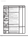
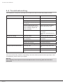
1
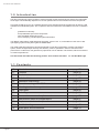
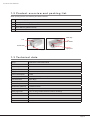
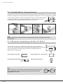
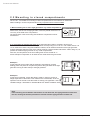
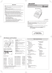
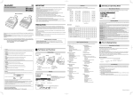
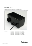
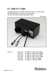
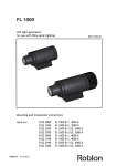
FL 150-3 B
Metal Halide Light Generator
for Fiber Optic Lighting Systems
This user manual describes the following product:
Item number 0161 0000
FL 150-3 B. White light.
99082019 Rev. 30.06.09
User Manual
FL150-3 User Manual
1.0 Introduction
The fiber optic lighting system consists of a light generator as the electrical device and the fiber harnesses
as the light. The functionality depends on how it is operated and on the maintenance of the components.
This guide should serve you as a guideline and the forms and lists should be a helpful tool to assure a well
operated and maintained system. The compliance with the maintenance formalities is the main contribution
to
·
·
·
·
guarantee functionality
an expanded life span of the components
save avoidable replacement costs
have a satisfying, uninterrupted system illumination
Your Roblon Fiber Optics metal halide light generator, type FL 150 - 3, is intended for indoor use in fiber
optic lighting systems using either glass or PMMA fibers.
The metal halide light generator has been developed to meet the requirements of a fiber optic lighting
system, where the light output intensity and efficiency must be optimized in order to ensure the best
performance. Furthermore, this generator is prepared for use in cabinets or showcases, either semi-closed
or closed compartments.
This document describes the following product: Item number 0161 0000
FL 150-3B. White light.
1.1 Contents
Page 02
1.0
Introduction
page 02
1.1
Contents
page 02
1.2
Product overview
page 03
1.3
Technical data
page 03
2.0
Installation instructions
page 04
2.1
General mounting of FL 150-3
page 04
2.2
Mounting in closed compartments
page 05
3.0
Fiber types
page 06
4.0
Switching on
page 06
5.0
Care, maintenance and replacement
page 07
5.1
Maintenance tasks and explanations
page 07
5.2
Replacement tasks and explanations
page 09
6.0
Troubleshooting
page 10
7.0
Spare parts and accessories
page 11
FL150-3 User Manual
1.2 Product overview and packing list
When opening the box, the following should be included:
1
FL 150-3 B light generator
1
Lamp (fitted in the light generator)
1
Power cord
1
3mm Allen key (fitted in the lid)
1
User manual
Allen key
Lid
Air intake
Air exhaust
Supply fuse
Light port
1 . 3 Te c h n i c a l d a t a
Lamp:
CDM-SA/R 150W Metal halide
CRI:
96
Colour temp:
4200K
Light port:
Ø28
Supply:
100 - 240V (Nominal) 50 or 60 Hz
Power consumption:
178W
Cooling system:
12VDC axial fan (80x80mm)
Fan Noise level:
28,5 dB(A)
Thermal protection:
Auto reset
Ambient temperature:
-30°C to 40°C
Dimensions (WxDxH):
170x257x110mm
Weight:
1,9kg
Safety approvals:
cUL, UL153 (portable cabinet luminaire, E233873)
CB, IEC 60598
FCc, Part 15
EMC, EN 50015, EN 61000, EN 61547
PSE, CE
Page 03
FL150-3 User Manual
2.0 Installation instructions
Unpack the unit, and make sure that the grounded power supply cord is suitable for your country. The light
generator is prepared for universal power input, capable of running from 100 - 240 V (nominal) 50 or 60 Hz.
1. Insert the fiber harness’ common end fully into the output port of the light generator.
2. Tighten the grille screw with the supplied Allen key, which is stored in the lid.
3. Connect the power supply lead into the back of the light source.
Note.
Before switching on, make sure that the requirements from the installation instructions
are observed.
2.1 General mounting of the FL150-3
Are available for mounting two unidirectional keyholes (1) with a distance of
125 mm. The keyholes are suitable for screws with a head diameter of max. Ø9 mm.
One of the keyholes is accessible from the inside of the light generator for
fastening the mounting screw.
125 mm
1
Free-standing on a shelf: Ceiling suspension - upside down:
Horizontally wall mounted: Vertically wall mounted:
Note.
When installing in any direction, please make sure that the hot air from
one light generator does not blow directly into the air intake of the
light generator next to it.
Page 04
FL150-3 User Manual
2.2 Mounting in closed compartments
The FL 150 - 3 is suitable for mounting in closed compartments such as cabinets or showcases.
When installing in closed compartments two very important criteria must be fulfilled.
1. When installing one or more light generators in a closed compartment
the volume of the chamber cannot be less than 0,35m3 per light generator.
Furthermore, the back of the light generator cannot be placed closer than 15
cm to any of the walls of the compartment
The temperature of the surrounding area inside the compartment cannot
exceed 40°C.
Volume: Min. 0.35 m3
Min.
15 cm
Temperature: Max. 40oC
Volume: Min. 0.35 m3
2. In compartments smaller than 0,35 m³ the light generator needs to »breathe« to
keep cool.
Min.
Volume: Min. 0.35 m3
15 air
cm
Ventilation holes must be made in the compartment corresponding to min. 50 cm² of
intake and min. 50
Min.
cm² of exhaust air. When using this installation method, the air intake and exhaust of
the
light generator
15 cm
must be separated. Also the holes of the cabinet must be pointed in different directions.
When
doing
Temperature: Max.
40oCso, it is
possible to install the light generator in very small compartments.
Temperature: Max. 40oC
Also here, the temperature of the surrounding area cannot exceed 40 °C.
Some examples of seperation of air intake and air outlet holes are given below.
Example 1.
In this example, the air intake and the exhaust is separated by a space
dividing plate. This plate can be placed anywhere along the sides of the light
generator as long as it fits exactly to the light generator.
1.
Example 2.
In this second example, a hose-like fitting is made. In order to ensure an
airtight separation of the airflow. This method is the most flexible, as the air
separator can be formed to suit the needs of exactly your application. Use e.g.
ventilation flange +7800 0505 for standard Ø100 mm flexible ventilation hose.
Note.
If the mounting and ventilation instructuion are not observed, the light generator will become
too hot, causing the thermal protection to activate and the light generator to switch off.
Page 05
FL150-3 User Manual
3 . 0 Fiber types
All glass and plastic (PMMA) optical fibers can be used with the FL 150 - 3.
Endlight as well as sidelight is applicable.
For all fiber types:
• Do not bend more than the max
allowable bend radius
• Do not pull or jerk the fiber
• Do not step on the fiber
4 . 0 Switching on
When the fiber bundle is secured and the power cord is inserted, the unit may be connected to the main
supply.
Note.
With this type of lamp about 2 - 5 minutes will elapse from switching on until the lamp is
delivering full light output.
CAUTION
To reduce the risk of fire, electric shock, or injury to persons:
!
a) Use only insulated staples or plastic tie to secure cords.
b) Route and secure the cords so that they will not be pinched or damaged when the cabinet is pushed
to the wall.
c) Position the portable cabinet light generator with respect to the cabinet so that the lamp replacement markings can be read during relamping.
d) Not intended for recessed installation in ceilings or soffits.
When using the light generator mounted on a surface, the following must be observed
a) Not intended for surface installation inside built-in furnishings such as kitchen cabinets, china cabinets
or trophy cases.
b) The portable cabinet light generator may be installed under a kitchen cabinet when the power supply
cord is not concealed or run through openings in the cabinet.
c) Do not conceal the power supply cord (or power supply) inside a wall, ceiling, soffit, kitchen cabinet or
similar permanent structure.
d) Do not run the power supply cord through holes in walls, ceilings or floors.
SAVE THESE INSTRUCTIONS
Page 06
FL150-3 User Manual
5.0 Care, maintenance and replacement
Please observe the maintenance schedule very carefully in order to ensure the optimal performance of the
lighting system.
5.1 Maintenance tasks and explanations
Component
Tasks and explanation
Inspection
period
Operator
A. Light generator
environment
vacuuming
Vacuum the surrounding space of the light
generator.
The generator needs a dust-free environment.
therefore please remove the dust by vacuuming
the surrounding space.
Monthly
Retailer
Monthly
Retailer
Once a year
Retailer
Volume: Min. 0.35 m3
Min.
15 cm
B. Light generator
Temperature: Max. 40 C
environment
o
The outer housing of the light generator can be
cleaned with a soft damp cloth when necessary.
Inspect the surrounding space of the light
generator.
The ventilation slits and the ventilator can not
be covered; good air circulation is absolutely
necessary.
Note:
Light generators placed in a cabinet have a
certain space, which is dertemined for the
generator and this space has to be kept free!
Please refer to the installation instructions in
this manual for specific measures.
C. Light generator fan
Inspect the light generator fan and if
necessary change.
The running fan usually gives a slight noise. You
can feel the air blowing by holding the hand next
to the fan.
The fan should be cleaned with a damp cloth
and the cooling grille can also be cleaned with a
damp cloth.
If the fan is not running, unplug the main supply
cord, let the generator cool down and take the
generator out of the cabinet.
If the fan fails to work because it has reached
end of life, it needs to be replaced. Then follow
the instructions in section 5.2.
Note: Do not operate with a defective fan.
Page 07
FL150-3 User Manual
Component
Tasks and explanation
Inspection
period
Operator
D. Light generator
glass filters
Inspect and clean the glass filters and if
necessary change.
The glass filters and the harness common end
of the fiber optics should be wiped with a dry,
lintfree cloth when cold.
Twice a year
and always
when you
change the
lamp
Retailer
Always when
you change the
lamp
Retailer
Change the filters if the glass is broken or
cracked.
Note: do not use alcohol or any other solvent
to clean the fibre harness common end.
Please take the following steps:
1. Take out the lamp
2. Release the filter system that keeps the lamp
in place.
3. Jiggle out the filter system by pulling the
bracket towards the back of the generator and
take it out of the box.
4. Clean the filters (Remove the filters from the
bracket by releasing the spring clip that holds
the filters.The filters´ relative position should
be observed when reinstalling). The thick
filter must always be placed closest to the fiber
end.
5. Install the filters and the lamp by reversing the
above procedure.
The same procedure may be used when
installing an optional dichroic colour filter.
Note: The generator can not be used without
filters! Filters and surrounds can never be
inserted the wrong way.
E. Light generator
fiber connection
Inspect and clean the fibre connection
surface.
Clean the fiber harness common end with a
damp lintfree cloth, but do not touch it with the
fingers.
If the surface looks burnt, has black dots on it
or looks yellow please inform Fiber Optics sales
representative. Further action will then be taken.
Note: Do not bend or pull the cable, as the
harness may be fix connected with the
cabinet.
Page 08
FL150-3 User Manual
5.2 Replacements tasks and explanations
Component
Tasks and explanation
Replace period
Operator
A. Lamp replacement
Before replacing the lamp, please make sure that
the unit is switched OFF. Allow it to cool off.
By lamp defect
or after 6,000
operating hours
Retailer
When defective
Retailer
When defective
Retailer
Please take the following steps:
1. Remove the lid.
2. Disconnect the lamp.
3. Release the lamp plug and lift out the lamp.
4. Install a new lamp, reversing the procedure.
See the instructions on the light generator !!!
B. Fan / ventilator
replacemnet
Changing the fan is easily done. It is only
necessary to release one Allen screw
Please take the following steps:
1. Remove the screw at the back. Use Allen Key.
2. Tip the back plate out, starting from the top.
3. Remove the bracket from the hinge.
5. Release the fan from the bracket.
6. Release the fan plug from the light generator.
7. Install a new fan by reversing 1 to 5.
8. Make sure that the fan runs freely after installing again.
C. Supply fuse
replacement
The supply fuse is placed in the mains supply
socket. The fuse is exchanged by releasing the
fuse drawer from the mains supply socket and
removing the fuse from here. Use Ø 5X20mm
type 5 AT.
Page 09
FL150-3 User Manual
6 . 0 Tr o u b l e s h o o t i n g
If you experience a faulty unit, go through this checklist to be able to resolve the problem yourself.
Symptom
Cause?
Solution
No light
Is the power ON?
Turn on the power.
Is the supply fuse intact?
Replace the fuse.
Is the power cord properly
connected?
Reinsert the power cord.
Is the lid closed and the screw
turned completely tight (interlock
will be activated)? Tighten the
screw completely
Tighten the screw completely.
Close and secure the lid.
Is the light generator too hot?
Check with the installation
instructions.
Cool off for 10 minutes then try
again.
No light, fan running
Is the lamp blown
Replace lamp with new one.
Light switches ON/OFF
Is the light generator too hot
while operating?
Check with installation
instructions.
Is the fan blocked?
Clear the airways.
Is the fan not running?
Reinsert the fan plug.
Is the fan still not running?
Replace the fan with a new one.
Is the lamp old?
Replace the lamp with a new
one.
Are the filters dirty?
Clean the filters.
Is the fiber harness common end
dirty?
Clean the harness common end.
The light output has diminished.
If the unit has been fully checked corresponding to the above listed procedure and the light output is still
not satisfactory, please contact your supplier.
Warning.
Only a properly trained person should undertake the work of servicing other than the above
mentioned.
Page 10
FL150-3 User Manual
7.0 Spare parts and accessories
Description
Type
Roblon item number
Lamp
Philips CDM-SA/R 150W
6515 0005
Fan
Sunon KDE 1208PTB3
6408 0124
CTC filter -900K
Reduces colour temperature from
4200K to 3300K (40x40x1,3mm)
5100 0201
CTC filter -1200K
Reduces colour temperature from
4200K to 3000K (40x40x1,3mm)
5100 0206
CTC filter KW65
Reduces colour temperature
(40x40x1,3mm)
5100 0208
Colour filter yellow
Yellow dichroic colour filter
(40x40x1,3mm)
5400 5002
Colour filter green
Green dichroic colour filter
(40x40x1,3mm)
5400 5003
Colour filter blue
Blue dichroic colour filter
(40x40x1,3mm)
5400 5005
Colour filter red
Red dichroic colour filter
(40x40x1,3mm)
5400 5006
Harness adaptor
Reduces the lightport size from Ø28
to Ø9
7800 0130
Ventilation hose
adaptor
For connecting light generator to
Ø100mm flexible ventilation hose.
7800 0505
Page 11
Roblon accepts no responsibility for possible errors in printed and electronic material. Roblon reserves the right to alter
or discontinue products without notice. © 2012, Roblon A/S.
Roblon Lighting
Nordhavnsvej 1
9900 Frederikshavn
Denmark
Tel: +45 9620 3366
Fax:+45 9620 3396
[email protected]
www.roblon.com