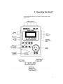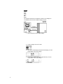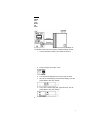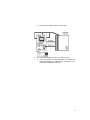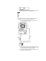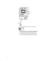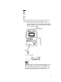
1
QA-ST User and Service Manual QA-ST Safety Tester North American Version 1.1 Copyright 2000 by METRON. All rights reserved. METRON: USA__ 1345 Monroe NW, Suite 255A Grand Rapids, MI 49505 Phone: (+1) 888 863-8766 Fax: (+1) 616 454-3350 E-mail: [email protected] FRANCE ________________ NORWAY________________ 30, rue Paul Claudel Travbaneveien 1 91000 Evry, France N-7044 Trondheim, Norway Phone: (+33) 1 6078 8899 Phone: (+47) 7382 8500 Fax: (+33) 1 6078 6839 Fax: (+47) 7391 7009 E-mail: [email protected] E-mail: [email protected] Disclaimer METRON provides this publication as is without warranty of any kind, either express or implied, including but not limited to the implied warranties of merchantability or fitness for any particular purpose. Further, METRON reserves the right to revise this publication and to make changes from time to time to the content hereof, without obligation to METRON or its local representatives to notify any person of such revision or changes. Some jurisdictions do not allow disclaimers of expressed or implied warranties in certain transactions; therefore, this statement may not apply to you. Limited Warranty METRON warrants that the QA-ST Safety Tester will substantially conform to published specifications and to the documentation, provided that it is used for the purpose for which it was designed. METRON will, for a period of twelve (12) months from date of purchase, replace or repair any defective simulator, if the fault is due to a manufacturing defect. In no event will METRON or its local representatives be liable for direct, indirect, special, incidental, or consequential damages arising out of the use of or inability to use the QA-ST Safety Tester, even if advised of the possibility of such damages. METRON or its local representatives are not responsible for any costs, loss of profits, loss of data, or claims by third parties due to use of, or inability to use the QA-ST Safety Tester. Neither METRON nor its local representatives will accept, nor be bound by any other form of guarantee concerning the QAST Safety Tester other than this guarantee. Some jurisdictions do not allow disclaimers of expressed or implied warranties in certain transactions; therefore, this statement may not apply to you. ii Table of Contents 1. INTRODUCTION.................................................................................................................1-1 1.1 Features....................................................................................................................................1-1 1.2 Specifications.............................................................................................................................1-1 1.3 General Information...................................................................................................................1-2 2. INSTALLATION..................................................................................................................2-1 2.1 Receipt, Inspection and Return.................................................................................................2-1 3. OPERATING QA-ST...........................................................................................................3-1 4. QA-ST SAFETY TESTS ...................................................................................................4-1 4.1 Linearity Test of Voltmeter (Lead to Lead)...............................................................................4-1 4.2 4.3 4.4 4.5 4.6 4.7 4.8 Mains Supply Voltage................................................................................................................4-2 Ground Wire Resistance DC.....................................................................................................4-3 Leakage Current – Internal Case........................................................................................4-4 Leakage Current – External Case.............................................................................................4-5 Patient Leakage Current – Lead to Lead..................................................................................4-6 Patient Leakage Current – Lead to Ground..............................................................................4-7 Leakage Current – Lead to ISO................................................................................................4-8 5. CALIBRATION....................................................................................................................5-1 5.1 5.2 5.3 5.4 5.5 5.6 5.7 5.8 Linearity Test of Voltmeter (Lead to Lead)...............................................................................5-1 Mains Supply Voltage................................................................................................................5-2 Ground Wire Resistance DC.....................................................................................................5-3 Leakage Current – Internal Case........................................................................................5-4 Leakage Current – External Case.............................................................................................5-5 Patient Leakage Current – Lead to Lead..................................................................................5-6 Patient Leakage Current – Lead to Ground..............................................................................5-7 Leakage Current – Lead to ISO................................................................................................5-8 APPENDIX A – CIRCUIT BOARD SCHEMATIC (NORTH AMERICAN VERSION)..............A-1 APPENDIX B – ERROR REPORT FORM...............................................................................B-1 APPENDIX C - IMPROVEMENT SUGGESTION FORM.........................................................C-1 iii This page intentionally left blank. iv Manual Revision Record This record page is for recording revisions to your QA-ST User and Service Manual that have been published by METRON AS or it’s authorized representatives. We recommend that only the management or facility representative authorized to process changes and revisions to publications: • make the pen changes or insert the revised pages; • ensure that obsolete pages are withdrawn and either disposed of immediately, or marked as superseded and placed in a superseded document file, and; • enter the information below reflecting that the revisions have been entered. Rev No Date Entered Reason Signature of Person Entering Change v This page intentionally left blank. vi 1. Introduction This chapter describes the METRON QA-ST Safety Tester’s features and specifications. 1 . 1 F e a t u r e s The QA-ST is designed to quickly check electrical safety on medical and industrial devices. It is palm-sized and very portable. The tests can be performed manually or in step-by-step mode. The results are displayed in a bright 4-digit LCD display. The QA-ST performs all electrical safety tests necessary to satisfy AAMI ESI, NFPA-99, VDE 701, VDE 751 and HEI 95. It also features differential current measurements obtained by an internal current clamp. This presents a new leakage current measurement technique for convenient testing of medical equipment with a fixed power cord (hardwired to wall, not detachable). 1 . 2 S p e c i f i c a t i o n s 1 1. Line Voltage Measurement Range: 0 - 300 V Accuracy: ± 1% reading, ± 1 digit 1 For North American QA-ST Version 1.1 Resolution: 2. 1 V L-N Current Capacity 15 Amps @ 100 Volts 15 Amps @ 120 Volts 10 Amps @ 230 Volts 3. Resistance Measurement DC-Source: Range: 0 - 19.99 Ohms Accuracy: ± 2%reading, ± 1 digit Resolution: 0.01 ohms Current Source: 100 mA DC AC-Source: Range: 0 - 1999 mOhms Accuracy: ± 2% reading, ± 1 digit Resolution: 1 mOhm Current Source: 200 mA AC 4. Leakage Current Range: Accuracy: 5. 0 - 1999 µA RMS DC and 25 to 1.0 kHz, ± 2% reading, ± 1 digit 1.0 kHz to 100 kHz, ± 2.5%R, ± 1 digit 100 kHz to 1 MHz, ± 5.0%R, ± 1 digit Resolution: 1 µA Input Impedance 1000 ohm, AAMI ES1-1993 load or IEC 60601.1 load 6. Power Consumption 110 V (50/60) Hz = 200 mA 115 V (50/60) Hz = 200 mA 240 V (50/60) Hz = 100 mA 2 1 . 3 G e n e r a l I n f o r m a t i o n 1. Temperature Requirements: +15/59 to +35/95 °C/F while operating 0 to +50/122 °C/F for storage 2. Display: Type: LCD Numeric format: 4 characters Display control: Keypad 3. Power: 100V/110V or 230V/240V, 50/60 Hz 4. Housing: Plastic case 5. Physical Dimensions (D x W x H): 191mm x 135mm x 45mm 7.5 in x 5.3 in x 1.8 in 6. Weight: 930 g / 2.0 lbs. 3 1 . 4 Q A S T O rd e ri n g I n f o rm a ti o n Order no: 11040: QA-ST Electrical Safety Analyzer (Specify power supply socket.) Standard Accessories: 11045: User/Service Manual QA-ST 17290: Test Lead (Kelvin Cable) Various power supply socket including: European Schuco, French Schuco, UK, Swiss, Australian, US. Optional Accessories: 11041: Carrying Case 4 2. Installation This chapter explains unpacking, receipt inspection, claims, and the general procedures for QA-ST setup. 2 . 1 R e c e i p t , I n s p e c t i o n a n d R e t u r n 1. Inspect the outer box for physical damage. 2. Carefully unpack all items from the box and check to see that you have the following items: • QA-ST Electrical Safety Analyzer (P.N. 11040) • User/Service Manual QA-ST (P.N. 11045) • Test Lead (Kelvin Cable) (P.N. 17290) • Specified power supply socket 3. If you note physical damage, or if the unit fails to function according to specification, inform the supplier immediately. When METRON or the company’s Sales Agent, is informed, measures 1 will be taken to either repair the unit or dispatch a replacement. The customer will not have to wait for a claim to be investigated by the Sales Agent. The Customer should issue a new purchase order to ensure delivery. 4. When returning an instrument to METRON, or the Sales Agent, fill out the address label, describe what is wrong with the instrument, and provide the model and serial numbers. If possible, use the original packaging material for return shipping. Otherwise, repack the unit using: • a reinforced cardboard box, strong enough to carry the weight of the unit. • at least 5 cm of shock-absorbing material around the unit. • nonabrasive dust-free material for the other parts. Repack the unit in a manner to ensure that it cannot shift in the box during shipment. METRON’s product warranty is on page ii of this manual. The warranty does not cover freight charges. C.O.D. will not be accepted without authorization from METRON or its Sales Agent. This page intentionally left blank. 3 3. Operating the QA-ST This chapter describes the controls and terminals of the QA-ST Safety Tester. 1 NOTE Remove the batteries and disconnect the AC Adapter / Battery Eliminator if you do not intend to use the PS-410 for an extended period of time. 2 1. Inlet supply condition indicators: Input Power Condition Inlet Power Condition LEDs Lit Live Neutral Ground L (Red) G (Yellow) N (Green) L N G X X X L N NC O X X L NC G X O X L G N X O X N L G O X X N G L X O X N L NC O X X NC L G X O X N NC L X O X NC G L X O X G L N X O X G N L X O X G L NC O O O NC L N X O X G NC L X O X NC N L X O X L=Live N=Neutral G=Ground NC=Not connected X=ON O=Off Binary display format: LEAD NUMBER 1 2 3 4 5 6 7 8 9 10 DISPLAY X=ON O=OFF OOOX OOXO OOXX OXOO OXOX OXXO OXXX XOOO XOOX XOXO 3 4. QA-ST Safety Tests This chapter describes QA-ST safety tests by function. If you are unfamiliar with the simulators’ basic operation, refer to paragraph 3.3, Operating QA-ST. NOTE: When the QA-ST is initially powered up, the unit will be in a default condition. At this time no measurements are being performed. 4 . 1 L e a k a g e C u rr e n t ( L e a d t o L e a d ) The purpose of this test is to test for any leakage current between patient leads (applied parts). 1. Connect patient leads to the QA-ST starting with port 1, then 2 and so forth. 1 2 2. Press “Patient Current Lead to Lead”. 3. The result for Lead 1 will be displayed on the LCD display. To test Lead 2, press “Patient Current Lead to Lead”. Observe that the lead under test number is indicated in binary format by the LEDs in the “Measurements” area located below the LCD display. 4 . 2 M a i n s S u p p l y V o l t a g e Arrythmias: Premature Beats 4. 5. The purpose of this test is to have the QA-ST display the Mains Supply Voltage coming into the QA-ST. This is measured between Hot and Neutral. 1. Press “Supply V”. Square Wave. 2. The value will be displayed on the LCD. The LED “ON” in the “Measurements” box will illuminate. 3 4 4 . 3 G r o u n d W ir e R e si s t a n c e D C . The purpose of this test is to determine if there is any DC resistance between the cabinet of the Device Under Test (DUT) and the Mains Supply Ground on the DUT. 1. Press “Ground Wire Res. DC”. QA-ST will display over range (1). 2. Connect the Kelvin Test Lead to the cabinet of the DUT. 3. The resistance value will be displayed on the LCD. 5 4.4 Le akage Current – Internal Case The purpose of this test is to determine if there is any leakage current between DUT Ground and Mains Supply Ground. 6 1. Plug in the DUT into the “Outlet Supply”. 2. Press “Leakage current Int. Case”. 3. Next, press “Outlet Supply RS” (Reversed Supply). The displayed QA-ST value may change. 4. Then, press “Outlet Supply OG” (Open Ground). The displayed QA-ST value may change. 4.5 Le akage Current – External Case The purpose of this test is to determine if there is any leakage current between DUT Enclosure (chassis) and Mains Supply Ground. 1. Connect the Kelvin Clamp to the chassis of the DUT. 2. Press “Leakage current Ext. Case”. 3. The value will be displayed on the LCD. Note the value. 4. Next, press “Outlet Supply RS” (Reversed Supply). The displayed QA-ST value may change. 5. Then, press “Outlet Supply OG” (Open Ground). The displayed QA-ST value may change. 6. 7 4 . 6 P a t i e n t L e a k a g e C u r r e n t L e a d t o L e a d The purpose of this test is to determine if there is any patient leakage current between DUT Enclosure (chassis) and Mains Supply Ground. 1. 8 Connect all patient leads to the QA-ST starting with lead 1, then lead 2, and so forth. 2. 3. Press “Patient leakage current – lead to lead”. The result will be displayed on the LCD. Note the value. 4. Press “lead to lead” to change the patient lead number. The diode panel will display, in binary format, the number of the actual patient lead that is under test. 9 4 . 7 P a t i e n t L e a k a g e C u r r e n t L e a d t o G r o u n d The purpose of this test is to determine if there is any leakage current between all the patient leads in parallel, and DUT Ground. 1. 10 Connect all patient leads to the QA-ST starting with lead 1, then lead 2, and so forth. 2. Press “Patient leakage current lead to GND” (Ground). 3. The value will be displayed on the LCD. Note the value 4. . 11 4.8 L eakage Current Lead to ISO The purpose of this test is to determine the quality of isolation between the DUT chassis and all of the patient leads in series. 1. Connect all patient leads to the QA-ST starting with lead 1, then lead 2, and so forth. 2. Connect the Kelvin Clamp to the chassis of the DUT. NOTE: All patient leads are connected internally within the QA-ST to the same potential. 3. Press “lead ISO”. CAUTION: During the lead isolation test high voltage is present at the patient lead connections. While there is a resistor in the test circuit, making the risk of dangerous shock minimal, caution should be taken to avoid contact with the patient lead inputs or conductive applied parts during this test. 4. 12 The results will be displayed on the LCD. 13 5. Calibration This chapter describes the QA-ST calibration by function. If you are unfamiliar with the simulators’ basic operation, refer to paragraph 3.3, Operating QA-ST. 5 . 1 L i n e a rit y T e s t o f V o lt m e t e r ( L e a d t o L e a d ) The purpose of this test is to calibrate the display/voltmeter. 2. Connect a voltage source in series with an ammeter and 10KΩ resistance as shown below. 1 6. Press “Patient Current Lead to Lead”. 7. Adjust the voltage source until the ammeter displays 1000µA. Then, adjust the QA-ST potentiometer R63 (see Appendix A for location) until the QA-ST LCD displays the same 1000µA value. 2 5 . 2 M a i n s S u p p l y V o l t a g e The purpose of this test is to calibrate the QA-ST to display the correct mains voltage. 3. Press “Supply V”. 4. Adjust the mains voltage with an external variable AC voltage (VARIAC) source. Then, adjust the QA-ST potentiometer R67 (see Appendix A for location) until the QA-ST LCD displays the same value. 5. Perform the test for tall the given values in the test protocol under “Mains Supply Voltage: Reference”. 3 5 . 3 G r o u n d W ir e R e s i s t a n c e D C The purpose of this test is to determine if there is any DC resistance between the cabinet of the device under test, or DUT, and the Mains Earth on the DUT. 4. 5. Connect a Kelvin Test Lead in series with an ammeter directly to DUT Earth. QA-ST will display 102mA ± 2%. 6. 4 Press “Ground Wire Res. DC”. QA-ST will display over range (1). Next, connect as shown in the below figure, without the ammeter and test leads. 7. Perform the test for tall the given values in the test protocol under “Ground Wire Resistance DC: Reference”. 5 5.4 Le akage Current – Internal Case The purpose of this test is to determine if there is any leakage current between DUT Earth and Mains Earth. 6 5. Connect a voltage source in series with an ammeter and 10KΩ resistance as shown below. 6. Press “Leakage current Int. Case”. 7. Adjust the voltage until the ammeter displays the first reference value in the test protocol. QA-ST will display the same value as the reference ammeter. Note the value. 8. Next, press “Outlet Supply RS” (Reversed Supply). The displayed QA-ST value will not change. 9. Then, press “Outlet Supply OG” (Open Ground). The displayed QA-ST value will not change. 10. Perform the test for tall the given values in the test protocol under “Leakage Current Int. Case: Reference”. 5.5 Le akage Current – External Case The purpose of this test is to determine if there is any leakage current between DUT Enclosure (chassis) and Mains Earth. 6. Connect a voltage source in series with an ammeter and 10KΩ resistance as shown below. 7. Press “Leakage current Ext. Case”. 8. Adjust the voltage until the ammeter displays the first reference value in the test protocol. QA-ST will display the same value as the reference ammeter. Note the value. 9. Next, press “Outlet Supply RS” (Reversed Supply). The displayed QA-ST value will not change. 7 10. Then, press “Outlet Supply OG” (Open Ground). The displayed QA-ST value will not change. 7. Perform the test for tall the given values in the test protocol under “Leakage Current Ext. Case: Reference”. 8 5 . 6 P a t i e n t L e a k a g e C u r r e n t L e a d t o L e a d The purpose of this test is to determine if there is any patient leakage current between DUT Enclosure (chassis) and Mains Earth. 5. Connect a voltage source in series with an ammeter and 10KΩ resistance as shown below. 9 6. 7. 10 Press “Patient leakage current – lead to lead”. Adjust the voltage until the ammeter displays the first reference value in the test protocol. QA-ST will display the same value as the reference ammeter. Note the value. 8. Press “lead to lead” to change the patient lead number. The diode panel will display, in binary format, the number of the actual patient lead that is under test. 9. Perform the test for tall the given values in the test protocol under “Patient Leakage Current Lead to Lead: Reference”. 5 . 7 P a t i e n t L e a k a g e C u r r e n t L e a d t o G r o u n d The purpose of this test is to determine if there is any leakage current between all the patient leads in parallel, and DUT Earth. 5. Connect a voltage source in series with an ammeter and 10KΩ resistance as shown below. 11 12 6. Press “Patient leakage current lead to GND” (Ground). 7. Adjust the voltage source until the ammeter displays the first reference value in the test protocol. QA-ST will display the same value as the reference ammeter. Note the value. 8. Perform the test for all the given values in the test protocol under “Patient Leakage Current Lead to GND: Reference”. 5.8 L eakage Current Lead to ISO The purpose of this test is to determine the quality of isolation between the DUT chassis and all of the patient leads in series. 7. 5. Connect Kelvin test leads in series with an ammeter and a reference resistance to one of the patient leads (see below). Note that all patient leads are connected internally within the QA-ST to the same potential. 6. Press “lead ISO”. Adjust the voltage source until the ammeter displays the first reference value in the test protocol. QA-ST should display the same value as the reference ammeter. Note the value. If the ammeter value is not the same as the reference value, adjust the mains using potentiometer R67. (See Appendix A) 13 8. 8. 14 Perform the test for tall the given values in the test protocol under “Leakage Current to ISO: Reference”. Appendix A - Circuit Board Schematic (North American Version) A.1 A-1 This page intentionally left blank. A-2 USA 1345 Monroe NW, Suite 255A Grand Rapids, MI 49505 Phone: (+1) 888 863-8766 Fax: (+1) 616 454-3350 E-mail: [email protected] From: (name) Address: Product: FRANCE 30, rue Paul Claudel 91000 Evry, France Phone: (+33) 1 6078 8899 Fax: (+33) 1 6078 6839 E-mail: [email protected] Phone: Fax: E-mail: Date: Error Report Version: Description of the situation prior to the error: NORWAY Travbaneveien 1 N-7044 Trondheim, Norway Phone: (+47) 7382 8500 Fax: (+47) 7391 7009 E-mail: [email protected] Serial no.: Description of the error: (METRON AS internally) Comments: Received date: Correction date: Ref No. Critical Normal Minor B-1 USA 1345 Monroe NW, Suite 255A Grand Rapids, MI 49505 Phone: (+1) 888 863-8766 Fax: (+1) 616 454-3350 E-mail: [email protected] From: (name) Address: Product: FRANCE 30, rue Paul Claudel 91000 Evry, France Phone: (+33) 1 6078 8899 Fax: (+33) 1 6078 6839 E-mail: [email protected] Phone: Fax: E-mail: Date: NORWAY Travbaneveien 1 N-7044 Trondheim, Norway Phone: (+47) 7382 8500 Fax: (+47) 7391 7009 E-mail: [email protected] Improvement Suggestion Version: Description of the suggested improvement: (METRON AS internally) Comments: Received date: C-1 Correction date: Ref No. Critical Normal Minor USA 1345 Monroe NW, Suite 255A Grand Rapids, MI 49505 Phone: (+1) 888 863-8766 Fax: (+1) 616 454-3350 E-mail: [email protected] FRANCE 30, rue Paul Claudel 91000 Evry, France Phone: (+33) 1 6078 8899 Fax: (+33) 1 6078 6839 E-mail: [email protected] NORWAY Travbaneveien 1 N-7044 Trondheim, Norway Phone: (+47) 7382 8500 Fax: (+47) 7391 7009 E-mail: [email protected]