1
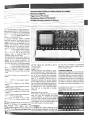
~
Advanceddisplay
facilities for realtimeanalysis
up
-cc,to 100MHz
Multi-sourcetriggering
'.""'cc'
~
c
c
c
Trigger view as fifth channel
-".,-
Simultaneousdisplay of MTBand DTB
Portable with battery operation for field use
c
--"
The PM 3264 offers a unique solution to
many timing problems in digital electronics.
Simultaneous display of 4 or 5 input signals
pro'.:' i "C! quick and convenient method for
reCiI:!; :n:llysis of digital signals both at
component and system level.
A versatile deflection system provides
many user-benefits. For example, any combination of up to five input signals and two
different modes can be selected by pushbuttons. The sensitivity of the channels
includes 2mV/div up to 400V per screen,
using the standard 1 : 10 attenuator probes.
A flf-!:';';' t'iggering system allows the main
an, -,
,-,j time bases to be triggered
inderJ'3n::Jently by any of the four input
channels. Also, an external trigger and
composite trigger are provided.
The alternate time base facility permits a
quick reference for magnified displays with
respect to the original waveform. The
multiple trace display demands a CRT with
very high light output. Philips has designed
a sr; , c;1t!Jbe with 17kV pda which provides
'a i::
'",n-adequate sharp, bright, spot.
With ai, lne foregoing facilities, the PM 3264
remains a typically compact, portable,
oscilloscope
which is also extremely
simple
to use.
The various facilities are summarized as
follows:
8 ff',." :I,annels to show signal relationSh,;: :ime
8 n1uiti-soufce triggering to add display
and the original four channels to give a
12-trace
display.
Trigger view
PM 3264 features the ultimate in multisourced triggering, with independent selection of main and delayed time bases from
any of the four channels plus composite,
line and external triggering on the maintime
base. It is therefore essential that the
relationship between the various displays
and the triggering signal is always clear and
this is provided by the trigger view facility.At
flexibility
8 trigger-view to relate triggering directly
to the four-channeldisplay
the touch of a button the actualtrigger signal
is displayed as a "fifth" channel, so that
there can be no possibility of display
. other features
like differential
displays ambiguity.
and Com
'
.
,
poslte
triggering
to extend
per-
formance
8 two time bases to allow signal detail to be
plck~d QIJtfrom the data stream
8, "'!i,o,',ldtive time base mode to allow
signal details to be directly related to data
stream
Moreover, facilities can be permutated. with
virtually no limitation. For example, main
and delayed
time
bases
can
be
independently triggered from any of the four
channels. Or the alternate time base mode
can be employed with a differential display
anyone of four channels to be displayed
against an X-input signal or against any of
the four vertical inputs.
Composite triggering
Single-channel triggering shows the exact
relationship between the displayed signals.
Composite triggering, however, allows signals that are not related in time or phase to
be displayed and compared.This facility can
be used in a variety of ways, for example
rise times or waveform aberrations can be
compared and measured regardless of the
All channelscan be invertedand combinedfor
obtaining
differential
displays.
The oscillogram shows how noise is suppressed by
addItion of two balanced signals displayed on channel
A and -8,
Alternate
time base mode
This mode is obtained simply by pushing
both the main and delayed time base
controls together. It enables the delayed
time base signal details to be displayed at
the same time as the intensified main time
base signals. In this way signal details can
be direct7yrelated to the data stream.
x-v displays
x-v displays are further evidence of the
advanced display capability of the PM 3264.
The independent triggering facilities allow
Ti
0
Sf
51
b.
m
At
::
::
Ac
r,
l
4-channel display with trigger view showing relationship of all signals to the external triggering source
Note the high light output levels
Fully
independent
triggering
allows
delayed
time
base
to be set to trigger on channel A, which allows detailed
.t
investigation at any time base speed
t
time span between signals or the frequency
CRT
Logic triggering too
The PM 3264 is the ideal compliment to a
logic analyzer since it shows realtime
relationships and signal details, such as
glitches, in their actual, analog waveform.
battery pack.
In
0
Dl
81
M,
relationship.
Very easy operation
PM 3264 is a highly sophisticated instrument but the front panel could not possibly
be simpler or more logical. Channel selection is made, for example, directly above the
relevant channel controls. Trigger selection
;or main and delayed time bases is also
logically grouped. This simplifies and
speeds up measurements and allows the
oscil1oscope to be used for virtually all applications and production testing.
In addition the PM 3264 is light, easy to
transport and hence ideal for field work, a
facility that can be extended via the optional
I.
Tr
In
L ...
Type
Philips rectangular domed mesh-type lube with 17kV
acceleration potential and metal-backed phosphor
Screen type
P31 (GH phosphor
standard)
Useful screen area
a x 10div of full centimeters
Horizontal deflection can be obtained from either the
main time base or the delayed time base or a combina.
tion of the two, or from the signal source selected for
X-deflection
In this case X-V diagrams can be displayed using A, B,
C, or D the EXT connector or the Line as a signal
source
Horizontal display modes
- Main time base
-
Main time base intensltled by delayed time base
Delayed time base
Main time base and delayed time base simultaneously displayed (alternate)
ouSly variable
- X-Yoperation with X-deflection by AoSoCoD tine or
Ext source
HORIZONTAL AMPLIFIER
Le
1m
Ex
Trl
II
Graticule
Internal graticule with centimeter divisions and 2mm
subdivisions along the central axes
10% and 90% lines are indicated.lliuminationcontinu-
VERT/CAL
ORYoM/SI
-
51
+
-
Response
E
Tri
DC
AC
Ex
1 t.,
DC 0 Hz..l00 MHz (35 MHz at 2mV)
AC 7 Hz 100 MHz
Respon',~
DC.2MHz (-3dB)
Me
401
Risetime
35ns
Deflection coefficient
50mV/div using EXT connector
Un calibrated continuous control 1 : > 3.
Tri!
Be
When A, B, C or Dare used, sensitivity is 2mV...5V/div
DE
Deflection coefficients
2mV5V/div
In steps in 1-2-5 sequence
Uncalibrated
control between steps 1 : > 25
continuous
Display modes
- Channel Ao B, C or D
-
A + B, C + Do
Trigger view
any combination of these channels
Multiple display chopped at1 MHz or Alternate
Any channel may be inverted except Trigger view
CMRR
>1001 upto2MHz
> 201at50MHz
accuracy
Yrl!
Int.
Fol
TIt.
Phase error
3' at 100kHz
MAIN TIMEBASE MODES"
'" c
-
Auto
- Triggered (RC time 100ms)
- Singleshot
Time coefficient
Input impedance
1 MO:t 2% in parallel with 15pFapprox. RC1ime,AC
coupled 22ms
Maximum input voltage
400VDC+ AGp" derating above 500kHz
Maximum deflection
Un distorted deflection
range 1Sdiv.
Measuring
j:3%
of 24div. up to 35MHz
Shift
Signal delay
15ns visible delay
Trigger view
Display: External or internal trigger signal
Deflection coefficient external: 100 mV/div
Trigger point: Screen centre :t 0.3div
Time delay between vertical input and external input:
3ns
1s..50ns/dlv
in 23 calibrated steps, in 1-2-5
sequence. Uncalibrated continuous control between
steps (with UNCAL warning lamp should delayed time
base be set out of calibration). x 10 magnifier extends
max. sweep rate to 5ns/div.
Accuracy
:t 2% (+20°C..+30°C)
:t 3% (+ 5"C+40°C)
Additional error for magnifier :t 1%
Ct
Ca:
3V,
Cal
6m
Z-I
Inp
DC
disi
Inp
10k
Variable hold-off
Sweep hold-off time can be increased by a factor of 10
Me:
50\
QELAYEDTIMEBASE
Ref
35r
Modes
Delayed time base starts, either immediately after the
delay time or, upon arrival of the first trigger pulse after
the delay time.
PO
Lln,
AC
DC
Time coefficients
O.5s..50ns/div. in 22 calibr~ted steps, 1-2-5
sequence. Uncalibrated continuous control between
stepS, (with UNCAL warning lamp should main time
base be set out of calibration). x 10 magnifier extends
max. sweep rate to 5ns/div.
Power consumption
SOW at nominallin~ voltage
Dimensions and weight
(wxhxd) 316x 154 x 460mm
(12.4 x 6.1.x18-in)
11kg (24Ib)
,.,~uracy
.. of"(+20.C...+30.C)
~~Et!~A8IL/TIESj,
::3'/"(+
S.C...+4Q.C)
Additional.error
for magnifier:t
1%
Calibrated sweep delay
ContinuouS calibrated control between 0 and 10 x main
time base setting.
Incremental
delay time accuracy
02% typical
Ambient temperatures
Delay time jitter
Better than 1 :30 000
Rat~d range of use:
Limits for operation:
Storage and transport:
-!ME BASE TRIGGERING
+S.C to + 40.C
-10.C to + SS.C
-SS.C to + 7S.C
Altitude
Operating: to 5000rn (15 0001t)
Non-operating: to 15 OOOrn(45 0001t)
Ir'9g"r source
1nternalA, 8, C, D Composite, line, External
Slope
+or-
Humidity
21 days cyclic damp heat 25.C...40.C R.H. 95%
L8velr8ng~
Internal:24div
External+ 1.2Vto
- 12V
30g: half sinewave sl1ock af 11ms duration:
2 shocks per direction for a total of 12 shocks
Trigger sensitivity
---
30MHz
100MHz
- ---"",
1.5div
OSdiv
c
-'.+
SOmV
Ex!
Trigger
The environmental data is valid only if the instrument is
checked in accordance with the official checking
procedure. Details of these procedures
and failure
criteria are supplied on request by the PHILIPS
organization in your country, or by PHILIPS TEST
AND MEASUREMENT DEPARTMENT, EINDHOVEN,
THE NETHERLANDS.
Vlbratiol1
Vibrations in three directions with a maximum 01 15min
per direction; 5...55 Hz and amplitude 010. 7mmp.pand
49 max acceleration
Unit mounted on vibration table without shock absorb-
150mV
--c
"""
ing material
Recovery time
Operates within 30 minutes coming from -100 C soak,
going into 60% relative humidity at +200C room condi-
coupling
DC DC",full bandwidth
AC: 100Hz ,lull bandwidth
lions.
Ext. trigger input impedance
1 M f! :t 2% in parallel with 15pF approx
Maximum
"""
allowable
input
Electromagnetic
interference
Meets VDE 0871 and VDE 0875
voltage
(Grenzwertklasse B)
"cc +AC pk
Safety
Safety class I according to lEG 348
;;'=-.,,;!rjltter
Bailer than OSns
-~
-
-
--~-
D-~~~EP_TI':1~
~~~~!!!~G~~'YG,j,"
Trigger source
Internal A, B, C or 0
For Slope, Level range and Sensitivity
TIME BASE TRIGGERING
see MAIN
CAUBRATION
Front cover with storage space
Operating and service manual
BNC-banana adapter
Contrast filter
4 x 10: 1 attenuator probe PM 8928/00
Collapsible viewing hood
Cal terminal - BNC adapter
options
Universal Euro 220V/16A Option 001
North American 120V/15A Option 003
United Kingdom 240V/15A Option 004
PM 8924/00 Passiveprobe 1: 1 (1.5m)
current
6mAp.p:t 2% square wave
PM 8924/20
PM 8931/00
Input
TTLcompatible.
Passive probe 1 : 1 (2.5m)
PM 8928/00 HFpassiveprobe10:1 (1.5m)
?-~ODUI:.ATION
DC-coupled.
display
100MHz oscilloscope
Power options:
Philips oscilloscopes
are normally
delivered in accordance with local power requirements. If an alternative power option is required. the
instrument can be supplied fitted with a different power
setting and power cord option.
In such cases,
purchase orders should specify one of the following
OPTIONAL ACCESSORIES
';,.-,-ated voltage
3":0' '" 1% square wave
Calibrated
ACCESSORIES SUPPLIED
PM 3264
"HIGH"
levelbianksthe
Passive probe 100: 1; 2pF (1.5m)
PM 8960103 19-in rackmount ~dapter
PM 9381
Oscilloscope camera
PM 9366
Collapsible viewing hood
;"""t impedance
Maximum
50V
input voltage
Response
35ns
lime
POWER
Line voltages and frequencies
AC 100..127V and 220 240V. 46.440Hz
)C250350V
PM 8980
PM 8991
Oscilloscope
PM 8992/66
Accessory pouch
PM 8999
Stand
trolley
;,;",...
c~