1
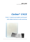
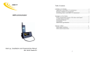
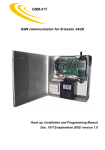
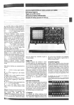
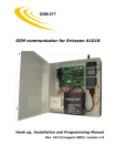
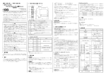
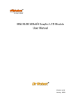
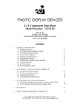
Cardax N32R
Network Interface for
Access Control System
INSTALLATION MANUAL
Doc. 20106/03.06/Versiunea F
Contents
1
2
INTRODUCTION ................................................................................................................................................ 3
CARDAX N32R ................................................................................................................................................... 4
2.1
NETWORK INTERFACE MODULE BOARD ................................................................................................... 5
2.2
RESOURCES ............................................................................................................................................... 5
3 CONNECTIONS .................................................................................................................................................. 5
3.1
POWER SUPPLY.......................................................................................................................................... 5
3.2
INPUTS and OUTPUTS ............................................................................................................................... 6
3.2.1
Wiring a NC Lock Device..................................................................................................................... 6
3.2.2
Wiring a NO Lock Device .................................................................................................................... 7
3.2.3
Details regarding the four relay outputs on the network interface module CARDAX N32R ............... 7
3.2.4
Wiring magnetic sensor and request to exit button ........................................................................... 8
3.3
CARD READER INTERFACE ........................................................................................................................ 8
3.4
COMMUNICATION.................................................................................................................................... 10
3.4.1
Wiring the module Cardax N32R to the serial bus RS485 ................................................................ 10
4 BOARD SETTINGS ........................................................................................................................................... 11
4.1
JUMPERS .................................................................................................................................................. 11
4.1.1
Description ........................................................................................................................................ 11
4.2
DIP-SWITCHES......................................................................................................................................... 11
4.2.1
Description ........................................................................................................................................ 11
4.3
LEDS FOR STATUS NOTIFICATION.......................................................................................................... 12
Table list
Table
Table
Table
Table
Table
3-1:
3-2:
3-3:
3-4:
4-1:
Power supply signals............................................................................................................................... 5
I/O signals............................................................................................................................................... 6
Card reader interface signals .................................................................................................................. 8
Communication interface signals .......................................................................................................... 10
Jumper functions................................................................................................................................... 11
Figure list
Figure
Figure
Figure
Figure
Figure
Figure
Figure
Figure
Figure
Figure
Figure
2.1
2.2
3.1
3.2
3.3
3.4
3.5
3.6
3.7
3.8
3.9
Cardax N32R ........................................................................................................................................... 4
Schematic view of the network interface module board N32R ............................................................... 5
Power supply signals ............................................................................................................................... 5
I/O signals ............................................................................................................................................... 6
Wiring NC lock device.............................................................................................................................. 7
Wiring NO lock device ............................................................................................................................. 7
Wiring magnetic sensor and request to exit button................................................................................ 8
Card reader interface signals .................................................................................................................. 8
Communication interface signals........................................................................................................... 10
Wiring the network interface module to the serial bus RS485.............................................................. 10
Connecting the control access module Cardax on the RS485 serial bus .............................................. 10
2
1 INTRODUCTION
Terms
Central Unit: Defines equipment able to communicate to up to 32 network interface modules. It stores the
system database and the card codes in the system. The central unit for CARDAX system is represented by the
Cardax N32C module.
Network Interface: Defines the equipment able to control and monitor an access point on the basis of
decisions communicated by the central unit. In Cardax system the network interface modules are Cardax N32R
and Cardax N32KP. As a detail, the central unit PCB of Cardax N32C incorporates the functions of a Cardax
N32R module.
RIM – Reader Interface Module: Interface with the card reader, defining equipment able to translate the
signals from the card (code) reader. In Cardax system such interfaces are present on the central unit Cardax
N32C and on each Cardax N32R network interface module as well.
Access Point: It’s a zone allowing access in a supervised area. Each access point is controlled by a network
interface module.
PC – Personal Computer: The monitoring software, the set up software and the presence software as well
run on the PC. Data received by the central unit Cardax N32C are sent to PC as events. On the basis of these
events, there can be generated reports and presence files.
A generic view of CARDAX system is shown in figure1.1:
ACCESS
CONTROL
SYSTEM
CARDAX
RS-485
Cardax N32C
Cardax N32R
Cardax N32KP
Figure 1.1 Generic view of CARDAX control access system
In the picture above you can see the main elements of CARDAX Access Control system.
A. Cardax N32C is the system central unit.
Functions:
- keeping the system data base (users, access zones, schedules, type of readers);
- granting/denying access into the supervised access points upon set up criteria (zones, schedules, validity
code period, antipassback, etc.);
- keeping the event log;
- communication with the network interface modules in the access points (RS485 serial interface);
3
- communication with the PC (RS232 serial interface).
B. Cardax N32R is a network interface module that can assume two magnetic or proximity card readers to work
with. The module controls a single access point in both directions (entry/exit). On demand, an request to
exit button could be used in addition to the card readers.
C. Cardax N32KP is a network interface module that accepts keypad codes. As opposed to Cardax N32C and
Cardax N32R, it does not incorporate a stabilized 12V power supply. The module controls a single one-way
access point. To control the access point in both directions, two such modules will be mounted at same
access point.
The functions of Cardax N32R or Cardax N32KP network interface modules are:
- Detection of access point status (door, turnstile, etc.) by means of a magnetic sensor (or any N.O. contact);
- Detection of request to exit button trigger (if necessary);
- Managing the lock device;
- Communication with central unit Cardax N32C;
- Reading the access code from card readers or keypads;
- Relay triggering upon events issued at the access point (Forced Door, Door propped, etc.).
2 CARDAX N32R
Please, verify if your package contains:
- Metallic box
- Network interface module
- 14V / 3A transformer
- fuse base
- 250mA fuse
Figure 2.1 Cardax N32R
The installation procedure has two steps:
1. Physical connection of the electric cables.
2. Network interface module configuration by means of jumpers and switchers.
1. Cable connection:
There are four signal groups:
A. Power supply
B. Card reader interface
C. Input/Output signals for the access point interface
i. Door sensor
ii. Request to exit button
iii. Lock device
iv. Optic-acoustic alert in case of different events
D. Serial communication interface RS485
Cables:
1. For power supply connection (220Vac) – 3-wire cable: 1 – 1.5mmp
2. Card reader cable: cable 0.22mmp + shield (8 wires). The shield should be connected to GND.
3. Request to exit button and door sensor: 0.22mmp cable
4. Lock device: cable 0.5 – 0.7mmp
5. RS485 serial interface: 4-wire twisted pair + shield or UTP cable, category 5 shielded.
2. Network interface module configuration
The following parameters could be hardware programmed:
A. The address of card reader interface
4
B. RS 485 end of line resistor.
C. Card readers’ power supply
+
2.1 NETWORK INTERFACE MODULE BOARD
+
+
+
3
12V 5V
1
12V 5V
1
3
+
+
+
Figure 2.2 Schematic view of the network interface module board N32R
2.2 RESOURCES
-
4 relay outputs to trigger the lock device and various notifications;
request to exit button input;
magnetic door sensor input;
12V / 1.5A lock device power supply;
RS 485 serial interface for central unit communication;
Monitoring and diagnosis LEDs.
3 CONNECTIONS
3.1 POWER SUPPLY
PLUS MINUS
~
~ GND 12V N1 N2 G S COM DS
RE NO C NC NO C NC NO C NC NO C NC 2A
3A LED BP
_
+ 2B
3B LED BP
_
+
Figure 3.1 Power supply terminals
Table 3-1: Power supply signals
PIN NUMBER
1
2
3
4
5
NAME
~ 14V (1)
~ 14V (2)
GND
+12V
FUNCTION
14V AC SUPPLY
EARTH GROUND
14V AC SUPPLY
GROUND
DC POWER SUPPLY
REMARKS
Connectors for lock device power
supply.
Order of connections:
- Red wire (+) to “+” plug of the battery.
- Black wire (-) to “–” plug of the battery.
RED power led should light.
5
-
Transformer wires should be connected to “~” connectors.
The RED power led will be off while the YELLOW led will light.
The connector in the middle of “~” connectors will be grounded together with the metallic case.
Please, verify the voltage between 12V and GND connectors is about 13.6 volts. This value indicates a voltage
high enough for charging the battery. If necessary, adjust this value by means of the potentiometer located on
the left upper side of the board.
NOTE: If AC power is applied before connecting the battery, the RED led will not turn on when battery power is
applied.
3.2 INPUTS and OUTPUTS
PLUS MINUS
~
~ GND 12V N1 N2 G S COM DS
RE NO C NC NO C NC NO C NC NO C NC 2A
3A LED BP
_
+ 2B
3B LED BP
_
+
Figure 3.2 I/O signals
Table 3-2: I/O signals
PIN NUMBER
NAME
FUNCTION
Common for door sensor and
request to exit button
9
COM
10
DS
DOOR SENSOR input
11
RE
REQUEST TO EXIT BUTTON input
(REQUEST EXIT)
12
13
14
15
16
17
18
19
20
21
22
23
NO
C
NC
NO
C
NC
NO
C
NC
NO
C
NC
ADDITIONAL REMARKS
Internally wired at 12V, not
to GND
The sensor or any other NC
contact is connected
between DS and COM
The button or any other NO
contact is connected
between RE and COM
EXTERNAL SIGNALS OF
12V/10A MAIN RELAY
Main relay, triggers the lock
device
EXTERNAL SIGNALS OF
SECONDARY RELAY 1 12V/1A
Relay output destined to
Forced door event
EXTERNAL SIGNALS OF
SECONDARY RELAY 2 12V/1A
Relay output destined to
Propped door event
EXTERNAL SIGNALS OF
SECONDARY RELAY 3 12V/1A
Relay output destined to
inhibit other sensors during
the access process
3.2.1 Wiring a NC Lock Device
NC Lock devices are normally activated (powered). Their power supply should be cut to release the access
during the access time. These devices current consumption is under 1A. When power supply fails, the access
point is released.
6
~
~ GND 12V N1 N2 GS COM DS RE NO C NC NO C NC NO C NC NO C NC 2A 3A LED BP _
+ 2B 3B LED BP
_
+
NORMALLY CLOSED
ELECTROMAGNETIC LOCK
Figure 3.3 Wiring NC lock device
3.2.2 Wiring a NO Lock Device
NO Lock devices are normally deactivated (not powered). Their power supply should be connected to release
the access during the access time. Sometimes the device is triggered with train of impulses. These devices’
current consumption could exceed 2-3A but only for a while. When power supply fails, the access point is
locked.
~
~ GND 12V N1 N2 GS COM DS RE NO C NC NO C NC NO C NC NO C NC 2A 3A LED BP _
+ 2B 3B LED BP
_
+
NORMALLY OPEN
ELECTROMAGNETIC LOCK
Figure 3.4 Wiring NO lock device
Note: The diode is 1N4001 or equivalent.
3.2.3 Details regarding the four relay outputs on the network interface module CARDAX
N32R
1. MAIN RELAY (12V/10A) is destined, generally speaking, to the lock device (or for turnstile command, etc.).
The type of the lock device (N.O. or N.C. electromagnetic locks, turnstiles, etc.) assumes a specific relay
period to be programmed.
The Main Relay time could be programmed through the PC. If this time has value 0, then the relay will be
triggered with two short impulses. The main relays commutes on a valid access command (valid card or
request to exit button push) and releases when the relay time expires or if the door sensors sees “door
opened” and then “door closed” during this period of time.
The default main relay time is 5 seconds.
2. SECONDARY RELAY 2 (“FORCED DOOR” - 12V/1A). This relay commutes when Forced Door event occurs.
After detecting the door being opened (by means of a magnetic sensor) without authorization (without a
valid card code or without pressing the request to exit button), the relay will commute for a predefined time
of 20 seconds. The relay releases before the time expired if a valid code (card) is entered. The relay could
be connected to a burglary control panel or to a siren powered from the N32R power supply (siren
consumption < 300mA) or from an external power supply.
7
The relay is usually connected to a 24-hour zone of a burglary control panel.
3. SECONDARY RELAY 3 (“DOOR LEFT OPEN” - 12V/1A). This relay commutes when Door Left Open event
occurs. The event is generated when the door sensor detects “door open” even after the access time
(entry/exit time) expired. The relay releases only when the sensor detects “door closed”. The relay can be
connected to a burglary control panel, to an acoustic device (buzzer) or optic device (flash, LED).
The relay is usually connected to a “chime zone” of a burglary system.
4. SECONDARY RELAY 4 (“INHIBIT” - 12V/10A). The relay is activated together with the main relay and
releases upon door closing following a valid access process. The relay could be used to short (inhibit) a
sensor of a burglary control panel during the access time.
Warning: do not use the same relay for both the burglary control panel and the access control system.
Note: When 2-way turnstiles with separate triggering on each way are used, this relay can be
programmed to function as the main really. The main relay actions for one way, while the „INHIBIT” relay
actions for the other. To work this way, the module Cardax N32R should be equipped with other firmware
version purchased only on special request.
3.2.4 Wiring magnetic sensor and request to exit button
~
~ GND 12V N1 N2 GS COM DS RE NO C NC NO C NC NO C NC NO C NC 2A 3A LED BP _
+ 2B 3B LED BP
_
+
RTE
Figure 3.5 Wiring magnetic sensor and request to exit button
Note:
The magnetic sensor could be replaced by any NORMALLY CLOSED device.
The request to exit button could be replaced with any NORMALLY OPEN device.
Attention: COM pin is internally connected to 12V, not to GND.
3.3 CARD READER INTERFACE
~
~ GND 12V N1 N2 G S COM DS RE NO C NC NO C NC NO C NC NO C NC 2A
3A LED BP
_
+ 2B 3B LED BP
_
+
Figure 3.6 Card reader interface signals
Table 3-3: Card reader interface signals
For the communication standard ISO TRACK 2 (usually used by magnetic card readers):
PIN
NUMBER
24
25
26
27
28
29
30
31
32
33
34
35
NAME
2A
3A
LED
BP
+
2B
3B
LED
BP
+
–
FUNCTION
STROBE IN reader
NDATA IN reader
LED control IN reader
Beeper control IN reader
5/12V power supply IN reader
GND power supply IN reader
STROBE OUT reader
NDATA OUT reader
LED control OUT reader
Beeper control OUT reader
5/12V power supply OUT reader
GND power supply OUT reader
REMARKS
If readers allow that
If readers allow that
Power supply is configured
by means of JP4
If readers allow that
If readers allow that
Power supply is configured
by means of JP5
8
For the communication standard WIEGAND (usually used by proximity card readers):
PIN
NUMBER
24
25
26
27
28
29
30
31
32
33
34
35
NAME
2A
3A
LED
BP
+
2B
3B
LED
BP
+
–
FUNCTION
DATA1 IN reader
DATA0 IN reader
LED control IN reader
Beeper control IN reader
5/12V power supply IN reader
GND power supply IN reader
STROBE/DATA1 OUT reader
NDATA/DATA0 OUT reader
LED control OUT reader
Beeper control OUT reader
5/12V power supply OUT reader
GND power supply OUT reader
REMARKS
If readers allow that
If readers allow that
Power supply is configured
by means of JP4
If readers allow that
If readers allow that
Power supply is configured
by means of JP5
The device may interface both ISO TRACK 2 and WIEGAND readers. IN THE First case, the signals to
communicate the card code are STROBE and NDATA, in the second case the signals are DATA1 and DATA0. If
two readers are connected to the module Cardax N32R, they should be of the same type.
If the reader has no LED and/or BEEP controllable signals, then EXTERNAL LEDs or buzzers could be attached.
LED and BP are open collector NPN outputs at the voltage configured on JP4 and JP5. When an EXTERNAL
LED/BUZZER is used, then:
- LED cathode is wired to “LED” signal.
- LED anode should be connected to “+” terminal through 470 ohm resistor if the reader is 5V supplied or
1.2K if the reader is powered 12V.
- “–” pin of the beeper is wired to “BP”.
- “+” pin of the beeper should be connected to “+” terminal through 470 ohms resistor if the reader is 5V
supplied or 1.2K if the reader is powered 12V.
Notes:
The readers’ power supply is programmed by means of JP4 and JP5 (see section 4.1).
When two readers are mounted on the same access point, then by default the terminals 2A and 3A correspond
to the ENTRY reader, and the terminals 2B and 3B correspond to the EXIT reader. This configuration could be
inverted with an option of the access control software.
Distance limits in between the readers:
1. Magnetic readers do not generate distance problems. They may be mounted as near as you wish.
2. The proximity readers are of two types: with amplitude modulation and with frequency modulation.
3. The frequency modulation ones do not generate problems regarding distance between them.
The amplitude modulation ones should be tested before being mounted as regards to the minimum
distance between them. The readers should be powered and placed at different distances from one
another. Notice how they influence each other. If the distance is too small, then the readers either do not
“see” the card at all, or they read the card from a very small distance.
Another factor that influences the reading distance is the mounting surface. As for the proximity readers, the
metal mounting surfaces reduce substantially the reading distance. If you cannot avoid metallic surfaces, then
place a piece of plastic (10 mm thick) between the reader and metal.
9
3.4 COMMUNICATION
~
~ GND 12V N1 N2 G S COM DS RE NO C NC NO C NC NO C NC NO C NC 2A
3A LED BP
_
+ 2B 3B LED BP
_
+
Figure 3.7 Communication interface signals
Table 3-4: Communication interface signals
PIN NUMBER
NAME
6
N1
7
N2
8
GS
FUNCTION
RS485 serial bus
REMARKS
Wired to N1 pin of the next
equipment on the bus
Wired to N2 pin of the next
equipment on the bus
Wired to GS pin of the next
equipment on the bus***
*** GS pin is used when the distance between equipments is long. The signal equalizes the potentials on the
RS485 bus between the two equipments.
3.4.1 Wiring the module Cardax N32R to the serial bus RS485
~
~ GND 12V N1 N2 GS COM DS RE NO C NC NO C NC NO C NC NO C NC 2A 3A LED BP _
+ 2B 3B LED BP
_
+
SERIAL BUS RS 485
Figure 3.8 Wiring the network interface module to the serial bus RS485
Notes:
1. The maximum distance between the connector and the RS485 bus is 8 cm long to prevent possible
reflections
2. If the network interface module is at one end of the serial bus then the jumpers JP3 and JP4 should be
closed
3. The cable should be RS485 type (120 ohm impedance) or at least FTP type (100 ohm impedance, shielded
– foil)
3. If the cable is shielded laced, the shield lace will be connected at the GND signal at one end of the serial
bus.
The connection of several modules on the RS485 bus is shown in the figure below. The jumpers should be
closed on the bus ends (red colored).
12V GND
GS N1 N2
GS N1 N2
GS N1 N2
GS N1 N2
SHIELD
Figure 3.9 Connecting the control access module Cardax on the RS485 serial bus
-
10
4 BOARD SETTINGS
4.1 JUMPERS
The board JUMPERS have the following functions:
Table 4-1: Jumper functions
NAME
JP1
JP2, 3
JP4, 5
RESOURCE CONTROL
Board reset
RS485 end of line
Control for card reader power supply
FACTORY POSITION
OPEN
OPEN
CLOSE 1-2 (12V)
4.1.1 Description
JP1 (RESET)
Press this pushbutton for one second if the system blocks for any reason.
JP2 and JP3
When closed, these jumpers control the RS485 signal protection. Short circuit these jumpers if Cardax N32R
module is at one end of the bus.
JP4 and JP5
They select magnetic or proximity card reader power supply.
In 1-2 closed position, the power supply is 12Vdc.
In 2-3 closed position, the power supply is 5Vdc.
4.2 DIP-SWITCHES
SW1 establishes the address of the card reader interface.
4.2.1 Description
SW1
This 8 position DIPSWITCH is used to establish the address of the card reader interface. To set this address, you
have to follow this procedure:
- Set the board address according to the table 4-2;
- Put SW1.1 ON
- Put SW1.2 ON
- Push the RESET button for 5 seconds
- Put SW1.1 OFF
- Put SW1.2 OFF
- At this moment, the activation of the newly configured network interface module can be noticed on the
PC installed access control software.
Table 4-2: RIM address
ADDRESS 4
00
OFF
01
OFF
02
OFF
03
OFF
04
OFF
05
OFF
06
OFF
07
OFF
08
OFF
09
OFF
10
OFF
11
OFF
12
OFF
13
OFF
14
OFF
15
OFF
configuration
5
6
7
OFF OFF OFF
OFF OFF OFF
OFF OFF ON
OFF OFF ON
OFF ON OFF
OFF ON OFF
OFF ON ON
OFF ON ON
ON OFF OFF
ON OFF OFF
ON OFF ON
ON OFF ON
ON ON OFF
ON ON OFF
ON ON ON
ON ON ON
8
OFF
ON
OFF
ON
OFF
ON
OFF
ON
OFF
ON
OFF
ON
OFF
ON
OFF
ON
ADDRESS
16
17
18
19
20
21
22
23
24
25
26
27
28
29
30
31
4
ON
ON
ON
ON
ON
ON
ON
ON
ON
ON
ON
ON
ON
ON
ON
ON
5
OFF
OFF
OFF
OFF
OFF
OFF
OFF
OFF
ON
ON
ON
ON
ON
ON
ON
ON
6
OFF
OFF
OFF
OFF
ON
ON
ON
ON
OFF
OFF
OFF
OFF
ON
ON
ON
ON
7
OFF
OFF
ON
ON
OFF
OFF
ON
ON
OFF
OFF
ON
ON
OFF
OFF
ON
ON
8
OFF
ON
OFF
ON
OFF
ON
OFF
ON
OFF
ON
OFF
ON
OFF
ON
OFF
ON
11
After the configuration, please write the address on a label and stick it on the case or on the board.
That will be useful if the system is extended, modified or repaired.
Note: As opposed to the previous types, the address of this module can be found out by watching
the configuration of the switch set, by reading their positions from left to right (On=1, OFF=2).
4.3 LEDS FOR STATUS NOTIFICATION
Table 4-3: LED signification
NAME
DL1
DL2
DL3
DL4
DL5
DL6
DL7
DL8
COLOR
YELLOW
RED
GREEN
RED
GREEN
GREEN
GREEN
GREEN
FUNCTIONING
ON, if 14Vac is present
ON, if board power supply is battery backup only
ON, when the serial transmission signal RS485 from the module is present
ON, when the serial transmission signal RS485 from the module is present
ON, while Relay 1 is activated
ON, while Relay 2 is activated
ON, while Relay 3 is activated
ON, while Relay 4 is activated
An innovative product manufactured and distributed by:
ROEL electronics
S.A.
27-29 Calimachi St.,
023496 Bucharest,
Tel.: 4021/204.47.00, Fax: 4021/242.20.30,
E-mail: [email protected], www.roel.ro
12