1
GO TO THIS MANUAL'S TABLE OF CONTENTS
RETURN TO CD-ROM TABLE OF CONTENTS
Technical
Service
Manual
Part Number: 4116029
Rev: C
Date: 11 December 2000
© 2000 Draeger Medical, Inc.
Fabius®
Anesthesia System
RETURN TO THIS MANUAL'S TABLE OF CONTENTS
RETURN TO CD-ROM TABLE OF CONTENTS
RETURN TO CD-ROM TABLE OF CONTENTS
Fabius® Service Manual Table of Contents
Summary of what's new in Revision C
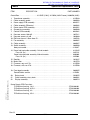
DESCRIPTION
PAGE
SECTION 1:
Introduction . . . . . . . . . . . . . . . . . . . . . . . . . . . . . . . . . . . . . . . . . . . . . . . . . . . . . . . . . . . . . . . 1-1
SECTION 2:
Fabius Function Description
1. General Information about Fabius. . . . . . . . . . . . . . . . . . . . . . . . . . . . . . . . . . . . . . . . . . 2-1
2. Fabius Function Diagrams . . . . . . . . . . . . . . . . . . . . . . . . . . . . . . . . . . . . . . . . . . . . . . . 2-4
3. Function Diagram (2-gas version). . . . . . . . . . . . . . . . . . . . . . . . . . . . . . . . . . . . . . . . . . 2-7
4. Function Diagram (3-gas version). . . . . . . . . . . . . . . . . . . . . . . . . . . . . . . . . . . . . . . . . . 2-8
5. Function Description of the Gas Box . . . . . . . . . . . . . . . . . . . . . . . . . . . . . . . . . . . . . . . 2-9
6. Compact Breathing System COSY/Circle System 9 . . . . . . . . . . . . . . . . . . . . . . . . . . . 2-13
7. Ventilation Unit . . . . . . . . . . . . . . . . . . . . . . . . . . . . . . . . . . . . . . . . . . . . . . . . . . . . . . . 2-33
8. Patient System . . . . . . . . . . . . . . . . . . . . . . . . . . . . . . . . . . . . . . . . . . . . . . . . . . . . . . . 2-38
9. Electronics Block Diagram . . . . . . . . . . . . . . . . . . . . . . . . . . . . . . . . . . . . . . . . . . . . . . 2-41
10. Control Box . . . . . . . . . . . . . . . . . . . . . . . . . . . . . . . . . . . . . . . . . . . . . . . . . . . . . . . . . . 2-42
11. FiO2 Measurement . . . . . . . . . . . . . . . . . . . . . . . . . . . . . . . . . . . . . . . . . . . . . . . . . . . . 2-57
12. Flow Measurement . . . . . . . . . . . . . . . . . . . . . . . . . . . . . . . . . . . . . . . . . . . . . . . . . . . . 2-58
13. Anesthetic Vaporizer “Vapor 19.n” . . . . . . . . . . . . . . . . . . . . . . . . . . . . . . . . . . . . . . . . 2-59
SECTION 3:
Fabius Repair Instructions
1. Service Strategy for Fabius . . . . . . . . . . . . . . . . . . . . . . . . . . . . . . . . . . . . . . . . . . . . . . . 3-1
2. Fabius Versions. . . . . . . . . . . . . . . . . . . . . . . . . . . . . . . . . . . . . . . . . . . . . . . . . . . . . . . . 3-3
3. Fabius Assemblies . . . . . . . . . . . . . . . . . . . . . . . . . . . . . . . . . . . . . . . . . . . . . . . . . . . . . 3-4
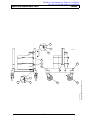
4. Fabius Assemblies (rear view) . . . . . . . . . . . . . . . . . . . . . . . . . . . . . . . . . . . . . . . . . . . . 3-6
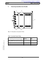
5. Removing Assemblies from Gas Box . . . . . . . . . . . . . . . . . . . . . . . . . . . . . . . . . . . . . . . 3-7
6. Debug Mode (software 1.00). . . . . . . . . . . . . . . . . . . . . . . . . . . . . . . . . . . . . . . . . . . . . . 3-8
7. Debug Mode (software 2.00). . . . . . . . . . . . . . . . . . . . . . . . . . . . . . . . . . . . . . . . . . . . . 3-10
8. “Ventilator” VEN Display Field . . . . . . . . . . . . . . . . . . . . . . . . . . . . . . . . . . . . . . . . . . . . 3-13
9. “Monitor” MON Display Field. . . . . . . . . . . . . . . . . . . . . . . . . . . . . . . . . . . . . . . . . . . . . 3-14
10. “EEPROM” (EEP) Display field . . . . . . . . . . . . . . . . . . . . . . . . . . . . . . . . . . . . . . . . . . . 3-16
11. Error Log . . . . . . . . . . . . . . . . . . . . . . . . . . . . . . . . . . . . . . . . . . . . . . . . . . . . . . . . . . . . 3-18
12. DrägerService Mode (software 1.00) . . . . . . . . . . . . . . . . . . . . . . . . . . . . . . . . . . . . . . 3-21
13. DrägerService Mode (software 2.00) . . . . . . . . . . . . . . . . . . . . . . . . . . . . . . . . . . . . . . 3-23
14. General Information about the Control Box. . . . . . . . . . . . . . . . . . . . . . . . . . . . . . . . . . 3-25
15. Gas Box . . . . . . . . . . . . . . . . . . . . . . . . . . . . . . . . . . . . . . . . . . . . . . . . . . . . . . . . . . . . 3-81
16. COSY Compact Breathing Sustem Components . . . . . . . . . . . . . . . . . . . . . . . . . . . . . 3-88
17. Circle Absorbtion System Components . . . . . . . . . . . . . . . . . . . . . . . . . . . . . . . . . . . . 3-96
18. General Information about the Flowmeter Block . . . . . . . . . . . . . . . . . . . . . . . . . . . . . 3-103
19. General Information about the ORC . . . . . . . . . . . . . . . . . . . . . . . . . . . . . . . . . . . . . . 3-108
Rev. A
i
RETURN TO THIS MANUAL'S TABLE OF CONTENTS
RETURN TO CD-ROM TABLE OF CONTENTS
Fabius®
Contents (continued)
PAGE
DESCRIPTION
20.
21.
22.
23.
24.
General Information about the Ventilator . . . . . . . . . . . . . . . . . . . . . . . . . . . . . . . . . .
General Information about the Uninterruptible Power Supply (option) . . . . . . . . . . . .
General Information about the Pneumatics . . . . . . . . . . . . . . . . . . . . . . . . . . . . . . . .
Patient System . . . . . . . . . . . . . . . . . . . . . . . . . . . . . . . . . . . . . . . . . . . . . . . . . . . . . .
Tubing Diagram . . . . . . . . . . . . . . . . . . . . . . . . . . . . . . . . . . . . . . . . . . . . . . . . . . . . . .
3-121
3-139
3-142
3-161
3-165
SECTION 4:
Test Certificate
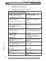
1. Unit, General . . . . . . . . . . . . . . . . . . . . . . . . . . . . . . . . . . . . . . . . . . . . . . . . . . . . . . . . . . 4-4
2. Circle system mount or compact breathing system . . . . . . . . . . . . . . . . . . . . . . . . . . . . 4-6
3. Control Box . . . . . . . . . . . . . . . . . . . . . . . . . . . . . . . . . . . . . . . . . . . . . . . . . . . . . . . . . . . 4-8
4. Gas Connections . . . . . . . . . . . . . . . . . . . . . . . . . . . . . . . . . . . . . . . . . . . . . . . . . . . . . 4-10
5. Cylinder Pressure Reducer. . . . . . . . . . . . . . . . . . . . . . . . . . . . . . . . . . . . . . . . . . . . . . 4-11
6. Cylinders . . . . . . . . . . . . . . . . . . . . . . . . . . . . . . . . . . . . . . . . . . . . . . . . . . . . . . . . . . . . 4-12
7. Lack of O2 Alarm . . . . . . . . . . . . . . . . . . . . . . . . . . . . . . . . . . . . . . . . . . . . . . . . . . . . . 4-13
8. Pressure Regulator . . . . . . . . . . . . . . . . . . . . . . . . . . . . . . . . . . . . . . . . . . . . . . . . . . . . 4-13
9. O2 Flush Valve . . . . . . . . . . . . . . . . . . . . . . . . . . . . . . . . . . . . . . . . . . . . . . . . . . . . . . . 4-14
10. Ejector Outlet . . . . . . . . . . . . . . . . . . . . . . . . . . . . . . . . . . . . . . . . . . . . . . . . . . . . . . . . 4-14
11. Secretion Aspirator (optional) . . . . . . . . . . . . . . . . . . . . . . . . . . . . . . . . . . . . . . . . . . . . 4-14
12. AGS System . . . . . . . . . . . . . . . . . . . . . . . . . . . . . . . . . . . . . . . . . . . . . . . . . . . . . . . . . 4-16
13. Vapor plug-in system housing section . . . . . . . . . . . . . . . . . . . . . . . . . . . . . . . . . . . . . 4-16
14. Safety Valve, flowmeter unit . . . . . . . . . . . . . . . . . . . . . . . . . . . . . . . . . . . . . . . . . . . . . 4-16
15. Leak test . . . . . . . . . . . . . . . . . . . . . . . . . . . . . . . . . . . . . . . . . . . . . . . . . . . . . . . . . . . . 4-17
16. Low pressure leak test . . . . . . . . . . . . . . . . . . . . . . . . . . . . . . . . . . . . . . . . . . . . . . . . . 4-18
17. Circle system leak test . . . . . . . . . . . . . . . . . . . . . . . . . . . . . . . . . . . . . . . . . . . . . . . . . 4-18
18. Flowmeter unit . . . . . . . . . . . . . . . . . . . . . . . . . . . . . . . . . . . . . . . . . . . . . . . . . . . . . . . 4-21
19. Control valves . . . . . . . . . . . . . . . . . . . . . . . . . . . . . . . . . . . . . . . . . . . . . . . . . . . . . . . . 4-21
20. S-ORC . . . . . . . . . . . . . . . . . . . . . . . . . . . . . . . . . . . . . . . . . . . . . . . . . . . . . . . . . . . . . 4-23
21. Control box function test . . . . . . . . . . . . . . . . . . . . . . . . . . . . . . . . . . . . . . . . . . . . . . . . 4-23
22. Testing type of gas, cylinder operation (optional) . . . . . . . . . . . . . . . . . . . . . . . . . . . . . 4-26
23. Testing type of gas, CS operation . . . . . . . . . . . . . . . . . . . . . . . . . . . . . . . . . . . . . . . . . 4-27
24. Functional test of ventilation mode . . . . . . . . . . . . . . . . . . . . . . . . . . . . . . . . . . . . . . . . 4-28
25. Safety tests . . . . . . . . . . . . . . . . . . . . . . . . . . . . . . . . . . . . . . . . . . . . . . . . . . . . . . . . . . 4-31
26. Assemble unit and all accessories ready for operation. . . . . . . . . . . . . . . . . . . . . . . . . 4-31
27. Tests carried out by/on . . . . . . . . . . . . . . . . . . . . . . . . . . . . . . . . . . . . . . . . . . . . . . . . . 4-32
28. Repair work. . . . . . . . . . . . . . . . . . . . . . . . . . . . . . . . . . . . . . . . . . . . . . . . . . . . . . . . . . 4-32
29. Report . . . . . . . . . . . . . . . . . . . . . . . . . . . . . . . . . . . . . . . . . . . . . . . . . . . . . . . . . . . . . . 4-32
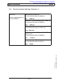
SECTION 5:
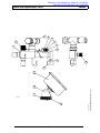
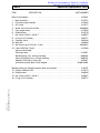
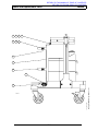
Spare and Replacement Parts List
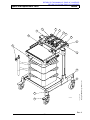
Fabius Trolley . . . . . . . . . . . . . . . . . . . . . . . . . . . . . . . . . . . . . . . . . . . . . . . . . . . . . . . . . 5-2, 5-3
Pin Index Trolley Assembly . . . . . . . . . . . . . . . . . . . . . . . . . . . . . . . . . . . . . . . . . . . . . . . 5-4, 5-5
Writing Tray . . . . . . . . . . . . . . . . . . . . . . . . . . . . . . . . . . . . . . . . . . . . . . . . . . . . . . . . . . . 5-6, 5-7
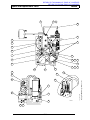
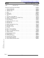
Gasbox, including vapor mounts . . . . . . . . . . . . . . . . . . . . . . . . . . . . . . . . . . . . . . . . . . . 5-8, 5-9
Flowmeter assembly . . . . . . . . . . . . . . . . . . . . . . . . . . . . . . . . . . . . . . . . . . . . . . . . . . 5-10, 5-11
Gas inlet assemblies . . . . . . . . . . . . . . . . . . . . . . . . . . . . . . . . . . . . . . . . . . . . . . . 5-12 thru 5-15
Circle 9 System: Support . . . . . . . . . . . . . . . . . . . . . . . . . . . . . . . . . . . . . . . . . . . . . . 5-16, 5-17
ii
Rev. A
RETURN TO THIS MANUAL'S TABLE OF CONTENTS
RETURN TO CD-ROM TABLE OF CONTENTS
Fabius®
Contents (continued)
DESCRIPTION
PAGE
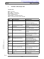
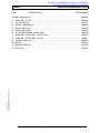
Circle 9 System: Inspiratory valve . . . . . . . . . . . . . . . . . . . . . . . . . . . . . . . . . . . . . . . . 5-18, 5-19
Circle 9 System: Expiratory valve . . . . . . . . . . . . . . . . . . . . . . . . . . . . . . . . . . . . . . . . 5-20, 5-21
Circle 9 System: Absorber . . . . . . . . . . . . . . . . . . . . . . . . . . . . . . . . . . . . . . . . . . . . . 5-22, 5-23
Circle 9 System: Intermediate piece . . . . . . . . . . . . . . . . . . . . . . . . . . . . . . . . . . . . . . 5-24, 5-25
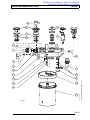
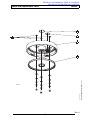
COSY Compact Breathing System . . . . . . . . . . . . . . . . . . . . . . . . . . . . . . . . . . . . . . . 5-26, 5-27
COSY Absorber Top . . . . . . . . . . . . . . . . . . . . . . . . . . . . . . . . . . . . . . . . . . . . . . . . . . 5-28, 5-29
COSY Absorber Canister . . . . . . . . . . . . . . . . . . . . . . . . . . . . . . . . . . . . . . . . . . . . . . 5-30, 5-31
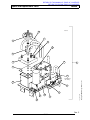
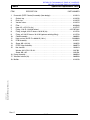
Control Box, Front Bezel Assembly, Fuse Data . . . . . . . . . . . . . . . . . . . . . . . . . . . . . 5-32, 5-33
Ventilator Assembly. . . . . . . . . . . . . . . . . . . . . . . . . . . . . . . . . . . . . . . . . . . . . . . . . . . 5-34, 5-35
Battery Assembly . . . . . . . . . . . . . . . . . . . . . . . . . . . . . . . . . . . . . . . . . . . . . . . . . . . . 5-36, 5-37
Pneumatic Control System (early design . . . . . . . . . . . . . . . . . . . . . . . . . . . . . . . . . . 5-38, 5-39
Pneumatic Control System (later design) . . . . . . . . . . . . . . . . . . . . . . . . . . . . . . . 5-39A, 5-39B
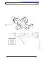
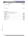
A-cone Switch, Fresh Gas Hose, Power Cord Assemblies . . . . . . . . . . . . . . . . . . . . . 5-40, 5-41
Flow sensor, O2 Sensor, Pressure Sensor Hose . . . . . . . . . . . . . . . . . . . . . . . . . . . . 5-42, 5-43
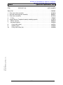
Optional Items:
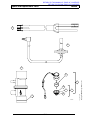
Bain Circuit Adapter, Breathing Pressure Gauge . . . . . . . . . . . . . . . . . . . . . . . . . . . . 5-44, 5-45
Cylinder Conversion Kit. . . . . . . . . . . . . . . . . . . . . . . . . . . . . . . . . . . . . . . . . . . . . . . . 5-46, 5-47
Semi-Open Adapter Assembly . . . . . . . . . . . . . . . . . . . . . . . . . . . . . . . . . . . . . . . . . . 5-48, 5-49
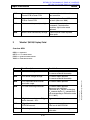
SECTION 6:
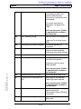
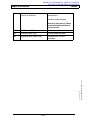
Fault-Cause-Remedy . . . . . . . . . . . . . . . . . . . . . . . . . . . . . . . . . . . . . . . . . . . . . . . . . . . . . . . . 6-1
SECTION 7:
Changes. . . . . . . . . . . . . . . . . . . . . . . . . . . . . . . . . . . . . . . . . . . . . . . . . . . . . . . . . . . . . . . . . . 7-1
SECTION 8:
Technical Memos . . . . . . . . . . . . . . . . . . . . . . . . . . . . . . . . . . . . . . . . . . . . . . . . . . . . . . . . . . . 8-1
Rev. C
iii
RETURN TO THIS MANUAL'S TABLE OF CONTENTS
RETURN TO CD-ROM TABLE OF CONTENTS
RETURN TO THIS MANUAL'S TABLE OF CONTENTS
RETURN TO CD-ROM TABLE OF CONTENTS
Fabius®
Introduction
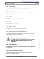
1.0 Introduction
Recommendations
Because of the sophisticated nature of North American Dräger. anesthesia equipment
and its critical importance in the operating room setting, it is highly recommended that
only appropriately trained and experienced professionals be permitted to service and
maintain this equipment. Please contact DrägerService® at (800) 543-5047 for service
of this equipment in North America. For service in Europe call 49 (451) 882-3781. For
service in other countries call (215) 721-5402.
North American Dräger recommends that the Fabius be serviced at six month
intervals. Periodic Manufacturer’s Certification agreements are available for
equipment manufactured by North American Dräger. Please contact us for further
information concerning these agreements.
North American Dräger. products /material in need of factory repair shall be sent to:
For North America and other
countries except Europe:
For service in Europe:
DrägerService®
Dräger Medizintechnik GmbH
Moislinger Allee 53-55
23542 Lübeck
Reparaturannahme
Germany
3124 Commerce Drive
Telford, PA 18969 U.S.A.
(Include RMA Number)
Guidelines
Troubleshooting the Fabius should always begin by communicating with those who
observed or experienced a problem with the unit.
Copyright 2000 Draeger Medical, Inc.
sec1_intro.fm
After performing any repair, replacement, calibration or adjustment, operation of the
unit must be verified, accompanied by a Test Certificate.
Copyright
Copyright© 2000 by Draeger Medical, Inc. All rights reserved. No part of this
publication may be reproduced, transmitted, transcribed, or stored in a retrieval
system in any form or by any means, electronic or mechanical, including
photocopying and recording, without written permission of Draeger Medical, Inc.
Disclaimer
The content of this manual is furnished for informational use only and is subject to
change without notice. Draeger Medical, Inc. assumes no responsibility or liability for
any errors or inaccuracies that may appear in this manual.
1-1
RETURN TO THIS MANUAL'S TABLE OF CONTENTS
RETURN TO CD-ROM TABLE OF CONTENTS
RETURN TO THIS MANUAL'S TABLE OF CONTENTS
RETURN TO CD-ROM TABLE OF CONTENTS
Fabius®
Function Description
2.0 Function Description
1
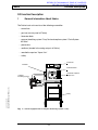
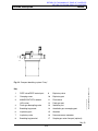
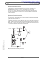
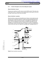
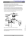
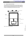
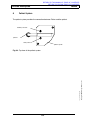
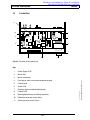
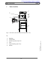
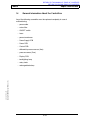
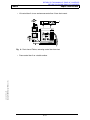
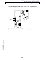
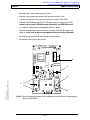
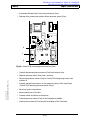
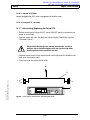
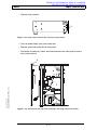
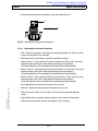
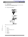
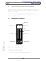
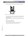
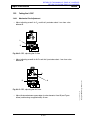
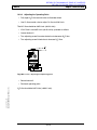
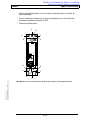
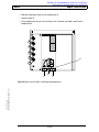
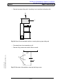
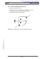
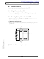
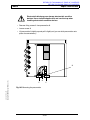
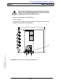
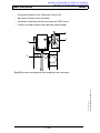
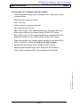
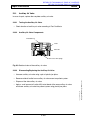
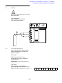
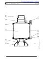
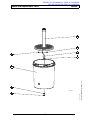
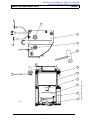
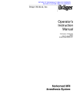
General Information About Fabius
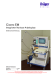
The Fabius basic unit consists of the following assemblies:
− control box
− gas box (on rear panel of Fabius)
− flowmeter block
− compact breathing system "Cosy"/circle absorption system "Circle System
9/Fabius"
− pneumatics
− ventilator (located in the swing-out part of Fabius)
− anesthetic vaporizer "Vapor 19.n"
− trolley
control box
ventilator
O2 +
flowmeter block
S-ORC
anesthetic vaporizer
"Vapor 19.n“
compact
breathing system
Copyright 2000 Draeger Medical, Inc.
sec2_funcdescrip_b.fm
Fabius
trolley
Fig. 1: Fabius equipped with a compact breathing system "Cosy"
2-1
Function Description
RETURN TO THIS MANUAL'S TABLE OF CONTENTS
RETURN TO CD-ROM TABLE OF CONTENTS
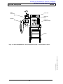
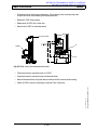
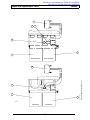
®
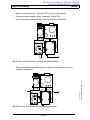
Fabius
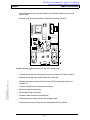
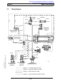
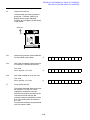
circle
absorption
control box
flowmeter
block
O2 +
S-ORC
ventilator
anesthetic
vaporizer "Vapor
max. 134 C
10
50
5
30
70
Fabius
trolley
2-2
Copyright 2000 Draeger Medical, Inc.
sec2_funcdescrip_b.fm
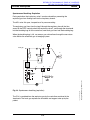
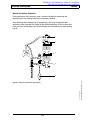
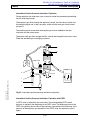
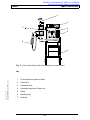
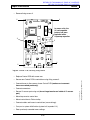
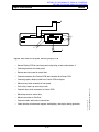
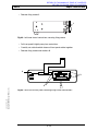
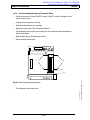
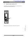
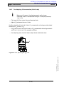
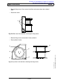
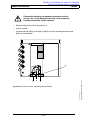
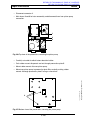
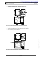
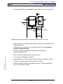
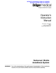
Fig. 2: Fabius equipped with a circle absorption system "Circle System 9 Fabius"
RETURN TO THIS MANUAL'S TABLE OF CONTENTS
RETURN TO CD-ROM TABLE OF CONTENTS
Fabius®
Function Description
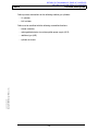
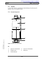
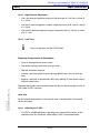
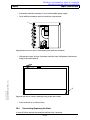
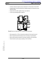
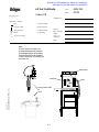
Fabius provides connections for the following medical gas cylinders:
− O2 cylinder
− N2O cylinder
Fabius can be retrofitted with the following assemblies/functions:
− drawer assembly
− rechargeable batteries for uninterruptible power supply (UPS)
− additional gas (AIR)
Copyright 2000 Draeger Medical, Inc.
sec2_funcdescrip_b.fm
− cylinder set mount
2-3
RETURN TO THIS MANUAL'S TABLE OF CONTENTS
RETURN TO CD-ROM TABLE OF CONTENTS
®
Fabius
Function Description
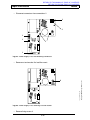
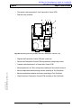
2
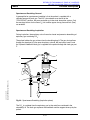
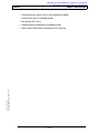
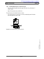
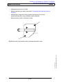
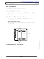
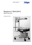
Fabius Function Diagrams
fresh-gas
decoupling
fresh gas
Paw
inspiratory
valve
O2
auxiliary air
lung
safety valve
breathing
ventilator
absorber
expiratory valve
PEEP control valve
.
V
APL valve
SPONT/ IPPV
electronic PEEP
valve
piston pump
outlet
sec2_funcdescrip_b.fm
Fig. 3: Function diagram of Fabius with compact breathing system "Cosy"
2-4
Copyright 2000 Draeger Medical, Inc.
MAN
RETURN TO THIS MANUAL'S TABLE OF CONTENTS
RETURN TO CD-ROM TABLE OF CONTENTS
Fabius®
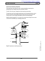
Function Description
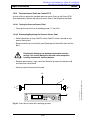
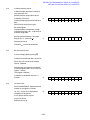
inspiratory valve
ventilator
fresh-gas
decoupling valve
Paw
O2
lung
fresh gas
2nd absorber (optional)
expiratory valve
and PEEP valve
1st absorber
flow
APL valve
SPONT/
IPPV
Copyright 2000 Draeger Medical, Inc.
sec2_funcdescrip_b.fm
breathing
bag
electronic
PEEP valve
MAN
piston pump
outlet
Fig. 4: Function diagram of Fabius with circle absorption system "Circle System 9
Fabius"
2-5
Function Description
2.1
RETURN TO THIS MANUAL'S TABLE OF CONTENTS
RETURN TO CD-ROM TABLE OF CONTENTS
®
Fabius
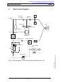
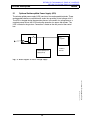
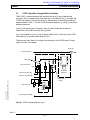
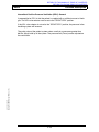
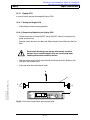
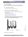
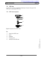
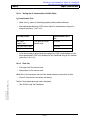
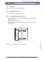
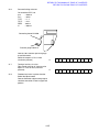
Optional Uninterruptible Power Supply (UPS)
The uninterruptible power supply (UPS) consists of two rechargeable batteries. These
rechargeable batteries are connected in series thus providing a total voltage of 24 V.
The UPS is charged during the operation phases. In the event of a voltage drop or a
complete power failure, the UPS can backup operation for approx. 90 minutes. The
UPS is located in the gas box. Connection is made on the rear panel of the control
box.
control box
5V
regulator
uninteruptible power
supply (UPS)
ventilator
monitor
2-6
Copyright 2000 Draeger Medical, Inc.
sec2_funcdescrip_b.fm
Fig. 5: Block diagram of Fabius’ voltage supply
RETURN TO THIS MANUAL'S TABLE OF CONTENTS
RETURN TO CD-ROM TABLE OF CONTENTS
Fabius®
Function Description
3
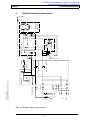
Function Diagram (2-gas version)
anesthetic
vaporizer
fresh gas
DUMMY TEXT
DUMMY TEXT
DUMMY TEXT
DUMMY TEXT
DUMMY TEXT
DUMMY TEXT
DUMMY TEXT
DUMMY TEXT
DUMMY TEXT
DUMMY TEXT
DUMMY TEXT
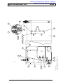
flowmeters
DUMMY TEXT
S-ORC
DUMMY TEXT
DUMMY TEXT
DUMMY TEXT
flow control valve
O2 flush
DUMMY TEXT
2-7
non-return valves
filter
N2O
O2
N2O
O2
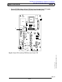
Fig. 6: Function Diagram (2-gas version)
filter
pressure
gauges
filter
filter
suction ejector
reservoir
pressure regulator
pressure regulator
inlet valve, vent
injector
RV1
gas box
Copyright 2000 Draeger Medical, Inc.
sec2_funcdescrip_b.fm
whistle
flowmeter block
DUMMY TEXT
RETURN TO THIS MANUAL'S TABLE OF CONTENTS
RETURN TO CD-ROM TABLE OF CONTENTS
®
Fabius
Function Description
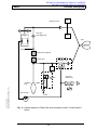
Function Diagram (3-gas version)
fresh gas
DUMMY TEXT
DUMMY TEXT
DUMMY TEXT
DUMMY TEXT
DUMMY TEXT
DUMMY TEXT
DUMMY TEXT
DUMMY TEXT
anesthetic
vaporizer
DUMMY TEXT
DUMMY TEXT
DUMMY TEXT
DUMMY TEXT
DUMMY TEXT
DUMMY TEXT
DUMMY TEXT
DUMMY TEXT
O2 flush
DUMMY TEXT
DUMMY TEXT
N2O
AIR
N2O
O2
2-8
Copyright 2000 Draeger Medical, Inc.
non-return valves
pressure
gauges
filter
filter
suction ejector
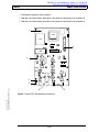
Fig. 7: Function Diagram of the Fabius (3-gas version)
sec2_funcdescrip_b.fm
pressure regulators
2 barr
1.5 barr
3 barr
inlet valve, vent
reservoir
RV1
gas box
S-ORC
flow control valve
injector
whistle
flowmeter block
flowmeters
O2
4
RETURN TO THIS MANUAL'S TABLE OF CONTENTS
RETURN TO CD-ROM TABLE OF CONTENTS
Fabius®
Function Description
5
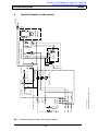
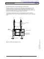
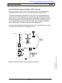
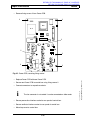
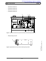
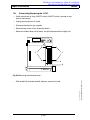
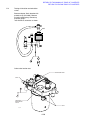
Function Description of the Gas Box
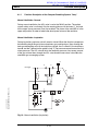
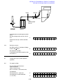
The supply gases flow through the built-in filters of the compressed-gas connections
and are then available at the pressure gauges. The pressure gauges indicate the
current pressure of the supply gases. The non-return valves prevent a reverse flow.
The pressure of the supply gases is reduced by pressure regulators. The
low-pressure supply gases then flow to the flowmeter block. As soon as the O2 supply
gas has reached a sufficient pressure, it flows through the spring-loaded non-return
valve RV 1 and fills the reservoir.
If the O2 supply fails or if the pressure of the O2 supply gas decreases below a certain
value, the 2-way valve switches over. The gas stored in the reservoir flows through the
2-way valve and the injector and activates the whistle (audible O2-failure alarm).
2-way valve
gas box
whistle
RV1
injector
reservoir
O2 flush
to the
anesthetic
vaporizer
suction ejector
to the flowmeter
filter
to the flowmeter
filter
to the flowmeter
O2
N2O
pressure
gauges
filter
supply gases
Copyright 2000 Draeger Medical, Inc.
sec2_funcdescrip_b.fm
pressure regulators
O2
AIR
N2O
non-return valves
Fig. 8: Function diagram of the gas box (3-gas version), part 1
2-9
Function Description
RETURN TO THIS MANUAL'S TABLE OF CONTENTS
RETURN TO CD-ROM TABLE OF CONTENTS
®
Fabius
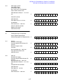
If the O2-flush button is pressed, the fresh-gas ejector prevents the fresh gas from
flowing back into the anesthetic vaporizer. This avoids an increase in the anesthetic
gas concentration.
fresh-gas
fresh gas
O2 flush
anesthetic
vaporizer
2-10
Copyright 2000 Draeger Medical, Inc.
sec2_funcdescrip_b.fm
Fig. 9: Function diagram of the gas box (3-gas version), part 2
RETURN TO THIS MANUAL'S TABLE OF CONTENTS
RETURN TO CD-ROM TABLE OF CONTENTS
Fabius®
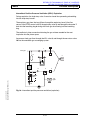
5.1
Function Description
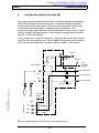
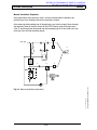
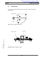
S-ORC (Sensitive Oxygen Ratio Controller)
The S-ORC is a control element that functions like an N2O shut-off device and
ensures a vital O2 concentration in the fresh gas. In the event of an O2 shortage, the
S-ORC limits the N2O flow such that the O2 concentration in the fresh gas does not
decrease below 21 vol.%. For the S-ORC to function properly O2 and N2O must have
different pressures.
If the O2 flow control valve is closed or if the O2 flow is lower than or equal to
200 mL/min, the S-ORC interrupts the N2O flow.
N2O can be added as of an O2 flow of approx. 300 mL/min. In this case, the S-ORC
also prevents O2 concentrations below 21 vol.%.
The inlet valve vent allows O2 to bypass the restrictor in the S-ORC when O2 flows
above 10 L/min. are needed.
fresh gas
from the O2 flush
flowmeter block
flowmeters
flow control valve
anesthetic
vaporizer
from the gas box (O2)
safety valve
(<1 bar)
Copyright 2000 Draeger Medical, Inc.
sec2_funcdescrip_b.fm
from the gas box (AIR)
inlet valve, vent
S-ORC
from the gas box (N2O)
Fig. 10: S-ORC function diagram, part 1
Rev. A
2-11
RETURN TO THIS MANUAL'S TABLE OF CONTENTS
RETURN TO CD-ROM TABLE OF CONTENTS
®
Fabius
Function Description
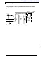
The flow control valves are used to adjust the O2 and N2O flows.
Restrictors located at the outlets of the S-ORC generate back-pressures. These
back-pressures exert a force on the control diaphragms of the S-ORC. The O2
back-pressure opens the S-ORC. The N2O back-pressure closes the S-ORC. The
pressure ratio at the control diaphragm affects the N2O flow.
The restrictors and the spring tension are dimensioned such that a minimum
concentration of 21 vol.% O2 is always ensured. The maximum O2 flow is approx. 9
L/min.
O2
N2O
flowmeters
restrictors
control
diaphragms
N2O check valve
operating-point
adjusting screw
O2
N2O
sec2_funcdescrip_b.fm
Fig. 11: S-ORC function diagram, part 2
2-12
Copyright 2000 Draeger Medical, Inc.
flow control
RETURN TO THIS MANUAL'S TABLE OF CONTENTS
RETURN TO CD-ROM TABLE OF CONTENTS
Fabius®
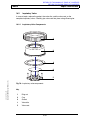
6
Function Description
Compact Breathing System "Cosy" /
Circle Absorption System "Circle System 9 Fabius"
Fabius is either equipped with a compact breathing system "Cosy" or with a circle
absorption system "Circle System 9 Fabius". They have the same function.
6.1
Compact Breathing System "Cosy"
The compact breathing system "Cosy" allows three modes of patient ventilation:
manual ventilation, spontaneous breathing, intermittent positive pressure ventilation
(IPPV). The APL valve (adjustable pressure limiting valve) has a selector which can
be used to toggle between "MAN" and "IPPV/SPONT".
In the "MAN" position, the compact breathing system is closed to atmosphere. This
position is the default position for manual ventilation of the patient. The APL valve
opening pressure can be adjusted from 5 to 70 hPa (mbar).
In the "IPPV/SPONT" position the APL valve is open to atmosphere. This position is
the default position for intermittent positive pressure ventilation and spontaneous
breathing.
Copyright 2000 Draeger Medical, Inc.
sec2_funcdescrip_b.fm
The pressure limit (Pmax) can also be adjusted during IPPV from 20 hPa (mbar) to
70 hPa (mbar) using the control box.
2-13
Function Description
RETURN TO THIS MANUAL'S TABLE OF CONTENTS
RETURN TO CD-ROM TABLE OF CONTENTS
®
Fabius
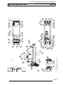
Key
PEEP valve/PEEP control port
9
Expiratory valve
2
Clamping screw
10
Expiratory port
3
MAN/SPONT-IPPV selector
11
Flow sensor
(APL valve)
12
Fresh-gas port
4
Fresh-gas decoupling valve
13
Ventilator port
5
Breathing bag mount
14
Anesthetic gas scavenging port
6
Inspiratory port
15
Absorber
7
Inspiratory valve
16
Pressure sensor connector
8
Breathing bag terminal
17
Sample-gas return line port (optional)
sec2_funcdescrip_b.fm
1
Rev. B
2-14
Copyright 2000 Draeger Medical, Inc.
Fig. 12: Compact breathing system "Cosy"
RETURN TO THIS MANUAL'S TABLE OF CONTENTS
RETURN TO CD-ROM TABLE OF CONTENTS
Fabius®
6.1.1
Function Description
Function Description of the Compact Breathing System "Cosy"
Manual Ventilation: General
During manual ventilation, the APL valve is set to the "MAN" position. The patient
system safety valve is activated. Only the warnings/alarms for the lower O2 limit and
for the upper airway pressure (Paw) are enabled. The piston of the ventilator is in the
upper end position in order to reduce the dead space volume of the ventilator.
Manual Ventilation: Inspiration
During inspiration, expiratory valve 1 remains closed. When the clinician compresses
the breathing bag 2 the gas mixture (expiratory gas and fresh gas) flows through the
fresh-gas decoupling valve 3, the inspiratory valve 4, the O2 sensor 5, the inspiratory
hose 6, and the Y-piece into the patient’s lung 7. The pressure sensor 8 measures the
airway pressure. The APL valve 9 limits the ventilation pressure. Any excess amount
of the gas mixture flows through the APL valve 9 and the non-return valve 10 to the
anesthetic gas scavenging system.
8
4
3
fresh gas
5
Copyright 2000 Draeger Medical, Inc.
sec2_funcdescrip_b.fm
2
1
9
MAN
10
Fig. 13: Manual ventilation (inspiration)
2-15
6
7
RETURN TO THIS MANUAL'S TABLE OF CONTENTS
RETURN TO CD-ROM TABLE OF CONTENTS
®
Fabius
Function Description
Manual Ventilation: Expiration
During expiration, the inspiratory valve 1 remains closed and thus prevents the
expiratory gas from flowing back into the inspiratory branch.
After releasing the breathing bag 2, the expiratory gas from the lung 3 flows through
the expiratory hose 4, the flow sensor 5, the PEEP control valve 6, the expiratory
valve 7, and through the absorber 8 into the breathing bag 2. At the same time, new
fresh gas flows into the breathing bag 2.
1
fresh gas
2
3
8
4
7
6
5
sec2_funcdescrip_b.fm
Fig. 14: Manual ventilation (expiration)
2-16
Copyright 2000 Draeger Medical, Inc.
MAN
RETURN TO THIS MANUAL'S TABLE OF CONTENTS
RETURN TO CD-ROM TABLE OF CONTENTS
Fabius®
Function Description
Spontaneous Breathing: General
A prerequisite for spontaneous breathing is that the patient is supplied with a
sufficient amount of fresh gas. The APL valve selector must be set to the
"SPONT/IPPV" position. No pressure builds up in the compact breathing system.
Only the warnings/alarms for the lower O2 limit and for the upper airway pressure
(Paw) are enabled.
Spontaneous Breathing: Inspiration
During inspiration, the expiratory valve 1 remains closed thus preventing rebreathing
of expiratory gas containing CO2.
The patient inhales the gas mixture (expiratory gas and fresh gas) from the breathing
bag 2. The gas mixture flows through the fresh-gas decoupling valve 3, the inspiratory
valve 4, the O2 sensor 5, the inspiratory hose 6, and through the Y-piece into the lung
7. The pressure sensor 8 measures the airway pressure.
8
3
4
fresh gas
5
2
Copyright 2000 Draeger Medical, Inc.
sec2_funcdescrip_b.fm
1
SPONT/
IPPV
Fig. 15: Spontaneous breathing (inspiration)
2-17
6
7
RETURN TO THIS MANUAL'S TABLE OF CONTENTS
RETURN TO CD-ROM TABLE OF CONTENTS
®
Fabius
Function Description
Spontaneous Breathing: Expiration
During expiration, the inspiratory valve 1 remains closed thus preventing the
expiratory gas from flowing back into the inspiratory branch.
The APL valve 2 is open, irrespective of its pressure setting.
The expiratory gas flows from the lung 3 through the expiratory hose 4, the flow
sensor 5, the PEEP control valve 6, the expiratory valve 7, and through the absorber 8
into the breathing bag 9. At the same time, new fresh gas flows into the breathing bag.
When the breathing bag is full, any excess gas mixture flows through the non-return
valve 10 into the anesthetic gas scavenging system.
1
fresh gas
9
3
4
8
7
6
5
2
Fig. 16: Spontaneous breathing (expiration)
The CO2 is scrubbed from the expiratory gas by the soda lime contained in the
absorber 8. The fresh gas replaces the anesthetic and oxygen taken up by the
patient.
2-18
sec2_funcdescrip_b.fm
10
Copyright 2000 Draeger Medical, Inc.
SPONT/
IPPV
RETURN TO THIS MANUAL'S TABLE OF CONTENTS
RETURN TO CD-ROM TABLE OF CONTENTS
Fabius®
Function Description
Intermittent Positive Pressure Ventilation (IPPV): General
A prerequisite for IPPV is that the patient is supplied with a sufficient amount of fresh
gas. The APL valve selector must be set to the "SPONT/IPPV" position.
If the APL valve selector is not set to the "SPONT/IPPV" position, the pressure in the
breathing system will increase.
Copyright 2000 Draeger Medical, Inc.
sec2_funcdescrip_b.fm
The safety valve of the patient system makes sure that no pressures greater than
80 hPa (mbar) build up in the system. The pressure limit (Pmax) can be adjusted on
the control box.
2-19
RETURN TO THIS MANUAL'S TABLE OF CONTENTS
RETURN TO CD-ROM TABLE OF CONTENTS
®
Fabius
Function Description
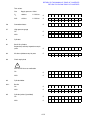
Intermittent Positive Pressure Ventilation (IPPV): Inspiration
During inspiration, the PEEP control valve 1 remains closed. The control pressure
present at the PEEP control valve 1 varies with the set pressure limit (Pmax).
The pressure generated by the ventilator’s piston closes the fresh-gas decoupling
valve 2. The gas mixture (expiratory gas and fresh gas) flows through the inspiratory
valve 3, the O2 sensor 4, the inspiratory hose 5, and through the Y-piece into the lung
6. The pressure sensor 7 measures the airway pressure. The ventilation pressure
cannot exceed the pressure limit (Pmax) set on the control box because the PEEP
control valve 1 opens. The fresh gas then fills the breathing bag 8.
Any excess fresh gas flows through the open APL valve 9, and through the non-return
valve 10 into the anesthetic gas scavenging system.
7
2
3
fresh gas
4
8
5
6
1
9
10
sec2_funcdescrip_b.fm
Fig. 17: Intermittent positive pressure ventilation (inspiration)
2-20
Copyright 2000 Draeger Medical, Inc.
SPONT/
IPPV
RETURN TO THIS MANUAL'S TABLE OF CONTENTS
RETURN TO CD-ROM TABLE OF CONTENTS
Fabius®
Function Description
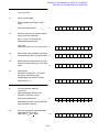
Intermittent Positive Pressure Ventilation (IPPV): Expiration
During expiration, the inspiratory valve 1 remains closed thus preventing rebreathing
into the inspiratory branch.
The expiratory gas from the lung 2 flows through the expiratory hose 3, the flow
sensor 4, the PEEP control valve 5, the expiratory valve 6, and through the absorber 7
back into the breathing bag 8 mixing with fresh gas also flowing into the breathing
bag.
The ventilator’s piston moves back drawing the gas mixture needed for the next
inspiration into the piston space.
Any excess fresh-gas flows through the APL valve 9, and through the non-return valve
10 into the anesthetic gas scavenging system.
1
fresh gas
8
2
3
7
6
5
4
9
Copyright 2000 Draeger Medical, Inc.
sec2_funcdescrip_b.fm
SPONT/
IPPV
10
Fig. 18: Intermittent positive pressure ventilation (expiration)
2-21
Function Description
6.1.2
RETURN TO THIS MANUAL'S TABLE OF CONTENTS
RETURN TO CD-ROM TABLE OF CONTENTS
®
Fabius
Cosy Absorber
The absorber is filled with fresh soda lime. The soda lime scrubs CO2 from the
respiratory gas and, because it is humidified, it prevents any absorption of
anesthetics.
2-22
Copyright 2000 Draeger Medical, Inc.
sec2_funcdescrip_b.fm
Expired soda lime changes its color. The soda lime must be replaced when two thirds
of the soda lime in a canister are discolored.
RETURN TO THIS MANUAL'S TABLE OF CONTENTS
RETURN TO CD-ROM TABLE OF CONTENTS
Fabius®
6.2
Function Description
Circle Absorption System "Circle System 9 Fabius"
The circle absorption system "Circle System 9 Fabius" allows three modes of patient
ventilation: manual ventilation, spontaneous breathing, intermittent positive pressure
ventilation (IPPV). The APL valve (adjustable pressure limiting valve) has a selector
which can be used to toggle between "MAN" and "IPPV/SPONT".
In the "MAN" position, the compact breathing system is closed to atmosphere. This
position is the default position for manual ventilation of the patient. The APL valve
opening pressure can be adjusted from 5 to 70 hPa (mbar).
In the "IPPV/SPONT" position the APL valve is open to atmosphere. This position is
the default position for intermittent positive pressure ventilation and spontaneous
breathing.
Copyright 2000 Draeger Medical, Inc.
sec2_funcdescrip_b.fm
The pressure limit (Pmax) can also be adjusted during IPPV from 20 hPa (mbar) to
70 hPa (mbar) using the control box.
2-23
RETURN TO THIS MANUAL'S TABLE OF CONTENTS
RETURN TO CD-ROM TABLE OF CONTENTS
®
Fabius
Function Description
1
18
2
17
3
16
4
5
15
14
13
6
12
11
7
10
9
8
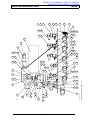
Fig. 19: Circle absorption system "Circle System 9 Fabius"
Inspiratory valve
10
Non-return valve
2
Pressure-measuring port (Paw)
11
APL valve
3
Fresh-gas decoupling valve
12
MAN/SPONT-IPPV selector
4
Fresh-gas port
13
Flow sensor
5
First absorber
14
Expiratory valve
6
Second absorber (optional)
15
PEEP valve
7
Clamping screw
16
Ventilator port
8
Breathing bag
17
Inspiratory port
9
Anesthetic gas scavenging port
18
O2 sensor
2-24
Copyright 2000 Draeger Medical, Inc.
1
sec2_funcdescrip_b.fm
Key
RETURN TO THIS MANUAL'S TABLE OF CONTENTS
RETURN TO CD-ROM TABLE OF CONTENTS
Fabius®
6.2.1
Function Description
Function Description of the Circle Absorption System
Manual Ventilation: General
During manual ventilation, the APL valve is set to the "MAN" position. The safety valve
of the patient system is activated. Only the warnings/alarms for the lower O2 limit and
the upper airway pressure limit (Paw) are enabled.
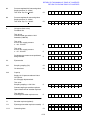
Manual Ventilation: Inspiration
When the clinician compresses the breathing bag 1, the gas mixture (expiratory and
fresh gas) flows through the absorber 2, the open fresh-gas decoupling valve 3, the
open inspiratory valve 4, the inspiratory hose 5, and through the Y-piece 6 into the
lung 7. The CO2 contained in the gas mixture is scrubbed by the soda lime in the
absorbers 2. The ventilation pressure is limited by the APL valve 8. The expiratory
valve 9 remains closed. Any excess amount of the gas mixture flows through the APL
valve 8, and the non-return valve 10 into the anesthetic gas scavenging system 11.
4
3
5
6
2
7
Copyright 2000 Draeger Medical, Inc.
sec2_funcdescrip_b.fm
8
9
10
1
11
Fig. 20: Manual ventilation (inspiration)
2-25
Function Description
RETURN TO THIS MANUAL'S TABLE OF CONTENTS
RETURN TO CD-ROM TABLE OF CONTENTS
®
Fabius
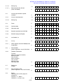
Manual Ventilation: Expiration
During expiration, the inspiratory valve 1 remains closed thus preventing the
expiratory gas from flowing back into the inspiratory branch.
After releasing the breathing bag 2, the expiratory gas flows through the open
expiratory valve 3 and the flow sensor 4 into the breathing bag 2. At the same time,
fresh gas from the fresh-gas port 5 flows through the absorber(s) into the breathing
bag 2.
1
5
3
4
sec2_funcdescrip_b.fm
Fig. 21: Manual ventilation (expiration)
2-26
Copyright 2000 Draeger Medical, Inc.
2
RETURN TO THIS MANUAL'S TABLE OF CONTENTS
RETURN TO CD-ROM TABLE OF CONTENTS
Fabius®
Function Description
Spontaneous Breathing: General
A prerequisite for spontaneous breathing is that the patient is supplied with a
sufficient amount of fresh gas. The APL valve selector must be set to the
"IPPV/SPONT" position. No pressure builds up in the circle absorption system. Only
the warnings/alarms for the lower O2 limit and the upper airway pressure limit (Paw)
are enabled.
Spontaneous Breathing: Inspiration
During inspiration, the expiratory valve 1 remains closed and prevents rebreathing of
expiratory gas containing CO2.
The patient inhales the gas mixture from the breathing bag 2. The gas mixture flows
through the absorber(s) 3, the open inspiratory valve 4, the inspiratory hose 5, and
the Y-piece 6. Additional fresh gas is supplied to the patient through the fresh-gas port
7.
4
5
7
6
Copyright 2000 Draeger Medical, Inc.
sec2_funcdescrip_b.fm
3
1
2
Fig. 22: Spontaneous Breathing (inspiration phase)
The CO2 is scrubbed from the expiratory gas by the soda lime contained in the
absorber(s) 3. The fresh gas replaces the anesthetic and the oxygen taken up by the
patient.
2-27
Function Description
RETURN TO THIS MANUAL'S TABLE OF CONTENTS
RETURN TO CD-ROM TABLE OF CONTENTS
®
Fabius
Spontaneous Breathing: Expiration
During expiration, the inspiratory valve 1 remains closed thus preventing the
expiratory gas from flowing back into the inspiratory branch.
The APL valve 2 is open, irrespective of the current pressure setting.
The expiratory gas flows through the expiratory hose 3, the open expiratory valve 4,
the flow sensor 5, into the breathing bag 6. At the same time, fresh gas from the
fresh-gas port 7 flows through the absorber(s) 8 into the breathing bag 6.
When the breathing bag 6 is full, any excess gas mixture flows through the non-return
valve 9 into the anesthetic gas scavenging system 10.
1
7
3
8
2
4
5
10
Fig. 23: Spontaneous breathing (expiration)
2-28
sec2_funcdescrip_b.fm
6
Copyright 2000 Draeger Medical, Inc.
9
RETURN TO THIS MANUAL'S TABLE OF CONTENTS
RETURN TO CD-ROM TABLE OF CONTENTS
Fabius®
Function Description
Intermittent Positive Pressure Ventilation (IPPV): General
A prerequisite for IPPV is that the patient is supplied with a sufficient amount of fresh
gas. The APL valve selector must be set to the "IPPV/SPONT" position.
If the APL valve selector is not set to the "IPPV/SPONT" position, the pressure in the
breathing system will increase.
Copyright 2000 Draeger Medical, Inc.
sec2_funcdescrip_b.fm
The safety valve of the patient system limits the pressure to 80 hPa (mbar). The
desired pressure limit (Pmax) can be adjusted on the control box.
2-29
Function Description
RETURN TO THIS MANUAL'S TABLE OF CONTENTS
RETURN TO CD-ROM TABLE OF CONTENTS
®
Fabius
Intermittent Positive Pressure Ventilation (IPPV): Inspiration
During inspiration, the inspiratory valve 1 remains open. The PEEP valve closes the
expiratory valve 2. A control pressure, which varies with the pressure limit (Pmax) set
on the control box, is applied to the PEEP valve.
The gas mixture (expiratory and fresh gas) from the ventilator 3 flows through the
hose 4, the inspiratory valve 1, the inspiratory hose 5, and through the Y-piece 6 into
the lung 7. The ventilation pressure cannot exceed the pressure limit (Pmax) set on
the control box. The fresh gas flows through the absorbers and fills the breathing bag.
Any excess amount of fresh gas flows through the APL valve 8 and the non-return
valve 9 into the anesthetic gas scavenging system 10.
1
5
fresh gas
6
PEEP valve
7
4
8
ventilator
2
10
3
If the inspiratory pressure exceeds the set pressure limit (Pmax), the PEEP valve
opens. Any excess gas flows through the PEEP valve, and the flow sensor into the
circle absorption system.
2-30
sec2_funcdescrip_b.fm
Fig. 24: Intermittent positive pressure ventilation (inspiration)
Copyright 2000 Draeger Medical, Inc.
9
RETURN TO THIS MANUAL'S TABLE OF CONTENTS
RETURN TO CD-ROM TABLE OF CONTENTS
Fabius®
Function Description
Intermittent Positive Pressure Ventilation: Expiration
During expiration, the inspiratory valve 1 remains closed thus preventing rebreathing
into the inspiratory branch.
The expiratory gas flows through the expiratory valve 2, the flow sensor 3, back into
the breathing bag 4 and, at the same time, mixes with the fresh-gas from the fresh
gas port 5.
The ventilator piston moves back drawing the gas mixture needed for the next
inspiration into the piston space.
The excess fresh gas flows through the APL valve 6, and through the non-return valve
7 into the anesthetic gas scavenging system 8.
1
5
PEEP valve
2
6
ventilator
3
Copyright 2000 Draeger Medical, Inc.
sec2_funcdescrip_b.fm
7
8
4
Fig. 25: Intermittent positive pressure ventilation (expiration)
Intermittent Positive Pressure Ventilation: Expiration with PEEP
A PEEP value is adjusted on the control box. The corresponding PEEP control
pressure is applied to the diaphragm of the PEEP valve. The diaphragm plate of the
PEEP valve pushes the mica disc of the expiratory valve which closes the crater. If the
pressure of the expiratory gas exceeds the set PEEP value, the expiratory valve 2
opens.
2-31
Function Description
6.2.2
RETURN TO THIS MANUAL'S TABLE OF CONTENTS
RETURN TO CD-ROM TABLE OF CONTENTS
®
Fabius
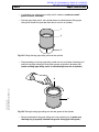
Absorber
The absorber is filled with fresh soda lime. The soda lime scrubs the CO2 from the
respiratory gas and, because it is humidified, it prevents any absorption of
anesthetics.
2-32
Copyright 2000 Draeger Medical, Inc.
sec2_funcdescrip_b.fm
Expired soda lime changes its color. The soda lime must be replaced when two thirds
of the soda lime in a canister are discolored.
RETURN TO THIS MANUAL'S TABLE OF CONTENTS
RETURN TO CD-ROM TABLE OF CONTENTS
Fabius®
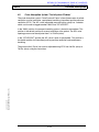
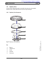
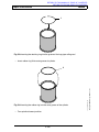
7
Function Description
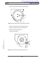
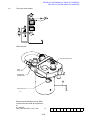
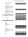
Ventilation Unit
The ventilation unit consists of the ventilator and the pneumatics.
The ventilation unit is powered with DC voltage from the control box or, in the event of
mains power failure, from the uninterruptible power supply (UPS). The ventilator
delivers the fresh gas (at a given volume, pressure, and frequency) which comes from
the flowmeter block and from the breathing bag to the patient. During expiration, the
bag-type rolling seal of the ventilator fills with the expiratory gas from the patient and
with the fresh gas stored in the breathing bag.
During inspiration, a specific amount of this gas mixture is delivered to the patient. A
safety valve limits the ventilation pressure.
If the fresh gas in the machine is not sufficient, the ventilator draws in ambient air
through the auxiliary air valve located in the patient system.
7.1
Ventilator
Copyright 2000 Draeger Medical, Inc.
sec2_funcdescrip_b.fm
The ventilator is mounted into the swivel-out compartment of Fabius. The cover of the
ventilator has a connection for the respiratory hose of the circle absorption system or
compact breathing system, respectively. The ventilator is powered electrically. Its
control system and keypad are located in/on the control box. The control box also
contains the basic monitoring system. A sight window on the swivel out compartment
allows the clinician to watch the movement of the rolling seals.
2-33
Function Description
7.1.1
RETURN TO THIS MANUAL'S TABLE OF CONTENTS
RETURN TO CD-ROM TABLE OF CONTENTS
®
Fabius
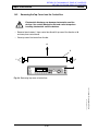
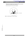
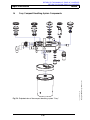
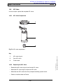
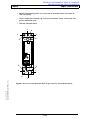
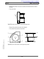
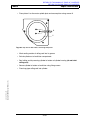
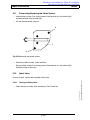
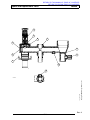
Function Principle of the Ventilator
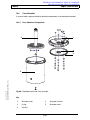
The ventilator consists of a piston and a cylinder. The recirculating ball screw driven
by the motor moves the piston. When the piston moves back it slides completely over
the motor. The incremental encoder determines the number of motor rotations and
transmits the corresponding signal to the microprocessor. The rolling seal is attached
to the piston. The bag-type rolling seal encloses the inspiratory volume.
patient system
cylinder
bag-type
rolling seal
rolling seal
piston
recirculating ball screw
motor
sec2_funcdescrip_b.fm
Fig. 26: Sectional view of the ventilator
2-34
Copyright 2000 Draeger Medical, Inc.
incremental encoder
RETURN TO THIS MANUAL'S TABLE OF CONTENTS
RETURN TO CD-ROM TABLE OF CONTENTS
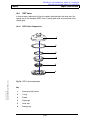
Fabius®
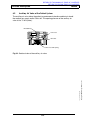
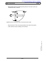
7.2
Function Description
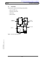
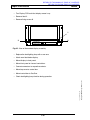
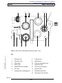
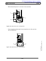
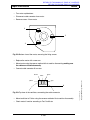
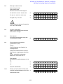
Pneumatics
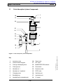
The pneumatics comprises the following subassemblies:
− electronic PEEP valve
− Pneumatic Control PCB
− piston pump
− pressure sensor
X5
X4
X6
X1
electronic
PEEP valve
X3
Pneumatic
Control PCB
X2
piston pump
pressure
Copyright 2000 Draeger Medical, Inc.
sec2_funcdescrip_b.fm
Fig. 27: Top view of the pneumatics
2-35
RETURN TO THIS MANUAL'S TABLE OF CONTENTS
RETURN TO CD-ROM TABLE OF CONTENTS
®
Fabius
Function Description
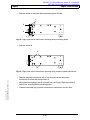
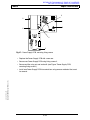
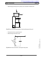
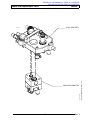
7.2.1
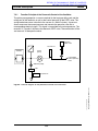
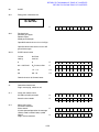
Function Principle of the Pneumatic Control of the Ventilator
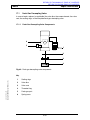
The piston pump generates a vacuum required for the bag-type rolling seal and the
rolling seal of the ventilator as well as the control pressure for the PEEP valve. The
spring-loaded non-return valve limits the vacuum to −200 hPa (mbar). A pressure
sensor measures the current pressure and converts the pressure value into a
corresponding electrical signal. This signal is transmitted to the microprocessor. The
reservoir V1 "smooths" the flow to the electronic PEEP valve. The combination of filter
and reservoir V2 dampen the noise.
pneumatics
electronic
PEEP valve
E
reservoir V1
P
ventilator
piston
pump
to the PEEP
valve/ expiratory
valve
–200 hPa (mbar)
filter
reservoir V2
2-36
Copyright 2000 Draeger Medical, Inc.
sec2_funcdescrip_b.fm
Fig. 28: Function diagram of the pneumatic control of the ventilator
RETURN TO THIS MANUAL'S TABLE OF CONTENTS
RETURN TO CD-ROM TABLE OF CONTENTS
Fabius®
Function Description
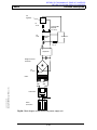
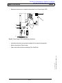
7.3
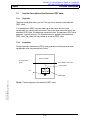
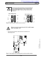
Function Description of the Electronic PEEP Valve
7.3.1
Expiration
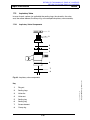
The piston pump generates a gas flow. This gas flow is directed to the electronic
PEEP valve.
If an endexpiratory PEEP value has been set on the control box, this value
corresponds to a specific electrical current. The current flows across the coil of the
electronic PEEP valve. The diaphragm closes the crater. The electronic PEEP valve
generates a control pressure. This control pressure is applied to the mechanical
PEEP valve. The patient can only exhale up to the set PEEP value.
7.3.2
Inspiration
During inspiration, the electronic PEEP valve generates a control pressure which
corresponds to the set pressure limit (Pmax).
electronic PEEP
flow from piston
pump
to the PEEP control valve
to atmosphere
coil
Copyright 2000 Draeger Medical, Inc.
sec2_funcdescrip_b.fm
diaphragm
Fig. 29: Function diagram of the electronic PEEP valve
2-37
Function Description
8
RETURN TO THIS MANUAL'S TABLE OF CONTENTS
RETURN TO CD-ROM TABLE OF CONTENTS
®
Fabius
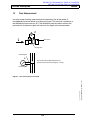
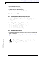
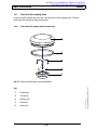
Patient System
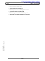
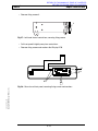
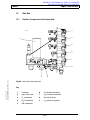
The patient system provides the connection between Fabius and the patient.
auxiliary-air valve
patient
safety valve
patient system
2-38
Copyright 2000 Draeger Medical, Inc.
sec2_funcdescrip_b.fm
Fig. 30: Top view of the patient system
RETURN TO THIS MANUAL'S TABLE OF CONTENTS
RETURN TO CD-ROM TABLE OF CONTENTS
Fabius®
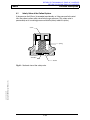
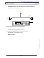
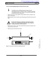
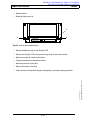
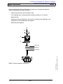
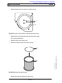
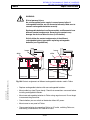
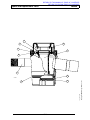
8.1
Function Description
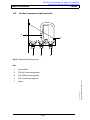
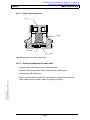
Safety Valve of the Patient System
If the pressure limit (Pmax) is exceeded considerably, or if the pressure limit control
fails, the patient system safety valve limits the gas pressure. This safety valve is
permanently set to a working pressure of 60 hPa (mbar) to 80 hPa (mbar).
screw
spring
valve disc
washer
Copyright 2000 Draeger Medical, Inc.
sec2_funcdescrip_b.fm
Fig. 31: Sectional view of the safety valve
2-39
Function Description
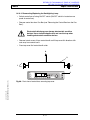
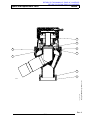
8.2
RETURN TO THIS MANUAL'S TABLE OF CONTENTS
RETURN TO CD-ROM TABLE OF CONTENTS
®
Fabius
Auxiliary Air Valve of the Patient System
The auxiliary air valve allows the patient to spontaneously breathe ambient air should
the medical gas supply and/or Fabius fail. The opening pressure of the auxiliary air
valve is 0 to –5 hPa (mbar).
threaded ring
valve seat
valve disc
valve cross with spring
2-40
Copyright 2000 Draeger Medical, Inc.
sec2_funcdescrip_b.fm
Fig. 32: Sectional view of the auxiliary air valve
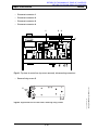
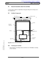
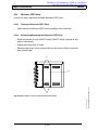
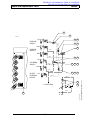
O2 sensor
EEPROM
O2 channel
P(t) channel
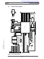
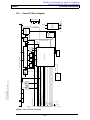
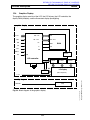
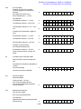
Fig. 33: Electronics block diagram
2-41
Discrete
peripherals
Motor
Encoder
Piston
Limit switch
Ventilator
Voltage
transformer
±12V
RAM
EPROM
Buzzer
Current
RAM
Microcontroller
Fan
Power PCB
Quadrature
encoder
5V
Pressure
sensor
Pneumatic
Control PCB
Pneumatics
0–0.6A
Electronic PEEP
valve
Piston
pump
Voltage supply
24V
Pump on/off
Voltage
transformer
Relay
EPROM
Peripherals
Power Supply PCB
110VAC/
220VAC
To mechanical PEEP valve
External battery
Transformer
Fabius®
Control
knob
Keys
LEDs
Graphics
display
Front Panel
5V voltage
monitoring
Microcontroller
2-min
silence
9
Paw
Flow sensor
Flow channel
Control PCB
Copyright 2000 Draeger Medical, Inc.
sec2_funcdescrip_b.fm
RETURN TO THIS MANUAL'S TABLE OF CONTENTS
RETURN TO CD-ROM TABLE OF CONTENTS
Function Description
Electronics Block Diagram
RETURN TO THIS MANUAL'S TABLE OF CONTENTS
RETURN TO CD-ROM TABLE OF CONTENTS
®
Fabius
Function Description
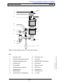
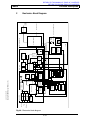
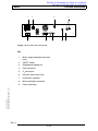
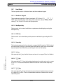
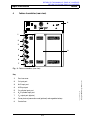
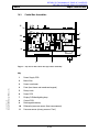
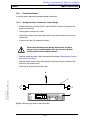
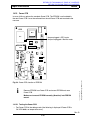
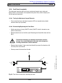
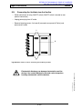
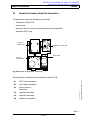
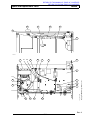
10
Control Box
11
10
1
9
2
8
3
4
7
6
5
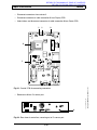
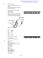
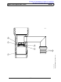
Fig. 34: Top view of the control box
Power Supply PCB
2
Mains filter
3
Mains transformer
4
Front panel (front frame and membrane keypad)
5
Control knob
6
Power PCB
7
Graphics display and backlighting lamp
8
Control PCB
9
Rechargeable battery or Goldcap capacitor
10
Differential pressure sensor (flow)
11
Airway pressure sensor (Paw)
2-42
Copyright 2000 Draeger Medical, Inc.
1
sec2_funcdescrip_b.fm
Key
RETURN TO THIS MANUAL'S TABLE OF CONTENTS
RETURN TO CD-ROM TABLE OF CONTENTS
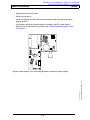
Fabius®
Function Description
2
1
4
3
1 AT
ON
OFF
1 AT
V-Sensor
Paw
8
1
9
15
9
8
7
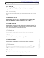
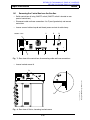
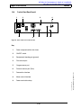
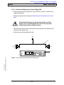
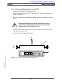
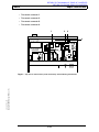
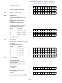
Fig. 35: Rear View of the Control Box
Key
1
Mains supply receptacle with mains
fuses
2
ON/OFF switch
3
Equipotential bonding pin
4
Flow sensor port
5
O2 sensor port
6
Pressure sensor port (Paw)
7
Pneumatics connector
8
Motor and Battery connector
9
Power cord clamp
Copyright 2000 Draeger Medical, Inc.
sec2_funcdescrip_b.fm
m
Interface C
Interface M
Rev. A
2-43
O2-Sensor
6
5
Function Description
10.1
RETURN TO THIS MANUAL'S TABLE OF CONTENTS
RETURN TO CD-ROM TABLE OF CONTENTS
®
Fabius
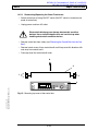
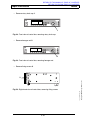
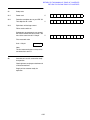
Power Supply Unit
The power supply unit consists of the Power Supply PCB, the mains supply
receptacle, the ON/OFF switch, the fuses, the mains filter, and the mains transformer.
The power supply unit powers Fabius with the following voltages:
− +24 VDC
− +5 VDC
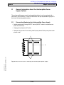
10.1.1
Power Supply PCB
The Power Supply PCB uses the voltage regulator L4960 to generate the +5 V
operating voltage.
Two voltage regulators LT1074 connected in parallel generate the supply voltage
(28 V) and the rechargeable battery charging voltage.
The resistor S1 (the conductor is designed as sense resistor) is used to measure the
charging current of the rechargeable battery. An integrated circuit transmits the signal
to the microcontroller.
The signals A and B are fed back to the 24 V voltage regulators and function as
charging current limitation.
2-44
Copyright 2000 Draeger Medical, Inc.
sec2_funcdescrip_b.fm
The Power Supply PCB monitors the rechargeable battery voltage, generates the
battery symbol control on the display and the power failure alarm.
RETURN TO THIS MANUAL'S TABLE OF CONTENTS
RETURN TO CD-ROM TABLE OF CONTENTS
Fabius®
Function Description
5V
regulator
F1
1.6 A
rechargeable
batteries
(2 x 12 V)
F4
4 AT
ON/OFF
switch
electronics
F5
2.5 A
2
step-down
bridge-connecte
d rectifier
F2
3.15 A
40 VAC
mains
Copyright 2000 Draeger Medical, Inc.
sec2_funcdescrip_b.fm
127
VAC
127
VAC
mains filter
mains
connection
Fig. 36: Block diagram of the control box power supply unit
2-45
Function Description
10.2
RETURN TO THIS MANUAL'S TABLE OF CONTENTS
RETURN TO CD-ROM TABLE OF CONTENTS
®
Fabius
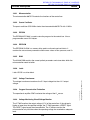
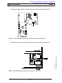
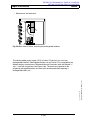
Control PCB
The Control PCB measures and monitors all measuring and status signals. If an error
occurs, the Control PCB switches off the solenoids, and activates the buzzer. The
Control PCB is then reset.
The Control PCB is equipped with the pressure sensors for the airway pressure (Paw)
and the flow (∆P).
The Control PCB comprises the following components:
− microcontroller
− quartz oscillator
− EPROM
− EEPROM
− RAM
− latch
− 9 V rechargeable battery or Goldcap capacitor
The Control PCB provides the following functions:
− measurement of oxygen concentration, flow, and pressure
− voltage monitoring and power-on
− LED control
− 2-min silence timer
− buzzer and buzzer control
− contrast control
− control knob scanning
− motor current monitoring
− membrane pressure
sec2_funcdescrip_b.fm
− charging voltage monitoring
− display control
− ±12 V generation
Rev. A
2-46
Copyright 2000 Draeger Medical, Inc.
− membrane keypad scanning
Fig. 37: Control PCB block diagram
2-47
To graphics display
From power supply
Data
Data
D7
9-V
rechargeable
Data
CS logics
Flip
Flop
Silence unit
512kx8
32kx8
(optional)
Latch
Timer
(2 min)
Address
EPROM
RAM
Bank2
Silence key
Silence LED
Buzzer (on/off)
Silence status
Bank1
Bank0
512kx8
To control knob
Power switch (STA)
Jumper
PSEN
EEPROM
O2
O2
LED drivers
VCC
To membrane keypad
Microcontroller
12MHz
Differential
pressure
sensor
Flow
Pressure
V+
V–
GNDA
TXD0
RXD0
VCC
Ventilation pressure
I/E
Voltage
transformer
(±12 V)
VCONTRAST
(approx.
–7 V)
VCC
Shutdown status (NETZ STS)
RESET
P MEMBRAN (analog)
NOT AUS (on/off)
MOTI (analog)
PUMP ON (on/off)
PEEP ON
V+
Voltage
monitoring and
power on
Paw
sensor
5V
Fabius®
Buzzer
Power switch (S2)
Power switch (S1)
POWERFAIL
BATT_NETZ
U BATT (charging voltage)
CS
A0
D6
D5
D4
D3
D2
D1
D0
Serial data
Control knob
VCONTRAST
O2 channel B (analog)
VCC
Serial clock
Quit
V+
Flow channel (analog)
V+
O2 channel A (analog)
Copyright 2000 Draeger Medical, Inc.
Key matrix
V–
Pressure
10.3
To Power PCB
sec2_funcdescrip_b.fm
RETURN TO THIS MANUAL'S TABLE OF CONTENTS
RETURN TO CD-ROM TABLE OF CONTENTS
Function Description
Control PCB Block Diagram
Function Description
10.3.1
RETURN TO THIS MANUAL'S TABLE OF CONTENTS
RETURN TO CD-ROM TABLE OF CONTENTS
®
Fabius
Microcontroller
The microcontroller 80C517A controls the functions of the control box.
10.3.2
Quartz Oscillator
The quartz oscillator QOS12Mhz clocks the microcontroller 80C517A with 12 MHz.
10.3.3
EPROM
The EPROM M27C4001 is used to store the program for the control box. It has a
programmable area of 512 kbytes.
10.3.4
EEPROM
The EEPROM X24C04 is a memory chip used to write and read serial data. It
contains the set customer parameters and the zero values of flow, pressure, and O2.
10.3.5
RAM
The 32 Kx8 RAM contains the current patient parameters and stores data which the
microcontroller needs to buffer.
10.3.6
Latch
Latch HC373 is a driver block.
Voltage Transformer
The voltage transformer transforms the 5 V input voltage into the ±12 V output
voltage.
Oxygen Concentration Evaluation
The operational amplifier OP07 evaluates the voltage of the O2 sensor.
10.3.9
Voltage Monitoring Circuit/Voltage Monitor
The IC 7665 monitors the output voltage (+5 V) of the control box. If the voltage is
higher or lower than the specified voltage, the IC 7665 generates a RESET signal.
This RESET signal resets the microcontroller. The IC makes sure that the
microcontroller only initializes when the operating voltage has reached an adequate
level.
2-48
sec2_funcdescrip_b.fm
10.3.8
Copyright 2000 Draeger Medical, Inc.
10.3.7
RETURN TO THIS MANUAL'S TABLE OF CONTENTS
RETURN TO CD-ROM TABLE OF CONTENTS
Fabius®
Function Description
10.3.10 LED Control
The LEDs (LED_MAN, LED_IPV, LED_SBY, LED_SIL, LED_WAR and LED_ALA) are
triggered by the transistors BCX17.
10.3.11 2-Min Silence Timer
The 2-min silence timer has a timer IC (74HC4060). The timer IC enables
suppression of the audible alarm for two minutes.
10.3.12 Buzzer and Buzzer Control
During operation, the buzzer is powered with 24 V. If a power failure occurs, the
built-in 9 V rechargeable battery on the Control PCB powers the buzzer. (Later
models have a Goldcap capacitor instead of a battery.) In the event of a failure, the
buzzer is triggered by the microcontroller.
10.3.13 Contrast Control
The operational amplifier TL072D generates the contrast voltage for the graphics
display. The contrast voltage is approximately –7 VDC to –8 VDC.
10.3.14 9V Rechargeable Battery or Goldcap Capacitor
In the event of a power failure, the 9 V rechargeable battery supplies the operating
voltage for the buzzer. The 24 V operating voltage supplies a charging circuit which
charges the rechargeable battery during normal operation.
Copyright 2000 Draeger Medical, Inc.
sec2_funcdescrip_b.fm
Later models have a Goldcap capacitor instead of a battery.
Rev. A
2-49
Function Description
10.4
RETURN TO THIS MANUAL'S TABLE OF CONTENTS
RETURN TO CD-ROM TABLE OF CONTENTS
®
Fabius
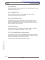
Power PCB
The Power PCB controls the piston pump, the electronic PEEP valve, the fan, the
ventilator motor, and the backlighting of the graphics display.
The Power PCB comprises the following components:
− microcontroller
− quartz oscillator
− EPROM
− latch
− MOSFET amplifier for the motor
− voltage transformer for the backlighting lamp
− PEEP valve control
− light barrier evaluation of the motor (limit switch)
− system temperature monitoring and fan control
− quadrature encoder
2-50
Copyright 2000 Draeger Medical, Inc.
sec2_funcdescrip_b.fm
− safety relay
Fig. 38: Power PCB block diagram
2-51
GNDD
VCC
TXD0
Quit
I: E
RXD0
RESET
Ventilation pressure (analog)
Shutdown status (NETZ_STA)
P MEMBRAN (analog)
NOT_AUS (on/off)
PEEP_AN (PWM 10 kHZ, 0...100%)
PUMP_ON (on/off)
Fan
VPP
FAN ON
Safety relay
Level
transf.
DIR 1
Level
transf
Level
transf.
FET power transistors
DIR 0
12 MHz
Microcontroller
PWR 1
MOTI (analog)
PUMP
PEEP
VCC
Level
transf.
PWR 0
VPP
MOT
To drive and pneumatic unit
TEMP
NTC
Motor
current
VCC
Addresses and data
To microcontroller (Control PCB)
Copyright 2000 Draeger Medical, Inc.
512kx8
EPROM
GNDD
VCC
VPP
GNDD
Voltage
transformer
To backlighting
Quadrature
encoder
Limit switch
VCC
10.5
GNDD
sec2_funcdescrip_b.fm
RETURN TO THIS MANUAL'S TABLE OF CONTENTS
RETURN TO CD-ROM TABLE OF CONTENTS
Fabius®
Function Description
Power PCB Block Diagram
To power supply
Function Description
10.5.1
RETURN TO THIS MANUAL'S TABLE OF CONTENTS
RETURN TO CD-ROM TABLE OF CONTENTS
®
Fabius
Microcontroller
The microcontroller 80C517A controls the functions of the Power PCB.
10.5.2
Quartz Oscillator
The quartz oscillator of the Control PCB clocks the microcontroller 80C517A with
12 MHz.
10.5.3
EPROM
The EPROM has a programmable area of 512 kbytes.
10.5.4
Latch
The latch HC373 is a driver block.
10.5.5
MOSFET Amplifier
The MOSFET amplifier controls the motor of the ventilator.
10.5.6
Voltage Transformer for the Backlighting Lamp
The voltage transformer E1241 transforms the input voltage into a corresponding
output voltage for the lamp of the backlighting.
10.5.7
PEEP Valve Control
The power field-effect transistor BUZ20 and the operational amplifier LM324 control
the PEEP valve.
10.5.8
Light Barrier Evaluation of the Motor
The IC 74HC14 evaluates the final position and the movement of the motor
(END-SCH, PHASE0, and PHASE1).
2-52
sec2_funcdescrip_b.fm
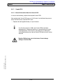
The voltage transformer will be damaged if used at no load. Do not
operate the voltage transformer without the lamp of the
backlighting.
Copyright 2000 Draeger Medical, Inc.
Risk of damage to the voltage transformer.
RETURN TO THIS MANUAL'S TABLE OF CONTENTS
RETURN TO CD-ROM TABLE OF CONTENTS
Fabius®
10.5.9
Function Description
System Temperature Monitoring
The system temperature sensor is located on the MOSFET output module. It is an
NTC (negative temperature coefficient) thermistor. The microcontroller uses the
system temperature sensor to measure the system temperature.
10.5.10 Quadrature Encoder
The quadrature encoder CF32007NT picks up the number of rotations of the motor
and transmits this data to the microcontroller.
10.5.11 Safety Relay
In the event of a malfunction, the microcontroller switches off the safety relay using
the NOT_AUS (emergency off) signal. As a result, the motor, the electronic PEEP
valve, the piston pump, and the fan can no longer be activated.
10.5.12 Fan Control
Copyright 2000 Draeger Medical, Inc.
sec2_funcdescrip_b.fm
If the system temperature inside the control box increases (to approx. 60 °C), the
microcontroller activates the fan.
2-53
RETURN TO THIS MANUAL'S TABLE OF CONTENTS
RETURN TO CD-ROM TABLE OF CONTENTS
®
Fabius
Function Description
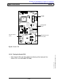
10.6
Graphics Display
The graphics display consists of the LCD, the LCD drivers, the LCD controller, the
display RAM (8 kbytes), and the fluorescent display (backlighting.
graphics display
D0 – D7
D0 – D7
WR
A0 – A12
I/O
A0 – A12
RD
r/w
R/W
CE
cc
CE
C/D
ED
RESET
FS
RAM
inverter
FS1
LCD controller
x driver
80
64
y driver
x driver
80
x driver
80
LC display
(240 x 64 pixels)
+5V
lamp
300 VAC
sec2_funcdescrip_b.fm
Fig. 39: Block diagram of the graphics display
2-54
Copyright 2000 Draeger Medical, Inc.
backlighting
RETURN TO THIS MANUAL'S TABLE OF CONTENTS
RETURN TO CD-ROM TABLE OF CONTENTS
Fabius®
10.7
Function Description
Front Panel
The front panel consists of the front frame and the membrane keypad.
10.7.1
Membrane Keypad
The membrane keypad has 15 keys (man/spont, IPPV, Pmax, VT, fIPPV, TI:TE, TIP:TI,
PEEP, upper and lower limit value setting, flow calibration, silence, standby, and 3
softkeys). The Control PCB scans the key operations.
10.7.2
Man/Spont Key
Fabius can be set to manual ventilation or spontaneous breathing by pressing the
Man/Spont key.
10.7.3
IPPV Key
Fabius can be set to intermittent positive pressure ventilation by pressing the IPPV
key.
10.7.4
Pmax Key
The inspiratory pressure limit can be set in a range of 10 hPa (mbar) to 70 hPa (mbar)
by pressing the Pmax key. A pressure higher than 40 hPa (mbar) must be confirmed
by pressing the Reset/Check key (a message is shown on the display).
10.7.5
VT Key
Copyright 2000 Draeger Medical, Inc.
sec2_funcdescrip_b.fm
After pressing the VT key, the tidal volume can be set in a range of 50 mL to 1400 mL.
10.7.6
TI:TE Key
After pressing the TI:TE key, the inspiratory/expiratory time ratio can be set in a range
of 1:3 to 2:1. The set value becomes effective at the end of the current respiratory
cycle.
10.7.7
TIP:TI Key
After pressing the Tip:Ti key, the inspiratory pause time to inspiratory time can be set
in a range of 5% to 50%. The set value becomes effective at the end of the current
respiratory cycle.
2-55
Function Description
10.7.8
RETURN TO THIS MANUAL'S TABLE OF CONTENTS
RETURN TO CD-ROM TABLE OF CONTENTS
®
Fabius
PEEP Key
After pressing the PEEP key, the positive end-expiratory pressure may be set in a
range of 1 hPa (mbar) to 15 hPa (mbar). The set value has immediate effect.
10.7.9
Limit Values Key
The limit values key is used to set the upper and the lower limit values within a certain
range.
10.7.10 Calibration Key (–0–)
After pressing the calibration key (–0–), the differential pressure sensor and the O2
sensor are calibrated. The O2 sensor is calibrated to 21 vol.% or 100 vol.%.
10.7.11 2-Min Silence Key
After pressing the 2-min silence key, the audible alarm is silenced for 2 minutes. This
status is indicated by the yellow LED in the silence key. Pressing the silence key again
during the alarm silence time will reset the audible alarm.
10.7.12 Standby Key
After pressing the standby key, the control box switches over to standby mode.
10.7.13 Menu Key
10.7.14 Screen Page Key
10.7.15 Control Knob
The control knob is used to change patient parameters (for example, PEEP, VT, or
Pmax) by turning (selection of data) and pressing (confirmation of selected data).
10.8
Interface
The interface is use to transmit the analog voltages to the pneumatics.
2-56
sec2_funcdescrip_b.fm
After pressing the screen page key, it possible to select different screen pages.
Copyright 2000 Draeger Medical, Inc.
After pressing the menu key, it is possible to configure Fabius.
RETURN TO THIS MANUAL'S TABLE OF CONTENTS
RETURN TO CD-ROM TABLE OF CONTENTS
Fabius®
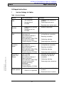
11
Function Description
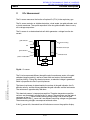
FiO2 Measurement
The O2 sensor measures the fraction of inspired O2 (FiO2) in the respiratory gas.
The O2 sensor contains an alkaline electrolyte, a lead anode, two gold cathodes, and
a plastic membrane. The spatial separation of the two gold cathodes allows to carry
out a voltage comparison.
The O2 sensor is an electrochemical cell which generates a voltage from the ion
current.
gold cathode 1
plastic housing
O2
alkaline electrolyte
gold cathode 2
lead anode
plastic membrane
–ϑ
Copyright 2000 Draeger Medical, Inc.
sec2_funcdescrip_b.fm
Fig. 40: O2 sensor
The O2 to be measured diffuses through the plastic membrane, reacts at the gold
cathodes (negative polarity) and forms lead oxide and water at the lead anode
(positive polarity). During this chemical process, an electrical voltage is generated
which is proportional to the O2 partial pressure.
The internal resistance is determined by the surface of the gold cathodes, the O2
diffusion velocity, and the distance between the gold cathodes and the lead anode.
The resistance is approximately 700 ohms.
This chemical process is temperature-sensitive. Therefore temperature-sensitive
resistors are connected in parallel to the O2 sensor. These resistors and the internal
resistance of the O2 sensor correct the measuring voltage. Due to the two gold
cathodes used in the O2 sensor cell, two different measuring voltages are generated.
These measuring voltages are compared with each other.
If the O2 sensor fails, the control box will indicate an error on the graphics display.
2-57
RETURN TO THIS MANUAL'S TABLE OF CONTENTS
RETURN TO CD-ROM TABLE OF CONTENTS
®
Fabius
Function Description
12
Flow Measurement
A moving screen (moving vane) measures the expiratory flow of the patient. A
flow-dependent pressure builds up at the moving vane. This pressure is picked up at
the differential pressure sensor (∆P). The differential pressure sensor converts the
pressure into an electronic signal and transmits this signal to the microcontroller.
P
.
flow sensor
V
moving vane
measuring line
P
∆P results from the differential pressure
(back-pressure from measuring lines 1 and 2)
measuring line
2-58
Copyright 2000 Draeger Medical, Inc.
sec2_funcdescrip_b.fm
Fig. 41: Flow measurement principle
RETURN TO THIS MANUAL'S TABLE OF CONTENTS
RETURN TO CD-ROM TABLE OF CONTENTS
Fabius®
13
Function Description
Anesthetic Vaporizer "Vapor 19.n"
Copyright 2000 Draeger Medical, Inc.
sec2_funcdescrip_b.fm
Refer to separate technical documentation of the anesthetic vaporizer "Vapor 19.n".
2-59
RETURN TO THIS MANUAL'S TABLE OF CONTENTS
RETURN TO CD-ROM TABLE OF CONTENTS
RETURN TO THIS MANUAL'S TABLE OF CONTENTS
RETURN TO CD-ROM TABLE OF CONTENTS
Fabius®
Repair Instructions
3.0 Repair Instructions
1
Service Strategy for Fabius
Table 1: Service Strategy
Where
Inspection in the
field
Test Documentation
− Test Certificate
− Service Manual,
CD-ROM
Procedure
− Checking actual condition of
machine
− Performing minor repairs
− Replacing wear and tear parts
Safety check in
the field
Repair in the
field
Copyright 2000 Draeger Medical, Inc.
sec3_repairinstruc_c.fm
Workshop at the
subsidiary,
region
Workshop in
Lübeck and
Telford
Customer,
owner, operator
− Safety check of machine
(record)
− Instructions for Use,
CD-ROM
− Machine safety check
Test Certificate
Spare parts list
Service Manual Section 5
Repair information
Service Bulletins (IDMs/TSBs)
Conversion instructions
Function diagrams, CD-ROM
− Replacing electrical, electronic,
and mechanical assemblies
Test Certificate
Spare parts list
Service Manual Section 5
Repair information
Service Bulletins (IDMs/TSBs)
Conversion instructions
Function diagrams, CD-ROM
− Replacing electrical, electronic,
and mechanical assemblies
Test Certificate
Spare parts list
Service Manual Section 5
Repair information
Service Bulletins (IDMs/TSBs)
Conversion instructions
Process and testing
instructions
Circuit diagrams
Function diagrams, CD-ROM
− Replacing and repairing all
mechanical and electrical
assemblies
− Instructions for Use
− Check list, as applicable
3-1
− Repairing assemblies
− Calibrating, adjusting
− Performing minor conversions
− Repairing assemblies
− Calibrating, adjusting
− Performing major conversions
− Calibrating, adjusting
− Performing major conversions
− Recording actual condition of
machine
− Decontamination of machine
Repair Instructions
2
RETURN TO THIS MANUAL'S TABLE OF CONTENTS
RETURN TO CD-ROM TABLE OF CONTENTS
®
Fabius
Fabius Versions
Fabius is available in several versions.
2.1
Fabius (China Version)
The first machines were built for the Chinese market. The China version runs with two
gas types: N20 and O2. Separate connections (battery/motor) are available on the
rear panel of the control box.
Risk of malfunction.
Optional features intended for the CE version might cause problems
if used in the China version (e.g. cylinder bank). Specific printed
circuit boards are used in the China version which are not identical
with those used in the CE version. The China version printed circuit
boards are available in China only.
The China version of Fabius comprises the following assemblies:
− control box
− ventilator
− circle absorption system "Fabius"
− flowmeter block
− fixed-installed anesthetic vaporizer "Vapor 19.n"
− H-ORC
sec3_repairinstruc_c.fm
− trolley
3-2
Copyright 2000 Draeger Medical, Inc.
− gas box
RETURN TO THIS MANUAL'S TABLE OF CONTENTS
RETURN TO CD-ROM TABLE OF CONTENTS
Fabius®
2.2
Repair Instructions
Fabius (CE Version)
The CE version of Fabius is manufactured for all other countries except the USA. It is
available with two gas types (N2O and O2), or three gas types (N2O, O2 and AIR).
The CE version of Fabius comprises the following assemblies:
− control box
− ventilator
− compact breathing system ("Cosy")/circle absorption system 9 Fabius
− flowmeter block
− adaptable anesthetic vaporizer "Vapor 19.n"
− S-ORC
− gas box
− trolley
2.3
Fabius (US Version)
The US version of Fabius comes with three gas types (N2O, O2 and AIR). The
flowmeters in the flowmeter block are arranged differently than those of the Fabius CE
version and have also a different color coding.
The US version of Fabius comprises the following assemblies:
− control box
− ventilator
− compact breathing system ("Cosy")/circle absorption system 9 Fabius
Copyright 2000 Draeger Medical, Inc.
sec3_repairinstruc_c.fm
− flowmeter block
− adaptable anesthetic vaporizer "Vapor 19.n"
− S-ORC
− gas box
− trolley
3-3
RETURN TO THIS MANUAL'S TABLE OF CONTENTS
RETURN TO CD-ROM TABLE OF CONTENTS
®
Fabius
Repair Instructions
3
Fabius Assemblies
1
6
O2 +
S-ORC
2
3
5
Fabius
4
Fig. 1: Front view of Fabius with compact breathing system "Cosy"
Control box
2
Flowmeter block
3
Anesthetic vaporizer(s) Vapor 19.n
4
Trolley
5
Compact breathing system "Cosy"
6
Ventilator
sec3_repairinstruc_c.fm
1
3-4
Copyright 2000 Draeger Medical, Inc.
Key
RETURN TO THIS MANUAL'S TABLE OF CONTENTS
RETURN TO CD-ROM TABLE OF CONTENTS
Fabius®
Repair Instructions
1
2
7
O2 +
3
S-ORC
4
max. 134 C
10
50
5
30
70
Fabius
6
5
Fig. 2: Front view of Fabius with circle absorption system 9 Fabius
Copyright 2000 Draeger Medical, Inc.
sec3_repairinstruc_c.fm
Key
1
Circle absorption system 9 Fabius
2
Control box
3
Flowmeter block
4
Anesthetic vaporizer(s) Vapor 19.n
5
Trolley
6
Breathing bag
7
Ventilator
3-5
RETURN TO THIS MANUAL'S TABLE OF CONTENTS
RETURN TO CD-ROM TABLE OF CONTENTS
®
Fabius
Repair Instructions
4
Fabius Assemblies (rear view)
P
1 AT
9
ON
1 AT
OFF
Paw
8
Interface M
V-Sensor
1
15
9
Interface C
O2-Sensor
1
2
3
4
8
5
6
7
Fig. 3: Fabius assemblies (rear view)
Gas box cover
2
O2 input port
3
N2O input port
4
AIR input port
5
O2 cylinder input port
6
N2O cylinder input port
7
O2 output port (ejector)
8
Cover plate of pneumatics and (optional) rechargeable battery
9
Control box
3-6
Copyright 2000 Draeger Medical, Inc.
1
sec3_repairinstruc_c.fm
Key
RETURN TO THIS MANUAL'S TABLE OF CONTENTS
RETURN TO CD-ROM TABLE OF CONTENTS
Fabius®
5
Repair Instructions
Removing Assemblies from Gas Box
1
2
3
1
1
2
Fig. 4: Cover plates on rear panel of Fabius
Table 2: Assembly Removal Steps
Copyright 2000 Draeger Medical, Inc.
sec3_repairinstruc_c.fm
Assembly
Remove
screws
Pneumatics (Pneumatics Control PCB,
pump, PEEP valve, pressure sensor)
2
Gas box
1
Ventilator
Swivel out
door
3
3-7
Repair Instructions
6
RETURN TO THIS MANUAL'S TABLE OF CONTENTS
RETURN TO CD-ROM TABLE OF CONTENTS
®
Fabius
Debug Mode (software 1.00)
The following information is displayed in the debug mode during normal operation of
Fabius: system data, measured values, error log. One debug mode page is available.
System data cannot be changed.
6.1
Accessing the Debug Mode (software 1.00)
The debug mode can be accessed from any operating mode.
• Press the “Menu” key.
• Select “keycode” by turning rotary knob.
• Confirm selection by pressing rotary knob.
The selected numeric code is displayed on black background.
• Select keycode “1” by turning rotary knob one position clockwise.
• Confirm selection by pressing rotary knob.
• Press rotary knob again.
An additional screen page is displayed. Fabius remains in the normal mode and can
be operated as desired.
6.2
Exiting the Debug Mode (software 1.00)
• Press the “Menu” key.
• Select “keycode” by turning rotary knob.
The selected numeric code is displayed on black background.
• Select keycode “0” by turning rotary knob one position counter-clockwise.
• Press rotary knob again.
Fabius is now in the normal operating mode.
3-8
sec3_repairinstruc_c.fm
• Confirm selection by pressing rotary knob.
Copyright 2000 Draeger Medical, Inc.
• Confirm selection by pressing rotary knob.
RETURN TO THIS MANUAL'S TABLE OF CONTENTS
RETURN TO CD-ROM TABLE OF CONTENTS
Fabius®
Repair Instructions
6.3
Debug Mode Table (software 1.00)
Table 3: Debug Mode (software 1.00)
Pressure sensor value (Paw) in mbar
(default)
P
Plateau pressure in mbar
Plat
XXX (varies with system
settings)
XXX (0 to 738)
Flow sensor A/D converter value (default)
Supply voltage (approx. 27 V) in volts
FL
U_24
XXX (0 L/min 512)
Oxygen sensor channel 1 in mV
Supply voltage (+12 V) in volts
O2_1
U+12
XXX (9 – 20)
Supply voltage (–12 V) in volts
O2_2
U–12
XXX (9 – 20)
XX.X (12.0 ± 2.0)
Expiratory Vt during inspiration (mL)
EEPROM error code
Vtix
XXX (varies with system settings,
ideally 0)
EEPR
Pressure sensor calibration value
Battery charging current in amperes
CalP
LADI
XXX (704 – 768)
XXXX
X.X (approx. 0.0 – 2.0)
Flow sensor calibration value
Motor current in amperes
CalF
MOTI
XXX (482 – 542)
CalO
X.X (0.0 – 2.5)
Pressure between rolling seals in mbar
PMEM
Copyright 2000 Draeger Medical, Inc.
XX.X (12.0 ±2.0)
Oxygen sensor channel 2 in mV
Oxygen sensor calibration value (21% O2)
sec3_repairinstruc_c.fm
XX.X (22.5 – 35.0)
XXX (200 ±50)
XX (39 – 113)
Monitoring error code
Ventilation error
MONI
VENT
XXXX
Calculation from controller data (set values):
Tidal volume (mL)
frequency (1/min)
V:
F:
XXXX
XX
System temperature in °C
T
Error log
(most recent error entry on extreme left)
LOG
XX XX XX XX XX XX XX XX XX
3-9
XXXX
XX (max. 60°C)
Repair Instructions
7
RETURN TO THIS MANUAL'S TABLE OF CONTENTS
RETURN TO CD-ROM TABLE OF CONTENTS
®
Fabius
Debug Mode (software 2.00)
The following information is displayed in the debug mode during normal operation of
Fabius: system data, measured values, error log. Two pages are available in this
debug mode. System data cannot be changed.
7.1
Accessing the Debug Mode (software 2.00)
The debug mode can be accessed from any operating mode.
• Press the “Menu” key.
• Select “keycode” by turning rotary knob.
• Confirm selection by pressing rotary knob.
The selected numeric code is displayed on black background.
• Select keycode “1” (debug mode) or “2” (flow curve) by turning rotary knob one
position clockwise.
• Confirm selection by pressing rotary knob.
• Press rotary knob again.
An additional screen page is displayed. Fabius remains in the normal operating mode
and can be operated as desired.
7.2
Exiting the Debug Mode (software 2.00)
• Press the “Menu” key.
• Select “keycode” by turning rotary knob.
The selected numeric code is displayed on black background.
• Select keycode “0” by turning rotary knob one position counter-clockwise.
• Press rotary knob again.
Fabius is now in the normal operating mode.
3-10
sec3_repairinstruc_c.fm
• Confirm selection by pressing rotary knob.
Copyright 2000 Draeger Medical, Inc.
• Confirm selection by pressing rotary knob.
RETURN TO THIS MANUAL'S TABLE OF CONTENTS
RETURN TO CD-ROM TABLE OF CONTENTS
Fabius®
Repair Instructions
7.3
Debug Mode Table (software 2.00)
7.3.1
Debug Mode (software 2.00), Page 1 (keycode "1")
Error log (most recent error entry on extreme left)
LOG XX XX XX XX XX XX XX XX XX XX XX XX XX XX
A/D pressure sensor value in mbar/
calibration value (default) in mbar
Motor current in amperes
(normal operating range 0 to 1.5 A)
P XXX (650 to 825) / XXX (738 = 0hPa)
Imot
Flow sensor A/D converter value /
calibration value (default)
Pressure between the rolling seals in
hPa (normal operating range 120 to
250 hPa)
X.XX
F1 XXX (482 to 542) / XXX (0 L/min = 512)
Pvac
Oxygen sensor channel 1 in mV
Oxygen sensor channel 2 in mV
(normal operating range 5mV to 105 mV)
O2_ XXX / XXX
System temperature in °C
(normal operating range 10 to 70 °C)
Oxygen sensor calibration status
Oxygen sensor calibration value (21% O2)
(Calibration value in mV
Frequency:
calculated from piston movement (1/min)
(normal operating range 6 to 60 1/min)
CAL
f_v:
nnnn (XXX) /
Copyright 2000 Draeger Medical, Inc.
Elapsed time meter
(full hours displayed)
sec3_repairinstruc_c.fm
XXX
Tem XX
XX
h XXXXXXXXX
Tidal volume
calculated from piston movement
(normal operating range 50 to 1400 mL)
V_v: XXXX
Supply voltage (approx. 27 V) in volts
(normal operating range 23.0 V to 35.0 V)
U+24 XX.X
Motor type, jumper position: Power PCB
(motor type: JC = Mavillor, J8 = GEC)
XXRXX JC
Supply voltage (+12 V) in volts
(normal operating range 10.8 V to 13.2 V)
U+12 XX.X (12.0 V ±2.0 V)
Monitoring error code
Supply voltage (–12 V) in volts
(normal operating range –10.8 V to –13.2 V)
Ventilator error code
U–12
VEN
XX.X
Battery charging current in amperes
(normal operating range –2 to 3 A)
Ibat X.X
MON
XXXX
XXXX
EEPROM error code
EEP
XXXX
Control PCB software version
XXMXX J6
Rev. A
3-11
RETURN TO THIS MANUAL'S TABLE OF CONTENTS
RETURN TO CD-ROM TABLE OF CONTENTS
®
Fabius
Repair Instructions
Flow Curve (software 2.00), Page 2 (Keycode “2”)
(Quit key: toggles between 1:1
and 1:6 resolution)
Measured tidal volume in mL
(normal operating range: 0 to 9999 mL)
Vte
XXXX mL
Expiratory VT during inspiration (in mL, ideally: 0)
(normal operating range: 0 to 9999 mL)
Vtix
XXXX mL
Expiratory peak flow in L/min
(normal operating range: 0 to 150 L/min)
Flep XXX L/min
Tidal volume corresponding to ventilator’s I/E
phase (in mL)
(normal operating range: 0 to 9999 mL)
Vtev
XXXX mL
Plateau pressure in hPa
(normal operating range 0 to 99 hPa)
Plat
XX hPa
3-12
Copyright 2000 Draeger Medical, Inc.
Flow curve
sec3_repairinstruc_c.fm
7.3.2
RETURN TO THIS MANUAL'S TABLE OF CONTENTS
RETURN TO CD-ROM TABLE OF CONTENTS
Fabius®
8
Repair Instructions
"Ventilator" (VEN) Display Field
Overview: VEN
0000 ==> no errors
0001 – 0008 ==> motor errors
0040 and 0080 ==> pump errors
0100 ==> temperature error
1000 and 2000 ==> communication errors
4000 ==> current error (motor current is too high)
Error
Error Description
Possible Cause
0001
No incrementing.
Motor open or not connected.
Incremental encoder not
connected.or needs replacement
0002
End position switch activated
continuously.
Light barrier not connected.or needs
replaced
0004
End position switch not detected.
External light interference, or light
barrier needs replaced.
0008
Motor direction incorrect (use only
upon power-on of Fabius).
Motor conductors reversed. Phase
conductors of incremental encoder
reversed.
0010
24 V supply not available.
Controller relay (Power PCB)
switched off. Fuse F4 on Power
Supply PCB open.
0040
Diaphragm pressure too low.
Ventilator cover open.
Vacuum hose not connected.
Diaphragm pump needs replaced
0080
Diaphragm pressure too high.
Diaphragm pressure sensor
connector not connected.
0100
Temperature too high.
NTC error on Power PCB. Fan not
running
0200
I/E signal from controller (Power
PCB) not in expected range.
Ventilation frequency or inspiratory
time out of tolerance. Motor and/or
motor control error.
0400
Ventilator piston does not work in
IPPV mode.
Motor open or not connected.
Power PCB needs replaced
0800
Data error (gain, offset, from PEEP
valve)
EEPROM or RAM error. New PEEP
valve calibration.
Copyright 2000 Draeger Medical, Inc.
sec3_repairinstruc_c.fm
0020
Rev. A
3-13
RETURN TO THIS MANUAL'S TABLE OF CONTENTS
RETURN TO CD-ROM TABLE OF CONTENTS
®
Fabius
Repair Instructions
1000
Communication error from
Control PCB to Power PCB.
Line interruption in ribbon cable,
bent connector.
2000
Communication error from Power
PCB to Control PCB.
Line interruption. Power PCB does
not work (see error 1000).
4000
Motor current temporarily too high.
Incremental encoder lost
increments. Contamination,
scratches, light barrier needs
replaced
8000
Motor current continuously too high.
Power amplifier needs replaced.
Motor open.
9
"Monitor" (MON) Display Field
Overview: MON
Error Description
Possible Cause
0001
FiO2 sensor voltage too low.
O2 sensor needs replaced.
O2 sensor calibrated incorrectly.
0002
FiO2 sensor voltage too high.
O2 sensor needs replaced.
O2 sensor calibrated incorrectly.
0004
FiO2 measured values outside
permissible range.
O2 sensor needs replaced
0008
FiO2 time-out during calibration.
O2 sensor needs replaced.
Sensor not yet stabilized.
Calibration of O2 sensor at changing
O2 concentration or O2 concentration
not corresponding to calibration mode
(21%/100%).
0010
FiO2/relative error between FiO2
sensor channels > 25%.
O2 sensor needs replaced.
0020
FiO2 calibration constant from
EEPROM incorrect.
O2 sensor not yet calibrated.
Data loss in the EEPROM.
0040
FiO2/coding for calibration.
Current error occurred during
calibration.
3-14
Copyright 2000 Draeger Medical, Inc.
Error
sec3_repairinstruc_c.fm
0000 ==> no errors
00XX ==> O2 sensor error
0X00 ==> pressure sensor error
X000 ==> flow sensor error
RETURN TO THIS MANUAL'S TABLE OF CONTENTS
RETURN TO CD-ROM TABLE OF CONTENTS
Repair Instructions
0080
One calibration value lost during
operation (pressure sensor, flow
sensor, FiO2 sensor calibration
values).
RAM error.
Electromagnetic interference.
0100
Pressure above maximum value for
more than 5 seconds.
Pressure sensor needs replaced.
Continuously high pressure.
0200
Pressure below minimum value for
more than 5 seconds.
Pressure sensor needs replaced.
Continuously low pressure.
0400
Pressure/calibration error.
Pressure sensor needs replaced.
Pressure during calibration higher than
or lower than 0 mbar.
0800
Pressure/plausibility error during
respiratory phase.
Software error.
1000
Flow above maximum value for
more than 5 seconds (<150 L).
Flow sensor or differential pressure
sensor (flow) needs replaced
Continuously high expiratory flow.
2000
Flow below minimum value for more
than 5 seconds.
Flow sensor or differential pressure
sensor (flow) needs replaced.
Continuously high expiratory flow.
4000
Flow/calibration error.
Flow sensor or differential pressure
sensor (flow)needs replaced.
Flow at flow sensor during calibration
higher than or lower than 0 L/min.
8000
Flow/plausibility error during
respiratory phase.
Respiratory phase detection software
error.
Copyright 2000 Draeger Medical, Inc.
sec3_repairinstruc_c.fm
Fabius®
3-15
RETURN TO THIS MANUAL'S TABLE OF CONTENTS
RETURN TO CD-ROM TABLE OF CONTENTS
®
Fabius
Repair Instructions
10
"EEPROM" (EEP) Display Field
Overview: EEP
Error Description
Possible Cause
0001
Read error.
System configuration
(device configuration)
Data error.
EEPROM needs replaced.
0002
Read error.
System data (values stored in the
event of a power failure)
Data error.
EEPROM needs replaced.
Data stored incorrectly in the event of a
power failure.
0004
Read error.
User configuration (user settings)
Data error.
EEPROM needs replaced.
0008
Read error.
Settings of ventilation (last setting in
the event of a power failure)
Data error.
EEPROM needs replaced.
Data stored incorrectly in the event of a
power failure.
0010
Read error.
Monitoring limit values (last setting
in the event of a power failure)
Data error.
EEPROM needs replaced.
Data stored incorrectly in the event of a
power failure.
0020
Read error.
Monitoring calibration values.
Ventilation calibration values.
Data error.
EEPROM needs replaced.
0040
Read error.
Error log.
Data error.
EEPROM needs replaced.
0080
For internal use.
Data error.
EEPROM needs replaced.
0100
Write error.
System configuration
(device configuration)
Data error.
EEPROM needs replaced.
0200
Write error.
System data (values stored in the
event of a power failure)
Data error.
EEPROM needs replaced.
Data stored incorrectly in the event of a
power failure.
0400
Write error.
User configuration (user settings)
Data error.
EEPROM needs replaced.
3-16
Copyright 2000 Draeger Medical, Inc.
Error
sec3_repairinstruc_c.fm
0000 ==> no error
XX00 ==> write error
00XX ==> read error
RETURN TO THIS MANUAL'S TABLE OF CONTENTS
RETURN TO CD-ROM TABLE OF CONTENTS
Repair Instructions
0800
Write error.
Ventilation settings (last setting in
the event of a power failure)
Data error.
EEPROM needs replaced.
Data stored incorrectly in the event of a
power failure.
1000
Write error.
Monitoring limit values (last setting
in the event of a power failure)
Data error.
EEPROM needs replaced.
Data stored incorrectly in the event of a
power failure.
2000
Write error.
Monitoring calibration values.
Ventilation calibration values.
Data error.
EEPROM needs replaced.
4000
Error log write error
Data error.
EEPROM needs replaced.
8000
For internal use.
Data error.
EEPROM needs replaced.
Copyright 2000 Draeger Medical, Inc.
sec3_repairinstruc_c.fm
Fabius®
3-17
RETURN TO THIS MANUAL'S TABLE OF CONTENTS
RETURN TO CD-ROM TABLE OF CONTENTS
®
Fabius
Repair Instructions
Error Log
Error Description
Possible Cause
0
No error
11
Reset; cause unknown
Hardware error. Electromagnetic
interference. EEPROM needs
replaced
14
RAM (Control PCB)
RAM needs replaced.
15
EPROM (Control PCB)
EPROM needs replaced.
16
Watchdog reset (Control PCB)
Hardware error. Software error.
Watchdog time exceeded.
17
A/D converter
Error during A/D conversion.
18
Graphics display
Graphics display or connector
needs replaced.
21
Battery
Wrong battery installed or
installed battery flat.
22
Analog voltage
Error in ±12 V voltage supply.
Control PCB needs replaced.
23
Supply voltage
Battery exhausted during power
supply from battery.
31
EEPROM*
Read/write error during system
start-up. EEPROM needs
replaced. Data error.
32
EEPROM* write error
Error during EEPROM writing.
EEPROM needs replaced. Data
error.
33
EEPROM* read error
Error during EEPROM reading.
EEPROM needs replaced. Data
error.
34
RAM backup error
Error while reading internal RAM
data during system start-up.
35
Data check error/system reset
occurs
Checksum of settings or
operating mode incorrect.
36
Communication error
RAM locations inverted or needs
replaced.
37
Calibration value check error (O2
sensor, pressure sensor, flow
sensor, PEEP valve)
EEPROM error. RAM error.
Standard values are being used.
Calibration required.
* Later models do not have an EEPROM and require board replacement.
Rev. A
3-18
Copyright 2000 Draeger Medical, Inc.
Error
sec3_repairinstruc_c.fm
11
RETURN TO THIS MANUAL'S TABLE OF CONTENTS
RETURN TO CD-ROM TABLE OF CONTENTS
Fabius®
41
Repair Instructions
Motor error
Ventilator drive error: no
incrementing possible. End
position switch activated
continuously. End position switch
not detected.
For current code and error
description, see display field
“VEN”.
Error may also occur if Fabius
is operated while ventilator is
not connected.
42
24 V operating voltage
Relay of Power PCB switched off.
Open fuse F4 on Power Supply
PCB.
43
End position of actuator exceeded.
Incremental encoder lost
increments.
44
Diaphragm pressure too low.
Ventilator cover open.
Vacuum hose disconnected.
Diaphragm pump needs replaced.
45
Diaphragm pressure too high.
Diaphragm pressure sensor
connector disconnected.
Diaphragm pressure sensor
needs replaced.
Copyright 2000 Draeger Medical, Inc.
sec3_repairinstruc_c.fm
Error may also occur if Fabius
is operated while ventilator is
not connected.
46
System temperature too high.
Error occurred on Power PCB.
47
Time-out in IPPV/ventilation not
OK.
Motor open or disconnected.
Power PCB needs replaced.
Error may also occur if Fabius
is operated while ventilator is
not connected.
48
SIO error
There is an interruption of the
communication line.
The controller (Power PCB) does
not function.
49
Motor current too high.
Power amplifier needs replaced.
Motor open.
3-19
RETURN TO THIS MANUAL'S TABLE OF CONTENTS
RETURN TO CD-ROM TABLE OF CONTENTS
®
Fabius
Repair Instructions
51
Ventilation frequency or inspiratory
time out of tolerance.
Motor does not meet
specifications.
Ventilator needs replaced.
RAM (Power PCB)
RAM needs replaced.
82
EPROM (Power PCB)
EPROM needs replaced.
83
Watchdog reset (Power PCB)
Software error. Duration
exceeded.
sec3_repairinstruc_c.fm
81
3-20
Copyright 2000 Draeger Medical, Inc.
Error may also occur if Fabius
is operated while ventilator is
not connected.
RETURN TO THIS MANUAL'S TABLE OF CONTENTS
RETURN TO CD-ROM TABLE OF CONTENTS
Fabius®
12
Repair Instructions
DrägerService Mode (software 1.00)
The DrägerService Mode is used to calibrate critical
components (Paw sensor, PEEP valve). The DrägerService
Mode should only be used by qualified and authorized
DrägerService technicians.
DrägerService Mode allows the following actions:
− calibrating the pressure sensor (Paw)
− deleting error log entries
− reading out/resetting elapsed hours meter
− selecting the function (monitor or ventilator or monitor and ventilator)
− initializing Fabius (calibration values, elapsed hours, etc.)
12.1
Accessing the DrägerService Mode (software 1.00)
The DrägerService Mode can only be accessed while Fabius is in the standby mode.
• Press the “Menu” key.
• Select “keycode” by turning rotary knob.
• Confirm by pressing rotary knob.
The respective number is displayed on black background.
• Select keycode “112” by turning rotary knob clockwise.
Copyright 2000 Draeger Medical, Inc.
sec3_repairinstruc_c.fm
• Confirm by pressing rotary knob.
An additional screen page is displayed.
12.2
Exiting the DrägerService Mode (software 1.00)
• Switch the control box off.
3-21
Repair Instructions
12.3
RETURN TO THIS MANUAL'S TABLE OF CONTENTS
RETURN TO CD-ROM TABLE OF CONTENTS
®
Fabius
DrägerService Mode (software 1.00) Screen Display
SERVICE
Calibration pressure
Calibration peep valve
Reset logbook
Reset operating hours
Function
Init system *
DISABLED
EMPTY
LOST
XXXXXXXXX
MON. + VENT.
Fig. 5: DrägerService Mode screen display (software 1.00)
* Initialization of Fabius
3-22
Copyright 2000 Draeger Medical, Inc.
sec3_repairinstruc_c.fm
Risk of loss of calibration data when selecting menu item "Init
system". Select menu item “Init system” only if you want to
store new calibration data or if you have replaced the Control
PCB.
RETURN TO THIS MANUAL'S TABLE OF CONTENTS
RETURN TO CD-ROM TABLE OF CONTENTS
Fabius®
13
Repair Instructions
DrägerService Mode (software 2.00)
The DrägerService Mode is used to calibrate critical
components (Paw sensor, PEEP valve). The DrägerService
Mode should only be used by qualified and authorized
DrägerService technicians.
DrägerService Mode allows the following actions:
− calibrating the pressure sensor (Paw)
− calibrating the PEEP valve
− deleting error log entries
− reading out/resetting elapsed hours meter
− selecting the function (monitor or ventilator or monitor and ventilator)
− initializing Fabius (calibration values, elapsed hours, etc.)
13.1
Accessing the DrägerService Mode (software 2.00)
The DrägerService Mode can only be accessed while Fabius is in the standby mode.
• Press the “Menu” key.
• Select “keycode” by turning rotary knob.
• Confirm by pressing rotary knob.
The respective number is displayed on black background.
Copyright 2000 Draeger Medical, Inc.
sec3_repairinstruc_c.fm
• Select keycode “112” by turning rotary knob clockwise.
• Confirm by pressing rotary knob.
An additional screen page is displayed.
13.2
Exiting the DrägerService Mode (software 2.00)
• Switch the control box off.
3-23
Repair Instructions
13.3
RETURN TO THIS MANUAL'S TABLE OF CONTENTS
RETURN TO CD-ROM TABLE OF CONTENTS
®
Fabius
DrägerService Mode (software 2.00) Screen Display
SERVICE
Reset logbook
Function
Cal. peepvalve
Cal. pressure
Init system *
MON. + VENT.
EMPTY
Peep tuning:
G_h 0_h: G_1 0_1
XX XXX XX XXX
P/PWM**
0 0 0 0
0 0
0 0
Fig. 6: DrägerService Mode screen display (software 2.00)
* Initialization of Fabius
** P (pressure) corresponds to PWM (pulse width modulation) ratio
3-24
Copyright 2000 Draeger Medical, Inc.
sec3_repairinstruc_c.fm
Risk of loss of calibration data when selecting menu item "Init
system". Select menu item “Init system” only if you want to
store new calibration data or if you have replaced the Control
PCB.
RETURN TO THIS MANUAL'S TABLE OF CONTENTS
RETURN TO CD-ROM TABLE OF CONTENTS
Fabius®
14
Repair Instructions
General Information About the Control Box
Any of the following assemblies must be replaced completely in case of
malfunctioning:
− power cable
− mains filter
− ON/OFF switch
− fuses
− power transformer
− Power Supply PCB
− Power PCB
− Control PCB
− differential pressure sensor (flow)
− pressure sensor (Paw)
− Display PCB
− backlighting lamp
− rotary knob
Copyright 2000 Draeger Medical, Inc.
sec3_repairinstruc_c.fm
− rechargeable battery
3-25
RETURN TO THIS MANUAL'S TABLE OF CONTENTS
RETURN TO CD-ROM TABLE OF CONTENTS
®
Fabius
Repair Instructions
14.1
Removing the Control Box from the Gas Box
• Switch control box off using ON/OFF switch (ON/OFF switch is located on rear
panel of control box).
• Disconnect cable and hose connections 1 to 7 (see figure below) and remove
control box.
• Loosen screw of cable clamp 8 and thread power cord out of cable clamp.
1
ON/OFF switch
2
3
Paw
V-Sensor
1 AT
ON
OFF
1 AT
8
1
9
15
Interface M
8
6
7
m
Interface C
O2-Sensor
4
5
Fig. 7: Rear view of the control box, disconnecting cable and hose connections
• Loosen knurled screws 9.
9
P
1 AT
ON
Paw
8
Interface M
V-Sensor
V-Sensor
1
15
9
Interface C
O2-Sensor
9
Fig. 8: Rear view of Fabius, loosening knurled screws
3-26
sec3_repairinstruc_c.fm
O2-Sensor
Copyright 2000 Draeger Medical, Inc.
1 AT
OFF
RETURN TO THIS MANUAL'S TABLE OF CONTENTS
RETURN TO CD-ROM TABLE OF CONTENTS
Fabius®
Repair Instructions
• Lift control box 1 at rear and remove control box 1 from front mount.
1
O2 +
S-ORC
Fabius
Fig. 9: Front view of Fabius, removing control box from front
Copyright 2000 Draeger Medical, Inc.
sec3_repairinstruc_c.fm
• Place control box 1 on a stable surface.
3-27
RETURN TO THIS MANUAL'S TABLE OF CONTENTS
RETURN TO CD-ROM TABLE OF CONTENTS
®
Fabius
Repair Instructions
14.2
Removing the Top Cover from the Control Box
Electrostatic discharge can damage electrostatic sensitive
devices. Use a static-dissipative mat and a wrist strap when
handling electrostatic sensitive devices.
• Remove lateral screws 1 from control box 2 and lift top cover 3 in direction of A
and away from control box 2.
• Place top cover 3 of control box 2 aside.
A
3
1
1
man./
spont.
IPPV
IPPV
Paw [mbar]
60
40
20
0
Pmax
FiO2
MV
Paw
VT
fIPPV
TI:TE
24
7.9
28
TIP:TI
2
80
21
12.0
3.0
40
8
PEEP
Menu
1..2..
0
3-28
Copyright 2000 Draeger Medical, Inc.
sec3_repairinstruc_c.fm
Fig. 10: Removing top cover of control box
RETURN TO THIS MANUAL'S TABLE OF CONTENTS
RETURN TO CD-ROM TABLE OF CONTENTS
Fabius®
14.3
Repair Instructions
Control Box Assemblies
11
1
10
2
9
3
8
4
6
7
Fig. 11: Top view of the control box (top cover removed)
Copyright 2000 Draeger Medical, Inc.
sec3_repairinstruc_c.fm
Key
1
Power Supply PCB
2
Mains filter
3
Power transformer
4
Front (front frame and membrane keypad)
5
Rotary knob
6
Power PCB
7
Display PCB/backlighting lamp
8
Control PCB
9
Rechargeable battery
10
Differential pressure sensor (flow measurement)
11
Pressure sensor (airway pressure "Paw")
3-29
5
RETURN TO THIS MANUAL'S TABLE OF CONTENTS
RETURN TO CD-ROM TABLE OF CONTENTS
®
Fabius
Repair Instructions
14.4
Control Box (Rear Panel)
1
3
2
4
1 AT
ON
OFF
1 AT
V-Sensor
Paw
8
1
9
15
Interface M
9
8
m
Interface C
7
O2-Sensor
6
5
Fig. 12: Rear view of the control box
Power receptacle with mains fuses
2
ON/OFF switch
3
Equipotential bonding pin (ground)
4
Flow sensor port
5
Oxygen sensor port
6
Pressure sensor port (Paw)
7
Pneumatics interface
8
Motor control interface
9
Power-cord cable clamp
sec3_repairinstruc_c.fm
1
3-30
Copyright 2000 Draeger Medical, Inc.
Key
RETURN TO THIS MANUAL'S TABLE OF CONTENTS
RETURN TO CD-ROM TABLE OF CONTENTS
Fabius®
14.5
Repair Instructions
Power Transformer
In case of repair, replace the complete power transformer.
14.5.1
Testing the Power Transformer Output Voltage
• Switch control box off using ON/OFF switch (ON/OFF switch is located on rear
panel of control box).
• Unplug power cord from AC outlet.
• Check mains fuses of the control box (mains fuses are located on rear panel of
control box).
• If mains fuses are OK, proceed as follows:
Electrostatic discharge can damage electrostatic sensitive
devices. Use a static-dissipative mat and a wrist strap when
handling electrostatic sensitive devices.
• Remove control box from trolley (see control box chapter "Removing the Control
Box from the Gas Box").
• Remove lateral screws 1 from control box 2 and lift top cover 3 in direction of A
and away from control box 2.
• Place top cover 3 of control box 2 aside.
A
Copyright 2000 Draeger Medical, Inc.
sec3_repairinstruc_c.fm
3
1
1
man./
spont.
IPPV
IPPV
Paw [mbar]
60
40
20
0
Pmax
FiO2
MV
Paw
VT
fIPPV
TI:TE
24
7.9
28
TIP:TI
2
80
21
12.0
3.0
40
8
Fig. 13: Removing top cover of the control box
3-31
Menu
1..2..
PEEP
0
RETURN TO THIS MANUAL'S TABLE OF CONTENTS
RETURN TO CD-ROM TABLE OF CONTENTS
®
Fabius
Repair Instructions
• Plug power cord into AC outlet.
• Switch control box on.
• Using a multimeter, measure the power transformer output voltage (it should be
approx. 40 VAC).
• If the power transformer output voltage is not approx. 40 VAC, check fuses, if
fuses are OK, replace power transformer (see "Dismounting/Replacing the Power
Transformer").
T4L
X20
T3,15L
X4
T1,6L
T2,5L
X6
X8
40 VAC
X2
3-32
Copyright 2000 Draeger Medical, Inc.
sec3_repairinstruc_c.fm
Fig. 14: Power Supply PCB, measuring the power transformer output voltage
RETURN TO THIS MANUAL'S TABLE OF CONTENTS
RETURN TO CD-ROM TABLE OF CONTENTS
Fabius®
14.5.2
Repair Instructions
Dismounting/Replacing the Power Transformer
• Switch control box off using ON/OFF switch (ON/OFF switch is located on rear
panel of control box).
• Unplug power cord from AC outlet.
Electrostatic discharge can damage electrostatic sensitive
devices. Use a static-dissipative mat and a wrist strap when
handling electrostatic sensitive devices.
• Remove control box from trolley (see "Removing the Control Box from the Gas
Box").
• Remove lateral screws 1 from control box 2 and lift top cover 3 in direction of A
and away from control box 2.
• Place top cover 3 of control box 2 aside.
A
3
1
1
Copyright 2000 Draeger Medical, Inc.
sec3_repairinstruc_c.fm
man./
spont.
IPPV
IPPV
Paw [mbar]
60
40
20
0
Pmax
FiO2
MV
Paw
VT
fIPPV
TI:TE
24
7.9
28
TIP:TI
2
80
21
12.0
3.0
40
8
Fig. 15: Removing top cover of the control box
3-33
Menu
1..2..
PEEP
0
RETURN TO THIS MANUAL'S TABLE OF CONTENTS
RETURN TO CD-ROM TABLE OF CONTENTS
®
Fabius
Repair Instructions
• Disconnect cable connector 1 of power transformer from the Power Supply PCB.
T4L
X20
T3,15L
X4
1
T1,6L
T2,5L
X6
X8
X2
Fig. 16: View of the Power Supply PCB, disconnecting the cable connector
sec3_repairinstruc_c.fm
2
2
Fig. 17: Disconnecting cable lugs from connectors of mains filter
3-34
Copyright 2000 Draeger Medical, Inc.
• Disconnect both power transformer cable lugs 2 from connectors of mains filter.
RETURN TO THIS MANUAL'S TABLE OF CONTENTS
RETURN TO CD-ROM TABLE OF CONTENTS
Fabius®
Repair Instructions
• Remove screws 1 and place device mounting plates 2 aside.
1
2
2
1
Fig. 18: Right hand side of control box, removing device mounting plates
• Remove screws 3.
3
3
Fig. 19: Right hand side of control box, removing fixing screws of power transformer
Copyright 2000 Draeger Medical, Inc.
sec3_repairinstruc_c.fm
• Replace the power transformer with a new one and secure new power
transformer to control box using screws 3.
• Mount device mounting plates 2 to control box (see Figure "Right hand side of
control box, removing device mounting plates."
• Connect both cable lugs of power transformer to connectors of mains filter.
3-35
RETURN TO THIS MANUAL'S TABLE OF CONTENTS
RETURN TO CD-ROM TABLE OF CONTENTS
®
Fabius
Repair Instructions
Check that new power transformer is wired according to
country-specific requirements. Adjust voltage range if
necessary (see Figure "Adjusting voltage range on power
transformer".
40 VAC
110 VAC
110 V voltage range
40 VAC
230 VAC
230 V voltage range
Fig. 20: Adjusting voltage range on power transformer
Make sure to use the correct fuses for 110 V or 230 V supply:
100 V = 2 AT, 230 V = 1 AT
• Connect power transformer cable connector to connection 1 of
Power Supply PCB.
X20
T3,15L
X4
1
X8
X2
Fig. 21: Power Supply PCB; connecting power transformer cable connector
3-36
sec3_repairinstruc_c.fm
T1,6L
T2,5L
X6
Copyright 2000 Draeger Medical, Inc.
T4L
RETURN TO THIS MANUAL'S TABLE OF CONTENTS
RETURN TO CD-ROM TABLE OF CONTENTS
Fabius®
Repair Instructions
• Mount top cover to control box.
• Mount control box to Fabius trolley.
• Connect hoses and cables to control box.
• Check control box function according to Test Certificate.
14.6
Power Supply PCB
14.6.1
General Information About the Power Supply PCB
In case of malfunctioning, replace mains fuses (located in the power receptacle
assembly), fuses F1, F2, F4, and F5 (located on Power Supply PCB), or complete
Power Supply PCB.
14.6.2
Testing the Power Supply PCB in the Debug Mode
• Check voltages of Power Supply PCB in the debug mode:
U +24 = +24 V (23.0 V through 35.0 V)
U +12 = +12 V (10.8 V through 13.2 V)
U –12 = –12 V (–10.8 V through –13.2 V)
14.6.3
Testing the Power Supply PCB
• Switch control box off using ON/OFF switch (ON/OFF switch is located on rear
panel of control box).
Copyright 2000 Draeger Medical, Inc.
sec3_repairinstruc_c.fm
• Remove control box from trolley (see "Removing the Control Box from the Gas
Box").
Electrostatic discharge can damage electrostatic sensitive
devices. Use a static-dissipative mat and a wrist strap when
handling electrostatic sensitive devices.
3-37
RETURN TO THIS MANUAL'S TABLE OF CONTENTS
RETURN TO CD-ROM TABLE OF CONTENTS
®
Fabius
Repair Instructions
• Remove lateral screws 1 from control box 2 and lift top cover 3 in direction of A
and away from control box 2.
• Place top cover 3 of control box 2 aside.
A
3
1
1
man./
spont.
IPPV
IPPV
Paw [mbar]
60
40
20
0
Pmax
FiO2
MV
Paw
VT
fIPPV
TI:TE
24
7.9
28
TIP:TI
2
80
21
12.0
3.0
40
8
Menu
1..2..
PEEP
0
Fig. 22: Front view of control box, removing top cover
• Check that fuses on Power Supply PCB are OK.
If fuses on Power Supply PCB are not OK, proceed as follows:
• Plug control box power cord into AC outlet.
3-38
Copyright 2000 Draeger Medical, Inc.
sec3_repairinstruc_c.fm
• Switch control box on.
RETURN TO THIS MANUAL'S TABLE OF CONTENTS
RETURN TO CD-ROM TABLE OF CONTENTS
Fabius®
Repair Instructions
• Measure the following voltages: approx. 27 VDC, 5 VDC, and approx. 40 VAC
(see Figure "Test points on Power Supply PCB, measuring output voltages".
T4L
X20
T3,15L
X4
X6
T2,5L
5 VDC
T1,6L
approx.
27 VDC
approx.
40 VAC
X8
X2
Copyright 2000 Draeger Medical, Inc.
sec3_repairinstruc_c.fm
Fig. 23: Test points on Power Supply PCB, measuring output voltages
3-39
RETURN TO THIS MANUAL'S TABLE OF CONTENTS
RETURN TO CD-ROM TABLE OF CONTENTS
®
Fabius
Repair Instructions
14.7
Plug Connector X20 (free)
Table 4: Voltage Regulator
Pin
Designation
1
GND
2
FB
approx. +2 V during AC
supply
3
+28V_1
+28 V
4
+28V_2
+28 V
5
FB
approx. +2 V during AC
supply
6
GND
14.8
Value
Rechargeable Battery Connector X11
The following voltages should be measured according to the current operating mode
(battery-powered, AC-powered, or ON/OFF switch set to OFF): on-load voltage,
charging voltage, off-load voltage.
14.9
Voltage Supply to 5V Voltage Regulator X8
This connector creates the connection between the +24 V voltage supply and the 5V
voltage regulator and motor.
14.10
Status Signals X2
Pin
Designation
Value
Netz_S1
OFF = 8.7 V
1
2
3
Netz_S2
4
NETZ/BATT
NETZ (AC) = 4.8 V
BATT = 0.6 V to
GND
5
6
NMI/POWERFAIL
not used
3-40
sec3_repairinstruc_c.fm
ON = 0 V to 3
Copyright 2000 Draeger Medical, Inc.
Table 5: Status Signals
RETURN TO THIS MANUAL'S TABLE OF CONTENTS
RETURN TO CD-ROM TABLE OF CONTENTS
Fabius®
Repair Instructions
14.10.1 Dismounting/Replacing the Power Supply PCB
• Switch control box off using ON/OFF switch (ON/OFF switch is located on rear
panel of control box).
• Remove control box from trolley (see "Removing the Control Box from the Gas
Box").
Electrostatic discharge can damage electrostatic sensitive
devices. Use a static-dissipative mat and a wrist strap when
handling electrostatic sensitive devices.
• Remove lateral screws 1 from control box 2 and lift top cover 3 in direction of A
and away from control box 2.
• Place top cover 3 of control box 2 aside.
A
3
1
1
man./
spont.
Copyright 2000 Draeger Medical, Inc.
sec3_repairinstruc_c.fm
IPPV
IPPV
Paw [mbar]
60
40
20
0
Pmax
FiO2
MV
Paw
VT
fIPPV
TI:TE
24
7.9
28
TIP:TI
2
80
21
12.0
3.0
40
8
PEEP
Menu
1..2..
0
Fig. 24: Front view of control box, removing top cover
3-41
RETURN TO THIS MANUAL'S TABLE OF CONTENTS
RETURN TO CD-ROM TABLE OF CONTENTS
®
Fabius
Repair Instructions
• Disconnect connectors from connections 1.
1
T4L
X20
1
T3,15L
X4
X6
1
T1,6L
T2,5L
1
1
X8
1
X2
Fig. 25: Power Supply PCB, disconnecting connectors
• Remove nut and washer 2 of rectifier mount.
T4L
2
T3,15L
X4
T1,6L
T2,5L
X6
sec3_repairinstruc_c.fm
X8
X2
Fig. 26: Power Supply PCB, removing nut and washer
• Remove fixing screws 1.
3-42
Copyright 2000 Draeger Medical, Inc.
X20
RETURN TO THIS MANUAL'S TABLE OF CONTENTS
RETURN TO CD-ROM TABLE OF CONTENTS
Fabius®
Repair Instructions
1
T4L
1
1
X20
2
1
T3,15L
X4
T1,6L
T2,5L
X6
1
X8
X2
1
Fig. 27: Power Supply PCB, removing fixing screws
• Replace the Power Supply PCB with a new one.
• Secure new Power Supply PCB using fixing screws 1.
• Secure rectifier using nut and washer 2 (see Figure "Power Supply PCB,
removing fixing screws").
Copyright 2000 Draeger Medical, Inc.
sec3_repairinstruc_c.fm
• Install new Power Supply PCB into control box using reverse method of that used
for removal.
3-43
RETURN TO THIS MANUAL'S TABLE OF CONTENTS
RETURN TO CD-ROM TABLE OF CONTENTS
®
Fabius
Repair Instructions
• Reconnect connectors to respective connections 1 on Power Supply PCB.
1
T4L
X20
1
T3,15L
X4
X6
1
T1,6L
T2,5L
1
1
X8
1
X2
Fig. 28: Power Supply PCB, reconnecting connectors
• Assemble control box using reverse method of that used for disassembly.
• Mount control box to Fabius trolley.
3-44
Copyright 2000 Draeger Medical, Inc.
sec3_repairinstruc_c.fm
• Check control box function according to Test Certificate.
RETURN TO THIS MANUAL'S TABLE OF CONTENTS
RETURN TO CD-ROM TABLE OF CONTENTS
Fabius®
Repair Instructions
14.11
Control PCB
14.11.1 General Information About the Control PCB
In case of malfunctioning, replace the complete Control PCB.
After replacing the Control PCB, carry out "Init System" and calibrate the pressure
sensor, the flow sensor, and the PEEP valve.
• Replace the rechargeable battery at 3-year intervals.
i
As of the first quarter of 1998, new Control PCBs have been
equipped with a Supercap capacitor as standard backup for alarm
sound generation. In this case it is not necessary to remove the
rechargeable battery from the old Control PCB and to install it on the
new one.
Copyright 2000 Draeger Medical, Inc.
sec3_repairinstruc_c.fm
Resistor R40 has been set at the factory. Do not change
settings of resistor R40.
3-45
RETURN TO THIS MANUAL'S TABLE OF CONTENTS
RETURN TO CD-ROM TABLE OF CONTENTS
®
Fabius
Repair Instructions
X1
X3
X8
X6
R40
EPROM
D
D5
X16
X4
D3
G1
+
Rechargeable
battery
B3
X23
Pressure sensor
(Paw)
D7
L1
L2
B1
Differential pressure
sensor (∆P)
X13
14.11.2 Testing the Control PCB
+
3-46
sec3_repairinstruc_c.fm
• Check Control PCB in the Debug Mode: (the following will be displayed if the
Control PCB is OK: MON 0000, EEP 0000)
Copyright 2000 Draeger Medical, Inc.
Fig. 29: Control PCB
RETURN TO THIS MANUAL'S TABLE OF CONTENTS
RETURN TO CD-ROM TABLE OF CONTENTS
Fabius®
14.12
Repair Instructions
Control PCB Connections
14.12.1 Connector X23
See X2 Power Supply PCB
14.12.2 Connector X4
See X7 Power PCB
14.12.3 Connector X1 (Membrane Keypad)
Copyright 2000 Draeger Medical, Inc.
sec3_repairinstruc_c.fm
Table 6: Membrane Keypad
Pin
Designation
1
Line0
2
Line1
3
Line2
4
Line3
5
Column0
6
Column1
7
Column2
8
Column3
9
L_MAN
10
L_IPPV
11
L_SBY
12
L_SIL
13
L_WAR
14
L_ALA
Value
LED
3-47
RETURN TO THIS MANUAL'S TABLE OF CONTENTS
RETURN TO CD-ROM TABLE OF CONTENTS
®
Fabius
Repair Instructions
14.12.4 Connector X3 (Rotary Knob)
Table 7: Rotary Knob
Pin
Designation
Value
1
GNDD
2
Column2
Key
3
Line3
Key
4
FPL_CLCK
5
7
VCC
+5 V
3-48
Copyright 2000 Draeger Medical, Inc.
FPL_PULS
sec3_repairinstruc_c.fm
6
RETURN TO THIS MANUAL'S TABLE OF CONTENTS
RETURN TO CD-ROM TABLE OF CONTENTS
Fabius®
14.13
Repair Instructions
Dismounting/Replacing the Control PCB
• Write down the control box configuration data.
• Switch control box off using ON/OFF switch (ON/OFF switch is located on rear
panel of control box).
• Remove control box from Gas Box (see "Removing the Control Box from the Gas
Box").
Electrostatic discharge can damage electrostatic sensitive
devices. Use a static-dissipative mat and a wrist strap when
handling electrostatic sensitive devices.
• Remove lateral screws 1 from control box 2 and lift top cover 3 in direction of A
and away from control box 2.
• Place top cover 3 of control box 2 aside.
A
3
1
1
man./
spont.
Copyright 2000 Draeger Medical, Inc.
sec3_repairinstruc_c.fm
IPPV
IPPV
Paw [mbar]
60
40
20
0
Pmax
FiO2
MV
Paw
VT
fIPPV
TI:TE
24
7.9
28
TIP:TI
2
80
21
12.0
3.0
40
8
PEEP
Menu
1..2..
0
Fig. 30: Front view of control box, removing top cover
3-49
RETURN TO THIS MANUAL'S TABLE OF CONTENTS
RETURN TO CD-ROM TABLE OF CONTENTS
®
Fabius
Repair Instructions
• Disconnect connectors from sockets 1.
• Disconnect connector of cable connection 2 from Display PCB.
• Undo latches and disconnect connector of cable connection 3 from Power PCB.
1
2
1
X1
X8
X3
X6
R40
3
D
D5
X16
X4
D3
G1
D7
+
1
X23
B3
L1
L2
Fig. 31: Control PCB, disconnecting connectors
sec3_repairinstruc_c.fm
• Remove nut 4 from O2 sensor port.
P
1 AT
ON
1 AT
OFF
Paw
8
Interface M
V-Sensor
1
9
15
Interface C
O2-Sensor
Fig. 32: Rear view of control box, removing nut of O2 sensor port
3-50
4
Copyright 2000 Draeger Medical, Inc.
X13
RETURN TO THIS MANUAL'S TABLE OF CONTENTS
RETURN TO CD-ROM TABLE OF CONTENTS
Fabius®
Repair Instructions
• Remove hose 1 from pressure sensor (Paw).
• Remove fixing screws and washers 2 of pressure sensor (Paw).
• Carefully remove pressure sensor and mount it to new Control PCB.
• Remove EPROM 3 from old Control PCB and mount it to new Control PCB
(make sure to mount EPROM correctly (direction) into EPROM mount).
• Cut cable tie 4 which holds rechargeable battery in place.
• Remove rechargeable battery and mount it to new Control PCB using a new
cable tie (make sure to mount rechargeable battery correctly (direction).
• To avoid wrong connections, mark hoses 5 of flow sensor.
• Disconnect hoses 5 from flow sensor.
X1
X3
X8
X6
R40
D
D5
X4
D3
D7
X16
3
G1
+
4
X23
B3
5
Copyright 2000 Draeger Medical, Inc.
sec3_repairinstruc_c.fm
L1
2
L2
1
5
X13
Fig. 33: Removing pressure sensor (Paw), differential pressure sensor, rechargeable
battery and EPROM
3-51
RETURN TO THIS MANUAL'S TABLE OF CONTENTS
RETURN TO CD-ROM TABLE OF CONTENTS
®
Fabius
Repair Instructions
• Remove fixing screws 1.
1
X1
1
X8
X3
X6
R40
D
D5
G1
+
D7
In newer units, the
9V rechargeable
battery has been
replaced with a
Supercap capacitor.
1
B3
X23
1
X16
X4
D3
L1
L2
1
1
X13
Fig. 34: Control PCB, removing fixing screws
• Secure new Control PCB to control box using fixing screws 1.
• Connect hoses to flow sensor of new Control PCB (make sure to connect
hoses as marked previously).
• Secure O2 sensor port using nut (do not forget washer on inside of O2 sensor
port).
• Mount top cover to control box.
• Mount control box to Fabius trolley.
• Connect cables and hoses to control box (see markings).
• Carry out a system initialization (system init, keycode 112).
• Enter previously recorded menu settings.
3-52
sec3_repairinstruc_c.fm
• Connect connectors.
Copyright 2000 Draeger Medical, Inc.
• Replace Control PCB with a new one.
RETURN TO THIS MANUAL'S TABLE OF CONTENTS
RETURN TO CD-ROM TABLE OF CONTENTS
Fabius®
Repair Instructions
• Calibrate pressure sensor (Paw) in the DrägerService Mode.
• Calibrate flow sensor in the debug mode.
• Re-calibrate PEEP valve.
• Calibrate oxygen concentration in the debug mode.
Copyright 2000 Draeger Medical, Inc.
sec3_repairinstruc_c.fm
• Check Control PCB function according to Test Certificate.
3-53
RETURN TO THIS MANUAL'S TABLE OF CONTENTS
RETURN TO CD-ROM TABLE OF CONTENTS
®
Fabius
Repair Instructions
14.14
Pressure Sensor (Paw) on Control PCB
In case of failure, replace the complete pressure sensor (Paw) on the Control PCB.
After replacement, calibrate the pressure sensor (Paw) in the DrägerService Mode.
14.14.1 Testing the Pressure Sensor (Paw)
• Test pressure sensor (Paw) in the debug mode: “P” and “Plat”.
14.14.2 Dismounting/Replacing the Pressure Sensor (Paw)
• Switch control box off using ON/OFF switch (ON/OFF switch is located on rear
panel of control box).
• Remove control box from Gas Box (see "Removing the Control Box from the Gas
Box").
Electrostatic discharge can damage electrostatic sensitive
devices. Use a static-dissipative mat and a wrist strap when
handling electrostatic sensitive devices.
• Remove lateral screws 1 from control box 2 and lift top cover 3 in direction of A
and away from control box 2.
• Place top cover 3 of control box 2 aside.
A
1
man./
spont.
IPPV
IPPV
Paw [mbar]
60
40
20
0
Pmax
FiO2
MV
Paw
VT
fIPPV
TI:TE
24
7.9
28
TIP:TI
2
80
21
12.0
3.0
40
8
Menu
1..2..
PEEP
0
Fig. 35: Front view of control box, removing top cover
3-54
sec3_repairinstruc_c.fm
1
Copyright 2000 Draeger Medical, Inc.
3
RETURN TO THIS MANUAL'S TABLE OF CONTENTS
RETURN TO CD-ROM TABLE OF CONTENTS
Fabius®
Repair Instructions
• Disconnect silicone hose 1 from pressure sensor (Paw).
• Remove fixing screws and washers 2 from pressure sensor (Paw).
D
D5
X16
X4
D3
G1
D7
+
X23
B3
2
L1
L2
1
2
X13
Fig. 36: Control PCB, removing pressure sensor (Paw)
• Carefully disconnect pressure sensor (Paw) from terminal strip.
Copyright 2000 Draeger Medical, Inc.
sec3_repairinstruc_c.fm
• Replace pressure sensor (Paw) with a new one.
• Secure new pressure sensor (Paw) to Control PCB using fixing screws and
washers 2.
• Connect silicone hose to port 1 of new pressure sensor (Paw) (see Figure
"Control PCB, removing pressure sensor (Paw)").
• Mount top cover to control box.
• Mount control box to Gas Box.
• Connect cables and hoses to control box.
• Calibrate pressure sensor (Paw) in the DrägerService Mode.
• Check pressure sensor (Paw) function according to Test Certificate.
3-55
RETURN TO THIS MANUAL'S TABLE OF CONTENTS
RETURN TO CD-ROM TABLE OF CONTENTS
®
Fabius
Repair Instructions
14.14.3 Dismounting/Replacing the Pressure Sensor (Flow)
i
Two different types of differential pressure sensors for flow
measurement may exist in the field. Fabius CE printed circuit boards
are designed for either type. However, we recommend using the type
manufactured by Data Instruments.
• Switch control box off using ON/OFF switch (ON/OFF switch is located on rear
panel of control box).
• Remove control box from Gas Box (see "Removing the Control Box from the Gas
Box").
Electrostatic discharge can damage electrostatic sensitive
devices. Use a static-dissipative mat and a wrist strap when
handling electrostatic sensitive devices.
• Remove lateral screws 1 from control box 2 and lift top cover 3 in direction of A
and away from control box 2.
• Place top cover 3 of control box 2 aside.
A
3
1
IPPV
Pmax
FiO2
MV
Paw
VT
fIPPV
TI:TE
24
7.9
28
TIP:TI
80
21
12.0
3.0
40
8
Menu
1..2..
PEEP
0
Fig. 37: Front view of control box, removing top cover
3-56
sec3_repairinstruc_c.fm
man./
spont.
2
IPPV
Paw [mbar]
60
40
20
0
Copyright 2000 Draeger Medical, Inc.
1
RETURN TO THIS MANUAL'S TABLE OF CONTENTS
RETURN TO CD-ROM TABLE OF CONTENTS
Fabius®
Repair Instructions
• Mark silicone hoses for later reassembly and disconnect them from pressure
sensor (flow).
• Remove fixing screws and washers from pressure sensor (flow) 2.
D
D5
X16
X4
D3
G1
D7
+
X23
B3
L1
2
L2
1
2
X13
Fig. 38: Removing pressure sensor (flow) from Control PCB
• Carefully disconnect the existing pressure sensor (Flow) from terminal strip 1.
Copyright 2000 Draeger Medical, Inc.
sec3_repairinstruc_c.fm
• Replace the old pressure sensor (flow) with a new one.
• Secure new pressure sensor (flow) to Control PCB using fixing screws and
washers 2.
• Connect silicone hoses to new pressure sensor.
• Mount top cover to control box.
• Mount control box to Gas Box.
• Connect cables and hoses to control box.
• Calibrate pressure sensor (flow) in the standby mode.
• Check pressure sensor (flow) function according to Test Certificate.
3-57
RETURN TO THIS MANUAL'S TABLE OF CONTENTS
RETURN TO CD-ROM TABLE OF CONTENTS
®
Fabius
Repair Instructions
14.15
Power PCB
In case of failure, replace the complete Power PCB. The EPROM is not included in
the new Power PCB. It must be removed from the old Power PCB and mounted to the
new one.
D6
X7
U1
Jumper plugged = GEC motor
Jumper unplugged = Mavillor motor
EPROM
X8
D8
V5
V12
K1
V4
V18
X9
L1
X1
X3
i
Remove EPROM from Power PCB and mount EPROM onto new
Power PCB.
Make sure to mount EPROM correctly (direction) into EPROM
mount.
sec3_repairinstruc_c.fm
Fig. 39: Power PCB, location of EPROM
14.15.1 Testing the Power PCB
• Test Power PCB in the debug mode: (the following is displayed if Power PCB is
OK: VEN 0000, no temperature error).
Rev. B
3-58
Copyright 2000 Draeger Medical, Inc.
V11
RETURN TO THIS MANUAL'S TABLE OF CONTENTS
RETURN TO CD-ROM TABLE OF CONTENTS
Fabius®
14.16
Repair Instructions
Power PCB Connections
14.16.1 Interface M (X1)
Pin 1
Fig. 40: Location of pin 1 on interface M (X1)
Pin
Designation
Value During Operation, Connector
Disconnected
1
AKKU+
+27 V to 5
2
MOTOR1
+27V to 4
3
GEHÄUSE
GND
4
MOTOR2
5
AKKU-
Copyright 2000 Draeger Medical, Inc.
sec3_repairinstruc_c.fm
Table 8: Pin Assignment
3-59
RETURN TO THIS MANUAL'S TABLE OF CONTENTS
RETURN TO CD-ROM TABLE OF CONTENTS
®
Fabius
Repair Instructions
14.16.2 Interface C (X3)
Pin 1
Pin 15
Fig. 41: Location of pin 1 and pin 15 on interface C (X3)
Table 9: Pin Assignment of Pneumatics Interface C (X3)
Pin
Designation
Value During Operation, Connector
Disconnected
1
PEEP
2
Index
3
PUMPE
4
MV2
not used
5
P_MEMBRAN
+5V to GNDD
6
VCC
+5V to GNDD
7
Phase1
+5V to GNDD
8
GNDD
9
VCC
+5V to GNDD
10
End_Sch
+5V to GNDD
11
VPP_SAVE
+27V to GNDD
12
MV1
not used
13
VPP_SAVE
+27 V to GNDD
14
GNDD
15
Phase0
14.16.3 Connector X9 (Fan)
This connector is supplied with 27 VDC when the fan is activated.
3-60
Copyright 2000 Draeger Medical, Inc.
+5V to GND
sec3_repairinstruc_c.fm
+5V to GNDD
RETURN TO THIS MANUAL'S TABLE OF CONTENTS
RETURN TO CD-ROM TABLE OF CONTENTS
Fabius®
Repair Instructions
14.16.4 Rechargeable Battery Connector X11
The following voltages should be measured according to the current operating mode
(battery-powered, AC-powered, or ON/OFF switch off): on-load voltage, charging
voltage, off-load voltage.
14.16.5 Display Backlighting Connector X4
Approximately 1000 VAC are applied at off-load, approximately 280 V AC are present
during operation.
i
Voltage dips slightly during measurement.
14.16.6 Connector X8 (connection to Power Supply PCB)
Copyright 2000 Draeger Medical, Inc.
sec3_repairinstruc_c.fm
During operation, +5 V are measured across red (+5V) and black wire (GND), and
approx. +27 V across black (GND) and blue wire (motor).
3-61
RETURN TO THIS MANUAL'S TABLE OF CONTENTS
RETURN TO CD-ROM TABLE OF CONTENTS
®
Fabius
Repair Instructions
14.16.7 Connector to Control PCB X7
Table 10: Connector Pin Assignment of Connector X7
Pin
Designation
Value
1
VCC
+5V to GNDD
2
VCC
3
VCC
4
VCC
5
MV1_AN
not used
6
MV2_AN
not used
7
PEEP_AN
8
10
RXD0
11
I_ZU_E
12
RESET
13
Quit_0
14
MOTI
15
Horn_Reg
16
Pressure
17
GNDD
18
MV3_AN
19
FLOW
20
P_MEMBRA
21
OFF_ON
22
Shutdown_Stat
us
23
GNDD
24
GNDD
25
GNDD
26
GNDD
not used
14.16.8 Jumper X10, EPROM Size
Plugged between pin 1 and 2
3-62
Copyright 2000 Draeger Medical, Inc.
TXD0
sec3_repairinstruc_c.fm
9
RETURN TO THIS MANUAL'S TABLE OF CONTENTS
RETURN TO CD-ROM TABLE OF CONTENTS
Fabius®
Repair Instructions
14.16.9 Jumper X13, Motor
Jumper plugged with GEC motor, unplugged with Mavillor motor.
14.16.10 Jumper X12, not used
14.17
Dismounting/Replacing the Power PCB
• Switch control box off using ON/OFF switch (ON/OFF switch is located on rear
panel of control box).
• Remove control box from Gas Box (see "Removing the Control Box from the
Flowmeter Chasis").
Electrostatic discharge can damage electrostatic sensitive
devices. Use a static-dissipative mat and a wrist strap when
handling electrostatic sensitive devices.
• Remove lateral screws 1 from control box 2 and lift top cover 3 in direction of A
and away from control box 2.
• Place top cover 3 of control box 2 aside.
A
Copyright 2000 Draeger Medical, Inc.
sec3_repairinstruc_c.fm
3
1
1
man./
spont.
IPPV
IPPV
Paw [mbar]
60
40
20
0
Pmax
FiO2
MV
Paw
VT
fIPPV
TI:TE
24
7.9
28
TIP:TI
2
80
21
12.0
3.0
40
8
PEEP
Menu
1..2..
0
Fig. 42: Front view of control box, removing top cover
3-63
RETURN TO THIS MANUAL'S TABLE OF CONTENTS
RETURN TO CD-ROM TABLE OF CONTENTS
®
Fabius
Repair Instructions
• Remove EPROM 1 from old Power PCB and mount it to new Power PCB (make
sure to mount EPROM correctly (direction) into EPROM mount).
X10
X4
X12
X13
D6
X5
X7
U1
1
X8
D8
V5
V12
X6
K1
V4
V11
V18
X9
X11
L1
X1
X3
Rev. B
3-64
Copyright 2000 Draeger Medical, Inc.
sec3_repairinstruc_c.fm
Fig. 43: Power PCB, installing EPROM on new Power PCB
RETURN TO THIS MANUAL'S TABLE OF CONTENTS
RETURN TO CD-ROM TABLE OF CONTENTS
Fabius®
Repair Instructions
• Disconnect connectors from sockets 1.
• Remove nuts and washers (located on rear panel of control box) from interface 2.
• Remove nuts and washers (located on rear panel of control box) from interface 3.
1
D6
X7
U1
1
D8
X8
1
V5
V12
K1
V4
V11
V18
Copyright 2000 Draeger Medical, Inc.
sec3_repairinstruc_c.fm
1
1
X9
L1
X1
X3
2
3
Fig. 44: Power PCB, disconnecting connectors
3-65
RETURN TO THIS MANUAL'S TABLE OF CONTENTS
RETURN TO CD-ROM TABLE OF CONTENTS
®
Fabius
Repair Instructions
• Remove fixing screws 1 from Power PCB.
1
1
D6
X7
U1
1
X8
D8
V5
1
V12
1
K1
V4
V11
V18
L1
1
X9
1
X1
X3
Fig. 45: Power PCB, removing fixing screws
• Secure new Power PCB to control box using fixing screws 1.
i
The fan connector is not coded. It can be connected on either ends.
• Secure pneumatics interface socket to rear panel of control box.
• Secure ventilator interface socket to rear panel of control box.
• Mount top cover to control box.
3-66
sec3_repairinstruc_c.fm
• Connect connectors to respective sockets.
Copyright 2000 Draeger Medical, Inc.
• Replace Power PCB with new Power PCB.
RETURN TO THIS MANUAL'S TABLE OF CONTENTS
RETURN TO CD-ROM TABLE OF CONTENTS
Fabius®
Repair Instructions
• Mount control box to Fabius trolley.
• Connect cables/hoses to control box.
• Calibrate pressure sensor in the DrägerService Mode.
• Calibrate flow sensor in the debug mode.
• Calibrate oxygen concentration in the debug mode.
Copyright 2000 Draeger Medical, Inc.
sec3_repairinstruc_c.fm
• Check Power PCB function according to Test Certificate.
3-67
RETURN TO THIS MANUAL'S TABLE OF CONTENTS
RETURN TO CD-ROM TABLE OF CONTENTS
®
Fabius
Repair Instructions
14.18
Front Panel (complete)
The front panel comprises the front frame, membrane keypad, rotary knob and
display PCB. In case of failure, the complete front panel, rotary knob or display can
also be replaced separately.
14.18.1 Testing the Membrane Keypad Elements
• Press control box keys and check response (LEDs on respective key should
come on when key is pressed).
14.18.2 Dismounting/Replacing the Front Panel
• Switch control box off using ON/OFF switch (ON/OFF switch is located on rear
panel of control box).
• Remove control box from Gas Box (see "Removing the Control Box from the Gas
Box").
Electrostatic discharge can damage electrostatic sensitive
devices. Use a static-dissipative mat and a wrist strap when
handling electrostatic sensitive devices.
• Remove lateral screws 1 from control box 2 and lift top cover 3 in direction of A
and away from control box 2.
• Place top cover 3 of control box 2 aside.
1
1
man./
spont.
IPPV
IPPV
Paw [mbar]
60
40
20
0
Pmax
FiO2
MV
Paw
VT
fIPPV
TI:TE
24
7.9
28
TIP:TI
2
80
21
12.0
3.0
40
8
Menu
1..2..
PEEP
0
Fig. 46: Front view of control box, removing top cover
3-68
sec3_repairinstruc_c.fm
3
Copyright 2000 Draeger Medical, Inc.
A
RETURN TO THIS MANUAL'S TABLE OF CONTENTS
RETURN TO CD-ROM TABLE OF CONTENTS
Fabius®
Repair Instructions
• Disconnect connector 1.
• Disconnect connector 2.
• Disconnect connector 3.
• Disconnect connector 4.
1
2
3
4
X1
X3
X6
Copyright 2000 Draeger Medical, Inc.
sec3_repairinstruc_c.fm
Fig. 47: Top view of control box (cover removed), disconnecting connectors
3-69
RETURN TO THIS MANUAL'S TABLE OF CONTENTS
RETURN TO CD-ROM TABLE OF CONTENTS
®
Fabius
Repair Instructions
• Remove rotary knob cap 1.
man./
spont.
IPPV
Menu
1..2..
Pmax
VT
fIPPV
TI:TE
TIP:TI
PEEP
0
1
Fig. 48: Front view of control box, removing rotary knob cap
• Remove hexagon nut 2.
man./
spont.
IPPV
Menu
1..2..
Pmax
VT
fIPPV
TI:TE
TIP:TI
PEEP
0
2
Fig. 49: Front view of control box, removing hexagon nut
• Remove fixing screws 3.
sec3_repairinstruc_c.fm
Fig. 50: Right-hand view of control box, removing fixing screws
3-70
Copyright 2000 Draeger Medical, Inc.
3
RETURN TO THIS MANUAL'S TABLE OF CONTENTS
RETURN TO CD-ROM TABLE OF CONTENTS
Fabius®
Repair Instructions
• Remove fixing screws 1.
1
Fig. 51: Left-hand view of control box, removing fixing screws
• Pull front panel slightly away from control box.
• Remove screw and washer 2 from front panel.
• Disconnect all necessary cables and wire harnesses from front panel to control
box to allow removal.
Copyright 2000 Draeger Medical, Inc.
sec3_repairinstruc_c.fm
2
Fig. 52: Top view control box (top cover removed), removing screw and washer
3-71
RETURN TO THIS MANUAL'S TABLE OF CONTENTS
RETURN TO CD-ROM TABLE OF CONTENTS
®
Fabius
Repair Instructions
2
1
1
3
Fig. 53: Rear view of front panel, removing Display PCB
• Secure Display PCB to new front panel using fixing screws and washers 1.
• Connect ground to new front panel.
• Secure new front panel to control box.
• Connect connector 2 to Control PCB and connector 3 to Power PCB.
• Connect graphics display cable from Control PCB to display.
• Mount rotary knob assembly to front panel.
• Connect rotary knob connector to Control PCB.
• Mount top cover to control box.
• Connect cables and hoses to control box.
• Check function of membrane keypad, backlighting, and display during operation.
3-72
sec3_repairinstruc_c.fm
• Mount control box to Gas Box.
Copyright 2000 Draeger Medical, Inc.
• Push rotary knob cap onto rotary knob.
RETURN TO THIS MANUAL'S TABLE OF CONTENTS
RETURN TO CD-ROM TABLE OF CONTENTS
Fabius®
14.19
Repair Instructions
Display PCB
In case of failure, replace the complete Display PCB.
14.19.1 Testing the Display PCB
• Check display function during operation.
14.19.2 Dismounting/Replacing the Display PCB
• Switch control box off using ON/OFF switch (ON/OFF switch is located on rear
panel of control box).
• Remove control box from Gas Box (see "Removing the Control Box from the Gas
Box").
Electrostatic discharge can damage electrostatic sensitive
devices. Use a static-dissipative mat and a wrist strap when
handling electrostatic sensitive devices.
• Remove lateral screws 1 from control box 2 and lift top cover 3 in direction of A
and away from control box 2.
• Place top cover 3 of control box 2 aside.
A
Copyright 2000 Draeger Medical, Inc.
sec3_repairinstruc_c.fm
3
1
1
man./
spont.
IPPV
IPPV
Paw [mbar]
60
40
20
0
Pmax
FiO2
MV
Paw
VT
fIPPV
TI:TE
24
7.9
28
TIP:TI
2
80
21
12.0
3.0
40
8
PEEP
Menu
1..2..
0
Fig. 54: Front view of control box, removing top cover
3-73
Repair Instructions
RETURN TO THIS MANUAL'S TABLE OF CONTENTS
RETURN TO CD-ROM TABLE OF CONTENTS
®
Fabius
• Disconnect connector 1.
• Disconnect connector 2.
• Disconnect connector 3.
• Disconnect connector 4.
1
2
3
4
X1
X3
X6
Fig. 55: Top view of control box (top cover removed), disconnecting connectors
• Remove fixing screws 5.
3-74
Copyright 2000 Draeger Medical, Inc.
Fig. 56: Right-hand view of control box, removing fixing screws
sec3_repairinstruc_c.fm
5
RETURN TO THIS MANUAL'S TABLE OF CONTENTS
RETURN TO CD-ROM TABLE OF CONTENTS
Fabius®
Repair Instructions
• Remove fixing screws 1.
1
Fig. 57: Left-hand view of control box, removing fixing screws
• Pull front panel 2 slightly away from control box.
• Remove fixing screws and washers 3 of Display PCB.
2
3
Copyright 2000 Draeger Medical, Inc.
sec3_repairinstruc_c.fm
3
Fig. 58: Rear view of front panel, removing fixing screws and washers
3-75
RETURN TO THIS MANUAL'S TABLE OF CONTENTS
RETURN TO CD-ROM TABLE OF CONTENTS
®
Fabius
Repair Instructions
• Remove label 1.
• Remove fixing screws 2.
1
2
2
HIGH VOLTAGE
RISK OF ELECTRIC SHOCK. DISCONNECT THE
ELECTRIC POWER BEFORE SERVICING.
CAUTION
Fig. 59: View of dismounted display
• Mount backlighting lamp to new Display PCB.
• Secure new Display PCB to front panel using fixing screws and washers.
• Mount front panel to frame of control box.
• Connect connectors to respective sockets.
• Mount top cover to control box.
• Mount control box to Gas Box.
3-76
Copyright 2000 Draeger Medical, Inc.
sec3_repairinstruc_c.fm
• Check function of membrane keypad, backlighting, and display during operation.
RETURN TO THIS MANUAL'S TABLE OF CONTENTS
RETURN TO CD-ROM TABLE OF CONTENTS
Fabius®
Repair Instructions
14.19.3 Dismounting/Replacing the Backlighting Lamp
• Switch control box off using ON/OFF switch (ON/OFF switch is located on rear
panel of control box).
• Remove control box from Gas Box (see "Removing the Control Box from the Gas
Box").
Electrostatic discharge can damage electrostatic sensitive
devices. Use a static-dissipative mat and a wrist strap when
handling electrostatic sensitive devices.
• Remove lateral screws 1 from control box 2 and lift top cover 3 in direction of A
and away from control box 2.
• Place top cover 3 of control box 2 aside.
A
3
1
1
man./
spont.
Copyright 2000 Draeger Medical, Inc.
sec3_repairinstruc_c.fm
IPPV
IPPV
Paw [mbar]
60
40
20
0
Pmax
FiO2
MV
Paw
VT
fIPPV
TI:TE
24
7.9
28
TIP:TI
2
80
21
12.0
3.0
40
8
PEEP
Menu
1..2..
0
Fig. 60: Front view of control box, removing top cover
3-77
RETURN TO THIS MANUAL'S TABLE OF CONTENTS
RETURN TO CD-ROM TABLE OF CONTENTS
®
Fabius
Repair Instructions
• Disconnect connector 1.
• Disconnect connector 2.
• Disconnect connector 3.
• Disconnect connector 4.
1
2
3
4
X1
X3
X6
Fig. 61: Top view of control box (top cover removed), disconnecting connectors
Fig. 62: Right-hand view of control box, removing fixing screws
3-78
sec3_repairinstruc_c.fm
5
Copyright 2000 Draeger Medical, Inc.
• Remove fixing screws 5.
RETURN TO THIS MANUAL'S TABLE OF CONTENTS
RETURN TO CD-ROM TABLE OF CONTENTS
Fabius®
Repair Instructions
• Remove fixing screws 1.
1
Fig. 63: Left-hand view of control box, removing fixing screws
• Pull front panel 2 slightly away from control box.
• Carefully cut cable tie which fastens all front panel cables together.
• Remove fixing screws and washers 3.
2
3
Copyright 2000 Draeger Medical, Inc.
sec3_repairinstruc_c.fm
3
Fig. 64: Rear view of front panel, removing fixing screws and washers
3-79
RETURN TO THIS MANUAL'S TABLE OF CONTENTS
RETURN TO CD-ROM TABLE OF CONTENTS
®
Fabius
Repair Instructions
• Turn Display PCB such that display screen is up.
• Remove label 1.
• Remove fixing screws 2.
1
2
2
HIGH VOLTAGE
RISK OF ELECTRIC SHOCK. DISCONNECT THE
ELECTRIC POWER BEFORE SERVICING.
CAUTION
Fig. 65: View of dismounted display assembly
• Replace the backlighting lamp with a new one.
• Attach new label below display.
• Mount display to front panel.
• Mount front panel to frame of control box.
• Connect connectors to respective sockets.
• Mount top cover to control box.
• Mount control box to Gas Box.
3-80
Copyright 2000 Draeger Medical, Inc.
sec3_repairinstruc_c.fm
• Check backlighting lamp function during operation.
RETURN TO THIS MANUAL'S TABLE OF CONTENTS
RETURN TO CD-ROM TABLE OF CONTENTS
Fabius®
Repair Instructions
15
Gas Box
15.1
Gas Box Components (left-hand side)
SV00389
3
4
1
5
6
7
9
Copyright 2000 Draeger Medical, Inc.
sec3_repairinstruc_c.fm
2
8
Fig. 66: Left-hand view of gas box
Key
1
Container
6
O2 cylinder connection
2
Input valve, vent
7
N2O cylinder connection
3
O2 connection
8
Gas failure alarm
4
N2O connection
9
O2 outlet port (ejector)
5
AIR connection
3-81
RETURN TO THIS MANUAL'S TABLE OF CONTENTS
RETURN TO CD-ROM TABLE OF CONTENTS
®
Fabius
Repair Instructions
15.2
Gas Box Components (right-hand side)
5
1
4
3
2
Fig. 67: Right-hand view of gas box
Alarm whistle
2
DR2 (N2O pressure regulator)
3
DR3 (AIR pressure regulator)
4
DR1 (O2 pressure regulator)
5
Ejector
3-82
Copyright 2000 Draeger Medical, Inc.
1
sec3_repairinstruc_c.fm
Key
RETURN TO THIS MANUAL'S TABLE OF CONTENTS
RETURN TO CD-ROM TABLE OF CONTENTS
Fabius®
Repair Instructions
15.3
Removing the Gas Box
• Switch control box off using ON/OFF switch (ON/OFF switch is located on rear
panel of control box).
• Disconnect power plug from AC outlet.
• Disconnect gas supply hoses from pipeline system.
• Remove fixing screws 1 from cover 2 and pull cover 2 slightly out.
1
2
1
Copyright 2000 Draeger Medical, Inc.
sec3_repairinstruc_c.fm
1
Fig. 68: Rear view of Fabius, removing gas box
3-83
RETURN TO THIS MANUAL'S TABLE OF CONTENTS
RETURN TO CD-ROM TABLE OF CONTENTS
®
Fabius
Repair Instructions
15.4
Pressure Regulators
Replace pressure regulators after six years of service or install “Pressure Regulator”
spare parts set. See replacement interval matrix on Page 4.5 of the Test Certificate.
15.4.1
Testing the Pressure Regulators
• Check pressure regulators according to Test Certificate.
15.4.2
Mounting the "Pressure Regulator" Spare Parts Set
• Switch control box off using ON/OFF switch (ON/OFF switch is located on rear
panel of control box).
• Disconnect power plug from AC outlet.
• Disconnect gas supply hoses from pipeline system.
• Remove gas box (see "Removing the Gas Box").
• Mark hoses of respective pressure regulator for later reassembly, for example, 1
for outlet, 2 for inlet, in order to avoid interchanging of inlet and outlet of pressure
regulator (note the arrow marking on pressure regulator).
1
AIR pressure
Fig. 69: Marking pressure regulator hoses
3-84
N2O pressure regulator
Copyright 2000 Draeger Medical, Inc.
O2 pressure regulator
sec3_repairinstruc_c.fm
2
RETURN TO THIS MANUAL'S TABLE OF CONTENTS
RETURN TO CD-ROM TABLE OF CONTENTS
Fabius®
Repair Instructions
• Remove hoses 1 of respective pressure regulator (O2/AIR/N2O) by pushing in
retaining rings 2 and pulling out hoses simultaneously.
• Remove fixing screw 3 and remove pressure regulator.
1
1
2
2
Pressure regulator
3
Copyright 2000 Draeger Medical, Inc.
sec3_repairinstruc_c.fm
Fig. 70: Disconnecting hoses from pressure regulator
3-85
RETURN TO THIS MANUAL'S TABLE OF CONTENTS
RETURN TO CD-ROM TABLE OF CONTENTS
®
Fabius
Repair Instructions
Before installing the “Pressure Regulator” spare parts set, the pressure regulator
must be closed (depressurized) as follows:
• Unlock adjusting ring 1 (pull in direction of A).
• Turn adjusting ring 1 counterclockwise in direction of B as far as it will go.
• Remove nut 2.
• Mount new “Pressure Regulator” spare parts set (sealing ring, diaphragm, and
locking bolt) to dismounted pressure regulator.
• Mount pressure regulator.
A
B
1
2
Sealing ring
Diaphragm
3-86
Copyright 2000 Draeger Medical, Inc.
Fig. 71: Pressure regulator components
sec3_repairinstruc_c.fm
Locking bolt
RETURN TO THIS MANUAL'S TABLE OF CONTENTS
RETURN TO CD-ROM TABLE OF CONTENTS
Fabius®
Repair Instructions
• Secure respective pressure regulator to gas box using locknut 1.
2
1
Fig. 72: Adjusting/securing pressure regulator
15.4.3
Adjusting the Pressure Regulator
• Use a T-piece to connect a separate pressure gauge (range: 0 to 6 bar) to outlet
of pressure regulator to be adjusted.
• Reconnect hoses (according to previously applied markings).
• Adjust a flow of 1 L/min and set O2 pressure regulator to 3.0 bar ±0.2 bar using
adjusting ring 2 (see Figure "Adjusting/securing pressure regulator").
(Pressure regulator can be opened by turning adjusting ring clockwise).
• Adjust a flow of 1 L/min and set N2O pressure regulator to 2.0 bar ±0.2 bar using
adjusting ring 2 (see Figure "Adjusting/securing pressure regulator").
(Pressure regulator can be opened by turning adjusting ring clockwise).
• Adjust a flow of 1 L/min and set AIR pressure regulator to 1.5 bar ±0.2 bar using
adjusting ring 2 (see Figure "Adjusting/securing pressure regulator").
(Pressure regulator can be opened by turning adjusting ring clockwise).
Copyright 2000 Draeger Medical, Inc.
sec3_repairinstruc_c.fm
• Push adjusting ring 2 downward in order to fix set value.
• Remove T-piece and separate pressure gauge from gas box.
• Check that hose system is free of leaks (for example by using leak detector
spray).
• Reassemble Fabius using the reverse method of that used for disassembly.
• Check pressure regulator function according to Test Certificate.
3-87
Repair Instructions
Fabius
Fig. 73: Exploded view of the compact breathing system "Cosy"
3-88
Copyright 2000 Draeger Medical, Inc.
Cosy Compact Breathing System Components
sec3_repairinstruc_c.fm
16
RETURN TO THIS MANUAL'S TABLE OF CONTENTS
RETURN TO CD-ROM TABLE OF CONTENTS
®
RETURN TO THIS MANUAL'S TABLE OF CONTENTS
RETURN TO CD-ROM TABLE OF CONTENTS
Fabius®
Repair Instructions
1
2
3
4
5
6
7
SV00435
15
14
13
12
11
10
9
8
Fig. 74: Ghost view of the compact breathing system "Cosy"
Copyright 2000 Draeger Medical, Inc.
sec3_repairinstruc_c.fm
Key
1
Expiratory port
8
Fresh-gas port
2
Expiratory valve
9
Ventilator port
3
Flow sensor
10
Fresh-gas decoupling valve
4
PEEP valve
11
Inspiratory valve
5
MAN/SPONT-IPPV selector
12
Pressure measuring port
6
APL valve
13
Inspiratory port
7
Anesthetic gas scavenging port
14
Breathing bag terminal
15
Sample-gas return line port
Rev. B
3-89
Repair Instructions
16.1
RETURN TO THIS MANUAL'S TABLE OF CONTENTS
RETURN TO CD-ROM TABLE OF CONTENTS
®
Fabius
Fresh-Gas Decoupling Valve
In case of repair, replace the valve disc, the valve seat, or the sealing rings. Carefully
glue valve seat into place using silicone glue.
16.1.1
Fresh-Gas Decoupling Valve Components
1
2
3
4
5
1
Screw plug
2
O-ring seal
3
Spring cross
4
Valve disc
5
Valve seat
sec3_repairinstruc_c.fm
Key
3-90
Copyright 2000 Draeger Medical, Inc.
Fig. 75: Fresh-gas decoupling valve components
RETURN TO THIS MANUAL'S TABLE OF CONTENTS
RETURN TO CD-ROM TABLE OF CONTENTS
Fabius®
16.2
Repair Instructions
Inspiratory Valve
In case of repair, replace the gasket, the valve disc, and the valve seat, or the
complete inspiratory valve. Carefully glue valve seat into place using silicone glue.
16.2.1
Inspiratory Valve Components
1
2
3
4
Copyright 2000 Draeger Medical, Inc.
sec3_repairinstruc_c.fm
5
Fig. 76: Inspiratory valve components
Key
1
Ring nut
2
Cap
3
Gasket
4
Valve disc
5
Valve seat
3-91
RETURN TO THIS MANUAL'S TABLE OF CONTENTS
RETURN TO CD-ROM TABLE OF CONTENTS
®
Fabius
Repair Instructions
16.3
Expiratory Valve
In case of repair, replace the gasket, the valve disc, the valve seat, or the complete
expiratory valve. Carefully glue valve seat into place using silicone glue.
16.3.1
Expiratory Valve Components
1
2
3
4
Fig. 77: Expiratory valve components
1
Ring nut
2
Inspection cap
3
Gasket
4
Valve disk
5
Valve crater
sec3_repairinstruc_c.fm
Key
3-92
Copyright 2000 Draeger Medical, Inc.
5
RETURN TO THIS MANUAL'S TABLE OF CONTENTS
RETURN TO CD-ROM TABLE OF CONTENTS
Fabius®
16.4
Repair Instructions
PEEP Valve
In case of repair, replace the O-ring, the socket, the diaphragm, the valve seat, the
sealing ring, or the complete PEEP valve. Carefully glue valve seat into place using
silicone glue.
16.4.1
PEEP Valve Components
1
2
3
4
5
Copyright 2000 Draeger Medical, Inc.
sec3_repairinstruc_c.fm
6
Fig. 78: PEEP valve components
Key
1
Screw plug with nozzle
2
O-ring
3
Socket
4
Diaphragm
5
Valve seat
6
Sealing ring
3-93
RETURN TO THIS MANUAL'S TABLE OF CONTENTS
RETURN TO CD-ROM TABLE OF CONTENTS
®
Fabius
Repair Instructions
16.5
APL Valve
In case of repair, replace the complete APL valve.
16.5.1
APL Valve Components
1
2
3
Fig. 79: APL valve components
APL valve ring nut
2
Cosy APL valve
3
Crater screw
16.5.2
Replacing the APL Valve
• Remove the APL valve ring nut from the old APL valve.
• Mount the APL valve ring nut to the new APL valve.
• Mount the new APL valve to the Cosy compact breathing system mount.
• Perform a function check on Fabius.
3-94
Copyright 2000 Draeger Medical, Inc.
1
sec3_repairinstruc_c.fm
Key
RETURN TO THIS MANUAL'S TABLE OF CONTENTS
RETURN TO CD-ROM TABLE OF CONTENTS
Fabius®
Repair Instructions
16.6
Cosy Absorber
In case of repair, replace individual absorber components or the complete absorber.
16.6.1
Cosy Absorber Components
1
5
2
3
Copyright 2000 Draeger Medical, Inc.
sec3_repairinstruc_c.fm
4
Fig. 80: Exploded view of the Cosy absorber
Key
1
Absorber cover
4
Absorber canister
2
O-ring
5
Absorber insert
3
Lip seal
3-95
Repair Instructions
17
RETURN TO THIS MANUAL'S TABLE OF CONTENTS
RETURN TO CD-ROM TABLE OF CONTENTS
®
Fabius
Circle Absorption System Components
1
18
2
17
3
4
16
5
15
14
13
6
12
11
7
10
9
8
1
Inspiratory valve
10
Check valve
2
Pressure measuring port
11
APL valve
3
Fresh-gas decoupling valve
12
MAN/SPONT-IPPV selector
4
Fresh-gas port
13
Flow sensor
5
Absorber no. 1
14
Expiratory valve
6
Absorber no. 2 (optional)
15
PEEP valve
7
Clamping screw
16
Ventilator port
8
Breathing bag
17
Inspiratory port
9
Anesthetic gas scavenging port
18
O2 sensor
3-96
sec3_repairinstruc_c.fm
Key
Copyright 2000 Draeger Medical, Inc.
Fig. 81: Circle absorption system components
RETURN TO THIS MANUAL'S TABLE OF CONTENTS
RETURN TO CD-ROM TABLE OF CONTENTS
Fabius®
17.1
Repair Instructions
Fresh-Gas Decoupling Valve
In case of repair, replace (as applicable) the valve disc, the screen element, the valve
seat, the sealing rings, or the complete fresh-gas decoupling valve.
17.1.1
Fresh-Gas Decoupling Valve Components
6
5
1
2
3
4
Fig. 82: Fresh-gas decoupling valve components
Copyright 2000 Draeger Medical, Inc.
sec3_repairinstruc_c.fm
Key
1
Sealing rings
2
Valve disc
3
Valve seat
4
Threaded ring
5
Fresh-gas port
6
Spring cross
3-97
RETURN TO THIS MANUAL'S TABLE OF CONTENTS
RETURN TO CD-ROM TABLE OF CONTENTS
®
Fabius
Repair Instructions
17.2
Inspiratory Valve
In case of repair, replace (as applicable) the sealing rings, the valve disc, the valve
seat, the screen element, the clamp ring, or the complete inspiratory valve assembly.
17.2.1
Inspiratory Valve Components
1
2
3
4
5
6
7
8
1
Ring nut
2
Sealing rings
3
Valve disc
4
Valve seat
5
Sealing ring
6
Sealing ring
7
Screen element
8
Clamp ring
sec3_repairinstruc_c.fm
Key
3-98
Copyright 2000 Draeger Medical, Inc.
Fig. 83: Inspiratory valve components
RETURN TO THIS MANUAL'S TABLE OF CONTENTS
RETURN TO CD-ROM TABLE OF CONTENTS
Fabius®
17.3
Repair Instructions
Expiratory Valve
In case of repair, replace (as applicable) the sealing ring, the valve disc, the valve
seat, the spring ring, or the complete expiratory valve.
17.3.1
Expiratory Valve Components
1
2
3
4
5
6
Copyright 2000 Draeger Medical, Inc.
sec3_repairinstruc_c.fm
7
Fig. 84: Expiratory valve components
Key
1
Ring nut
2
PEEP valve
3
Upper part of the expiratory valve
4
Valve disc
5
Valve seat
6
Sealing ring
7
Spring ring
3-99
RETURN TO THIS MANUAL'S TABLE OF CONTENTS
RETURN TO CD-ROM TABLE OF CONTENTS
®
Fabius
Repair Instructions
17.4
PEEP Valve
In case of repair, replace (as applicable) the diaphragm, the spacer, the top part of the
PEEP valve, or the complete PEEP valve.
17.4.1
PEEP Valve Components
1
2
3
4
5
Fig. 85: Components of the PEEP valve
Top part of the PEEP valve
2
Spacer
3
Diaphragm
4
Diaphragm plate
5
Lower part of the PEEP valve
3-100
Copyright 2000 Draeger Medical, Inc.
1
sec3_repairinstruc_c.fm
Key
RETURN TO THIS MANUAL'S TABLE OF CONTENTS
RETURN TO CD-ROM TABLE OF CONTENTS
Fabius®
17.5
Repair Instructions
Absorber
In case of repair, replace (as applicable) the screen diaphragm, the sealing ring, the
plexiglass cover, or the complete absorber.
17.5.1
Absorber Components
1
2
3
Copyright 2000 Draeger Medical, Inc.
sec3_repairinstruc_c.fm
4
5
Fig. 86: Sectional view of the absorber
Key
1
Upper part of the absorber
4
Lower part of the absorber
2
Plexiglass cover
5
Sealing ring
3
Screen diaphragm
3-101
RETURN TO THIS MANUAL'S TABLE OF CONTENTS
RETURN TO CD-ROM TABLE OF CONTENTS
®
Fabius
Repair Instructions
17.6
APL Valve
In case of repair, replace the complete APL valve.
17.6.1
Replacing the APL Valve
• Remove the APL valve ring nut from the old APL valve.
• Mount the APL valve ring nut to the new APL valve.
• Mount the new APL valve to the Cosy compact breathing system mount.
3-102
Copyright 2000 Draeger Medical, Inc.
sec3_repairinstruc_c.fm
• Perform a function check on Fabius.
RETURN TO THIS MANUAL'S TABLE OF CONTENTS
RETURN TO CD-ROM TABLE OF CONTENTS
Fabius®
Repair Instructions
18
General Information About the Flowmeter Block
The flowmeter block is available in several versions. Depending on the drive gases
used, it comes with four flowmeter tubes (2 x N20, 2 x O2) or five flowmeter tubes (2 x
N2O, 2 x O2, and 1 x AIR).
In case of repair, replace (as applicable) the shield, the flow control valves, the
pressure gauges, the rotary knobs, the rotary knob caps, the flowmeter tubes, or the
complete flowmeter block.
18.1
Flowmeter Block Components
AIR pressure
N2O pressure
O2 pressure
S-ORC
Oxygen-Ratio-Controller
Shield
AIR flowmeter tube
N2O flowmeter
O2 flowmeter
Copyright 2000 Draeger Medical, Inc.
sec3_repairinstruc_c.fm
O2
AIR N2O
O2 control valve
N2O control valve
AIR control valve
Fig. 87: Flowmeter block (3-gas version)
18.1.1
Testing the Flowmeter Block
• Check the flowmeter block using a separate flowmeter.
3-103
RETURN TO THIS MANUAL'S TABLE OF CONTENTS
RETURN TO CD-ROM TABLE OF CONTENTS
®
Fabius
Repair Instructions
18.1.2
Dismounting/Replacing the Flowmeter Block
• Switch control box off using ON/OFF switch (ON/OFF switch is located on rear
panel of control box).
• Unplug power plug from AC outlet.
• Disconnect device from gas supplies.
• Remove fixing screws 1 from flowmeter block 2.
• Pull flowmeter block slightly out making sure that shield 3 of flowmeter block 2
does not fall down.
• Slide shield 3 out of the flowmeter block 2.
• Place shield 3 shield aside.
S-ORC
Oxygen-Ratio-Controller
1
1
3
2
Fig. 88: Removing the flowmeter block
sec3_repairinstruc_c.fm
• Pull flowmeter block slightly out.
3-104
Copyright 2000 Draeger Medical, Inc.
Fabius
RETURN TO THIS MANUAL'S TABLE OF CONTENTS
RETURN TO CD-ROM TABLE OF CONTENTS
Fabius®
Repair Instructions
• Before disconnecting hoses from rear panel of flowmeter block, mark them for
later reassembly.
• Push in respective retaining ring 1 at hose connections 2 and, at the same time,
pull out respective hose.
• Remove flowmeter block.
1
1
2
1
2
2
2
2
1
1
2
Copyright 2000 Draeger Medical, Inc.
sec3_repairinstruc_c.fm
1
Fig. 89: Rear view of the flowmeter block (3-gas version), disconnecting hoses
3-105
RETURN TO THIS MANUAL'S TABLE OF CONTENTS
RETURN TO CD-ROM TABLE OF CONTENTS
®
Fabius
Repair Instructions
• Before disconnecting hoses 1, mark them for later reassembly.
E
1
200 lg
200 lg
A
02
N20
A
E
140 lg
1
140 lg
1
1
Fig. 90: Rear view of the S-ORC, marking hoses
• Push in respective retaining ring 2 at hose connections and, at the same time,
pull out marked hoses.
E
A
E
2
2
Fig. 91: Rear view of the S-ORC, removing hoses
3-106
Copyright 2000 Draeger Medical, Inc.
A
sec3_repairinstruc_c.fm
02
N20
RETURN TO THIS MANUAL'S TABLE OF CONTENTS
RETURN TO CD-ROM TABLE OF CONTENTS
Fabius®
Repair Instructions
• Remove fixing screws 1 of S-ORC and mount S-ORC to new flowmeter block.
E
A
02
N20
A
E
1
1
Fig. 92: S-ORC, removing the fixing screws
• Connect marked hoses to S-ORC by pushing them firmly into hose connections.
• Connect marked hoses of Fabius to new flowmeter block by pushing them firmly
into hose connections.
• Check that hoses are properly connected by pulling them without using too much
force.
• Mount shield to new flowmeter block.
• Mount new flowmeter block to Fabius.
• Check hose connections of flowmeter block and of S-ORC for leaks.
Copyright 2000 Draeger Medical, Inc.
sec3_repairinstruc_c.fm
• Check function of flowmeter block using the Test Certificate.
3-107
RETURN TO THIS MANUAL'S TABLE OF CONTENTS
RETURN TO CD-ROM TABLE OF CONTENTS
®
Fabius
Repair Instructions
19
General Information About the S-ORC
The S-ORC is mounted to the flowmeter block. In case of repair, adjust it or, if it
cannot be adjusted, replace the complete S-ORC.
sec3_repairinstruc_c.fm
Fig. 93: Rear view of flowmeter block, showing location of the S-ORC
3-108
Copyright 2000 Draeger Medical, Inc.
S-ORC
RETURN TO THIS MANUAL'S TABLE OF CONTENTS
RETURN TO CD-ROM TABLE OF CONTENTS
Fabius®
19.1
Repair Instructions
Deleted H-ORC China Version. For information refer to Fabius
2600 series Service Manual P/N 4116028
Copyright 2000 Draeger Medical, Inc.
sec3_repairinstruc_c.fm
Fig. 94: deleted
Fig. 95: deleted
3-109
Repair Instructions
RETURN TO THIS MANUAL'S TABLE OF CONTENTS
RETURN TO CD-ROM TABLE OF CONTENTS
®
Fabius
Fig. 97: deleted
3-110
Copyright 2000 Draeger Medical, Inc.
sec3_repairinstruc_c.fm
Fig. 96: deleted
RETURN TO THIS MANUAL'S TABLE OF CONTENTS
RETURN TO CD-ROM TABLE OF CONTENTS
Fabius®
Repair Instructions
Fig. 98: deleted
Copyright 2000 Draeger Medical, Inc.
sec3_repairinstruc_c.fm
Fig. 99: deleted
3-111
RETURN TO THIS MANUAL'S TABLE OF CONTENTS
RETURN TO CD-ROM TABLE OF CONTENTS
®
Fabius
Repair Instructions
19.2
Testing the S-ORC
19.2.1
Mechanical Pre-Adjustment
• Adjust adjusting screw 1 for O2 such that it protrudes about 1 mm from valve
element 2.
E
A
N20
1
02
A
E
2
Fig.100:S-ORC, adjusting the O2 flow
• Adjust adjusting screw 3 for N2O such that it protrudes about 1 mm from valve
element 4.
E
3
A
02
A
E
4
• Adjust distance between upper edge of valve elements 4 and 5 (see Figure
above) and housing to approximately 10 mm.
3-112
sec3_repairinstruc_c.fm
Fig.101:S-ORC, adjusting the N2O flow
Copyright 2000 Draeger Medical, Inc.
5
N20
RETURN TO THIS MANUAL'S TABLE OF CONTENTS
RETURN TO CD-ROM TABLE OF CONTENTS
Fabius®
Repair Instructions
19.2.2
High-Pressure Adjustment
• Use a test pressure regulator to adjust a high pressure of 5 ±0.1 bar at a flow of
3 ±1 L/min.
• Use the O2 pressure regulator to adjust a high pressure of 3 ±0.1 bar at a flow of
3 ±1 L/min.
• Use the N2O pressure regulator to adjust a high pressure of 2 ±0.1 bar at a flow
of 3 ±1 L/min.
19.2.3
Leak Tests
i
Carry out leak tests with the S-ORC fitted.
Diaphragm Compartments to Atmosphere
• Close all flowmeter block control valves.
• Disconnect fresh-gas hose from fresh-gas outlet.
• Remove anesthetic vaporizer.
• Connect a pressure gauge (measuring range greater than 1 bar) to fresh-gas
hose.
• Build up a pressure of approximately 0.5 bar by opening O2 flow control valve or
AIR flow control valve.
Copyright 2000 Draeger Medical, Inc.
sec3_repairinstruc_c.fm
Flowmeter block safety valve should not open yet. No gas should escape from the SORC and/or S-ORC vent hole.
Valve Seat
No N2O should escape when O2 flow control valve is closed and N2O flow control
valve is fully open.
19.2.4
Adjusting the S-ORC
• If S-ORC is outside tolerance of operating point, concentration values, or flow
specified in the Test Certificate, check/adjust S-ORC as described below.
3-113
RETURN TO THIS MANUAL'S TABLE OF CONTENTS
RETURN TO CD-ROM TABLE OF CONTENTS
®
Fabius
Repair Instructions
19.2.5
Checking/Adjusting the O2 Control Pressure
• Connect a pressure gauge (measuring range 100 mbar) to O2 side inlet port 1
using a T-piece.
• Adjust O2 flow control valve to 0.20 L/min.
The control pressure should be 25 mbar (±1 mbar).
• If the control pressure is not 25 mbar (±1 mbar) use adjusting screw 2 to adjust
the control pressure on the O2 side.
E
A
2
02
N20
A
E
1
3-114
Copyright 2000 Draeger Medical, Inc.
sec3_repairinstruc_c.fm
Fig.102:S-ORC, adjusting the O2 control pressure
RETURN TO THIS MANUAL'S TABLE OF CONTENTS
RETURN TO CD-ROM TABLE OF CONTENTS
Fabius®
19.2.6
Repair Instructions
Adjusting the Operating Point
• Fully open N2O flow control valve on flowmeter block.
• Use O2 flow control valve to adjust O2 flow to 0.20 L/min.
The N2O flow should be 0.05 L/min (±0.03 L/min).
• If N2O flow is not 0.05 L/min (±0.03 L/min), proceed as follows:
• Loosen locknut 1.
• Turn adjusting screw 2 counter-clockwise to decrease N2O flow.
• Turn adjusting screw 2 clockwise to increase N2O flow.
E
A
02
2
1
N 20
A
E
Fig.103:S-ORC, adjusting the operating point
• Secure locknut 1.
Copyright 2000 Draeger Medical, Inc.
sec3_repairinstruc_c.fm
• Re-check operating point.
N2O flow should be 0.05 L/min (±0.03 L/min).
3-115
RETURN TO THIS MANUAL'S TABLE OF CONTENTS
RETURN TO CD-ROM TABLE OF CONTENTS
®
Fabius
Repair Instructions
19.2.7
i
Fine Adjusting O2 Concentration (O2/N2O ratio)
Make sure O2 sensor is functioning properly and has been
calibrated. Check O2 concentration using an O2 analyzer (accuracy:
1 vol.% O2).
• Fully open N2O flow control valve on flowmeter block.
• Adjust O2 flow control valve to 1 L/min.
N2O flow should be 3 L/min (±0.3 L/min). O2 concentration at fresh-gas outlet should
be 25 vol.% O2 (±3 vol.% O2).
• If N2O flow is not 3 L/min (±0.3 L/min) or if O2 concentration at fresh-gas outlet is
not 25 vol.% O2 (±3 vol.% O2), proceed as follows:
• Use adjusting screw 1 on N2O side to adjust above mentioned values.
E
1
A
02
N20
A
E
3-116
Copyright 2000 Draeger Medical, Inc.
sec3_repairinstruc_c.fm
Fig.104:S-ORC, adjusting the N2O flow
RETURN TO THIS MANUAL'S TABLE OF CONTENTS
RETURN TO CD-ROM TABLE OF CONTENTS
Fabius®
19.2.8
Repair Instructions
Testing the O2 Concentration (O2/N2O Ratio)
O2 Concentration Test
• Make sure O2 sensor is functioning properly and has been calibrated.
• After adjusting/readjusting S-ORC valve, check O2 concentration using an O2
analyzer (accuracy: 1 vol.% O2).
O2 Flow (L/min)
0.5 L/min
±0.05 L/min
Concentration (vol.%
O2)
Fully open N2O flow
control valve.
22 to 33
1.0 L/min ±0.1 L/min
22 to 28
3.0 L/min ±0.2 L/min
22 to 33
• If you do not need to adjust/readjust the previous S-ORC valve settings or if you
have replaced the S-ORC, test according to Test Certificate using an O2 analyzer
(accuracy: 1 vol.% O2).
19.2.9
Flow Test
• Fully open N2O flow control valve.
• Slowly open O2 flow control valve.
While the O2 flow increases, the N2O flow should increase to more than 9 L/min.
Copyright 2000 Draeger Medical, Inc.
sec3_repairinstruc_c.fm
• Close O2 flow control valve slowly and evenly.
The N2O flow should decrease slowly and evenly.
• Test S-ORC using Test Certificate.
3-117
RETURN TO THIS MANUAL'S TABLE OF CONTENTS
RETURN TO CD-ROM TABLE OF CONTENTS
®
Fabius
Repair Instructions
19.3
Dismounting/Replacing the S-ORC
• Switch control box off using ON/OFF switch (ON/OFF switch is located on rear
panel of control box).
• Unplug power plug from AC outlet.
• Disconnect device from gas supplies.
• Remove fixing screws 1 from flowmeter block 2.
• Make sure shield 3 does not fall down, and pull flowmeter block 2 slightly out.
S-ORC
Oxygen-Ratio-Controller
1
1
3
2
Fabius
sec3_repairinstruc_c.fm
• Slide shield 3 of flowmeter block 2 sideways and place it aside.
3-118
Copyright 2000 Draeger Medical, Inc.
Fig.105:Removing the flowmeter block
RETURN TO THIS MANUAL'S TABLE OF CONTENTS
RETURN TO CD-ROM TABLE OF CONTENTS
Fabius®
Repair Instructions
• Before disconnecting hoses from rear panel of flowmeter block, mark them for
later reassembly.
• Push in respective retaining ring 1 at hose connector 2 and, at the same time,
disconnect respective hose from S-ORC.
• Remove flowmeter block.
1
1
2
1
2
2
2
2
1
1
2
Copyright 2000 Draeger Medical, Inc.
sec3_repairinstruc_c.fm
1
Fig.106:Rear view of the flowmeter block (3-gas version), disconnecting hoses
3-119
RETURN TO THIS MANUAL'S TABLE OF CONTENTS
RETURN TO CD-ROM TABLE OF CONTENTS
®
Fabius
Repair Instructions
• Disconnect hoses from hose connections 1 by pushing in the retaining rings and,
at the same time, disconnecting the respective hose.
• Remove S-ORC fixing screws.
;
• Replace the S-ORC with a new one.
• Mount new S-ORC to flowmeter block.
Flowmeter block
A
02
N2 0
A
1
E
140 lg
140 lg
200 lg
S-ORC
1
200 lg
S-ORC
E
1
Fig.107:Side view of the flowmeter block (left)
• Connect previously marked hoses to S-ORC.
• Connect previously marked hoses to flowmeter block.
• Mount flowmeter block using the reverse method of that used for dismounting.
3-120
Copyright 2000 Draeger Medical, Inc.
sec3_repairinstruc_c.fm
• Check S-ORC’s function according to relevant Test Certificate.
RETURN TO THIS MANUAL'S TABLE OF CONTENTS
RETURN TO CD-ROM TABLE OF CONTENTS
Fabius®
Repair Instructions
20
General Information About the Ventilator
In case of repair, replace (as applicable) the bag-type rolling seal, the rolling seal, or
the complete motor.
20.1
Ventilator Components
Safety valve
Auxiliary air valve
Patient system
Cylinder
Bag-type
rolling seal
Piston
Rolling
Spindle mount
Motor
Incremental
encoder
Copyright 2000 Draeger Medical, Inc.
sec3_repairinstruc_c.fm
Light barrier
Fig.108:Sectional view of the ventilator
20.2
Checking the Ventilator
• Check ventilator in the debug mode (no ventilator error, VEN 0000) or according
to Test Certificate.
3-121
RETURN TO THIS MANUAL'S TABLE OF CONTENTS
RETURN TO CD-ROM TABLE OF CONTENTS
®
Fabius
Repair Instructions
20.3
Dismounting the Ventilator from the Gas Box
• Switch control box off using ON/OFF switch (ON/OFF switch is located on rear
panel of control box).
• Unplug power plug from AC outlet.
• Remove fastening screws 1 of cover 2 (secured to rear panel of Fabius) and
place cover 2 aside.
1
2
1
sec3_repairinstruc_c.fm
Electrostatic discharge can damage electrostatic sensitive
devices. Use a static-dissipative mat and a wrist strap when
handling electrostatic sensitive devices.
3-122
Copyright 2000 Draeger Medical, Inc.
Fig.109:Rear view of Fabius, removing the fastening screws
RETURN TO THIS MANUAL'S TABLE OF CONTENTS
RETURN TO CD-ROM TABLE OF CONTENTS
Fabius®
Repair Instructions
• Remove fastening screws 1 from pneumatics 2.
• Loosen screw 3.
• Lift up pneumatics 2, pull it out carefully, turn it around, and slide it back into its
compartment.
2
3
1
1
Copyright 2000 Draeger Medical, Inc.
sec3_repairinstruc_c.fm
Fig.110:Rear view of Fabius, removing the pneumatics
3-123
RETURN TO THIS MANUAL'S TABLE OF CONTENTS
RETURN TO CD-ROM TABLE OF CONTENTS
®
Fabius
Repair Instructions
• Remove screw and washer 1 from the PEEP valve (see Figure below).
• Disconnect cable connectors 2 from Pneumatics Control PCB.
• Push disconnected cable connectors back into ventilator compartment.
X2
X3
X1
X4
X6
X5
1
2
Fig.111:View of the pneumatics, removing the cable connectors
4
X2
X3
X1
X4
X6
X5
Fig.112:Top view of the pneumatics, disconnecting the hoses
3-124
Copyright 2000 Draeger Medical, Inc.
3
sec3_repairinstruc_c.fm
• Disconnect hose 3 (transparent) and hose 4 (blue) and push them back into the
ventilator compartment.
RETURN TO THIS MANUAL'S TABLE OF CONTENTS
RETURN TO CD-ROM TABLE OF CONTENTS
Fabius®
Repair Instructions
• Disconnect ventilator connector 1 from uninterruptible power supply.
• Push ventilator connector back into ventilator compartment.
1
Fig.113:Rear view of Fabius, disconnecting the ventilator connector
Copyright 2000 Draeger Medical, Inc.
sec3_repairinstruc_c.fm
• Hold patient system in place (to prevent ventilator from falling down) and remove
fixing screw and washer 2.
2
Fig.114:Top view of Fabius, removing fixing screw and washer
• Place ventilator on a stable surface.
20.4
Dismounting/Replacing the Motor
In case of failure, replace the complete ventilator with a new one.
3-125
Repair Instructions
RETURN TO THIS MANUAL'S TABLE OF CONTENTS
RETURN TO CD-ROM TABLE OF CONTENTS
®
Fabius
• Unplug power plug from AC outlet.
• Remove ventilator from trolley (see section "Dismounting the Ventilator from the
Gas Box").
• Unlock patient system 1 by turning screws 2 one quarter of a full turn
counterclockwise (90°) using a hexagon socket screw key.
• Remove patient system 1 and place it aside.
2
1
2
3-126
Copyright 2000 Draeger Medical, Inc.
sec3_repairinstruc_c.fm
Fig.115:Top view of the patient system, removing the patient system
RETURN TO THIS MANUAL'S TABLE OF CONTENTS
RETURN TO CD-ROM TABLE OF CONTENTS
Fabius®
Repair Instructions
• Remove bag-type rolling seal 1 by pulling it out of ventilator in direction of A.
A
1
Fig.116:View of the dismounted ventilator, removing the bag-type rolling seal
• Disconnect hose from connection port 2.
Copyright 2000 Draeger Medical, Inc.
sec3_repairinstruc_c.fm
• Remove fixing screws and washers 3 from cover 4.
3
2
4
Fig.117:Side view of the ventilator, removing the fixing screws
3-127
RETURN TO THIS MANUAL'S TABLE OF CONTENTS
RETURN TO CD-ROM TABLE OF CONTENTS
®
Fabius
Repair Instructions
• Remove fixing screws 1 from cover of ventilator and remove hose from inside of
cover.
• Place cover aside.
1
Fig.118:Side view of the ventilator, removing the fixing screws
• Remove fixing screws and washers 2 from cylinder 3.
• Place cylinder 3 aside.
3
2
2
2
Fig.119:Top view of the ventilator, removing the fixing screws
3-128
sec3_repairinstruc_c.fm
2
Copyright 2000 Draeger Medical, Inc.
2
2
RETURN TO THIS MANUAL'S TABLE OF CONTENTS
RETURN TO CD-ROM TABLE OF CONTENTS
Fabius®
Repair Instructions
• Remove fixing screws 1 from piston and rolling seal 2.
1
2
Fig.120:Top view of the ventilator, removing the fixing screws
• Remove piston and rolling seal and place them aside.
• Remove screws 3 from motor-cable strain relief 4.
• Remove screws 5 from light barrier.
Copyright 2000 Draeger Medical, Inc.
sec3_repairinstruc_c.fm
• Carefully cut off cable tie.
3
4
5
Fig.121:Top view of the motor, removing the strain relief
3-129
RETURN TO THIS MANUAL'S TABLE OF CONTENTS
RETURN TO CD-ROM TABLE OF CONTENTS
®
Fabius
Repair Instructions
• Turn motor upside down.
• Disconnect cable connector from motor.
• Remove screws 1 from motor.
1
1
1
Fig.122:Bottom view of the motor, removing the fixing screws
• Replace the motor with a new one.
• Mount motor using the reverse method of that used for dismounting making sure
the cables are installed correctly.
• Connect cable connector 2 to motor.
white
green
grey
yellow
Fig.123:Top view of the ventilator, connecting the cable connector
• Mount ventilator to Fabius using the reverse method of that used for disassembly.
• Check motor’s function according to Test Certificate.
3-130
sec3_repairinstruc_c.fm
2
Copyright 2000 Draeger Medical, Inc.
brown
RETURN TO THIS MANUAL'S TABLE OF CONTENTS
RETURN TO CD-ROM TABLE OF CONTENTS
Fabius®
20.4.1
Repair Instructions
Dismounting/Replacing the Rolling Seal
• Unplug power plug from AC outlet.
• Unlock patient system 1 by turning screws 2 one quarter of a full turn
counterclockwise (90°) using a hexagon socket screw key.
• Pull out patient system 1 and place it aside.
2
1
2
Copyright 2000 Draeger Medical, Inc.
sec3_repairinstruc_c.fm
Fig.124:Top view of the patient system, removing the patient system
3-131
RETURN TO THIS MANUAL'S TABLE OF CONTENTS
RETURN TO CD-ROM TABLE OF CONTENTS
®
Fabius
Repair Instructions
• Remove bag-type rolling seal 1 by pulling it out of ventilator in direction of A.
A
1
Fig.125:View of the dismounted ventilator, removing the bag-type rolling seal
• Disconnect hose from connection port 2.
3
Fig.126:Side view of the ventilator, removing the fixing screws
3-132
sec3_repairinstruc_c.fm
2
Copyright 2000 Draeger Medical, Inc.
• Remove fixing screws 3 from cover.
RETURN TO THIS MANUAL'S TABLE OF CONTENTS
RETURN TO CD-ROM TABLE OF CONTENTS
Fabius®
Repair Instructions
• Remove fixing screws 1 from cover of ventilator and remove hose from inside of
the cover.
• Place cover aside.
1
Fig.127:Side view of the ventilator, removing the fixing screws
• Remove fixing screws and washers 2 of cylinder 3.
• Push cylinder 3 into ventilator compartment.
3
2
2
2
Copyright 2000 Draeger Medical, Inc.
sec3_repairinstruc_c.fm
2
2
2
Fig.128:Top view of the ventilator, removing the fixing screws
3-133
Repair Instructions
RETURN TO THIS MANUAL'S TABLE OF CONTENTS
RETURN TO CD-ROM TABLE OF CONTENTS
®
Fabius
• Remove fixing screws 1 of piston and rolling seal 2.
1
2
Fig.129:Top view of the ventilator, removing the fixing screws
• Remove piston and bag rolling seal and place them aside.
• Turn piston upside down.
• Remove rubber ring 3 from piston.
• Remove retaining ring 4 from groove of piston.
sec3_repairinstruc_c.fm
3
Fig.130:Removing the retaining ring
• Remove the bag-type rolling seal from piston.
3-134
Copyright 2000 Draeger Medical, Inc.
4
RETURN TO THIS MANUAL'S TABLE OF CONTENTS
RETURN TO CD-ROM TABLE OF CONTENTS
Fabius®
Repair Instructions
• If applicable, turn new bag-type rolling seal 1 inside out (make sure small
groove 2 points outwards).
• Pull bag-type rolling seal 1 over cylinder down to cylinder bottom 3 (bag-type
rolling seal should now protrude about 8 mm from rim of cylinder).
1
2
3
Fig.131:Pulling the bag-type rolling seal over the cylinder
• Fold protruding part of bag-type rolling seal 4 over rim of cylinder in direction of A
and tuck bag-type rolling seal 4 into inner groove of cylinder in direction of B
(make sure bag-type rolling seal 4 is stretched tight over rim of cylinder).
Copyright 2000 Draeger Medical, Inc.
sec3_repairinstruc_c.fm
A
B
4
Fig.132:Tucking the bag-type rolling seal into the groove of the cylinder
• Secure tucked end of bag-type rolling seal using retaining ring 1 (make sure
retaining ring is properly inserted into groove of bag-type rolling seal.)
3-135
Repair Instructions
RETURN TO THIS MANUAL'S TABLE OF CONTENTS
RETURN TO CD-ROM TABLE OF CONTENTS
®
Fabius
1
Fig.133:Inserting the retaining ring into the groove of the bag-type rolling seal
• Insert rubber ring 2 into outer groove of cylinder.
• Turn spindle to lowest position.
3-136
Copyright 2000 Draeger Medical, Inc.
Fig.134:Inserting the rubber ring into the outer groove of the cylinder
sec3_repairinstruc_c.fm
2
RETURN TO THIS MANUAL'S TABLE OF CONTENTS
RETURN TO CD-ROM TABLE OF CONTENTS
Fabius®
Repair Instructions
• Place piston 1 on the motor spindle plate and secure piston using screws 2.
2
1
Fig.135:Top view of the motor, mounting the piston
• Work sealing section of rolling seal into its groove.
• Swivel cylinder out of ventilator compartment.
• Seal rolling seal by securing cylinder to bottom of cylinder housing (do not twist
rolling seal).
• Secure cylinder to bottom of ventilator using fixing screws.
Copyright 2000 Draeger Medical, Inc.
sec3_repairinstruc_c.fm
• Place bag-type rolling seal into cylinder.
3-137
Repair Instructions
RETURN TO THIS MANUAL'S TABLE OF CONTENTS
RETURN TO CD-ROM TABLE OF CONTENTS
®
Fabius
• Secure patient system 1 by tightening locking elements 2 of patient system (turn
locking elements 90° clockwise).
1
2
2
Fig.136:Top view of the patient system, securing the patient system
• Mount ventilator to Fabius using reverse method of that used for disassembly.
3-138
Copyright 2000 Draeger Medical, Inc.
sec3_repairinstruc_c.fm
• Check ventilator function according to Test Certificate.
RETURN TO THIS MANUAL'S TABLE OF CONTENTS
RETURN TO CD-ROM TABLE OF CONTENTS
Fabius®
21
Repair Instructions
General Information About the Uninterruptible Power
Supply (Option)
The uninterruptible power supply (rechargeable batteries) must be replaced with a
new one at 3-year intervals. In case of malfunction, the only replaceable single part is
the fuse of the rechargeable batteries.
21.1
Dismounting/Replacing the Uninterruptible Power Supply
• Switch control box off using ON/OFF switch (ON/OFF switch is located on rear
panel of control box).
• Unplug power plug from AC outlet.
• Remove fixing screws 1 from cover plate 2 (rear panel of Fabius) and place cover
plate 2 aside.
1
Copyright 2000 Draeger Medical, Inc.
sec3_repairinstruc_c.fm
2
1
Fig.137:Rear view of Fabius, removing the uninterruptible power supply
3-139
RETURN TO THIS MANUAL'S TABLE OF CONTENTS
RETURN TO CD-ROM TABLE OF CONTENTS
®
Fabius
Repair Instructions
• Remove nuts and washers 1.
1
1
Fig.138:Rear view of Fabius, removing the rechargeable batteries
3-140
Copyright 2000 Draeger Medical, Inc.
sec3_repairinstruc_c.fm
The uninterruptible power supply (UPS) of Fabius CE consists of a set of two
rechargeable batteries. Rechargeable battery sets for Fabius CE are supplied by two
different battery manufacturers (Sonnenschein and Panasonic) who use different "+"
and "−" terminal assignments (see Figure 139). The terminal assignment of the
respective rechargeable battery set brand must be observed when replacing a
rechargeable battery set.
RETURN TO THIS MANUAL'S TABLE OF CONTENTS
RETURN TO CD-ROM TABLE OF CONTENTS
Fabius®
Repair Instructions
WARNING:
Risk of personal injury.
No uninterruptible power supply in case of power failure if
rechargeable batteries are not connected correctly. Make sure to
connect rechargeable batteries correctly.
Rechargeable batteries from Sonnenschein and Panasonic have
different contact assignments. Reversing the contacts may
damage the device or blow the fuse (in the holder).
Strictly follow the contact assignments of the different
rechargeable battery types when replacing rechargeable
batteries (see Figure below).
brown
brown
white
Copyright 2000 Draeger Medical, Inc.
sec3_repairinstruc_c.fm
Sonnenschei
white
Sonnenschei
Panasonic
Panasonic
fuse
Fig.139:Contact assignments of different rechargeable batteries used in Fabius
• Replace rechargeable batteries with new rechargeable batteries.
• Mount cable lugs (see Figure above). Check that connections are correct before
installing rechargeable batteries.
• Mount new rechargeable batteries to Fabius using angular mount. Do not forget
to reconnect the ground line.
• Check whether you can switch on the device without AC power.
• Mount cover to rear panel of Fabius.
• Charge new batteries by connecting Fabius to AC outlet, switching Fabius on,
and leaving it connected to AC outlet for 4 hours.
3-141
RETURN TO THIS MANUAL'S TABLE OF CONTENTS
RETURN TO CD-ROM TABLE OF CONTENTS
®
Fabius
Repair Instructions
22
General Information About the Pneumatics
The pneumatics comprises the following assemblies:
− Pneumatics Control PCB
− piston pump
− pressure sensor for vacuum measurement of piston pump/muffler.
− electronic PEEP valve
X5
X4
electronic
PEEP valve
X6
X1
X3
Pneumatics Control PCB
X2
piston pump
pressure
sensor/muffler
Fig.140:Position of pneumatic assemblies
PEEP valve connection
X2
piston pump connection
X3
pressure sensor
connection
X4
ventilator connection
X5
ventilator connection
X6
control box connection
Rev. C
3-142
Copyright 2000 Draeger Medical, Inc.
X1
sec3_repairinstruc_c.fm
Electrical plug-in connections on the Pneumatics Control PCB:
RETURN TO THIS MANUAL'S TABLE OF CONTENTS
RETURN TO CD-ROM TABLE OF CONTENTS
Fabius®
22.1
Repair Instructions
Pneumatics Control PCB
In case of repair, replace the complete Pneumatics Control PCB.
22.1.1
Testing the Pneumatics Control PCB
• In case of failure, check Pneumatics Control PCB using the debug mode: (no
ventilator error: VEN 0000)
22.1.2
Dismounting/Replacing the Pneumatics Control PCB
• Switch control box off using ON/OFF switch (ON/OFF switch is located on rear
panel of control box).
• Unplug power plug from AC outlet.
• Remove fixing screws 1 from cover plate 2 (rear panel of Fabius) and place cover
plate 2 aside.
1
Copyright 2000 Draeger Medical, Inc.
sec3_repairinstruc_c.fm
2
1
Fig.141:Rear view of Fabius, removing the cover plate
3-143
RETURN TO THIS MANUAL'S TABLE OF CONTENTS
RETURN TO CD-ROM TABLE OF CONTENTS
®
Fabius
Repair Instructions
Electrostatic discharge can damage electrostatic sensitive
devices. Use a static-dissipative mat and a wrist strap when
handling electrostatic sensitive devices.
• Remove fixing screws 1 from pneumatics 2.
• Loosen screw 3.
• Lift pneumatics 2 slightly up and pull it slightly out (you can latch pneumatics onto
plates for convenience.)
1
3
1
sec3_repairinstruc_c.fm
Fig.142:Rear view of Fabius, removing the pneumatics
3-144
Copyright 2000 Draeger Medical, Inc.
2
RETURN TO THIS MANUAL'S TABLE OF CONTENTS
RETURN TO CD-ROM TABLE OF CONTENTS
Fabius®
Repair Instructions
• Disconnect cable connectors 1 from Pneumatics Control PCB.
• Remove fixing screws 2.
2
1 1
1
2
X5
X4
X6
X1
1
1
X3
X2
1
2
Fig.143:Removing the fixing screws from the Pneumatics Control PCB
• Replace the Pneumatics Control PCB with a new one.
• Secure new Pneumatics Control PCB to pneumatics using fixing screws.
• Connect cable connectors 1 to Pneumatics Control PCB.
• Mount pneumatics to Fabius using reverse method of that used for removal.
Copyright 2000 Draeger Medical, Inc.
sec3_repairinstruc_c.fm
• Measure equivalent device leakage current according to Test Certificate.
• Measure protective conductor resistance according to Test Certificate.
• Check function of Pneumatics Control PCB according to Test Certificate.
3-145
RETURN TO THIS MANUAL'S TABLE OF CONTENTS
RETURN TO CD-ROM TABLE OF CONTENTS
®
Fabius
Repair Instructions
22.2
Piston Pump
In case of repair, replace the complete piston pump.
22.2.1
Checking the Piston Pump
• Check piston pump using the debug mode.
22.2.2
Dismounting/Replacing the Piston Pump
• Switch control box off using ON/OFF switch (ON/OFF switch is located on rear
panel of control box).
• Unplug power plug from AC outlet.
• Remove fixing screws 1 from cover plate 2 (on rear panel of Fabius) and place
cover plate 2 aside.
1
1
sec3_repairinstruc_c.fm
Fig.144:Rear view of Fabius, removing the cover plate
3-146
Copyright 2000 Draeger Medical, Inc.
2
RETURN TO THIS MANUAL'S TABLE OF CONTENTS
RETURN TO CD-ROM TABLE OF CONTENTS
Fabius®
Repair Instructions
Electrostatic discharge can damage electrostatic sensitive
devices. Use a static-dissipative mat and a wrist strap when
handling electrostatic sensitive devices.
• Remove fixing screws 1 from pneumatics 2.
• Loosen screw 3.
• Lift pneumatics 2 slightly up and pull it slightly out (you can latch pneumatics onto
plates for convenience.)
Copyright 2000 Draeger Medical, Inc.
sec3_repairinstruc_c.fm
2
3
1
1
Fig.145:Removing the pneumatics
3-147
Repair Instructions
RETURN TO THIS MANUAL'S TABLE OF CONTENTS
RETURN TO CD-ROM TABLE OF CONTENTS
®
Fabius
• Disconnect connector 1.
• Mark hoses 2 and 3 for later reassembly and disconnect them from piston pump
connection.
X5
X4
X6
X1
X3
X2
1
2
3
Fig.146:Top view of the pneumatics, removing the piston pump
• Carefully cut cable tie which fastens electrical cables.
• Push rubber mounts 4 upwards and out through pneumatics plate 5.
• Mount rubber mounts 4 to new piston pump.
5
Fig.147:Bottom view of the pneumatics, removing the piston pump
3-148
Copyright 2000 Draeger Medical, Inc.
4
sec3_repairinstruc_c.fm
• Mount new piston pump to pneumatics plate 5 by carefully pushing rubber
mounts 4 through pneumatics plate 5 using a screw driver.
RETURN TO THIS MANUAL'S TABLE OF CONTENTS
RETURN TO CD-ROM TABLE OF CONTENTS
Fabius®
Repair Instructions
• Connect connector of piston pump to connection 1 of Pneumatics Control PCB.
• Connect hoses 2 and 3 (see previously applied markings) to piston pump 4 (see
following Figure).
• Fasten electrical cables together using a new cable tie.
• Cut off any protruding length of cable tie.
X5
X4
X6
X1
X3
X2
1
2
3
4
Fig.148:Top view of the pneumatics, connecting the piston pump
• Mount pneumatics to Fabius using reverse method of that used for removal.
• Measure equivalent device leakage current according to Test Certificate.
• Measure the protective conductor resistance according to Test Certificate.
Copyright 2000 Draeger Medical, Inc.
sec3_repairinstruc_c.fm
• Check function of piston pump according to Test Certificate.
3-149
RETURN TO THIS MANUAL'S TABLE OF CONTENTS
RETURN TO CD-ROM TABLE OF CONTENTS
®
Fabius
Repair Instructions
22.3
Pressure Sensor
In case of repair, replace the complete pressure sensor.
22.3.1
Checking the Pressure Sensor
• Check pressure sensor using the debug mode: “PMEM” (Software 1.00) “Pvac”
(Software 2.00).
22.3.2
Dismounting/Replacing the Pressure Sensor
• Switch control box off using ON/OFF switch (ON/OFF switch is located on rear
panel of control box).
• Unplug power plug from AC outlet.
• Remove fixing screws 1 from cover plate 2 (on rear panel of Fabius) and place
cover plate 2 aside.
1
Fig.149:Rear view of Fabius, removing the cover
3-150
sec3_repairinstruc_c.fm
1
Copyright 2000 Draeger Medical, Inc.
2
RETURN TO THIS MANUAL'S TABLE OF CONTENTS
RETURN TO CD-ROM TABLE OF CONTENTS
Fabius®
Repair Instructions
Electrostatic discharge can damage electrostatic sensitive
devices. Use a static-dissipative mat and a wrist strap when
handling electrostatic sensitive devices.
• Remove fixing screws 1 from pneumatics 2.
• Loosen screw 3.
• Lift pneumatics 2 slightly up and pull pneumatics slightly out (you can latch
pneumatics onto plates for convenience.)
Copyright 2000 Draeger Medical, Inc.
sec3_repairinstruc_c.fm
2
3
1
1
Fig.150:Rear view of Fabius, removing the pneumatics
3-151
RETURN TO THIS MANUAL'S TABLE OF CONTENTS
RETURN TO CD-ROM TABLE OF CONTENTS
®
Fabius
Repair Instructions
• Disconnect connector 1 from Pneumatics Control PCB.
X5
X6
X4
X1
1
X3
X2
Fig.151:Top view of the pneumatics, removing the connector
• Carefully cut cable tie which fastens electrical cables together.
• Turn and remove pressure sensor 2.
X5
X4
X6
X1
X3
sec3_repairinstruc_c.fm
2
Fig.152:Top view of the pneumatics, removing the pressure sensor
3-152
Copyright 2000 Draeger Medical, Inc.
X2
RETURN TO THIS MANUAL'S TABLE OF CONTENTS
RETURN TO CD-ROM TABLE OF CONTENTS
Fabius®
Repair Instructions
• Replace pressure sensor with a new one.
• Reconnect pressure sensor connector to Pneumatics Control PCB.
• Fasten all electrical cables together using a new cable tie.
• Cut off any protruding length of cable tie.
• Mount pneumatics to Fabius.
• Mount cover plate of pneumatics to Fabius.
• Measure equivalent leakage current according to Test Certificate.
• Measure protective conductor resistance according to Test Certificate.
Copyright 2000 Draeger Medical, Inc.
sec3_repairinstruc_c.fm
• Perform a function test according to Test Certificate.
3-153
Repair Instructions
22.4
RETURN TO THIS MANUAL'S TABLE OF CONTENTS
RETURN TO CD-ROM TABLE OF CONTENTS
®
Fabius
Electronic PEEP Valve
In case of a repair, replace the complete electronic PEEP valve.
22.4.1
Testing the Electronic PEEP Valve
• Check function of electronic PEEP valve according to Test Certificate.
22.4.2
Dismounting/Replacing the Electronic PEEP Valve
• Switch control box off using ON/OFF switch (ON/OFF switch is located on rear
panel of control box).
• Unplug power plug from AC outlet.
• Remove fixing screws 1 from cover plate 2 (on rear panel of Fabius) and place
cover plate 2 aside.
1
1
sec3_repairinstruc_c.fm
Fig.153:Rear view of Fabius, removing the pneumatics
3-154
Copyright 2000 Draeger Medical, Inc.
2
RETURN TO THIS MANUAL'S TABLE OF CONTENTS
RETURN TO CD-ROM TABLE OF CONTENTS
Fabius®
Repair Instructions
Electrostatic discharge can damage electrostatic sensitive
devices. Use a static-dissipative mat and a wrist strap when
handling electrostatic sensitive devices.
• Remove fixing screws 1 from pneumatics 2.
• Loosen screw 3.
• Lift pneumatics 2 up and pull pneumatics slightly out (you can latch pneumatics
onto the plates for convenience.)
Copyright 2000 Draeger Medical, Inc.
sec3_repairinstruc_c.fm
2
3
1
1
Fig.154:Rear view of Fabius, removing the pneumatics
3-155
Repair Instructions
RETURN TO THIS MANUAL'S TABLE OF CONTENTS
RETURN TO CD-ROM TABLE OF CONTENTS
®
Fabius
• Disconnect connector 1 from Pneumatics Control PCB.
• Mark hoses 2 and 3 for later reassembly.
• Disconnect marked hoses 2 and 3 from electronic PEEP valve 4.
• Carefully cut cable tie which fastens electrical cables together.
2
X5
X4
X6
X1
4
1
X3
X2
3
3-156
Copyright 2000 Draeger Medical, Inc.
sec3_repairinstruc_c.fm
Fig.155:Top view of the pneumatics, disconnecting hoses and cables
RETURN TO THIS MANUAL'S TABLE OF CONTENTS
RETURN TO CD-ROM TABLE OF CONTENTS
Fabius®
Repair Instructions
• Hold electronic PEEP valve 1 in place and remove fixing screws and washers 2.
4
X5
X6
X4
X1
2
5
X3
1
X2
2
3
Fig.156:Top view of the pneumatics, replacing the electronic PEEP valve
• Apply Loctite #222 on threads of fixing screws 2 and mount new electronic PEEP
valve to pneumatics.
• Connect hoses to connection ports 3 of electronic PEEP valve (according to
previously applied markings).
• Connect connector 4 of electronic PEEP valve to connection 5 on
Pneumatics Control PCB.
Copyright 2000 Draeger Medical, Inc.
sec3_repairinstruc_c.fm
• Fasten all electrical cables together using a cable tie.
• Cut off any protruding length of cable tie.
• Mount pneumatics to Fabius using the reverse method of that used for removal.
• Connect gas supplies and electrical connections to Fabius.
• Connect complete breathing system (breathing hoses, Y-piece, breathing bag
etc.) to circle absorption system.
3-157
RETURN TO THIS MANUAL'S TABLE OF CONTENTS
RETURN TO CD-ROM TABLE OF CONTENTS
®
Fabius
Repair Instructions
22.4.3
Checking the Electronic PEEP valve (Software 1.00)
• Switch control box on.
• Calibrate O2 sensor in the standby mode.
• Calibrate flow sensor in the standby mode.
• Press “Menu” key.
• Select “keycode” by turning rotary knob.
• Confirm selection by pressing rotary knob.
• Select “112” by turning rotary knob.
• Confirm selection by pressing rotary knob.
• Select “Calibration pressure” by turning rotary knob.
• Confirm selection by pressing rotary knob.
Fabius calibrates the pressure sensor (Paw).
• Switch control box off and on again.
• Press “IPPV” key.
• Confirm selection by pressing rotary knob.
• Check that hose system has no leaks.
• Adjust fresh-gas flow to 0 L/min.
• Adjust PEEP value to 5 hPa, squeeze breathing bag, and check PEEP value
displayed on control box (use standard settings for other PEEP values).
• Check Pmax function using standard settings and adjust Pmax values 25 hPa,
40 hPa, and 70 hPa on control box (make sure Y-piece is closed).
• Measure equivalent leakage current according to Test Certificate.
• Check function of electronic PEEP valve according to Test Certificate.
3-158
sec3_repairinstruc_c.fm
• Measure protective conductor resistance according to Test Certificate.
Copyright 2000 Draeger Medical, Inc.
• Adjust PEEP value to 10 hPa, squeeze breathing bag, and check PEEP value
displayed on control box (use standard settings for other PEEP values).
RETURN TO THIS MANUAL'S TABLE OF CONTENTS
RETURN TO CD-ROM TABLE OF CONTENTS
Fabius®
22.4.4
Repair Instructions
Calibrating the PEEP Valve (software 2.00 or higher)
In software version 2.00 or higher, the electronic PEEP valve is calibrated
automatically in the DrägerService Mode.
• Connect complete circle absorption system.
• Switch control box on.
• Calibrate O2 sensor in the standby mode.
• Calibrate flow sensor in the standby mode.
• Press “Menu” key.
• Select “configuration”.
• Confirm selection by pressing rotary knob.
• Select “keycode” by turning rotary knob.
• Confirm selection by pressing rotary knob.
• Select “112” by turning rotary knob.
• Confirm selection by pressing rotary knob.
• Select “Cal. pressure” by turning rotary knob.
• Confirm selection by pressing rotary knob.
Fabius calibrates the pressure sensor (Paw).
• Connect a corrugated hose between the inspiratory nozzle and the expiratory
nozzle.
• Close all flow control valves.
• Disconnect the breathing bag.
Copyright 2000 Draeger Medical, Inc.
sec3_repairinstruc_c.fm
• Select “Cal. peepvalve” by turning the rotary knob.
• Confirm your selection by pressing the rotary knob.
• Do not disturb the calibration procedure.
Fabius automatically calibrates the electronic PEEP valve. After completion of the
automatic calibration, the message "OK" appears on the display of the control box.
If the message "OK" is not displayed, proceed as follows:
• Repeat calibration as described above.
3-159
RETURN TO THIS MANUAL'S TABLE OF CONTENTS
RETURN TO CD-ROM TABLE OF CONTENTS
®
Fabius
Repair Instructions
If the message “OK” is displayed, proceed as follows:
• Connect complete breathing system (corrugated hoses, Y-piece, etc.) to circle
absorption system.
• Make sure hose system has no leaks.
• Press “IPPV” key.
• Confirm selection by pressing rotary knob.
• Adjust fresh-gas flow to 0 L/min.
• Adjust PEEP value to 5 hPa, squeeze breathing bag, and check PEEP value
displayed on control box (use standard settings for other PEEP values).
• Adjust PEEP value to 10 hPa, squeeze breathing bag, and check PEEP value
displayed on control box (use standard settings for other PEEP values).
• Check Pmax function using standard settings and adjust Pmax values 25 hPa,
40 hPa, and 70 hPa on control box (make sure Y-piece is closed).
• Measure equivalent leakage current according to Test Certificate.
• Measure protective conductor resistance according to Test Certificate.
3-160
Copyright 2000 Draeger Medical, Inc.
sec3_repairinstruc_c.fm
• Check function of electronic PEEP valve according to Test Certificate.
RETURN TO THIS MANUAL'S TABLE OF CONTENTS
RETURN TO CD-ROM TABLE OF CONTENTS
Fabius®
23
Repair Instructions
Patient System
In case of repair, replace the safety valve, the auxiliary air valve, or the complete
patient system.
Auxiliary air valve
Safety
Fig.157:Top view of the patient system
Safety valve
Copyright 2000 Draeger Medical, Inc.
sec3_repairinstruc_c.fm
Auxiliary air valve
Fig.158:Side view of the patient system
3-161
Repair Instructions
23.1
RETURN TO THIS MANUAL'S TABLE OF CONTENTS
RETURN TO CD-ROM TABLE OF CONTENTS
®
Fabius
Dismounting/Replacing the Patient System
• Unlock patient system 1 by turning screws 2 one quarter of a full rotation (90°)
counterclockwise using an Allen key.
• Lift and remove patient system 1.
2
1
2
Fig.159:Removing the patient system
• Place new patient system 1 onto ventilator.
• Secure patient system 1 by turning screws 2 one quarter of a full rotation (90°)
clockwise using an Allen key.
23.2
Safety Valve
23.2.1
Testing the Safety Valve
sec3_repairinstruc_c.fm
• Check function of safety valve according to Test Certificate.
3-162
Copyright 2000 Draeger Medical, Inc.
In case of repair, replace the complete safety valve.
RETURN TO THIS MANUAL'S TABLE OF CONTENTS
RETURN TO CD-ROM TABLE OF CONTENTS
Fabius®
23.2.2
Repair Instructions
Safety Valve Components
Screw
Spring
Valve disc
Disc
Fig.160:Sectional view of the safety valve
23.2.3
Dismounting/Replacing the Safety Valve
• Unscrew safety valve using a pair of plastic-jaw pliers.
• Remove residual Loctite from safety valve mount on patient system.
• Dispose of the old safety valve.
Copyright 2000 Draeger Medical, Inc.
sec3_repairinstruc_c.fm
• Apply a small amount of Loctite #222 onto thread of the new safety valve and
screw safety valve into patient system using plastic-jaw pliers.
3-163
RETURN TO THIS MANUAL'S TABLE OF CONTENTS
RETURN TO CD-ROM TABLE OF CONTENTS
®
Fabius
Repair Instructions
23.3
Auxiliary Air Valve
In case of repair, replace the complete auxiliary air valve.
23.3.1
Testing the Auxiliary Air Valve
• Check function of auxiliary air valve according to Test Certificate.
23.3.2
Auxiliary Air Valve Components
Threaded ring
Crater
Valve disc
Valve cross with springs
Fig.161:Sectional view of the auxiliary air valve
23.3.3
Dismounting/Replacing the Auxiliary Air Valve
• Unscrew auxiliary air valve using a pair of plastic-jaw pliers.
• Dispose of the old auxiliary air valve.
sec3_repairinstruc_c.fm
• Apply a small amount of Loctite #222 onto thread of the new auxiliary air valve
and screw auxiliary air valve into patient system using plastic-jaw pliers.
3-164
Copyright 2000 Draeger Medical, Inc.
• Remove residual Loctite from auxiliary air valve mount on patient system.
RETURN TO THIS MANUAL'S TABLE OF CONTENTS
RETURN TO CD-ROM TABLE OF CONTENTS
Fabius®
24
Repair Instructions
Tubing Diagram
100 lg
WHISTLE
M25062
M31602
400 lg
450 lg
ALARM
VALVE
290 lg
185 lg
M25073
M25072
M31602
M31602
M30937
M31602
8402745
500 lg
O2 PRESSURE
REGULATOR
M31602
M31602
M31602
M31602
M28817
85 lg
100 lg
M31602
M31602
500 lg
M31602
FLOWMETER
BLOCK
ORC
5
6
8
7
O2
FLUSH
M31602
Copyright 2000 Draeger Medical, Inc.
sec3_repairinstruc_c.fm
M30937
M31602
M30937
M31991
M31992
M31602
400 lg
M31602
M30946
M31602
O2
N2O
SV00030
O2 INPUT PORT
(CYLINDER
SUPPLY)
N2O INPUT PORT
(CYLINDER
SUPPLY)
COMMON GAS
CONNECTION PORT
HOSE, 2.7 x 0.65-PAE, BLUE, M 31989
HOSE, 2.7 x 0.65-PAE, WHITE, M 31989
HOSE, 4 x 1-PAE, WHITE, M 31989
HOSE, 4 x 1-PAE, NATURAL COLOR, M 31989
3-165
M30937
M31602
ANESTHETIC
VAPORIZER
CONNECTION
PORT
550 lg
N2O PRESSURE
REGULATOR
8402745
160 lg
M30937
RETURN TO THIS MANUAL'S TABLE OF CONTENTS
RETURN TO CD-ROM TABLE OF CONTENTS
RETURN TO THIS MANUAL'S TABLE OF CONTENTS
RETURN TO CD-ROM TABLE OF CONTENTS
D
4.0 Test Certificate
Edition:
Fabius CE
DrägerService®
File no.:
5330.200
02.99
Installation site:
Explanation of Symbols
∩
OK
C = Check condition
Defect/error/fault
O = Check function
Spare parts used
L = Check for leaks
Report
V = Enter value
Serial no.:
Date of delivery/
startup:
Invoice no. or
delivery no.:
Accessories missing
Other:
Note:
TC 5327 applies to Vapor 19.n
TC 6495.200 applies to PM 8014
TC 6498.000 applies to PM 8040
TC 6494.300 applies to PM 8050
TC 6911 applies to anaesthetic gas
extraction unit
Control box
max. 134¡C
10
50
5
30
70
Copyright 2000 Draeger Medical, Inc.
sec4_testcert.fm
Ventilator
circle system 9ISO
or
Cosy
4-1
Vapor
Fabius
RETURN TO THIS MANUAL'S TABLE OF CONTENTS
RETURN TO CD-ROM TABLE OF CONTENTS
Table 1: Fabius CE test equipment
Test Equipment
Part Number
-1 bar pressure gauge
7901514
1 bar pressure gauge
7901513
-30 + 120 mb pressure gauge
7901515
15 bar pressure gauge
2M5223
Digital barometer
7901843
Flowmeter unit
7901161
Test adapter
7900138
120 l flowmeter
7900718
Flowmeter
2M85502
ISO socket
M25647
Connecting sleeve
M13506
Bellows or disposable injector
7901541
Training thorax
7901082
Gas distributor
7901495
Adapter
7900045
Protective cap
M14405
Portable test set
7900955
Stopwatch
7910299
Test pressure reducer
7901482
4-2
RETURN TO THIS MANUAL'S TABLE OF CONTENTS
RETURN TO CD-ROM TABLE OF CONTENTS
Table 2: Fabius CE wearing parts replacement schedule
Quantity
Item
Part No.
Quantity
As required
Item
Part No.
Every 2 years (PMS kit P/N 4115660),
(Cyl kit P/N 4115664)
incl. 1 year items plus the following:
3
sealing ring
M5128
2
valve discs (f-gas dec vlv)
M31188
1
sealing ring
M09257
1
diaphragm valve asm
M31806
3
sealing ring
M32014
2-3
strainers (pipeln chk vlv)
M19238
2
O-ring
08777
2-3
O-ring (pipeln chk vlv)
M19241
2
valve plates
M23225
or
R00360
1-2
strainer
(for cylinder operation)
M19238
1
collar
(for secretion aspiration)
M26007
1
float
(for secretion aspiration)
M26007
set of 5:
M24733
1
bag roller diaphragm
2600651
1
mica insulator
(for secretion aspiration)
R13729
set of 10:
R23192
1
O-ring
(for bag roller diaphragm)
G60337
1
particulate filter
(for AGS)
M33294
1
9V rechargeable battery
(if applicable)
8301856
1
bacteria filter
(for secretion aspiration)
CH102
set of 5:
6723976
2
12V rechargeable battery
1841416
Once a year (PMS kit P/N 4115659)
Every 3 years (PMS kit P/N 4115661)
incl. 1 year items plus the following:
Every 4 years (PMS kit P/N 4115662)
incl. 1 year and 2 year items plus the following:
1
bacteria filter
8402868
1
diaphragm
M16497
1
bag roller diaphragm
2600650
2
O-ring
4115864
1
diaphragm
(for cylinder operation)
D15434
1
flow sensor meas. line
8410929
1
diaphragm
(for cylinder operation)
D04941
1
Paw measuring line
8302841
2-3
rebuild kit (press reg)
8411129
Every 6 years (PMS kit P/N 4115663),
(Cyl kit P/N 4115665)
incl. 1, 2 and 3 year items plus the following:
4-3
RETURN TO THIS MANUAL'S TABLE OF CONTENTS
RETURN TO CD-ROM TABLE OF CONTENTS
Control box no.:
Circle system mount no.
Compact breathing system no.:
Inhalation valve no.:
Exhalation valve no.:
Ventilator no.:
Basic unit no.:
☞
The serial number can be entered on
reaching the appropriate test item.
The serial numbers of the exhalation and
inhalation valves are marked on the
screw-in valve craters.
1.
Unit, general
1.1
Check on completeness and legibility of
labelling
C
Instructions for use and logbook available
(ask user)
C
1.2
1.3
Manual ventilator
(bag resuscitator)
CO
4-4
RETURN TO THIS MANUAL'S TABLE OF CONTENTS
RETURN TO CD-ROM TABLE OF CONTENTS
1.4
Shelf
1.5
Writing surface
CO
1.6
Swivel cabinet
C
1.6.1
Drawers
CO
1.7
Rollers
CO
1.7.1
Brakes
CO
1.8
Earthing stud
C
1.9
Earthing cable (if fitted)
CO
1.10
Mixed-gas hose
C
Sealing ring M 5128 (3x)
C
1.11
Swivel-out section, ventilator
CO
1.12
Patient section
C
Renew black bag roller diaphragm
(item no. 2600650) once a year
C
1.10.1
1.13
*
*
C
Date of next replacement: _________
1.14
*
Renew black bag roller diaphragm
(item no. 2600651) every 3 years with
O-ring G 60337
C
Date of next replacement: _________
1.15
Anaesthetic exhaust hose
C
1.16
Anaesthetic filter equipment 2M 21262
C
1.17
Corrugated hoses (ISO/ISO-click)
C
1.18
Water traps 8404985 (if fitted)
C
4-5
RETURN TO THIS MANUAL'S TABLE OF CONTENTS
RETURN TO CD-ROM TABLE OF CONTENTS
1.19
Manual breathing bag
1.20
ISO Y-piece
C
1.21
Mask (optional)
C
1.22
Further accessories
Check the respective scope.
CO
Circle system mount or compact
breathing system
(enter serial no. on page 2 of this TC)
C
2.
2.1
*
2.1.1
C
Flow sensor seals
In circle system M 09257 (below flow
sensor bracket) sealing rings in flow
sensor bracket
2 x M 09257 blue, 2600693 red
C
2.1.2
On Cosy 2600477 and O-ring 2M08777)
C
2.2
Anaesthetic gas return coupling M 33149
(if fitted)
CO
2.3
Absorber on Cosy M 29320
C
2.3.1
Absorber cover
C
2.3.2
Absorber canister M 29994
C
2.3.3
Lip seal M 30455 and seal M 30456
C
2.4
Absorber in circle system:
2.4.1
Absorber jacket M 14125
C
2.4.2
Absorber seals M 32028 and M 13386
C
2.4.3
Tapers
C
*
Sealing ring M 32014 at taper; renew if
applicable
C
*
Non-return valve (FGE valve)
Renew valve disc M 31188 every 2 years
2.4.4
2.5
C
Date of next replacement __________
4-6
RETURN TO THIS MANUAL'S TABLE OF CONTENTS
RETURN TO CD-ROM TABLE OF CONTENTS
2.6
FGE valve in circle system
2.6.1
Cones
C
Sealing ring M 32014 on Cone, renew as
necessary
C
2.6.2
*
C
Date of next replacement__________
2.7
On Cosy O-ring 6802087l
C
Ventilator port O-rings 2M 08777 (x 2),
renew as necessary
C
2.9
Filter element in circle system
C
2.10
ISO cones (for corrugated hoses)
C
2.10.1
Cone
C
2.11
Coupling M 26238
(for pressure measuring port)
CO
2.12
Inhalation valve
(enter serial no. on page 2 of this TC)
C
2.8
2.12.1
*
Valve plates M 23225, R 00360; renew if
applicable
C
Valve crater
Must not exhibit signs of damage. Pins
must not be bent and there must be no
surface damage inside the valve disc
guide.
C
2.12.3
Sealing ring M 09231
C
2.12.4
Inspection cap
C
1x O-ring 2M 10296
and 2x O-ring 2M 29384
C
*
2.12.2
2.13
2.13.1
Exhalation valve
(enter serial no. on page 2 of this TC)
*
C
Valve plate R 00360 or M 23225; renew if
applicable
C
4-7
RETURN TO THIS MANUAL'S TABLE OF CONTENTS
RETURN TO CD-ROM TABLE OF CONTENTS
2.13.2
Valve crater
Must not exhibit signs of damage. Pins
must not be bent and there must be no
surface damage inside the valve disc
guide.
C
2.13.3
Sealing ring M 09231
C
2.13.4
Inspection cap with PEEP valve
attachment in circle system
C
2.14
*
PEEP valve
Renew diaphragm 8410181 in circle
system
Diaphragm jacket M33401 on Cosy every
2 years
C
Date of next replacement: _________
2.15
Sealing ring 2600479 on Cosy
C
☞
2.14.1
Pressure limitation valve (APL) in circle
system mount (modified)
Switching lever markings "IPPV/SPONTMAN"
C
2.15.1
Cap
C
2.15.2
Stem guide
CO
2.15.3
Switching lever "IPPV/SPONT-MAN"
CO
2.16
Non-return valve
(anaesthetic gas extraction)
C
2.16.1
Silicone disc
C
2.16.2
Hooked ring M 17786 in circle system
C
3.
Control box
C
3.1
Labelling legible
C
3.2
Housing
C
3.3
Back wall
C
4-8
RETURN TO THIS MANUAL'S TABLE OF CONTENTS
RETURN TO CD-ROM TABLE OF CONTENTS
3.4
O2 sensor adapter
3.4.1
O-rings (2M 10296, green;
2M 10633, brown)
C
3.4.2
O2 cable, plug
C
3.5
O2 sensor socket
C
3.6
Flow sensor hoses
C
3.7
Flow sensor connections
C
3.7.1
Flow sensor
C
3.8
Pressure hose, pressure connection
C
3.8.1
Bacteria filter 8402868
Replace once a every
C
3.9
Connecting cable, interface M
C
3.10
Connection socket, interface M
C
3.11
Connecting cable, interface C
C
3.12
Connection socket, interface C
C
3.13
Earth leakage stud
C
3.14
Fuses
220 V
110 V
C
C
2x T1A
2x T2A
1815083
1815113
3.15
Main switch
CO
3.16
Control box latches
C
Replace 9 V rechargeable battery
(8301856) every 3 years if fitted
C
3.17
*
Date of next replacement: _________
4-9
RETURN TO THIS MANUAL'S TABLE OF CONTENTS
RETURN TO CD-ROM TABLE OF CONTENTS
3.18
*
Replace 24 V rechargeable battery every
3 years
2x 1841416
C
Date of next replacement: _________
4.
Gas connections
4.1
CS inputs
Renew strainer M 19238 and O-ring
M 19241 every 2 years.
*
O2
C
N2O
C
Optional: Air
C
Date of next replacement: _________
4.2
4.2.1
4.3
CS connecting hoses
Pay attention to plug coupling, countryspecific colour-coding and connection
encoding
O2
C
N2O
C
Optional: Air
C
Sealing ring
O2 (M 07152)
C
N2O (M 07152)
C
Air (M 05128)
C
Cylinder inlets
Renew strainer M 19238 and O-ring
M 19241 every 2 years.
O2
C
N2O
C
Date of next replacement: _________
4.4
Cylinder option
Connection hoses
Cylinder pressure reducer
O2
C
N2O
C
4-10
RETURN TO THIS MANUAL'S TABLE OF CONTENTS
RETURN TO CD-ROM TABLE OF CONTENTS
4.4.1
5.
Sealing rings M 07152 (2x)
O2
C
N2O
C
Cylinder pressure reducer
O2, serial no.
5.1
5.2
N2O, serial no.
*
Replace diaphragms 2312600 every 6
years
Date of next replacement: _________
5.2.1
5.3
5.4
5.5
C
Annual output test
Next test:
Detach cylinder connection from Fabius
and connect to measuring tube 7900718.
Open cylinder slightly.
With supply pressure 10 bar > 60 L/min.
O2
O
N2 O
O
Sealing ring M 05045
With pin index pressure reducer
O2
C
N2O
C
2nd stage blow-off valves
Check once a year.
Connect test pressure reducer e.g. with
DIN pressure hose to output o pressure
reducer
Opening pressure 7.0 + 3.0 bar
O2
O
N2O
O
Static test every 6 months
Test instructions:
Connect output to pressure gauge
(15 bar) test equipment part no. 2M 5223.
4-11
RETURN TO THIS MANUAL'S TABLE OF CONTENTS
RETURN TO CD-ROM TABLE OF CONTENTS
Test values:
Gas
Supply pressure Outlet
O2
> 80 bar
2.7-5.5 bar
O
N2 O
> 45 bar
2.7-5.5 bar
O
5.6
Connection hoses
C
5.7
High-pressure gauge
O2
C
N2O
C
Cylinders
6.1
Small O2 cylinders
Supervisory authority inspection every 6
years
C
6.2
All other cylinders every 10 years
C
6.3
Check expiry date
☞
6.
N2O and O2 class as medication
O2
C
N2O
C
6.4
Cylinder holder
6.4.1
Buckle
O2
C
N2O
C
Cylinder jackets (if provided)
O2
C
N2O
C
6.5
4-12
RETURN TO THIS MANUAL'S TABLE OF CONTENTS
RETURN TO CD-ROM TABLE OF CONTENTS
7.
Lack of O2 alarm
7.1
Alarm valve M 28480
*
Replace diaphragm M 16497 every 4
years.
Date of next replacement: _________
7.2
C
Build up 5 bar with test pressure reducer
by way of O2-CS connection.
Set * = 1L/min. at O2 flowmeter.
Slowly reduce test pressure.
Test value:
Signal must sound at 1.7 bar at the latest. O
7.3
Signal slowly stops sounding as pressure
continues to drop; there is no deactivation. O
7.4
Slowly build test pressure back up again.
Alarm must stop sounding at 2.7 bar at the
latest.
7.5
O
Warning time
Establish O2 supply (min. 15 s vessel
filling time) and interrupt again.
Rapidly dissipate pressure in system.
Warning time ≥ 7 s
8.
*
O
Pressure regulator 8402745
O2,N2O,Air
Renew diaphragm and inlet valve
S-Set 8411 129 every 6 years.
Date of next replacement: _________
C
Downstream pressure is only tested when
parts have been replaced.
8.1
Pressure regulator O2 measuring tubes
Supply pressure(5...5,5bar)
Test value: Pdyn 3,0 + 0,2bar
OL
4-13
RETURN TO THIS MANUAL'S TABLE OF CONTENTS
RETURN TO CD-ROM TABLE OF CONTENTS
8.2
8.3
9.
Pressure regulator N2O measuring tubes
Supply pressure (5...5,5bar)
Test value: Pdyn 2,0 + 0,2bar
OL
Pressure regulator Air measuring tubes
Supply pressure (5...5,5bar)
Test value: Pdyn 1,5 + 0,2bar
OL
O2 bypass (flush valve)
Functional test
Test set-up:
Connect mixed-gas outlet to 120 L
flowmeter (7900718)
Test value:
At 5 bar dyn. supply pressure
* = 39 - 70 L/min.
O
Test value:
At 3 bar dyn. supply pressure
* = 27 - 43 L/min.
O
Pushbutton must return to rest position on
being released.
O
10.
Ejector outlet
10.1
Sampling coupling (O2)
OL
O2 drive hose
OL
10.2
Capacity
Supply via O2 pressure reducer inlet or
O2-CS inlet.
Air-CS supply depressurised.
Test value:
Sampling coupling * > 50 L/min.
O
Connect coupling to secretion aspirator.
Open shutoff valve of secretion aspirator.
Test objective:
Ejector-type secretion aspirator runs.
O
11.
Secretion aspirator (optional)
11.1
Ejector-type secretion aspirator assembly C
11.1.1
Connecting hose
CL
4-14
RETURN TO THIS MANUAL'S TABLE OF CONTENTS
RETURN TO CD-ROM TABLE OF CONTENTS
11.1.1.1
11.1.2
Sealing ring
CL
Renew bacteria filter CH 102
(set of 5: 6723976)
C
Vacuum-type secretion aspirator
assembly
C
11.2.1
Vacuum connecting hose
CL
11.2.1.1
Sealing ring
CL
11.3
Frame
C
11.3.1
Cylinder holder
C
11.3.2
Connection hose
C
11.3.3
Secretion aspiration hose M 25780
C
11.3.4
Secretion sight glass/fingertip
C
11.4
Jar M 20091, 2x
C
11.5
Jar cap
C
*
Check tightness of collar M 26008 (renew
if applicable).
C
*
Float M 26007
(renew if applicable - set of 5: M 24733)
C
*
11.2
11.5.1
11.6
11.6.1
Freedom of movement
To check:
Connect up aspirator assembly
Build up vacuum
Turn jar round
Float is sucked in
Turn jar round
Shut off vacuum
Float drops back
O
11.7
Relief valve
(if fitted)
11.7.1
Mica insulator R 17329
(renew if applicable - set of 10: R 23192)
C
Ejector
Connect up test vacuum gauge via
secretion jar.
Capacity: p = > -0.8 bar
Of which: p = -0.7 bar in 10 s
O
11.8
CL
4-15
RETURN TO THIS MANUAL'S TABLE OF CONTENTS
RETURN TO CD-ROM TABLE OF CONTENTS
11.9
Pressure gauge
Comparison measurement
Tolerance ± 4% of full scale value
CO
11.10
Shutoff valve
OL
11.11
Vacuum control valve (vent valve)
OL
11.12
Pushbutton rapid vent valve
(vacuum operation only)
OL
AGS system (optional)
If applicable, replace particulate filter
M 33294
When using one of the two surplus gas
connections:
Plug fitted in socket on side of AGS
mounting system.
C
12.
*
When using both surplus gas
connections:
Plug removed from socket on side of AGS
mounting system.
C
C
AGS functional check
Press plug into outlet point of anaesthetic
extractor until it engages.
Indicator turns green.
O
Float in flowmeter of AGS system moves
between upper and lower mark.
O
Detach extractor from wall socket.
13.
*
Vapor plug-in system housing section
Renew O-ring U 4314 (2 x each Vapor)
once a year
C
Date of next replacement: _________
14.
Safety valve, flowmeter unit
Perform test once a year.
Connect mixed-gas socket to precision
pressure gauge +1.0 bar, 7901513.
Uncouple Vapor.
N2O control valve closed.
Set * = 9 L/min. at O2 flow control valve.
Test value:
Safety valve opens at p = < 1.0 bar
O
4-16
RETURN TO THIS MANUAL'S TABLE OF CONTENTS
RETURN TO CD-ROM TABLE OF CONTENTS
Leak test
☞
15.
Perform leak test between gas source and
flow control valve.
Test prerequisites:
All gas supplies depressurised.
Flow control valves closed.
P
I
O
1AT
1AT
Paw
8
15.1
O2-air/N2O-CS operation
Connect CS connection hoses with test
adapter 7901495 to test cylinder (test
pressure reducer).
Test set-up:
Build up test pressure of 5 bar.
All flow control valves at anaesthesia
machine closed.
Close cylinder valve following pressure
equalisation.
Test values:
Cylinder pressure indicated (highpressure gauge of test cylinder) may not
drop by more than 10 bar within 2 minutes. O
4-17
Motor
V-Sensor
1
15
24V-Accu
9
m
Control
O2-Sensor
RETURN TO THIS MANUAL'S TABLE OF CONTENTS
RETURN TO CD-ROM TABLE OF CONTENTS
16.
Low-pressure leak test
Connect mixed-gas socket to pressure
gauge -30...+120 mbar (7901515) or
digital pressure gauge (7901843).
Establish all gas supplies. All flow control
valves closed.
Pressure
Fabius
16.1
16.2
No build-up in pressure is permissible with
O2 flow control valves closed.
With Vapor uncoupled, build up pressure
of 120 mbar via O2 flow control valve.
Test value:
Perm. gas flow < 0.1 L/min.
16.3
O
With Vapor coupled up as for item 16.2
Test value:
Perm. gas flow < 0.1 L/min.
17.
O
O
Circle system leak test
Flow sensor connected. Alternatively, flow
for test items 17.1 and 17.2 can be
supplied by anaesthesia machine if:
Machine has previously passed leak test
and result of overall leak test (lowpressure system of anaesthesia machine
plus circle system) does not exceed * ≤
0.1 L/min.
Pressure measurement is then performed
with Paw sensor in MAN.
4-18
RETURN TO THIS MANUAL'S TABLE OF CONTENTS
RETURN TO CD-ROM TABLE OF CONTENTS
17.1
Test set-up circle system:
seal
seal
COSY leak test:
SETTING MAN 70mb
SEAL
WITH CAP
O2 SENSOR
CONNECTED
SEAL WITH CAP
SV00433
Switch pressure limitation valve to "MAN"
and set to 70 mbar. Build up test pressure
of
p = 40 mbar.
Test value: Gas flow * ≤ 0.1 L/min.
O
4-19
RETURN TO THIS MANUAL'S TABLE OF CONTENTS
RETURN TO CD-ROM TABLE OF CONTENTS
17.2
Testing of inhalation and exhalation
valves
Remove adapter. Seal absorber with
protective cap (M 14405). Remove
manual breathing bag. Connect up
pressure gauge
-30/+120 mbar, rotameter as shown.
seal
Outlet valve function test:
EXPIRATION VALVE
SEAL
FRESH-GAS
DECOUPLING
VALVE
SEAL
SV00421
4-20
RETURN TO THIS MANUAL'S TABLE OF CONTENTS
RETURN TO CD-ROM TABLE OF CONTENTS
Build up pressure of p = 40 mbar
Perm. gas flow < 0.1 L/min.
O
Assemble circle system
17.3
Cosy inlet valve test
Valve port open. APL valve set to Man, 70
mbar. Connect pressure gauge and flow
tube to inspiratory port via connecting
sleeve M 13506
Permissible gas flow rate <0,05 l/min
17.4
O
Cosy outlet valve test
Ventilator, fresh-gas port, inspiratory port
closed. Connect pressure gauge and flow
tube to adapter bag. Build up pressure of
p = 40 mbar
O
18.
Flowmeter unit
C
18.1
Protective glass
C
18.2
Pressure gauge
C
19.
Control valves
☞
Permissible gas flow rate <0,05 l/min
19.1
Pay attention to country-specific colour
and haptic coding.
O2
CO
N2O
CO
Optional: Air
CO
Set flow rate of 1 L/min.
Exert axial tension/compression on stem
and then release.
Permanent change in flow from set flow
rate:
∆V ≤ 0.3 L/min.
O2
O
N2O
O
Optional: Air
O
4-21
RETURN TO THIS MANUAL'S TABLE OF CONTENTS
RETURN TO CD-ROM TABLE OF CONTENTS
19.2
End stop of control valves
Open fresh-gas outlet
Open control valves
Maximum flow with valves fully open
O
O2 and air > 9 L/min. in each case
O
Air option only > 14 L/min.
O
☞
O2 and N2O > 9 L/min. in each case
Checking pressure reducers if respective
max. flow is not attained.
19.3
Function of flowmeters
Reduce each flowmeter from maximum
flow to zero in 4 stages.
19.4
Test objective:
Float must never become caught (with
unit horizontally aligned)
19.5
O
Flow comparison measurement
(perform once a year)
Testing:
Connect flowmeter unit (7901161) to
mixed-gas outlet.
Comparison measurement of at least 3
flow values in range between 50 mL/min.
and
3 L/min. for O2/N2O and between
500 mL/min. and 6 L/min. for air.
19.5.1
Test objective:
Measured values within tolerance of ±10
%.
O2
O
Air
O
Total O2 and N2O flow
O
Smooth and even rotation of float of O2
and N2O low-flow flowmeter at 0.2 L/min. O
Close control valves
4-22
RETURN TO THIS MANUAL'S TABLE OF CONTENTS
RETURN TO CD-ROM TABLE OF CONTENTS
20.
S-ORC
20.1
Rating plate at flowmeter unit
S-ORC
C
20.2
Functional test
Establish gas supply.
Remove Vapor.
Mixed-gas outlet open
Open N2O control valve as far as it will go
Open O2 control valve once as far as it will
go and close again
20.2.1
S-ORC control action
O2 flow
setting:
N2O flow
must be:
0
0
O
0.2 + 0.07/-0.05
N2O starts to flow
O
0.5
1.2 - 1.8
OL
3.0
6.0 - 10
OL
Control valves on 0, Connect hoses
21.
Control box function test
Plug in mains plug, switch on unit
21.1
Visual and acoustic alarm
All LEDs are briefly actuated
O
Acoustic alarm sounds
O
21.2
Mains failure alarm
Pull mains connector.
Alarm sounds
In batter-powered operation the message
„Battery mode“ and the battery symbol
appear.
Plug in mains connector
O
O
4-23
RETURN TO THIS MANUAL'S TABLE OF CONTENTS
RETURN TO CD-ROM TABLE OF CONTENTS
21.3
Calibrate pressure sensor
In Service mode set pressure sensor to
zero. (Keycode 112)
Detach pressure gauge tube to do so.
Calibration successful.
(Otherwise replace pressure sensor 18 31
887)
Switch unit off and back on again.
O
Set to Man/Spont.
Connect bellows or disposable syringe
and pressure gauge (-30 - +120 mbar) to
pressure gauge tube.
Build up pressure 40 mbar + 0,5 mbar.
Display “Pmean” rises to 40 + 2
V
Remove test set-up.
Connect PAW an hose to control box.
21.4
Set O2 sensor to zero
Call up zeroing page by pressing
p
Calibrate O2 sensor with 100 % by vol. O2
Attach insp. O2 sensor to test adapter,
item no. 7900138.
Connect fresh-gas outlet to test adapter.
Flush with approx. 100 % O2 (1 L/min.) for
approx. 1 minute.
Then trigger calibration.
Calibration is completed after max. 4
minutes.
21.5
O
O2 sensor test:
Switch to MAN/SPONT. Expose sensor to
ambient air for approx. 2 minutes
18 - 24 % by vol. O2 is displayed on
completion of this period.
If not, replace sensor capsule.
O
Plug in O2 sensor
Remove test set-up.
4-24
RETURN TO THIS MANUAL'S TABLE OF CONTENTS
RETURN TO CD-ROM TABLE OF CONTENTS
21.6
Pressure-limiting valve test
On control box IPPV, set
= 40mbar
pmax
fIPPV
= 6/min
TI:TE
=1:1
TIP:TI
= 10 %
PEEP
=0mbar
= 380 mL
Vt
Connecting sleeve M 13506
Pressure gauge 7901515
21.7
21.8
Connect -30/+120 mbar pressure gauge
to ventilator outlet.
Relief valve opens at 75 ± 5 mbar
(maximum pressure)
O
Testing of ancillary air valve:
Flow control valves on 0. Vacuum valve
opens at -2.5 to -6 mbar (minimum
pressure)
O
Freedom from leaks in piston chamber
Select Man/Spont mode.
Connect flowmeter and pressure gauge to
ventilator connection. Piston in upper end
position.
4-25
RETURN TO THIS MANUAL'S TABLE OF CONTENTS
RETURN TO CD-ROM TABLE OF CONTENTS
ISOsock-
T-piece
Connecting sleeve
Pressure gauge
7901515
Flowmeter
2M 85502
Rotameter
7901161
Use flowmeter to set stable pressure of 30
mbar.
Set flow (leakage rate) must be < 20 mL/
min.
V
Remove test set-ups, connect ventilator
hose
21.9
Sealing in vacuum:
Set Fabius to IPPV. P indication in Debug
mode is 200 + 50hPa.
O
Set ventilator to standby.
P indication must fall by no more than 100
hPa within 3 s.
O
22.
Testing type of gas, cylinder operation
(optional)
22.1
O2 supply, cylinder
All gas supplies depressurised
Open O2 cylinder
Open all control valves
Set * = 0.8 L/min. at O2 control valve
O2 flowmeter:
Flow remains on * = 0.8 L/min.
No reading on any other flowmeter
(* = 0 L/min.)
O
O
4-26
RETURN TO THIS MANUAL'S TABLE OF CONTENTS
RETURN TO CD-ROM TABLE OF CONTENTS
22.2
N2O supply, cylinder
Open N2O cylinder
(O2 cylinder is open)
Set * = 0.8 L/min. at O2 flowmeter
Open all other control valves
N2O flowmeter indicates * ≈ 1.6...2.6 L/
min.
O
Close N2O cylinder
N2O flowmeter:
Flow drops back to * = 0 L/min.
O
O2 flowmeter:
Flow remains on * = 0.8 L/min.
O
Close O2 and N2O cylinder.
Depressurise system
Close control valves
23.
Testing type of gas, CS operation
All gas supplies depressurised
All pressure gauges for CS depressurised O
23.1
O2-CS
Establish O2-CS supply
Pressure gauge for O2 indicates CS
pressure
Actuate O2 bypass valve.
Gas flows
O
O
Set O2 flowmeter to * = 0.8 L/min.
Fully open N2O control valve.
N2O float at rest.
23.2
O
N2O-CS
Establish N2O supply
Pressure gauge for N2O indicates CS
pressure
Set O2 flowmeter to * = 0.8 L/min.
N2O flowmeter indicates * = 1.6...2.6 L/
min.’
Uncouple N2O-CS connector
O
O
N2O flowmeter:
Flow drops to * = 0 L/min.
O
O2 flowmeter:
Flow remains on * = 0.8 L/min.
O
4-27
RETURN TO THIS MANUAL'S TABLE OF CONTENTS
RETURN TO CD-ROM TABLE OF CONTENTS
23.3
Air-CS (if fitted)
Establish O2, N2O and air supply
Pressure gauge for air indicates CS
pressure.
Fully open N2O control valve
Set air flowmeter to * = 1 L/min.
O
Test objective:
Air flowmeter indicates * = 1 L/min.
O
O2 flowmeter indicates * = 0.8 L/min.
O
N2O flowmeter indicates * = 1.6 - 2.6 L/
min.
O
Uncouple O2-CS connector, trigger O2
flush.
Air flowmeter indicates * = 1 L/min.
O
O2 flowmeter indicates * = 0 L/min.
O
N2O flowmeter indicates * = 0 L/min.
O
Uncouple air-CS connector.
Air-CS pressure display falls.
Air flowmeter indicates * = 0 L/min.
Close fine control valves, connect CS
hoses.
24.
O
Functional test of ventilation mode
Switch on Fabius and run through selftest.
Unit switches to standby on completion of
self-test.
No error messages.
O
Connect up test thorax 7901082.
24.1
Manual ventilation
Select Man/Spont
Fresh-gas flow * = 3 L/min.
APL valve set to MAN, 30 mbar.
Use manual breathing bag to perform
manual ventilation.
24.2
O
Spontaneous breathing
Test set-up as above:
APL valve set to SPONT/IPPV
Test objective:
Spontaneous breathing must be possible
with test thorax.
O
4-28
RETURN TO THIS MANUAL'S TABLE OF CONTENTS
RETURN TO CD-ROM TABLE OF CONTENTS
24.3
Flow sensor zeroing:
(With SW > 2.5 check that gas type is set
to AIR)
Move to STANDBY. Detach hoses of flow
sensor from control box.
Call-up zeroing page by pressing
Zero flow sensor.
Zeroing successful..
p
O
Move to IPPV and set a fresh-gas flow of
3 L/min. Reconnect hoses, connect flow
sensor to ventilator output as per drawing.
Breathing hose0,3 - 1 m
ISO socket M 25647
Flow sensor
Set
pmax
VT
fIPPV
TI:TE
TIP:TI
PEEP
= 70mbar
=500 mL
= 6/min
=1:1
= 10 %
= 0mbar
Measured flow = 420 - 580 mL
V
Install flow sensor.
Upgrade unit ready for operation.
24.4
IPPV ventilation
Setting:
APL valve set to IPPV
Make the following control box settings:
Pmax = 70 mbar
Vt = 380 mL
fippv = 12 1/min.
TI:TE= 1:1
TIP:TI = 10%
PEEP = 0 mbar
Test thorax connected
Press IPPV button
Display: IPPV mode?
Press
° button
4-29
RETURN TO THIS MANUAL'S TABLE OF CONTENTS
RETURN TO CD-ROM TABLE OF CONTENTS
Unit starts ventilation.
O
Drive runs quietly and smoothly
O
24.5
Display Vte = 300 - 450 ml
O
24.6
Peep pressure
Steady-state control after max. 10
breaths.
Adapt pressure warning limits if
necessary
Press PEEP parameter button.
Display indicates ventilator settings.
Set the following Peep values.
Setting
0
Test value:
Ppeep = 0 + 2 hPa
V
10
Ppeep = 10 ± 2 hPa
V
15
Ppeep = 15 ± 3 hPa
V
Set Ppeep = 0 hPa.
24.7
Pmax check:
Seal off Y-Piece. Connect pressure gauge
to PAW port.
Set following Pmax values:
24.8
Setting
25
Test value:
P = 25 + 5 hPa
V
40
P = 40 ± 5 hPa
V
60
P = 60± 5 hPa
V
70
P = 70± 5 hPa
V
APL valve check:
Set Fabius to „MAN“ .
Increase fresh-gas flow to 5 L/min.
Y-piece is sealed.
Set APL valve to „MAN“, 30 mbar.
Pressur display:
27 -33 hpa
V
Set APL valve to „IPPV/SPONT“
Pressure display:
0-3mbar
V
Set flow to zero, unit set to STANDBY.
4-30
RETURN TO THIS MANUAL'S TABLE OF CONTENTS
RETURN TO CD-ROM TABLE OF CONTENTS
25.
Safety tests
25.1
Power cord
C
25.2
Protective conductor test as per VDE 751
Test objective: R < 0.2Ω
V
25.3
Equivalent unit leakage current
Fabius mains switch on.
Subsequent measurements may exceed
the first-measured value by max. 50 % but
must at the same time be ≤ 750 µA.
V
First-measured value
Ileak ≤ 750 µA
µA
Note:
The first-measured value is always to be
transferred to a new TC.
26.
Assemble unit and all accessories ready
for operation.
Check tightness and proper attachment of
all hose connections.
Supply unit to customer ready for
operation.
4-31
RETURN TO THIS MANUAL'S TABLE OF CONTENTS
RETURN TO CD-ROM TABLE OF CONTENTS
27.
Tests carried out by/on:
Name:
Date:
Signature:
28.
29.
*
These steps are regarded as repair work
and are therefore not included in the
inspection service price.
Report:
________________________________________________________________________________
________________________________________________________________________________
________________________________________________________________________________
________________________________________________________________________________
________________________________________________________________________________
________________________________________________________________________________
________________________________________________________________________________
________________________________________________________________________________
________________________________________________________________________________
________________________________________________________________________________
________________________________________________________________________________
________________________________________________________________________________
________________________________________________________________________________
________________________________________________________________________________
________________________________________________________________________________
________________________________________________________________________________
________________________________________________________________________________
________________________________________________________________________________
________________________________________________________________________________
________________________________________________________________________________
________________________________________________________________________________
4-32
RETURN TO THIS MANUAL'S TABLE OF CONTENTS
RETURN TO CD-ROM TABLE OF CONTENTS
Fabius®
Spare and Replacement Parts
5.0 Spare and Replacement Parts
Part numbers for field-replaceable items on the Fabius anesthesia system are listed on
the following pages, along with part numbers for related hardware and cables.
The item numbers are keyed to the accompanying illustrations to aid in identifying the
item and its location.
PAGE
Fabius Trolley . . . . . . . . . . . . . . . . . . . . . . . . . . . . . . . . . . . . . . . . . . . . . . . . . 5-2, 5-3
Pin Index Trolley Assembly . . . . . . . . . . . . . . . . . . . . . . . . . . . . . . . . . . . . . . . 5-4, 5-5
Writing Tray . . . . . . . . . . . . . . . . . . . . . . . . . . . . . . . . . . . . . . . . . . . . . . . . . . . 5-6, 5-7
Gasbox, including vapor mounts . . . . . . . . . . . . . . . . . . . . . . . . . . . . . . . . . . . 5-8, 5-9
Flowmeter assembly . . . . . . . . . . . . . . . . . . . . . . . . . . . . . . . . . . . . . . . . . . 5-10, 5-11
Gas inlet assemblies . . . . . . . . . . . . . . . . . . . . . . . . . . . . . . . . . . . . . . . 5-12 thru 5-15
Circle 9 System: Support . . . . . . . . . . . . . . . . . . . . . . . . . . . . . . . . . . . . . . 5-16, 5-17
Circle 9 System: Inspiratory valve . . . . . . . . . . . . . . . . . . . . . . . . . . . . . . . . 5-18, 5-19
Circle 9 System: Expiratory valve . . . . . . . . . . . . . . . . . . . . . . . . . . . . . . . . 5-20, 5-21
Circle 9 System: Absorber. . . . . . . . . . . . . . . . . . . . . . . . . . . . . . . . . . . . . . 5-22, 5-23
Circle 9 System: Intermediate piece . . . . . . . . . . . . . . . . . . . . . . . . . . . . . . 5-24, 5-25
COSY Compact Breathing System . . . . . . . . . . . . . . . . . . . . . . . . . . . . . . . 5-26, 5-27
COSY Absorber Top . . . . . . . . . . . . . . . . . . . . . . . . . . . . . . . . . . . . . . . . . . 5-28, 5-29
COSY Absorber Canister . . . . . . . . . . . . . . . . . . . . . . . . . . . . . . . . . . . . . . 5-30, 5-31
Control Box, Front Bezel Assembly, Fuse Data. . . . . . . . . . . . . . . . . . . . . . 5-32, 5-33
Ventilator Assembly . . . . . . . . . . . . . . . . . . . . . . . . . . . . . . . . . . . . . . . . . . . 5-34, 5-35
Battery Assembly . . . . . . . . . . . . . . . . . . . . . . . . . . . . . . . . . . . . . . . . . . . . 5-36, 5-37
Pneumatic Control System (early design) . . . . . . . . . . . . . . . . . . . . . . . . . . 5-38, 5-39
Pneumatic Control System (later design) . . . . . . . . . . . . . . . . . . . . . . . . 5-39A, 5-39B
A-cone Switch, Fresh Gas Hose, Power Cord Assemblies . . . . . . . . . . . . . 5-40, 5-41
Flow sensor, O2 Sensor, Pressure Sensor Hose . . . . . . . . . . . . . . . . . . . . 5-42, 5-43
Optional Items:
Bain Circuit Adapter, Breathing Pressure Gauge . . . . . . . . . . . . . . . . . . . . 5-44, 5-45
Cylinder Conversion Kit . . . . . . . . . . . . . . . . . . . . . . . . . . . . . . . . . . . . . . . . 5-46, 5-47
Semi-Open Adapter Assembly . . . . . . . . . . . . . . . . . . . . . . . . . . . . . . . . . . 5-48, 5-49
Copyright 2000 Draeger Medical, Inc.
sec5_parts_c.fm
ASSEMBLY/PART
Rev. C
5-1
RETURN TO THIS MANUAL'S TABLE OF CONTENTS
RETURN TO CD-ROM TABLE OF CONTENTS
®
Fabius
Spare and Replacement Parts
2
3
SV00402
4
5
1
7
6
4
9
8
sec5_parts_c.fm
2
5-2
Copyright 2000 Draeger Medical, Inc.
3
RETURN TO THIS MANUAL'S TABLE OF CONTENTS
RETURN TO CD-ROM TABLE OF CONTENTS
Fabius®
ITEM
Spare and Replacement Parts
DESCRIPTION
PART NUMBER
Fabius Trolley. . . . . . . . . . . . . . . . . . . . . . . . . . . . . . . . . . . . . . . . . . . . . . . . . . . . . . . . . . 2603200
1.
2.
3.
4.
5.
6.
7.
Copyright 2000 Draeger Medical, Inc.
sec5_parts_c.fm
8.
9.
Drawer assembly . . . . . . . . . . . . . . . . . . . . . . . . . . . . . . . . . . . . . . . . . . . . . . . . . . . 2600260
Drawers . . . . . . . . . . . . . . . . . . . . . . . . . . . . . . . . . . . . . . . . . . . . . . . . . . . . . . . . 2M20638
Screw, M6 x 16 (4x) . . . . . . . . . . . . . . . . . . . . . . . . . . . . . . . . . . . . . . . . . . . . . . . . . 1331922
Washer, DIN 127-x 12CRNI 177 (4x) . . . . . . . . . . . . . . . . . . . . . . . . . . . . . . . . . . . . 1333941
Washer (4x) . . . . . . . . . . . . . . . . . . . . . . . . . . . . . . . . . . . . . . . . . . . . . . . . . . . . . . . 1292358
Chassis . . . . . . . . . . . . . . . . . . . . . . . . . . . . . . . . . . . . . . . . . . . . . . . . . . . . . . . . . . . 2600210
Wheel holder, right (2x) . . . . . . . . . . . . . . . . . . . . . . . . . . . . . . . . . . . . . . . . . . . . . 2600258
New part number . . . . . . . . . . . . . . . . . . . . . . . . . . . . . . . . . . . . . . . . . . . . . .4116143-001
Wheel holder, left (2x) . . . . . . . . . . . . . . . . . . . . . . . . . . . . . . . . . . . . . . . . . . . . . . 2600259
New part number . . . . . . . . . . . . . . . . . . . . . . . . . . . . . . . . . . . . . . . . . . . . . .4116142-001
Locking caster (2x) . . . . . . . . . . . . . . . . . . . . . . . . . . . . . . . . . . . . . . . . . . . . . . . . . M34523
Caster (2x). . . . . . . . . . . . . . . . . . . . . . . . . . . . . . . . . . . . . . . . . . . . . . . . . . . . . . . . M34524
Rev. B
5-3
RETURN TO THIS MANUAL'S TABLE OF CONTENTS
RETURN TO CD-ROM TABLE OF CONTENTS
®
Fabius
Spare and Replacement Parts
1
6
2
2
7
8
4
4
5
9
3
11
SV00398
12
sec5_parts_c.fm
10
Copyright 2000 Draeger Medical, Inc.
13
Rev. A
5-4
RETURN TO THIS MANUAL'S TABLE OF CONTENTS
RETURN TO CD-ROM TABLE OF CONTENTS
Fabius®
ITEM
Spare and Replacement Parts
DESCRIPTION
PART NUMBER
Pin Index Trolley Assembly (3 drawer). . . . . . . . . . . . . . . . . . . . . . . . . . . . . . . . . . . . . . . 4115907
1.
2.
Yoke, O2 (2x) . . . . . . . . . . . . . . . . . . . . . . . . . . . . . . . . . . . . . . . . . . . . . . . . . . . . . . 1101620
Check valve assembly, O2 (2x). . . . . . . . . . . . . . . . . . . . . . . . . . . . . . . . . . . . . . 4113932-001
3.
4.
Yoke, N2O (2x) . . . . . . . . . . . . . . . . . . . . . . . . . . . . . . . . . . . . . . . . . . . . . . . . . . . . . 1101621
Check valve assembly (2x) . . . . . . . . . . . . . . . . . . . . . . . . . . . . . . . . . . . . . . . . . . . . 4111792
Parts common to all yokes:
5. Handle . . . . . . . . . . . . . . . . . . . . . . . . . . . . . . . . . . . . . . . . . . . . . . . . . . . . . . . . . . . 4113536
Screw, (index pin), sltd, 0.157OD x 6-32 x 0.718L (2x per yoke) . . . . . . . . . . . . . . . 4105929
Plug & chain assembly . . . . . . . . . . . . . . . . . . . . . . . . . . . . . . . . . . . . . . . . . . . .4112755-001
6.
7.
8.
Regulator, O2 . . . . . . . . . . . . . . . . . . . . . . . . . . . . . . . . . . . . . . . . . . . . . . . . . . . . . .
Regulator, N2O. . . . . . . . . . . . . . . . . . . . . . . . . . . . . . . . . . . . . . . . . . . . . . . . . . . . .
Gauge, 3000 psi (2x) . . . . . . . . . . . . . . . . . . . . . . . . . . . . . . . . . . . . . . . . . . . . . . . .
Hose, 4 x 1 PAE white, 660 mm . . . . . . . . . . . . . . . . . . . . . . . . . . . . . . . . . . . . . . . .
Hose, 2.7 x 0.65 PAE blue, 440 mm. . . . . . . . . . . . . . . . . . . . . . . . . . . . . . . . . . . . .
4103590
4103591
4115928
1210165
1210211
9.
Wing screw, 3/8-16 x 1 in. (2x) . . . . . . . . . . . . . . . . . . . . . . . . . . . . . . . . . . . . . . . . . 1100078
Copyright 2000 Draeger Medical, Inc.
sec5_parts_c.fm
10. Wheel holder, right (2x) . . . . . . . . . . . . . . . . . . . . . . . . . . . . . . . . . . . . . . . . . . . . . . 2600258
New part number . . . . . . . . . . . . . . . . . . . . . . . . . . . . . . . . . . . . . . . . . . . . . .4116143-001
11. Wheel holder, left (2x). . . . . . . . . . . . . . . . . . . . . . . . . . . . . . . . . . . . . . . . . . . . . . . . 2600259
New part number . . . . . . . . . . . . . . . . . . . . . . . . . . . . . . . . . . . . . . . . . . . . . .4116142-001
12. Locking caster (2x) . . . . . . . . . . . . . . . . . . . . . . . . . . . . . . . . . . . . . . . . . . . . . . . . . . . M34523
13. Caster (2x) . . . . . . . . . . . . . . . . . . . . . . . . . . . . . . . . . . . . . . . . . . . . . . . . . . . . . . . . . M34524
Other trolley options:
Pin Index Trolley (Dodhy) . . . . . . . . . . . . . . . . . . . . . . . . . . . . . . . . . . . . . . . . . . . . . 4115198
Pin Index Trolley (no drawer) . . . . . . . . . . . . . . . . . . . . . . . . . . . . . . . . . . . . . . .4115907-001
Rev. B
5-5
RETURN TO THIS MANUAL'S TABLE OF CONTENTS
RETURN TO CD-ROM TABLE OF CONTENTS
®
Fabius
Spare and Replacement Parts
7
6
A
18
1
29 21
9
A
4
27 29 20
13
14
25
12
32
14
8
5
20
2
15
TROLLEY
28
SV00414
33
16
33
34
5
26
VIEW B - B
VIEW A - A
30
24
B
B
17 CENTER ITEM #17 ON FLANGE
31
23
19
11
22
Copyright 2000 Draeger Medical, Inc.
10
sec5_parts_c.fm
3
35
Rev. A
5-6
RETURN TO THIS MANUAL'S TABLE OF CONTENTS
RETURN TO CD-ROM TABLE OF CONTENTS
Fabius®
Copyright 2000 Draeger Medical, Inc.
sec5_parts_c.fm
ITEM
Spare and Replacement Parts
DESCRIPTION
PART NUMBER
Writing Tray . . . . . . . . . . . . . . . . . . . . . . . . . . . . . . . . . . . . . . . . . . . . . . . . . . . . . . . . . . . 4115174
1. Hinge arm shaft group . . . . . . . . . . . . . . . . . . . . . . . . . . . . . . . . . . . . . . . . . . . . . . . 2600223
2. Locking screw handle . . . . . . . . . . . . . . . . . . . . . . . . . . . . . . . . . . . . . . . . . . . . . . . . 2600230
3. Table . . . . . . . . . . . . . . . . . . . . . . . . . . . . . . . . . . . . . . . . . . . . . . . . . . . . . . . . . . . . . 2600240
4. Writing plate . . . . . . . . . . . . . . . . . . . . . . . . . . . . . . . . . . . . . . . . . . . . . . . . . . . . . . . 2600250
5. Plate (2x) . . . . . . . . . . . . . . . . . . . . . . . . . . . . . . . . . . . . . . . . . . . . . . . . . . . . . . . . . 2600201
6. Hinge bolt . . . . . . . . . . . . . . . . . . . . . . . . . . . . . . . . . . . . . . . . . . . . . . . . . . . . . . . . . 2600221
7. Hinge arm . . . . . . . . . . . . . . . . . . . . . . . . . . . . . . . . . . . . . . . . . . . . . . . . . . . . . . . . . 2600226
8. Locking plate . . . . . . . . . . . . . . . . . . . . . . . . . . . . . . . . . . . . . . . . . . . . . . . . . . . . . . 2600227
9. Hinge arm holder . . . . . . . . . . . . . . . . . . . . . . . . . . . . . . . . . . . . . . . . . . . . . . . . . . . 2600229
10. Left rail . . . . . . . . . . . . . . . . . . . . . . . . . . . . . . . . . . . . . . . . . . . . . . . . . . . . . . . . . . . 2600238
11. Spacer (3x) . . . . . . . . . . . . . . . . . . . . . . . . . . . . . . . . . . . . . . . . . . . . . . . . . . . . . . . . 2600239
12. Right rail . . . . . . . . . . . . . . . . . . . . . . . . . . . . . . . . . . . . . . . . . . . . . . . . . . . . . . . . . . 2600244
13. Plate (2x) . . . . . . . . . . . . . . . . . . . . . . . . . . . . . . . . . . . . . . . . . . . . . . . . . . . . . . . . . 2600246
14. Clip (2x) . . . . . . . . . . . . . . . . . . . . . . . . . . . . . . . . . . . . . . . . . . . . . . . . . . . . . . . . . . 2600248
15. Drawer stand (4x) . . . . . . . . . . . . . . . . . . . . . . . . . . . . . . . . . . . . . . . . . . . . . . . . . . . 2600251
16. Angle (square bar) (2x). . . . . . . . . . . . . . . . . . . . . . . . . . . . . . . . . . . . . . . . . . . . . . . 2600252
17. Sponge tape . . . . . . . . . . . . . . . . . . . . . . . . . . . . . . . . . . . . . . . . . . . . . . . . . . . . . . . 2690059
18. Screw, skt hd M6 x 8 A4 DIN 471 . . . . . . . . . . . . . . . . . . . . . . . . . . . . . . . . . . . . . . . 1264273
19. Nut, hex M8 DIN 934 - M A4/051 (3x) . . . . . . . . . . . . . . . . . . . . . . . . . . . . . . . . . . . 1267582
20. Washer (12x) . . . . . . . . . . . . . . . . . . . . . . . . . . . . . . . . . . . . . . . . . . . . . . . . . . . . . . 1292358
21. Screw, M6 x 45 (2x) . . . . . . . . . . . . . . . . . . . . . . . . . . . . . . . . . . . . . . . . . . . . . . . . HW01122
22. Lock washer, split M8 - DIN 7980 (3x) . . . . . . . . . . . . . . . . . . . . . . . . . . . . . . . . . . . 1314440
23. Screw, set . . . . . . . . . . . . . . . . . . . . . . . . . . . . . . . . . . . . . . . . . . . . . . . . . . . . . . . . . 1324586
24. Screw, skt hd M8 x 60 - DIN6912 (3x) . . . . . . . . . . . . . . . . . . . . . . . . . . . . . . . . . . . 1329952
25. Screw, M5 x 16 A (4x). . . . . . . . . . . . . . . . . . . . . . . . . . . . . . . . . . . . . . . . . . . . . . . . 1331442
26. Washer, B4.3 DIN 9021 - A4 (4x) . . . . . . . . . . . . . . . . . . . . . . . . . . . . . . . . . . . . . . . 1331914
27. Screw, M 6 x 16 (8x) . . . . . . . . . . . . . . . . . . . . . . . . . . . . . . . . . . . . . . . . . . . . . . . . . 1331922
28. Nut, hex M6 (4x) . . . . . . . . . . . . . . . . . . . . . . . . . . . . . . . . . . . . . . . . . . . . . . . . . . . . 1333062
29. Washer, DIN 127 x 12 CRNI 177 (10x). . . . . . . . . . . . . . . . . . . . . . . . . . . . . . . . . . . 1333941
30. Washer, A8.4 DIN 125 - A4/051 (3x) . . . . . . . . . . . . . . . . . . . . . . . . . . . . . . . . . . . . 1324780
31. Nut, hex M4 (4x) . . . . . . . . . . . . . . . . . . . . . . . . . . . . . . . . . . . . . . . . . . . . . . . . . . . . 1336002
32. Screw, M6 x 16 DIN 7991 - A4 (2x) . . . . . . . . . . . . . . . . . . . . . . . . . . . . . . . . . . . . . 1338811
33. Screw, M4 x 10 DIN 7985 (8x) . . . . . . . . . . . . . . . . . . . . . . . . . . . . . . . . . . . . . . . . . 1342606
34. Telescope rail (2x). . . . . . . . . . . . . . . . . . . . . . . . . . . . . . . . . . . . . . . . . . . . . . . . . . . 2M18364
35. End cap (4x) . . . . . . . . . . . . . . . . . . . . . . . . . . . . . . . . . . . . . . . . . . . . . . . . . . . . . . . . G60455
Rev. A
5-7
RETURN TO THIS MANUAL'S TABLE OF CONTENTS
RETURN TO CD-ROM TABLE OF CONTENTS
®
Fabius
Spare and Replacement Parts
10
9
1
2
11
12
3
13
4
6
5
8
6
7
14
15
18
24
19
16
20
21
5-8
22
23
sec5_parts_c.fm
SV00411
Copyright 2000 Draeger Medical, Inc.
17 18
RETURN TO THIS MANUAL'S TABLE OF CONTENTS
RETURN TO CD-ROM TABLE OF CONTENTS
Fabius®
ITEM
Spare and Replacement Parts
DESCRIPTION
PART NUMBER
Copyright 2000 Draeger Medical, Inc.
sec5_parts_c.fm
Gasbox Assembly . . . . . . . . . . . . . . . . . . . . . . . . . . . . . . . . . . . . . . . . . . . . . . . . . . . . . . 4115234
1. One position vapor mount. . . . . . . . . . . . . . . . . . . . . . . . . . . . . . . . . . . . . . . . . . . . . 4115254
Two position vapor mount (illustrated) . . . . . . . . . . . . . . . . . . . . . . . . . . . . . . . .4115019-001
One vapor mount Selectatec . . . . . . . . . . . . . . . . . . . . . . . . . . . . . . . . . . . . . . . . . . . M35125
Two vapor mount Selectatec . . . . . . . . . . . . . . . . . . . . . . . . . . . . . . . . . . . . . . . . . . . M35115
2.
O-ring. . . . . . . . . . . . . . . . . . . . . . . . . . . . . . . . . . . . . . . . . . . . . . . . . . . . . . . . . . . 4115864
3. Screw, PH flt hd M4 x 12 - DIN 965 . . . . . . . . . . . . . . . . . . . . . . . . . . . . . . . . . . . . . 1339966
4. DW nut, hex M4 DIN 934 . . . . . . . . . . . . . . . . . . . . . . . . . . . . . . . . . . . . . . . . . . . . . 1328956
5. Washer, flat M4.3 DIN 125 . . . . . . . . . . . . . . . . . . . . . . . . . . . . . . . . . . . . . . . . . . . . 1327542
6. Washer, lock split M4 DIN 7980 . . . . . . . . . . . . . . . . . . . . . . . . . . . . . . . . . . . . . . . . 1293680
7. Block holder . . . . . . . . . . . . . . . . . . . . . . . . . . . . . . . . . . . . . . . . . . . . . . . . . . . . . . . 2600098
8. Box housing . . . . . . . . . . . . . . . . . . . . . . . . . . . . . . . . . . . . . . . . . . . . . . . . . . . . . . . 2600510
9. Mix gas cone connector . . . . . . . . . . . . . . . . . . . . . . . . . . . . . . . . . . . . . . . . . . . . . . 2600501
10. Pressure nozzle . . . . . . . . . . . . . . . . . . . . . . . . . . . . . . . . . . . . . . . . . . . . . . . . . . . . 2600502
11. Connector lump . . . . . . . . . . . . . . . . . . . . . . . . . . . . . . . . . . . . . . . . . . . . . . . . . . . . 2600503
12. O-ring . . . . . . . . . . . . . . . . . . . . . . . . . . . . . . . . . . . . . . . . . . . . . . . . . . . . . . . . . . . . . E20278
13. Screw, M4 x 10 DIN 912 - A4/051 (2x) . . . . . . . . . . . . . . . . . . . . . . . . . . . . . . . . . . . 1320858
14. Bolt (2x) . . . . . . . . . . . . . . . . . . . . . . . . . . . . . . . . . . . . . . . . . . . . . . . . . . . . . . . . . . 2M17338
15. Top door group . . . . . . . . . . . . . . . . . . . . . . . . . . . . . . . . . . . . . . . . . . . . . . . . . . . . . 2600529
16. Hose, 2.7 x 0.65 PAE white (380 mm) . . . . . . . . . . . . . . . . . . . . . . . . . . . . . . . . . . . 1210157
17. Angle connection . . . . . . . . . . . . . . . . . . . . . . . . . . . . . . . . . . . . . . . . . . . . . . . . . . . . M30953
18. Washer, M4 white . . . . . . . . . . . . . . . . . . . . . . . . . . . . . . . . . . . . . . . . . . . . . . . . . . . . M31602
19. Screw, PH flt hd M4 x 8 DIN 965 (8x) . . . . . . . . . . . . . . . . . . . . . . . . . . . . . . . . . . . . 1339958
20. Angle connection . . . . . . . . . . . . . . . . . . . . . . . . . . . . . . . . . . . . . . . . . . . . . . . . . . . . M30961
21. Collar, 6mm white . . . . . . . . . . . . . . . . . . . . . . . . . . . . . . . . . . . . . . . . . . . . . . . . . . . . M31603
22. Pipe, V to MGC. . . . . . . . . . . . . . . . . . . . . . . . . . . . . . . . . . . . . . . . . . . . . . . . . . . . . 2600590
23. O2 flush valve assembly . . . . . . . . . . . . . . . . . . . . . . . . . . . . . . . . . . . . . . . . . . . . . . . M31774
24. Straight connector M5 . . . . . . . . . . . . . . . . . . . . . . . . . . . . . . . . . . . . . . . . . . . . . . . . M30952
Rev. A
5-9
RETURN TO THIS MANUAL'S TABLE OF CONTENTS
RETURN TO CD-ROM TABLE OF CONTENTS
®
Fabius
Spare and Replacement Parts
19
34
24
28
28
2
21
21
27
9
20
21
28
3
6
10
28
16
13
14
12
15
37
42
22
24
22
19
26
21
25
36
24
28
28
24
11
23
21
19
28
36
38
28
11
19
21
8
4
35
24
20
11
21
24
7
5
17
19
29
18
19
10
SV00403
33
39
32
SECTION A - A
30
29
28
33
40
41 24
31
SECTION B - B
sec5_parts_c.fm
1
Copyright 2000 Draeger Medical, Inc.
18
Rev. A
5-10
RETURN TO THIS MANUAL'S TABLE OF CONTENTS
RETURN TO CD-ROM TABLE OF CONTENTS
Fabius®
Copyright 2000 Draeger Medical, Inc.
sec5_parts_c.fm
ITEM
Spare and Replacement Parts
DESCRIPTION
PART NUMBER
Flowmeter assemblies. . . . . . . . . . . . . . . . . . . . . . . . . .2603012 (illustrated), 2603504, 2600332, 2605010
1. ORC mounting plate . . . . . . . . . . . . . . . . . . . . . . . . . . . . . . . . . . . . . . . . . . . . . . . . . . . . . . . . 4116069
2. Hanger (1x per tube) . . . . . . . . . . . . . . . . . . . . . . . . . . . . . . . . . . . . . . . . . . . . . . . . . . . . . . . . 2600303
3. Upper rear tubing plate . . . . . . . . . . . . . . . . . . . . . . . . . . . . . . . . . . . . . . . . . . . . . . . . . . . . . . 2600316
4. Tube (2x) . . . . . . . . . . . . . . . . . . . . . . . . . . . . . . . . . . . . . . . . . . . . . . . . . . . . . . . . . . . . . . . . . 2600317
5. Rear panel . . . . . . . . . . . . . . . . . . . . . . . . . . . . . . . . . . . . . . . . . . . . . . . . . . . . . . . . . . . . . . . . 2600318
6. Upper flowmeter block . . . . . . . . . . . . . . . . . . . . . . . . . . . . . . . . . . . . . . . . . . . . . . . . . . . . . . . .M33601
7. Glueing foil. . . . . . . . . . . . . . . . . . . . . . . . . . . . . . . . . . . . . . . . . . . . . . . . . . . . . . . . . . . . . . . . 2600320
8. O-ring (4x) . . . . . . . . . . . . . . . . . . . . . . . . . . . . . . . . . . . . . . . . . . . . . . . . . . . . . . . . . . . . . . . . .M16201
9. Spring (1x per tube). . . . . . . . . . . . . . . . . . . . . . . . . . . . . . . . . . . . . . . . . . . . . . . . . . . . . . . . . .M12928
10. O-ring (2x per tube) . . . . . . . . . . . . . . . . . . . . . . . . . . . . . . . . . . . . . . . . . . . . . . . . . . . . . . . . . .M34329
11. Fitting, pilot to Divan (3x) . . . . . . . . . . . . . . . . . . . . . . . . . . . . . . . . . . . . . . . . . . . . . . . . . . . . . .M28816
12. Flow tube, O2, 0.02 - 0.50 L/min . . . . . . . . . . . . . . . . . . . . . . . . . . . . . . . . . . . . . . . . . . . . . . . 4115648
13. Flow tube, O2, 0.55 - 10 L/min . . . . . . . . . . . . . . . . . . . . . . . . . . . . . . . . . . . . . . . . . . . . . . . . 4115649
14. Flow tube, N2O, 0.02 - 0.5 L/min. . . . . . . . . . . . . . . . . . . . . . . . . . . . . . . . . . . . . . . . . . . . . . . 4115650
15. Flow tube, N2O, 0.55 - 10 L/min . . . . . . . . . . . . . . . . . . . . . . . . . . . . . . . . . . . . . . . . . . . . . . . 4115651
16. Flow tube, Air. . . . . . . . . . . . . . . . . . . . . . . . . . . . . . . . . . . . . . . . . . . . . . . . . . . . . . . . . . . . . . 4115647
17. Washer, DIN 7168 . . . . . . . . . . . . . . . . . . . . . . . . . . . . . . . . . . . . . . . . . . . . . . . . . . . . . . . . . . .M30297
18. Fitting, 90° elbow G 1/8(2x) . . . . . . . . . . . . . . . . . . . . . . . . . . . . . . . . . . . . . . . . . . . . . . . . . . . .M30935
19. Washer, 4 mm blue (6x). . . . . . . . . . . . . . . . . . . . . . . . . . . . . . . . . . . . . . . . . . . . . . . . . . . . . . .M30937
20. Ferrule, pilot to Divan (2x) . . . . . . . . . . . . . . . . . . . . . . . . . . . . . . . . . . . . . . . . . . . . . . . . . . . . .M30963
21. Fitting, straight, M5 (7x). . . . . . . . . . . . . . . . . . . . . . . . . . . . . . . . . . . . . . . . . . . . . . . . . . . . . . .M30952
22. Fitting, 90° elbow (2x) . . . . . . . . . . . . . . . . . . . . . . . . . . . . . . . . . . . . . . . . . . . . . . . . . . . . . . . .M30953
23. Fitting, Luer . . . . . . . . . . . . . . . . . . . . . . . . . . . . . . . . . . . . . . . . . . . . . . . . . . . . . . . . . . . . . . . .M30960
24. Washer, M4, white (8x) . . . . . . . . . . . . . . . . . . . . . . . . . . . . . . . . . . . . . . . . . . . . . . . . . . . . . . .M31602
25. Collar . . . . . . . . . . . . . . . . . . . . . . . . . . . . . . . . . . . . . . . . . . . . . . . . . . . . . . . . . . . . . . . . . . . . .M31603
26. Bottom flowmeter block . . . . . . . . . . . . . . . . . . . . . . . . . . . . . . . . . . . . . . . . . . . . . . . . . . . . . . .M32641
27. Pressure gauge (3x) . . . . . . . . . . . . . . . . . . . . . . . . . . . . . . . . . . . . . . . . . . . . . . . . . . . . . . . . .M33402
28. DW Ball (plug) (12x) . . . . . . . . . . . . . . . . . . . . . . . . . . . . . . . . . . . . . . . . . . . . . . . . . . . . . . . . 1270656
29. Screw, M3 x 4 DIN 927 - A2/051 (4x) . . . . . . . . . . . . . . . . . . . . . . . . . . . . . . . . . . . . . . . . . . . 1329383
30. Screw, M4 x 10 DIN 912 - A4/051 (2x) . . . . . . . . . . . . . . . . . . . . . . . . . . . . . . . . . . . . . . . . . . 1320858
31. Screw, M4 x 12 DIN 912 - A2 (2x) . . . . . . . . . . . . . . . . . . . . . . . . . . . . . . . . . . . . . . . . . . . . . . 1293664
32. Nut, hex, M5 DIN 980 - A4/051 (4x) . . . . . . . . . . . . . . . . . . . . . . . . . . . . . . . . . . . . . . . . . . . . 1335618
33. Washer, spring, M4 DIN 127 (4x) . . . . . . . . . . . . . . . . . . . . . . . . . . . . . . . . . . . . . . . . . . . . . . 1331345
34. DI screw (4x) . . . . . . . . . . . . . . . . . . . . . . . . . . . . . . . . . . . . . . . . . . . . . . . . . . . . . . . . . . . . . . 1331930
35. Proportional valve (ORC) . . . . . . . . . . . . . . . . . . . . . . . . . . . . . . . . . . . . . . . . . . . . . . . . . . . . .M32940
36. Knob, A1 (2x). . . . . . . . . . . . . . . . . . . . . . . . . . . . . . . . . . . . . . . . . . . . . . . . . . . . . . . . . . . . . . 2600304
37. Knob. ISO . . . . . . . . . . . . . . . . . . . . . . . . . . . . . . . . . . . . . . . . . . . . . . . . . . . . . . . . . . . . . . . . 2600309
38. Safety valve . . . . . . . . . . . . . . . . . . . . . . . . . . . . . . . . . . . . . . . . . . . . . . . . . . . . . . . . . . . . . . . 4115950
39. Flow control valve (3x). . . . . . . . . . . . . . . . . . . . . . . . . . . . . . . . . . . . . . . . . . . . . . . . . . . . . . . 4115871
40. Valve, pillar (3x) . . . . . . . . . . . . . . . . . . . . . . . . . . . . . . . . . . . . . . . . . . . . . . . . . . . . . . . . . . . . 4115951
41. Y-plug. . . . . . . . . . . . . . . . . . . . . . . . . . . . . . . . . . . . . . . . . . . . . . . . . . . . . . . . . . . . . . . . . . . . .M30962
42. Screw, M5 x 10 DIN 7991 - 8.8/155 (4x) . . . . . . . . . . . . . . . . . . . . . . . . . . . . . . . . . . . . . . . . . 1336134
Hose, 2.7 x 0.65 PAE - blue (820 mm total) . . . . . . . . . . . . . . . . . . . . . . . . . . . . . . . . . . . . . . 1210211
Hose, 2.7 x 0.65 PAE - bl/white (500 mm total). . . . . . . . . . . . . . . . . . . . . . . . . . . . . . . . . . . . 1210181
Hose, 2.7 x 0.65 PAE - white (610 mm total). . . . . . . . . . . . . . . . . . . . . . . . . . . . . . . . . . . . . . 1210157
DW hose, 4mm x 1mm PAE NF clear (550 mm total) . . . . . . . . . . . . . . . . . . . . . . . . . . . . . . . 1210173
Rev. A
5-11
RETURN TO THIS MANUAL'S TABLE OF CONTENTS
RETURN TO CD-ROM TABLE OF CONTENTS
®
Fabius
Spare and Replacement Parts
7
9
8
32
21 25
27
10
11
15
20 26
38 41 42
18 21
19 18
28
45
19 24
43
21 24
35
29
20 26
36 41 42
36 44 40
13 12
30
34
17 18
4
19 18
17 24
25 17
5
25 21
31
38 41 42
34
22 25
34
23 26
16
2
1
44
33
52
21
25
25
53
SV00401
22
6
38
26
39
5-12
14
sec5_parts_c.fm
37 40
Copyright 2000 Draeger Medical, Inc.
3
RETURN TO THIS MANUAL'S TABLE OF CONTENTS
RETURN TO CD-ROM TABLE OF CONTENTS
Fabius®
ITEM
Spare and Replacement Parts
DESCRIPTION
PART NUMBER
Copyright 2000 Draeger Medical, Inc.
sec5_parts_c.fm
3-Gas inlet assembly (illustrated) . . . . . . . . . . . . . . . . . . . . . . . . . . . . . . . . . . . . . . . . . .
2-Gas 5 connector inlet assembly . . . . . . . . . . . . . . . . . . . . . . . . . . . . . . . . . . . . . . . . . .
2-Gas US/light inlet assembly . . . . . . . . . . . . . . . . . . . . . . . . . . . . . . . . . . . . . . . . . . . . .
3-Gas US/light inlet assembly . . . . . . . . . . . . . . . . . . . . . . . . . . . . . . . . . . . . . . . . . . . . .
2603015
2601002
2605020
4115848
1. Capacity holder. . . . . . . . . . . . . . . . . . . . . . . . . . . . . . . . . . . . . . . . . . . . . . . . . . . . . 2600583
2. Screw, gas . . . . . . . . . . . . . . . . . . . . . . . . . . . . . . . . . . . . . . . . . . . . . . . . . . . . . . . . 2600584
3. Label, O2 regulator. . . . . . . . . . . . . . . . . . . . . . . . . . . . . . . . . . . . . . . . . . . . . . . . . . 2690056
4. Label, Air regulator . . . . . . . . . . . . . . . . . . . . . . . . . . . . . . . . . . . . . . . . . . . . . . . . . . 2690057
5. Label, N2O regulator . . . . . . . . . . . . . . . . . . . . . . . . . . . . . . . . . . . . . . . . . . . . . . . . 2690058
6. Screw, M4 x 45 DIN 84 A4/051. . . . . . . . . . . . . . . . . . . . . . . . . . . . . . . . . . . . . . . . . 1329189
7. O-ring (Item 8, 9, or 10 selected at assembly) (3x) . . . . . . . . . . . . . . . . . . . . . . . . . . M07142
8. O-ring (3x) . . . . . . . . . . . . . . . . . . . . . . . . . . . . . . . . . . . . . . . . . . . . . . . . . . . . . . . . . M07143
9. O-ring (3x) . . . . . . . . . . . . . . . . . . . . . . . . . . . . . . . . . . . . . . . . . . . . . . . . . . . . . . . . . M07144
10. Filter inst. (5x). . . . . . . . . . . . . . . . . . . . . . . . . . . . . . . . . . . . . . . . . . . . . . . . . . . . . . . M19238
11. O-ring (5x) . . . . . . . . . . . . . . . . . . . . . . . . . . . . . . . . . . . . . . . . . . . . . . . . . . . . . . . . . M19241
12. Socket. . . . . . . . . . . . . . . . . . . . . . . . . . . . . . . . . . . . . . . . . . . . . . . . . . . . . . . . . . . . . M25072
13. Socket. . . . . . . . . . . . . . . . . . . . . . . . . . . . . . . . . . . . . . . . . . . . . . . . . . . . . . . . . . . . . M25073
14. Connector, Air/O2 NIST . . . . . . . . . . . . . . . . . . . . . . . . . . . . . . . . . . . . . . . . . . . . . . . M34975
15. Screw, closing. . . . . . . . . . . . . . . . . . . . . . . . . . . . . . . . . . . . . . . . . . . . . . . . . . . . . . 4115840
16. Connection piece . . . . . . . . . . . . . . . . . . . . . . . . . . . . . . . . . . . . . . . . . . . . . . . . . . . . M29118
17. 90° connector G 1/8(6x) . . . . . . . . . . . . . . . . . . . . . . . . . . . . . . . . . . . . . . . . . . . . . . . M30935
18. Washer, 4mm blue (10x). . . . . . . . . . . . . . . . . . . . . . . . . . . . . . . . . . . . . . . . . . . . . . . M30937
19. One way angle connector G 1/8(3x) . . . . . . . . . . . . . . . . . . . . . . . . . . . . . . . . . . . . . . M30945
20. One way angle connector G 1/8(2x) . . . . . . . . . . . . . . . . . . . . . . . . . . . . . . . . . . . . . . M30946
21. Angle connector (7x) . . . . . . . . . . . . . . . . . . . . . . . . . . . . . . . . . . . . . . . . . . . . . . . . . M30953
22. One way angle connector M 1/8 . . . . . . . . . . . . . . . . . . . . . . . . . . . . . . . . . . . . . . . . . M30956
23. Angle connector, M5. . . . . . . . . . . . . . . . . . . . . . . . . . . . . . . . . . . . . . . . . . . . . . . . . . M30961
24. Ferrule, pilot to Divan (4x) . . . . . . . . . . . . . . . . . . . . . . . . . . . . . . . . . . . . . . . . . . . . . M30963
25. Washer, M4 white (15x) . . . . . . . . . . . . . . . . . . . . . . . . . . . . . . . . . . . . . . . . . . . . . . . M31602
26. Collar, 6mm white (12x) . . . . . . . . . . . . . . . . . . . . . . . . . . . . . . . . . . . . . . . . . . . . . . . M31603
27. Housing, O2 . . . . . . . . . . . . . . . . . . . . . . . . . . . . . . . . . . . . . . . . . . . . . . . . . . . . . . . . M31991
28. Housing, N2O . . . . . . . . . . . . . . . . . . . . . . . . . . . . . . . . . . . . . . . . . . . . . . . . . . . . . . . M31992
29. Housing, Air . . . . . . . . . . . . . . . . . . . . . . . . . . . . . . . . . . . . . . . . . . . . . . . . . . . . . . . . M31993
30. Housing, O2 . . . . . . . . . . . . . . . . . . . . . . . . . . . . . . . . . . . . . . . . . . . . . . . . . . . . . . . . M32311
31. Housing, N2O . . . . . . . . . . . . . . . . . . . . . . . . . . . . . . . . . . . . . . . . . . . . . . . . . . . . . . . M32312
32. Intermediate piece (3x). . . . . . . . . . . . . . . . . . . . . . . . . . . . . . . . . . . . . . . . . . . . . . . . M33283
33. O-ring (2x) . . . . . . . . . . . . . . . . . . . . . . . . . . . . . . . . . . . . . . . . . . . . . . . . . . . . . . . . . M20274
34. Pressure regulator (3x) . . . . . . . . . . . . . . . . . . . . . . . . . . . . . . . . . . . . . . . . . . . . . . . 8402745
35. Hose, trans 2 x 3 SI NF DWN 2516 340mm . . . . . . . . . . . . . . . . . . . . . . . . . . . . . . . 1198912
36. Screw, M4 x 10 DIN 912 - A4/051 (11x) . . . . . . . . . . . . . . . . . . . . . . . . . . . . . . . . . . 1320858
37. Washer, lock DIN 6798 . . . . . . . . . . . . . . . . . . . . . . . . . . . . . . . . . . . . . . . . . . . . . . . 1270850
list continues on a following page
Rev. A
5-13
Spare and Replacement Parts
RETURN TO THIS MANUAL'S TABLE OF CONTENTS
RETURN TO CD-ROM TABLE OF CONTENTS
®
Fabius
46
26
SV00400
46 26
O2
PIPELINE
SUPPLY
40 LG
40 LG
47 55
N20
54
PIPELINE
SUPPLY
40 LG
50 LG
AIR
110 LG
48 26
O2
40 LG
110 LG
N20
49 18 50
500 LG
CYLINDER
SUPPLY
90 LG
51 26 46
120 LG
48
250 LG
30 LG
TO O2 FLUSH
380 LG
49
R
AI
2
/O
410 LG
56
sec5_parts_c.fm
110 LG
5-14
Copyright 2000 Draeger Medical, Inc.
OUTLET O2
EXTERNAL
DEVICE
RETURN TO THIS MANUAL'S TABLE OF CONTENTS
RETURN TO CD-ROM TABLE OF CONTENTS
Fabius®
ITEM
Spare and Replacement Parts
DESCRIPTION
PART NUMBER
Gas inlet assembly continued
38. DW-nut, hex M4 DIN 934 (5x). . . . . . . . . . . . . . . . . . . . . . . . . . . . . . . . . . . . . . . . . . 1328956
39. Washer, flat M4.3 DIN 125 (12x) . . . . . . . . . . . . . . . . . . . . . . . . . . . . . . . . . . . . . . . 1327542
40. Nut, hex M16 x 1.5 BM DIN 439 - A2 . . . . . . . . . . . . . . . . . . . . . . . . . . . . . . . . . . . . 1335006
41. Washer, spring M4 DIN 127 (14x) . . . . . . . . . . . . . . . . . . . . . . . . . . . . . . . . . . . . . . 1331345
42. Washer, B4.3 DIN 9021 - A4 (4x) . . . . . . . . . . . . . . . . . . . . . . . . . . . . . . . . . . . . . . . 1331914
43. Injector . . . . . . . . . . . . . . . . . . . . . . . . . . . . . . . . . . . . . . . . . . . . . . . . . . . . . . . . . . . . M25062
44. Alarm . . . . . . . . . . . . . . . . . . . . . . . . . . . . . . . . . . . . . . . . . . . . . . . . . . . . . . . . . . . . 2600480
45. Volume asm . . . . . . . . . . . . . . . . . . . . . . . . . . . . . . . . . . . . . . . . . . . . . . . . . . . . . . . . M33582
46. Y-pipe (3x). . . . . . . . . . . . . . . . . . . . . . . . . . . . . . . . . . . . . . . . . . . . . . . . . . . . . . . . . . M31424
47. Y-pipe . . . . . . . . . . . . . . . . . . . . . . . . . . . . . . . . . . . . . . . . . . . . . . . . . . . . . . . . . . . . . M28817
48. T-connector (3x) . . . . . . . . . . . . . . . . . . . . . . . . . . . . . . . . . . . . . . . . . . . . . . . . . . . . . M32803
49. Y-plug . . . . . . . . . . . . . . . . . . . . . . . . . . . . . . . . . . . . . . . . . . . . . . . . . . . . . . . . . . . . . M30962
50. Contact, 4mm . . . . . . . . . . . . . . . . . . . . . . . . . . . . . . . . . . . . . . . . . . . . . . . . . . . . . . . M31348
51. Contact, 6mm . . . . . . . . . . . . . . . . . . . . . . . . . . . . . . . . . . . . . . . . . . . . . . . . . . . . . . . M33257
52. Straight connector M5 . . . . . . . . . . . . . . . . . . . . . . . . . . . . . . . . . . . . . . . . . . . . . . . . M30952
53. Input valve, vent, complete . . . . . . . . . . . . . . . . . . . . . . . . . . . . . . . . . . . . . . . . . . . . . M32773
54. Button, manual, REL 5.85 ID (4x). . . . . . . . . . . . . . . . . . . . . . . . . . . . . . . . . . . . . . . 4115551
55. Buton, manual, REL 7.75 ID . . . . . . . . . . . . . . . . . . . . . . . . . . . . . . . . . . . . . . . . . . . 4115552
56. Screw, pan hd M4 x 8 DIN 7985 (5x) . . . . . . . . . . . . . . . . . . . . . . . . . . . . . . . . . . . . 1340778
Copyright 2000 Draeger Medical, Inc.
sec5_parts_c.fm
Hose, 2.7 x 0.65 PAE blue (total 650 mm) . . . . . . . . . . . . . . . . . . . . . . . . . . . . . . . .
Hose, 2.7 x 0.65 PAE bl/wht (total 510 mm) . . . . . . . . . . . . . . . . . . . . . . . . . . . . . . .
Hose, 2.7 x 0.65 PAE white (total 2855 mm) . . . . . . . . . . . . . . . . . . . . . . . . . . . . . .
Hose, 4 x 1 PAE wht (total 390 mm). . . . . . . . . . . . . . . . . . . . . . . . . . . . . . . . . . . . .
Rev. A
5-15
1210211
1210181
1210157
1210165
Spare and Replacement Parts
RETURN TO THIS MANUAL'S TABLE OF CONTENTS
RETURN TO CD-ROM TABLE OF CONTENTS
®
Fabius
4
5
7
6
3
8
2
9
1
10
10
Copyright 2000 Draeger Medical, Inc.
sec5_parts_c.fm
SV00413
Rev. A
5-16
RETURN TO THIS MANUAL'S TABLE OF CONTENTS
RETURN TO CD-ROM TABLE OF CONTENTS
Fabius®
ITEM
Spare and Replacement Parts
DESCRIPTION
PART NUMBER
Copyright 2000 Draeger Medical, Inc.
sec5_parts_c.fm
Circle 9 System . . . . . . . . . . . . . . . . . . . . . . . . . . . . . . . . . . . . . . . . . . . . . . . . . . . . . . . . 2603100
Circle 9 System Support. . . . . . . . . . . . . . . . . . . . . . . . . . . . . . . . . . . . . . . . . . . . . . . . 2600110
1. Non-return valve . . . . . . . . . . . . . . . . . . . . . . . . . . . . . . . . . . . . . . . . . . . . . . . . . . . . . M32579
Hook spring ring . . . . . . . . . . . . . . . . . . . . . . . . . . . . . . . . . . . . . . . . . . . . . . . . . . . . . M17786
2. Screw plug . . . . . . . . . . . . . . . . . . . . . . . . . . . . . . . . . . . . . . . . . . . . . . . . . . . . . . . . 2600101
3. O-ring . . . . . . . . . . . . . . . . . . . . . . . . . . . . . . . . . . . . . . . . . . . . . . . . . . . . . . . . . . . . . R26807
4. APL valve . . . . . . . . . . . . . . . . . . . . . . . . . . . . . . . . . . . . . . . . . . . . . . . . . . . . . . . . . 2600112
5. Crater screw . . . . . . . . . . . . . . . . . . . . . . . . . . . . . . . . . . . . . . . . . . . . . . . . . . . . . . . . M17774
6. Union nut . . . . . . . . . . . . . . . . . . . . . . . . . . . . . . . . . . . . . . . . . . . . . . . . . . . . . . . . . 2600107
7. O-ring . . . . . . . . . . . . . . . . . . . . . . . . . . . . . . . . . . . . . . . . . . . . . . . . . . . . . . . . . . . . . M09257
8. Housing . . . . . . . . . . . . . . . . . . . . . . . . . . . . . . . . . . . . . . . . . . . . . . . . . . . . . . . . . . . M32576
9. Clamp screw . . . . . . . . . . . . . . . . . . . . . . . . . . . . . . . . . . . . . . . . . . . . . . . . . . . . . . . 2600102
10. Small plug (2x) . . . . . . . . . . . . . . . . . . . . . . . . . . . . . . . . . . . . . . . . . . . . . . . . . . . . . 2600103
Rev. A
5-17
Spare and Replacement Parts
RETURN TO THIS MANUAL'S TABLE OF CONTENTS
RETURN TO CD-ROM TABLE OF CONTENTS
®
Fabius
6
5
8
4
7
3
2
9
10
sec5_parts_c.fm
1
5-18
Copyright 2000 Draeger Medical, Inc.
SV00412
RETURN TO THIS MANUAL'S TABLE OF CONTENTS
RETURN TO CD-ROM TABLE OF CONTENTS
Fabius®
ITEM
Spare and Replacement Parts
DESCRIPTION
PART NUMBER
Copyright 2000 Draeger Medical, Inc.
sec5_parts_c.fm
Circle 9 System (continued) . . . . . . . . . . . . . . . . . . . . . . . . . . . . . . . . . . . . . . . . . . . . . . 2603100
Inspiratory valve . . . . . . . . . . . . . . . . . . . . . . . . . . . . . . . . . . . . . . . . . . . . . . . . . . . . . . 2600120
1. O-ring . . . . . . . . . . . . . . . . . . . . . . . . . . . . . . . . . . . . . . . . . . . . . . . . . . . . . . . . . . . . . M32014
2. Coupling . . . . . . . . . . . . . . . . . . . . . . . . . . . . . . . . . . . . . . . . . . . . . . . . . . . . . . . . . . . M26238
3. O-ring . . . . . . . . . . . . . . . . . . . . . . . . . . . . . . . . . . . . . . . . . . . . . . . . . . . . . . . . . . . . . M09231
4. Union nut . . . . . . . . . . . . . . . . . . . . . . . . . . . . . . . . . . . . . . . . . . . . . . . . . . . . . . . . . 2600124
5. Valve crater. . . . . . . . . . . . . . . . . . . . . . . . . . . . . . . . . . . . . . . . . . . . . . . . . . . . . . . . . M30413
6. Valve disk . . . . . . . . . . . . . . . . . . . . . . . . . . . . . . . . . . . . . . . . . . . . . . . . . . . . . . . . . . R00360
7. Spacer . . . . . . . . . . . . . . . . . . . . . . . . . . . . . . . . . . . . . . . . . . . . . . . . . . . . . . . . . . . 2600127
8. Cap . . . . . . . . . . . . . . . . . . . . . . . . . . . . . . . . . . . . . . . . . . . . . . . . . . . . . . . . . . . . . . . M21482
9. Filter insert asm . . . . . . . . . . . . . . . . . . . . . . . . . . . . . . . . . . . . . . . . . . . . . . . . . . . . . M19597
10. Locking ring . . . . . . . . . . . . . . . . . . . . . . . . . . . . . . . . . . . . . . . . . . . . . . . . . . . . . . . . M19602
Rev. A
5-19
Spare and Replacement Parts
RETURN TO THIS MANUAL'S TABLE OF CONTENTS
RETURN TO CD-ROM TABLE OF CONTENTS
®
Fabius
3
5
7
2
6
1
8
9
Copyright 2000 Draeger Medical, Inc.
sec5_parts_c.fm
SV00415
Rev. A
5-20
RETURN TO THIS MANUAL'S TABLE OF CONTENTS
RETURN TO CD-ROM TABLE OF CONTENTS
Fabius®
ITEM
Spare and Replacement Parts
DESCRIPTION
PART NUMBER
Copyright 2000 Draeger Medical, Inc.
sec5_parts_c.fm
Circle 9 System (continued) . . . . . . . . . . . . . . . . . . . . . . . . . . . . . . . . . . . . . . . . . . . . . . 2603100
Expiratory valve . . . . . . . . . . . . . . . . . . . . . . . . . . . . . . . . . . . . . . . . . . . . . . . . . . . . . . 2600140
1. Upper nut . . . . . . . . . . . . . . . . . . . . . . . . . . . . . . . . . . . . . . . . . . . . . . . . . . . . . . . . . 2600144
2. Union nut . . . . . . . . . . . . . . . . . . . . . . . . . . . . . . . . . . . . . . . . . . . . . . . . . . . . . . . . . 2600124
3. E.V Control assembly . . . . . . . . . . . . . . . . . . . . . . . . . . . . . . . . . . . . . . . . . . . . . . . . 2600150
4. Valve body . . . . . . . . . . . . . . . . . . . . . . . . . . . . . . . . . . . . . . . . . . . . . . . . . . . . . . . . 2600145
5. Valve disk . . . . . . . . . . . . . . . . . . . . . . . . . . . . . . . . . . . . . . . . . . . . . . . . . . . . . . . . . . R00360
6. Valve crater. . . . . . . . . . . . . . . . . . . . . . . . . . . . . . . . . . . . . . . . . . . . . . . . . . . . . . . . . M30413
7. O-ring . . . . . . . . . . . . . . . . . . . . . . . . . . . . . . . . . . . . . . . . . . . . . . . . . . . . . . . . . . . . . M09231
8. Spring ring . . . . . . . . . . . . . . . . . . . . . . . . . . . . . . . . . . . . . . . . . . . . . . . . . . . . . . . . . M09224
9. Nut . . . . . . . . . . . . . . . . . . . . . . . . . . . . . . . . . . . . . . . . . . . . . . . . . . . . . . . . . . . . . . 2600141
Rev. A
5-21
Spare and Replacement Parts
RETURN TO THIS MANUAL'S TABLE OF CONTENTS
RETURN TO CD-ROM TABLE OF CONTENTS
®
Fabius
6
7
5
4
3
8
9
2
1
sec5_parts_c.fm
SV00416
5-22
Copyright 2000 Draeger Medical, Inc.
10
RETURN TO THIS MANUAL'S TABLE OF CONTENTS
RETURN TO CD-ROM TABLE OF CONTENTS
Fabius®
ITEM
Spare and Replacement Parts
DESCRIPTION
PART NUMBER
Copyright 2000 Draeger Medical, Inc.
sec5_parts_c.fm
Circle 9 System (continued) . . . . . . . . . . . . . . . . . . . . . . . . . . . . . . . . . . . . . . . . . . . . . . 2603100
Absorber . . . . . . . . . . . . . . . . . . . . . . . . . . . . . . . . . . . . . . . . . . . . . . . . . . . . . . . . . . . . 2600180
1. Absorber cap, lower . . . . . . . . . . . . . . . . . . . . . . . . . . . . . . . . . . . . . . . . . . . . . . . . . . M14406
2. O-ring . . . . . . . . . . . . . . . . . . . . . . . . . . . . . . . . . . . . . . . . . . . . . . . . . . . . . . . . . . . . . M32014
3. Absorber jacket (cylinder) . . . . . . . . . . . . . . . . . . . . . . . . . . . . . . . . . . . . . . . . . . . . . . M14125
4. O-ring . . . . . . . . . . . . . . . . . . . . . . . . . . . . . . . . . . . . . . . . . . . . . . . . . . . . . . . . . . . . . M13386
5. Cover, top . . . . . . . . . . . . . . . . . . . . . . . . . . . . . . . . . . . . . . . . . . . . . . . . . . . . . . . . . 2600188
6. Absorber cap, top . . . . . . . . . . . . . . . . . . . . . . . . . . . . . . . . . . . . . . . . . . . . . . . . . . . . M14405
7. Nut . . . . . . . . . . . . . . . . . . . . . . . . . . . . . . . . . . . . . . . . . . . . . . . . . . . . . . . . . . . . . . 2600181
8. Stud . . . . . . . . . . . . . . . . . . . . . . . . . . . . . . . . . . . . . . . . . . . . . . . . . . . . . . . . . . . . . 2600182
9. Absorber seat . . . . . . . . . . . . . . . . . . . . . . . . . . . . . . . . . . . . . . . . . . . . . . . . . . . . . . . M32028
10. Cover, bottom . . . . . . . . . . . . . . . . . . . . . . . . . . . . . . . . . . . . . . . . . . . . . . . . . . . . . . 2600185
Rev. A
5-23
Spare and Replacement Parts
RETURN TO THIS MANUAL'S TABLE OF CONTENTS
RETURN TO CD-ROM TABLE OF CONTENTS
®
Fabius
SV00417
3
2
4
5
6
5-24
Copyright 2000 Draeger Medical, Inc.
sec5_parts_c.fm
1
RETURN TO THIS MANUAL'S TABLE OF CONTENTS
RETURN TO CD-ROM TABLE OF CONTENTS
Fabius®
ITEM
Spare and Replacement Parts
DESCRIPTION
PART NUMBER
Copyright 2000 Draeger Medical, Inc.
sec5_parts_c.fm
Circle 9 System (continued) . . . . . . . . . . . . . . . . . . . . . . . . . . . . . . . . . . . . . . . . . . . . . . 2603100
Intermediate piece . . . . . . . . . . . . . . . . . . . . . . . . . . . . . . . . . . . . . . . . . . . . . . . . . . . . 2600160
1. O-ring . . . . . . . . . . . . . . . . . . . . . . . . . . . . . . . . . . . . . . . . . . . . . . . . . . . . . . . . . . . . . M32014
2. Valve screw. . . . . . . . . . . . . . . . . . . . . . . . . . . . . . . . . . . . . . . . . . . . . . . . . . . . . . . . . M31188
3. Spring cross . . . . . . . . . . . . . . . . . . . . . . . . . . . . . . . . . . . . . . . . . . . . . . . . . . . . . . . . M17450
4. Crater . . . . . . . . . . . . . . . . . . . . . . . . . . . . . . . . . . . . . . . . . . . . . . . . . . . . . . . . . . . . . M32480
5. Ring nut . . . . . . . . . . . . . . . . . . . . . . . . . . . . . . . . . . . . . . . . . . . . . . . . . . . . . . . . . . . M32479
6. O-ring (2x) . . . . . . . . . . . . . . . . . . . . . . . . . . . . . . . . . . . . . . . . . . . . . . . . . . . . . . . . 2M08777
Rev. A
5-25
Spare and Replacement Parts
RETURN TO THIS MANUAL'S TABLE OF CONTENTS
RETURN TO CD-ROM TABLE OF CONTENTS
®
Fabius
20
4
9
10
3
11
8
19
7
6
1
2
13
19
16
18
14
12
5
SV00420
sec5_parts_c.fm
15
Rev. B
5-26
Copyright 2000 Draeger Medical, Inc.
17
21
RETURN TO THIS MANUAL'S TABLE OF CONTENTS
RETURN TO CD-ROM TABLE OF CONTENTS
Fabius®
ITEM
Spare and Replacement Parts
DESCRIPTION
PART NUMBER
Copyright 2000 Draeger Medical, Inc.
sec5_parts_c.fm
COSY assembly, modified . . . . . . . . . . . . . . . . . . . . . . . . . . . . . . . . . . . . . . . . . . . . . . . . 4115193
Compact Breathing System COSY. . . . . . . . . . . . . . . . . . . . . . . . . . . . . . . . . . . . . . . . 2600741
1. Angle terminal. . . . . . . . . . . . . . . . . . . . . . . . . . . . . . . . . . . . . . . . . . . . . . . . . . . . . . 2600469
2. O-ring . . . . . . . . . . . . . . . . . . . . . . . . . . . . . . . . . . . . . . . . . . . . . . . . . . . . . . . . . . . . . M20622
3. APL valve . . . . . . . . . . . . . . . . . . . . . . . . . . . . . . . . . . . . . . . . . . . . . . . . . . . . . . . . . 2600457
4. Union nut . . . . . . . . . . . . . . . . . . . . . . . . . . . . . . . . . . . . . . . . . . . . . . . . . . . . . . . . . 2600454
5. Absorber (see parts breakdown on a following page) . . . . . . . . . . . . . . . . . . . . . . . . M29320
6. Adjusting screw. . . . . . . . . . . . . . . . . . . . . . . . . . . . . . . . . . . . . . . . . . . . . . . . . . . . . . M20031
7. Expiration bushing . . . . . . . . . . . . . . . . . . . . . . . . . . . . . . . . . . . . . . . . . . . . . . . . . . 2600463
8. Packing ring . . . . . . . . . . . . . . . . . . . . . . . . . . . . . . . . . . . . . . . . . . . . . . . . . . . . . . . 2600477
9. Union nut (2x) . . . . . . . . . . . . . . . . . . . . . . . . . . . . . . . . . . . . . . . . . . . . . . . . . . . . . . . M30453
10. Packing ring (2x). . . . . . . . . . . . . . . . . . . . . . . . . . . . . . . . . . . . . . . . . . . . . . . . . . . . . M09231
11. Valve disk (2x) . . . . . . . . . . . . . . . . . . . . . . . . . . . . . . . . . . . . . . . . . . . . . . . . . . . . . . M23225
12. Absorber top (see parts breakdown on a following page) . . . . . . . . . . . . . . . . . . . . AF00495
13. Coupling . . . . . . . . . . . . . . . . . . . . . . . . . . . . . . . . . . . . . . . . . . . . . . . . . . . . . . . . . . . M26238
14. Washer with sealing lip (2x) . . . . . . . . . . . . . . . . . . . . . . . . . . . . . . . . . . . . . . . . . . . . M30454
15. Screw, M5 x 16 DIN 912 - A4/051 (2x) . . . . . . . . . . . . . . . . . . . . . . . . . . . . . . . . . . . 1329227
16. Screw plug . . . . . . . . . . . . . . . . . . . . . . . . . . . . . . . . . . . . . . . . . . . . . . . . . . . . . . . . 2600461
17. Non-return valve . . . . . . . . . . . . . . . . . . . . . . . . . . . . . . . . . . . . . . . . . . . . . . . . . . . . . M32543
18. Cap . . . . . . . . . . . . . . . . . . . . . . . . . . . . . . . . . . . . . . . . . . . . . . . . . . . . . . . . . . . . . . . M33972
19. O-ring (2x) . . . . . . . . . . . . . . . . . . . . . . . . . . . . . . . . . . . . . . . . . . . . . . . . . . . . . . . . 2M08777
20. Plug assembly . . . . . . . . . . . . . . . . . . . . . . . . . . . . . . . . . . . . . . . . . . . . . . . . . . . . . 4115265
21. Quick disconnect fitting (for sample-gas return port) . . . . . . . . . . . . . . . . . . . . . . . . . M33149
Rev. B
5-27
Spare and Replacement Parts
RETURN TO THIS MANUAL'S TABLE OF CONTENTS
RETURN TO CD-ROM TABLE OF CONTENTS
®
Fabius
4
3
5
1
sec5_parts_c.fm
SV00418
Rev. A
5-28
Copyright 2000 Draeger Medical, Inc.
2
RETURN TO THIS MANUAL'S TABLE OF CONTENTS
RETURN TO CD-ROM TABLE OF CONTENTS
Fabius®
ITEM
Spare and Replacement Parts
DESCRIPTION
PART NUMBER
Copyright 2000 Draeger Medical, Inc.
sec5_parts_c.fm
COSY Absorber Top . . . . . . . . . . . . . . . . . . . . . . . . . . . . . . . . . . . . . . . . . . . . . . . . . . . . AF00495
1. Absorber top piece . . . . . . . . . . . . . . . . . . . . . . . . . . . . . . . . . . . . . . . . . . . . . . . . . . . M33013
2. Lip seal . . . . . . . . . . . . . . . . . . . . . . . . . . . . . . . . . . . . . . . . . . . . . . . . . . . . . . . . . . . . M30455
3. O-ring . . . . . . . . . . . . . . . . . . . . . . . . . . . . . . . . . . . . . . . . . . . . . . . . . . . . . . . . . . . . . R50313
4. O-ring . . . . . . . . . . . . . . . . . . . . . . . . . . . . . . . . . . . . . . . . . . . . . . . . . . . . . . . . . . . . . R18352
5. O-ring (3x) . . . . . . . . . . . . . . . . . . . . . . . . . . . . . . . . . . . . . . . . . . . . . . . . . . . . . . . . 4302469
Rev. A
5-29
Spare and Replacement Parts
RETURN TO THIS MANUAL'S TABLE OF CONTENTS
RETURN TO CD-ROM TABLE OF CONTENTS
®
Fabius
1
6
4
5
3
3
SV00419
sec5_parts_c.fm
7
5-30
Copyright 2000 Draeger Medical, Inc.
2
RETURN TO THIS MANUAL'S TABLE OF CONTENTS
RETURN TO CD-ROM TABLE OF CONTENTS
Fabius®
ITEM
Spare and Replacement Parts
DESCRIPTION
PART NUMBER
Copyright 2000 Draeger Medical, Inc.
sec5_parts_c.fm
COSY Absorber Canister . . . . . . . . . . . . . . . . . . . . . . . . . . . . . . . . . . . . . . . . . . . . . . . . . M29320
1. Screen insert . . . . . . . . . . . . . . . . . . . . . . . . . . . . . . . . . . . . . . . . . . . . . . . . . . . . . . . M29999
2. Canister . . . . . . . . . . . . . . . . . . . . . . . . . . . . . . . . . . . . . . . . . . . . . . . . . . . . . . . . . . . M29994
3. Packing ring . . . . . . . . . . . . . . . . . . . . . . . . . . . . . . . . . . . . . . . . . . . . . . . . . . . . . . . . M30563
4. Bead chain . . . . . . . . . . . . . . . . . . . . . . . . . . . . . . . . . . . . . . . . . . . . . . . . . . . . . . . . . M30562
5. Screw, oval hd AM4 x 6 DIN 85 - A4 . . . . . . . . . . . . . . . . . . . . . . . . . . . . . . . . . . . . 1315838
6. Acorn nut, M4 DIN 1587 - M A4/051 . . . . . . . . . . . . . . . . . . . . . . . . . . . . . . . . . . . . 1334751
7. Screw, M4 x 8 DIN 921 - A2 . . . . . . . . . . . . . . . . . . . . . . . . . . . . . . . . . . . . . . . . . . . 1336029
5-31
RETURN TO THIS MANUAL'S TABLE OF CONTENTS
RETURN TO CD-ROM TABLE OF CONTENTS
®
Fabius
Spare and Replacement Parts
20
17
22
21
19
18
SV00409
1
F1
F5
2
3
4
5
6
7
16
8
9
15
10
14
13
12
sec5_parts_c.fm
F4
11
Copyright 2000 Draeger Medical, Inc.
F2
Rev. A
5-32
RETURN TO THIS MANUAL'S TABLE OF CONTENTS
RETURN TO CD-ROM TABLE OF CONTENTS
Fabius®
ITEM
Spare and Replacement Parts
DESCRIPTION
PART NUMBER
Copyright 2000 Draeger Medical, Inc.
sec5_parts_c.fm
Control Box . . . . . . . . . . . . . . . . . . . .4115255 (110V), 4115656 (220V France), 2600350 (220V)
1. Transformer assembly . . . . . . . . . . . . . . . . . . . . . . . . . . . . . . . . . . . . . . . . . . . . . . . 4115820
2. Cable assembly, power. . . . . . . . . . . . . . . . . . . . . . . . . . . . . . . . . . . . . . . . . . . . . . . 2600393
3. Power supply PCB assembly . . . . . . . . . . . . . . . . . . . . . . . . . . . . . . . . . . . . . . . . . . 8201971
4. Cable assembly, PS/control . . . . . . . . . . . . . . . . . . . . . . . . . . . . . . . . . . . . . . . . . . . 2600392
5. Power control PCB assembly . . . . . . . . . . . . . . . . . . . . . . . . . . . . . . . . . . . . . . . . . . 8201951
6. Ground wire assembly . . . . . . . . . . . . . . . . . . . . . . . . . . . . . . . . . . . . . . . . . . . . . . . 2600398
7. Control PCB assembly . . . . . . . . . . . . . . . . . . . . . . . . . . . . . . . . . . . . . . . . . . . . . . . 8201961
8. Pressure sensor, 100 mB . . . . . . . . . . . . . . . . . . . . . . . . . . . . . . . . . . . . . . . . . . . . . 1837311
9. Pressure sensor, ±4 mB . . . . . . . . . . . . . . . . . . . . . . . . . . . . . . . . . . . . . . . . . . . . . . 1843060
10. DW hose, 4mm x 2.5mm clear SI . . . . . . . . . . . . . . . . . . . . . . . . . . . . . . . . . . . . . . . 1205102
11. Fan assembly . . . . . . . . . . . . . . . . . . . . . . . . . . . . . . . . . . . . . . . . . . . . . . . . . . . . . . 2600397
12. Cable assembly . . . . . . . . . . . . . . . . . . . . . . . . . . . . . . . . . . . . . . . . . . . . . . . . . . . . 2600387
13. Switch assembly . . . . . . . . . . . . . . . . . . . . . . . . . . . . . . . . . . . . . . . . . . . . . . . . . . . . 2600399
New part number . . . . . . . . . . . . . . . . . . . . . . . . . . . . . . . . . . . . . . . . . . . . . . . . . . . 4116627
14. Power inlet and cable assembly, 110 volt models. . . . . . . . . . . . . . . . . . . . . . . . . . . 4115445
Fuse, 2A (2x) . . . . . . . . . . . . . . . . . . . . . . . . . . . . . . . . . . . . . . . . . . . . . . . . . . . . 1815113
Power inlet and cable assembly, 220 volt models . . . . . . . . . . . . . . . . . . . . . . . . . . 2600389
Fuse, 1A (2x) . . . . . . . . . . . . . . . . . . . . . . . . . . . . . . . . . . . . . . . . . . . . . . . . . . . . 1815083
15. Rectifier . . . . . . . . . . . . . . . . . . . . . . . . . . . . . . . . . . . . . . . . . . . . . . . . . . . . . . . . . . 1812637
16. Mains filter . . . . . . . . . . . . . . . . . . . . . . . . . . . . . . . . . . . . . . . . . . . . . . . . . . . . . . . . 1814753
17. Firmware, reg, ver 2.70. . . . . . . . . . . . . . . . . . . . . . . . . . . . . . . . . . . . . . . . . . . . . . . 4115599
18. Firmware, mstr, ver 2.70 . . . . . . . . . . . . . . . . . . . . . . . . . . . . . . . . . . . . . . . . . . . . . . 4115598
19. Front bezel assembly . . . . . . . . . . . . . . . . . . . . . . . . . . . . . . . . . . . . . . . . . . . . . . . . 2600355
French/Fabian version . . . . . . . . . . . . . . . . . . . . . . . . . . . . . . . . . . . . . . . . . . . . . . . 4115654
20. Rotary knob . . . . . . . . . . . . . . . . . . . . . . . . . . . . . . . . . . . . . . . . . . . . . . . . . . . . . . . M29655
21. Cable assembly, rotary knob . . . . . . . . . . . . . . . . . . . . . . . . . . . . . . . . . . . . . . . . . 2600391
22. Display assembly. . . . . . . . . . . . . . . . . . . . . . . . . . . . . . . . . . . . . . . . . . . . . . . . . . 2600374
Power Supply PCB Fuse data:
F1 5x20 mm time lag, 1.6 A . . . . . . . . . . . . . . . . . . . . . . . . . . . . . . . . . . . . . . .
F2 5x20 mm time lag, 3.15 A . . . . . . . . . . . . . . . . . . . . . . . . . . . . . . . . . . . . . .
F4 5x20 mm time lag, 4 A . . . . . . . . . . . . . . . . . . . . . . . . . . . . . . . . . . . . . . . .
F5 5x20 mm time lag, 2.5 A . . . . . . . . . . . . . . . . . . . . . . . . . . . . . . . . . . . . . . .
Rev. B
5-33
EC01200-001
EC01200-003
EC01200-004
EC01200-002
RETURN TO THIS MANUAL'S TABLE OF CONTENTS
RETURN TO CD-ROM TABLE OF CONTENTS
®
Fabius
Spare and Replacement Parts
2
1
3
11
5
6
4
8
10
SV00404
5-34
sec5_parts_c.fm
9
Copyright 2000 Draeger Medical, Inc.
7
RETURN TO THIS MANUAL'S TABLE OF CONTENTS
RETURN TO CD-ROM TABLE OF CONTENTS
Fabius®
ITEM
Spare and Replacement Parts
DESCRIPTION
PART NUMBER
Ventilator Assembly . . . . . . . . . . . . . . . . . . . . . . . . . . . . . . . . . . . . . . . . . . . . . . . . . . . . . 2600600
New part number . . . . . . . . . . . . . . . . . . . . . . . . . . . . . . . . . . . . . . . . . . . . . . . . . . . . . . . 2600770
1. Patient system . . . . . . . . . . . . . . . . . . . . . . . . . . . . . . . . . . . . . . . . . . . . . . . . . . . . . 2600610
2. Additional air valve . . . . . . . . . . . . . . . . . . . . . . . . . . . . . . . . . . . . . . . . . . . . . . . . . . 2600670
3. Safety valve . . . . . . . . . . . . . . . . . . . . . . . . . . . . . . . . . . . . . . . . . . . . . . . . . . . . . . . 2600680
4. O-ring (2x) . . . . . . . . . . . . . . . . . . . . . . . . . . . . . . . . . . . . . . . . . . . . . . . . . . . . . . . . 2M08777
5. O-ring . . . . . . . . . . . . . . . . . . . . . . . . . . . . . . . . . . . . . . . . . . . . . . . . . . . . . . . . . . . . 2600629
6. Diaphragm, patient side . . . . . . . . . . . . . . . . . . . . . . . . . . . . . . . . . . . . . . . . . . . . . . 2600650
7. Spindle assembly . . . . . . . . . . . . . . . . . . . . . . . . . . . . . . . . . . . . . . . . . . . . . . . . . . . 2600635
8. Motor assembly . . . . . . . . . . . . . . . . . . . . . . . . . . . . . . . . . . . . . . . . . . . . . . . . . . . . 2600702
New part number . . . . . . . . . . . . . . . . . . . . . . . . . . . . . . . . . . . . . . . . . . . . . . . . . . . 4116526
9. Diaphragm, piston side . . . . . . . . . . . . . . . . . . . . . . . . . . . . . . . . . . . . . . . . . . . . . . . 2600651
10. O-ring . . . . . . . . . . . . . . . . . . . . . . . . . . . . . . . . . . . . . . . . . . . . . . . . . . . . . . . . . . . . . G60337
Copyright 2000 Draeger Medical, Inc.
sec5_parts_c.fm
11. Hex wrench, T-handle . . . . . . . . . . . . . . . . . . . . . . . . . . . . . . . . . . . . . . . . . . . . . . . . 1640623
Rev. B
5-35
Spare and Replacement Parts
RETURN TO THIS MANUAL'S TABLE OF CONTENTS
RETURN TO CD-ROM TABLE OF CONTENTS
®
Fabius
5
2
3
4
1
1
Sonnenschein
Sonnenschein
1
1
SV00407
Panasonic
Panasonic
5-36
sec5_parts_c.fm
4
Copyright 2000 Draeger Medical, Inc.
5
RETURN TO THIS MANUAL'S TABLE OF CONTENTS
RETURN TO CD-ROM TABLE OF CONTENTS
Fabius®
ITEM
Spare and Replacement Parts
DESCRIPTION
PART NUMBER
Battery assembly . . . . . . . . . . . . . . . . . . . . . . . . . . . . . . . . . . . . . . . . . . . . . . . . . . . . . . .
1. Battery, rechargeable (2x) . . . . . . . . . . . . . . . . . . . . . . . . . . . . . . . . . . . . . . . . . . . .
2. Fuse, T3.15A . . . . . . . . . . . . . . . . . . . . . . . . . . . . . . . . . . . . . . . . . . . . . . . . . . . . . .
3. Fuse holder. . . . . . . . . . . . . . . . . . . . . . . . . . . . . . . . . . . . . . . . . . . . . . . . . . . . . . . .
4. Cable assembly, batteries to fuse holder . . . . . . . . . . . . . . . . . . . . . . . . . . . . . . . . .
5. Cable assembly, batteries to connector . . . . . . . . . . . . . . . . . . . . . . . . . . . . . . . . . .
2600654
1841416
1815148
1832662
2600659
2600658
Copyright 2000 Draeger Medical, Inc.
sec5_parts_c.fm
NOTE: Battery manufacturers shown in the illustration have different terminal arrangements
and polarities. Refer to the repair instructions for details.
5-37
RETURN TO THIS MANUAL'S TABLE OF CONTENTS
RETURN TO CD-ROM TABLE OF CONTENTS
®
Fabius
Spare and Replacement Parts
3
9
8
28
27
10
6
5
4
19
7
21
19
11 13 12
21
24
11 14 12
26
23
21
18
21
21
11
22
25
2
17
15 16
5-38
SV00406
sec5_parts_c.fm
1
Copyright 2000 Draeger Medical, Inc.
20
RETURN TO THIS MANUAL'S TABLE OF CONTENTS
RETURN TO CD-ROM TABLE OF CONTENTS
Fabius®
Copyright 2000 Draeger Medical, Inc.
sec5_parts_c.fm
ITEM
Spare and Replacement Parts
DESCRIPTION
PART NUMBER
Pneumatic Control System (early design) . . . . . . . . . . . . . . . . . . . . . . . . . . . . . . . . . . . . 2600550
1. Pump mounting plate . . . . . . . . . . . . . . . . . . . . . . . . . . . . . . . . . . . . . . . . . . . . . . . . 2600554
2. Vibration isolator (3x) . . . . . . . . . . . . . . . . . . . . . . . . . . . . . . . . . . . . . . . . . . . . . . . . 2600569
3. Cable clip, 2 x 8 . . . . . . . . . . . . . . . . . . . . . . . . . . . . . . . . . . . . . . . . . . . . . . . . . . . . 2600526
4. Plate . . . . . . . . . . . . . . . . . . . . . . . . . . . . . . . . . . . . . . . . . . . . . . . . . . . . . . . . . . . . . . M30530
5. Bushing (2x) . . . . . . . . . . . . . . . . . . . . . . . . . . . . . . . . . . . . . . . . . . . . . . . . . . . . . . . 8408312
6. Tie strap (2x) . . . . . . . . . . . . . . . . . . . . . . . . . . . . . . . . . . . . . . . . . . . . . . . . . . . . . . 8712007
7. Filter . . . . . . . . . . . . . . . . . . . . . . . . . . . . . . . . . . . . . . . . . . . . . . . . . . . . . . . . . . . . . 8402868
8. Screw, M3 x 5 DIN 7985 (2x) . . . . . . . . . . . . . . . . . . . . . . . . . . . . . . . . . . . . . . . . . . 1340719
9. Washer - L/S B3 DIN 127 - X12 CRNI177 (2x). . . . . . . . . . . . . . . . . . . . . . . . . . . . . 1309749
10. Screw, M5 x 10 A DIN 84 (2x) . . . . . . . . . . . . . . . . . . . . . . . . . . . . . . . . . . . . . . . . . 1329618
11. Nut, hex M3 (3x) . . . . . . . . . . . . . . . . . . . . . . . . . . . . . . . . . . . . . . . . . . . . . . . . . . . . 1334913
12. Washer, A3.2 DIN 1.25 - A4 (2x) . . . . . . . . . . . . . . . . . . . . . . . . . . . . . . . . . . . . . . . 1341782
13. Screw, M3 x 8 . . . . . . . . . . . . . . . . . . . . . . . . . . . . . . . . . . . . . . . . . . . . . . . . . . . . . . 1343068
14. Screw, M3 x 35 . . . . . . . . . . . . . . . . . . . . . . . . . . . . . . . . . . . . . . . . . . . . . . . . . . . . . 1342150
15. Washer, spring M4 DIN 127 (2x) . . . . . . . . . . . . . . . . . . . . . . . . . . . . . . . . . . . . . . . 1331345
16. Screw, M4 x 6 (2x) . . . . . . . . . . . . . . . . . . . . . . . . . . . . . . . . . . . . . . . . . . . . . . . . . . 1338862
17. Screw, M3 x 10 (4x) . . . . . . . . . . . . . . . . . . . . . . . . . . . . . . . . . . . . . . . . . . . . . . . . . 1343076
18. DI screw . . . . . . . . . . . . . . . . . . . . . . . . . . . . . . . . . . . . . . . . . . . . . . . . . . . . . . . . . . 1333828
19. Hose, 2.5 x 2 SI (170 mm) . . . . . . . . . . . . . . . . . . . . . . . . . . . . . . . . . . . . . . . . . . . . 4115747
20. Hose, 2 x 1 SI red (20 mm) . . . . . . . . . . . . . . . . . . . . . . . . . . . . . . . . . . . . . . . . . . . 1204793
21. Hose, 4 x 1.5 SI NF clear (370 mm) . . . . . . . . . . . . . . . . . . . . . . . . . . . . . . . . . . . . . 1190520
22. Volume assembly . . . . . . . . . . . . . . . . . . . . . . . . . . . . . . . . . . . . . . . . . . . . . . . . . . . 8408765
23. Mounting plate assembly . . . . . . . . . . . . . . . . . . . . . . . . . . . . . . . . . . . . . . . . . . . . . 2600551
24. Pump assembly . . . . . . . . . . . . . . . . . . . . . . . . . . . . . . . . . . . . . . . . . . . . . . . . . . . . 2600564
25. PEEP valve assembly. . . . . . . . . . . . . . . . . . . . . . . . . . . . . . . . . . . . . . . . . . . . . . . . 2600573
26. Pneumatic block assembly . . . . . . . . . . . . . . . . . . . . . . . . . . . . . . . . . . . . . . . . . . . . 2600560
27. PCB assembly, pneumatic . . . . . . . . . . . . . . . . . . . . . . . . . . . . . . . . . . . . . . . . . . . . 8202081
28. Cable assembly, pneumatic control . . . . . . . . . . . . . . . . . . . . . . . . . . . . . . . . . . . . . 2600562
Rev. C
5-39
RETURN TO THIS MANUAL'S TABLE OF CONTENTS
RETURN TO CD-ROM TABLE OF CONTENTS
®
Fabius
Spare and Replacement Parts
SV00440
6
7
5
8
9
4
10
3
1
2
11
18
12
13
16
sec5_parts_c.fm
15
14
17
Rev. C
5-39A
Copyright 2000 Draeger Medical, Inc.
(CONNECTS
TO ITEM 7)
RETURN TO THIS MANUAL'S TABLE OF CONTENTS
RETURN TO CD-ROM TABLE OF CONTENTS
Fabius®
ITEM
Spare and Replacement Parts
DESCRIPTION
PART NUMBER
Copyright 2000 Draeger Medical, Inc.
sec5_parts_c.fm
1. Pneumatic (PEEP Control) Assembly (later design). . . . . . . . . . . . . . . . . . . . . . . . . 4116213
2.
Gasket, top . . . . . . . . . . . . . . . . . . . . . . . . . . . . . . . . . . . . . . . . . . . . . . . . . . . . . . 4116156
3.
Plate, top . . . . . . . . . . . . . . . . . . . . . . . . . . . . . . . . . . . . . . . . . . . . . . . . . . . . . . . 4116155
4.
Vacuum valve . . . . . . . . . . . . . . . . . . . . . . . . . . . . . . . . . . . . . . . . . . . . . . . . . . . . 4116154
5.
Filter . . . . . . . . . . . . . . . . . . . . . . . . . . . . . . . . . . . . . . . . . . . . . . . . . . . . . . . . . . . 8102868
6.
Hose 2.5 x 2 SI (5 in. 3x) . . . . . . . . . . . . . . . . . . . . . . . . . . . . . . . . . . . . . . . . . . . 4115747
7.
Fitting, 1/16 ID x 10-32M w/seal. . . . . . . . . . . . . . . . . . . . . . . . . . . . . . . . . . . 4112707-001
8.
Fitting, straight, 3/32 ID hose x 10-32 M (4x) . . . . . . . . . . . . . . . . . . . . . . . . . . . . 4114732
9.
Fitting, ell, 3/32 ID hose x 10-32 M (replaces existing fitting). . . . . . . . . . . . . . . . 4114733
10.
Cable Assembly . . . . . . . . . . . . . . . . . . . . . . . . . . . . . . . . . . . . . . . . . . . . . . . . . . 2600562
11.
Hose, natural, 0.075 ID x 0.030 W (10 in.) . . . . . . . . . . . . . . . . . . . . . . . . . . . . . . ML08003
12.
PCB Assembly . . . . . . . . . . . . . . . . . . . . . . . . . . . . . . . . . . . . . . . . . . . . . . . . . . . 4116121
13.
Screw, M3 x 10 (4x) . . . . . . . . . . . . . . . . . . . . . . . . . . . . . . . . . . . . . . . . . . . . . . . 1343076
14.
PEEP Valve Assembly . . . . . . . . . . . . . . . . . . . . . . . . . . . . . . . . . . . . . . . . . . . . . 2600573
15.
Nut, hex M3 . . . . . . . . . . . . . . . . . . . . . . . . . . . . . . . . . . . . . . . . . . . . . . . . . . . . . 1334913
Washer, A3.2 DIN 1.25-A4 . . . . . . . . . . . . . . . . . . . . . . . . . . . . . . . . . . . . . . . . . . 1341782
Screw, M3 x 35. . . . . . . . . . . . . . . . . . . . . . . . . . . . . . . . . . . . . . . . . . . . . . . . . . . 1342150
16. Pump Assembly . . . . . . . . . . . . . . . . . . . . . . . . . . . . . . . . . . . . . . . . . . . . . . . . . . . . 2600564
17. Vibration Isolator (3x) . . . . . . . . . . . . . . . . . . . . . . . . . . . . . . . . . . . . . . . . . . . . . . . . 2600569
18. Muffler. . . . . . . . . . . . . . . . . . . . . . . . . . . . . . . . . . . . . . . . . . . . . . . . . . . . . . . . . . . . 4116158
Rev. C
5-39B
Spare and Replacement Parts
RETURN TO THIS MANUAL'S TABLE OF CONTENTS
RETURN TO CD-ROM TABLE OF CONTENTS
®
Fabius
SV00410
sec5_parts_c.fm
2
5-40
Copyright 2000 Draeger Medical, Inc.
1
RETURN TO THIS MANUAL'S TABLE OF CONTENTS
RETURN TO CD-ROM TABLE OF CONTENTS
Fabius®
ITEM
Spare and Replacement Parts
DESCRIPTION
PART NUMBER
1.
A-cone Switch Assembly . . . . . . . . . . . . . . . . . . . . . . . . . . . . . . . . . . . . . . . . . . . . . 4115226
2.
Fresh gas hose . . . . . . . . . . . . . . . . . . . . . . . . . . . . . . . . . . . . . . . . . . . . . . . . . . . . . 2600170
Copyright 2000 Draeger Medical, Inc.
sec5_parts_c.fm
Power Cord assemblies:
Austria, Belgium, Finland, France, Germany, Greece, Italy,
Netherlands, Norway, Portugal, Spain, Sweden. . . . . . . . . . . . . . . . . . . . . . . . . . . .
Denmark. . . . . . . . . . . . . . . . . . . . . . . . . . . . . . . . . . . . . . . . . . . . . . . . . . . . . . . . . .
Switzerland. . . . . . . . . . . . . . . . . . . . . . . . . . . . . . . . . . . . . . . . . . . . . . . . . . . . . . . .
UK, Ireland . . . . . . . . . . . . . . . . . . . . . . . . . . . . . . . . . . . . . . . . . . . . . . . . . . . . . . . .
Mexico, Central America . . . . . . . . . . . . . . . . . . . . . . . . . . . . . . . . . . . . . . . . . . . . .
Argentina . . . . . . . . . . . . . . . . . . . . . . . . . . . . . . . . . . . . . . . . . . . . . . . . . . . . . . . . .
Australia, New Zealand . . . . . . . . . . . . . . . . . . . . . . . . . . . . . . . . . . . . . . . . . . . . . .
China . . . . . . . . . . . . . . . . . . . . . . . . . . . . . . . . . . . . . . . . . . . . . . . . . . . . . . . . . . . .
India, South Africa . . . . . . . . . . . . . . . . . . . . . . . . . . . . . . . . . . . . . . . . . . . . . . . . . .
Israel. . . . . . . . . . . . . . . . . . . . . . . . . . . . . . . . . . . . . . . . . . . . . . . . . . . . . . . . . . . . .
Japan . . . . . . . . . . . . . . . . . . . . . . . . . . . . . . . . . . . . . . . . . . . . . . . . . . . . . . . . . . . .
Rev. A
5-41
4115367
4115369
4115375
4115377
4115379
4115380
4115382
4115383
4115385
4115387
4115388
Spare and Replacement Parts
RETURN TO THIS MANUAL'S TABLE OF CONTENTS
RETURN TO CD-ROM TABLE OF CONTENTS
®
Fabius
1
2
3
5
8
7
10
4
SV00405
5-42
sec5_parts_c.fm
9
Copyright 2000 Draeger Medical, Inc.
6
RETURN TO THIS MANUAL'S TABLE OF CONTENTS
RETURN TO CD-ROM TABLE OF CONTENTS
Fabius®
ITEM
Spare and Replacement Parts
DESCRIPTION
PART NUMBER
Copyright 2000 Draeger Medical, Inc.
sec5_parts_c.fm
Sensor Set. . . . . . . . . . . . . . . . . . . . . . . . . . . . . . . . . . . . . . . . . . . . . . . . . . . . . . . . . . . . 2600340
1. Flow sensor hose assembly . . . . . . . . . . . . . . . . . . . . . . . . . . . . . . . . . . . . . . . . . . . 8410929
2. Pressure measuring hose assembly . . . . . . . . . . . . . . . . . . . . . . . . . . . . . . . . . . . . 8302841
3. Flow sensor assembly . . . . . . . . . . . . . . . . . . . . . . . . . . . . . . . . . . . . . . . . . . . . . . . 8412034
4.
O-ring. . . . . . . . . . . . . . . . . . . . . . . . . . . . . . . . . . . . . . . . . . . . . . . . . . . . . . . . . . . . R26807
5. Oxygen Sensor: Complete Assembly, including capsule . . . . . . . . . . . . . . . . . . . . . 4110374
6.
Sensor Capsule . . . . . . . . . . . . . . . . . . . . . . . . . . . . . . . . . . . . . . . . . . . . . . . . . . . 6850645
7.
Housing Assembly . . . . . . . . . . . . . . . . . . . . . . . . . . . . . . . . . . . . . . . . . . . . . . . . . 4106363
8.
O-ring, #025 (viton). . . . . . . . . . . . . . . . . . . . . . . . . . . . . . . . . . . . . . . . . . . . . . . 4105791
9.
Adapter (cover) . . . . . . . . . . . . . . . . . . . . . . . . . . . . . . . . . . . . . . . . . . . . . . . . . . 4106385
10.
O-ring, #016 (viton) (2x) . . . . . . . . . . . . . . . . . . . . . . . . . . . . . . . . . . . . . . . . . . . 4106388
5-43
RETURN TO THIS MANUAL'S TABLE OF CONTENTS
RETURN TO CD-ROM TABLE OF CONTENTS
®
Fabius
Spare and Replacement Parts
3
4
5
2
6
7
1
8
11
9
10
13
15
16
5-44
sec5_parts_c.fm
SV00408
Copyright 2000 Draeger Medical, Inc.
14
RETURN TO THIS MANUAL'S TABLE OF CONTENTS
RETURN TO CD-ROM TABLE OF CONTENTS
Fabius®
ITEM
Spare and Replacement Parts
DESCRIPTION
PART NUMBER
Bain Circuit Adapter. . . . . . . . . . . . . . . . . . . . . . . . . . . . . . . . . . . . . . . . . . . . . . . . . . . . . 4115225
1. Body assembly . . . . . . . . . . . . . . . . . . . . . . . . . . . . . . . . . . . . . . . . . . . . . . . . . . . . . 4115272
2. O2 sensor plug assembly . . . . . . . . . . . . . . . . . . . . . . . . . . . . . . . . . . . . . . . . . . . . . 4115265
3. APL valve . . . . . . . . . . . . . . . . . . . . . . . . . . . . . . . . . . . . . . . . . . . . . . . . . . . . . . . . . 4115271
4. Screw, flat hd skt 8-32 x 3/8in. . . . . . . . . . . . . . . . . . . . . . . . . . . . . . . . . . . . . . . . . HW03005
5. Cap, gauge swivel. . . . . . . . . . . . . . . . . . . . . . . . . . . . . . . . . . . . . . . . . . . . . . . . . . . 4115269
6. Gauge mount . . . . . . . . . . . . . . . . . . . . . . . . . . . . . . . . . . . . . . . . . . . . . . . . . . . . . . 4115270
7. Nut, round 1 3/8 D x 1/8-18 F . . . . . . . . . . . . . . . . . . . . . . . . . . . . . . . . . . . . . . . . . . 4105857
8. O-ring, #115 (silicone) . . . . . . . . . . . . . . . . . . . . . . . . . . . . . . . . . . . . . . . . . . . . . . . 4105771
9. Coupling, Atmo . . . . . . . . . . . . . . . . . . . . . . . . . . . . . . . . . . . . . . . . . . . . . . . . . . . . . . M26238
10. Wing nut . . . . . . . . . . . . . . . . . . . . . . . . . . . . . . . . . . . . . . . . . . . . . . . . . . . . . . . . . . 4105699
11. Set screw, cup pt 5/16-18 x 1 1/4in. . . . . . . . . . . . . . . . . . . . . . . . . . . . . . . . . . . . . HW04031
12. Label, NAD Bain Circuit . . . . . . . . . . . . . . . . . . . . . . . . . . . . . . . . . . . . . . . . . . . . . . 4115268
Items not illustrated:
Fresh gas hose. . . . . . . . . . . . . . . . . . . . . . . . . . . . . . . . . . . . . . . . . . . . . . . . . . . . . 4115267
Breathing bag, 2.0 L w/22mm bushing. . . . . . . . . . . . . . . . . . . . . . . . . . . . . . . . . . . 9995320
Hose, corrugated. 22 in. w/22mm bushing. . . . . . . . . . . . . . . . . . . . . . . . . . . . . . . . 9995123
Adapter, 22mm (M) x 22mm (M) . . . . . . . . . . . . . . . . . . . . . . . . . . . . . . . . . . . . . . . . M25647
Instruction manual, Bain Circuit Adapter . . . . . . . . . . . . . . . . . . . . . . . . . . . . . .4106013-003
Copyright 2000 Draeger Medical, Inc.
sec5_parts_c.fm
Breathing Pressure Gauge Assembly (bain circuit option) . . . . . . . . . . . . . . . . . . . . . . .
13. Gauge, 20/80 cm H2O . . . . . . . . . . . . . . . . . . . . . . . . . . . . . . . . . . . . . . . . . . . . . . .
14. Gauge mount . . . . . . . . . . . . . . . . . . . . . . . . . . . . . . . . . . . . . . . . . . . . . . . . . . . . . .
15. Nut, round 1 3/8 D x 1/8-18 F . . . . . . . . . . . . . . . . . . . . . . . . . . . . . . . . . . . . . . . . . .
16. O-ring, #115 (silicone) . . . . . . . . . . . . . . . . . . . . . . . . . . . . . . . . . . . . . . . . . . . . . . .
5-45
4115275
4115273
4105835
4105857
4105771
Spare and Replacement Parts
1
2
3
5
6
7
RETURN TO THIS MANUAL'S TABLE OF CONTENTS
RETURN TO CD-ROM TABLE OF CONTENTS
®
Fabius
4
11
9
10
8
sec5_parts_c.fm
SV00419
5-46
Copyright 2000 Draeger Medical, Inc.
12
RETURN TO THIS MANUAL'S TABLE OF CONTENTS
RETURN TO CD-ROM TABLE OF CONTENTS
Fabius®
ITEM
Spare and Replacement Parts
DESCRIPTION
PART NUMBER
Copyright 2000 Draeger Medical, Inc.
sec5_parts_c.fm
Cylinder Conversion Kit . . . . . . . . . . . . . . . . . . . . . . . . . . . . . . . . . . . . . . . . . . . . . . . . . . 2600720
1. Screw, M5 x 12 (2x) . . . . . . . . . . . . . . . . . . . . . . . . . . . . . . . . . . . . . . . . . . . . . . . . . 1263102
2. Nut, hex M5 (2x) . . . . . . . . . . . . . . . . . . . . . . . . . . . . . . . . . . . . . . . . . . . . . . . . . . . . 1267477
3. Washer, spring B5 (2x) . . . . . . . . . . . . . . . . . . . . . . . . . . . . . . . . . . . . . . . . . . . . . . . 1300849
4. Washer, A5.3 (2x) . . . . . . . . . . . . . . . . . . . . . . . . . . . . . . . . . . . . . . . . . . . . . . . . . . . 1326279
5. Washer, B5.3 (16x) . . . . . . . . . . . . . . . . . . . . . . . . . . . . . . . . . . . . . . . . . . . . . . . . . . 1329472
6. Nut, hex M5 DIN 980 - A4/051 (16x) . . . . . . . . . . . . . . . . . . . . . . . . . . . . . . . . . . . . 1335618
7. Screw, M5 x 10 DIN 7991 - 8.8/155 (16x). . . . . . . . . . . . . . . . . . . . . . . . . . . . . . . . . 1336134
8. Screw, M6 x 16 DIN 7991 - A4 (2x) . . . . . . . . . . . . . . . . . . . . . . . . . . . . . . . . . . . . . 1338811
9. Cylinder support (2x) . . . . . . . . . . . . . . . . . . . . . . . . . . . . . . . . . . . . . . . . . . . . . . . . 2600722
10. Belt (4x) . . . . . . . . . . . . . . . . . . . . . . . . . . . . . . . . . . . . . . . . . . . . . . . . . . . . . . . . . . . M19101
11. Grommet strip (8x) . . . . . . . . . . . . . . . . . . . . . . . . . . . . . . . . . . . . . . . . . . . . . . . . . . . M21599
12. Plate (2x) . . . . . . . . . . . . . . . . . . . . . . . . . . . . . . . . . . . . . . . . . . . . . . . . . . . . . . . . . . M29110
5-47
Fabius
COSY ASM (REF.)
SV00390
sec5_parts_c.fm
SEMI OPEN ADAPTER
5-48
Rev. A
Copyright 2000 Draeger Medical, Inc.
Spare and Replacement Parts
RETURN TO THIS MANUAL'S TABLE OF CONTENTS
RETURN TO CD-ROM TABLE OF CONTENTS
®
RETURN TO THIS MANUAL'S TABLE OF CONTENTS
RETURN TO CD-ROM TABLE OF CONTENTS
Fabius®
ITEM
Spare and Replacement Parts
DESCRIPTION
PART NUMBER
Copyright 2000 Draeger Medical, Inc.
sec5_parts_c.fm
Semi-Open Adapter Assembly . . . . . . . . . . . . . . . . . . . . . . . . . . . . . . . . . . . . . . . . . . . . 4115227
Rev. A
5-49
RETURN TO THIS MANUAL'S TABLE OF CONTENTS
RETURN TO CD-ROM TABLE OF CONTENTS
RETURN TO THIS MANUAL'S TABLE OF CONTENTS
RETURN TO CD-ROM TABLE OF CONTENTS
6.0 Fault-Cause-Remedy
Fault
Cause
Remedy
A continuous audible
alarm is given. No
visible alarm appears
on the display.
Fabius is not connected to
mains power supply.
Connect Fabius to mains power
supply.
The rechargeable
batteries are flat.
Recharge the batteries.
Machine fault.
Inform DrägerService.
Inappropriate fresh-gas
supply.
Ensure appropriate fresh-gas
supply.
APNEA PRESSURE
No ventilation.
Leak in hose system.
Check hose system.
APNEA VOLUME
No ventilation − no expired
volume for 15 seconds.
Check ventilator.
Inappropriate fresh-gas
supply.
Ensure appropriate fresh-gas
supply.
Kinked hose.
Check hose system.
Leak in hose system.
Copyright 2000 Draeger Medical, Inc.
sec6_faultcausrem.fm
Check hose system.
APNEA PRESS OFF
The lower alarm limit for
the airway pressure (Paw)
is off in the IPPV mode.
Switch on the lower alarm limit for
the airway pressure (Paw).
BATTERY LOW
The battery voltage of the
uninterruptible power
supply (UPS) is too low.
Recharge the batteries of the
UPS by running Fabius from the
mains power supply for four
hours.
BATTERY POWERED
Fabius is not connected to
mains power supply
(Fabius is powered from
the batteries (UPS)).
Connect Fabius to mains power
supply.
The mains power supply
failed.
Check the mains power supply.
The backup battery is not
functional.
Replace fuse.
CHECK BATTERY
Inform DrägerService.
6-1
RETURN TO THIS MANUAL'S TABLE OF CONTENTS
RETURN TO CD-ROM TABLE OF CONTENTS
®
Fabius
Fault-Cause-Remedy
Fault
Cause
Remedy
CHECK VENTILATOR
The ventilator is not
assembled correctly.
Check the diaphragm and close
the housing of the patient system.
Select standby mode and switch
back to IPPV mode.
CONT HIGH PRESS
The APL valve is in the
position MAN during IPPV.
Switch APL valve to
IPPV/SPONT.
DEVICE TEMP HIGH
The device temperature is
too high.
Check for external heat sources.
Check the fan.
EX-VALVE LEAKAGE
There is a leak in the
expiratory valve.
Check the expiratory valve.
FiO2 HIGH
The O2 flush is in use, the
fraction of inspired O2
exceeds the upper alarm
limit.
Check the O2 setting on the
flowmeter block.
The O2 sensor has not
been calibrated correctly.
Calibrate the O2 sensor.
The O2 sensor has been
replaced but not
calibrated.
Calibrate the O2 sensor.
Spent O2 sensor.
Replace the O2 sensor and
calibrate it.
Faulty O2 sensor cable.
Replace the O2 sensor cable and
calibrate the O2 sensor.
FiO2 LIMIT < 21%
The lower limit FiO2 is
between 18% and 20%.
Set appropriate FiO2 lower limit.
FiO2 LOW
The FiO2 is below the
lower alarm limit.
Check the O2 supply.
sec6_faultcausrem.fm
Check settings on flowmeter
block.
6-2
Copyright 2000 Draeger Medical, Inc.
FiO2 INOP
Check the concentration setting
on the anesthetic vaporizer.
RETURN TO THIS MANUAL'S TABLE OF CONTENTS
RETURN TO CD-ROM TABLE OF CONTENTS
Fabius®
Fault-Cause-Remedy
Fault
Cause
Remedy
FLOW INOP
The flow sensor has not
been calibrated.
Calibrate the flow sensor.
The flow sensor is faulty.
Replace the flow sensor and
calibrate it.
The flow sensor has been
replaced but not
calibrated.
Calibrate the flow sensor.
The flow sensor hose is
faulty.
MEMORY ERROR
Internal data loss.
Replace the flow sensor hose and
calibrate the flow sensor.
Switch Fabius off and on.
Inform DrägerService, if
necessary.
MV HIGH
Copyright 2000 Draeger Medical, Inc.
sec6_faultcausrem.fm
MV LOW
The upper alarm limit for
the minute volume has
been exceeded.
Calibrate the flow sensor (see
Instructions for Use).
The flow sensor has not
been calibrated.
Calibrate the flow sensor.
The flow sensor is faulty.
Replace with new flow sensor and
calibrate new flow sensor.
The minute volume has
decreased below the
lower alarm limit.
Check the minute volume.
The hose is
blocked/kinked.
Check the hose system.
Check the breathing system.
There is a leak in the
breathing system.
Leak test the breathing system.
Reduced volume during
pressure limitation.
Reduced lung compliance.
Adjust the ventilation parameters
correctly.
Calibrate the flow sensor.
The flow sensor has not
been calibrated.
The flow sensor is faulty.
6-3
Replace with new flow sensor and
calibrate new flow sensor.
RETURN TO THIS MANUAL'S TABLE OF CONTENTS
RETURN TO CD-ROM TABLE OF CONTENTS
®
Cause
Remedy
Paw HIGH
The upper alarm limit
(Paw) has been exceeded.
Check the upper alarm limit (Paw)
setting.
The hose is kinked.
Check the hose system.
The upper alarm limit
(Paw) has been set too
high.
Correct the upper alarm limit
(Pmax) setting.
Paw NEGATIVE
Insufficient fresh-gas
supply.
Increase the fresh-gas flow.
POWER SUPPLY
INOP
Power supply is fault.
Inform DrägerService.
PRESSURE INOP
Faulty pressure sensor.
Inform DrägerService.
PRESSURE LIMIT
Set tidal volume has not
been delivered completely.
Increase Pmax value.
Decrease VT value.
SET APL TO IPPV
The APL valve is switched
to MAN in the IPPV mode.
Switch the APL valve to
SPONT/IPPV.
SETTINGS LOST
The set parameters or
calibration values have
been lost.
Check the set parameters or
calibration values and correct, if
necessary.
VENTILATOR INOP
Internal machine fault.
Switch Fabius off and on.
IPPV mode is not
operational.
Inform DrägerService.
The lower alarm limit for
MV is off in the IPPV
mode.
Set the appropriate lower alarm
limit for MV.
VOL ALARM OFF
sec6_faultcausrem.fm
Fault
6-4
Copyright 2000 Draeger Medical, Inc.
Fabius
Fault-Cause-Remedy
RETURN TO THIS MANUAL'S TABLE OF CONTENTS
RETURN TO CD-ROM TABLE OF CONTENTS
7.0 Changes
Record all changes and modifications made to the machine.
Date
Copyright 2000 Draeger Medical, Inc.
sec7_changes.fm
Type of Change
7-1
RETURN TO THIS MANUAL'S TABLE OF CONTENTS
RETURN TO CD-ROM TABLE OF CONTENTS
RETURN TO THIS MANUAL'S TABLE OF CONTENTS
RETURN TO CD-ROM TABLE OF CONTENTS
Fabius®
Technical Memo
8.0 Technical Memo
1
Troubleshooting, Fabius CE
1.1
New software 2.50
A new software package has been developed for the Fabius CE.
General replacement in the field is not planned!
The factory will, however, be shipping new Fabius units with the software release
2.50.
The modification set for Fabius 2600678 software release 2.50 is currently in
production.
The 2.50 has implemented the following improvements over the predecessor version
2.0:
− Use of newly plotted characteristics of the flow sensor
− Manual gas type setting for flow measurement via a user menu.
Important note: If the user sets the incorrect gas type, the flow measurement
may produce larger errors than defined in the specification.
− Other base languages: German, French, Spanish, Portuguese, Italian
− Supplementary language: Russian
− Improvement of flow measurement by pre-filtering of the flow-AD measured value
− Improved PEEP valve calibration
− Revised calibration status generation for pressure sensor in Service mode.
(safeguard against misoperation)
Copyright 2000 Draeger Medical, Inc.
sec8_techmemos.fm
1.2
Software 2.60, 2.70
This software version adds the French language to software selection for the Fabian
machine.
1.3
Software 2.80
Adds warning message on screen to check APL valve setting when switching from
manual ventilation mode to IPPV mode.
8-1
RETURN TO THIS MANUAL'S TABLE OF CONTENTS
RETURN TO CD-ROM TABLE OF CONTENTS
RETURN TO THIS MANUAL'S TABLE OF CONTENTS
RETURN TO CD-ROM TABLE OF CONTENTS
Fabius NAD Service Manual
Rev. C summary of changes
Page
Description
iii . . . . . . . . . . . . . . Revised TOC to include later design pneumatic control sys
3-142 . . . . Added note: ref. parts list for illus of early & later design pneu asm
5-1 . . . . . . . . . Revised local TOC to include later design pneumatic control sys
5-39 . . . . . . . . . Added early design notation to existing pneumatic control sys
Added 5-39A, 5-39B . . . . . . . Illus & P/L for later design pneumatic control sys
1
RETURN TO THIS MANUAL'S TABLE OF CONTENTS
RETURN TO CD-ROM TABLE OF CONTENTS
North American Dräger and
DrägerService are
divisions of Draeger Medical, Inc.
3122 Commerce Drive
Telford, PA 18969
Tel: (215) 721-5402
(800) 543-5047
Fax: (215) 721-5784
Web: www.draegermedical.com
Printed in the U.S.A.