1
INVERTER
ARC
WELDER
MODEL 300GTS CC/TIG
• Stick
• TIG - High Frequency
- Lift Start
Service Manual
First Edition
January 1995
Manual No. 0-2433
WARNING
Read and understand this entire Service Manual and your
employer’s safety practices before installing, operating, or
servicing the equipment.
WARNING
While the information contained in this manual represents our
best judgement, Thermal Dynamics Corporation assumes no
liability for its use.
Thermal Arc™ Model 300GTS Inverter Arc Welder Service
Manual Number 0-2433
Published by:
Thermal Dynamics Corporation
82 Benning Street
West Lebanon, New Hampshire, USA 03784
(603) 298-5711
Copyright 1995
Thermal Dynamics Corporation
All rights reserved.
Reproduction of this work, in whole or in part, without written
permission of the publisher is prohibited.
The publisher does not assume and hereby disclaims any liability to any party for any loss or damage caused by any error or
omission in the Thermal Arc™ Model 300GTS Inverter Arc
Welder Service Manual, whether such error results from negligence, accident, or any other cause.
First Edition
January 1995
Updated Pages
The following pages have been updated to this manual since the last printing:
Page Number(s)
37 & 39
Brief Description Of Change
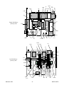
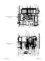
Replaced illustrations - Better parts location
Date
5/16/95
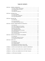
TABLE OF CONTENTS
SECTION 1: GENERAL INFORMATION ...................................................................................... 1
1.01
1.02
1.03
1.04
Notes, Cautions, and Warnings .....................................................................
Important Safety Precautions ........................................................................
Publications ...................................................................................................
Statement Of Warranty ..................................................................................
1
1
6
8
SECTION 2: INTRODUCTION ..................................................................................................... 9
2.01 Scope Of Manual .......................................................................................... 9
2.02 General Service Philosophy .......................................................................... 9
2.03 Service Responsibilities ................................................................................ 9
SECTION 3: DESCRIPTION ....................................................................................................... 11
3.01 Introduction .................................................................................................. 11
3.02 General Description ..................................................................................... 11
3.03 Specifications/Design Features .................................................................... 11
SECTION 4: SERVICE TROUBLESHOOTING DIAGNOSTICS ................................................ 15
4.01 Introduction .................................................................................................
4.02 Periodic Inspection & Procedures ...............................................................
4.03 Common Welding Operating Faults ............................................................
4.04 Circuit Fault Isolation ....................................................................................
4.05 Troubleshooting Guide ................................................................................
4.06 Troubleshooting Specific Problems .............................................................
4.07 Test Procedures ..........................................................................................
4.08 Control/Logic Board (PCB1) Adjustments ...................................................
4.09 Circuit Descriptions .....................................................................................
15
15
15
15
17
18
20
28
31
SECTION 5: REPAIRS & REPLACEMENT PROCEDURES ...................................................... 33
5.01 Introduction ................................................................................................. 33
5.02 Anti-Static Handling Procedures .................................................................. 33
5.03 Disassembly & Replacement ...................................................................... 33
SECTION 6: PARTS LISTS ........................................................................................................ 35
6.01
6.02
6.03
6.04
6.05
Introduction .................................................................................................
Ordering Information ...................................................................................
Complete Systems ......................................................................................
Replacement Parts (Before January 1994) .................................................
Replacement Parts (January 1994 and After) .............................................
35
35
35
36
38
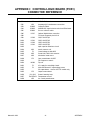
APPENDIX I: CONTROL/LOGIC BOARD (PCB1) CONNECTOR REFERENCE ...................... 41
APPENDIX II: CONTROL/LOGIC BOARD (PCB1) CONNECTOR SIGNALS ............................ 42
APPENDIX III: CONTROL/LOGIC BOARD (PCB1) TEST POINT SIGNALS ............................. 44
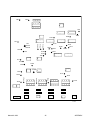
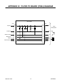
APPENDIX IV: SYSTEM BLOCK DIAGRAM .............................................................................. 46
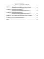
TABLE OF CONTENTS (continued)
APPENDIX V: INTERCONNECTION DIAGRAM
208/230/460V UNIT WITH MECHANICAL INRUSH CIRCUIT.......................... 47
APPENDIX VI: INTERCONNECTION DIAGRAM
380/415V UNIT WITH MECHANICAL INRUSH CIRCUIT ................................ 48
APPENDIX VII: INTERCONNECTION DIAGRAM
460/575V UNIT WITH MECHANICAL INRUSH CIRCUIT ................................ 49
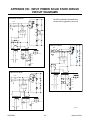
APPENDIX VIII: INPUT POWER SOLID STATE INRUSH CIRCUIT DIAGRAMS ...................... 50
APPENDIX IX: FILTER PC BOARD (PCB4) DIAGRAM ............................................................. 51
INDEX ......................................................................................................................................... 53
SECTION 1:
GENERAL INFORMATION
1.01 Notes, Cautions, and Warnings
Throughout this manual, notes, cautions, and warnings
are used to highlight important information. These highlights are categorized as follows:
NOTE
An operation, procedure, or background information which requires additional emphasis or is helpful in efficient operation of the system.
CAUTION
A procedure which, if not properly followed, may
cause damage to the equipment.
WARNING
A procedure which, if not properly followed, may
cause injury to the operator or others in the operating area.
1.02 Important Safety Precautions
WARNING
Operation and maintenance of arc welding equipment involves potential hazards. Operators and
all others in the operating area should be alerted to
possible hazards, and precautions should be taken
to prevent possible injury.
Read these safety precautions and the entire instruction
manual before operating.
Do not use this power supply to thaw frozen water pipes.
This equipment must be installed, operated, and serviced
by qualified personnel only.
GASES AND FUMES
Gases and fumes produced during arc welding can be
dangerous and hazardous to your health.
Different arc welding processes, electrodes, and fluxes
can produce different fumes, gases and radiation levels.
Consult Material Safety Data Sheets (MSDS’s) and
manufacturer’s instructions for specific technical data and
precautionary measures for all fluxes, electrodes, and
materials used.
Severe discomfort, illness or death can result from fumes,
vapors, heat, or oxygen enrichment or depletion that
welding (or cutting) may produce. Ventilation must be
adequate to remove gases and fumes during operation
as described in ANSI Standard Z49.1.
Use a downdraft table or water table to capture fumes
and gases.
Use an air-supplied respirator if ventilation is not adequate to remove all fumes and gases.
When working in confined spaces provide adequate ventilation or wear an air-supplied respirator if necessary.
Gas leaks in a confined space should be avoided. Leaked
gas in large quantities can change oxygen concentration
dangerously. Do not bring gas cylinders into a confined
space.
When leaving confined space, shut off gas supply at
source to prevent possible accumulation of gases if downstream valves are accidentally opened. Check that area
is safe before re-entering.
Materials containing lead, cadmium, zinc, mercury, beryllium, and similar materials may produce harmful concentrations of toxic fumes when welded or cut. Adequate
local exhaust ventilation must be used, or operators and
others in the operating area must wear an air-supplied
respirator. For beryllium, both must be used.
Metals coated with or containing materials that emit toxic
fumes should not be heated unless coating is removed
from work surface and work area is well ventilated. Wear
an air-supplied respirator if necessary.
Vapors from chlorinated solvents can be decomposed by
the heat of the arc or flame to form phosgene, a highly
toxic gas, and other lung and eye irritating products. The
ultraviolet radiant energy of the arc can also decompose
trichloroethylene and perchloroethylene vapors to form
phosgene. Do not weld or cut where solvent vapors may
be drawn into the welding or cutting atmosphere or where
radiant energy may penetrate to atmospheres containing
even minute amounts of trichloroethylene or perchloroethylene. Solvents, degreasers, and potential sources of
these vapors must be removed from the operating area.
Oil or grease in the presence of oxygen may ignite and
burn violently. Keep cylinders, valves, couplings, regulators, hoses, and other apparatus clean and free from oil
Keep all fumes and gases from the breathing area.
Manual 0-2433
1
GENERAL INFORMATION
and grease. Oxygen cylinders and apparatus should not
be handled with oily hands or gloves. Do not allow an
oxygen stream to contact oily or greasy surfaces.
Recommended Eye Protection for Welding and Cutting
(Based on AWS A6.2-73) is as follows:
Do not use oxygen as a substitute for compressed air.
Welding or
Cutting Operation
NEVER ventilate with oxygen.
Generator engine exhaust must be vented to the outside
air. Carbon monoxide can kill.
Electrode Size
Metal Thickness
or Welding Current
Filter
Shade
Number
Torch soldering
-
2
Torch brazing
-
3 or 4
Oxygen Cutting
ARC RAYS
Light
Under 1 in (25 mm)
3 or 4
Medium
1-6 in (25-150 mm)
4 or 5
Heavy
Over 6 in (150 mm)
5 or 6
Gas welding
Arc rays can injure eyes and burn skin.
Never look at an electric arc without protection. Protect
eyes from exposure to arc. Looking at an arc momentarily with unprotected eyes (particularly a high intensity gas-shielded arc) can cause permanent damage to
vision.
Light
Under 1/8 in (3 mm)
4 or 5
Medium
1/8-1/2 in (3-12 mm)
5 or 6
Heavy
Over 1/2 in (12 mm)
6 or 8
Shielded metal arc welding (stick) electrodes
Use a welding helmet or shield with proper filter (see
chart on page v). Place over face before striking arc.
Light
Under 5/32 in (4 mm)
10
Medium
5/32-1/4 in (4-6.4 mm)
12
Over 1/4 in (6.4 mm)
14
Heavy
Gas metal arc welding (MIG)
Protect filter plate with a clear cover plate.
Non-ferrous base metal
All
Ferrous base metal
Do not use cracked or broken helmet or shield; radiation
can pass through to cause burns.
Gas tungsten arc welding (TIG)
Replace any cracked, broken or loose filter plates immediately. Replace clear cover plate when broken, pitted,
or spattered.
11
All
12
All
12
Atomic hydrogen welding
All
12
Carbon arc welding
All
12
Plasma arc welding
All
12
Light
-
12
Heavy
-
14
Carbon arc air gouging
Flash goggles with side shields must be worn under helmet to protect eyes in case helmet is not in position before arc is struck.
Plasma arc cutting
Wear proper protective clothing. Arc rays can penetrate
lightweight clothing,
Light
Under 300 amps
9
Medium
300-400 amps
12
Welding arc rays can reflect from light-colored surfaces.
Heavy
Over 400 amps
14
Make sure others in the operating area are protected from
arc rays.
ELECTRIC SHOCK
For production welding, use separate room or enclosed
bay. In open areas, surround operation with low reflective non-combustible screens or panels. Make sure that
screen flaps or bay doors are closed before welding. Allow for free air circulation, particularly at floor level.
Electric shock can kill.
Do not contact electrically live parts.
Install equipment according to safety precautions, instruction manual, and all applicable codes.
Provide face shields for all others viewing the weld.
Keep all panels, covers, and guards in place.
Make sure others in the operating area are wearing flash
goggles.
Disconnect all primary power before installing or servicing this equipment.
Insulate operator and others from work and ground.
Replace any cracked or damaged insulating parts.
GENERAL INFORMATION
2
Manual 0-2433
Shut down welding power source before touching electrode, wire drive assembly, welding wire, wire reel, or
any metal parts in contact with the welding wire.
Exposed hot conductors or other bare metal in the welding circuit or in ungrounded, electrically hot equipment
can cause potentially fatal electric shock. Do not contact
a wet surface when welding without suitable protection.
Wear dry insulating gloves and body protection. Keep
body and clothing dry. Never work in damp area without adequate insulation against electrical shock. Stay on
a dry duckboard, or rubber mat when dampness or sweat
cannot be avoided. Sweat, sea water, or moisture between
body and an electrically hot part or grounded metal reduces electrical resistance and could cause potentially
fatal electric shock.
A voltage will exist between the electrode and any conducting object in the work circuit. Examples of conducting objects include, but are not limited to, buildings, electrical tools, work benches, welding power source cases,
workpieces, etc. Never touch electrode to any metal object unless the welding power source is off.
Arc welding equipment must be grounded according to
the National Electrical Code, and the work must be
grounded according to ANSI Z49.1 “Safety in Welding
and Cutting.”
When installing, connect the frames of each unit such as
welding power source, control, work table and water circulator to the building ground. Conductors must be adequate to carry ground currents safely. Equipment made
electrically hot by stray current may cause potentially fatal
electric shock. Do not ground to electrical conduit or to
pipe carrying any gas or flammable liquid such as oil or
fuel.
Check phase requirements before installing. If only threephase power is available, connect single-phase equipment
to only two wires of the three-phase line. Do not connect
the equipment ground lead to the third (live) wire, or the
equipment will become electrically hot - a dangerous condition that may cause potentially fatal electric shock.
Before welding, check ground for continuity. Be sure conductors are touching bare metal of equipment frames at
connections.
If a line cord with a ground lead is provided with the
equipment for connection to a switchbox, connect the
ground lead to the grounded switchbox. If a three-prong
plug is added for connection to a grounded mating receptacle, the ground lead must be connected to the ground
prong only. If the line cord comes with a three-prong
plug, connect to a grounded mating receptacle. Never
remove the ground prong from a plug, or use a plug with
a broken off ground plug.
Manual 0-2433
Fully insulated electrode holders should be used. Do not
use holders with protruding screws.
Fully insulated lock-type connectors should be used to
join welding cable lengths.
Frequently inspect cables for wear, cracks and damage.
Replace those with excessively worn or damaged insulation to avoid potentially fatal electric shock from bared
cable. Cables with damaged areas may be taped to give
resistance equivalent to original cable.
Keep cables dry, free of oil and grease, and protected from
hot metal and sparks.
Terminals and other exposed parts of electrical units
should have insulating covers secured before operation.
Electrode
For equipment with output ON/OFF control (contactor):
Welding power sources for use with gas metal arc welding (GMAW), gas tungsten arc welding (GTAW) and similar processes normally are equipped with devices that
permit ON-OFF control of the welding power output.
When so equipped the electrode wire becomes electrically hot when the power source switch is ON and welding gun switch is closed. Never touch electrode wire or
any conducting object in contact with electrode circuit
unless the welding power source is OFF.
For equipment without output ON/OFF control (no contactor): Welding power sources used with shielded metal
arc welding (SMAW) and similar processes may not be
equipped with welding power output ON-OFF control
devices. With such equipment the electrode is electrically
hot when the power switch is turned ON. Never touch
the electrode unless the welding power source is off.
Safety devices such as interlocks and circuit breakers
should never be disconnected or shunted out.
Before installing, inspecting, or servicing equipment, disconnect primary power and remove line fuses (or lock or
red-tag switches) to prevent accidental electric shock.
Disconnect all cables from welding power source and pull
all 115V line-cord plugs.
Do not open power circuit or change polarity while welding. If it must be disconnected in an emergency, guard
against shock burns and flash from switch arcing.
Always shut off and disconnect all primary power when
leaving equipment unattended.
Primary power disconnect switch must be available near
the welding power source.
3
GENERAL INFORMATION
Flying sparks or falling slag can fly up to 35 ft (10.7 m)
and pass through cracks, along pipes, through windows
or doors, and through wall or floor openings, out of sight
of the operator.
FIRE AND EXPLOSION
Fire and explosion can be caused by hot slag, spatter,
sparks, extreme heat, misuse of compressed gases and
cylinders, and electrical short circuits.
Keep equipment clean and operable, free of oil, grease,
and metallic particles that can cause short circuits in electrical parts.
Remove all combustibles from working area or provide a
fire watch. Avoid paint spray rooms, dip tanks, storage
areas, ventilators. Move work to an area free of combustibles if possible. If work cannot be moved, move combustibles at least 35 ft (10.7 m) away from sparks and
heat or protect against ignition with suitable and snugfitting, fire-resistant covers or shields.
Overloading arc welding equipment beyond rated capacity may overheat cables and cause fire.
Loose cable connections may overheat or flash and cause
fire.
Never strike an arc on a cylinder or other pressure vessel. It creates a brittle area that can cause a violent rupture or lead to rupture under rough handling.
Walls having combustibles on opposite sides should not
be welded on or cut. Walls, ceilings, and floor near work
should be protected by heat-resistant covers or shields.
After work is done, check that area is free of sparks, glowing embers, and flames.
A fire watch with suitable fire extinguishing equipment
must be provided during and after welding or cutting if
combustibles (including building construction) are within
35 ft (10.7 m), if combustibles are further than 35 ft but
may be ignited by flying sparks, or if openings (concealed
or visible) in floors or walls within 35 ft may expose combustibles to sparks.
Burn Prevention - Wear protective clothing including
gauntlet welding gloves, hat, and high safety toe shoes.
Button shirt collar to protect chest and neck, button pocket
flaps, and wear cuffless trousers to avoid entry of sparks
and slag. Wear dark colored, substantial long-sleeve
clothing (particularly for gas-shielded arc). As necessary,
use additional protective clothing such as leather jacket
or sleeves, flame-proof apron, and fire-resistant leggings.
Avoid outer garments of untreated cotton.
Combustibles adjacent to walls, ceilings, roofs, or metal
partitions can be ignited by radiant or conducted heat.
A hot work permit should be obtained before operation
to ensure supervisor’s approval that adequate precautions have been taken.
Wear helmet with safety goggles and glasses with side
shields underneath, appropriate filter lenses or plates
(protected by clear cover glass) for welding or cutting
(and chipping) to protect the eyes from radiant energy
and flying metal. Replace cover glass when broken, pitted, or spattered.
Do not weld or cut an empty container that has held combustibles, or that can produce flammable or toxic vapors
when heated, unless container has first been cleaned as
described in AWS Standard A6.0. This includes a thorough steam or caustic cleaning (or a solvent or water
washing, depending on the combustible’s solubility) followed by purging and inerting with nitrogen or carbon
dioxide, and using protective equipment as recommended in A6.0. Waterfilling just below working level
may substitute for inerting.
Avoid oily or greasy clothing which may be ignited by
sparks.
Do not handle hot metal such as electrode stubs and
workpieces without gloves.
Medical first aid and eye treatment facilities and personnel should be available for each shift unless medical facilities are close by for immediate treatment of flash burns
of the eyes and skin burns.
A container with unknown contents should be cleaned
(see preceding paragraph). Do not depend on smell or
sight to determine if it is safe to weld or cut.
Flammable hair preparations should not be used by persons intending to weld or cut.
Hollow castings or containers must be vented before
welding or cutting to prevent explosion.
Allow work and equipment to cool before handling.
Never weld or cut in potentially explosive atmospheres
containing flammable dust, gas, or liquid vapor (such as
gasoline).
NOISE
Do not mount this equipment over combustible surfaces.
Noise can cause permanent hearing loss.
Wear proper protective ear muffs or plugs.
GENERAL INFORMATION
4
Manual 0-2433
Make sure others in the operating area are protected from
noise.
HIGH PRESSURE GAS CYLINDERS
Comply with the precautions in this manual and those
detailed in CGA Standard P-1, SAFE HANDLING OF
COMPRESSED GASES IN CYLINDERS.
Pressure Regulators:
Regulator relief valve is designed to protect only the regulator from overpressure and not intended to protect any
downstream equipment. Provide such protection with
one or more relief devices.
Never connect a regulator to a cylinder containing gas
other than that for which the regulator was designed.
Remove faulty regulator from service immediately for
repair (first close cylinder valve) if gas leaks externally, if
delivery pressure continues to rise with downstream
valve closed, or if gauge pointer does not move off stop
pin when pressurized, nor returns to stop pin after pressure release.
Do not attempt to repair faulty regulators. Send to
manufacturer’s authorized repair center where special
techniques and tools are used by trained personnel.
Cylinders must be handled carefully to prevent leaks and
damage to walls, valves, or safety devices.
Contact with electrical circuits including third rails, electrical wires, or welding circuits can product short circuit
arcs that may lead to a serious accident.
ICC or DOT markings must be on each cylinder as an
assurance of safety when the cylinder is properly handled.
Use only cylinders with name of gas clearly marked on
them; do not rely on color to identify gas content. Notify
supplier if unmarked. Never deface or alter name, number or other markings on a cylinder.
Keep valves closed on empty cylinders, replace caps securely, mark MT, keep separate from full cylinders and
return promptly.
Never use a cylinder or contents for other than intended
use. Never use as a support or roller.
Locate or secure cylinders so they cannot be knocked over.
Keep cylinders clear of passageways and work areas
where they may be struck.
To transport cylinders with a crane, use a secure support
such as a platform or cradle. Do not lift cylinders by
valves or caps, or by chains, slings, or magnets.
Manual 0-2433
Do not expose cylinders to excessive heat, sparks, slag,
or flame which may cause rupture. Do not allow contents to exceed 1300°F. Cool with water spray where such
exposure exists.
Protect cylinders and valves from bumps, falls, falling
objects, and weather. Replace caps securely when moving cylinders.
Do not use hammer or wrench to open a cylinder lock
valve which cannot be opened by hand. Notify supplier.
Never mix gases in a cylinder.
Never refill any cylinder.
Do not modify or exchange cylinder fittings.
Hose
Never use hose unless appropriate for specified gas. General hose identification is: red for fuel gas, green for oxygen, and black for inert gases.
Use ferrules or clamps designed for hose (not ordinary
wire or other substitute) as a binding to connect hoses to
fittings.
Do not use copper tubing splices. Use only standard brass
fittings to splice hose.
Avoid long runs to prevent kinks and abuse. Coil excess
hose to prevent kinks and tangles. Suspend hose off
ground to protect from damage. Protect hose from damage by sharp edges, sparks, slag, excessive heat, and open
flame.
Examine hose regularly for leaks, wear, and loose connections. Immerse pressured hose in soapy water;
bubbles indicate leaks.
Repair leaky or worn hose by cutting area out and splicing. Do not tape.
Proper Connections
Keep cylinder valve outlet free of impurities which may
clog orifices and damage seats before connecting regulator. Except for hydrogen, crack valve momentarily and
point outlet away from people and sources of ignition.
Wipe clean with a lintless cloth.
Match regulator to cylinder. Before connecting, check that
regulator label and cylinder marking area match and that
regulator inlet and cylinder outlet match. Never connect
a regulator designed for one type of gas to a cylinder containing another gas.
When assembling threaded connections, clean and
smooth seats where necessary before tightening. If connection leaks, disassemble, clean, and retighten using
properly fitting wrench.
5
GENERAL INFORMATION
Use a CGA adapter (available from supplier) between
cylinder and regulator, if required. Use two wrenches to
tighten adapter marked RIGHT and LEFT HAND
threads.
2. NIOSH, SAFETY AND HEALTH IN ARC WELDING
AND GAS WELDING AND CUTTING, obtainable from
the Superintendent of Documents, U.S. Government
Printing Office, Washington, D.C. 20402
Regulator outlet (or hose) connections may be identified
by right hand threads for oxygen and left hand threads
(with grooved hex on nut or shank) for fuel gas.
3. OSHA, SAFETY AND HEALTH STANDARDS, 29CFR
1910, obtainable from the Superintendent of Documents,
U.S. Government Printing Office, Washington, D.C. 20402
Pressurizing Steps
4. ANSI Standard Z87.1, SAFE PRACTICES FOR OCCUPATION AND EDUCATIONAL EYE AND FACE
PROTECTION, obtainable from American National Standards Institute, 1430 Broadway, New York, NY 10018
Drain regulator of residual gas through suitable vent before opening cylinder (or manifold valve) by turning adjusting screw clockwise. Draining prevents excessive
compression heat at high pressure seat by allowing seat
to open on pressurization. Leave adjusting screw engaged
slightly on single-stage regulators.
5. ANSI Standard Z41.1, STANDARD FOR MEN’S
SAFETY-TOE FOOTWEAR, obtainable from the American National Standards Institute, 1430 Broadway, New
York, NY 10018
Do not stand in front of regulator while opening cylinder
valve.
6. ANSI Standard Z49.2, FIRE PREVENTION IN THE
USE OF CUTTING AND WELDING PROCESSES, obtainable from American National Standards Institute,
1430 Broadway, New York, NY 10018
Open cylinder valve slowly so that regulator pressure
increases slowly. When gauge is pressurized (gauge
reaches regulator maximum) open cylinder valve fully
to seal stem against possible leak when using oxygen and
inert gases. For fuel gas, open less than one turn to permit quick emergency shutoff.
7. AWS Standard A6.0, WELDING AND CUTTING
CONTAINERS WHICH HAVE HELD COMBUSTIBLES,
obtainable from American Welding Society, 550 N.W.
LeJeune Rd, Miami, FL 33126
Use pressure charts (available from supplier) for safe and
efficient, recommended pressure settings on regulators.
8. NFPA Standard 51, OXYGEN-FUEL GAS SYSTEMS
FOR WELDING, CUTTING AND ALLIED PROCESSES,
obtainable from the National Fire Protection Association,
Batterymarch Park, Quincy, MA 02269
Check for leaks on first pressurization and regularly thereafter. Brush with soapy solution (one capful of liquid
detergent per gallon of water); bubbles indicate leak
Clean off soapy water after test; dried soap is combustible.
9. NFPA Standard 70, NATIONAL ELECTRICAL CODE,
obtainable from the National Fire Protection Association,
Batterymarch Park, Quincy, MA 02269
Remove leaky or defective equipment immediately for
repair.
10. NFPA Standard 51B, CUTTING AND WELDING
PROCESSES, obtainable from the National Fire Protection Association, Batterymarch Park, Quincy, MA 02269
Close gas supply at source and drain gas when leaving
equipment unattended.
11. CGA Pamphlet P-1, SAFE HANDLING OF COMPRESSED GASES IN CYLINDERS, obtainable from the
Compressed Gas Association, 1235 Jefferson Davis Highway, Suite 501, Arlington, VA 22202
Do not use rope staging support for welding or cutting
operation; rope may burn.
Electronic Life Support Devices (Pacemakers)
12. CSA Standard W117.2, CODE FOR SAFETY IN
WELDING AND CUTTING, obtainable from the Canadian Standards Association, Standards Sales, 178 Rexdale
Boulevard, Rexdale, Ontario, Canada M9W 1R3
Magnetic fields from high currents can affect pacemaker
operation. Persons wearing electronic life support equipment (pacemakers) should consult with doctor before
going near arc welding, gouging, or spot welding operations.
13. NWSA booklet, WELDING SAFETY BIBLIOGRAPHY
obtainable from the National Welding Supply Association, 1900 Arch Street, Philadelphia, PA 19103
1.03 Publications
Refer to the following standards or their latest revisions
for more information:
14. American Welding Society Standard AWSF4.1, RECOMMENDED SAFE PRACTICES FOR THE PREPARATION FOR WELDING AND CUTTING OF CONTAINERS AND PIPING THAT HAVE HELD HAZARDOUS
SUBSTANCES, obtainable from the American Welding
Society, 550 N.W. LeJeune Rd, Miami, FL 33126
1. ANSI Standard Z49.1, SAFETY IN WELDING AND
CUTTING, obtainable from the American Welding Society, 550 N.W. LeJeune Rd, Miami, FL 33126
GENERAL INFORMATION
6
Manual 0-2433
15. ANSI Standard Z88.2, PRACTICE FOR RESPIRATORY PROTECTION, obtainable from American National Standards Institute, 1430 Broadway, New York, NY
10018
Manual 0-2433
7
GENERAL INFORMATION
1.04 Statement Of Warranty
LIMITED WARRANTY: Thermal Dynamics Corporation (hereinafter “Thermal”) warrants that its products will be
free of defects in workmanship or material. Should any failure to conform to this warranty appear within the time
period applicable to the Thermal products as stated below, Thermal shall, upon notification thereof and substantiation
that the product has been stored, installed, operated, and maintained in accordance with Thermal’s specifications,
instructions, recommendations and recognized standard industry practice, and not subject to misuse, repair, neglect,
alteration, or accident, correct such defects by suitable repair or replacement, at Thermal’s sole option, of any components or parts of the product determined by Thermal to be defective.
THIS WARRANTY IS EXCLUSIVE AND IS IN LIEU OF ANY WARRANTY OF MERCHANTABILITY OR FITNESS FOR A PARTICULAR PURPOSE.
LIMITATION OF LIABILITY: Thermal shall not under any circumstances be liable for special or consequential
damages, such as, but not limited to, damage or loss of purchased or replacement goods, or claims of customers of
distributor (hereinafter “Purchaser”) for service interruption. The remedies of the Purchaser set forth herein are exclusive and the liability of Thermal with respect to any contract, or anything done in connection therewith such as the
performance or breach thereof, or from the manufacture, sale, delivery, resale, or use of any goods covered by or
furnished by Thermal whether arising out of contract, negligence, strict tort, or under any warranty, or otherwise, shall
not, except as expressly provided herein, exceed the price of the goods upon which such liability is based.
THIS WARRANTY BECOMES INVALID IF REPLACEMENT PARTS OR ACCESSORIES ARE USED WHICH
MAY IMPAIR THE SAFETY OR PERFORMANCE OF ANY THERMAL PRODUCT.
THIS WARRANTY IS INVALID IF THE PRODUCT IS SOLD BY NON-AUTHORIZED PERSONS.
The limited warranty periods for Thermal products shall be as follows: A maximum of three (3) years from date of sale
to an authorized distributor and a maximum of two (2) years from date of sale by such distributor to the Purchaser, and
with the following further limitations on such two (2) year period:
PAK UNITS, POWER SUPPLIES
PARTS
LABOR
MAIN POWER MAGNETICS ....................................................... 2 YEARS ..................... 1 YEAR
ORIGINAL MAIN POWER RECTIFIER ...................................... 2 YEARS ..................... 1 YEAR
CONTROL PC BOARD .................................................................. 2 YEARS ..................... 1 YEAR
ALL OTHER CIRCUITS AND COMPONENTS .......................... 1 YEAR ...................... 1 YEAR
INCLUDING, BUT NOT LIMITED TO, STARTING
CIRCUIT, CONTACTORS, RELAYS, SOLENOIDS, PUMPS,
POWER SWITCHING SEMI-CONDUCTORS
CONSOLES, CONTROL EQUIPMENT, HEAT ........................... 1 YEAR ...................... 1 YEAR
EXCHANGES, AND ACCESSORY EQUIPMENT
TORCH AND LEADS ..................................................................... 180 DAYS .................. 180 DAYS
REPAIR/REPLACEMENT PARTS ................................................. 90 DAYS .................... 90 DAYS
Warranty repairs or replacement claims under this limited warranty must be submitted by an authorized Thermal Arc®
repair facility within thirty (30) days of the repair. Authorized Thermal Arc® repair facilities are authorized distributors
and authorized Thermal Arc® Service Centers. No transportation costs of any kind will be paid under this warranty.
Transportation charges to send products to an authorized warranty repair facility shall be the responsibility of the
customer. All returned goods shall be at the customer's risk and expense. This warranty supersedes all previous
Thermal warranties.
Thermal Arc® is a Registered Trademark of Thermal Dynamics.
Effective January 18, 1991
GENERAL INFORMATION
8
Manual 0-2433
SECTION 2:
INTRODUCTION
2.01 Scope Of Manual
This Manual provides Service Instructions for Thermal
Dynamics Model 300GTS Inverter Arc Welder.
Refer to Operating Manual (0-2425) for individual operating procedures. Information in this edition is therefore
particularly applicable to the Troubleshooting and Repair
of the equipment, and is intended for use by properlytrained Service Technicians familiar with this equipment.
2.03 Service Responsibilities
The Service Technician should be familiar with the equipment and its capabilities. He should be prepared to recommend arrangements of components which will provide the most efficient layout, utilizing the equipment to
its best possible advantage.
Maintenance work should be accomplished in a timely
manner. If problems are encountered, or the equipment
does not function as specified, contact Technical Services
Department at West Lebanon for assistance.
Read this Manual and the Operating Manual, 0-2425,
thoroughly. A complete understanding of the capabilities and functions of the equipment will assure obtaining
the performance for which it was designed.
2.02 General Service Philosophy
Several key points are essential to properly support the
application and operation of this equipment.
A. Application
The equipment should satisfy the customer’s requirements as supplied and as described in Section 3 of this
manual. Be sure to confirm that the equipment is capable
of the application desired.
B. Modifications
No physical or electrical modifications other than selection of standard options and Accessories are to be made
to this equipment.
C. Customer/Operator Responsibilities
It is the customer/operators’ responsibility to maintain
the equipment and peripheral Accessories provided by
Thermal Dynamics in good operating order in accordance
with the procedures outlined in the Operating Manual,
and to protect the equipment from accidental or malicious damage.
D. Repair Restrictions
The electronics consists of Printed Circuit Board Assemblies which must be carefully handled, and must be replaced as units. No replacement of printed circuit solder-mounted components is allowed except as noted in
this manual.
Printed Circuit Board Assemblies to be returned must be
properly packaged in protective material and returned
intact per normal procedures.
Manual 0-2433
9
INTRODUCTION
INTRODUCTION
10
Manual 0-2433
SECTION 3:
DESCRIPTION
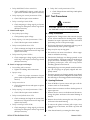
4.
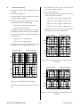
NOTE
The ARC control may be adjusted while welding.
The ARC control provides a variable selection of short
circuit amperage to suit individual welding situations
when operating in the STICK (SMAW) mode. Rotating the control clockwise causes amperage to increase
as a short circuit condition is approached.
3.01 Introduction
The information in this Section has two purposes: To familiarize the Service Technician with the capabilities and
limitations of the equipment, and to provide him with an
overall understanding which will allow him, in turn, to
properly train the customer’s operating personnel.
When the control is set at 100, short circuit amperage
is considerably higher than normal welding amperage. This provides extra amperage for arc starting in
out-of-position welds as well as momentary over
amperage necessary for certain electrode types.
3.02 General Description
The Thermal Arc™ 300GTS is a three-phase or singlephase (if derated) DC arc welding power source with
Constant Current (CC) output characteristics. The unit is
equipped with a gas control valve, lift arc starter, and
high-frequency arc starter for use with Gas Tungsten Arc
Welding (GTAW). This unit is designed for use with
Shielded Metal Arc Welding (SMAW), Gas Tungsten Arc
Welding - Lift Start (GTAW) and Gas Tungsten Arc Welding - Pulsed (GTAW-P) processes. A digital amperage/
voltage meter is optional.
When the control is set at 0 (zero), short circuit amperage above normal welding amperage is minimal.
When the control is set at 50, short circuit amperage
is approximately half that of the 100 position, but still
higher than normal welding amperage. The 50 position provides a moderate amperage increase for arc
starting necessary for certain type of electrodes and
applications.
Select a setting best suited for the application and
electrode type.
3.03 Specifications/Design Features
A. Front Panel Controls/Indicators
5.
The AC POWER indicator on the front panel comes
on when the PRIMARY POWER switch is in ON position, indicating that the unit is energized.
2. WARNING Indicator
The WARNING indicator located on the front panel
will turn ON if the unit detects one of the following
conditions:
Input voltage too low
•
Thermal overload
Process Selector Switch
The process selector toggle switch allows the operator to select the type of process to be used. There are
three settings for the switch. When to the left it selects the STICK welding (SMAW) process; center selects the LIFT TIG welding (GTAW) process; to the
right selects the HF TIG welding (GTAW) process.
1. AC POWER Indicator
•
ARC Control
a. STICK Welding (SMAW)
STICK
The unit provides weld output characteristics specifically designed for the Shielded Metal Arc Welding (SMAW) process. The ARC control is active.
b. HF TIG (GTAW with High Frequency Start)
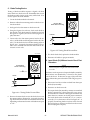
3. AMPERAGE Control
HF TIG
NOTE
In this position, the unit provides weld output for
the gas tungsten arc welding (GTAW) process.
High frequency will be present from the time the
contactor is closed until a welding arc is established. Once an arc is established, high frequency
is no longer present. High frequency is present
any time the arc is broken to aid in restarting the
arc as long as the contactor is energized. When
the process selector switch is in this position, the
POST FLOW control will function and the ARC
control will not function.
The AMPERAGE control may be adjusted while
welding.
The AMPERAGE control selects the desired amperage within the entire range of the welding power
source. Rotating the control clockwise increases the
amperage output. The scale surrounding the AMPERAGE control represents the approximate amperage (A) value.
Manual 0-2433
11
DESCRIPTION
c. LIFT TIG (GTAW without High Frequency)
b. ON Position
LIFT
TIG
The unit provides weld output for the gas tungsten arc welding (GTAW) process. High frequency
will not be present. POST FLOW control will function. The ARC and HOT START controls will not
function. The unit will provide a low open circuit
voltage and approximately 15 amps (for 1.0 ms)
to the tungsten electrode when touched to the
work and lifted away from surface. After the
welding arc becomes established, the output current will be regulated at determined current level.
6.
Remote contactor control not used. Open circuit
voltage will be available whenever the PRIMARY
POWER switch is in ON position.
8.
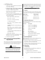
POST FLOW time can be adjusted from 1-50 seconds.
Rotating the control clockwise increases post flow
time.
This switch determines whether the amperage/voltage is adjusted by the front panel AMPERAGE control or by a remote control device.
PANEL Position
POST FLOW Control
The POST FLOW control sets the length of time gas
flows after the arc is extinguished. Post flow time
begins when the arc is broken and the contactor
opens. When post flow time ends, the gas valve
closes, shutting off shielding gas flow to the torch.
AMPERAGE Switch
a.
ON
NOTE
The POST FLOW control and gas valve only work
if the process selector switch is in one of the gas
tungsten arc welding positions, the OUTPUT
CONTACTOR switch is in REMOTE position,
and a remote control is connected to the REMOTE
14 receptacle.
PANEL
If remote control function is not desired, place this
switch in PANEL position.
14
b. REMOTE 14 Position REMOTE
9.
The PRE FLOW control only works if the process selector switch is in HF TIG position, the OUTPUT
CONTACTOR switch is in REMOTE position and a
remote control is connected to the REMOTE 14 receptacle.
For remote amperage control, place the AMPERAGE switch in REMOTE 14 position.
Remote control is a percentage of the value set by
the front panel AMPERAGE control. For example,
if the AMPERAGE control is set at half maximum
output, the maximum output available from the
remote control will be half the welding power
source maximum output.
7.
PRE FLOW Control
The PRE FLOW time can be adjusted from 0.5 to 15
seconds. The welding arc and high frequency will
not become established until the PRE FLOW control
completes timing. Rotating the control clockwise increases the PRE FLOW time.
OUTPUT CONTACTOR Switch
NOTE
The HOT START control only works if the process
selector switch is in HF TIG position, the OUTPUT
CONTACTOR switch is in REMOTE position and a
remote control is connected to the REMOTE 14 receptacle.
Although the term CONTACTOR is used the output is not switched on or off by a physical contactor; rather, the unit uses solid-state output control.
The switch has two functions:
14
a. REMOTE 14 PositionREMOTE
Contactor connections are made to the REMOTE
14 receptacle. Open circuit voltage will be present
at the weld output receptacles whenever the torch
switch or remote device is closed.
DESCRIPTION
12
Manual 0-2433
10.
HOT START Control
2.
The HOT START time is approximately 0.1 seconds
and the HOT START current value is adjusted from 0
to 100% over the determined weld current set at
AMPERAGE control. Rotating the control clockwise
increases HOT START current.
Available for the following input power:
208 VAC (±10%), 50/60 Hz, Single or Three-Phase
230 VAC (±10%), 50/60 Hz, Single or Three-Phase
380 VAC (±10%), 50/60 Hz, Three-Phase
Example: Weld current set at AMPERAGE control is 100 amps and HOT START is set at 50%.
The arc will initiate at 150 amps for 0.1 seconds
and then resume at 100 amps.
The process selector switch allows the operator to select the STICK welding (SMAW) process, the LIFT
TIG (GTAW) process without high frequency, or the
HF TIG (GTAW) process with high frequency start.
11.
400 VAC (±10%), 50/60 Hz, Three-Phase
415 VAC (±10%), 50/60 Hz, Three-Phase
460 VAC (±10%), 50/60 Hz, Single or Three-Phase
575 VAC (±10%), 50/60 Hz, Three-Phase
3.
Rated Load Output
The following data is at 60% duty cycle:
Optional Digital AMPERAGE/VOLTAGE
Meter and Switch
Single-Phase:
The LED AMPERAGE/VOLTAGE meter displays either an amperage (A) or voltage (V) value. The selected (preview) amperage value is displayed when
welding is not taking place.
Amperes
Volts
Duty Cycle
Range (Min-Max)
Amperes
Volts
Maximum OCV
The meter is not intended for exact amperage or voltage measurements. The amperage display indicates
amperage output of the welding power source and
is driven by circuitry on control board PC1. The voltage sensing circuitry is internally connected to the
welding power source output terminals. The voltage display indicates the voltage at the weld output
terminals, but does not necessarily indicate the actual voltage at the welding arc (due to cable resistance, poor connections, etc.).
210
28
60%
5-260
10-30
70
Three-Phase:
Amperes
Volts
Duty Cycle
Range (Min-Max)
Amperes
Volts
Maximum OCV
C. PRIMARY POWER Switch (Rear Panel)
The PRIMARY POWER switch (circuit breaker) energizes the welding power source when placed in the
ON position. Placing the PRIMARY POWER switch
in OFF position shuts down the welding power source
and turns off the AC POWER indicator.
Input Power
4.
300
32
60%
5-375
10-36
70
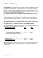
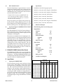
Load/No Load Outputs
D. Input Power
1.
Input power SMART-LINK
Unit incorporates a Inrush circuit and input voltage
sensing circuit. When MCB1 is turned on the Inrush
circuit provides a precharging of the input capacitors. MC-1 will close after the input capacitors have
charged to full operating voltage (approximately 5
seconds). During precharge the control/logic board
is sensing the input voltage and configuring the input power circuit and control transformer to match
the input voltage. The Power Supply is configured
to the highest input voltage when MCB1 is in the OFF
position.
Manual 0-2433
208 VAC 1-Phase
208 VAC 3-Phase
230 VAC 1-Phase
230 VAC 3-Phase
380 VAC 3-Phase
400 VAC 3-Phase
415 VAC 3-Phase
460 VAC 1-Phase
460 VAC 3-Phase
575 VAC 3-Phase
13
Output At
No Load Output
Rated Load
Amps KVA KW Amps KVA KW
48
10
7
2.5 0.5 0.3
39
14
11
1.5 0.5 0.3
43
10
7
2
0.5 0.3
35
14
11
1
0.5 0.3
21
14
11
1
0.5 0.3
18
14
11
1
0.5 0.3
19
14
11
0.5 0.5 0.3
21
10
7
1
0.5 0.3
18
14
11
0.5 0.5 0.3
14
14
11
0.5 0.5 0.3
DESCRIPTION
5.
Duty Cycle
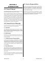
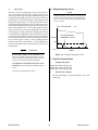
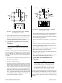
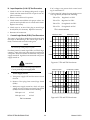
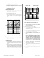
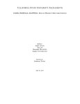
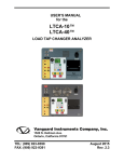
E. Voltage/Amperage Curve
The duty cycle of a welding power source is the percentage of a ten minute period that a welding power source
can be operated at a given output without causing overheating and damaging of the unit. This unit is rated at 60
percent duty cycle when operated at 300 amperes from
three-phase input power, or when operated at 210 amperes from single-phase input power. If the unit is operated from three-phase input power, the unit can be operated at 300 amperes for six consecutive minutes, but it
must operate at no load for the remaining four minutes
to allow proper cooling. When the welding power source
is operated from single-phase input power, the unit can
be operated at 210 amperes for six consecutive minutes,
but it must operate at no load for the remaining four minutes to allow proper cooling. If the welding amperes
decrease, the duty cycle increases. If the welding amperes are increased beyond rated output, the duty cycle
will decrease.
NOTE
Voltage/Amperage curve shows the voltage and
amperage output capabilities of the welding power
source. Curves of other settings will fall between
the curve shown.
OCV Less than 80V
Arc Characteristics
"CURRENT" Control
VOLTS
19V
5
CONTINUAL EXCEEDING OF DUTY CYCLE
RATINGS can cause damage to the welding power
source.
Do not exceed indicated duty cycles.
150
A-00032
CAUTIONS
EXCEEDING DUTY CYCLE RATINGS will
cause the thermal overload protection circuit to
become energized and shut down output until the
unit cools to normal operating temperature.
C.C.
AMPS
375 410
Figure 3-A Voltage/Amperage Curve
F. Physical Characteristics
1.
Weight with Cable
Model 230/46083.8 lb (38.1 kg)
Model 380/41576.6 lb (34.8 kg)
Model 460/57579.0 lb (35.9 kg)
2.
Dimensions All Units
20" (510 mm) High x 12" (305 mm) Wide x 18.5" (470
mm) Long
DESCRIPTION
14
Manual 0-2433
SECTION 4:
SERVICE
TROUBLESHOOTING
DIAGNOSTICS
4.01 Introduction
This Section provides service diagnostics for the Model
300GTS Inverter Arc Welding System, allowing the Technician to islolate any faulty Subassemblies. Refer to Section 5, Repairs & Replacement Procedures, for parts replacement instructions.
CAUTION
Do not blow air into the power supply during cleaning. Blowing air into the unit can cause metal particles to interfere with sensitive electrical components and cause damage to the unit.
4.03 Common Welding Operating
Faults
The following are some common operating faults during
the welding operation:
A. Power
Main power not connected
Under no circumstances are field repairs to be attempted
on Printed Circuit Boards or other Subassemblies of this
unit. Evidence of unauthorized repairs will void the factory warranty.
Main power not turned on
Main ON/OFF switch to OFF
B. Poor Weld
Wrong electrode used
WARNINGS
Electrode not properly prepared
Disconnect primary power at the source before disassembling the power supply.
Frequently review the Important Safety Precautions (page 1). Be sure the operator is equipped with
proper gloves, clothing, eye and ear protection.
Make sure no part of the operator’s body comes into
contact with the workpiece while the unit is activated.
Incorrect welding amperage setting
Speed to fast or slow
Incorrect switch settings for operation
Poor weld output connection(s)
C. Remote Operation
Incorrect switch settings
4.02 Periodic Inspection &
Procedures
Remote not connected
4.04 Circuit Fault Isolation
This subsection describes inspection procedures which
should be performed at periodic intervals as required.
NOTE
Before beginning troubleshooting visually inspect
the internal components for signs of over heating,
fractures and damage.
The only routine maintenance required for the power supply is a thorough cleaning and inspection, with the frequency depending on the usage and the operating environment.
CAUTION
To clean the unit, open the enclosure (refer to Section 4.07B, Opening Enclosure) and use a vacuum cleaner to remove any accumulated dirt and dust. The unit should
also be wiped clean. If necessary, solvents that are recommended for cleaning electrical apparatus may be used.
Sparks from the welding process can cause damage to coated, painted, and other surfaces such as
glass, plastic and metal.
This section is to help isolate the defect circuit before
troubleshooting, identify symptoms, and test the unit for
proper operation. Follow the instructions as given to identify the possible symptom(s) and the defective circuit.
After repairs are complete then run the following tests
again to verify that the unit is fully operational.
Manual 0-2433
15
SERVICE TROUBLESHOOTING
11. Place the power supply ON/OFF circuit breaker
(MCB) on back of unit to the ON position and note
the following:
A. Initial Setup Conditions
Set the front panel controls per the following:
1. Set Process Selector switch to STICK mode
a. MC2 will close three seconds after turning on
MCB.
2. Set OUTPUT CONTACTOR selector to REMOTE
14 position
b. MCB1 will close five seconds after turning on
MCB.
3. Set AMPERAGE selector to PANEL position
NOTE
4. Amperage (A) control fully counterclockwise
(minimum)
Newer units have solid state inrush circuit where
MC1 is part of the Input Diode Module (D1).
5. ARC control fully counterclockwise (minimum)
12. Place OUTPUT CONTACTOR selector to ON
position. The meter will indicate approximately
60vdc open circuit.
6. No connections to the remote receptacle(s)
B. SMART-LINK Test
1. Place METER selector on optional Digital Meter
to the ‘V’ position to indicate volts. If the optional
Digital Meter is not installed then connect a digital voltmeter between the positive (+) and negative (-) output terminals of the unit. Set the digital voltmeter to indicate VDC.
2. Connect the unit to 460 volt, 3 phase input voltage. Connect the wires as follows:
a. Red to Line 1
13. Place OUTPUT CONTACTOR selector to Remote14 position.
14. Turn off the power supply ON/OFF circuit
breaker (MCB).
This completes the SMART-LINK test. If any step does
not function as noted then the SMART-LINK Circuit is
defective. Note the symptom and proceed to Section 4.05,
Troubleshooting Guide.
C. Output Load Test
b. White to Line 2
1. Place OUTPUT CONTACTOR selector to Remote14 position.
c. Black to Line 3
d. Green to earth ground.
a. Connect the output negative and positive
posts in a dead short condition.
3. Turn on primary power at the source.
b. Place METER selector on optional Digital
Meter to the ‘A’ position to indicate amperage. If the optional Digital Meter is not installed then use a clamp on amperage meter
around the output loop between the positive
(+) and negative (-) output terminals of the
unit.
4. Place the power supply ON/OFF circuit breaker
(MCB) on back of unit to the ON position. Five
seconds later MC1 will close.
NOTE
Newer units have solid state inrush circuit where
MC1 is part of the Input Diode Module (D1).
2. Place OUTPUT CONTACTOR selector to ON position. The meter will indicate approximately 5
amperes.
5. Place OUTPUT CONTACTOR selector to ON position. The meter will indicate approximately
60vdc open circuit.
3. Slowly turn the Amperage (A) control clockwise
to maximim The meter should increase slowly to
a maximum of approximately 375 amperes and
then decrease back to 5 amperes as the Amperage (A) control is turned counterclockwise.
6. Place OUTPUT CONTACTOR selector to Remote
14 position.
7. Turn off the power supply ON/OFF circuit
breaker (MCB).
4. Place OUTPUT CONTACTOR selector to Remote
14 position.
8. Turn off primary power at the source.
9. Reconnect the unit to 230 volt ,3 phase input voltage.
10. Turn on primary power at the source.
SERVICE TROUBLESHOOTING
5. Remove short circuit condition.
This completes the Output Load Test. If any step does
not function as noted then the Output Circuit is defective. Note the symptom and proceed to Section 4.05,
Troubleshooting Guide.
16
Manual 0-2433
8. Place METER selector on optional Digital Meter
to the ‘A’ position to indicate amperage. If the
optional Digital Meter is not installed then use a
clamp on amperage meter around the output loop
between the positive (+) and negative (-) output
terminals of the unit. Meter will indicate approximately 17 to 28 amperes.
D. Arc Control Test
1. Place OUTPUT CONTACTOR selector to Remote14 position.
a. Connect the output negative and positive
posts in a dead short condition.
b. Place METER selector on optional Digital
Meter to the ‘A’ position to indicate amperage. If the optional Digital Meter is not installed then use a clamp on amperage meter
around the output loop between the positive
(+) and negative (-) output terminals of the
unit.
2. Place OUTPUT CONTACTOR selector to ON position.
3. Adjust Amperage (A) control until meter indicates
100 amperes.
9. Place OUTPUT CONTACTOR selector to REMOTE 14 position.
10. Remove short circuit condition.
This completes the LIFT TIG Test. If any step does not
function as noted then the LIFT TIG Circuit is defective.
Note the symptom and proceed to Section 4.05, Troubleshooting Guide.
F. HF (High Frequency) TIG Circuit Test
1. Set Process Selector switch to HF TIG mode.
4. Turn ARC control clockwise to maximum setting.
Meter will indicate approximately 245 amperess.
2. Place OUTPUT CONTACTOR selector to REMOTE 14 position.
5. Turn ARC control back to minimum.
3. Close remote switch. After PRE-FLOW time HF
circuit will turn ON (arc at points).
6. Place OUTPUT CONTACTOR selector to Remote14 position..
4. Open remote switch. HF circuit turns OFF.
7. Remove short circuit condition.
5. Connect the output negative and positive posts
in a dead short condition.
This completes the Arc Control Test. If any step does
not function as noted then the Arc Control Circuit is defective. Note the symptom and proceed to Section 4.05,
Troubleshooting Guide.
6. Close remote switch. HF circuit should not turn
ON.
7. Open remote switch.
E. LIFT TIG Circuit Test
1. Set Process Selector switch to LIFT TIG mode.
2. Place OUTPUT CONTACTOR selector to REMOTE 14 position.
3. Place METER selector on optional Digital Meter
to the ‘V’ position to indicate volts. If the optional
Digital Meter is not installed then connect a digital voltmeter between the positive (+) and negative (-) output terminals of the unit. Set the digital voltmeter to indicate VDC.
4. Place OUTPUT CONTACTOR selector to ON position. Meter will indicate approximately 12 to
14 volts
8. Remove short circuit condition.
This completes the HF TIG Test. If any step does not function as noted then the HF TIG Circuit is defective. Note
the symptom and proceed to Section 4.05, Troubleshooting Guide.
4.05 Troubleshooting Guide
A. Troubleshooting and Repair
Troubleshooting and repairing this unit is a process which
should be undertaken only by those familiar with high
voltage/high power electronic equipment.
WARNING
5. Place OUTPUT CONTACTOR selector to REMOTE 14 position.
There are extremely dangerous voltage and power
levels present inside this unit. Do not attempt to
diagnose or repair unless you have had training in
power electronics measurement and troubleshooting techniques.
6. Connect the output negative and positive posts
in a dead short condition.
7. Place OUTPUT CONTACTOR selector to ON position. Meter will indicate approximately 1 volt.
Manual 0-2433
17
SERVICE TROUBLESHOOTING
B. Advanced Troubleshooting
NOTE
4.06 Troubleshooting Specific
Problems
Troubleshooting Preparation
1. Set PROCESS selector switch to the STICK mode.
For basic troubleshooting and parts replacement
procedures refer to Model 300GTS Inverter Arc
Welder Operating Manual 0-2425.
2. Set Contactor selector switch to REMOTE 14 position.
3. Set AMPERAGE selector switch to PANEL position.
The advanced troubleshooting covered in this Service
Manual requires disassembly of the unit and live measurements. It is helpful for solving many of the common
problems that can arise with the Model 300GTS Inverter
Arc Welding System.
4. Disconnect all remote devices.
5. Connect to input voltage (check data tag on back
of power supply for proper input voltage required).
If major complex subassemblies are faulty, the unit must
be returned to an authorized service center for repair.
NOTE
Specific test procedures and reference tables have been
grouped together, and are referenced by the troubleshooting guide. Use the tables, diagrams, and test procedures
in conjunction with the troubleshooting guide to perform
the tests and repairs.
Before beginning make sure primary power is turned off
and disconnected from the wall outlet. Wait two minutes before opening the enclosure to allow the primary
capacitors to discharge.
Operate power supply on ALL input voltages as
noted on nameplate when testing power supply.
6. Close wall disconnect switch or circuit breaker.
7. Turn power supply ON/OFF circuit breaker
(MCB) to ON.
A. Power supply ON/OFF circuit breaker (MCB) trips
when turned ON; OUTPUT CONTACTOR
selector in REMOTE 14 position
Before beginning troubleshooting visually inspect the
internal components for signs of over heating, fractures
and damage.
1. Input voltage over rated limit
The guide has two sections as follows:
2. Shorted or burned MC2 contactor
a. Connect to proper line voltage.
Section 4.06 - Troubleshooting Specific Problems
a. Check MC2 contacts for shorts and replace if
necessary.
Section 4.07 - Test Procedures
b. Check MC2 actuator assembly and replace if
necessary.
C. How to use Guide
The following information is a guide to help the Service
Technician determine the most likely causes for various
symptoms.
3. Shorted primary inverter components
a. Check surge absorber board (PCB10), inverter
components,input diode (D1), IGBT modules
(Q1 and Q2) capacitors C4 and C5 per Section
4.07-A through F and H.
This guide is set up in the following manner:
X. Symptom (Bold Type)
Any Special Instructions (Text Type)
4. Faulty control/logic board (PCB1)
1. Cause (Italic Type)
a. Check control/logic board (PCB1), capacitor
inbalance circuit per Section 4.07-I-2.
a. Check/Remedy (Text Type)
Locate your symptom, check the causes (easiest listed first)
then remedies. Repair as needed being sure to verify that
unit is fully operational after any repairs.
B. Green AC POWER indicator OFF; Fan not operating
1. Input line disconnect switch in OFF position
a. Place input line disconnect switch to ON position.
SERVICE TROUBLESHOOTING
18
Manual 0-2433
2. Input line fuses open
a. Check and replace fuses if necessary.
E. No weld or output; Fan operating; WARNING
indicator off
1. OUTPUT CONTACTOR selector (S2) in REMOTE
14 position with no remote contactor connected
3. Fuse (F1) open or loose contact
a. Check fuse (F1) and replace if necessary.
a. Place OUTPUT CONTACTOR selector (S2) to
ON position or connect remote contactor control to remote receptacle.
4. Power supply ON/OFF circuit breaker (MCB) in OFF
position
2. Faulty remote control device
a. Place ON/OFF circuit breaker (MCB) to ON
position.
a
5. Power supply ON/OFF circuit breaker (MCB) faulty
a. Check connections and contacts through the
circuit breaker (MCB) contacts and replace if
necessary.
3. Faulty OUTPUT CONTACTOR selector (S2)
6. Faulty control transformer (T2)
a. Check for continuity on control/logic board
(PCB1) at connector CN3 pins 2 and 3 when
OUTPUT CONTACTOR selector (S2) is in ON
position. Replace if necessary.
a. Check control transformer (T2) primary and
secondary windings for shorts or open circuits
and replace if necessary.
C. Red WARNING indicator ON; No weld output
4. Faulty inrush circuit (MC1 and R1)
1. Line voltage below rated limit
a. Check MC1 for burned contact points, open or
shorted actuator coil. Repalce if necessary.
a. Connect to proper line voltage
b. Check R1 resistance for 200 ohms. Replace if
necessary.
2. Thermostat THS1 or THS2 open (thermal shutdown)
a. Allow unit to cool 5 minutes before turning ON
power supply. If problem still occurs check
THS1 and THS2 for continuity across CN27
pins 1 to 2 and replace if necessary.
5. Faulty control/logic board (PCB1)
a. Check all connections on control/logic board
(PCB1).
D. Power supply ON/OFF circuit breaker (MCB) trips
when remote contactor points are closed or AMPERAGE/VOLTAGE selector in PANEL position
b. Check CR3 relay on control/logic board
(PCB1). Check for 100 VAC at connector CN14
pins 1 and 3 on the control/logic board (PCB1).
Approximately 5 seconds after turning the
power supply ON, CR3 will close and the voltage will be 0 VAC. Replace control/logic board
(PCB1) if necessary.
1. Faulty IGBT modules (Q1 or Q2)
a. Check IGBT modules for shorted gate circuit
or defective diodes per Section 4.07-F and replace if necessary.
Set OUTPUT CONTACTOR selector (S2) to ON
position and AMPERAGE selector (S3) to
PANEL position. If amperage and voltage can
be adjusted repair or replace remote control
device.
F. Low or maximim weld output with no control
2. Faulty control/logic board (PCB1)
1. OUTPUT CONTACTOR selector (S2) in REMOTE
14 position with no remote contactor connected
a. Check control/logic board (PCB1) per Section
4.07-I Steps 4 and 11. Replace if necessary.
a. Place OUTPUT CONTACTOR selector (S2) to
ON position or connect remote contactor control to remote receptacle.
3. Faulty output diodes
a. Check output diodes per Section 4.07-G and
replace if necessary.
2. Faulty remote control device
a. Set OUTPUT CONTACTOR selector (S2) to ON
position and AMPERAGE selector (S3) to
PANEL position. If amperage and voltage can
be adjusted repair or replace remote control
device.
Manual 0-2433
19
SERVICE TROUBLESHOOTING
3. Faulty AMPERAGE selector switch (S3)
7. Faulty ARC control potentiometer (VR2)
a. Check AMPERAGE selector switch (S3) for
open circuit condition and replace if necessary.
4. Faulty Amperage(A) control potentiometer (VR1)
a. Check VR2 per Section 4.07-I Step 9 and replace
if necessary.
4.07 Test Procedures
a. Check VR1 for open circuit condition.
5. Faulty control/logic board (PCB1)
WARNING
a. Check amperage/voltage signal per Section
4.07-I Step 10 and replace control/logic board
(PCB1) if necessary.
ELECTRIC SHOCK can kill; SIGNIFICANT
DC VOLTAGE exists after removal of input power.
G. Limited weld output
1. Poor primary input voltage
a. Check primary input voltage.
2. Faulty Amperage (A) control potentiometer (VR1)
a. Check VR1 for open circuit condition.
3. Faulty current feedback device (CT2)
a. Check continuity and signals to current feedback device (CT2) per Section 4.07-I Step 7 and
replace if necessary.
4. Faulty control/logic board (PCB1)
a. Check amperage/voltage signal per Section
4.07-I Step 7 and replace control/logic board
(PCB1) if necessary.
H. Erratic or improper weld output
1. Loose welding cable connection
a. Tighten all welding cable connections
2. Improper setup
a.
Check for proper connection of input
power (refer to Operating Manual 0-2425, Section 2.6).
3. Faulty remote devices
a. Check all remote devices and repair or replace
if necessary.
4. Faulty Amperage (A) control potentiometer (VR1)
a. Check VR1 for open circuit condition.
5. Faulty current feedback device (CT2)
a. Check continuity and signals to current feedback device (CT2) per Section 4.07-I Step 7 and
replace if necessary.
6. Faulty control/logic board (PCB1)
a. Check amperage/voltage signal per Section
4.07-I Step 10 and replace control/logic board
(PCB1) if necessary.
SERVICE TROUBLESHOOTING
A. Safety Precautions
1. Significant DC Voltage exists after removal of input
power. Allow 2 minutes for discharge time. Voltage
measured on input capacitors must be zero before
performing service on the power supply.
2. Do Not touch electrical components with any part of
the human body when power is applied.
3. Keep away for any moving parts.
4. Hot surfaces can cause severe burns. Allow equipment to cool before servicing.
5. Electrostatic discharge can damage printed circuit
board assemblies. Transport printed circuit boards in
proper anti-static shielded packages. Use proper
grounding techniques with wrist strap before
handleing printed circuit boards.
6. Misaligned plugs can cause printed circuit board damage. Be sure plugs are properly aligned and completely seated.
7. Excessive pressure can damage printed circuit board.
Use only minimal pressure and gentle movement when
disconnecting or connecting printed circuit board plugs.
B. Opening Enclosure
1. Turn off MCB1 of power source and open wall disconnect switch or circuit breaker.
2. Wait at least two minutes to allow discharge time of
input capacitors.
3. Remove the two screws on the bottom of the unit securing the plastic enclosure to the metal framing of
the unit.
4. Remove the ten bolts securing the rest of the plastic
enclosure to the metal framing.
5. To remove the plastic enclosure pull it open, away
from the top of the frame, and slide it up from the
bottom.
6. Close the enclosure by reversing the above steps.
20
Manual 0-2433
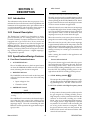
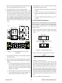
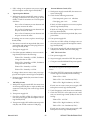
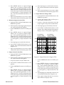
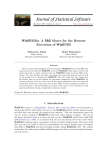
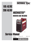
C. Diode Testing Basics
Testing of diode modules requires a digital volt/ohm
meter that has a diode test scale. Remember that even if
the diode module checks good, it may still be bad. If in
doubt, replace the diode module.
Art # A-00306
OL
1. Locate the diode module to be tested.
2. Remove cables from mounting studs on diodes to isolate the module.
Reverse Bias
Diode Not Conducting
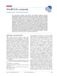
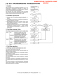
3. Set digital volt/ohm meter to diode test scale.
4. Using the Figures for each test, check each diode in
the module. Each diode must be checked in forward
bias (plus to negative) and reverse bias (negative to
plus) direction.
VR COM
_
+
Cathode
5. Connect the volt/ohm meter positive lead to the anode (+) of the diode and the negative lead to the cathode (-) of the diode for forward bias testing (refer to
Figure 4-A). A properly functioning diode will conduct in the forward bias direction and indicate between 0.3 to 0.9 volts.
A
Anode
Figure 4-B Testing Diode Reverse Bias
Art # A-00307
5. If a diode checks bad, replace the diode module.
6. Reconnect all cables to proper terminals.
0.75
D. Input Diode (D1) Without Inrush Circuit Test
Procedure
NOTE
Forward Bias
Diode Conducting
This test requires a digital volt meter with a diode
test scale.
Diode Test Symbol
Anode
VR COM
_
+
A
Perform a visual inspection of input diode(D1) assembly.
Most failures are identified by a fracture in the plastic
case of the device. If there are no signs of physical damage or failure then proceed with the following test procedure:
1. Disconnect lead #8 or #9 but not both from the input
diode (D1) assembly.
Cathode
Figure 4-A Testing Diode Forward Bias
6. Reverse the meter leads across the diode for reverse
bias testing (refer to Figure 4-B). A properly functioning diode will block in the reverse bias direction and
depending on the meter function will indicate an open
or "OL".
Manual 0-2433
2. Set meter on diode test scale.
3. The input diode (D1) assembly contains six standard
diodes connected in a three phase full wave circuit.
Three diodes are common to the negative terminal and
three three are common to the the positive terminal.
Test each diode in the forward (R, S, T to +) and reverse (R, S, T to -) direction as shown in Figure 4-C. A
properly functioning diode conducts in the forward
direction (plus to negative) and blocks in the reverse
direction (negative to plus).
21
SERVICE TROUBLESHOOTING
R
S
T
A-00308
A-00309
R S T
R2
G
Wire 9
Wire 9
+
Wire 8
Wire 8
+
S
R
T
S
R
+
G R2
D1
T
D1
+
Figure 4-D Testing Input Diode (D1) Assembly
(With Inrush Circuit)
Figure 4-C Testing Input Diode (D1) Assembly
(Without Inrush Circuit)
4. If any diode section does not check properly, replace
the input diode (D1) assembly per Section 5.03-D.
5. If the input diode (D1) assembly checks are correct,
reconnect the lead removed in Step 1 above.
E. Input Diode (D1) With Inrush Circuit Test
Procedure
NOTE
This test requires a digital volt meter with a diode
test scale.
Perform a visual inspection of input diode (D1) assembly. Most failures are identified by a fracture in the plastic case of the device. If there are no signs of physical
damage or failure then proceed with the following test
procedure:
1. Disconnect lead #10 from the negative terminal of input diode (D1) assembly.
4. If any diode section does not check properly, replace
the input diode (D1) assembly per Section 5.03-D.
5. To check the SCR in the input diode (D1) assembly
use the following procedure:
a. Remove the leads from terminals R-2, G, and positive
(+)
b. Check for shorts between R-2 and the (+) terminal.
c. Check the gate between G and (+) terminals for resistance of approximately 50 ohms.
d. If the SCR does not check properly, replace the input
diode (D1) assembly per Section 5.03-D.
e. If the SCR checks are correct, reconnect the leads removed in Step "a" above.
6. If the input diode (D1) assembly checks are correct,
reconnect the lead removed in Step 1 above.
F. Power IGBT (Q1 & Q2) Module Test
Procedure
2. Set meter on diode test scale.
3. The input diode (D1) assembly contains six standard
diodes and a SCR used for the inrush circuit. The diodes are connected to form a three phase full wave
circuit with three diodes connected to the negative
terminal and three three connected to the the R-2 terminal. Test each diode in the forward (R-2 to R, S, T)
and reverse (- to R, S, T) direction as shown in Figure
4-D. A properly functioning diode conducts in the
forward direction (plus to negative) and blocks in the
reverse direction (negative to plus).
SERVICE TROUBLESHOOTING
NOTE
This procedure requires a digital volt ohm meter
that has a diode test scale. A more conclusive test
requires specialized equipment. Therefore, even if
the IGBTpower module checks out good, it may
still be bad. If in doubt, replace the IGBT module.
Perform a careful inspection of each IGBT module (Q1 &
Q2). Most failures are identified by a fracture in the plastic case of the device. If there are no signs of physical
damage or failure then proceed with the following test
procedure:
22
Manual 0-2433
1. Disconnect all leads and bus bars from the IGBT module to be tested noting the location of each.
7. If IGBTchecks are correct, reinstall the IGBT module
using the following procedure:
2. Select the diode test scale on the digital meter.
3. The IGBT module contains two diode sections. One
diode is across C2E1 (anode) to C1 (cathode) and one
is across E2 (anode) to C2E1 (cathode). Test each diode section in the forward (anode to cathode) and reverse (cathode to anode) direction (refer to Figure 4E). A properly functioning diode conducts in the
forward direction (meter indicates 0.3 to 0.9 volts) and
blocks in the reverse direction (meter indicates an
open).
PCB8 or PCB9
G3
CN1
2
G1
E3
1
E1
G4
CN2
1
G2
E4
2
E2
b. Apply a thin layer of Dow Corning # 340 or
equivalent heatsink compound to the IGBT module.
c. Torque the IGBT module mounting screws to 27
inch-lbs.
G. Output Diode Test Procedure
This procedure requires a digital volt/ohm meter that has
a diode test scale. A more conclusive test requires specialized equipment. Therefore, even if the output diodes
check out good, it may still be bad. If in doubt, replace
the diode module.
Q1 or Q2
C1
A-00310
a. Clean the old heatsink residue from the heatsink
surface.
C2
E1
1. Locate output diodes in power supply to be tested.
Refer to Figure 4-F for style of output diodes being
tested.
Type 1 Diode
A
E2
Q2
C1
A
Cathode
CN2
K
PCB8
C2
Q1 E1
G1 E1
CN2
E2 G2
E2
E2
CN1
PCB9
G1 E1
CN1
C1
E2 G2
Anode
C2
E1
K
Type 2 Diode
A-00311
Figure 4-F Testing Output Diode
Figure 4-E Testing IGBT Module (Q1 & Q2)
Assembly
2. Remove cables from mounting studs on diodes.
NOTE
5. If any diode section does not check properly, replace
the IGBT module.
6. Select the ohms scale on the digital meter and check
the gates of the IGBT module using the following procedure:
a. Check the resistance between the gate and emitter circuit place the meter leads on CN1 connector pins 1 & 2 of the PC board soldered to the IGBT
module. A properly functioning IGBT module
should read 1k ohms.
b. Do the same for CN2 connector on the PC board.
c. If any IGBT module does not check properly, replace the IGBT module per Section 5.03-E.
In Type 2 diodes the cathode is mounted to the heat
sink.
3. Set meter on diode test scale.
4. Test diode in the forward and reverse direction by
conecting and then reversing the meter leads across the
diode. A properly functioning diode conducts in the
forward direction and blocks in the reverse direction.
5. If diode checks bad, replace diode module. Clean surface of heat sink where diode was mounted. Apply a
thin layer of heat sink compound (dow corning no.
340 or equivalent) to mounting surface on new diode.
Install new diode onto heat sink and torque to 27 inlbs.
6. Connect all cables to proper terminals.
Manual 0-2433
23
SERVICE TROUBLESHOOTING
If AC voltage is not present check control winding of transformer T1.
H. Input Capacitor (C4 & C5) Test Procedure
1. Check C4 & 5 for case damage (bulge and/or split).
Check with ohm meter for shorts or open circuit. Replace if necessary.
d. Check output DC voltage of power supply on control/logic board (PCB1) for the following:
2. Remove wire #10 from C5 capacitor.
TP2 to TP1
Regulated +15 VDC
3. Check resistor network R2 & 3 for proper values. See
parts list and exploded view for values and location.
Replace if necessary.
TP3 to TP1
Regulated -15 VDC
TP4 to TP1
Unregulated +24 VDC
TP5 to TP1
Unregulated -24 VDC
4. Check wires 93, 11, 94 to CN13 plug at control/logic
board (PCB1) for continuity. Replace if necessary.
TP1 is circuit common
5. Reconnect all connection.
I.
Vertical: 5 V/Div
Control/Logic Board (PCB1) Test Procedure
The control/logic PCB1 is divided into twelve tests. Each
test helps in determining if the control/logic PCB1 is
faulty. Perform each test in the order given.
Horizontal: 5 ms/Div
TP4
NOTE
TP2
All oscilloscope setting are for x1 probe.
For all test points on control/logic PCB1, use TP1 for logic
common. Some of the test points require a oscilloscope
with probe. Resistance checks are measured with power
supply turned off. Signal tests are measured with power
supply turned on.
0 Ref
A-00296
Figure 4-G TP2 and TP4 Waveforms
WARNING
Before disconnecting or connecting any connectors
or wiring turn the power supply OFF.
1.
Vertical: 5 V/Div
Horizontal: 5 ms/Div
0 Ref
Power Supply Circuit
a. Turn power supply OFF and disconnect wire #8
from D1.
b. Remove CN13 plug from control/logic board
(PCB1).
TP3
c. With power supply turned on, check AC input
voltage of power supply on control/logic board
(PCB1) at connector CN21 for the following:
TP5
CN21 pin 1 to 2
18 VAC
CN21 pin 3 to 2
18 VAC
A-00297
Figure 4-H TP3 and TP5 Waveforms
Pin 2 is common
SERVICE TROUBLESHOOTING
24
Manual 0-2433
e. If DC voltage is not present, turn power supply
OFF and replace control/logic board (PCB1).
2.
4.
a. With power supply turned OFF, disconnect connector CN18 plug.
Input Capacitor Balance
b. Check for the following resistances:
a. With power supply turned OFF, remove connector plug CN13 from the control/logic board
(PCB1). Check for resistance at CN13 receptacle
as follows:
CN18 receptacle, pins 1 to 2 4K ohms
CN18 plug, pins 1 to 2
3 ohms
Pin 1 to Pin 3 Continuity in one direction and
an open circuit in the other.
If check at CN18 receptacle is not correct, replace
control/logic board (PCB1).
Pin 3 to Pin 5 Continuity in one direction and
an open circuit in the other.
If check at CN18 plug is not correct, replace control/logic board (PCB1).
Pin 1 to Pin 5 Continuity in one direction and
an open circuit in the other.
c. Disconnect wire #8 from input diode (D1) on input rectifier.
If readings are not correct, replace control/logic
board (PCB1).
d. Turn power supply ON.
e. Check for +15 VDC at TP26. If voltage is not correct, turn power supply OFF and replace control/
logic board (PCB1).
b. Disconnect wire #8 from input diode (D1) on input rectifier and connector CN13 plug from control/logic board (PCB1).
f. Turn power supply OFF and reconnect input diode (D1) wire #8 and connector CN18 plug.
c. Turn power supply ON.
d. Check the capacitor imbalance circuit on control/
logic board (PCB1) for the following:
5.
LIFT TIG Circuit Test
a. Turn power supply ON.
TP22 to TP1 Normally +15 VDC; Unbalance
voltage less than 10 VDC
b. Set power supply controls for LIFT TIG operation.
c. Close pins A and B of REMOTE 14 pin receptacle.
TP23 to TP1 Normally +15 VDC; Unbalance
voltage less than 10 VDC
NOTE
TP24 to TP1 Normally +15 VDC
Do not touch Tungsten to work (open circuit condition).
TP25 to TP1 Normally +15 VDC
d. Check the LIFT TIG circuit (open condition) on
control/logic board (PCB1) for the following:
If voltage values are not correct, turn power supply OFF and replace control/logic board (PCB1).
TP38 to TP1 0 VDC
e. Reconnect input diode (D1) wire #8 and connector CN13 plug.
3.
Inverter Balance Circuit (CT1)
TP45 to TP1 Low Condition (0 VDC)
MCB Trip Circuit
TP47 to TP1 High Condition (+15 VDC)
a. With power supply turned OFF, disconnect wire
#8 from input diode (D1) on input rectifier and
connector CN20 plug from control/logic board
(PCB1).
If levels are not correct, turn power supply OFF
and replace control/logic board (PCB1).
e. Touch Tungsten to work (short circuit condition).
f. Check the LIFT TIG circuit (short circuit condition) on control/logic board (PCB1) for the following:
b. Turn power supply ON
c. Check for +24 VDC at TP27. If voltage is not correct, turn power supply OFF and replace control/
logic board (PCB1).
TP38 to TP1 +15 VDC
TP45 to TP1 High Condition (+15 VDC)
d. Turn power supply OFF and Reconnect input diode (D1) wire #8 and connector CN20 plug.
TP47 to TP1 Low Condition (0 VDC)
If levels are not correct, turn power supply OFF
and replace control/logic board (PCB1).
Manual 0-2433
25
SERVICE TROUBLESHOOTING
6.
Precharge Circuit Test
a. Turn power supply OFF.
Vertical: 5 V/Div
b. Turn power supply ON and check the precharge
circuit on control/logic board (PCB1) for the following:
Horizontal: 20 µs/Div
TP10
TP28 to TP1 0 VDC
0 Ref
TP29 to TP1 Normally 0 VDC; +15 VDC during initial charge
The indication at TP29 should start at 0 VDC, goto
+15 VDC for approximately 3 seconds, then return to 0 VDC.
TP12
0 Ref
If levels are not correct, turn power supply OFF
and replace control/logic board (PCB1).
7.
A-00304
Figure 4-I TP10 and TP12 Waveforms
Close Loop Current Feedback (CT2) Test
a. With power supply turned OFF, disconnect connector CN25 plug.
b. Turn power supply ON.
e. Turn power supply OFF and reconnect connector
CN25 plug.
8.
c. Check the close loop current feedback circuit on
control/logic board (PCB1) for the following at
CN25 receptacle:
Close Loop Voltage Feedback Test
a. With power supply turned OFF, disconnect connector CN22 plug.
b. Check CN22 plug, pins 1 to 4 for 0.4 ohms. If
check at CN22 plug is not correct, check wires #24
and #26 for loose connection. If wires are okay
then check CN22 connector on control/logic
board (PCB1) for 5 ohms from pin 1 to 4. If value
is not correct then replace the control/logic board.
Pin 1 to TP1 -15 VDC
Pin 2 to TP1 0 VDC; PCB Common
Pin 3 to TP1 0 to 4 VDC; 1 VDC per 100
Amps of output current
Pin 4 to TP1 +15 VDC
c. Turn power supply ON.
If voltage values are not correct, turn power supply OFF and replace control/logic board (PCB1).
d. Check the close loop voltage feedback circuit on
control/logic board (PCB1) for the following:
d. Check the close loop current feedback circuit on
control/logic board (PCB1) for the following:
TP13 to TP1 0 to 7 VDC; 1 VDC per 10 V of
output voltage
TP12 to TP1 0 to 4 VDC; 1 VDC per 100
Amps of output current
If voltage value is not correct, turn power supply
OFF and replace control/logic board (PCB1).
TP37 to TP1 0 VDC; +15 VDC when output
current detected
If voltage values are not correct, turn power supply OFF and replace control/logic board (PCB1).
SERVICE TROUBLESHOOTING
26
Manual 0-2433
10. AMPERAGE Test
TP10 Settings
Vertical: 5 V/Div
Horizontal: 20 µs/Div
a. Turn power supply ON.
TP13 Settings
Vertical: 2 V/Div
Horizontal: 20 µs/Div
b. Check the AMPERAGE output reference signal
on control/logic board (PCB1) for the following:
TP10
TP9 to TP1
0 Ref
0 to +10 VDC
If level is not correct, turn power supply OFF and
replace control/logic board (PCB1).
Vertical: 5 V/Div
TP13
Horizontal: 20 µs/Div
TP9
0 Ref
A-00305
0 Ref
Figure 4-J TP10 and TP13 Waveforms
TP11
e. Turn power supply OFF and reconnect connector
CN22 plug.
9.
0 Ref
ARC Control Test
A-00303
a. Turn power supply ON.
Figure 4-L TP9 and TP11 Waveforms
b. Check the ARC control circuit on control/logic
board (PCB1) for the following:
c. On front panel of power supply set AMPERAGE
switch to PANEL position.
TP11 to TP1 0 to +10 VDC
If level is not correct, turn power supply OFF and
replace control/logic board (PCB1).
d. Check the AMPERAGE reference signal on control/logic board (PCB1) for the following:
TP10 to TP1 0 to +7 VDC
Vertical: 5 V/Div
If level is not correct, turn power supply OFF and
replace control/logic board (PCB1).
Horizontal: 20 µs/Div
TP9
TP10 Settings
Vertical: 5 V/Div
Horizontal: 20 µs/Div
0 Ref
TP13 Settings
Vertical: 2 V/Div
Horizontal: 20 µs/Div
TP10
0 Ref
TP11
0 Ref
TP13
A-00303
0 Ref
Figure 4-K TP9 and TP11 Waveforms
A-00305
Figure 4-M TP10 and TP12 Waveforms
Manual 0-2433
27
SERVICE TROUBLESHOOTING
11.
g. Disconnect CN9, CN10, CN11, and CN12 from
the control/logic board (PCB1).
IC1 & Gate Drive Test
a. Turn power supply OFF and disconnect wire #8
from D1.
h. Turn power supply ON.
b. Turn power supply ON.
i. Check pulse transformer drive per the following
(refer to Figures 4-O and 4-P):
c. On front panel of power supply set contactor
switch to PANEL position.
TP18 to TP1 20 V (Approx.) Square Wave
d. Check the inverter ON/OFF signal on control/
logic board (PCB1) for the following:
TP19 to TP1 20 V (Approx.) Square Wave
TP20 to TP1 20 V (Approx.) Square Wave
TP14 to TP1 0 VDC (Inverter running)
TP21 to TP1 20 V (Approx.) Square Wave
+14 VDC (Inverter Stopped)
If signals are not correct, turn power supply OFF
and replace control/logic board (PCB1).
If voltage values are not correct, turn power supply OFF and replace control/logic board (PCB1).
e. Check to verify output of IC1 pulse waveform per
the following:
Vertical: 10 V/Div
Horizontal: 20 µs/Div
TP16 to TP1 15 V Square Wave
TP18
TP17 to TP1 15 V Square Wave
0 Ref
If signals are not correct, turn power supply OFF
and replace control/logic board (PCB1).
Vertical: 5 V/Div
Horizontal: 20 µs/Div
TP20
0 Ref
A-00301
TP16
Figure 4-O TP18 and TP20 Waveforms No Load
Condition
0 Ref
Vertical: 10 V/Div
Horizontal: 20 µs/Div
TP17
TP18
0 Ref
0 Ref
A-00295
Figure 4-N TP16 and TP17 Waveforms
TP20
f. Turn power supply OFF and reconnect wire #8 to
D1.
0 Ref
A-00300
Figure 4-P TP18 and TP20 Waveforms Rated Load
Condition
SERVICE TROUBLESHOOTING
28
Manual 0-2433
J. HF TIG Circuit Test
1. With power supply turned OFF, check the resistance of R18 (300 ohms).
2. Turn power supply ON and check for 200 VAC
between CN4 pin 1 of TIG Sequencer PCB2 and
CN1 pin 63 of High Frequency PCB3.
If level is not correct, turn OFF power supply and
replace TIG Sequencer PCB2.
3. Check the signals for the High Frequency circuit
on the control/logic board (PCB1) for the following at CN19 receptacle:
To properly make the adjustments described in this Subsection requires the use of an oscilloscope and probes.
Do not attempt to make the adjustments with only a meter.
NOTE
All oscilloscope setting are for x1 probe.
A. Versions
These adjustments apply only to the following versions
or later of the Control/Logic printed circuit board (PCB1):
Model (Type)
PCB1 Number
208-230/460 VAC
WK-2611, U06
Pin 1 to TP1 0 VDC; PCB Common
460/575 VAC
WK-2611 S01, U07
Pin 3 to TP1 +15 VDC
380/415 VAC
WK-2611 S02, U08
Pin 4 to TP1 0 VDC (Inverter OFF)
B. Adjustment References
+7.5 VDC (Inverter ON)
The function of each adjustment and it's reference designation are as follows:
Pin 5 to TP1 0 VDC (OUTPUT CONTACTOR to ON)
+15 VDC (OUTPUT CONTACTOR to REMOTE 14)
Pin 6 to TP1 0 VDC (OUTPUT CONTACTOR to REMOTE 14 or Process Selector to
STICK mode)
+15 VDC (OUTPUT CONTACTOR to ON except STICK mode)
Pin 7 to TP1 +24 VDC
If signals are not correct, turn OFF power supply
and replace control/logic board (PCB1).
4. Turn power supply OFF.
4.08 Control/Logic Board (PCB1)
Adjustments
Reference
Description
VR1
Output Current Minimum
VR2
Output Current Maximum
VR3
Output Current Limit
VR4
Dead Time
VR5
Basic Oscillation
VR6
Output Voltage Detection
VR10
Minimum Pulse Width for LIFT TIG
VR11
MINI LINK Threshold Level
C. Special Adjustment
Models (type) 460/575 VAC sold in Canada must have
the MINI LINK adjusted properly as follows:
If the input voltage is to be less than 505 VAC then
adjust VR11 to turn ON the MINI LINK.
The Control/Logic printed circuit board (PCB1) has various adjustments on it. These adjustments must be properly set for the power supply to operate properly.
WARNING
If the input voltage is to be greater than 515 VAC then
adjust VR11 to turn OFF the MINI LINK.
D. Adjustments
1. Initial Setup
The unit must be set to the following conditions before making any adjustments:
These adjustments require that the unit be powered on. High voltages and currents will be present.
Use extreme caution when making adjustments.
a. PROCESS selector to STICK Mode
b. OUTPUT CONTACTOR selector to REMOTE
14
Manual 0-2433
29
SERVICE TROUBLESHOOTING
c. AMPERAGE selector to PANEL
d. Amperage (A) control fully counter clockwise
Vertical: 5 V/Div
e. ARC control fully counter clockwise
Horizontal: 5 µs/Div
OUTPUT CONTACTOR to ON
f. No Remote Connection
TP16
2. Basic Oscillation (VR5)
a. Connect the channel of the oscilloscope to
TP15 and the common to TP1.
0 Ref
Dead Time
b. Turn ON power to the unit.
c. The sawtooth waveform should be approximately 3.2 volts at 31.5µs (refer to Figure 4Q).
TP17
0 Ref
Vertical: 1 V/Div
OUTPUT CONTACTOR to REMOTE 14
Horizontal: 10 µs/Div
A-00313
Figure 4-R Dead Time at TP16 and TP17
TP15
c. If the waveform is not correct, adjust VR4 for
the correct waveform.
0 Ref
4. Minimum Output Current (VR1)
a. Set the OUTPUT CONTACTOR selector to the
REMOTE 14 position.
b. Short output by connecting negative and positive output terminal leads together.
c. Set the AMPERAGE selector to PANEL position.
A-00312
d. Place METER selector on optional Digital
Meter to the ‘A’ position to indicate amperage. If the optional Digital Meter is not installed then use a clamp on amperage meter
around the output loop between the positive
(+) and negative (-) output terminals of the
unit.
Figure 4-Q Basic Oscillation Waveform at TP15
d. If the waveform is not correct, adjust VR5 for
the correct waveform.
3. Dead Time (VR4)
e. Adjust the amperage (A) control until the
meter indicates 5 amperes.
a. Connect the one channel of the oscilloscope to
TP16, one channel to TP17 and the common
to TP1.
f. Turn amperage (A) control fully counterclockwise.
b. The dead time is the time between the trailing
edge of the waveform at TP16 and the leading
edge of the waveform at TP17 (refer to Figure
4-R). This time should be approximately 2µs.
SERVICE TROUBLESHOOTING
g. Set OUTPUT CONTACTOR selector to ON
position.
30
Manual 0-2433
h. Place METER selector on optional Digital
Meter to the ‘A’ position to indicate amperage. If the optional Digital Meter is not installed then use a clamp on amperage meter
around the output loop between the positive
(+) and negative (-) output terminals of the
unit. The current indicated should be 5 amperes (± 1).
g. Turn amperage (A) control fully clockwise.
The current indicated should be 410 amperes
(± 5).
h. If the current indication is not correct, adjust
VR3 until the meter indicates the proper value.
7. Output Detection Voltage (VR6)
a. Set the OUTPUT CONTACTOR selector to the
REMOTE 14 position.
i. If the current indication is not correct, adjust
VR1 until the meter indicates the proper value.
b. Connect the channel of the oscilloscope to
TP13 and the common to TP1.
5. Maximum Output Current (VR2)
a. Set the OUTPUT CONTACTOR selector to the
REMOTE 14 position.
c. Connect a 5 ohm 100 watt resistor across the
output negative and positive terminal leads.
b. Short output by connecting negative and positive output terminal leads together.
d. Turn amperage (A) control fully clockwise.
e. Set OUTPUT CONTACTOR selector to ON
position. The voltage should go from approximately 0 volts to 7 volts (refer to Figure 4-S)
c. Set the AMPERAGE selector to PANEL position.
d. Place METER selector on optional Digital
Meter to the ‘A’ position to indicate amperage. If the optional Digital Meter is not installed then use a clamp on amperage meter
around the output loop between the positive
(+) and negative (-) output terminals of the
unit.
TP10 Settings
Vertical: 5 V/Div
Horizontal: 20 µs/Div
TP13 Settings
Vertical: 2 V/Div
Horizontal: 20 µs/Div
TP10
0 Ref
e. Turn amperage (A) control fully clockwise.
g. Set OUTPUT CONTACTOR selector to ON
position. The current indicated should be 375
amperes (± 5).
TP13
i. If the current indication is not correct, adjust
VR2 until the meter indicates the proper value.
0 Ref
6. Output Current Limit (VR3)
A-00305
a. Set the OUTPUT CONTACTOR selector to the
REMOTE 14 position.
Figure 4-S Output Detection Voltage at TP13
b. Short output by connecting negative and positive output terminal leads together.
f. Set the AMPERAGE selector to PANEL position.
c. Set process selector switch to MIG mode.
d. Set OUTPUT CONTACTOR selector to ON
position.
g. Place METER selector on optional Digital
Meter to the ‘A’ position to indicate amperage. If the optional Digital Meter is not installed then use a clamp on amperage meter
around the output loop between the positive
(+) and negative (-) output terminals of the
unit.
e. Set the AMPERAGE selector to PANEL position.
f. Place METER selector on optional Digital
Meter to the ‘A’ position to indicate amperage. If the optional Digital Meter is not installed then use a clamp on amperage meter
around the output loop between the positive
(+) and negative (-) output terminals of the
unit.
Manual 0-2433
h. Turn amperage (A) control fully clockwise. The
current indicated should be 5 amperes (± 1).
i. If the output voltage detection is not correct,
adjust VR6 for the proper value.
31
SERVICE TROUBLESHOOTING
8. Minimum Pulse Width For LIFT TIG (VR10)
a. Connect the channel of the oscilloscope to
TP16 and the common to TP1.
b. The pulse width of the displayed waveform
should be 2µs (±0.1).
c. If the minimum pulse width is not correct, adjust the width using VR10 for the proper value.
Vertical: 5 V/Div
Horizontal: 5 µs/Div
The following describes each model and their SMARTLINK operation:
230/460 volt model:
When MCB1 is turned on, the Logic Board samples the
incoming primary voltage between L1 & L2. With 230
volt single or three phase input voltage applied, the logic
board will send a signal to MC-2 to close. A time delay of
3 to 4 seconds will be noticed before MC-2 energizes.
When MC-2 closes the input power devices and control
transformer will change from a series configuration to a
parallel configuration. When 460 volt input voltage is
applied, MC-2 is not energized. The power devices and
control transformer stay in a series configuration.
380-415 volt model:
TP16
MC-2 contactor is not required to parallel or series the
input power circuitry as in the 230/460 volt model. When
MCB is turned on the logic board only requires the inrush circuitry to operate.
0 Ref
460-575 volt model:
A-00302
Figure 4-T Minimum Pulse Width at TP16
4.09 Circuit Descriptions
When MCB1 is turned on, the Logic Board samples incoming primary voltage between L1 & L2. With 460 volt
supplied, the Logic Board will send a signal to MC-2 to
close. A time delay of 3 to 4 second will be noticed before
MC-2 energizes. When MC-2 closes the control transformer will configure to 460 volt on the primary windings. This is referred to as Mini Link. The input Power
circuit remains in the same configuration for 460 & 575
volt input.
A. SMART LINK Operation
Smart Link incorporates a Inrush circuit and input voltage sensing circuit. When MCB1 is turned on the Inrush
circuit provides a precharging of the input capacitors.
MC-1 will close after the input capacitors have charged
to full operating voltage. Aprox. 5 seconds to charge the
input capacitors. During precharge the control/logic
board is sensing the input voltage and configuring the
input power circuit and control transformer to match the
input voltage. The Power Supply is configured to the
highest input voltage when MCB1 is in the OFF position
as follows:
230/460 model configured to 460 volt
380-415 model configured to 415 volt
460/575 model configured to 575 volt
SERVICE TROUBLESHOOTING
32
Manual 0-2433
SECTION 5:
REPAIRS & REPLACEMENT
PROCEDURES
3. Attach the copper foil to a convenient and exposed
electrical ground.
4. Connect the power supply primary cable ground to
the same electrical ground as the wrist strap.
5. Open the power supply enclosure and remove the
failed PC board.
5.01 Introduction
This Section describes parts replacement procedures and
all cable repairs which may be performed on the Model
300GTS Inverter Arc Welder.
Under not circumstances are field repairs to be attempted
on Printed Circuit or other Subassemblies of this unit.
Evidence of unauthorized repairs may void the factory
warranty.
6. Carefully open the ESD protective bag and remove
the replacement PC board.
7. Install the replacement PC board in the power supply
and make all necessary connections.
8. Place the failed PC board in the ESD protective bag
and seal for return shipping.
9. Reassemble the power supply enclosure.
5.02 Anti-Static Handling
Procedures
10. Remove the grounding wrist strap from your wrist
and from the electrical ground connection before reconnecting primary power to the power supply.
A. General
5.03 Disassembly & Replacement
CAUTION
WARNING
PC boards can be irreparably damaged by improper
handling due to electrostatic discharge (ESD).
Replacement PC boards are shipped in a protective enclosure to prevent damage from electrostatic discharge
(ESD) during shipping. Included with each replacement
board is a ground strap to prevent static damage during
installation.
WARNINGS
Read and understand these instructions and the
instructions on the grounding wrist strap package
before opening the power supply enclosure or removing the replacement PC board from its protective enclosure.
Disconnect primary power to the system before disassembling the power supply enclosure.
Do not operate the power supply or test equipment
under power while wearing the grounding wrist
strap.
Disconnect primary power at the source before assembling or disassembling this unit.
A. Opening Enclosure
1. Turn off MCB1 of power source and open wall disconnect switch or circuit breaker.
2. Wait at least two minutes to allow discharge time of
input capacitors.
3. Remove the two screws on the bottom of the unit securing the plastic enclosure to the metal framing of
the unit.
4. Remove the ten bolts securing the rest of the plastic
enclosure to the metal framing.
5. To remove the plastic enclosure pull it open, away
from the top of the frame, and slide it up from the
bottom.
6. Close the enclosure by reversing the above steps.
B. Fuse Replacement
B. Procedure
1. Open the unit as described in paragraph “A” above.
1. Open the wrist strap and unwrap the first two folds
of the band. Wrap the adhesive side firmly around
your wrist.
2. Locate and remove the old fuse.
3. Install the replacement fuse and close up the power
supply by reversing the procedure in Step 1.
2. Unroll the rest of the band and peel the liner from the
copper foil at the opposite end.
Manual 0-2433
33
REPLACEMENT PROCEDURES
C. Control/Logic PCB Assembly Replacement
D. Input Diode (D1) Replacement
1. Open the unit as described in paragraph “A” above.
The procedure is the same for both types of input diode
(D1) assemblies with or without the inrush circuit.
2. Carefully remove all cable connections to the Control/
Logic PCB Assembly noting the location of each.
3. Slide the PCB up and out of the unit.
4. Set the switches on the replacement PCB the same as
the one removed.
1. Open the unit as described in paragraph “A” above.
2. Mark and disconnect all leads to the input diode (D1)
assembly.
3. Remove the screws securing the input diode (D1) assembly to the heatsink.
NOTE
4. Carefully remove the old input diode (D1) assembly.
Be sure that the switches on the replacement PCB
are set the same as the old PCB.
5. Clean the residue of old heatsink compound from the
surface where the input diode (D1) was installed.
5. Reinstall the replacement Control/Logic PCB Assembly by reversing the above procedure and noting the
following:
6. Apply a thin layer of Dow Corning #340 or equivalent heatsink compound to the mounting surface of
the replacement input diode (D1) assembly.
Connector
CN1
HOT LEVEL Potentiometer
7. Install the replacement input diode (D1) assembly onto
the heatsink and secure in place with the screws removed in Step 3 above.
CN2
AMPERAGE Potentiometer
8. Torque the screws to 20 inch-lbs.
CN3
Contactor Switch
CN4
AMPERAGE signal selector switch and
output to Filter PCB
9. Reconnect all leads removed in Step 2 above to the
proper terminals.
CN5
Process selector switch
CN6
Optional Digital meter
CN8
REMOTE 14 pin receptacle pins M & N
CN9
G1/E1 of IGBT Q1
CN10
G1/E1 of IGBT Q2
CN11
G2/E2 of IGBT Q1
CN12
G2/E2 of IGBT Q2
CN13
Input capacitor imbalance circuit
CN14
Inrush contactor coil
CN15
Control voltage to drive MC2
CN16
Smart Link & Mini Link contactor
CN17
Mechanical state sense
CN19
TIG Sequencer and HF control
CN18
Over-current detect of IGBT
CN20
Trip coil
CN21
AC supply for control/logic board
CN22
Main transformer AC output voltage
sense
CN23
DC output detect
8. Install the replacement IGBT module (Q1 or Q2) assembly onto the heatsink and secure in place with the
screws removed in Step 3 above.
CN25
Output current detect
9. Torque the screws to 20 inch-lbs.
CN26
Power & Warning lamp
CN27
Temperature sensors
10. Reconnect all leads and bus bars removed in Step 2
above to the proper terminals.
CN28
Arc control potentiometer
Description of Cable
REPLACEMENT PROCEDURES
E. IGBT Module (Q1 or Q2) Replacement
1. Open the unit as described in paragraph “A” above.
2. Mark and disconnect all leads to the IGBT module
(Q1 or Q2) assembly.
3. Remove the screws securing the IGBT module (Q1 or
Q2) assembly to the heatsink.
4. Using a 30 watt soldering iron remove IGBT Gate PCB
(PCB8) or IGBT Gate PCB (PCB9) from the IGBT module to be replaced.
5. Carefully solder IGBT Gate PCB (PCB8) or IGBT Gate
PCB (PCB9) to the replacement IGBT module.
NOTE
Be careful to not over heat the gate and emitter
terminals when soldering as damage to the module will occur.
6. Clean the residue of old heatsink compound from the
surface where the IGBT module was installed.
7. Apply a thin layer of Dow Corning #340 or equivalent heatsink compound to the mounting surface of
the replacement IGBT module (Q1 or Q2).
34
Manual 0-2433
SECTION 6:
PARTS LISTS
6.01 Introduction
A. Parts List Breakdown
The parts list provide a breakdown of all replaceable components. The parts lists are arranged as follows:
Section 6.03: Complete Systems
Section 6.04: Replacement Parts (Before January
1994)
Section 6.05: Replacement Parts (January 1994 and
After)
NOTE
Parts listed without item numbers are not shown,
but may be ordered by the catalog number shown.
B. Returns
If a Thermal Dynamics product must be returned for service, contact your Thermal Arc distributor. Materials returned to Thermal Dynamics without proper authorization will not be accepted.
6.02 Ordering Information
Order replacement parts by catalog number and complete description of the part or assembly, as listed in the
parts list for each type item. Address all inquiries to your
authorized Thermal Dynamics distributor.
6.03 Complete Systems
Complete systems include: Power supply with primary
power cable, two male plugs, and operating manual.
Catalog #
Description
10-1004
208/230/460 VAC, 50/60 Hz, Single/
Three-Phase
380/400/415 VAC, 50/60 Hz, Single/
Three-Phase
575 VAC, 50/60 Hz, Single/ThreePhase
10-1005
10-1006
Manual 0-2433
35
PARTS LISTS
6.04 Replacement Parts (Before January 1994)
The parts in the following parts list are for units manufactured before January 1994. Locate the part required by the
"Reference" column and then go across to the type ("Model") column. The catalog number for the part is listed for
each type model. Parts with "—" are not used on that type model.
Reference
PL1/PL2
F1
F2 & F3
CT1
CT2
S1
S2 & S3
MC1
MC2
THS1 & THS2
MCB1
VR1, VR2 & VR3
VR4 & VR5
R1
R2 & R3
R4 & R5, R10 - R13
R6-R9
R14 & R15
R18
R19
C4 & C5
C6- C9
C10 & C13
C14 & C15
C17
C18 & C19
C20
Q1 & Q2
D1
D2 & D3
D4 & D5
D6 & D7
SA6 & SA7
FAN
T1
T2
T3
FCH
CON1
SOL
PCB1
PCB2
PCB3
PCB4
PCB7
PCB8 & PCB9
PCB10
TO
PARTS LISTS
Qty
1
1
1
1
1
1
1
1
1
1
1
1
1
1
1
1
1
1
1
1
1
1
1
1
1
1
1
1
1
1
1
1
1
1
1
1
1
1
1
1
1
1
1
1
1
1
1
1
1
1
4
Description
Pilot Lamp Assembly
Fuse 3A 600V
Fuse 2A, 250V
Current Transformer
Current Transformer
Process Selector Switch
Amperage & Contactor Switches
Magnetic Contactor
Magnetic Contactor
Aux. Contacts for 10-2118
Thermal Switch
Molded Case C.B.
Amperage, Arc & Hot Level Controls
Pre & Post Flow Controls
Resistor
Resistor
Resistor
Resistor
Resistor
Resistor
Resistor
Capacitor
Capacitor
Capacitor
Capacitor
Capacitor
Capacitor
Capacitor
Transistor
Diode
Diode
Diode
Diode
Surge Surpressor
Cooling Fan
Transformer
Transformer
Transformer
DC Reactor
14-Pin Receptacle
Solenoid Valve
Control/Logic PCB
Gas Control PCB
High Frequency PCB
Filter PCB
Optional Digital Panel Meter PCB
IGBT Gate PCB
Surge Absorber PCB
Output Terminal
Case Left & Right Side
Rubber Foot
36
Model
230/460
Model
380/415
Model
460/575
10-2236
10-2237
10-2206
10-2160
10-2161
10-2240
10-2239
10-2117
10-2118
10-2287
10-2238
10-2116
10-2124
10-2125
10-2207
10-2209
10-2211
10-2212
10-2213
10-2214
10-2228
10-2120
10-2119
10-2215
10-2217
10-2241
10-2219
10-2220
10-2113
10-2158
10-2111
10-2112
10-2110
10-2221
10-2159
10-2224
10-2149
10-2153
10-2225
10-2135
10-2154
10-2104
10-2108
10-2109
10-2163
10-2146
—
10-2164
10-2227
10-2202
10-2244
10-2236
10-2237
10-2206
10-2160
10-2161
10-2240
10-2239
10-2117
—
—
10-2238
10-2115
10-2124
10-2125
10-2207
10-2209
10-2211
10-2212
10-2213
10-2214
—
10-2120
10-2119
10-2215
10-2217
10-2241
10-2219
—
10-2113
10-2156
10-2111
10-2112
10-2110
10-2221
10-2159
10-2222
10-2148
10-2151
10-2225
10-2135
10-2154
10-2102
10-2108
10-2109
10-2163
10-2146
10-2147
10-2145
10-2227
10-2202
10-2244
10-2236
10-2237
10-2206
10-2160
10-2161
10-2240
10-2239
10-2117
10-2242
—
10-2238
10-2115
10-2124
10-2125
10-2207
10-2210
10-2211
10-2212
10-2213
10-2214
—
10-2121
10-2119
10-2216
10-2217
10-2241
10-2219
—
10-2114
10-2157
10-2111
10-2112
10-2110
10-2221
10-2159
10-2223
10-2155
10-2153
10-2225
10-2135
10-2154
10-2103
10-2108
10-2109
10-2163
10-2146
—
10-2165
10-2227
10-2202
10-2244
Manual 0-2433
MCB
THS1
PCB4
T2
F1
& F3
PCB1
D6
PCB3
D1
Right Side Before
January 1994
T1
FAN
PCB10
D7
CT2
FCH R2
& THS3
CC
R3
THS2
R1
MC1
MC2
A-00467
C5
C4
R10
R11
R12
Left Side Before
January 1994
R13
R4
R5
C8
PCB9
CT1
A-00469
Manual 0-2433
37
C7
C9
Q2
Q1
C6
PCB8
PARTS LISTS
6.05 Replacement Parts (January 1994 and After)
The parts in the following parts list are for units manufactured in and after January 1994. Locate the part required by
the "Reference" column and then go across to the type ("Model") column. The catalog number for the part is listed
for each type model. Parts with "—" are not used on that type model.
Reference
Qty
PL1/ PL2
F1
F2 & F3
CT1
CT2
S1
S2 &S3
MC2
1
1
1
1
1
1
1
1
1
1
1
1
1
1
1
1
1
1
1
1
1
1
1
1
1
1
1
1
1
1
1
1
1
1
1
1
1
1
1
1
1
1
1
1
1
1
1
1
1
1
THS1 & THS2
MCB1
SOL
VR1 & VR2
VR4 & VR5
R1
R2 & R3
R6 - R9
R10 - R13
R14 & R15
R18
R19
C4 & C5
C6- C9
C10 & C13
C14 & C15
C17
C18 & C19
C20
C21
C22
Q1 & Q2
Q1
D1
D6 & D7
SA7
FAN
T1
T2
FCH
CON1
PCB1
PCB2
PCB3
PCB4
PCB7
PCB8 & PCB9
PCB10
TO
CC
PARTS LISTS
Description
Pilot Lamp Assembly
Fuse 5A 600V
Fuse 2A, 250V
Current Transformer
Current Transformer
Switch
Switch
Magnetic Contactor
Aux. Contacts for 10-2118
Thermal Switch
Molded Case C.B.
Solenoid Valve
Amperage & Arc Controls
Pre & Post Flow Controls
Resistor
Resistor
Resistor
Resistor
Resistor
Resistor
Resistor
Capacitor
Capacitor
Capacitor
Capacitor
Capacitor
Capacitor
Capacitor
Capacitor
Capacitor
Transistor
Transistor
Diode
Diode
Surge Surpressor
Cooling Fan
Transformer
Transformer
DC Reactor
14-Pin Receptacle
Control/Logic PCB
Gas Control PCB
High Frequency PCB
Filter PCB
Optional Digital Panel Meter PCB
IGBT Gate PCB
Surge Absorber PCB
Output Terminal
Coupling Coil
Case Left & Right Side
38
Model
230/460
Model
380/415
Model
460/575
10-2236
10-2274
10-2206
10-2160
10-2161
10-2196
10-2252
10-2118
10-2287
10-2238
10-2116
10-2154
10-2124
10-2125
10-2207
10-2209
10-2212
10-2211
10-2213
10-2275
10-2228
10-2120
10-2119
10-2215
10-2217
10-2241
10-2219
10-2220
10-2270
10-2637
10-2113
—
10-2653
10-2630
10-2221
10-2159
10-2650
10-2149
10-2632
10-2135
10-2648
10-2108
10-2109
10-2163
10-2146
—
10-2164
10-2227
10-2633
10-2202
10-2236
10-2274
10-2206
10-2160
10-2161
10-2196
10-2252
—
—
10-2238
10-2115
10-2154
10-2124
10-2125
10-2207
10-2209
10-2212
10-2211
10-2213
10-2275
—
10-2120
10-2119
10-2215
10-2217
10-2241
10-2219
—
10-2270
10-2637
—
10-2628
10-2629
10-2630
10-2221
10-2159
10-2631
10-2148
10-2632
10-2135
10-2647
10-2108
10-2109
10-2163
10-2146
10-2147
10-2145
10-2227
10-2633
10-2202
10-2236
10-2274
10-2206
10-2160
10-2161
10-2196
10-2252
10-2242
—
10-2238
10-2115
10-2154
10-2124
10-2125
10-2207
10-2210
10-2212
10-2211
10-2213
10-2275
—
10-2121
10-2119
10-2216
10-2217
10-2241
10-2219
—
10-2270
10-2637
10-2114
—
10-2629
10-2630
10-2221
10-2159
10-2655
10-2155
10-2632
10-2135
10-2649
10-2108
10-2109
10-2163
10-2146
—
10-2165
10-2227
10-2633
10-2202
Manual 0-2433
MCB
D6
THS1
PCB4
F1
& F3
PCB1
T2
PCB3
D1
T1
Right Side January 1994
and After
FAN
PCB10
D7
CT2
FCH R2
& THS3
CC
R3
THS2
A-00468
R1
MC1
C5
C4
R10
R11
R12
R13
Left Side January 1994
and After
R4
R5
C8
PCB9
CT1
A-00470
Manual 0-2433
39
C7
C9
Q2
Q1
C6
PCB8
PARTS LISTS
PARTS LISTS
40
Manual 0-2433
APPENDIX I: CONTROL/LOGIC BOARD (PCB1)
CONNECTOR REFERENCE
Connector
Reference
CN1
VR3
HOT LE VE L Potentiometer connectioins
CN2
VR1
Amperage (A) Potentiometer connections
CN3
PCB 6-2
Contactor S witch
CN4
PCB 6-3
AMPE RAGE s ignal s elector s witch and F ilter board
CN5
PCB 6-1
Proces s s elector s witch
CN6
PCB 7
CN8
Optional Digital Meter connection
T o 14 pin receptacle pins M & N
CN9
PCB 8
G1/E 1 of IGB T Q1
CN10
PCB 9
G1/E 1 of IGB T Q2
CN11
PCB 8
G2/E 2 of IGB T Q1
CN12
PCB 9
CN13
G2/E 2 of IGB T Q2
Input capacitor imbalance circuit
CN14
MC1
CN15
T2
Inrus h contactor coil
Control voltage to drive MC2
CN16
MC2
S mart Link & Mini Link contactor
CN17
MC2
Mechanical s tate s ens e
CN18
CT 1
Over current detect of IGB T
CN19
T IG S equencer controls
CN20
MCB 1
CN21
T2
AC s upply for control/logic board
CN22
T1
Main trans former AC output voltage s ens e
CN23
Manual 0-2433
Des cription
T rip coil
DC output detect - Us ed on LIF T T IG models only
CN25
CT 2
Output current detect
CN26
PL1 /PL2
Power & warning lamp
CN27
T HS 1/T HS 2
CN28
VR2
T emperature s ens ors
Arc control potentiometer
41
APPENDIX
APPENDIX II: CONTROL/LOGIC BOARD (PCB1)
CONNECTOR SIGNALS
Connector
CN1
Pin
1
2
3
4
5
Value
0V
0 to +10 VDC
0 to +10 VDC
Description
Mimimum level of hot current signal
Reference signal of hot current signal; Return from VR3
Amp/ volt reference signal for use with hot start current level
Not Used
Not Used
CN2
1
2
3
4
0V
0 to +10 VDC
+10 VDC
Minimum level of amp/ volt signal
Reference signal of amp/ volt from amp/ volt adjuster (VR1)
Maximum level of amp/ volt signal
Not used
CN3
1
2
0V
0V
+24 VDC
CN4
1
2
3
0V
0 to +10 VDC
0 to +10 VDC
CN5
1
2
3
4
5
6
+15 VDC
+15 VDC
+15 VDC
+15 VDC
+15 VDC
+15 VDC
CN6
1
2
3
4
5
6
7
+15 VDC
0V
-15 VDC
0 to +15 VDC
0 to +10 VDC
0 to +4 VDC
CN8
1-2
Continuity
CN9
1-2
+18 V peak
Gate pulse output
CN10
1-2
3
+18 V peak
Not used
Not used
CN11
1-2
+18 V peak
Gate pulse output
CN12
1-2
3
+18 V peak
Gate pulse output
Not used
CN13
1
2
3
4
5
CN14
APPENDIX
Circuit common and chassis common
Contactor OFF
CONTACTOR, signal when PANEL position
PCB common
Remote amperage control input command signal
Remote amperage reference signal
When select NIG process
When select SCRATCH TIG process
When select HF TIG process
When select LIFT TIG process
When select STICK process
Process selection signal
PCB common
Amp/ volt preset signal
Amp/ volt preset signal
+1 VDC per 10 VDC of output
+1 VDC per 100 A of output
Not used
Dry contact when output current is detected
Connect with C4 (-)
Not used
Connect with cross point of R2 and R3
Not used
Connect with C5 (+)
Dry contact as drive MC1
1-2
NOTE - All values with respect to test point TP1 on main PCB1 logic board.
42
Manual 0-2433
Connector
CN15
CN16
CN17
CN18
CN19
Pin
1
2
3
4
5
1
2
3
1
CN22
CN23
CN25
CN26
CN27
CN28
Manual 0-2433
100 VAC
0V
+10 VDC
+15 VDC
4
0 to +7.5 VDC
6
CN21
100 VAC
Not used
100 VAC
100 VAC
1-2
1
2
3
5
CN20
Value
250 VAC
0V
Description
Normal close of CR5 on PCB1
Not used
Normal open of CR5 on PCB1
Common of CR5 on PCB1
Normal open of CR2 on PCB1
Not used
Common of CR2 onf PCB1
MC2 off
MC2 off or no contact of MC2
Current w aveform of IGBT,1V peak of 24 A peak
PCB common
Not used
Inverter signal OFF (0 VDC); ON (+15 VDC)
0 to +15 VDC
Output current detect - OUTPUT CONTACTOR to ON (0 VDC);
OUTPUT CONTACTOR to REMOTE 14 (+15 VDC)
0 to +15 VDC
OUTPUT CONTACTOR TO REMOTE 14 or Process Selector to
STICK mode (0 VDC); OUTPUT CONTACTOR to ON except
STICK mode (+15 VDC)
7
+24 VDC
1
+24 VDC
2
0V
If trip else (or normally) +24 VDC
1
18 VAC
2
0V
Circuit common
3
18 VAC
1-2
70 V peak
Pulse w aveform of T1 secondary
1-2
70 VDC
Approximately at no load
1
-15 VDC
2
0V
PCB common
3
0 to 4 VDC
Current signal 1 VDC per 100 amp output current
4
+15 VDC
1
0V
If w arning then +24 VDC normally
2
+24 VDC
3
PCB common
4
+24 VDC
1
0V
PCB common
2
0V
If temperature over +24 VDC normally
1
0V
Minimum level of arc (inductor) signal
2
0 to 10 VDC Reference signal of arc (Inductor) control
3
+10 VDC
Maximum level arc (inductor) control signal.
NOTE - All values w ith respect to test point TP1 on main PCB1 logic board.
43
APPENDIX
APPENDIX III: CONTROL/LOGIC BOARD (PCB1)
TEST POINT SIGNALS
Connector
Value
TP1
Common
Description
Circuit common
TP2
+15 VDC
Regulated Vcc of control circuit
TP3
-15 VDC
Regulated Cee of control circuit
TP4
+24 VDC
Unregulated. Used for relays drive and detect point of over voltage.
TP5
-24 VDC
Unregulated. Not used in PCB1. Output to 17-pin receptacle
TP6
+24 VDC
Unregulated. Use for SMART LINK or MINI LINK circuit
TP7
TP8
Common line of SMART LINK circuit
-15 VDC
Normally
+15 VDC
0 to +10 VDC
W hen input voltage is low (approximately -25% of rated).
Amp/ volt output reference signal
TP11
0 to +10 VDC
Arc/ inductor control reference signal
TP12
0 to +4 VDC
Output current signal. 1 VDC per 100 A of output current
TP13
0 to +7 VDC
Output voltage signal. 1 VDC per 10 V of output voltage
TP14
0V
Inverter on
+14 VDC
Inverter off
TP9
TP10
Amp/ volt reference signal
TP15
Sawtooth waveform 32 KHz basic clock of PW M
TP16
Square pulse waveform when OUTPUT CONTACTOR to ON
TP17
Same as TP16
TP18
W aveform of pulse trans drive
TP19
Same as TP18
TP20
Same as TP18
TP21
Same as TP18
TP22
0/ +15 VDC
+15 VDC normally, but if less than 10 VDC then unbarance voltage of C4 and C5
TP23
0/ +15 VDC
Same as TP22
TP24
+15 VDC
Normally
TP25
+15 VDC
Normally
TP26
+15 VDC
Normally
TP27
+24 VDC
Normally
TP28
0 VDC
Normally, but if error then +15 VDC
TP29
0 VDC
Normally, but +15 VDC in period of initial charge
TP30
0/ +15 VDC
TP31
+15 VDC
W hen Process Selector to STICK mode
TP32
+15 VDC
W hen Process Selector to LIFT TIG mode
TP33
+15 VDC
W hen Process Selector to LIFT TIG mode
O V when OUTPUT CONTACTOR to ON, else +15 VDC
TP37
0/ +15 VDC
Current detect signal +15 VDC when output current detected
TP38
0/ +15 VDC
Short detect signal +15 VDC when output is shorted
TP43
“H” if output is short, else “L”
TP 45
“H” if output is short in LIFT TIG mode, else “L”
TP47
“L” if output is short in LIFT TIG mode, else “H"
TP48
“L” after peroid of hot start in HF TIG mode, else “H"
NOTE - All values with respect to test point TP-1 on main PCB1 logic board.
APPENDIX
44
Manual 0-2433
TP6
TP4
TP9
TP10
TP39
TP47
TP43
TP13
TP48
TP1
Circuit
Ground
TP12
TP7
TP45
TP38
TP33
TP37
TP2
TP5
TP28
TP11
TP32
TP31
TP30
TP8
TP3
TP27
TP29
TP26
TP25
TP24
TP17
TP23
TP22
TP19
TP20
TP21
TP16
TP18
A-00411
Manual 0-2433
45
APPENDIX
APPENDIX
Amperage &
Voltage Sensor
Input
Inrush Current
Surpressor
SMART-LINK
Circuit
Capacitor
Control
Transformer
Primary
Current Sensor
Drive
Circuit
DC Power
Supply For
Control Circuit
46
To Each
Control Circuit
+/-15VDC & +/-24 VDC
IGBT Inverter
Modules
(Q1 & Q2)
Inrush Current
Surpressor and
SMART-LINK
Control Circuit
Thermal
Sensor Circuit
Output
Transformer
Trouble
Sensing Circuit
Control/Logic
Control (PCB1)
Output
Diodes
Optional Digital
Meter Panel
High Frequency
(PCB3)
Output
Current Sensor
Reference
Current Adjustment
From
Coupling Coil
Stability
Reactor
+
+
REMOTE 14
Connector
Manual 0-2433
Options
Hand Controller
Foot Controller
TIG Sloper
TIG Pulser
Filter Board
(PCB4)
Remote/Local
Contactor
Switch
Sequence
Control
ARC Control
Circuit
Function
Switch
To High
Frequency
PCB
Coupling Coil
(CC)
Output
Voltage Sensor
Work
Reference
ARC Control
A-00406
APPENDIX IV: SYSTEM BLOCK DIAGRAM
Input
Diodes (D1)
Input Circuit
Breaker (MCB)
8
D2
D1
MCB
5
~
6
~
7
~
4
MC2
2
G1
12
18
14
2
1 CN1
E1
C4
13
G
_
R7
C7
G2
E2
C10
C2E1
1
CN2
2
94
E2
R11
24
B
R2
D
94
Q2
G1
F 15
R19 C20
1 3 5
4
R1
MC2
+
MC2
2 4 6
3
R3
G3
19
17
2
1 CN1
E3
C5
16
G4
G
C12
R9
C9
E4
27 28
(B) E 26
E2
R13
D7
Optional Digital
Panel Meter
PCB7
40
41
42
43
38
39
93
11
94
G4
E4
G3
E3
G1
E1
34
35
36
37
33
87
4 3 2 1
CN26
3
1
1 2
2 1 2 1 2 1 2 1 13 5 1 2 4 321 4 1
CN9 CN11 CN10 CN12 CN13 CN18 CN25 CN22 CN23
2
CN20
A2
1
CN16
3
1
CN17
2
99
101
71
72
MC2 102
A2
1
CN14
3
CN8
1 3
96
103
F2
CN4
1
SA6
62
65
2
3
61
CN3
2
1
CN2
3 2 1
CN5
6 5 4 3
3
67
4
63
68
71 72 73 74
77
78 79
CN28
3 2 1
80
81 82
CN1
3 2 1
84 85
83
75
CN1
3
5
CN1
6 1
Filter PCB4
L H
M N
A
4
1
3
CN19 4
5
6
7
CN27
1 2
89
88
S3
PCB6-2
OUTPUT CONTACTOR
S2
4
3
HF TIG
2 5
3
3
2
VR1
A
1
3
2
1
VR2
ARC CONTROL
3
2
1
VR3
52
GND
54
55
+15V
RUN/STOP
56
I. DET
57 CON. ON/OFF
+24V
58
1
3
CN4
1
3
4
CN1
5
6
7
TIG Sequencer
PCB2
107
1
CN2
SOL
108
2
CN3
THS1 THS2
1
2
3
B
14 Pin Receptacle
I
PCB6-1
Process Selector
S1
VR4
VR5
PRE FLOW
POST FLOW
114
115
113
C E D
4
HOT LEVEL
CN2
6 2 4 3
117
5
112
111
75
74
97
160
APPENDIX
1
2
2
PCB6-3
AMPERAGE
CN1
CN1
1
LIFT TIG
3
STICK
2
ON
1
PANEL
4
PCB Common
24 VAC
64
REMOTE 14
24V Contactor (Remote 14)
76
F3
R18
97
161
66
REMOTE 14
MC1
Input RMT. Signal
A1
PWM Control PCB1
Output Ref. Signal
98
MC2
104
CN6
100
A1
106
200 VAC
1 2 3 4 5 6
60
SA7
2
CN21
1
59
1
3 CN15
5
70
105
95
150
FAN
95
CN1
64
69
63
86
71
A
High Frequency
PCB3
CN1
1 2 3 4 6 5
18V
18V
31
32 0V
200V
250V
100V
0 VAC
95
0V
47
96
97
110
109
B
C13
G2
Trip Coil
G2
E2
0V
230V
0V
230V
CC
MCB
97
29
C15
R15
25
26 24
PL1-1
PL1-2
POWER WARNING
T2
24 VAC
38 39
D5
10
28
24
FCH
21
E2
4
23
24
C2E1
1
CN2
2
C19
PCB5
_
A
E1
R5
63 64
MC2
PCB9
C8
R8
T1 (S)
(A)
R12
C1
40 41 42 43
70
D3
MC1
53 54
4
69
R4
93
9
62 61
C17
1, 2
R3
E
4
MC2
To
4, 5
25
(A)
MC2
C18
1 3 4 2
CT1
R1
11
CT2
50
A
D4
93
W
+
D6
48
49
V
27
22
23
46
47
U
Surge Absorber
PCB10
T1
A C
20
C11
G2
E2
F1
C14
R14
E1
R4
44
G
+
1
R2
R10
C1
G1
27
28
3
L3
+
1
2
T1(S)
(B) F
PCB8
C6
26
24
L1
L2
Q1
R6
A-00407
APPENDIX V: INTERCONNECTION DIAGRAM
208/230/460V UNIT WITH MECHANICAL INRUSH CIRCUIT
Manual 0-2433
NOTE: For Solid State Inrush Power
Circuit refer to Appendix VIII
8
~
7
~
4
G1
12
18
14
2
1 CN1
E1
C4
13
G
_
R7
C7
G2
E2
C10
C2E1
1
CN2
2
E2
R11
24
E
D
Q2
9
G1
F 15
1 3 5
+
C5
R3
2
1 CN1
E3
16
G
R9
C9
G4
E4
C12
1
CN2
2
38 39
21
CC
27 28
(B) E 26
E2
R13
D7
Optional Digital
Panel Meter
PCB7
40
41
42
43
38
39
93
11
94
G4
E4
G2
E2
G1
E1
G3
E3
Trip Coil
44
34
35
36
37
33
87
2
CN20
A2
1
CN14
3
CN8
1 3
96
103
CN4
1
SA6
62
65
2
3
61
CN3
2
1
CN2
3 2 1
CN5
6 5 4 3
3
67
4
63
68
71 72 73 74
77
78 79
CN28
3 2 1
80
81 82
CN1
3 2 1
84 85
83
75
CN1
3
5
CN1
6 1
L H
M N
A
4
1
3
CN19 4
5
6
7
CN27
1 2
89
88
PCB6-2
OUTPUT CONTACTOR
S2
4
3
HF TIG
PANEL
S3
2 5
3
3
2
VR1
A
1
3
2
1
VR2
ARC CONTROL
3
2
1
VR3
52
GND
54
55
+15V
RUN/STOP
56
I. DET
57 CON. ON/OFF
+24V
58
1
3
CN4
1
3
4
CN1
5
6
7
TIG Sequencer
PCB2
107
1
CN2
SOL
108
2
CN3
THS1 THS2
1
2
3
B
14 Pin Receptacle
I
PCB6-1
Process Selector
S1
VR4
VR5
PRE FLOW
POST FLOW
114
115
113
C E D
4
HOT LEVEL
CN2
6 2 4 3
117
5
112
111
74
75
1
97
160
Manual 0-2433
Filter PCB4
2
2
PCB6-3
AMPERAGE
CN1
CN1
1
LIFT TIG
3
STICK
2
ON
1
REMOTE 14
4
PCB Common
24 VAC
64
REMOTE 14
24V Contactor (Remote 14)
76
F3
R18
97
161
66
Input RMT. Signal
MC1
Output Ref. Signal
A1
104
CN6
PWM Control PCB1
98
106
200 VAC
1 2 3 4 5 6
60
1
1 2
2 1 2 1 2 1 2 1 13 5 1 2 4 321 4 1
CN9 CN11 CN10 CN12 CN13 CN18 CN25 CN22 CN23
59
FAN
4 3 2 1
CN26
3
70
105
95
2
CN21
1
95
F2
CN1
64
69
63
86
71
A
High Frequency
PCB3
CN1
1 2 3 4 6 5
18V
18V
31
200V
32 0V
100V
0 VAC
95
0V
48
96
97
110
109
B
C13
G2
C15
R15
25
MCB
97
29
FCH
0V
T2
28
24
26 24
PL1-1
PL1-2
POWER WARNING
C19
PCB5
23
D5
10
40 41 42 43
24
C2E1
E2
380/415V
A
E1
R5
R1
2 4 6
G3
19
17
4
_
R12
C1
PCB9
C8
R8
T1 (S)
(A)
MC1
24 VAC
C17
1, 2
93
D3
To
4, 5
25
(A)
93
11
C18
1 3 4 2
CT1
4
4
CT2
B
W
Surge Absorber
PCB10
A
+
D6
46
47
V
27
22
23
D4
93
U
T1
A C
20
C11
G2
E2
F1
C14
R14
E1
R4
27
28
G
+
R2
70
~
6
50
5
3
L3
+
1
2
R10
C1
G1
26
24
L1
L2
T1(S)
(B) F
PCB8
C6
48
49
MCB
Q1
R6
69
D2
D1
A-00408
APPENDIX VI: INTERCONNECTION DIAGRAM
380/415V UNIT WITH MECHANICAL INRUSH CIRCUIT
APPENDIX
NOTE: For Solid State Inrush Power
Circuit refer to Appendix VIII
8
~
13
G
_
R7
C7
G2
E2
1
CN2
2
E2
24
E
D
Q2
9
G1
F 15
1 3 5
+
2 4 6
16
G
1
R9
27 28
(B) E 26
E2
R13
D7
0V
Optional Digital
Panel Meter
PCB7
93
11
94
G4
E4
G2
E2
G1
E1
G3
E3
Trip Coil
CN1
1 2 3 4 6 5
18V
33
97
95
86
87
1
3 CN15
5
SA7
2
CN21
1
4 3 2 1
CN26
3
1
1 2
2 1 2 1 2 1 2 1 13 5 1 2 4 321 4 1
CN9 CN11 CN10 CN12 CN13 CN18 CN25 CN22 CN23
2
A2
1
CN16
3
1
CN17
2
99
101
71
72
MC2
A2
1
CN14
3
CN8
1 3
96
103
F2
CN4
1
SA6
62
65
2
3
61
CN3
2
1
67
4
63
CN2
3 2 1
CN5
6 5 4 3
3
68
71 72 73 74
77
78 79
CN28
3 2 1
80
81 82
CN1
3 2 1
84 85
83
75
CN1
3
5
CN1
6 1
Filter PCB4
L H
M N
A
4
89
88
S3
PCB6-2
OUTPUT CONTACTOR
S2
4
3
HF TIG
2 5
3
3
2
VR1
A
1
3
2
1
VR2
ARC CONTROL
3
2
1
VR3
52
GND
54
55
+15V
RUN/STOP
56
I. DET
57 CON. ON/OFF
+24V
58
B
14 Pin Receptacle
I
TIG Sequencer
PCB2
107
1
CN2
SOL
108
2
CN3
THS1 THS2
1
2
3
4
HOT LEVEL
PCB6-1
Process Selector
S1
VR4
VR5
PRE FLOW
POST FLOW
114
115
113
C E D
R18
1
3
CN4
1
3
4
CN1
5
6
7
CN2
6 2 4 3
117
5
112
111
74
75
APPENDIX
97
160
1
2
2
PCB6-3
AMPERAGE
CN1
CN1
1
LIFT TIG
3
STICK
2
ON
1
PANEL
4
PCB Common
24 VAC
64
REMOTE 14
24V Contactor (Remote 14)
76
F3
1
3
CN19 4
5
6
7
CN27
1 2
161
66
REMOTE 14
MC1
PWM Control PCB1
Input RMT. Signal
A1
102
Output Ref. Signal
98
MC2
104
97
CN6
100
A1
106
200 VAC
1 2 3 4 5 6
CN20
70
105
95
150
FAN
97
CN1
64
69
63
34
35
36
37
18V
31
32 0V
200V
95
250V
100V
96
0V
49
0 VAC
MCB
71
A
High Frequency
PCB3
60
460V
575V
T2
110
109
B
C13
G2
26 24
PL1-1
PL1-2
POWER WARNING
4
CC
C15
R15
25
D5
10
29
FCH
21
E2
92
28
24
24
C2E1
1
CN2
2
C19
PCB5
23
E1
2
91
24 VAC
C9
G4
E4
40 41 42 43
38 39
40
41
42
43
MC2
2
1 CN1
E3
38
39
R1
C5
R3
G3
19
17
A
C12
R5
R1
4
_
R12
C1
PCB9
C8
R8
T1 (S)
(A)
MC1
R2
C17
1, 2
93
D3
To
4, 5
25
(A)
93
11
C18
1 3 4 2
CT1
4
MC2
CT2
B
W
Surge Absorber
PCB10
A
23
R11
+
D6
59
V
27
22
D4
93
U
T1
A C
20
C11
G2
E2
F1
C14
R14
C2E1
R4
C4
C10
E1
46
47
G
2
1 CN1
E1
70
7
4
R2
18
14
44
3
L3
~
G1
12
50
6
+
27
28
L2
~
G1
48
49
5
2
R10
C1
PCB8
C6
26
24
1
L1
+
Q1
R6
T1(S)
(B) F
69
D2
D1
MCB
A-00409
APPENDIX VII: INTERCONNECTION DIAGRAM
460/575V UNIT WITH MECHANICAL INRUSH CIRCUIT
Manual 0-2433
NOTE: For Solid State Inrush Power
Circuit refer to Appendix VIII
APPENDIX VIII: INPUT POWER SOLID STATE INRUSH
CIRCUIT DIAGRAMS
208/230/460 Volt Model
8
NOTE: For Mechanical Inrush Power
Circuits refer to Appendix V, VI or VII
8
MCB
L1
L2
L3
1
5
2
6
3
7
+
103
R
G
+
1
R2
R1
S
T
R2
MC2
2
C4
C21
_
4
G
C22
D1
94
U
F1
V
93
W
R2
Surge Absorber
PCB10
A
R1
MC2
11
R3
E
R4
94
93
4
9
R19 C20
4
MC2
MC2
62 61
+
C5
63 64
0V
230V
150
1
3 CN15
5
FAN
SA7
18V
32 0V
33
2
CN21
1
L1
L2
L3
3
1
5
2
6
3
7
+
MC2
A2
101
MCB3
71
102
V
A
L3
6
7
R2
R1
V
460 V
0V
100 V
0V
0 VAC
32
1
3 CN15
5
MC2
FAN
C4
98
SA7
1
33
2
CN21
3
100
A1
93
W
MCB2
MC2
A2
99
MCB3
71
72
MC2 102
9
+
E
8
103
C5
R3
4
31
96
101
Surge Absorber
PCB10
A
97
C21
11
U
T2
95
141
R2
_
F1
4
+
S
T
24 VAC
103
G
R
4
G
2
T3
115 VAC
+
5
2
1
460 V
MC2
8
C22
D1
3
62
8
MCB
L2
+
C5
R3
10
61
575 V
380/415 Volt Model
93
9
E
1
CN14
3
8
103
1
11
4
MC2
L1
93
W
Surge Absorber
PCB10
1
CN17
2
72
C21
18 V
MCB2
C4
93
U
F1
1
CN16
3
99
R2
_
100
A1
+
R2
R1
T
4
G
103
G
R
S
18 V
98
141
18V
31
250V
200V
100V
95
8
C22
D1
MCB
97
96
8
460/575 Volt Model
T2
0V
4
0V
230V
24 VAC
115 VAC
T3
0 VAC
0V
230V
10
0V
MC2
0V
53 54
R3
3
200 V
MC2
1
CN16
3
1
CN17
2
1
CN14
3
97
0V
31
32
1
FAN
98
8
103
MCB2
33
96
95
141
18 V
18 V
200 V
100 V
T2
0V
4
0 VAC
24 VAC
115 VAC
T3
0V
400 V
0V
400 V
10
2
CN21
3
1
CN14
3
MCB3
A-00334
APPENDIX
50
Manual 0-2433
APPENDIX IX: FILTER PC BOARD (PCB4) DIAGRAM
Filter PCB4
CN2
CN1
Ground
6
6
C4
C2
C3
G
14 Pin
Receptacle
C1
C5
Contactor
5
5
24VAC 2 Amp
1
1
A
R1
Reference
2
2
Signal
4
4
C
E
PCB Common
3
3
D
B
A-00405
Manual 0-2433
51
APPENDIX
APPENDIX
52
Manual 0-2433
INDEX
A
AC
Power Indicator 11
AMPERAGE
Control 11
Switch 12
Amperage Curve 14
AMPERAGE/VOLTAGE
Meter 13
Switch 13
PANEL Position 12
REMOTE 14 Position 12
Anti-Static Handling 33
General 33
Procedure 33
ARC Control
Circuit Test 17
Control 11
C
Circuit Descriptions 31
SMART-LINK 31
230/460 Volt Models 31
380-415 Volt Models 31
460-575 Volt Models 31
Circuit Fault Isolation 15
Arc Control 17
HF TIG 17
Initial Setup Conditions 16
LIFT TIG 17
Output Load Test 16
SMART-LINK Test 16
Control
AMPERAGE 11
ARC CONTROL/INDUCTANCE 11
Control/Logic PC Board
Adjustments 28, 29
Basic Oscillation (VR5) 29
Dead Time (VR4) 29
Initial Setup 29
Maximum Output Current (VR2) 30
Minimum Output Current (VR1) 30
Minimum Pulse Width For LIFT TIG (VR10) 31
Output Current Limit (VR3) 30
Output Detection Voltage (VR6) 30
References 29
Special 29
Connectors 34, 41, 42
Replacement 34
Test Points 44
Versions 28
Manual 0-2433
Curve
Voltage 14
Cycle
Duty 13
D
Descriptions, Circuit 31
SMART-LINK 230/460 Volt Model 31
SMART-LINK 380-415 Volt Model 31
SMART-LINK 460-575 Volt Model 31
Design
Feature
WARNING Indicator 11
Specifications 11
Load/No Load Outputs 13
Rated Output 13
Diagram
Interconnection
208/230/460 Volt Model 47
380/415 Volt Model 48
460/575 Volt Model 49
Solid State Inrush Circuit 50
System Block 46
Disassembly & Parts Replacement 33
Duty Cycle 13
E
Enclosure
Opening 33
F
Faults
Circuit Isolation 15
Common Operating 15
Features
Design 11
Fuse Replacement 33
G
General Information 1
Notes, Cautions, and Warnings 1
Safety Precautions 1
H
HF TIG
Circuit Test 17
I
IGBT Module (Q1 & Q2)
Replacement 34
53
INDEX
Indicator
AC Power 11
WARNING 11
PRIMARY POWER
Switch 13
Process Selector
Switch 11
Information
Ordering 35
Publications
Operating Manual 9
Safety References 6
Input Diode (D1)
Replacement 34
Input Power 13
Rated Output 13
SMART-LINK 13
R
Rated Output
Input Power 13
L
Repair
Restrictions 9
LIFT TIG
Circuit Test 17
Replacement Parts
Before November 1993 36
Complete Systems 35
November 1993 and Later 38
Load/No Load Output 13
M
Maintenance
Routine 15
Responsibilities
Customer/Operator 9
Service 9
Manual
Operating 9
Return Parts 35
Meter
AMPERAGE/VOLTAGE 13
Routine Maintenance 15
S
Modifications
General 9
Safety Precautions
Arc Rays 2
Electric Shock 2
Fire and Explosion 4
Gases and Fumes 1
High Pressure Gas Cylinders 5
Noise 4
Pacemakers 6
O
Opening Enclosure 33
Operating Faults 15
Ordering Information 35
Output
Load Circuit Test 16
Load/No Load 13
SMART-LINK
Circuit Descriptions 31
Circuit Test 16
Input Power 13
OUTPUT CONTACTOR
Switch 12
ON Position 12
REMOTE 14 Position 12
Specifications
Design 11
Switch
AMPERAGE 12
AMPERAGE/VOLTAGE 13
PANEL Position 12
REMOTE 14 Position 12
OUTPUT CONTACTOR 12
ON Position 12
REMOTE 14 Position 12
PRIMARY POWER 13
Process Selector 11
HF TIG (GTAW) w/High Frequency 11
LIFT TIG (GTAW) w/o High Frequency 12
STICK Welding (SMAW) 11
P
Parts
Return 35
Parts Lists 35
Sections Breakdown 35
Parts Replacement
Control/Logic PCB 34
Fuse 33
IGBT Module (Q1 & Q2) 34
Input Diode (D1) 34
Physical Characteristics 14
Dimensions 14
Weight 14
INDEX
System Block Diagram 46
54
Manual 0-2433
T
Test Procedures 20
Control/Logic PC Board (PCB1) 24
AMP/VOLT Control 26
ARC Control 26
Close Loop Current Feedback (CT2) 25
Close Loop Voltage Feedback 26
IC1 & Gate Drive 27
Input Capacitor Balance 24
Inverter Balance Circuit (CT1) 25
LIFT TIG Circuit 25
MCB Trip Circuit 25
Power Supply Circuit 24
Precharge Circuit 25
Diode Testing Basics 21
Forward Bias 21
Reverse Bias 21
Input Capacitor (C4 & C5) 23
Input Diode (D1)
With Mechanical Inrush Circuit 21
With Solid State Inrush Circuit 22
Opening Enclosure 20
Output Diode 23
Power IGBT (Q1 & Q2) Module 22
Safety Precautions 20
Troubleshooting
Guide 17
Preparation 18
Specific Problems 18
V
Voltage Curve 14
W
WARNING
Indicator 11
Manual 0-2433
55
INDEX
INDEX
56
Manual 0-2433