1
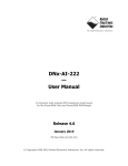
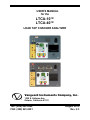
USER’S MANUAL
for the
LTCA-10™
LTCA-40™
LOAD TAP CHANGER ANALYZER
Vanguard Instruments Company, Inc.
1520 S. Hellman Ave.
Ontario, California 91761
TEL: (909) 923-9390
FAX: (909) 923-9391
August 2015
Rev. 2.3
LTCA-10/LTCA-40 USER’S MANUAL
SAFETY SUMMARY
NOTICE
This manual applies to both the LTCA-10 and LTCA-40. The operating procedures are virtually
the same for both models, and any differences are clearly described within the step-by-step
procedures.
FOLLOW EXACT OPERATING PROCEDURES
Any deviation from the procedures described in this User’s Manual may create one or more
safety hazards, may damage the LTCA-10/40, damage the test transformer, or cause errors in the
test results. Vanguard Instruments Company, Inc. assumes no liability for unsafe or improper use
of the LTCA-10/40.
All safety precautions provided in this manual must be observed during all phases of testing
including test preparation, test lead connection, actual testing, and test lead disconnection.
SAFETY WARNING AND CAUTIONS
The LTCA-10/40 shall be used only by trained operators. All transformers under test shall be
off-line and fully isolated.
DO NOT MODIFY TEST EQUIPMENT
To avoid the risk of introducing additional or unknown hazards, do not install substitute parts or
perform any unauthorized modification to any LTCA-10/40 test unit. To ensure that all designed
safety features are maintained, it is highly recommended that repairs be performed only by
Vanguard Instruments Company factory personnel or by an authorized repair service.
Unauthorized modifications can cause safety hazards and will void the manufacturer’s warranty.
WARNING
Do not remove test leads during a test. Failure to heed this warning can result in electrical shock
to personnel and damage to the equipment.
2
LTCA-10/LTCA-40 USER’S MANUAL
TABLE OF CONTENTS
CONVENTIONS USED IN THIS DOCUMENT .......................................................................... 5
1.0
INTRODUCTION ............................................................................................................... 6
1.1 General Description.......................................................................................................... 6
1.2 Functional Description ..................................................................................................... 6
1.3 Furnished Accessories ...................................................................................................... 7
2.0
TECHNICAL SPECIFICATIONS ...................................................................................... 8
2.1 LTCA-10 Technical Specifications .................................................................................. 8
2.2 LTCA-40 Technical Specifications .................................................................................. 9
3.0
CONTROLS AND INDICATORS.................................................................................... 10
3.1 LTCA-10 Controls and Indicators.................................................................................. 10
3.2 LTCA-40 Controls and Indicators.................................................................................. 12
4.0
PRE-TEST SETUP ............................................................................................................ 14
4.1 Operating Voltages ......................................................................................................... 14
4.2 LTCA-10/40 LCD Contrast Control .............................................................................. 14
4.3 LTCA-10/40 Printer Paper Control ................................................................................ 14
4.4 LTCA-10/40 Printer Paper ............................................................................................. 14
5.0
OPERATING PROCEDURES .......................................................................................... 15
5.1 Typical Connections to a Load Tap Changer (LTC)...................................................... 15
5.2 Cable Connections.......................................................................................................... 16
5.3 General Procedures ........................................................................................................ 19
5.4 Performing a Resistance Test ......................................................................................... 20
5.4.1. Resistance Test Result Printouts ............................................................................. 27
5.5 Performing a Special Resistance Test ............................................................................ 29
5.5.1. Special Resistance Test Result Printout .................................................................. 34
5.6 Performing a Dynamic LTC Test ................................................................................... 35
5.6.1. Dynamic LTC Test Result Printouts ....................................................................... 40
5.7 Diagnostic Mode ............................................................................................................ 42
5.8 Setup Menu .................................................................................................................... 44
5.8.1. Entering the Transformer ID ................................................................................... 44
5.8.2. Restoring a Test Record .......................................................................................... 47
5.8.3. Printing the Test-Record Directory ......................................................................... 50
5.8.4. Erasing a Test Record ............................................................................................. 52
5.8.5. Enabling the Computer Interface ............................................................................ 54
5.8.6. Setting the Date and Time....................................................................................... 55
5.8.7. Setting the Test Value Display Font ....................................................................... 56
6.0
LTCA-10/40 SPECIAL FEATURES ................................................................................ 57
6.1 Bypassing the Resistance Value Display Delay ............................................................. 57
6.2 Converting Resistance Measurements ........................................................................... 57
3
LTCA-10/LTCA-40 USER’S MANUAL
LIST OF FIGURES
Figure 1.0 LTCA-10 Controls and Indicators ............................................................................... 10
Figure 2.0 LTCA-40 Controls and Indicators ............................................................................... 12
Figure 3.0 Typical Connections to a Load Tap Changer (LTC) ................................................... 15
Figure 4.0 Typical LTCA-10/40 Connection Diagram (Dynamic Resistance Test) .................... 16
Figure 6.0 Typical LTCA-40 Connection Diagram (2 Windings) ............................................... 17
Figure 7.0 Typical LTCA-40 Connection Diagram (3 Windings) ............................................... 18
Figure 8.0 Typical Triple Reading Test Report Printout .............................................................. 27
Figure 9.0 Typical Dual Reading Test Report Printout ................................................................ 27
Figure 10.0 Typical Single Reading Test Report Printout............................................................ 28
Figure 11.0 Typical Single Reading Test Report Printout............................................................ 34
Figure 12.0 Sample Normal Dynamic LTC Test Plot .................................................................. 40
Figure 13.0 Sample Dynamic LTC Test Expansion Plot .............................................................. 41
Figure 14.0 Typical Test Record Printout..................................................................................... 49
Figure 15.0 Typical Record Directory Printout ............................................................................ 51
LIST OF TABLES
Table 1.0 LTCA-10 Specifications ................................................................................................. 8
Table 2.0 LTCA-40 Specifications ................................................................................................. 9
Table 3.0 Functional Descriptions of LTCA-10 Controls and Indicators .................................... 11
Table 4.0 Functional Descriptions of LTCA-40 Controls and Indicators .................................... 13
4
LT
TCA-10/LT
TCA-40 USER’S MANUAL
CONV
VENTIO
ONS USE
ED IN THIS
T
DO
OCUME
ENT
This docuument uses the
t following conventionns:
•
A keyy or switch on
o the LTCA
A-10/40 is inndicated as [KEY]
•
Menuu options aree referenced as (MENU OPTION)
O
•
Screeen and menu
u names are referenced
r
as “SCREEN
N/MENU NA
AME”
•
LTCA
A-10/40 LCD
D screen outtput is show
wn as:
1. OPTION 1
2. OPTION 2
3. OPTION 3
•
Warnning messagees are indicaated as:
Warning messsage
WAR
RNING
•
Impoortant notes are
a indicatedd as:
No
ote details
NO
OTE
5
LTCA-10/LTCA-40 USER’S MANUAL
1.0
INTRODUCTION
1.1
General Description
The Vanguard LTCA-10 and LTCA-40 are microprocessor-controlled winding resistance meters.
These devices are designed to accurately measure large transformer winding resistance, motor
winding resistance, or the resistance of large inductive devices. This manual addresses the
LTCA-10 and LTCA-40 as one device. Any differences between the LTCA-10 and LTCA-40 are
addressed separately.
The LTCA-10 uses a 60Vdc/10 Amperes Direct Current (DC) power supply while the LTCA-40
uses a 60VDC/40 Amperes DC power supply. Both devices are capable of reading winding
resistances ranging from 1 micro-ohm to 500 ohms. Three voltage sensing channels allow the
LTCA-10/40 to read three resistance values in the same test. To ensure operator safety, the
LTCA-10/40 automatically discharges the stored energy in the transformer at the end of each
test.
The LTCA-10/40 has one resistance reading channel (V1) dedicated for dynamic resistance
testing. The dynamic resistance test feature can be used to monitor the transformer LTC or
Voltage Regulator contact resistance while changing tap positions. A resistance plot shows the
transformer LTC contact and winding resistance and can be used to detect LTC/Voltage
Regulator contact problems.
The transformer LTC or Voltage Regulator AC motor current can also be monitored by the
LTCA-10/40 using an AC clamp on the current sensor. This feature can be used to monitor the
LTC motor “On-Time” at each tap change operation.
The LTCA-10/40 is rugged, portable, and easy to use, requiring little training for first-time users.
A 16-key membrane keypad is used to control the unit. The LTCA-10/40 features a back-lit LCD
screen (64 x 128 dot graphic) that is viewable in bright daylight as well as low-light conditions.
A built-in thermal printer can print results on 4.5-inch wide thermal paper.
The LTCA-10/40 can store 128 static test records (48 tests per record) and 11 dynamic resistance
test records in Flash EEPROM. Test records can be recalled locally or transferred to a PC via the
available interfaces (RS-232C port, USB port, USB Flash drive port). A built-in USB Flash drive
interface provides a convenient method for transferring test records to or from a USB Flash
drive. Test records can also be transferred directly to a PC via the RS-232C or USB interface
ports. If using a USB Flash drive, test records stored in the LTCA-10/40’s internal memory can
be transferred to the drive, and then the supplied PC software can be used to view the test records
stored on the drive. Up to 999 test records can be stored on a USB Flash drive.
1.2
Functional Description
The LTCA-10/40’s operation is based on the electrical relationship described by Ohm’s law:
R=V/I, where I is a known current and V is the DC voltage measured across the unknown
resistance. The value of the unknown resistance is calculated by dividing the measured voltage
by the current which is calculated by the microprocessor. Calculated resistance readings are then
displayed on the unit’s back-lit LCD screen.
A special current source allows the LTCA-10 to output 1, 5 and 10 Amperes of test current. The
LTCA-40 can output 1, 5, 10 or 40 Amperes of test current. For added safety, the current source
6
LTCA-10/LTCA-40 USER’S MANUAL
circuit is thermally protected. Also, a built-in discharge circuit automatically discharges the
stored energy in the transformer at the end of each test.
1.3
Furnished Accessories
The LTCA-10/40 is furnished with eight 50-foot test cables with “quick disconnect” type test
plugs on the unit end and battery-type clamps at the test load end. One power cord, one ground
cable, one current sense cable, one LTC operation cable and a cable-carrying bag is also
included.
7
LT
TCA-10/LT
TCA-40 USER’S MANUAL
2.0
T
TECHNICA
AL SPEC
CIFICATIO
ONS
2.1
L
LTCA-10
Te
echnical Sp
pecificatio
ons
T
Table
1.0 LTC
CA-10 Specifications
TYPE
PH
HYSICAL SPEC
CIFICATIONS
Load tap cha
anger analyzer
21”W x 9” H x 17”D (53 cm x 24 cm x 43 cm);
c
Weight: 33
3 lbs (15.4 kg)
OPERATIN
NG VOLTAGE
100 – 240 Va
ac, 50/60 Hz
RESISTANC
CE READING
RANGE
1 micro-ohm – 500 ohms
ACCURACY
1 – 19,999 micro-ohms:
m
±0..5% reading, ±1 count;
20 – 999 milli-ohms: ±1% re
eading, ±1 count;
1 – 500 ohmss: ±1.5% readin
ng, ±1 count
RESISTANCE
E CHANNELS Three static resistance
r
read
ding channels, One dynamic resistance channel
TES
ST VOLTAGE
60 Vdc max
TEST
T CURRENTS 1 ampere, 5 amperes,
a
10 amperes
AC CURR
RENT PROBE
Clamp-on current sensor, 1 – 20 Amperess, AEMC mode
el MN106
DISPLAY Back-lit LCD Screen (64 x 128
1 dot graphicc ); viewable in bright sunlightt and
els
low-light leve
PRINTER
EX
XTERNAL DAT
TA STORAGE
4.5-inch wide
e thermal printe
er
One USB Fla
ash drive interfa
ace port; storess up to 999 tesst records on a USB
Flash drive (n
not included)
COMPUTER IN
NTERFACES
One RS-232C
C port, One US
SB port
I
INTERNAL
TE
EST RECORD
STORAGE
Stores up to 128 static resisstance test reco
ords (48 tests per record) and
d 11
dynamic resisstance test reccords
LOAD TAP CHANGER 240 Vac, 1A
CONTACT
SAFETY
Designed to meet UL 61010
0A-1 and CAN//CSA C22.2 No
o. 1010.1-92
standards
EN
NVIRONMENT
Operating: -10˚C to 50˚ C (1
15˚F to +122˚ F);
F Storage: -30
0˚ C to 70˚ C (-22˚F to +158˚ F)
CABLES
One 50-foot current
c
cable set,
s Three 50-fo
oot resistance cable
c
sets, One
e
ground cable
e, One USB cab
ble, One RS-23
32C cable, One
e current sense
e
cable, One LTC control cab
ble, power cord, cable bag
OPTIONS Transportatio
on Case
WARRANTY
One year on parts and labo
or
The above
a
speciffications are valid at nom
minal operatiing voltage and
a at a
tempeerature of 255°C (77°F). Specificationns may channge without prior
p
notice.
NOT
TE
8
LT
TCA-10/LT
TCA-40 USER’S MANUAL
2.2
L
LTCA-40
Te
echnical Sp
pecificatio
ons
T
Table
2.0 LTC
CA-40 Specifications
TYPE
PH
HYSICAL SPEC
CIFICATIONS
Load tap cha
anger analyzer
25”W x 8.5”H
H x 20”D (63.5 cm
c x 21.6 cm x 50 cm); Weig
ght: 46 lbs (20 kg)
k
OPERATIN
NG VOLTAGE
100 – 240 Va
ac, 50/60 Hz
RESISTANC
CE READING
RANGE
1 micro-ohm – 500 ohms
ACCURACY
1 – 19,999 micro-ohms:
m
±0..5% reading, ±1 count;
20 – 999 milli-ohms: ±1% re
eading, ±1 count;
1 – 500 ohmss: ±1.5% readin
ng, ±1 count
RESISTANCE
E CHANNELS Three static resistance
r
read
ding channels, One dynamic resistance channel
TES
ST VOLTAGE
TEST
T CURRENTS
AC CURR
RENT PROBE
DISPLAY
60 Vdc max
1 ampere, 5 amperes,
a
10 amperes, 40 am
mperes
Clamp-on current sensor, 1 – 20 Amperess, AEMC mode
el MN106
Back-lit LCD Screen (64 x 128
1 dot graphicc ); viewable in bright sunlightt and
low-light leve
els
PRINTER 4.5-inch wide
e thermal printe
er
EX
XTERNAL DAT
TA STORAGE
One USB Fla
ash drive interfa
ace port; storess up to 999 tesst records on a USB
Flash drive (n
not included)
COMPUTER IN
NTERFACES
One RS-232C
C port, One US
SB port
I
INTERNAL
TE
EST RECORD
STORAGE
Stores up to 128 static resisstance test reco
ords (48 tests per record) and
d 11
dynamic resisstance test reccords
LOAD TAP CHANGER 240 Vac, 1A
CONTACT
SAFETY
EN
NVIRONMENT
CABLES
Designed to meet UL 61010
0A-1 and CAN//CSA C22.2 No
o. 1010.1-92
standards
Operating: -10˚C to 50˚ C (1
15˚F to +122˚ F);
F Storage: -30
0˚ C to 70˚ C (--22˚F
to +158˚ F)
One 50-foot current
c
cable set,
s Three 50-fo
oot resistance cable
c
sets, One
e
ground cable
e, One USB cab
ble, One RS-23
32C cable, One
e current sense
e
cable, One LTC control cab
ble, power cord, cable bag
OPTIONS Transportatio
on Case
WARRANTY
One year on parts and labo
or
The above
a
speciffications are valid at nom
minal operatiing voltage and
a at a
tempeerature of 255°C (77°F). Specificationns may channge without prior
p
notice.
NOT
TE
9
LTCA-10/LTCA-40 USER’S MANUAL
3.0
CONTROLS AND INDICATORS
3.1
LTCA-10 Controls and Indicators
The LTCA-10’s controls and indicators are shown in Figure 1.0 below. A leader line with an
index number points to each control and indicator, which is cross-referenced to a functional
description in Table 3.0. The table describes the function of each item on the control-panel. The
purpose of the controls and indicators may seem obvious, but users should become familiar with
them before using the LTCA-10/40. Accidental misuse of the controls will usually cause no
serious harm. Users should also be familiar with the safety summary found on the front page of
this User’s Manual.
Figure 1.0 LTCA-10 Controls and Indicators
10
LTCA-10/LTCA-40 USER’S MANUAL
Table 3.0 Functional Descriptions of LTCA-10 Controls and Indicators
Item
Number
Panel Markings
1
AC Current
2
USB
3
Flash Drive
Functional Description
Clamp-on AC current probe connector
USB Interface Port
USB Flash Drive Interface Port
4
None
5
120-240 7.5A, 50-60
Hz
Fuse: 250Vac, 1A
Fast-Blow
6
GROUND
7
None
Built in 4.5-inch wide thermal printer.
NOTE: For best printing results, it is recommended that only VIC thermal
paper be used
8
None
Liquid-Crystal Display, 64 x 128 dot graphic display. Back-lit and viewable in
bright sunlight and low-light conditions. Displays menus, user selections,
status readouts and test results
9
LTC Control
Load Tap Changer Control. Allows the user to change the Load Tap Changer
position using the RAISE and LOWER buttons
10
DISCHARGE
Red LED indicator light. When lit, this indicator warns the operator that the
LTCA-10 is discharging the stored energy in the transformer.
Do not disconnect test leads when this light is on. Failure to heed this
warning can result in shock to personnel
11
HIGH VOLTAGE
PRESENT
Red LED indicator light. Lights to warn operator that there is a possibility that
voltage exists across test leads.
Do not disconnect test leads when this light is on. Failure to heed this
warning can result in shock to personnel
12
None
Air Vents
Input power connector with third-wire safety ground, ON/OFF rocker toggle
switch with built-in fuse protection
5/16-18 threaded stud, with hand-turned wing nut, safety ground. This must be
connected to station ground before connecting LCTA-10 test leads to the
transformer
Membrane keypad, 10 alpha-numeric keys and 6 function keys (START,
STOP, CLEAR, ENTER, and CONTRAST/PAPER positioning UP and DOWN)
9-pin RS-232C interface port; female DB type. Data rate is set to 19,200 baud,
1 start bit, 2 stop bits, 8 data bits and no parity bit
Pin
Signal
13
RS-232C
14
V1, V2, V3,
CURRENT (I+, I-)
15
RAISE
16
LOWER
17
LTC CONTROL
2
RX
3
TX
5
Signal Ground
Voltage sensing input channels 1, 2, and 3. Female test connector jacks for
connecting test current output test leads
Fuse for the LTC Control Raise leads
Fuse for the LTC Control Lower leads
Load Tap Changer controller connector
11
LTCA-10/LTCA-40 USER’S MANUAL
3.2
LTCA-40 Controls and Indicators
The LTCA-40’s controls and indicators are shown in Figure 2.0 below. A leader line with an
index number points to each control and indicator, which is cross-referenced to a functional
description in Table 4.0. The table describes the function of each item on the control-panel. The
purpose of the controls and indicators may seem obvious, but users should become familiar with
them before using the LTCA-10/40. Accidental misuse of the controls will usually cause no
serious harm. Users should also be familiar with the safety summary found on the front page of
this User’s Manual.
Figure 2.0 LTCA-40 Controls and Indicators
12
LTCA-10/LTCA-40 USER’S MANUAL
Table 4.0 Functional Descriptions of LTCA-40 Controls and Indicators
Item
Number
Panel Markings
1
AC Current
2
USB
USB Interface port
3
None
The air intake cooling fans maintain the internal temperature. There are output
air fans on the sides of the case
4
120-240 7.5A, 50-60
Hz
Fuse: 250Vac, 1A
Fast-Blow
5
GROUND
6
Flash Drive
7
None
Built in 4.5-inch wide thermal printer.
NOTE: For best printing results, it is recommended that only VIC thermal paper
be used
8
None
Liquid-Crystal Display, 64 x 128 dot graphic display. Back-lit and viewable in
bright sunlight and low-light conditions. Displays menus, user selections, status
readouts and test results
9
LTC Control
Load Tap Changer Control. Allows the user to change the Load Tap Changer
position using the RAISE and LOWER buttons
10
DISCHARGE
Red LED indicator light. When lit, this indicator warns the operator that the
LTCA-40 is discharging the stored energy in the transformer.
Do not disconnect test leads when this light is on. Failure to heed this
warning can result in shock to personnel
11
HIGH VOLTAGE
PRESENT
Red LED indicator light. Lights to warn operator that there is a possibility that
voltage exists across test leads.
Do not disconnect test leads when this light is on. Failure to heed this
warning can result in shock to personnel
12
None
Functional Description
Clamp-on AC current probe connector
Input power connector with third-wire safety ground, ON/OFF rocker toggle
switch with built-in fuse protection
5/16-18 threaded stud, with hand-turned wing nut, safety ground. This must be
connected to station ground before connecting LCTA-40 test leads to the
transformer
USB Flash Drive Interface Port
Membrane keypad, 10 alpha-numeric keys and 6 function keys (START, STOP,
CLEAR, ENTER, and CONTRAST/PAPER positioning UP and DOWN)
9-pin RS-232C interface port; female DB type. Data rate is set to 19,200 baud,
1 start bit, 2 stop bits, 8 data bits and no parity bit
Pin
Signal
13
RS-232C
2
RX
3
TX
5
Signal Ground
14
V1, V2, V3,
CURRENT (I+, I-)
Voltage sensing input channels 1, 2, & 3. Female test connector jacks for
connecting test current output test leads
15
RAISE
Fuse for LTC Control Raise leads
16
LOWER
Fuse for LTC Control Lower leads
17
LTC CONTROL
Load Tap Changer controller connector
13
LTCA-10/LTCA-40 USER’S MANUAL
4.0
PRE-TEST SETUP
4.1
Operating Voltages
The LTCA-10/40’s operating voltages are 100-240 Vac and 50/60 Hz.
4.2
LTCA-10/40 LCD Contrast Control
To increase the LCD screen contrast, press and hold the [PAPER ∧ Contrast] key for two
seconds.
To decrease the LCD screen contrast, press and hold the [PAPER ∨ Contrast] key for two
seconds.
4.3
LTCA-10/40 Printer Paper Control
To advance the LTCA-10/40 printer paper, press and release the [PAPER ∧ Contrast] key.
To retract the LTCA-10/40 printer paper, press and release the [PAPER ∨ Contrast] key.
4.4
LTCA-10/40 Printer Paper
The LTCA-10/40’s built-in thermal printer uses 4.5-inch wide thermal paper for printing test
results. To maintain the highest print quality and to avoid paper jams, the use of thermal paper
supplied by Vanguard Instruments Company is highly recommended. Additional paper can be
ordered from the following sources:
Vanguard Instruments Co, Inc.
1520 S. Hellman Avenue
Ontario, CA 91761
Tel: 909-923-9390
Fax: 909-923-9391
Part Number: VIC TP-4 paper
BG Instrument Co.
13607 E. Trent Avenue
Spokane, WA 99216
Tel: 509-893-9881
Fax: 509-893-9803
Part Number: VIC TP-4 paper
14
LTCA-10/LTCA-40 USER’S MANUAL
5.0
OPERATING PROCEDURES
The LTCA-10/40 is simple to operate and only requires the selection of choices from display
menus and responding to displayed prompts. However, first-time operators should review the
following operating procedures to become familiar with all LTCA-10/40 operations and the
logical branching for various test options. More experienced operators may use these procedures
as a handy help and reference guide.
5.1
Typical Connections to a Load Tap Changer (LTC)
Figure 3.0 Typical Connections to a Load Tap Changer (LTC)
15
LT
TCA-10/LT
TCA-40 USER’S MANUAL
5.2
C
Cable
Conn
nections
WARNIING
Do no
ot touch or disconnect any test leaad that is connnected to a transformer
termiinal while high current iss being condducted durin
ng a test. Faiilure to heedd this
warniing can result in electriccal shock to personnel annd/or damagge to the
equip
pment.
Figure 4.0 Typical
T
LTCA
A-10/40 Conn
nection Diag
gram (Dynam
mic Resistanc
ce Test)
Afterr discharge, always
a
discoonnect test clips
c
slowly from transfo
former bushinngs
to preevent an acciidental flashh-over.
WARNIING
16
LTCA-10/LTCA-40 USER’S MANUAL
Figure 5.0 Typical LTCA-40 Connection Diagram (2 Windings)
17
LTCA-10/LTCA-40 USER’S MANUAL
Figure 6.0 Typical LTCA-40 Connection Diagram (3 Windings)
18
LT
TCA-10/LT
TCA-40 USER’S MANUAL
5.3
G
General
Pro
ocedures
a. Ground
G
the LTCA-10/40
L
to substation ground (Ittem 6 in Figuure 1.0, Item
m 5 in figure 2.0).
Always
A
connnect the LTC
CA-10/40 to the substatioon ground beefore conneccting
test
t leads to any transforrmer bushingg. Failure to follow this procedure
p
m
may
damage
d
the
L
LTCA-10/40
0.
W
WARNING
b. Plug the LTC
CA-10/40 pow
wer cable innto a power outlet.
o
c. Innsert currentt-cable plugss and voltagee-sensing cabble plugs intto their respeective controol
panel jacks.
d. A
Attach test-caable clamps to the transfformer terminals for the winding thatt is to be
m
measured.
e. Turn
T
on the LTCA-10/40
L
0 power by pressing
p
[I] on
o the rockerr switch.
f. O
Once the pow
wer is turned on, the unitt will perform
m self-calibrration and display a few startupp messages. Once the shhort start-up sequence is completed, the “START
T-UP” menuu will
be displayed (date and tim
me will obviously be diffferent):
1. TEST XFMR
2. SETUP
3. USER DIAG
03/04/0
09
09:28:0
03
19
LTCA-10/LTCA-40 USER’S MANUAL
5.4
Performing a Resistance Test
a. Start from the “START-UP” menu:
1. TEST XFMR
2. SETUP
3. USER DIAG
03/04/09
09:28:03
Press the [1] key (TEST XFMR) to start a test.
b. The following menu will be displayed:
1. RESISTANCE TEST
2. SPECIAL RESISTANCE TEST
3. DYNAMIC LTC TEST
Press the [1] key (RESISTANCE TEST) to start a resistance test.
c. The following menu will be displayed:
1. V1, V2, V3 RES TEST
2. V1, V2
RES TEST
3. V1 ONLY
RES TEST
Select the number of channels that will be used to measure resistance by pressing the
corresponding numeric key ([1], [2], or [3]).
d. The “SELECT TEST CURRENT” menu will be displayed:
SELECT TEST CURRENT:
1. 1 AMP
2. 5 AMPS
3. 10 AMPS
SELECT TEST CURRENT:
1. 1 AMP
2. 5 AMPS
3. 10 AMPS
4. 40 AMPS
LTCA-10
LTCA-40
Select the test current by pressing the [1], [2], [3] , or [4] (LTCA-40 only) key.
e. The “CONVERT READINGS TO STANDARD TEMP?” menu will be displayed as
shown below:
CONVERT READINGS TO
STANDARD TEMP?
1. YES
2. NO
1. YES
If you wish to convert readings to standard temperature, press the [1] key (YES).
The “WINDING MATERIAL” menu will be displayed:
WINDING MATERIAL
1. COPPER, Tk=234.5
2. ALUMINUM, Tk=225.0
3. MANUALLY ENTER Tk
20
LT
TCA-10/LT
TCA-40 USER’S MANUAL
a. Press the [1]
[ key to seelect copper as the windiing material.. Continue to
t
step f.
b. Press the [2]
[ key to seelect aluminu
um as the wiinding materrial. Continu
ue to
step f.
c. Press the [3]
[ key to manually
m
enteer the Tk vallue. The following screen
will be dissplayed:
Tk:
230.0°C
↑↓ to adjust Tk
T
“ENTER
R” to acc
cept
You can inncrease the Tk
T value by 0.5°C increm
ments by preessing the
[PAPER ∧ Contrast] key. You can decreasse the Tk vallue by 0.5°C
C
incrementss by pressingg the [PAPE
ER ∨ Contrrast] key. Press
P
the
[ENTER]] key to conffirm your tem
mperature seelection. Con
ntinue to steep f.
2. NO
If you
u do NOT wiish to converrt readings to standard teemperature, press the [2
2]
key (N
NO) and con
ntinue to steep h.
f. After
A
the Tk value
v
has beeen selected, the “D.U.T. TEMP” scrreen will be displayed:
D.U.T.
D
TEMP
25.
.0°C
7
77.0°F
djust tem
mp
↑↓ to ad
“ENTER” to accep
pt
Use the [PAP
U
PER ∧ Con
ntrast] and [PAPER ∨ Contrast]] keys to adjjust the D.U..T.
teemperature. Press the [E
ENTER] key
y to confirm the temperaature selectioon.
D.U
U.T is short for Device Under
U
Test
NOTE
g. The
T “REFER
RENCE TEM
MP” screen will
w be displaayed:
REF
FERENCE TEMP:
85.
.0°C
18
85.0°F
↑↓ to ad
djust tem
mp
“ENTER” to accep
pt
Use the [PAP
U
PER ∧ Con
ntrast] and [PAPER ∨ Contrast]] keys to adjjust the
R
Reference
Teemperature. Press
P
the [EN
NTER] key
y to confirm the
t temperatture selectionn.
21
TCA-10/LT
TCA-40 USER’S MANUAL
LT
Thee LTCA-10//40 will calcuulate the equuivalent resistance valuee at this new
tem
mperature.
NOTE
h. The
T following
g “WARNIN
NG” screen will
w be displlayed:
********
**WARNING*********
DANGE
EROUS FLA
ASH-OVER
WILL OCCUR IF
F CABLES
ARE DISCONNECTED!
******************
********
This warning reminds thee operator thhat the next sequence
T
s
of test
t steps wiill run currennt
thhrough the teest load.
Press the [EN
NTER] key to
t proceed too the next steep.
i. O
One of the following mennus will be displayed
d
(w
with the relevvant test current value)
depending on
n how many channels weere selected in
i step c.
-V
V1 TEST ONLYO
1 AMP TE
EST
-V1 & V2 TES
STT
1 AMP TEST
“STAR
RT” TO RUN TEST
OR
“ST
TOP” TO ABORT
“START” TO RUN TEST
OR
“STOP” TO ABORT
V Test Only
V1
V1 & V2 Test
-V1, V2, & V3 TESTEST
1 AMP TE
“STAR
RT” TO RUN TEST
OR
“ST
TOP” TO ABORT
V V2, & V3 Test
V1,
T
Iff you have made
m
any erroors or wouldd like to aborrt the test, prress the [ST
TOP] key, an
nd
you will be reeturned to thhe “START-U
UP” menu.
Press the [ST
TART] key to
t run the tesst. The follow
wing screenn will be dispplayed
m
momentarily:
:
CALIBRAT
C
ING
PLEASE
P
WA
AIT…
22
TCA-10/LT
TCA-40 USER’S MANUAL
LT
After the LTC
A
CA-10/40 finnishes its intternal calibraation, the “X
XFMR CHAR
RGING” scrreen
w be displaayed:
will
XF
FMR CHARGING
PL
LEASE WAI
IT...
* XFM
MR ENERGIZED! *
This is only an
T
a informatioonal screen to
t remind thee operator thhat a test is inn progress. The
T
display duratiion of this message
m
depeends on the size
s of the winding’s
w
indductance andd the
teest current seelected.
Yo
ou can bypass this delay and observe the resistannce value imm
mediately. See
S
secction 6.1 for instructions on how to select
s
this opption.
NOTE
j. T
The LTCA-10
0/40 determines when thhe resistancee reading is stable
s
and diisplays the
reesistance vallues on the LCD
L
screen as
a follows:
I
R1
R2
*
TES
ST IN PRO
OGRESS
= 1.09 AMPS
= 7.272 mΩ
Ω
= 358μΩ
XFM
MR ENERGIZED! *
The LTCA-10
T
0/40 will conntinue the teest and updatte the resistaance values on
o the LCD
sccreen. Whilee the test is in progress, the
t [ENTER
R] key can be
b pressed to save the currrent
reeading on the LCD to the LTCA-10//40’s internaal working memory.
m
This feature is
T
i very conveenient for stooring multipple readings during
d
a testt. A typical
exxample of th
his applicatioon is an LTC
C or Voltage Regulator contact
c
resisttance test whhere
m
multiple
read
dings are requuired. For exxample, the user
u can starrt the test at one tap posiition,
annd when thee reading is stable,
s
press the [ENTER
R] key to sav
ve the readinng. Then, thee
user can chan
nge the tap position and save
s
the stabble reading at
a the new taap position byy
[
keey. This proccess can be repeated
r
as needed
n
for a maximum of
o 48
prressing the [ENTER]
tiimes per testt record.
Iff the [ENTE
ER] key is prressed, the data
d is saved and the SAV
VING TEST
T message will
w be
displayed on the LCD as shown below
w:
TES
ST IN PRO
OGRESS
====> SAVING
S
TEST <====
I = 1.09 AMPS
R1 = 7.272 mΩ
Ω
R2 = 358μΩ
* XFM
MR ENERGIZED! *
23
LTCA-10/LTCA-40 USER’S MANUAL
Once the data is saved, the TEST SAVED message will be displayed:
TEST IN PROGRESS
====> TEST SAVED! <====
I = 1.09 AMPS
R1 = 7.272 mΩ
R2 = 358μΩ
* XFMR ENERGIZED! *
k. Press the [STOP] key to stop running the test. Press the [STOP] key a second time to
continue to the next step.
l. The “PRINT TEST RESULTS?” menu will be displayed:
PRINT TEST RESULTS?
1. YES
2. NO
1. YES
Press the [1] key (YES) to print the test results on the built-in thermal printer. The
last test results displayed on the LCD screen will be printed. Typical LTCA-10/40
test reports are shown in Figure 7.0, Figure 8.0, and Figure 9.0. Continue to step
m.
2. NO
Press the [2] key (NO) to bypass the printing of the test results. Continue to step
m.
m. The “KEEP THIS READING?” menu will be displayed:
KEEP THIS READING?
1. YES
2. NO
1. YES
If you wish to save the reading, press the [1] key (YES). One of the following
screens will be displayed:
The following screen will be displayed if there is no previous data in the memory:
=====> TEST SAVED! <=====
24
TCA-10/LT
TCA-40 USER’S MANUAL
LT
The fo
ollowing scrreen will be displayed
d
if previous datta for the sam
me test type is
stored
d in the mem
mory:
PRE
EVIOUS DA
ATA IN BU
UF?
03/
/01/09
10:30
1. APPEND PREV DATA
A?
2. CLEAR PREV DATA
The LTCA-10/40
L
retains the current
c
test results
r
in its working meemory. Whenn a
test is finished, the user can apppend the neew test resullts to the prevvious test reesults
in the working meemory, as lonng as the unit’s power has not been turned
t
off
betweeen tests.
If dataa exists in thhe working memory,
m
youu will be pressented with the “PREVIIOUS
DATA
A IN BUF?”” menu show
wn above. Preess the [1] key
k to appennd the currennt test
resultss to the prevvious test ressults in the working
w
mem
mory. Press thhe [2] key too
only save
s
the currrent test resuults and discaard any prevvious data froom the workking
memo
ory.
In eith
her case, preess the [ENT
TER] key an
nd continue to
t step n.
2. NO
If you
u do not wishh to save thee reading, preess the [2] key
k (NO) andd continue to
t
step n.
n
n. The
T “RUN ANOTHER
A
T
TEST?”
mennu will be dissplayed:
RUN ANOT
THER TEST
T?
1. YES
2. NO
1. YES
If you
u would like to run anothher test, press the [1] keyy (YES) and return to sttep
c.
2. NO
If you
u do not wishh to run anotther test, press the [2] keey (NO) andd continue too
step o.
o
o. The
T “SAVE THIS
T
RECO
ORD?” menuu will be dispplayed:
SAVE THI
IS RECORD
D?
1. YES
2. NO
Thee test recordd must be savved to Flash EEPROM so
s that it can be recalled and
prin
nted at a lateer time.
NOTE
25
TCA-10/LT
TCA-40 USER’S MANUAL
LT
1. YES
u wish to savve the recordd, press the [1] key (YESS) and contin
nue to step p.
p
If you
2. NO
u do not wishh to save thee record, presss the [2] keey (NO). Thee following
If you
messaage will be displayed:
d
ARE
E YOU SUR
RE?
DAT
TE WILL BE
B LOST!
1. DO NOT SAVE RECO
ORD
2. SAVE RECORD
Press the [1] key (DO NOT SAVE
SA RECOR
RD) if you do
d not want to
t save the
record
d. You will be
b returned to
t the “STAR
RT-UP” mennu.
Press the [2] key (SAVE REC
CORD) to savve the recordd. Continue to step p.
p. The
T following
g message will
w be displaayed:
RECORD NUMBER
N
01
1
HAS BEE
EN SAVED!
Thee record num
mber is autom
matically asssigned and inncremented by the LTCA
A10//40.
NOTE
Press the [EN
NTER] key to
t return to the
t “START
T-UP” menu..
26
LTCA-10/LTCA-40 USER’S MANUAL
5.4.1. Resistance Test Result Printouts
Figure 7.0 Typical Triple Reading Test Report Printout
Figure 8.0 Typical Dual Reading Test Report Printout
27
LTCA-10/LTCA-40 USER’S MANUAL
Figure 9.0 Typical Single Reading Test Report Printout
28
LTCA-10/LTCA-40 USER’S MANUAL
5.5
Performing a Special Resistance Test
The Special Resistance Test is used to conduct a resistance test for a pre-defined period ranging
from 1 to 45 minutes. The resistance data is recorded at 1 minute intervals. Use the following
procedures to perform a Special Resistance Test.
a. Start from the “START-UP” menu:
1. TEST XFMR
2. SETUP
3. USER DIAG
03/04/09
09:28:03
Press the [1] key (TEST XFMR) to start a test.
b. The following menu will be displayed:
1. RESISTANCE TEST
2. SPECIAL RESISTANCE TEST
3. DYNAMIC LTC TEST
Press the [2] key (SPECIAL RESISTANCE TEST) to start a special resistance test.
c. The following menu will be displayed:
1. V1, V2, V3 SPEC TEST
2. V1, V2
SPEC TEST
3. V1 ONLY
SPEC TEST
Select the number of channels by pressing the corresponding key ([1], [2], or [3])
d. The “ENTER SPECIAL TEST TIME MINUTES” screen will be displayed:
ENTER SPECIAL TEST
TIME MINUTES (1-45):
10
Enter the test time (between 1-45 minutes) using the keypad on the LTCA-10/40 and then
press the [ENTER] key. Ten (10) minutes is used for the test time in this example.
e. The “SELECT TEST CURRENT” menu will be displayed:
SELECT TEST CURRENT:
1. 1 AMP
2. 5 AMPS
3. 10 AMPS
SELECT TEST CURRENT:
1. 1 AMP
2. 5 AMPS
3. 10 AMPS
4. 40 AMPS
LTCA-10
LTCA-40
Select the test current by pressing the [1], [2], [3] , or [4] (LTCA-40 only) key.
f. The “CONVERT READINGS TO STANDARD TEMP?” menu will be displayed:
CONVERT READINGS TO
STANDARD TEMP?
1. YES
2. NO
29
LTCA-10/LTCA-40 USER’S MANUAL
1. YES
If you wish to convert readings to standard temperature, press the [1] key (YES).
The “WINDING MATERIAL” menu will be displayed:
WINDING MATERIAL
1. COPPER, Tk=234.5
2. ALUMINUM, Tk=225.0
3. MANUALLY ENTER Tk
a. Press the [1] key to select copper as the winding material. Continue to
step g.
b. Press the [2] key to select aluminum as the winding material. Continue to
step g.
c. Press the [3] key to manually enter the Tk value. The following screen
will be displayed:
Tk:
230.0°C
↑↓ to adjust Tk
“ENTER” to accept
You can increase the Tk value by 0.5°C increments by pressing the
[PAPER ∧ Contrast] key.
You can decrease the Tk value by 0.5°C increments by pressing the
[PAPER ∨ Contrast] key.
Press the [ENTER] key to confirm your temperature selection. Continue
to step g.
2. NO
If you do NOT wish to convert readings to standard temperature, press the [2]
key (NO) and continue to step i.
g. After the Tk value has been selected, the “D.U.T. TEMP” screen will be displayed:
D.U.T. TEMP
25.0°C
77.0°F
↑↓ to adjust temp
“ENTER” to accept
Use the [PAPER ∧ Contrast] and [PAPER ∨ Contrast] keys to adjust the D.U.T.
temperature.
Press the [ENTER] key to confirm the temperature selection.
30
TCA-10/LT
TCA-40 USER’S MANUAL
LT
h. The
T “REFER
RENCE TEM
MP” screen will
w be displaayed:
REF
FERENCE TEMP:
85.
.0°C
18
85.0°F
↑↓ to ad
djust tem
mp
“ENTER” to accep
pt
Use the [PAP
U
PER ∧ Con
ntrast] and [PAPER ∨ Contrast]] keys to adjjust the
R
Reference
Teemperature. Press
P
the [EN
NTER] key
y to confirm the
t temperatture selectionn.
Thee LTCA-10//40 will calcuulate the equuivalent resistance valuee at this new
tem
mperature.
NOTE
i. The
T following
g “WARNIN
NG” screen will
w be displlayed:
********
**WARNING*********
DANGE
EROUS FLA
ASH-OVER
WILL OCCUR IF
F CABLES
ARE DISCONNECTED!
********
******************
This warning reminds thee operator thhat the next sequence
T
s
of test
t steps wiill run currennt
thhrough the teest load. Press the [ENT
TER] key to proceed to the
t next stepp.
j. O
One of the following mennus will be displayed
d
(w
with the relevvant test current value)
depending on
n how many channels weere selected in
i step c.
-V
V1 TEST ONLYO
1 AMP TE
EST
-V1 & V2 TES
ST1 AMP TEST
T
“STAR
RT” TO RUN TEST
OR
“ST
TOP” TO ABORT
“START” TO RUN TEST
OR
“STOP” TO ABORT
V Test Only
V1
V1 & V2 Test
-V1, V2, & V3 TEST1 AMP TE
EST
“STAR
RT” TO RUN TEST
OR
“ST
TOP” TO ABORT
V V2, & V3 Test
V1,
T
Iff you have made
m
any erroors or wouldd like to aborrt the test, prress the [ST
TOP] key, an
nd
you will be reeturned to thhe “START-U
UP” menu.
31
TCA-10/LT
TCA-40 USER’S MANUAL
LT
Press the [ST
TART] key to
t run the tesst. The follow
wing screenn will be dispplayed
m
momentarily:
:
CALIBRAT
C
ING
PLEASE
P
WA
AIT…
After the LTC
A
CA-10/40 finnishes its intternal calibraation, the “X
XFMR CHAR
RGING” scrreen
w be displaayed:
will
XF
FMR CHARGING
PL
LEASE WAI
IT...
* XFM
MR ENERGIZED! *
This is only an
T
a informatioonal screen to
t remind thee operator thhat a test is inn progress. The
T
display duratiion of this message
m
depeends on the size
s of the winding’s
w
indductance andd the
teest current seelected.
Yo
ou can bypass this delay and observe the resistannce value imm
mediately. See
S
secction 6.1 for instructions on how to select
s
this opption.
NOTE
k. T
The LTCA-10
0/40 determines when thhe resistancee reading is stable
s
and shhows the
reesistance vallue on the LC
CD as follow
ws (the first line shows the remaining test time):
REMAININ
NG TIME=1
10:00
I = 1.09 AMPS
R1 = 7.272 mΩ
Ω
* XFM
MR ENERGIZED! *
When the pree-defined test time has ellapsed, the “TEST
W
“
RESU
ULTS” screeen will be
displayed:
TEST RES
SULTS
I = 1.09 AMPS
R1 = 7.285 mΩ
Ω
Thee number off resistance values
v
shownn will depennd on the num
mber of channnels
cho
osen in step c.
NOTE
Press the [EN
NTER] key.
T “SAVE THIS
T
RECO
ORD?” menuu will be dispplayed:
l. The
SAVE THI
IS RECORD
D?
1. YES
2. NO
32
TCA-10/LT
TCA-40 USER’S MANUAL
LT
Thee test recordd must be savved to Flash EEPROM so
s that it can be recalled and
prin
nted at a lateer time.
NOTE
1. YES
If you
u wish to savve the recordd, press the [1] key (YESS) and contin
nue to step m.
m
2. NO
If you
u do not wishh to save thee record, presss the [2] keey (NO). Thee following
messaage will be displayed:
d
ARE
E YOU SUR
RE?
DAT
TE WILL BE
B LOST!
1. DO NOT SAVE RECO
ORD
2. SAVE RECORD
Press the [1] key (DO NOT SAVE
SA RECOR
RD) if you do
d not want to
t save the
record
d. You will be
b returned to
t the “STAR
RT-UP” mennu.
Press the [2] key (SAVE REC
CORD) to savve the recordd. Continue to step m.
m. The
T following
g message will
w be displaayed:
RECORD NUMBER
N
01
1
HAS BEE
EN SAVED!
Thee record num
mber is autom
matically asssigned and inncremented by the LTCA
A10//40.
NOTE
Press the [EN
NTER] key to
t return to the
t “START
T-UP” menu..
33
LTCA-10/LTCA-40 USER’S MANUAL
5.5.1. Special Resistance Test Result Printout
Figure 10.0 Typical Single Reading Test Report Printout
34
LTCA-10/LTCA-40 USER’S MANUAL
5.6
Performing a Dynamic LTC Test
The Dynamic LTC Test is used to conduct a resistance test while the LTC or Regulator is
switching taps. The test time can be selected for a period from 15 to 240 seconds to allow the
LTC or Regulator enough time to switch through all of its taps during the test. The resistance
data is recorded continuously during the test period. The AC current probe can be clamped
around one of the motor leads to monitor the motor current during the test. Use the following
steps to perform a Dynamic LTC Test.
a. Start from the “START-UP” menu:
1. TEST XFMR
2. SETUP
3. USER DIAG
03/04/09
09:28:03
Press the [1] key (TEST XFMR) to start a test.
b. The following menu will be displayed:
1. RESISTANCE TEST
2. SPECIAL RESISTANCE TEST
3. DYNAMIC LTC TEST
Press the [3] key (DYNAMIC LTC TEST) to start a dynamic LTC test.
c. The following menu will be displayed:
SELECT SHOT TIME
1. 15 SECONDS
2. 30 SECONDS
3. 60 SECONDS
4. 120 SECONDS
5. 240 SECONDS
Select the shot time by pressing the corresponding key on the LTCA-10/40’s keypad
([1], [2], [3], [4], or [5])
d. The “SELECT TEST CURRENT” menu will be displayed as shown below. The LTCA10 offers a selection of 5 or 10 Amps while the LTCA-10 offers a selection of 10 or 40
AMPS.
SELECT TEST CURRENT:
1. 5 AMPS
2. 10 AMPS
SELECT TEST CURRENT:
1. 10 AMPS
2. 40 AMPS
LTCA-10
LTCA-40
Select the test current by pressing the corresponding key on the LTCA-10/40’s keypad
([1] or [2]).
35
LTCA-10/LTCA-40 USER’S MANUAL
e. The following “WARNING” screen will be displayed:
*********WARNING*********
DANGEROUS FLASH-OVER
WILL OCCUR IF CABLES
ARE DISCONNECTED!
*************************
This warning reminds the operator that the next sequence of test steps will run current
through the test load.
Press the [ENTER] key to proceed to the next step.
f. The “LTC TEST” screen will be displayed (with the relevant test current value selected
in step d):
LTC TEST
10 AMP TEST
“START” TO RUN TEST
OR
“STOP” TO ABORT
If you have made any errors or would like to abort the test, press the [STOP] key, and
you will be returned to the “START-UP” menu.
Press the [START] key to run the test. The following screen will be displayed
momentarily:
CALIBRATING
PLEASE WAIT…
After the LTCA-10/40 finishes its internal calibration, the “XFMR CHARGING” screen
will be displayed:
XFMR CHARGING
PLEASE WAIT...
* XFMR ENERGIZED! *
This is only an informational screen to remind the operator that a test is in progress. The
display duration of this message depends on the size of the winding’s inductance and the
test current selected.
g. The LTCA-10/40 determines when the resistance reading is stable and displays the
“READY TO CAPTURE DATA” screen:
READY TO CAPTURE DATA
PRESS “ENTER”
OR
LTC RAISE/LOWER
TO START TIMING
* XFMR ENERGIZED! *
36
LTCA-10/LTCA-40 USER’S MANUAL
Press the [ENTER] key to start capturing data for the time period selected in step e. The
LTC must be manually started to begin switching through the taps.
If the LTC cable is connected, then pressing the [LTC RAISE] key when cycling from
lower to higher taps or pressing the [LTC LOWER] key when cycling from higher to
lower taps will start capturing data.
The following screen will be displayed indicating that the test is in progress:
RUNNING DYNAMIC
LTC TEST
T = 15
R1 = 7.369 mΩ
“STOP” KEY TO ABORT
* XFMR ENERGIZED! *
h. When the pre-defined test time has elapsed or the [STOP] key is pressed, the “PRINT
TEST RESULTS?” menu will be displayed:
PRINT TEST RESULTS?
1. YES
2. NO
1. YES
Press the [1] key (YES) to print the test results on the built-in thermal printer. The
following menu will be displayed:
SELECT PLOT TYPE:
1. NORMAL PLOT
2. EXPANDED PLOT
1. NORMAL PLOT
Press the [1] key (NORMAL PLOT) to print a normal plot. The printer will
begin to print. A typical normal (full-scale) plot is shown in figure 11.0.
Continue to step i.
2. EXPANDED PLOT
To print an expanded plot, press the [2] key (EXPANDED PLOT).
Continue to step i.
2. NO
Press the [2] key (NO) to bypass the printing of the test results. Continue to step
j.
37
LTCA-10/LTCA-40 USER’S MANUAL
i. The “PRINT AN EXPANSION PLOT” menu will be displayed:
PRINT AN EXPANSION
PLOT?
1. YES
2. NO
1. YES
An expansion plot graphs the resistance waveform in more detail by allowing the
selection of a timeframe to be plotted using an appropriate resistance scale. Press
the [1] key (YES) to print an expansion plot. The following menu will be
displayed:
1. EXPANDED TIME & RES
2. EXPANDED RES ONLY
Press the corresponding key ([1] or [2]) to select the expansion type. The
“EXPANSION PRINT” menu will be displayed:
EXPANSION PRINT
START TIME: 0 S
END TIME:
0 S
Enter the START time and press the [ENTER] key. Enter the END time and
press the [ENTER] key. The “RESISTANCE PLOT RANGE” menu will be
displayed:
RESISTANCE PLOT RANGE
1. FULL RANGE
2. 100μΩ - 10mΩ
3. 1mΩ - 100mΩ
4. 10mΩ - 1Ω
5. 100mΩ - 10Ω
6. 1Ω - 100Ω
Select the resistance plot range by pressing the corresponding key on the LTCA10/40’s keypad ([1], [2], [3], [4], [5], or [6]). The printer will begin the print the
expansion plot. A time expansion plot from 17.0 seconds to 18.00 seconds and
resistance scale from 100 milli-ohms to 10 ohms is shown in figure 12.0.
When printing is completed, you will be returned to the “PRINT AN
EXPANSION PLOT?” menu and offered the option to print another expansion.
Return to step i.
2. NO
Press the [2] key (NO) if you do not wish to print an expansion. Continue to step
j.
38
TCA-10/LT
TCA-40 USER’S MANUAL
LT
j. The
T “SAVE THIS
T
RECO
ORD?” menuu will be dispplayed:
SAVE THI
IS RECORD
D?
1. YES
2. NO
Thee test recordd must be savved to Flash EEPROM so
s that it can be recalled and
prin
nted at a lateer time.
NOTE
1. YES
If you
u wish to savve the recordd, press the [1] key (YESS) and contin
nue to step k.
k
2. NO
If you
u do not wishh to save thee record, presss the [2] keey (NO). Thee following
messaage will be displayed:
d
ARE
E YOU SUR
RE?
DAT
TE WILL BE
B LOST!
1. DO NOT SAVE RECO
ORD
2. SAVE RECORD
Press the [1] key (DO NOT SAVE
SA RECOR
RD) if you do
d not want to
t save the
record
d. You will be
b returned to
t the “STAR
RT-UP” mennu.
Press the [2] key (SAVE REC
CORD) to savve the recordd. Continue to step k.
k. The
T following
g message will
w be displaayed:
RECORD NUMBER
N
01
1
HAS BEE
EN SAVED!
Thee record num
mber is autom
matically asssigned and inncremented by the LTCA
A10//40.
NOTE
Press the [EN
NTER] key to
t return to the
t “START
T-UP” menu..
39
LTCA-10/LTCA-40 USER’S MANUAL
5.6.1. Dynamic LTC Test Result Printouts
Figure 11.0 Sample Normal Dynamic LTC Test Plot
40
LTCA-10/LTCA-40 USER’S MANUAL
Figure 12.0 Sample Dynamic LTC Test Expansion Plot
41
LTCA-10/LTCA-40 USER’S MANUAL
5.7
Diagnostic Mode
In diagnostic mode, the LTCA-10/40 can run a resistance test, display the sense voltages, and
test current on the LTCA. This feature can be used to verify the LTCA-10/40’s voltage and
current readings against an external meter. Use the steps below to initiate a diagnostic test.
a. Start from the “START-UP” menu:
1. TEST XFMR
2. SETUP
3. USER DIAG
03/04/09
09:28:03
Press the [3] key (USER DIAG).
b. The “SELECT TEST CURRENT” menu will be displayed:
SELECT TEST CURRENT:
1. 1 AMP
2. 5 AMPS
3. 10 AMPS
SELECT TEST CURRENT:
1. 1 AMP
2. 5 AMPS
3. 10 AMPS
4. 40 AMPS
LTCA-10
LTCA-40
Select the test current by pressing the [1], [2], [3] , or [4] (LTCA-40 only) key.
c. The following “WARNING” screen will be displayed:
*********WARNING*********
DANGEROUS FLASH-OVER
WILL OCCUR IF CABLES
ARE DISCONNECTED!
*************************
This warning reminds the operator that the next sequence of test steps will run current
through the test load.
Press the [ENTER] key to proceed to the next step.
d. The following screen will be displayed:
-USER DIAG TEST“START” TO RUN TEST
OR
“STOP” TO ABORT
If you wish to abort the diagnostic test, press the [STOP] key, and you will be returned
to the “START-UP” menu.
Press the [START] key to run the diagnostic test.
42
LTCA-10/LTCA-40 USER’S MANUAL
e. The V1, V2, and V3 test currents will be displayed as shown below:
V1
V2
V3
I
=
=
=
=
07.53mV
08.23mV
09.12mV
01.091A
Press the [STOP] key to end the diagnostic test and return to the “START-UP” menu.
43
LT
TCA-10/LT
TCA-40 USER’S MANUAL
5.8
S
Setup
Menu
u
The setupp menu is ussed to configgure the LTC
CA-10/40 annd to also reccall and printt stored test
records. This
T section
n outlines thee procedures for accessinng and usingg the Setup Menu
M
optionss.
5.8.1. Entering
E
the Transforrmer ID
Transform
mer informaation can be entered usinng the steps outlined
o
beloow.
NO
OTE
Tesst identificattion data is entered
e
usingg the LTCA--10/40’s alphha-numeric
key
ypad. Keys are
a pressed for
f each charracter positioon (marked by
b the cursor) in
thee identificatioon area. Forr example, pressing the [2]
[ key oncee selects the
num
mber “2”. Prressing it a second time selects
s
the leetter “A”. A third press
seleects the letteer “B”. Presssing the key a fourth tim
me selects thee letter “C”.
Preessing the keey one more time restartss the cycle at
a the numberr “2”.
Thee characters selected aree entered at the
t position of
o the cursorr. Pressing thhe
[PA
APER ∧ Co
ontrast] keey advances the cursor by
y one space while pressiing
thee [PAPER ∨ Contrast] key movess the cursor back
b
one spaace. If a
chaaracter is errroneously enntered, selectt the new keyy to get the desired
d
entryy.
a. Start from thee “START-U
UP” menu:
1. TEST XFMR
2. SETUP
3. USER DIAG
03/04/0
09
09:28:0
03
Press the [2] key (SETUP
P).
b. The
T following
g menu will be displayedd:
1. ENTER XFMR ID
2. PRINT RECORD
3. SAVE/RESTORE RECORD
4. SET TIME
5. SET FONT
Press the [1] key (ENTER
R XFMR ID)).
T “COMPA
ANY” screenn will be dissplayed:
c. The
COMPANY:
:
↑/↓ TO POSITION
P
“ENTER TO
T ACCEPT
T”
Enter the utiliity companyy’s name by using the LT
E
TCA-10/40’ss alpha-num
meric keypad, and
thhen press thee [ENTER] key.
44
LTCA-10/LTCA-40 USER’S MANUAL
d. The “STATION” screen will be displayed:
STATION:
↑/↓ TO POSITION
“ENTER TO ACCEPT”
Enter the station name by using the LTCA-10/40’s alpha-numeric keypad, and then press
the [ENTER] key.
e. The “CIRCUIT” screen will be displayed:
CIRCUIT:
↑/↓ TO POSITION
“ENTER TO ACCEPT”
Enter the circuit name by using the LTCA-10/40’s alpha-numeric keypad, and then press
the [ENTER] key.
f. The “MANUFACTURER” screen will be displayed:
MANUFACTURER:
↑/↓ TO POSITION
“ENTER TO ACCEPT”
Enter the transformer manufacturer name by using the LTCA-10/40’s alpha-numeric
keypad, and then press the [ENTER] key.
g. The “MODEL” screen will be displayed:
MODEL:
↑/↓ TO POSITION
“ENTER TO ACCEPT”
Enter the transformer model name/number by using the LTCA-10/40’s alpha-numeric
keypad, and then press the [ENTER] key.
h. The “SERIAL NUMBER” screen will be displayed:
SERIAL NUMBER:
↑/↓ TO POSITION
“ENTER TO ACCEPT”
Enter the transformer’s serial number by using the LTCA-10/40’s alpha-numeric keypad,
and then press the [ENTER] key.
45
LTCA-10/LTCA-40 USER’S MANUAL
i. The “KVA RATING” screen will be displayed:
KVA RATING:
↑/↓ TO POSITION
“ENTER TO ACCEPT”
Enter the transformer’s KVA rating by using the LTCA-10/40’s alpha-numeric keypad,
and then press the [ENTER] key.
j. The “OPERATOR” screen will be displayed:
OPERATOR:
↑/↓ TO POSITION
“ENTER TO ACCEPT”
Enter the name of the operator by using the LTCA-10/40’s alpha-numeric keypad, and
then press the [ENTER] key. You will be returned to the “START-UP” menu.
46
LTCA-10/LTCA-40 USER’S MANUAL
5.8.2. Restoring a Test Record
Use the following steps to restore a test record from the LTCA-10/40’s Flash EEPROM to the
unit’s working memory.
a. Start from the “START-UP” menu:
1. TEST XFMR
2. SETUP
3. USER DIAG
03/04/09
09:28:03
Press the [2] key (SETUP).
b. The following menu will be displayed:
1. ENTER XFMR ID
2. PRINT RECORD
3. SAVE/RESTORE RECORD
4. SET TIME
5. SET FONT
Press the [3] key (SAVE/RESTORE RECORD)
c. The following menu will be displayed:
1. RESTORE RECORD
2. SAVE RECORD
3. RECORD DIRECTORY
4. ERASE RECORD
Press the [1] key (RESTORE RECORD)
d. The “RESTORE RECORD” menu will be displayed:
RESTORE RECORD
1. ENTER RECORD NUMBER
2. SCROLL TO SELECT
1. ENTER RECORD NUMBER
Press the [1] key if you know the record number. The following screen will be
displayed:
RESTORE RECORD
NUMBER:
Enter the record number using the LTCA-10/40’s keypad, and then press the
[ENTER] key. “The RESTORING RECORD” screen will be displayed
momentarily:
RESTORING RECORD
Continue to step e.
47
LTCA-10/LTCA-40 USER’S MANUAL
2. SCROLL TO SELECT
Press the [2] key if you want to scroll through the LTCA-10/40’s record directory
to find the record number. The “RECORDS DIRECTORY” screen will be
displayed:
RECORDS DIRECTORY
“UP” TO SCROLL FWD
“DWN” TO SCROLL RVS
Press the [PAPER ∧ Contrast] key to show the first record header in memory.
The first record header will be displayed:
#9
03/12/09
15:22
NUM OF TESTS: 3
Continue to press the [PAPER ∧ Contrast] and [PAPER ∨ Contrast] keys
to find the desired record. Press the [ENTER] key to load restore the desired
record. The “RESTORING RECORD” screen will be displayed momentarily:
RESTORING RECORD
Continue to step e.
e. Once a record has been restored, the following screen will be displayed:
RECORD RESTORED:
PRINT RECORD?
1. YES
2. NO
1. YES
Press the [1] key (YES) to print the restored record. The printer will print the
selected record, and the display will return to the “START-UP” menu once
printing is completed. See figure 13.0 for a typical test record printout.
2. NO
Press the [2] key (NO) if you do not wish to print the restored record. The display
will return to the “START-UP” menu.
48
LTCA-10/LTCA-40 USER’S MANUAL
Figure 13.0 Typical Test Record Printout
49
LTCA-10/LTCA-40 USER’S MANUAL
5.8.3. Printing the Test-Record Directory
A directory of all the test records stored in the LTCA-10/40’s Flash EEPROM can be printed on
the thermal printer using the steps below.
a. Start from the “START-UP” menu:
1. TEST XFMR
2. SETUP
3. USER DIAG
03/04/09
09:28:03
Press the [2] key (SETUP).
b. The following menu will be displayed:
1. ENTER XFMR ID
2. PRINT RECORD
3. SAVE/RESTORE RECORD
4. SET TIME
5. SET FONT
Press the [3] key (SAVE/RESTORE RECORD)
c. The following menu will be displayed:
1. RESTORE RECORD
2. SAVE RECORD
3. RECORD DIRECTORY
4. ERASE RECORD
Press the [3] key (RECORD DIRECTORY)
d. The following menu will be displayed:
PRINTINT DIRECTORY
1. FULL DIRECTORY
2. SHORT DIRECTORY
1. FULL DIRECTORY
Press the [1] key (FULL DIRECTORY) to print the entire directory of test
records. After the directory is printed, the display will return to the “START-UP”
menu. A typical directory printout is shown in figure 14.0.
2. SHORT DIRECTORY
Press the [2] key (SHORT DIRECTORY) to print a short directory listing. This
lists the last 12 records store in the LTCA-10/40’s memory. After the directory is
printed, the display will return to the “START-UP” menu. A typical directory
printout is shown in figure 14.0.
50
LTCA-10/LTCA-40 USER’S MANUAL
Figure 14.0 Typical Record Directory Printout
51
LTCA-10/LTCA-40 USER’S MANUAL
5.8.4. Erasing a Test Record
Follow the steps below to erase a single test record or the entire directory of test records from the
LTCA-10/40’s Flash EEPROM.
a. Start from the “START-UP” menu:
1. TEST XFMR
2. SETUP
3. USER DIAG
03/04/09
09:28:03
Press the [2] key (SETUP).
b. The following menu will be displayed:
1. ENTER XFMR ID
2. PRINT RECORD
3. SAVE/RESTORE RECORD
4. SET TIME
5. SET FONT
Press the [3] key (SAVE/RESTORE RECORD)
c. The following menu will be displayed:
1. RESTORE RECORD
2. SAVE RECORD
3. RECORD DIRECTORY
4. ERASE RECORD
Press the [4] key (ERASE RECORD)
d. The “ERASE RECORD” menu will be displayed:
ERASE RECORD
1. ERASE SINGLE RECORD
2. ERASE ALL RECORDS
“STOP” TO EXIT
Press the [STOP] key if you would like to end the process and return to the “STARTUP” menu. Otherwise, select one of the menu options described below:
1. ERASE SINGLE RECORD
Press the [1] key (ERASE SINGLE RECORD) to erase a single record. You will
be presented with the following screen:
ERASE RECORD
NUMBER: XX
52
LTCA-10/LTCA-40 USER’S MANUAL
Enter the number of the record to erase and then press the [ENTER] key. The
following screen will be displayed to confirm that the record was deleted:
RECORD NUMBER XX
ERASED!
Press the [ENTER] key and you will be returned to the beginning of step d.
2. ERASE ALL RECORDS
Press the [2] key (ERASE ALL RECORDS) to erase all records stored in the
LTCA-10/40’s memory. The following confirmation screen will be displayed:
ERASE ALL RECORDS!
ARE YOU SURE?
“ENTER” TO CONTINUE
Press the [STOP] key to cancel the process and return to the “START-UP”
menu.
Press the [ENTER] key to erase all test records. The following screen will be
displayed showing a progress bar:
ERASING RECORDS
PLEASE WAIT...
Once all records have been erased, the following screen will be displayed:
RECORDS ERASED!
Press the [ENTER] key to return to the “START-UP” menu.
53
LTCA-10/LTCA-40 USER’S MANUAL
5.8.5. Enabling the Computer Interface
The Computer Interface Mode is used to transfer test records from the LTCA-10/40’s Flash
EEPROM to a PC via the RS-232C or USB port. To use this mode, first run the provided PC
software and then connect the PC to the RS-232C or USB port on the LTCA-10/40. The software
will automatically make the connection to the LTCA-10/40.
54
LTCA-10/LTCA-40 USER’S MANUAL
5.8.6. Setting the Date and Time
a. Start from the “START-UP” menu:
1. TEST XFMR
2. SETUP
3. USER DIAG
03/04/09
09:28:03
Press the [2] key (SETUP).
b. The following menu will be displayed:
1. ENTER XFMR ID
2. PRINT RECORD
3. SAVE/RESTORE RECORD
4. SET TIME
5. SET FONT
Press the [4] key (SET TIME)
c. The following screen will be displayed:
MM-DD-YY
_
ENTER
HH:MM:SS
Type in the Date and Time using the alpha-numeric keypad. When the complete date and
time has been typed in, the display will immediately return to the “START-UP” menu.
55
LTCA-10/LTCA-40 USER’S MANUAL
5.8.7. Setting the Test Value Display Font
The font used to display test values on the screen can be made bold for better visibility. This only
affects the test values displayed during testing and does not affect any other text such as menu
items. Use the steps below to set the test value font.
a. Start from the “START-UP” menu:
1. TEST XFMR
2. SETUP
3. USER DIAG
03/04/09
09:28:03
Press the [2] key (SETUP).
b. The following menu will be displayed:
1. ENTER XFMR ID
2. PRINT RECORD
3. SAVE/RESTORE RECORD
4. SET TIME
5. SET FONT
Press the [5] key (SET FONT)
c. The “SELECT TEST FONT” menu will be displayed:
SELECT TEST FONT
1. NORMAL FONT
2. BOLD FONT
1. NORMAL FONT
Press the [1] key (NORMAL FONT) to select the normal font. The screen will
return to the “START-UP” menu.
2. BOLD FONT
Press the [2] key (BOLD FONT) to select the bold font. The screen will return to
the “START-UP” menu.
56
LTCA-10/LTCA-40 USER’S MANUAL
6.0
LTCA-10/40 SPECIAL FEATURES
6.1
Bypassing the Resistance Value Display Delay
When the LTCA-10/40 first applies the test voltage to the transformers winding, the current is
increased slowly until the transformer’s winding reaches saturation. During this period, the
resistance value varies substantially and the readings may appear unstable to the operator. The
LTCA-10/40 has a built-in 3 minute minimum delay between the start of the test and when the
resistance value is displayed on the LCD. This feature eliminates the possibility of early
erroneous readings. Depending on the transformer size, the delay may be longer than 3 minutes.
The operator can bypass this delay and observe the test results immediately. To bypass this
delay, press the [9] key, the [8] key, and the [7] key from the “START-UP” menu. The LTCA10/40 will then begin displaying resistance values as soon as measurements are made. This
bypass setting will remain active until the unit is turned off. When the unit is turned on again, it
will use the default 3 minute minimum delay before displaying resistance values.
6.2
Converting Resistance Measurements
The LTCA-10/40 can convert the resistance reading of the device under test at its present
temperature to the equivalent resistance value at a different temperature. The conversion is
accomplished by the following formula:
Rs = Rm (Ts + Tk) / (Tm + Tk)
Where:
Rs is the resistance at desired temperature
Rm is the measured resistance
Ts is the desired reference temperature
Tm is the temperature at which the resistance was measured
Tk is the constant used for the winding material
Tk = 234.5 for copper
Tk = 240.0 for aluminum
57
LTCA-10/LTCA-40 USER’S MANUAL
1520 S. Hellman Ave • Ontario, CA 91761 • USA
Phone: 909-923-9390 • Fax: 909-923-9391
www.vanguard-instruments.com
LTCA-10/40™ User’s Manual • Version 2.3 • August 24, 2015
Copyright © 2015 by Vanguard Instruments Company, Inc.
58