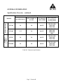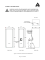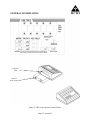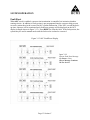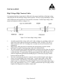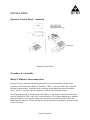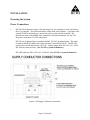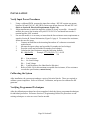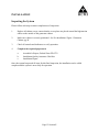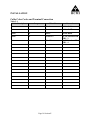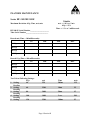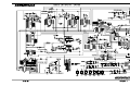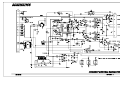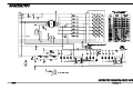
1
X-RAY GENERATOR
HF 300 / HF 600
HF 3SE / HF 3SEE
OPERATOR’S MANUAL
2146 East Pythian
Springfield, MO 65802
Phone (417) 864-6511
Fax (417) 864-7394
Part # AC-4000 Rev. 2
Revision Date: June 4th, 2004
TABLE OF CONTENTS
List of Revisions
Pre-Installation
Responsibility of Purchaser
Product Pre-Installation Data
Dimensions
Dimensions/Generator Cabinet
Dimensions/OCP Wall Mount
Dimensions/OCP Pedestal Mount
Mounting and Service Area
Environmental Requirements (Operating)
Radiation Warning
Installation Notice
HCMI Disclaimer
SECTION A Preface
Introduction
Manual Overview
System Description
Standard Configurations/Optional Features
Standard Configurations
Optional Features
Safety Notice
Safety Recommendations
Mechanical/Electrical
Compliance Notice
X-Ray Protection Notice
Shipping Information
Guarantee
Duration of Guarantee
Guarantee/Warranty Terms and Conditions
Buyers Remedies
SECTION B General Information ………………………
HF Series Generator Specifications
Dimensions HF 300, 600, 3SE, 3See, OCP (All Models)
Specifications Overview Table B-1
Power Requirements
General Electrical Compliance Requirements
Power Specifications (Single Phase Input Units) Table 2-1
Power Specifications HF-3SE/HF3SEE Table 2-2
1
Insert
Page A
Page A
Page A
Page A
Page B
Page C
Page D
Page E
Page E
Page 1
Page 2
Page 3
Page 1
Page 2
Page 2
Page 3
Page 3
Page 3
Page 4
Page 4
Page 5
Page 5
Page 5
Page 6
Page 6
Page 7
Page 7
Page 7
Page 7
Page 1
Page 2
Page 2
Page 2,3
Page 4
Page 4
Page 4
Page 5
Section A
Section B
TABLE OF CONTENTS
SECTION B General Information Continued
Electrical Requirements
Tube and Collimator Compatibility
Operator Control Panel
Display and Indicators
Mode Selection Keys
Bucky Selection Keys
Utility Keys
Power Controls
Figure 2-1 HF Series Generator/OCP Dimension
Figure 2-2 HF Series Operator Control Panel
General Cleaning
External Surface …………………………………………..
Internal Cabinet Cleaning
System Description
SECTION C System Operation
Overview
Power On/Off Procedures
To Power-On Your System
Power-On Self Test
To Power-Off Your System
Automatic Power-Off Feature
Full Charge Shutdown (Stored Energy Only)
Daily Procedures
Warm-Up Procedures
Table 3-1 Exposure Settings for Seasoning Procedures
Operating Modes
Setting Up to Take Exposures
Pre-Exposure Selections
Select An Operating Mode
Select Region of Interest
Figure 3-2 Auto Tech Menu
Select an Anatomical View
Figure 3-3 Anatomical View Selection Menu
Verify/Select Measurement
Figure 3-4 AEC Mode
Verify/Select AEC Density/Field
Density
AEC Field
2
Section B
Page 6, 7
Page 8
Page 8
Page 8
Page 8, 9
Page 9
Page 10
Page 10
Page 11
Page 12
Page 13
Page 13
Page 13
Page 13, 14
Page 1
Page 2
Page 2
Page 2
Page 3
Page 3
Page 3
Page 4
Page 4
Page 4
Page 4
Page 5
Page 5
Page 5, 6
Page 6
Page 7
Page 7
Page 7
Page 7
Page 8
Page 8
Page 8
Page 8
Page 8, 9
Section C
TABLE OF CONTENTS
SECTION C System Operation (continued)
Figure 3-5 Auto Tech Menu (AEC On, AEC Field Select)
Figure 3-6 AEC Mode Enabled, Field Selection Settings
Verify/Select Bucky
Verify/Select Exposure Factors
Typical Operators Display Prior To Exposure
Figure 3-9 Auto Tech Mode
Figure 3-10 Auto Tech, AEC Mode
Figure 3-11 Manual Mode
Figure 3-12 AEC Manual Mode
Fault Reset
Figure 3-13 AEC Fault/Reset Display
Figure 3-14 Exposure Fault Error Message
Image Quality
SECTION D System Diagnostics
Overview
Error Messages and Descriptions
Possible Faults
Main Circuit Breaker
SECTION E Installation – On HCMI Installation CD
Installation Instruction Advisory
Overview
Pre-Installation Guidelines
Electrical Requirements
Installation Procedures
Unpacking/Installing/Connecting the Equipment
Figure 5-1 Generator Dimensions
High Voltage Tanks
Figure 5-la Check Oil Level
Figure 5-2 High Voltage Tank Connections
High Voltage (High Tension) Cables
Figure 5-2a Connect High Voltage Cables
Figure 5-2b High Tension Cable Installation
Figure 5-2c Cabinet Top Cable Assembly
Operator Control Panel
Procedure for Assembly
Bucky/Collimator Interconnections
Powering the System
Power Connections
3
Section C
Page 9
Page 9
Page 9
Page 9, 10
Page 11
Page 11
Page 11
Page 12
Page 12
Page 13
Page 13
Page 13
Page 14
Page 1
Section D
Page 2
Page 2, 3
Page 4
Page 4
Page 1
Section E
Page 2
Page 2
Page 2, 3
Page 3
Page 3
Page 3, 4, 5
Page 5
Page 6, 7
Page 6
Page 7
Page 8, 9, 10
Page 8
Page 9
Page 10
Page 11, 12
Page 12
Page 12
Page 13
Page 13
TABLE OF CONTENTS
SECTION E Installation (continued)
Figure 5-2d Supply Conductor Connections
Verify Input Power Procedures
Calibrating the System
Verifying Programmed Techniques
Inspecting the System
Table 5-1 Cable Codes and Terminal Connection
Figure 5-3 Remote Switch Connections Diagram
Figure 5-4 Bucky Interconnection Diagram
Figure 5-9 Line Tap Panel HF 3SE
Figure 5-10 Line Tap Panel HF 3SEE
Figure 5-11 Din Rail Layout HF 300/HF 600
Figure 5-12 Din Rail Layout HF 3SE/HF 3SEE
SECTION F Calibration – On HCMI Installation CD
Introduction
Reference Voltage Calibration
Liquid Crystal Display
For SE Systems Only
HF-3SE/HF-3SEE
Regulated Power Supply Calibration (A-184)
+/-15 VDC Supply
Filament Voltage Supply
KVP Control Board (A-189)
Filament Control Regulator Board (A-263/A-190SE)
KV Calibration
Anode and Cathode H.V. Tank Balance Test
Figure 6-11 Utility/Maintenance Menu (Calibration Mode)
Figure 6-12 kVp Calibration
Figure 6-13 kVp Calibration Menu
Figure 6-13a kVp Calibration Select Menu
MA Calibration
Figure to Access kVp/mA Calibration Select Menu
Figure 6-14 mA Calibration Menu
Maximum Deviation kVp, Time, mA, mAs
Linearity Test
Reproducibility
AEC Calibration (Sets Normal to 1.2 Optical Density Nominal)
AEC Calibration, Expose Film and Measure Optical Density
AEC Linearity Test
AEC Reproducibility
4
Section E
Page 13
Page 14
Page 14
Page 14
Page 15
Page 16
Page 17
Page 18
Page 19
Page 20
Page 21
Page 22
Page 1
Section F
Page 2
Page 2
Page 2
Page 2
Page 3
Page 4
Page 4
Page 4
Page 5
Page 6
Page 6, 7, 8, 9
Page 6
Page 7
Page 8
Page 8
Page 9
Page 10, 11, 12
Page 11
Page 11
Page 12
Page 13
Page 13
Page 13, 14, 15
Page 15, 16
Page 16
Page 16
TABLE OF CONTENTS
Disabling Generator Exposure Audible Tone
SECTION G Programming/Utilities - On HCMI Install CD
Auto-Tech Technique Programming
Auto-Tech Programming Procedures
Figure 7-1 Auto-Tech Region of Interest Menu
Figure 7-2 Anatomical View Selection Menu
Figure 7-3 Main Program Edit Menu
Figure 7-4 SID and mA Selection Edit Menu
Figure 7-5 Bucky and CM Range Selection Edit Menu
Figure 7-6 Exposure Factor Selection Edit Menu
Utility/Maintenance Operations
Figure 7-7 Utility Maintenance Menu
Copy Master to EEPROM
Figure 7-9 Copy MASTER Verification Menu
Copy EEPROM to Master
Figure 7-10 Copy EEPROM Verification Menu
Print
Calibration
SECTION H Maintenance – On HCMI Installation CD
Introduction
Maintenance and Service Guidelines
Maintenance Procedures
Electrical Maintenance
Table 8-1 HCMI HF Series Calibration checklist
Series HF 300 Settings
Series HF 600 Settings
Series HF 3SE/HF 3SEE Settings
Linearity Test Average Exposure Ratio
AEC Linearity Test Average Exposure Ration
Table 8-2 Maintenance Checklist
SECTION I Schematics – On HCMI Installation CD
Power Module Driver PCB A-318
Interface PCB A-267
Regulated Power Supply PCB A-184
Microprocessor PCB A-272
Stored Energy Microprocessor PCB-A-172
KVP Contol PCB A-189
S.E. Filament Control Regulator PCB A-190
Filament Control Regulator PCB A-263
Filament Resistor PCB A-186
5
Page 17
Section G
Page 2
Page 2,3,4,5,6
Page 2
Page 3
Page 4
Page 4
Page 5
Page 6
Page 7
Page 7
Page 8
Page 8
Page 9
Page 9
Page 10
Page 10
Page 1
Section H
Page 2
Page 3
Page 2
Page 2, 3
Page 3
Page 4, 5
Page 6, 7
Page 8, 9
Page 10
Page 11
Page 12
Section I
10-6
10-7
10-8
10-9
10-10
10-11
10-12
10-13
10-14
TABLE OF CONTENTS
SECTION I Schematics (continued)
Distribution PCB A-185
Code Board PCB A-911
Power Shutoff PCB A-202
AEC Interface PCB A-194
Source Charger PCB A-288
Charge Monitor Circuit PCB A-299
Operator Control Panel PCB A-164
Operator Control Panel PCB A-198
HF-300/HF600 Rev. 1
HF 3SE (Stored Energy) Rev. 1
HF 3SEE (Stored Energy) Rev. 1
Eureka True Speed Wall Bucky
Section I
10-15
10-16
10-17
10-18
10-19
10-20
10-21
10-22
10-23
10-24
10-25
10-26
6
LIST OF REVISIONS
DATE
PAGE
DESCRIPTION
05/22/01
B
DESCRIPTION MICROPROCESSOR BOARDS A272-A172SE
16 SEC E
TABLE 5-1
21 SEC E
FIG 5-11 DINRAIL LAYOUT +30VDC
22 SEC E
FIG 5-12 DINRAIL LAYOUT +30VDC
2 SEC F
SOURCE CHARGER CAL. A 288 ES
3 SEC F
RE-WRITE CALIBRATION INSTRUCTIONS
5 SEC F
ADDED CORRECT DECIMAL VOLTAGE VALUES
6 SEC F
REMOVED kVp CALIBRATION TEXT
7 SEC F
PARAGRAPH C. D. REMOVED
8 SEC F
ADDED Kv WARNING FIGURE
9 SEC F
ADDED STEP 9
10 SEC F
REMOVED SES 410, DC REF, 380 DISPLAY WINDOWS
11 SEC F
FILAMENT RESISTOR BOARD A6 TO A 186
12 SEC F
AEC CALIBRATION RE-WRITTEN
14 SEC F
AEC CALIBRATION RE-WRITTEN
15 SEC F
AEC CALIBRATION RE-WRITTEN
16 SEC F
ADDED PART NUMBER MICRO. PROC. BOARD A-172/272
7 SEC G
OMIT NOTE
8 SEC G
ADD PART NUMBER A-172/272
9 SEC G
ADD PART NUMBER A-172/272
10 SEC G
OMIT COMPLETE PAGE
3 SEC H
SOURCE CHARGER VOLTAGE - SE ONLY
2 SEC D
ADDED ERROR MESSAGES
3 SEC D
ADDED ERROR MESSAGES
SCHEMATICS
A-299 CATHODE AND ANODE REVERSED
SCHEMATICS
A-267 C16 CONNECTION
SCHEMATICS
HF-300/HF-600 STAND BY POWER SUPPLY
SCHEMATICS
HF-3SE/HF3-SEE STAND BY POWER SUPPLY
3 SEC F
HF-3SE/HF3-SEE #5 CHANGED J1 TO J3
3 SEC F
HF-3SE/HF3-SEE #6 CHANGED J1 TO J3
12/21/01
14 SEC B
Amp MOM: 220 RMS CHANGED TO Amp MOM: 225RMS
02/07/02
SCHEMATICS
EUREKA TRUE SPEED BUCKY ADDED
03/12/02
SCHEMATICS
SEE 10-24. IN HF3-SEE UNITS, WIRE ADDED TO WIRE HARNESS
05/02/02
3 SEC F
06/18/02
SCHEMATICS
CHANGE THE SPECIFICATION FOR ADJUSTING THE OUTPUT VOLTAGE OF THE A-188/A-288
SOURCE CHARGER BOARD FRO +/-204-206 VDC TO +/-212 VDC.
REVISED SCHEMATICS
06/04/04
Entire Manual
09/10/01
Separated Operators Manual and Installation Manual. Installation Manual now provided through website
and on CD. Operators Manual provided on CD and Hard copy to customer.
Pre-Installation
The pre-installation document provides necessary information and data to plan and prepare the
customers site prior to equipment delivery and installation.
This document considers only the generators, operators control panel and associated
components.
RESPONSIBILITY OF PURCHASER:
Site preparation is the responsibility of the purchaser. The following should be considered before
delivery of system components.
• Install required material for radiation shielding.
• Complete room floor, ceiling and wall finish.
• Install wire raceway, conduit and ground points.
• Install proper size wire junction boxes with covers at locations specified in the installation plans.
• Install power mains with proper size conductors voltage rating and kVa (see Table 2-0 pg.14).
• Install safety devices according to service manual and local codes.
• Install wall support materials if specified for tubestand, wall holders and operators control panel.
• Contact local building inspectors before installation for any additional requirements necessary to
your location, etc.
Completing ALL pre-installation requirements will avoid delays and confusion.
PRODUCT PRE-INSTALLATION DATA
Dimensions:
Power Cabinet
LENGTH
WIDTH
HEIGHT
FOOTPRINT
WEIGHT
BTU
VOLUME
HF300
43.2cm
17 in
60.9cm
24 in
142 cm
56 in
26.35dm²
408 sq in
148 kg
325 lb
2559
378.62 dm³
23105 cu in
HF600
43.2cm
17 in
60.9cm
24 in
142 cm
56 in
26.35dm²
408 sq in
148 kg
325 lb
2559
378.62 dm³
23105 cu in
Stored Energy
LENGTH
WIDTH
HEIGHT
FOOTPRINT
WEIGHT
BTU
VOLUME
HF3 SE
43.2cm
17 in
60.9cm
24 in
142 cm
56 in
26.35dm²
408 sq in
183 kg
402 lb
2661
378.62 dm³
23105 cu in
HF3 SEE
43.2cm
17 in
60.9cm
24 in
142 cm
56 in
26.35dm²
408 sq in
183 kg
402 lb
2661
378.62 dm³
23105 cu in
A
Pre-Installation
continued
Figure 1 Generator Cabinet
B
Pre-Installation
continued
OPERATOR
CONTROL
PANEL
LENGTH
WIDTH
HEIGHT
FOOTPRINT
WEIGHT
BTU
VOLUME
ALL
MODELS
20.2 CM
8.0 in
24.5 CM
10 in
10.2 CM
4.0 in
5.18 dm²
80.3 sq in
1.3 kg
2.81 lbs
12.11
5.26 dm³
320 cu in
Figure 2 OCP Wall Mount
C
Pre-Installation
continued
Figure 3 Pedestal Mount
D
Pre-Installation
continued
Mounting and Service Area
The recommended mounting of each generator component is:
•
•
•
Power cabinet with high voltage transformers. Anchor to floor with four M10 (3/8) bolts
(not supplied by HCMI, Inc.). (See Figure 1).
Operators control panel with wall mount shelf (supplied by HCMI, Inc.) (See Figure 2).
Optional pedestal stand for operators control panel mounting (See Figure 3).
Note: For seismic areas, all components must be secured with anchors specified
by local standards.
THE MINIMUM RECOMMENDED FREE AREA FOR SERVICE
COMPONENT
POWER
CABINET
HF300/600
HF3 SE/HF3 SEE
OPERATORS
CONTROL PANEL
LEFT SIDE
RIGHT SIDE
FRONT
0.5 m
20 in
0.5 m
20 in
1.0 m
0.1 m
3.9 in
0.1 m
3.9 in
Completely
Free
REAR
0.1 m
3.9 in
Environmental Requirements (Operating)
Altitude - Temperature - Humidity. All ratings and duty cycles apply to ambient temperature
between 10° C (50° F) and 38° C (100° F), average relative humidity not exceeding 90 % and
altitude not exceeding 2400 m (8000ft) sea level. Environment must be controlled within these
limits.
Heat output of power cabinet with high voltage transformers under normal operating
environment can reach 750 watts (2559 BTU). Do not store materials on top of power cabinet.
Safety Devices and Exposure Interlocks. The door interlock switch indicates to the
operator when doorways to the x-ray room are open. It inhibits the x-ray exposure if room
door is open. X-ray warning light is a signal lamp installed outside of the x-ray room near
the entrance. The warning light cable should be routed to the power cabinet.
E
Radiation and Mechanical/Electrical Warning
(from NEMA Standards Publication/No. XR8-1979)
Radiation Warning for Diagnostic X-Ray Systems
X-rays are dangerous to both operator and others in the vicinity unless established safe exposure
procedures are strictly observed.
The useful and scattered beams can produce serious, genetic or potentially fatal bodily injuries to any
persons in the surrounding area if used by an unskilled operator. Adequate precautions must always be
taken to avoid exposure to the useful beam, as well as to leakage radiation from within the source housing
or to scattered radiation resulting from the passage of radiation through matter.
Those authorized to operate, test, participate in or supervise the operation of the equipment must be
thoroughly familiar and comply completely with the currently established safe exposure factors and
procedures described in publications such as Sub-Chapter J of Title 21 of the Code of Federal
Regulations, “Diagnostic X-Ray Systems and their Major Components”, and the National Council on
Radiation Protection (NCRP) No. 33, Medical S-Ray and Gamma-Ray Protection for Energies up to 10
MeV-Equipment Design and Use, as revised or replaced in the future.
Failure to observe these warnings may cause serious, genetic or potentially fatal bodily injuries to
the operator or those in the area.
Mechanical/ElectricalWarning for Diagnostic X-Ray Systems
All of the moveable assemblies and parts of X-ray equipment should be operated with care. Only
properly trained and qualified personnel should be permitted access to any internal parts. Live electrical
terminals are deadly; be sure line disconnect switches are opened and other appropriate precautions are
taken before opening access doors, removing enclosure panels or attaching accessories.
Do not remove the flexible high tension cables from the X-ray tube housing or high tension generator or
the access covers from the generator until the main and auxiliary power supplies have been disconnected.
When disconnecting high voltage cables, they must be grounded immediately in order to dissipate any
electrical charge that may remain on the cables or the tube.
Failure to comply with the foregoing may result in serious or potentially fatal bodily injuries to the
operator or those in the area.
1
THIS INSTALLATION AND
OPERATION MANUAL
MUST
BE DELIVERED TO THE
PURCHASER UPON
COMPLETION OF THE
INSTALLATION PRIOR TO
RELEASE OF THE
EQUIPMENT.
2
INSTALLATION OPERATORS MANUAL
S/N 1000 AND UP
5.0/above Software
REVISION 1
MANUAL # AC-4000 Rev-1
Notice
This manual is copyrighted and all rights are reserved. No portion of this
document may be copied, photocopied, reproduced, translated or reduced
to any electronic medium or machine readable form without prior consent
in writing from HCMI, Inc.
Disclaimer
HCMI, Inc. reserves the right to make changes to this manual and the
equipment described herein without notice. HCMI, Inc. shall not be liable
for any technical or editorial errors or omissions made herein or for
incidental, special or consequential damage of whatsoever nature resulting
from the furnishing of this manual or operation and performance of
equipment in connection with this manual. The original draft of this
document is written in English. The revision level of this document is
shown on the front cover.
© Copyright 2000 HCMI, Inc.
2146 East Pythian, Springfield, MO 65802 USA
HF® is a registered trademark of HCMI, Inc. All other product names or brand names
are trademarks of their respective holders.
3
PREFACE
SECTION A
PREFACE
Page 1 Section A
PREFACE
SECTION A:
INTRODUCTION
Congratulations on selecting the HCMI, Inc. HF Radiographic System. This is one of the
finest x-ray radiographic system designed for today’s market. HCMI, Inc. incorporates state of
the art technology along with TRUE 100 kHz high frequency resonant power source,
anatomically programmable technique selection and Quartz accurate electronics. Your new
instrument is designed to provide you with years of service with proper maintenance and care.
MANUAL OVERVIEW
The HF Series Operation Manual is intended for use by technologists and field engineers. Four
sections are enclosed. The first four provide the general information and system operation and
diagnostic procedures necessary to operate the HCMI, Inc. HF 300 system. All other
information regarding installation, troubleshooting and schematics can be obtained through our
website at www.newhcmi.com or on the CD Rom provided with your system.
♦
Section A PREFACE - includes a system description, safety notices and recommendations,
shipping information, compliance and x-ray protection notices and warranty information.
♦
Section B GENERAL INFORMATION - includes component specifications, system options,
an overview of operating modes and a description of system controls and indicators.
♦
Section C SYSTEM OPERATION - provides completed operating procedures, including power
on/off procedures, operation modes and exposure selection criteria.
♦
Section D SYSTEM DIAGNOSTICS - contains a description of error messages and a list of
common system faults with suggested responses.
♦
Section E INSTALLATION – provides installation and interconnection procedures.
♦
Section F CALIBRATION – provides calibration procedures, including kVp, mA, and system
electronics.
Page 2 Section A
PREFACE
SYSTEM DESCRIPTION
The HCMI, Inc. HF Generator is a anatomically programmable high-frequency x-ray generator.
Operating at 100 kHz resonance, the system offers remarkable performance as a diagnostic tool
with dramatic reductions in exposure times and patient radiation dose.
The HF series accommodates up to 72 views for 2500 anatomically programmed techniques.
After a thickness measurement is entered prior to exposure, the system automatically sets
programmed x-ray techniques and exposure factors, including AEC mode (if available), tube
selection, bucky selection, kVp, mA, and time. Programmed techniques can be modified at any
time through the control panel, either in the actual stored program or during the current exam.
During exposure, the AEC (optional) works in conjunction with Auto-Tech to provide uniform,
repeatable, high quality images with the smallest variation of optical density between patients.
The HF series is also available as a stored energy system that allows you to plug it into a
standard power receptacle (110 VAC).
Standard Configurations and Optional Features
Standard Configurations
The HF Series X-ray generators are state-of-the-art programmable systems. Since the
requirements of radiological practices vary widely, HCMI, Inc.’s basic system design provides
for easy future upgrades. The HF Series is available in four (4) base configurations, as follows:
Single Phase Models:
♦
♦
HF-300
HF-600
Stored Energy Models:
♦
♦
HF-3SE
HF-3SEE
110 VAC 50/60 Hz
220 VAC 50/60 Hz
Note: Stored Energy models can be connected to a standard 110 VAC or 220 VAC power
source.
Page 3 Section A
PREFACE
Optional Features
A variety of options provide the flexibility to meet individual requirements:
♦
Automatic Exposure Control (AEC) System: uses an ion chamber to assure proper
exposure times. The anatomical program selects the kV, bucky, mA and focal spot prior
to exposure; the AEC then terminates the exposure at the exact mAs required for a
perfect image. This provides uniform film density from patient-to-patient and film-tofilm.
♦
Pedestal Mount (PDL-1000): free-standing unit offers maximum in operator access and
convenience.
SAFETY NOTICE
♦
The HF Series High-Frequency X-Ray generator, manufactured by HCMI, Inc. will
function reliably when operated, maintained, and repaired according to the instructions
provided in this manual.
♦
HCMI, Inc. cannot assume responsibility for any malfunctioning of this equipment
resulting from improper operation, maintenance, repair, or from damage or modification
of its components.
♦
This equipment can be hazardous to both patient and operator unless established safe
exposure factors are observed.
♦
X-ray equipment is sold to be used exclusively by or under the prescribed direction of a
person who is licensed by law to operate equipment of this nature.
♦
HCMI, Inc. disclaims all responsibility from any injury resulting from improper
application of this equipment.
Page 4 Section A
PREFACE
Safety Recommendations
Mechanical/Electrical
All moveable assemblies and parts of this equipment must be operated with care. Manufacturer’s
equipment recommendations described in this manual (included with equipment) must be
observed.
Routine inspection of these assemblies should be performed by qualified service personnel on an
annual basis. Only properly trained service personnel should be permitted access to internal
assemblies, as live electrical components may be present. Be sure line disconnect switches are
open or other appropriate safety precautions are followed before service work is performed.
Failure to follow manufacturer’s or service personnel’s recommendations may result in
serious injury.
CAUTION: This equipment contains electrostatic sensitive devices.
Observe
proper grounding precautions before handling components or PCB’s.
!
WARNING: GROUNDING: this equipment is grounded to an earth ground
through the electrical power cord ground wire. It must be connected into a
properly grounded electrical box. Under no circumstances should it be operated
without the proper three wire power cord attached.
COMPLIANCE NOTICE
The certified model HCMI, Inc. x-ray system you have purchased has been designed, manufactured, and
calibrated to comply with governing Federal Regulations 21 CFR Subchapter J and the performance
standards attendant thereto.
Scheduled maintenance is essential to the assurance of continued integrity of this equipment with respect
to regulatory compliance. The continuance of certified performance to the regulatory standard is
incumbent upon the user’s diligent conformance to recommended maintenance instructions.
Upon installation, all certified products require the filing of Form FD-2579 “Report of Assembly of a
Diagnostic X-Ray System” by the Assembler (i.e., the installer) with the appropriate agencies; the
“Installation Quality Assurance Checklist” must be completed and properly distributed upon installation.
A copy of each form (pink copy) is provided to the user. The Installation Report is also completed by the
installer and returned to HCMI, Inc.
Note: Form FD-2579 is required for US installations; please observe the applicable
regulations of your particular local and/or national agencies.
Page 5 Section A
PREFACE
X-Ray Protection Notice
X-ray equipment may cause injury if used improperly. The instructions in this manual must be
adhered to when operating the HF series. HCMI, Inc.’s authorized dealers will assist you in placing
your system into operation.
Personal radiation monitoring and protective devices are available. You are urged to use them to
protect against unnecessary x-radiation exposure.
It is important that you be fully acquainted with applicable government radiation protection
regulations. Many provisions of these regulations are based on recommendations of the National
Council of Radiation Protection and Measurements. Recommendations for medical x-ray protections
are published in NCRP Report Number 102, available from:
NCRP Publications
7910 Woodmont Ave. Suite 1016
Bethesda, MD 20814
Those responsible for the planning of x-ray equipment installations must be thoroughly familiar and
comply completely with NCRP #49, “Structural Shielding Design and Evaluation for Medical Use of
X-Rays and Gamma-Rays of Energies up to 10 MEV”, as revised or replaced in the future.
Those authorized to operate, test, participate in or supervise the operation of the equipment must be
thoroughly familiar and comply completely with the currently established safe exposure techniques
and procedures described in publications such a Subchapter J of Title 21 of the code of Federal
Regulations, “Diagnostic X-Ray Systems and Their Major Components”, and the NCRP Report 102
referenced above, as revised or replaced in the future. Failure to observe these warnings may cause
serious injuries.
SHIPPING INFORMATION
♦
♦
♦
♦
The manufacturer is relieved of any responsibility for damage during shipment after the unit is
picked up by the carrier.
Examine all cartons and crates carefully at time of delivery. If damage is apparent, have delivery
driver write a “Damaged Shipment Note” on copies of the freight bill, sign it, and file the
appropriated carrier claim. Should you discover concealed damage, immediately notify the
transporting agent and ask for an “Inspection of Damage”. Carrier will not accept concealed
damage claim if filed after 15 days from date of receipt of merchandise.
Open crate or carton marked “packing list enclosed” first. Remove packing list and use as guide
to open remaining cartons. Do not dispose of packing material until packing list is matched with
actual parts received. Should there be a shortage or damage, notify the manufacturer
immediately.
Shipping storage limits: Ambient Temperature: 10C (50F) to 38C (100F): Relative Humidity: 0 to
85% non-condensing: Operating Altitude: 0 to 2400m (8000 Ft.)
Environment Must Be Controlled Within Limits
Page 6 Section A
PREFACE
Guarantee
Providing the warranty card (s) are completed and returned to the manufacturer within fifteen (15)
days after receipt of the equipment, HCMI, Inc. warrants to Buyer that any new product
manufactured by HCMI, Inc. (“Product”) will (1) be free from defects in material and
manufacturing and (2) conform substantially to applicable specifications in effect on the date of
shipment when subjected to normal, proper and intended usage by properly trained personnel. The
criteria for all testing shall be the applicable specifications, utilizing factory-specified calibration and
test procedures and instruments.
♦
ALL PRODUCT WARRANTIES AND ALL REMEDIES FOR WARRANTY FAILURES ARE
LIMITED IN TIME AS LISTED BELOW.
Duration of Guarantee
SEE GUARANTEE (WARRANTY) CERTIFICATE FOR DURATION
Any component furnished without charge to Buyer during the warranty period to correct a warranty failure shall be
warranted only to the extent of the unexpired term of the warranty of the original product. This warranty extends
only to the original purchase and is not transferable unless authorized in writing by HCMI, Inc.
GUARANTEE/WARRANTY TERMS AND CONDITIONS
Warranty consideration will be given only for products properly returned to the HCMI, Inc.
factory in accordance with HCMI, Inc.’s warranty/guarantee return procedure.
A fully completed Returned Goods Authorization/Service Report must be returned with the
defective item(s), if applicable. All shipping charges resulting from warranty returns are the
responsibility of the Purchaser or Dealer.
♦
An item “serial number” must be given to facilitate any warranty claim.
BUYERS REMEDIES
If HCMI, Inc. determines that any Product fails to meet any warranty during the applicable warranty
periods, HCMI, Inc. shall correct any such failure either at its option (a) by repairing, adjusting, or
replacing any defective or nonconforming Products, or defective or damaged part of parts of the
Product or (b) by making available at the place of assembly any necessary repaired or replacement
parts or assemblies. HCMI, Inc. shall have the option to furnish either new or exchange replacement
parts or assemblies. All replaced parts shall become the property of HCMI, Inc.
Installation, troubleshooting or repair service is not included in this warranty/guarantee.
Warranty of service is the responsibility of the dealer selling the equipment.
SEE WARRANTY CERTIFICATE FOR COMPLETE TERMS AND CONDITIONS OF
WARRANTY/GUARANTEE AS STATED BY MANUFACTURER.
Page 7 Section A
GENERAL INFORMATION
SECTION B
GENERAL INFORMATION
Page 1 Section B
GENERAL INFORMATION
HF Series Generator Specifications
This section contains system specifications and technical data for the HF generator, controls and
indicators for the Operator Control Panel.
DIMENSIONS
Power Cabinet
LENGTH
WIDTH
HEIGHT
FOOTPRINT
WEIGHT
BTU
VOLUME
HF300
43.2cm
17 in
60.9cm
24 in
142 cm
56 in
26.35dm²
408 sq in
148 kg
325 lb
2559
378.62 dm³
23105 cu in
HF600
43.2cm
17 in
60.9cm
24 in
142 cm
56 in
26.35dm²
408 sq in
148 kg
325 lb
2559
378.62 dm³
23105 cu in
Stored Energy
LENGTH
WIDTH
HEIGHT
FOOTPRINT
WEIGHT
BTU
VOLUME
HF3 SE
43.2cm
17 in
60.9cm
24 in
142 cm
56 in
26.35dm²
408 sq in
183 kg
402 lb
2661
378.62 dm³
23105 cu in
HF3 SEE
43.2cm
17 in
60.9cm
24 in
142 cm
56 in
26.35dm²
408 sq in
183 kg
402 lb
2661
378.62 dm³
23105 cu in
OPERATOR
CONTROL
PANEL
ALL
MODELS
LENGTH
WIDTH
HEIGHT
FOOTPRINT
WEIGHT
BTU
VOLUME
20.2 CM
8.0 in
24.5 CM
10 in
10.2 CM
4.0 in
5.18 dm²
80.3 sq in
1.3 kg
2.81 lbs
12.11
5.26 dm³
320 cu in
Specifications Overview
kVp Range:
kVp Accuracy:
mA Range:
mA Accuracy:
Time Range:
Time Accuracy:
mAs Accuracy:
40-125 kVp in 1 kVp steps
+ 5%
Model dependant (see table B-1)
+ 10% or 5 mA, whichever is greater
5 milliseconds to 6 seconds, over 200 steps
+ 1% + 3 milliseconds. Time is measured at the 90% level of the peak kV
+ 1% for time greater than or equal to 100 milliseconds and current greater
than or equal to 50 mA; otherwise, accuracy is a product of time and mA
accuracies
Duty Cycle:
1% of full load or x-ray tube limits, whichever is less
Heat Energy Output: AVG. 1936 BTU/hr
kW Output:
- HF 300 = 30 kW - HF 600 = 37.5 kW - HF 3SE = 30 kW
- HF 3SEE = 30 kW
♦
Note: Specifications for all configurations are identical, except as noted in chart and power
requirements. All specifications do not include measurement instrumentation accuracy.
Page 2 Section B
GENERAL INFORMATION
Specifications Overview continued
SPECIFICATIONS
STORED
ENERGY
SINGLE PHASE
MODEL
HF 300
HF 600
HF3SE
HF3SEE
MAXIMUM KW
30
37.5
30
30
KW @ 100KV @
0.1 SEC
30
30
30
30
KVP RANGE
1 KVP STEPS
MA STATIONS
S= small focus
L= large focus
40-125
25S 75S 150S
150L 200L
250L 300L
40-125
25S 75S 150S
200L 300L
400L 500L
600L
40-125
25S 75S 150S
150L 200L
250L 300L
40-125
25S 75S 150S
150L 200L
250L 300L
Table B-1 Generator Specifications
Page 3 Section B
GENERAL INFORMATION
Power Requirements
For any electrical installation, all electrical wiring/connections must be installed by a qualified
electrician and conform to national and local codes. Requirements for health care facilities
(National Electric Code NFPA No. 70) must be followed. Common power specifications are
described below and configuration dependant electrical requirements are listed in Figure 2-0,
page 6 Sec B.
General Electrical Compliance Requirements
These general guidelines must be followed in order to comply with the National Electric Code:
♦
All wiring must be copper.
♦
Insulation rating of the wire must be at least 50% of momentary current (as listed in
Figure 2-0, HF Electrical Requirements).
♦
All fuses, circuit breakers and disconnect switches should conform to the above
requirement of 50% of momentary current; the Disconnect Switch is to be located
within reach of the operator.
♦
For all installations, a separate earth ground (#6 AWG insulated wire) must be installed.
This #6 AWG insulated wire must be the ONLY wire connected to the ground terminal.
Power Specifications (Single Phase Input Units)
Specification
Input voltage: configured at
time of installation
Long Term Amps
HF-300
200-250 VAC
50/60 Hz
5 amps
HF-600
200-250 VAC
50/60 Hz
5 amps
Momentary Amps
225 amps RMS
250 amps RMS
Line Regulation
7% at full load
7 % at full load
Line Voltage Compensation
Fully automatic, max.
overall line voltage
variations (non-equip
related) not to exceed 7%
Fully automatic, max.
overall line voltage
variations (non-equipt
related) not to exceed 7%
Table 2-1. Power Specifications for Single Phase Input Units
Page 4 Section B
GENERAL INFORMATION
Power Specifications continued
Power Specifications (HF 300 600 Models) listed in Table 2-1 on page 4 Sec B and (HF 3SE
3SEE) listed in Table 2-2 below.
Specification
Input voltage: configured at
time of installation
Long Term Amps
Momentary Amps
HF-3SE
105-130 VAC
50/60 Hz
Less than 6 amps
Less than 20 amps
during rotor start up time
10% at 20 amp load
Line Regulation
Line Voltage Compensation
Fully automatic, max.
overall line voltage
variations (non-equip
related) not to exceed +/- 5%
HF-3SEE
200-250 VAC
50/60 Hz
Less than 3 amps
Less than 10 amps
during rotor start up time
10 % at 10 amp load
Fully automatic, max.
overall line voltage
variations (non-equipt
related) not to exceed +/- 5%
Table 2-2. Power Specifications for Stored Energy Units
Page 5 Section B
GENERAL INFORMATION
Electrical Requirements
Page 6 Section B
GENERAL INFORMATION
Electrical Requirements continued
For any electrical installation, all electrical wiring/connections must be installed by a qualified
electrician and conform to national and local codes. The guidelines listed below must be
followed in order to comply with the National Electric Code:
♦
All wiring must be copper
♦
Insulation rating of the wire must be a least 50% of momentary current (as listed in
Figure 2-0, page 6, Sec B, Electrical Requirements.
♦
All fuses, circuit breakers and disconnect switches should conform to the above
requirement of 50% of momentary current; the disconnect switch is to be located within
reach of the operator.
♦
For all installations, a separated earth ground (#6 AWG insulated wire) must be installed.
This #6 AWG insulated wire must be the only wire connected to the copper ground
terminal.
Requirements for health care facilities (National Electric Code NFPA No. 70) must be
followed.
Page 7 Section B
GENERAL INFORMATION
Tube and Collimator Compatibility
Tube: HCMI, Inc: BXT Series
Toshiba: E72 Series
Note: For tube types not listed, consult factory.
Collimator: HCMI, Inc./EUREKA LINEAR MC-150
HF generators are compatible with any automatic collimating system that provides an isolated
normally open switch which closes when the Automatic Collimation System presents an
“Exposure Ready” mode to the control; they are also compatible with any beam limiting device
that complies with 21 CFR Subchapter J intended for radiographic equipment other than general
purpose radiographic systems.
Operator Control Panel
The separate Operator Control Panel (shown in Figure 2-2) allows complete control and access
to all system functions and features. A twenty-one button touch-sensitive key pad combined
with a Liquid Crystal Display (LCD) and Light Emitting Diode (LED) technology provide userfriendly control and indication of system status. Controls and indicators described in the
following paragraphs can be referenced to Figure 2-2, HF Series Operator Control Panel.
Display and Indicators
LCD Panel: Displays techniques of corresponding selection keys providing a pre-indication of
kVp, mA, Time and mAs as well as measured thickness of the Region of Interest (ROI) in cm.
LED Indicators: A lit indicator lamp indicates an activated function.
Direction Keys: Pressing either the UP or DOWN arrow key (located above or below the LCD
display) will increase or decrease the corresponding factors, respectively.
Ready Indicator: This LED illuminates when the system has performed all of its self-checks
and is ready to take an exposure.
Mode Selection Keys
Manual Key: Allows for manual selection of all technique factors/parameters without automatic
system intervention.
AEC Key: Selects the optional Automatic Exposure Control (AEC) function. AEC uses an ion
chamber to assure proper exposure times.
Page 8 Section B
GENERAL INFORMATION
Mode Selection Keys continued
Auto-Tech Key: This key enables the Auto-Tech mode. After pressing Auto-Tech, the LCD
displays the eight (8) available anatomical regions for selection. After selection of an anatomical
region, up to nine available programs for the selected region are displayed. Once a program is
selected, the system automatically performs the following functions:
♦
selects tube, bucky, and SID required for selected view
♦
selects the kV and mA programmed for the anatomical thickness selected
♦
selects chamber, field(s), film speed, and back up time if AEC is enabled
These technique factors are used by the microprocessor to set the phototimer that terminates the
exposure at the proper mAs for uniform optical density.
♦
selects mAs if AEC is disabled
Bucky Selection Keys
Wall Bucky Key: This key selects the wall grid and AEC chamber, activating the wall bucky, if
present. This function can be programmed to activate when wall bucky techniques are used in
the Auto-Tech program.
Non-Bucky Key: This key allows for techniques that do not use a bucky. The LED illuminates
when “NONE” is selected. This function can be programmed to activate if a non-bucky
technique is used in an Auto-Tech program.
Table Bucky Key: This key selects the grid and AEC chamber, activating the bucky, if present.
This function is automatically activated if “TABLE” is used in an Auto-Tech program.
AEC Field Selection Keys: These keys select the field or combination of fields used to sense the
amount of radiation entering the film cassette. The operator selects the key with the appropriate
configuration of AEC field symbols. A shaded or hollow box indicates whether a field is used or
unused.
Page 9 Section B
GENERAL INFORMATION
Utility Keys
Prep Key: Boosts tube filament and rotor, checks all data lines.
Expose Key: Pressing this key initiates the exposure.
NOTE: This system incorporates many fail-safe devices (both mechanical and electrical) to
protect patients and technologist. If a microprocessor failure should occur during an exposure,
the operator control may be locked out with any or all indicators illuminated at random. In this
case, fail-safe devices are activated and all x-ray emission is terminated instantly.
Power Controls
Remote Power Switch: The system can be powered on or off by this switch without using the
main circuit breaker. In addition, system can be re-set with this switch after automatic power-off
feature shuts the system down. It is located on the OCP.
Page 10 Section B
GENERAL INFORMATION
!
WARNING: DO NOT ATTACH BRACKETS, MOUNT EQUIPMENT OR
DRILL HOLES IN THE POWER CABINET PANELS OR FRAME. DOING
SO WILL VOID THE WARRANTY AND COMPLIANCE TO UL 2601-1-2
TOP VIEW
HIGH TENSION
CABLE OPENING
24in
17in
(60.1cm)
(43.2cm)
24in
(60.1cm)
CABLE CLAMPS
FOR ALL INTERCONNECTING
CABLES FROM
GENERATOR
56in
56in
(142.2cm)
(142.2cm)
3in
(7.6cm)
COMPLIANCE
LABEL
22in
(56.5cm)
12in
(30.1cm)
220 VOLT POWER CABLE
FRONT VIEW
RIGHT SIDE
Figure 2-1 HF Series Generator and OCP Dimension
Page 11 Section B
REAR VIEW
GENERAL INFORMATION
Compliance
Label
Operator
Power Switch
Figure 2-2 HF Series Operator Control Panel
Page 12 Section B
GENERAL INFORMATION
Warning: Never attempt to clean or touch any part of the x-ray
generator’s internal components when power is turned on.
Switch off disconnect circuit breakers before cleaning.
!
General Cleaning
External Surfaces
Clean external covers and surfaces, particularly if corroding chemicals are present, with a cloth
moistened in warm water with mild soap. To rinse, wipe with a cloth moistened in clean water.
Never use cleaners or solvents of any kind. Also check painted surfaces and touch up as
required.
Internal Cabinet Cleaning
Remove power cabinet panels.
Caution:
Make sure that storage capacitors do not contain any residual
charge.
Visually inspect all areas for dust and foreign items. Carefully check for materials that could
cause shorts and remove them. If excess dust is present remove with air or vacuum cleaner.
Replace all safety covers and access panels before applying power.
System Description
HCMI, Inc. Generators described in this service manual comply with all the standards shown on
the label on page 13 of this section. Models listed in this manual are Class 1 equipment, type B
protection against shock. Generator models are ordinary medical equipment with enclosed
equipment cabinets without protection against ingress of liquids.
Mode of operation: All models are intermittent and classified as suitable for continuous
connection to the power supply mains. HCMI, Inc. Generator models are not suitable for use in
the presence of a flammable anesthetic mixture with air, oxygen or nitrous oxide.
Page 13 Section B
GENERAL INFORMATION
System Description
continued
X-RAY EQUIPMENT
CLASSIFIED WITH RESPECT TO ELECTRIC SHOCK, FIRE AND MECHANICAL
HAZARDS ONLY IN ACCORDANCE WITH UL 2601-1.
35YN
Page 14 Section B
SYSTEM OPERATION
SECTION C
SYSTEM OPERATION
SYSTEM OPERATION
Overview
This section provides the information necessary to operate the HF Series High-Frequency x-ray
generator.
The following operating procedures are outlined and described in detail:
♦
Power on/off procedures
♦
Seasoning procedures
♦
Operating modes and selection: Auto-Tech, AEC and Manual
♦
Printing techniques
Power On/Off Procedures
The following are step-by-step procedures to power-on/off your system according to its status.
There are three possible shut down states:
1. Complete Shut Down- The power switch and main circuit breaker were set to off. The
power line might have been disconnected
2. Remote Shut Down- The system was shut down with the remote ON/OFF power switch
on the Operator Control Panel (OCP).
3. Automatic Shut Down- Power to the system was automatically disconnected (via internal
timing circuit) after sixty minutes of inactivity.
To Power-on Your System:
From A Complete Shut Down
1. If necessary, connect the power line into the appropriate power receptacle.
2. Set the main circuit breaker on the system to the ON position.
3. Set the remote power switch (located on the OCP) to the ON position.
From A Remote Shut Down
1. Set the remote power switch to the ON position
From An Automatic Shut Down
1. Set the remote power switch to OFF.
2. Wait five seconds, then set the remote power switch to ON.
Page 2 Section C
SYSTEM OPERATION
Power-On Self Test
♦
When the HF Series generator system is first powered-on, “HCMI” appears on the
display while the system automatically runs a series of self checks to ensure proper
operation. If an error is detected, the actual error (i.e., “DOOR?”) will appear on the
LCD. Upon successful completion of the self checks, the display will return to the last
exposure setting that was used.
To Power-Off Your System
For Short Periods of Time
1.
2.
Set the remote power switch on the OCP to the OFF position.
Ensure indicators are dark. System is now shut down.
For Long Periods of Time
1.
2.
3.
Set remote power switch on the OCP to the OFF position.
Locate the main circuit breaker on the generator and set to the OFF position.
If desired, unplug the power line from the power receptacle or set the main power
disconnect switch to the OFF position. System is now shut down.
Automatic Power-Off Feature
To help save power and protect system electronics when left unattended, the HF Series generator
system is equipped with an automatic power-off feature that shuts down the unit.
After approximately sixty minutes of inactivity, the system will automatically power-off through
software control, leaving all switches in the ON position.
An audible tone will be emitted for approximately 30 seconds before the system shuts down and
“PRESS ANY KEY” will be displayed on the operator control panel.
To Abort the Automatic Power-Off Feature: Press any key on the operator control panel.
To Re-start after Automatic Shut Down: Refer to Power-On Procedures.
Page 3 Section C
SYSTEM OPERATION
Full Charge Shutdown (Stored Energy Only)
Occasionally, when the system has not been used for an extended period of time, or after
a period of heavy use, a full charge shut-down is recommended. A full charge will help
to restore the batteries to a sufficiently-charged condition.
1. Press arrow keys (See Figure 6-11, page 7 Sec F).
2. Leave the system in this state until the next day.
3. The next day, press MANUAL on the Utility Menu. System is ready for use.
Daily Procedures
Warm-Up Procedures
All tube manufacturers recommend seasoning procedures upon installation and daily warm-up.
Systems used infrequently should have tubes seasoned on a daily basis. It is important that these
procedures be performed to maintain both the tube manufactures and HCMI, Inc.’s extended
warranties.
A typical daily seasoning procedure is provided below. If the system has not been used for
several days, or upon installation, refer to the tube manufacturer’s instructions.
Procedure:
Table 3-1 Exposure Settings for Seasoning Procedures
EXPOSURE NUMBER
KVP
1
50
TIME (Seconds)
0.1
2
60
0.1
3
70
1.0
4
80
0.1
5
90
0.1
6
100
0.1
7
110
0.1
Page 4 Section C
SYSTEM OPERATION
Operating Modes
The HF Series can operate in four modes:
♦
Manual
♦
Automatic Exposure Control (AEC)
♦
Auto-Tech
♦
Auto-Tech with AEC
MANUAL MODE - requires manual calculation/selection of all x-ray techniques and exposure
factors.
AEC MODE - (optional) uses an ion chamber to ensure proper exposure times. Film density is
selectable via key pad control through selection of AEC fields in use and pre-programmed
film/screen combinations.
AUTO-TECH MODE - enhances radiographic imaging by automatically setting technique
factors. After a thickness measurement is entered, prior to exposure, the system automatically
sets programmed x-ray techniques and exposure factors including AEC mode (if available), tube
selection, bucky selection, kVp, mA, and time. Programmed Auto-Tech settings can be modified
at any time through the OCP, either in the actual stored program or for the current exam. During
exposure the AEC (optional) works in conjunction with Auto-Tech to provide uniform,
repeatable, high quality images with the smallest variation of optical density between patients.
AUTO-TECH WITH AEC MODE - after the technologist selects the anatomical view, the
system selects and sets all the optimum technique factors prior to exposure, including the wall or
table ION chamber.
Setting Up To Take Exposures
All aspects of x-ray techniques are entered at the OCP. Prior to taking an exposure, MODE,
BUCKY and TUBE must be selected. In addition, the displayed exposure factors (mA, Time,
kVp and mAs) should be verified. When operating in Auto-Tech mode, all x-ray techniques and
exposure factors are automatically entered for you.
Pre-Exposure Selections
This procedure outlines step-by-step instructions to set up x-ray techniques and exposure factors
prior to exposure. Since these procedures are mode and option dependant, refer to the
appropriate operating mode to begin. A flow chart on page 6 (Figure 3-1) provides a graphic
representation of the pre-exposure selection process. Selections are made by pressing the
appropriate key on the OCP or the UP/DOWN arrows on the LCD portion of the LCD.
Page 5 Section C
SYSTEM OPERATION
Pre-Exposure Selections
continued
Figure 3-1 Mode Selection Flow Chart
Select an Operating Mode
There are four possible modes of operation, depending on the options selected with your system.
The two basic modes are Auto-Tech and Manual. Automatic Exposure Control (AEC) can be
used as a stand alone mode (by itself) or in conjunction with Auto-Tech.
1.
2.
3.
Select a mode of operation by pressing the appropriate key: AUTO-TECH, AEC, or
MANUAL.
Once selected, ensure that the corresponding indicator is illuminated.
Continue with the required procedures as follows:
AUTO-TECH Selected
AEC Selected
MANUAL Selected
Go to Select Region of Interest
Go to Select Density
Go to verify/Select Tube and Bucky
Page 6 Section C
SYSTEM OPERATION
Select Region of Interest
When Auto-Tech is selected, x-ray techniques and exposure factors are automatically set
according to your specific program. The Auto-Tech Menu (example shown in figure 3-2, below)
will be displayed on the LCD.
1.
Select the appropriate region of interest by pressing UP or Down sector key associated
with the desired region.
Figure 3-2 Auto Tech Menu
Select an Anatomical View
After the region of interest is selected, a selection of available anatomical views will be
displayed.
1. Select the appropriate anatomical view by pressing the UP or DOWN sector key
associated with the desired view (see figure 3-3). Anatomical names and/or designations
can be modified, added or deleted from the program as described in Section G,
Programming.
Figure 3-3 Anatomical View Selection Menu
Page 7 Section C
SYSTEM OPERATION
Verify/Select Measurement
Selected SID is indicated by arrow as shown in Figure 3-4.
1.
2.
If necessary, use the UP/DOWN sector keys on the LCD to increase or decrease
the displayed cm. Initially, the CM value is set to 0.
If AEC mode is available continue with Enter/Verify CM.
Figure 3-4 AEC Mode
Verify/Select AEC Density/Field
When AEC is enabled, the AEC mode indicator is illuminated. A segment of the LCD displays
the currently selected AEC field and film density setting (example shown in Figure 3-6).
Available density settings (DNS value) are from +5 to -5. The 0 (zero) setting is depicted as N
(normal), which is the initial setting.
Density
1.
To increase or decrease density, press the UP or DOWN sector keys in the DNS field,
respectively. Each density step increases or decreases mAs by approximately 15%,
which, in turn, increases or decreases density, respectively.
AEC Field
A configuration of three boxes depicted on the LCD displays currently selected fields. A shaded
or hollow box indicates whether a field is used or unused, respectively.
NOTE: Ensure that the appropriate BUCKY mode is enabled prior to AEC FIELD selection.
1.
To select an AEC field, press one of the AEC Field keys until the desired configuration is
displayed on the LCD. There are seven possibilities.
Page 8 Section C
SYSTEM OPERATION
HCMI
AEC Field Continued
Figure 3-5 Auto Tech Menu
(AEC On, AEC Field Select)
Figure 3-6 AEC Mode
Enabled, Field Selection
Settings
Verify/Select Bucky
1.
In each operating mode, verify that the appropriate Bucky technique is selected (indicator
illuminated).
2.
If necessary, press the appropriate key: Wall Bucky, Table Bucky, or Non Bucky.
3.
Continue with Verify/Select Exposure Factors.
Verify/Select Exposure Factors
In auto-Tech mode, exposure factors (mA, kVp and mAs) are programmed. However, you can
modify any displayed factor or enter your own for manual or AEC modes. Once you have
verified that all x-ray techniques and exposure factors are correct, you can prepare to take an xray exposure.
Displayed exposure factor values (see example displays below) can be increased or decreased by
pressing the UP or DOWN arrow keys associated with the factor. When techniques are
modified from the original settings, UP/DOWN arrows are displayed next to the modified
technique to indicate that its corresponding factor was increased or decreased. For example, as
shown in Figure 3-8, mA was increased, kVp was decreased and mAs were decreased.
Note: Values displayed are not necessarily correct techniques; they are used only as an example.
Page 9 Section C
SYSTEM OPERATION
Verify/Select Exposure Factors continued
Figure 3-7 Initial Auto-Tech Menu, Manual CM Entry
Figure 3-8 Auto-Tech Menu with Modified Techniques
Preparing To Take an X-Ray Exposure
After exposure factors have been verified as above, ensure that all other x-ray exposure
precautions are met. If you have not already done so, position the patient accordingly and ensure
that the patient is comfortable. Refer to Image Quality (page 3-13) for additional suggestions.
Taking Exposures
For Instantaneous Exposures:
1.
Press and hold PREP until the PREP lamp is lit steady.
2.
Press and hold EXPOSE until the exposure is complete (system will emit an audible
tone). Note: If you remove your finger from exposure key before the exposure is
complete, the HYFOB Error will be displayed.
Page 10 Section C
SYSTEM OPERATION
Typical Operators Display Prior To Exposure
Auto Tech Mode
Figure 3-9
Auto Tech, AEC Mode
Figure 3-10
Page 11 Section C
SYSTEM OPERATION
Typical Operators Display Prior To Exposure continued
Manual Mode
Figure 3-11
AEC Manual Mode
Figure 3-12
Page 12 Section C
SYSTEM OPERATION
Fault Reset
When AEC mode is enabled, exposure time/termination is controlled via ionization chamber
sensing circuits. In addition, a back-up time is pre-programmed into the system to help prevent
excessive patient dose in the event of an AEC system malfunction. If the AEC exceeds the backup time, exposure will be terminated and a fault/reset message will be displayed on the OCP
display (example shown in figure 3-13). Press RESET to clear the fault. If the fault persists, the
system may be used in manual mode until the fault can be isolated or corrected.
Figure 3-13 AEC Fault/Reset Display
Figure 3-14
Exposure Fault Error Message.
Press Reset to Clear
If Error Message Continues
Call For Service
Page 13 Section C
SYSTEM OPERATION
Image Quality
You should always keep in mind the following basic parameters to achieve the best results in
diagnostic film quality:
•
Make sure that your system is operating properly by scheduling routine quality
assurance and maintenance as required.
•
Motion artifacts can be reduced by making the patient as comfortable as possible.
Always treat the patient with utmost care.
•
Patient positioning is achieved by making sure the area of interest is on the film.
•
Decreasing kVp value increases contrast.
•
Increasing mAs value darkens the image.
Page 14 Section C
SYSTEM DIAGNOSTICS
SECTION D
SYSTEM
DIAGNOSTICS
SYSTEM DIAGNOSTICS
Overview
This section is for system users or technicians to assist in locating and correcting minor system
faults, should they occur. The majority of these faults can be corrected without a service
technician. System faults that require the attention of a service representative are referenced in
Section H, Planned Maintenance.
Error Messages and Descriptions
When the unit will not expose, an audible alert will sound twice and one or more “error codes”
will appear on the display.
Refer to the following descriptions for assistance in interpreting the fault code displayed on the
Operator Control Panel:
BUCKY?
A bucky has been selected but it did not return the ready signal to start
exposure or AEC is selected and no bucky has been selected.
______________________________________________________________________________
DOOR?
The door interlock circuit is not closed.
______________________________________________________________________________
FAULT?
Indicates that there is a problem with the AEC.
______________________________________________________________________________
FIELD?
Control tried to take an exposure with AEC mode enabled but an AEC
field was not selected.
______________________________________________________________________________
FILAM?
Indicates there is a problem with the filament or filament control circuit.
______________________________________________________________________________
KVP?
Indicates a problem with the anode circuit or high voltage transformer.
______________________________________________________________________________
KVP-C?
Indicates a problem with the cathode circuit or high voltage transformer.
______________________________________________________________________________
FAULT
Indicates error during exposure.
RESET
Requires manual reset to resume operations.
______________________________________________________________________________
HYFOB
“Hold your finger on button”. Removed finger on expose switch too soon.
Short exposure.
______________________________________________________________________________
STACK
Microprocessor de-railed and locked out. Turn power off and reset after
ERROR
one (1) minute. This problem will return, contact factory.
Page 2 Section D
SYSTEM DIAGNOSTICS
Error Messages and Descriptions continued
NO MA?
Control tried to take an exposure, but there was no tube current during
exposure time.
____________________________________________________________________________
TUBE?
Oil pressure switch in x-ray tube open, check temperature
_____________________________________________________________________________
ROTOR?
Tube rotor is not getting correct current to start. Check rotor circuit.
_____________________________________________________________________________
BATERY?
If the Ready light is off, the batteries are not charged and a BATERY?
error is displayed when the PREP key is pressed; leave unit on to restore
voltage. (LOW BATTERY VOLTAGE)
_____________________________________________________________________________
OVERLOAD
Indicates that you have exceeded the maximum tube load rating. Reduce
technique factors.
______________________________________________________________________________
NO BUSS
Indicates fault in power buss voltage. Measure voltage at IGBT Driver
HF 300/600
boards 370-385 VDC, check fuses.
ONLY
______________________________________________________________________________
WARNING
Calibration data incorrect. Re-set to default values.
BAD Kv
KV calibration required, DO NOT USE GENERATOR.
______________________________________________________________________________
BACKUP?
AEC mode only, exposure stopped by backup timer, requires manual
reset.
______________________________________________________________________________
CODE BOARD
A-911 PC board problem, check connections.
ERROR
Page 3 Section D
SYSTEM DIAGNOSTICS
Possible Faults
Main Circuit Breaker
System circuit breaker on and OCP is dark
♦
Is the power line plugged into the receptacle or connected to the main circuit breaker?
♦
Is there power at the receptacle or the main circuit breaker?
♦
Is the remote ON/OFF switch on the OCP in the ON position?
♦
Auto Shut Off feature activated. If system was left unattended for sixty (60) minutes or
more, the Automatic Shut Off feature was activated. You can reset the system by setting
either main or remote ON/OFF switch to OFF, then back to ON position. Refer to
Section C, System Operation, for additional information.
♦
If any of the system checks outlined above do not solve the problem, refer to Section 8,
Planned Maintenance and Troubleshooting.
No Exposure
♦
Are any error messages displayed?
♦
In areas where power is known to be erratic, or if a “brownout” or power reduction has
taken place, it is necessary to check your input power.
Image Quality
♦
Motion artifacts? Relax the patient. Make the patient as comfortable as possible. Check
once again for proper positioning.
♦
Is there not enough contrast? Decrease kVp. Check the dark room, film expiration date,
chemicals and developer temperature.
♦
Correct film type (blue or green) sensitive, must match cassette screen type.
Page 4 Section D
INSTALLATION
SECTION E
INSTALLATION
INSTALLATION
Installation Instruction Advisory
In order to facilitate a timely installation and ensure compliance, it is recommended that the
installer review this manual in its entirety and then starting from the beginning, follow ALL
procedures in each section.
!
WARNING: Failure to follow the procedures in this manual may result in
electrical or mechanical safety hazards and failure to meet governmental
requirements.
CAUTION Hazardous voltage contact will cause electric shock or burn.
Disconnect all electrical power, including remote disconnects, before
servicing.
Overview
This section provides procedures for installing the HF Series generator, from pre-installation
guidelines to the final system inspection prior to operation. These procedures should be
reviewed carefully before beginning the actual installation.
WARNING: Installation procedures should be performed by trained, qualified personnel
only!
Pre-Installation Guidelines (Also see HCMI, Inc. Pre-Installation A-E for more
detail).
While site planning is the customer’s responsibility, the following are recommended guidelines:
Verify Space/Location of Equipment
In radiology site preparation, it is essential to verify that the location and space allocated for the
equipment is sufficient. Please refer to Figure 5-1 for the HF Generator dimensions; this
diagram specifically references the access panels and cable openings to assist you in this effort.
The room plan should show the following for the equipment:
Page 2 Section E
INSTALLATION
Pre-Installation Guidelines continued
♦
♦
♦
♦
All working and parked positions
Overall dimensions
Total equipment weights and power outputs
Structural mounting and attachment methods
Electrical Requirements
In addition to providing for the physical requirements of the equipment, it is also vital to prepare
for the power requirements. Please refer to Section B, General Information, Figure 2-0, for
power requirements and model dependent power specifications. This information is used to
prepare the system wiring and cabling.
Installation Procedures
The installation may be divided into the following tasks:
♦
Installing/connecting the equipment (See Figure 5-2d).
♦
Powering the system
♦
Calibrating the system
♦
Verifying programmed techniques
♦
Inspecting the system
Unpacking/Installing/Connecting the Equipment
Generator Cabinet
The HF Series generators are shipped in two crates. The large crate contains the x-ray generator
cabinet; the small crate contains two high voltage tanks and the Operator Control Panel (OCP).
Open the crate or carton marked “Packing List Enclosed” first. Remove the packing list and use
as a guide to opening the remaining cartons. Do not dispose of the packing material until the
packing list is matched with the actual parts received. Should there be a shortage or damage,
notify the manufacturer immediately.
Page 3 Section E
INSTALLATION
Unpacking/Installing/Connecting the Equipment continued
Note: The manufacturer is relieved of any responsibility for damage during shipment after
the unit is picked up by the carrier. Examine all cartons and crates carefully at the time of
delivery. If damage is apparent, have the delivery driver write a “DAMAGED
SHIPMENT NOTE” on copies of the freight bill, sign it, and file the appropriated carrier
claim. Should you discover concealed damage, immediately notify the transporting agent
and ask for an “INSPECTION of DAMAGE”. The carrier will not accept a concealed
damage claim if filed after 15 days from date of receipt of merchandise.
1.
2.
Stand the unit up and place it as close to the final location as possible.
Remove the covers from the cabinet as necessary, to gain access to the top equipment
shelf.
Note: When installing SE units only, the connectors at A288-A-J1 and A288-C-J1
must be connected to their respective locations on the Source Charger Boards.
Locate the OCP and place on the side.
If there are any loose wires resting on the top shelf, drape them across the side of cabinet.
3.
4.
!
WARNING: When unpacking and installing the high voltage tanks, DO NOT
turn them on their side. KEEP TANKS UPRIGHT AT ALL TIMES!
Page 4 Section E
INSTALLATION
Unpacking/Installing/Connecting the Equipment
!
continued
WARNING: DO NOT ATTACH BRACKETS, MOUNT EQUIPMENT OR
DRILL HOLES IN THE POWER CABINET PANELS OR FRAME,
DOING SO WILL VOID THE WARRANTY AND COMPLIANCE TO UL
2601-1-2
TOP VIEW
HIGH TENSION
CABLE OPENING
24in
17in
(60.1cm)
(43.2cm)
24in
(60.1cm)
CABLE CLAMPS
FOR ALL INTERCONNECTING
CABLES FROM
GENERATOR
56in
56in
(142.2cm)
(142.2cm)
3in
(7.6cm)
COMPLIANCE
LABEL
22in
(56.5cm)
12in
(30.1cm)
220 VOLT POWER CABLE
FRONT VIEW
RIGHT SIDE
Figure 5-1 Generator Dimensions
Page 5 Section E
REAR VIEW
INSTALLATION
High Voltage Tanks (Check oil level before installing, see Figure 5-1a below).
Figure 5-1a Check Oil Level
Place H.V. tanks on the top equipment shelf, inside the clamps. When facing the front of the
unit, anode tank should be on right side, cathode tank on left side.
1.
Locate ground wires for each tank (yellow/green, yellow/green and purple for anode;
yellow/green and yellow/green for cathode) and securely fasten to ground lug (GND) on
tank with 8/32 kep nut (see figure 5-2, page 7 Sec E).
Page 6 Section E
INSTALLATION
High Voltage Tanks continued
Figure 5-2 High Voltage Tank Connections
Page 7 Section E
INSTALLATION
High Voltage (High Tension) Cables
It is important that these instructions be followed for the proper installation of the high voltage
cable plug into the tube and high voltage tank receptacles. Please use proper handling to ensure
cable terminations and receptacles are clean and free of moisture. Connect high voltage cables
(anode and cathode) as follows in figure 5-2a.
Figure 5-2a Connect High Voltage Cables
1.
2.
3.
4.
Assemble onto the high voltage cable end of cable retaining nut, grounding washer and
strain relief if these parts are not already assembled to cable, (see figure 5-2a above).
Make certain the 10-32 X 1/4" locking screw is turned out so as not to interfere with
engagement.
High voltage cable plugs must be installed in the tube housing receptacle and the
transformer receptacle respecting proper anode and cathode polarity.
The cable terminal plugs and tube and transformer receptacles must be clean, dry and free
of any previously-used insulating compound. Be sure compression gaskets are in place
on the cable plug. To insure proper locking and grounding of the cable sheath do not
omit the compression gasket on the terminal plug as it is necessary for proper contact
between cable nut and flare.
Insert the termination plug into the receptacle socket (watch the nipple on the plug to
ensure correct positioning of the contact pins). Coat the entire surface of the cable
terminal insulator with insulating compound (supplied with cables) using clean, dry
plastic spoon or wooden stick,. Do not use fingers. Fully cover the entire surface with a
heavy coat (approximately 1/16 to 1/8 “). Build a pyramid at the tip of the plug with the
height of the compound even with the contact ends.
Page 8 Section E
INSTALLATION
High Voltage (High Tension) Cables continued
5.
With terminal key in alignment with receptacle key-way, insert the cable terminal plug
into its socket until all excess compound has oozed out. Make sure the contact pins are
engaged in the holes in the socket insulator and wipe off any excess compound.
6.
Tighten the cable nut while holding the cable firmly in place. Re-tighten after calibration
as some loosening may take place after the housing has been heated and cooled. With
cable nut properly tightened, secure with 10-32 X 1/4" locking screw.
Figure 5-2 b High Tension Cable Installation
7.
Place cover plates around the high voltage cables on the outside of the cabinet in order to
close off large openings as shown in Figure 5-2c, page10, Sec E.
Page 9 Section E
INSTALLATION
High Voltage (High Tension) Cables continued
Figure 5-2c Cabinet Top Cable Assembly
Page 10 Section E
INSTALLATION
Operator Control Panel
Step 1
Remove the Operator Control Panel from its shipping box and mount in the
location of your choice. The OCP includes a 20 foot interconnect cable,
consisting of two ribbon cables and one power cable. If additional length is
required, you may order this cable per foot, CP-C, for this cable configuration.
Step 2
If the OCP is used with the optional pedestal (PDL) (shown Pre-Installation, pg
D) or optional wall mount (HF-WM shown on page 12 Sec E), assemble and
mount the OCP.
Step 3
Connect OCP interconnect cables to power cabinet through cable entrance hole
separate from all power cables (rotor, collimator, locks, etc.). Do not wire tie low
voltage ribbon cables to high voltage or rotor cables.
Attach one cable to A-272-J3 (microprocessor board) marked 272-J3 connect
ground shield to ground. (Chassis).
Attach one cable to A-198-J2 (LCD driver board) marked 198-J2 connect ground
shield to ground. (Chassis).
Step 4
Connect gray power cable (remote ON/OFF control) to TB1, connections 1 and 2
on the POWER SHUT OFF board (A-202).
Page 11 Section E
INSTALLATION
Operator Control Panel continued
Operator Control Panel
Procedure for Assembly
Bucky/Collimator Interconnections
In general, bucky, table and tube housing assemblies are interconnected to the HF Series
generator via the Interconnect Panel (A-Din Rail). Table 5-1 provides cable color codes and
terminal connection data. Install the bucky according to the instructions provided with the
bucky. Figure 5-4 is interconnection diagrams for bucky and collimator wiring.
If a reciprocating bucky is installed in the table (Bucky 1), the jumper connection on interface
board A Din Rail at COM 1 and CONT, must be removed. If a reciprocating bucky is installed
in the wall (Bucky 2), the jumper connection on interface board A Din Rail at COM 2 and
CONT must be removed. Please note that all system interconnections must be secured with the
strain relief clamp.
Page 12 Section E
INSTALLATION
Powering the System
Power Connections
1.
HF-300/600 Generators require a line disconnect box (or according to local code) before
the x-ray generator. This switch should be within reach of the operator. A separate earth
ground, #6 AWG insulated wire, (green with yellow stripe) must be installed. The
ground wire must be the ONLY wire connected to the ground terminal. See Fig 5-2d
for power connections L1 & L2 and ground.
HF-3SE can be plugged into a standard switched 120 VAC grounded outlet. The outlet
receptacle should be within reach of the Operators Control Panel (OCP). The HF-3SE
unit is factory wired and tested at 120 VAC. Voltage ranges from 105-130 VAC, 50/60
HZ. Must be connected only. (See NOTE A, System Schematics).
HF-3SEE units are 200 to 250 VAC, 50/60 HZ. (See NOTE A, System Schematics).
Figure 5-2d Supply Conductor Connections
Page 13 Section E
INSTALLATION
Verify Input Power Procedures
1.
2.
3.
Using a calibrated DVM, measure the input line voltage. HF-3SE version can operate
between 105 and 130 VAC; HF-3SEE version scan operate between 200 and 250 VAC.
(Refer to Section B, Electrical Requirements, Figure 2-0).
Adjust transformer to match the input line voltage as closely as possible. On non-SE
models, the correct line location will yield 235 to 245 VAC measured between the 0
terminal and the 240V terminal.
For non-SE models, it is necessary to insure that the line resistance meets requirements as
stated in Section B, General Information, Figure 2-0 page 6. To measure line resistance,
follow the next five steps.
1.
Connect an Ohm/Stat to the incoming line and an AC voltmeter to terminals
marked meter.
2.
Measure the input voltage and record the Eo number (no load voltage).
3.
Press the switch and record the Eb number (load voltage).
4.
Calculate the Line Resistance using the following formula:
RL =Rd (Eo-Eb)
Example 2.75 (220-218) = 5.5 = 0.025
Eb
218
218
5.
RL = Line resistance
Eo = No Load Voltage
Eb = Load Voltage
Rd = Load Resistance (See Ohm/Stat for Rd value)
Refer to Table 2-0 for the maximum acceptable line resistance; if line resistance
exceeds the specification, contact factory.
Calibrating the System
After installation, the system must undergo a series of electrical checks. These are required to
validate system compliance. Refer to Section F, Calibration, and proceed to calibrate the HF
generator.
Verifying Programmed Techniques
After the calibration procedures have been completed, check the factory programmed techniques
for individual preference. Reference Section G, Programming/Utilities for procedures to edit
existing techniques or write new ones if and as needed.
Page 14 Section E
INSTALLATION
Inspecting the System
Please follow each step to ensure completeness of inspection.
1.
Replace all cabinet covers; ensure that the cover plates are placed around the high tension
cables on the outside of the generator cabinet.
2.
Make sure cabinet is securely positioned. See Pre-Installation /Figure 1 Generator
Cabinet, pg. B.
3.
Check all controls and indicators to verify operation.
4.
Complete the required paperwork:
a.
b.
c.
Assembler’s Report, Federal Form FD-2579
Installation Quality Assurance Checklist
Installation Report
Once the system has passed all steps for this final inspection, the installation can be called
complete and the system is now ready for operation.
Page 15 Section E
INSTALLATION
Cable Color Codes and Terminal Connection
Table 5-1
Cable Description
Rotor
Gauge
16
Wire Color
Black
Connection
A Din Rail/6
Rotor
16
Green
A Din Rail/7
Rotor
16
White
A Din Rail/8
Rotor
16
Yellow T5
Rotor
16
Blue T6
A- 267 Interface BD
TB1 - 3
A-267 interface BD
TB1 - 4
Page 16 Section E
INSTALLATION
Figure 5-3 Remote Switch Connection Diagram, (OCP PC Board)
Page 17 Section E
INSTALLATION
Figure 5-4 Bucky Interconnection Diagram
Page 18 Section E
INSTALLATION
Line Tap Panel Used in the HF3 SE
HF3-SE COMPENSATION DIAGRAM
Figure 5-9 Line Tap Panel HF3 SE
Page 19 Section E
INSTALLATION
Line Tap Panel Used in the HF3 SEE
Figure 5-10 Line Tap Panel HF3 SEE
Page 20 Section E
INSTALLATION
Din Rail Layout - Non SE Models
Figure 5-11 Din Rail Layout
Page 21 Section E
INSTALLATION
Din Rail Layout - SE Models
Figure 5-12 Din Rail Layout
Page 22 Section E
CALIBRATION
SECTION F
CALIBRATION
CALIBRATION
Introduction
The HF generator you have purchased has been factory configured and calibrated. It is
necessary, for you to perform the following electrical checks to validate the system compliance,
unless otherwise instructed. For additional information, the NEMA Standards Publication /No.
XR8-1979, “Test Methods for Diagnostic X-ray Machines for Use During Initial Installation” is
recommended.
NOTE: Please refer to Figure 8-7 for circuit board locations.
Reference Voltage Calibration
1.
Connect a DMV across TP1 of the microprocessor and ground. While monitoring the
DVM, adjust R17 to -10.20 + 0.01 V.
Liquid Crystal Display
1.
To adjust the intensity of the liquid crystal display (LCD), rotate R33 either clockwise or
counterclockwise on the microprocessor board.
Source Charger Calibration (A-288SES)
For SE Systems Only
Note: A fully charged system is required to set R5, R21 and R34 to proper settings.
CALIBRATION
HF-3SE/HF-3SEE
1.
2.
3.
4.
5.
6.
7.
8.
9.
Connect the DVM to GND and A-288C-TP3. Adjust R5 to read between +210 and +212
VDC. D6 should be flashing.
Connect the DVM to GND and A-288C-TP4. Adjust R21 to read between -210 and -212
VDC. D9 should now be flashing.
Connect the DVM to GND and A-288A-TP3. Adjust R5 to read between +210 and +212
VDC. D6 should be flashing.
Connect the DVM to GND and A-288A- TP4. Adust R21 to read between -210 and -212
VDC. D9 should be flashing.
Turn the main circuit breaker off. Wait until D6 and D9 LED’s go off and disconnect A288C J3. Turn the main circuit breaker back on.
Connect the DVM to GND and A-288A- TP2. Adjust A-288A-R34 to read +4.8 volts.
Turn the main circuit breaker off. Wait until A-288A&C D6 and D9 LED’s go off,
replace A-288C J3. Turn the main circuit breaker back on. Measure TP2 on A-288C
board for 7.3 VDC, adjust R34 for correct setting.
Connect positive and negative leads of the DVM to A-288C TP3 and TP4. Verify that
the measured voltage is 422 + 2 VDC. Repeat DVM connections on A-288A and
measure same voltage.
Connect positive and negative leads of the DVM to A-188 TP-3 and TP-4. Verify that
the measured voltage is 422 ± 2 VDC
If the actual voltage measured on the DVM is equal to or within ± 2 volts of the SES
voltage displayed on the OCP, press manual key to return to normal operating mode. If
not, adjust A-188-R34 until the voltage on the OCP is within ± 2 volts of the measured
voltage on the DVM.
Note: Steps 1 through 4
If D6 or D9 LED’s are on constant, further charging is required. Monitor
respective test point and adjust as necessary.
If either D6 or D9 will not illuminate regardless of voltage, verify +15 VDC and -15
VDC.
Page 3 Section F
CALIBRATION
Regulated Power Supply Calibration (A-184)
+/- 15 VDC Supply
1.
Connect a voltmeter between +15V TP and GND. Observed voltage should be + 15 +
0.2 VDC.
2.
If observed voltage is within specification, continue with step 3. If not, adjust the voltage
as follows:
a.
Observed voltage Low - Adjust R7 clockwise until voltage is within specification.
b.
Observed voltage High - Adjust R7 counter-clockwise until voltage is within
specification.
Connect a voltmeter between the -15V TP and GND. Observed voltage should be
between -14.4 and -15.6 VDC. (No adjustment provided).
3.
Filament Voltage Supply
1.
2.
Connect the voltmeter between TP1 and GND. Observed voltage should be: 50 VDC +
.02. For SE units, voltage should be 33 to 36 volts factory set)..
If observed voltage is within specification, regulated power supply calibration procedures
are complete. If not, adjust the voltage as follows:
a.
Observed voltage Low - Adjust R23 on the (A-184) board clockwise until the
proper voltage is reached.
b.
Observed voltage High - Wait a minute to discharge C8, then adjust R23 counterclockwise. Continue until voltage is lower than desired and turn R23 clockwise to
the proper voltage.
Page 4 Section F
CALIBRATION
KVP Control Board A-189
!
Warning: Do not adjust voltages on these boards during routine
installation electrical checks. Calibration is required only upon board or
High Voltage Tank replacement.
!
Warning: Set and stabilize -10.20 on microprocessor BD TP1.
ANODE
1.
2.
3.
4.
5.
Locate the A-189A board and connect a voltmeter between TP1 and GND.
Adjust R2 for -0.80 + .005 VDC.
Connect a jumper between TP3 and GND. Remove voltmeter from TP1 and reconnect to
TP2.
Adjust R5 for -0.75 VDC + .005 at TP2.
Remove jumper and voltmeter.
CATHODE
1.
2.
3.
4.
5.
Before removing old cathode BD A-189C, record voltage on TP2 with TP3 grounded (ie:
.650 -.790 VDC).
Remove power (turn-off). Install new cathode BD A-189C.
Connect voltmeter to TP1 and GND adjust R2 for -0.80+ .005 VDC.
See 3 above.
Set R5 to recorded voltage.
Page 5 Section F
CALIBRATION
Filament Control Regulator Board (A-263/A-190SE)
1.
No adjustments are to be made on this board. This has been done at the factory. If any
service to this board is required, notify HCMI, Inc.
!
WARNING: The following calibration procedures involve taking X-ray
exposures. All personnel should be behind the protective barriers. X-rays
can be dangerous unless proper precautions and procedures are adhered to.
CAUTION: Before calibrating unit, perform seasoning procedures
recommended by tube manufacturer or the seasoning procedures described in
Section C, System Operation.
KV Calibration
Anode and Cathode H.V. Tank Balance Test
To calibrate kVp, a dynalyzer kVp meter (or equivalent kVp bleeder tank) is required. Please
follow the next procedures:
1.
If you have not already connected a kVp bleeder tank to the system, it should be
connected in series between tube and H.V. tanks.
a. Switch kVp bleeder tank to anode and take an exposure at 100 kVp, 200L mA, 20
mAs (100L mA, 10 mAs for HF-3 SE units). The kVp meter will read near 50
kVp. From the OCP, adjust kVp and repeat exposure until the kVp meter reads
50 kVp.
b. Switch kVp bleeder tank to cathode and take an exposure without changing the
OCP settings. If the kVp meter does not read 50 + /-1 kVp, adjust R5 cathode kV
board and repeat exposure until the kVp meter reads 50 + /-1 kVp.
!
Warning: To avoid injury to personnel, ensure that system power is removed
prior to making and removing any electrical connections.
Page 6 Section F
CALIBRATION
KV Calibration continued
2.
Access kV CALIBRATION mode as follows:
Note: If power to the system has been off, set main power switch to ON.
a. To access the Utility/Maintenance Menu (Calibration Mode):
Figure 6-11 Utility/Maintenance Menu (Calibration Mode)
b. Press MANUAL key first to enter manual mode then press down arrows
simultaneously under exposure counter and seconds. (Figure 6-11)
CALIBRATION
HCMI
KV Calibration continued
c. Press CAL kVp.
Figure 6-12 The kVp Calibration Menu will be displayed
Figure 6-13 kV Calibration Menu
3.
Take an exposure and verify that the kVp meter display indicates a kVp value identical to
the value selected.
4.
If measured kVp is correct, continue with Step 6. If not, press KV MEAS up or down
buttons until the KV MEAS value corresponds with the actual kVp output displayed on
the kVp meter.
5.
Press NEXT. The LCD display will change to calibrate at the next kVp setting with the
same mA and time.
6.
Take another exposure and verify that the kVp meter display indicates a kVp value
identical to the value selected.
7.
If measured kVp is correct, continue with Step 9. If not, press KV MEAS up or down
buttons until the KV MEAS value corresponds with the actual kVp output displayed on
the kVp meter.
Page 8 Section F
CALIBRATION
KV Calibration continued
8.
Press NEXT. The microprocessor will calculate and display the slope and offset and
store these numbers in memory. The LCD will display the kVp/mA Calibration Select
Menu.
Figure 6-13a
9.
Verify kV Calibration settings. Take several exposures out of calibration mode (60-7090 kV etc).
Page 9 Section F
CALIBRATION
mA Calibration
!
Warning: The following calibration procedures involve taking X-ray
exposures. All personnel should be behind the protective barriers. X-rays
can be dangerous unless proper precautions and procedures are followed.
Caution: Excessive anode heat will effect mA Calibration accuracy.
1.
To measure mA, use either a dynalyzer or Philips PM 2618 mAs meter or equivalent.
a. If you are using a dynalyzer, it should be connected in series between the tube and
anode H.V. tank. The cathode tank should be directly connected to the X-ray
tube. The dynalyzer should be set for kVp trigger at 90%. In this set-up, kVp
will read ½ of actual, but mA will be most accurate.
b. If an mAs meter is used, disconnect the mA lead (purple/white) from the mA
terminal on the anode H.V. tank. Connect the mAs meter in series between the
mA terminal and the mA lead (purple/white) on the anode H.V. tank. This
measurement may not be as accurate as when using the dynalyzer for times of 50
msec and below.
c. When calibration is complete, disconnect the mAs meter and reconnect the mA
lead (purple/white) to the anode H.V. tank mA terminal.
2.
Access mA calibration mode as follows: (See figure 6-11)
a. Press CAL MA directly from the kVp/mA Calibration Select Menu.
b. Or, if power to the system has been off, set main power switch to ON. To access
the Utility/Maintenance Menu, see Figure A, page 3 Sec. F.
Page 10 Section F
CALIBRATION
mA Calibration continued
Press CALIB to access the kVp/mA Calibration Select Menu.99
♦
♦
Press CAL mA. The LCD displays the mA Calibration Menu
Press mA station arrow key to select mA.
mA Station CAL-Select Press arrow UP or Down
Figure 6-14 mA Calibration Menu
Note: kVp and mA have been PRE-SET; the displayed values are model dependent.
3.
Take an exposure and verify that the mA meter display indicates an mA value (see
Specification Overview, Section B or page 11, Section F.) to the value displayed under
CALIB (25S as shown above in Figure 6-14).
Page 11 Section F
CALIBRATION
mA Calibration continued
4.
If measured mA is within specification (as indicated in Section 2, General Information),
continue with Step 5. If not, adjust the mA code up or down (by pressing the
corresponding buttons on the LCD) to increase or decrease the mA code reading.
Note: If the specified mA cannot be obtained using the available mA code range (0-255
mA), the resistance on Filament Resistor Board A186 must be increased (when 0 is
reached) or decreased (when 255 is reached) as required. This may occur, for example,
when the high tension cable length or the tube is changed. After changing resistance,
repeat Step 4.
5.
Repeat Steps 3 and 4 until the mAs meter reading and displayed mA value are within
specification. When the measured and displayed values are within specification, press
NEXT to calibrate at the next kVp steps.
6.
Repeat the calibration procedure (steps 3 thru 5) for each mA station and using each kVp
step. Each mA station requires calibration at each of the six (6) pre-set kVp/time steps.
Note: When NEXT is pressed at the end of each mA station setting, the LCD momentarily
displays a “Saving mA Code” message. During this time, the microprocessor is entering
the calibration data. Caution: DO NOT OVERHEAT X-RAY TUBE: ALL
SIX BREAK POINTS MUST BE ENTERED TO CALIBRATE mA.
7.
After completion of all mA stations, set main power switch to OFF and reconnect the
system.
Maximum Deviation kVp, Time, mA, mAs
1.
Set the dynalyzer for mA (90% trigger level on kVp).
2.
Refer to the data sheet in Section 8, Planned Maintenance and Troubleshooting, and take
exposures at the required settings.
3.
Run a print-out and record on the data sheet.
4.
Make sure that the following are within tolerance:
a. mA- + 10% or 5mA, whichever is greater.
b. kVp - + 5%
c. Timing - + 1% + 3 milliseconds. Time is measured at the 90% level of the peak kV.
d. mAs - + 12% for time greater than or equal to 100 milliseconds and current greater
than or equal to 50 mA; otherwise, accuracy is a product of time and mA accuracies.
Page 12 Section F
CALIBRATION
Linearity Test
1.
Take ten (10) exposures with the exposure factors from the appropriate data sheet in
Section H, Planned Maintenance. Ensure that the dynalyzer or radiation monitor is set
for mR, run a printout and record as Test # 1.
2.
Take ten (10 exposures with the exposure factors from the appropriate data sheet in
Section H. Ensure that the dynalyzer or radiation monitor is set for mR, run a printout
and record as Test #2.
3.
Using the data from Tests #1 and #2, refer to the Linearity Data Sheet (Section H) and
calculate the Average Exposure Ratio. It must be equal to or less than 0.1.
Reproducibility
1.
Take ten (10) exposures using the settings indicated on the data sheet in Section H,
Planned Maintenance. Ensure that the dynalyzer or radiation monitor is set for mR, run a
printout and record as Test # 3.
2.
After the tenth exposure, select coef. On dynalyzer, mR reading must be less that or equal
to 0.05. If a Dynalyzer III is not used, calculate the C.O.V. (Coefficient of variation)
according to NEMA Standards Publication XR8, part 2, page 11, par. D.
3.
Record on data sheet.
AEC Calibration (Sets Normal to 1.2 Optical Density Nominal)
Note: HCMI, Inc. factory adjust all AEC systems using a similar Ion Chamber. Do not adjust
the ION Chamber Gain Pot until the following test settings are verified.
The following procedures are for the purposes of using a table bucky. Make appropriate
adjustments and modifications if using a wall bucky.
Before proceeding, turn the system OFF and then ON to initialize the settings. Do not press
PREP or EXPOSE. Select the AEC mode.
1.
Position ionization sensor under beam at 40 inches from the focal spot.
2.
Press “Auto-Tech Mode” and select lumbar lateral view, wall or table bucky and
AEC Mode, (select center field on Ion Chamber).
Page 1 Section F
CALIBRATION
HCMI
AEC Calibration continued
3.
Set mA to 75S and 60 kVp. (Note: Back-up mAs is factory set at 540 mAs).
4.
Attach + voltmeter lead to A-194 TP2 and verify voltage reads 0 VDC, adjust R33 (kV
offset) if necessary.
5.
Attach + voltmeter lead to A-194 TP3 and common test point, press and release “PREP”
button on OCP and verify 1.16 VDC at 60 kVp is present, adjust R32 (kV ref. gain) if
necessary.
6.
Cover AEC fields of Ion chamber with plastic container of 15 cm (6") water.
7.
Set mA to 75S and 60 kVp. Take exposure. mAs reading should be 38 - 40. To
increase mAs, turn R56 clockwise. To decrease mAs, turn R56 counterclockwise.
8.
If proper mAs cannot be obtained @ 75S/60kVp by adjusting R56, turn R12
counterclockwise.
Figure 6-15 Field Locations
9.
Set mA to 150L and kVp to 80. Take exposure. Mas reading should be 7.7 - 8.0. To
increase mAs, turn R55 clockwise. To decrease mAs, turn R55 counterclockwise.
Page 14 Section F
CALIBRATION
HCMI
AEC Calibration continued
10.
If proper mAs cannot be obtained @ 150L/80kVp by adjusting R55, turn R12 clockwise.
11.
When proper mAs levels are set at these two (2) stations, check 150L @ 100 kVp. Mas
should read approximately 3.6. Check 150L @ 120 kVp, mAs should read approximately
2.0.
12.
To increase optical density of film at kVp setting 73 or below, turn R56 clockwise. To
increase optical density of film at kVp setting of 74 and above, turn R55 clockwise.
AEC Calibration, Expose Film and Measure Optical Density
The following procedure requires film processing and measuring optical density
with a densitometer.
1.
Test film processor for optimum film development.
♦
Check developer temperature specifications.
♦
Check developer quality and specific gravity.
♦
Check film processor replenish rates.
2.
Test film for base fog (should be less than .19 OD).
3.
Test and verify film and cassette screens for correct match and speed (400 blue, 400
green, etc.).
4.
Test darkroom safe-light. Process film exposed only to safe-light and measure optical
density.
Place a plastic container with 8-10 ”(inches) of water in the x-ray beam, load a film cassette and
place in cassette tray. Measure optical density at 65 kVp and 105 kVp. * The two (2) films
should not vary in optical density by more that .1.
*The optical density of the first film is equal to the exposure mAs. Record the exposure mAs
after the exposure, displayed in the mAs screen window. Measure optical density and calculate
“target mAs” = (desired density divided by measured density) x elapsed mAs. Example: The
elapsed mAs is 20 mAs and the density is 1.0 OD. Desired is 1.20 “target mAs” = (1.20 ÷ 1.0) x
20 = 24. The new mAs to achieve 1.20 OD will be 24 mAs.
Page 15 Section F
CALIBRATION
HCMI
AEC Calibration, Expose Film and Measure Optical Density continued
Two (2) Ion chambers installations should not vary by more than .12 OD wall to table.
Chamber gain adjustment: If a second chamber is used, it might be necessary to adjust the gain
of the second chamber to match the one adjusted and calibrated to 1.2 optical density. Adjust the
pre-amp pot marked chamber gain, take an exposure and measure optical density. Match within
.12 optical density.
Auto-tech AEC can be programmed for each view, in addition to bucky selection wall or table,
see Programming Utilities, Section G.
AEC Linearity Test
1.
Take ten (10) exposures in the AEC mode using the exposure factors from the data sheet
for Test 1. Be sure that the dynalyzer or radiation monitor is set for mR. Run a printout
and record as Test 1.
2.
Take ten (10) exposures in the AEC mode using the settings for Test 2. Be sure that the
dynalyzer or radiation monitor is set for mR. Run a printout and record as Test 2.
3.
Using data from Tests 1 and 2, calculate the average exposure ratio. Results must be
equal to or less than 0.1.
AEC Reproducibility
♦
Take ten (10) exposures using the settings for Test 3 on the data sheet.
♦
After the tenth exposure, select coef. on the dynalyzer. The mR reading must be less than
or equal to 0.05. If a Dynalyzer III is not used, calculate the C.O.V. (Coefficient of
variation) according to NEMA Standards Publication No. XR8, part 2, page 11, par.D.
♦
Record on the data sheet.
Page 16 Section F
CALIBRATION
Disabling Generator Exposure Audible Tone
In certain installations it may be desirable to disable the EXPOSURE tone that is generated at
the generator electronics cabinet (located near the patient). Note that the following procedure
will only disable the audible tone at the generator electronics cabinet. An audible tone will still
be heard at the Operator Control Panel (OCP). Please proceed as follows to preform this task.
1.
To disable the “Exposure On” audible tone within the generator cabinet (power unit),
cut either lead of resistor R54, which is mounted on microprocessor board A-172.
Page 17 Section F
PROGRAMMING UTILITIES
SECTION G
PROGRAMMING/UTILITIES
PROGRAMMING UTILITIES
Auto-Tech Technique Programming
The following procedures provides step-by-step instructions for editing an existing technique or
writing a new one and adding it to the Auto-Tech memory. Auto-Tech has the capability of
recalling up to 72 anatomical views by storing up to 9 techniques in each of the 8 anatomical
regions. Any of the existing x-ray techniques can be edited to suit the individual needs of your
practice.
For the purpose of this description, the LCD display is divided into 10 sectors as shown in Figure
7-1, below. Each sector is controlled by the corresponding sector key located above or below
that sector.
Auto-Tech Programming Procedures
1.
2.
Press AUTO-TECH to select Auto-Tech mode.
Select the region of interest (ROI) where the technique is (to be) stored by pressing the
corresponding sector key. For example, to edit the LUMBAR region in the main menu
(see Figure 7-1), press sector key 5.
Figure 7-1 Auto-Tech Region of Interest Menu
Page 2 Section G
PROGRAMMING UTILITIES
Auto-Tech Programming Procedures (Continued)
3.
Select the anatomical view for the particular region where the technique is located by
pressing the associated sector key. To add a new anatomical view, (if a blank sector is
available) press a blank sector key. For example, see Figure 7-2. To edit LATERAL,
press sector key 7. To add anew anatomical view to the blank sector, press sector key 5.
Figure 7-2 Anatomical View Selection Menu
4.
To edit program press arrow keys marked 6 and 8 simultaneously. The selected Region
of Interest (1) and Anatomical View (6) will be displayed (or blank for new view) in the
main program edit menu as shown in Figure 7-2. Sector keys function as follows:
a.
b.
c.
UP/DOWN arrow keys (3 and 8) allow selection of alphanumeric characters at
the designated (cursor) location.
Right and LEFT sector keys (4 and 9) allow for movement of the location
designated for edit (cursor).
NEXT and PREV keys (5 and 10) allows you to advance to the next menu (or
process) and return to previous menu/selection.
Page 3 Section G
PROGRAMMING UTILITIES
Auto-Tech Programming Procedures (Continued)
Figure 7-3 Main Program Edit Menu
5.
To edit the displayed anatomical view, use the RIGHT or LEFT sector keys to position
the cursor, then use the up/down arrow keys to select the desired alphanumeric character.
You can name a view with up to seven alphanumeric characters. Blank spaces, the first
selectable alphanumeric character before the letter “A”, are displayed as a blank in the
appropriate space. When name editing is complete, press NEXT to advance to the SID
and mA Selection Menu.
Figure 7-4 SID and mA Selection Edit Menu
Note: TUBE sector selection is disabled since these are single tube units.
Page 4 Section G
PROGRAMMING UTILITIES
Auto-Tech Programming Procedures (Continued)
6.
Select the displayed SID/AEC setting by pressing the appropriate up/down key on the
SID/AEC sector. You can also select an AEC-on feature (if optional AEC system is
present), that will automatically enable AEC mode for the selected anatomical view.
When ON is displayed under AEC, AEC mode will automatically be enabled for the
selected view. Possibilities are : 40 or 72-inches with AEC OFF and 40 or 72-inches
with AEC ON. Selected SID is indicated (in Auto-Tech mode) with a shaded arrow that
points to the respective SID as indicated on the right side of the OCP.
7.
Select an mA station to be used by pressing the appropriate up or down mA sector key to
increase or decrease mA. When SID and mA sectors display the desired values, press
NEXT to advance to the Bucky and CM Range Selection Menu (shown below).
Figure 7-5 Bucky and CM Range Selection Edit Menu
8.
Select BUCKY mode to be used by pressing the appropriate up/down key associated with
the BUCKY sector. Possibilities are: WALL, TABLE, NON-W(all) and NON-T(able).
9.
Select measurement parameters with the CM STRT and CM INCR sector as described
below. The CM STRT sector defines that start value (lowest possible selection) for the
selected anatomical view. Possible selections are 1 through 16. The CM INCR sector
defines the value by which the CM measurement will be incremented each time the CM
select key is pressed. There are ten available selections. For example, if CM STRT is 1
and CM INCR is 3 for a selected view, some CM selection possibilities would be 1, 4, 7,
10, etc. In general, you should establish a CM range for the selected view. The CM
range is the total thickness range of the desired anatomical region. If the CM range is 10
or less, use 1 as a CM increment. If the range is between 11 and 20, use 2 as a CM
increment. If the CM range is between 21 and 30, use 3 as a CM increment. If the range
is over 30, use 4 as a CM increment.
a. To increase or decrease CM STRT value, press the appropriate up/down sector key
until the desired value is displayed.
Page 5 Section G
PROGRAMMING UTILITIES
Auto-Tech Programming Procedures (Continued)
b. To increase or decrease CM INCR value, press the appropriate up/down sector key
until the desired value is displayed.
c. When BUCKY, CM STRT and CM INCR sectors display the desired values, press
NEXT to advance to the Exposure Factor Selection Edit Menu (example shown
below).
Figure 7-6 Exposure Factor Selection Edit Menu
10.
11.
You are now ready to select exposure factors for the selected view for each CM selection.
For each CM setting, select a base kVp and mAs value. These set values can be
manually modified for each individual exam, at random without returning to program edit
mode.
a. To increase or decrease displayed kVp setting, press the up/sown associated sector
keys.
b. To increase or decrease the displayed mAs setting, press the associated up/down
sector keys. When the desired exposure factors for the displayed CM setting are
displayed, press NEXT. Repeat step ll for each CM setting displayed.
Note: If the optional AEC system is selected for this anatomical view, the AEC stop
signal will terminate the x-ray. The programmed mAs setting will not be in effect (refer
to Configure Operating Parameters in Section 6, Calibration for setting the AEC back-up
time). The AEC may be turned off in this view by pressing the AEC key on the OCP.
c. After the tenth CM setting has been set and NEXT is pressed, the edited x-ray
techniques will be stored in memory. “PLEASE WAIT” will be displayed
momentarily on the fifth sector. After the technique has been stored, the program edit
menu will automatically advance to the next anatomical view. You can continue to
edit or exit program edit mode.
To edit additional x-ray techniques, repeat this entire process as necessary for each. To
exit program edit mode and return to normal operating mode, press MANUAL key.
Page 6 Section G
PROGRAMMING UTILITIES
Utility/Maintenance Operations
The utility/maintenance menu provides access to perform test routines, copy MASTER and EE
Prom program data and perform calibration and thickness measurement settings.
Note: If you need to connect a printer or remove or replace an Integrated Circuit (IC) chip,
perform that procedure before you access the utilities menu.
Accessing Utility/Maintenance Menu
From Program Edit: When the Main Program Edit Menu (Figure 7-3, page 4) is displayed
From Normal Operating Mode:
Exit Utility Menu:
Figure 7-7 Utility Maintenance Menu
Page 7 Section G
PROGRAMMING UTILITIES
Copy Master To EEProm
This procedure provides the information necessary to copy imaging technique data from ICs
located in the Master socket (U26) to ICs placed in the EEProm socket (U3) of the
microprocessor board (A-172/272). Any imaging technique data resident on the IC in the
EEProm socket will be erased and overwritten with the imaging technique data of the IC located
in the Master socket. All other data resident on the EEProm socket IC (including calibration
data) will remain unaffected. Proceed as follows:
1.
Turn power OFF and remove the cover panel to access the microprocessor board. Insert
master EEProm into Master socket (U26) on the microprocessor board (A-172/272).
2.
Turn power ON and access the Utility/Maintenance Menu as described on page 70.
3.
Press the Copy Master sector key,. The LCD panel will display ( Fig. 7-9).
a. To continue with copy procedure; press YES. Resident EEProm imaging technique
data will be erased and imaging technique data contained on the IC in the Master
socket will be copied onto the IC in the EEProm socket. Current copy status
(address locations) will be updated/displayed in the last LCD segment.
b. To abort the copy procedure, press NO. Any imaging technique data existing on the
IC in the EEProm socket will remain and Master IC imaging technique data will not
be copied.
Figure 7-9 Copy MASTER Verification Menu
4.
When the procedure is complete, turn power OFF, remove IC’s as necessary and reinstall cover panel.
Page 8 Section G
PROGRAMMING UTILITIES
Copy EEProm to Master
This procedure provides the information necessary to copy data from IC’s located in the
EEProm socket (U3) to IC’s placed in the Master socket (U26) of the microprocessor board (A172/272). Any data resident on the IC in the Master socket will be erased and overwritten with
the entire data content of the IC in the EEProm socket. Proceed as follows:
1.
Turn power OFF and remove the cover panel to access the microprocessor board.
2.
Insert an EEProm into the Master socket (U26) on the microprocessor board (A172/272).
3.
Turn power ON and access the Utility/Maintenance Menu (as described in Section F,
Calibration, Figure 6-11, page 7).
4.
Press the Copy EEProm sector key. The LCD will display:
Figure 7-10 Copy EEProm Verification Menu
a. To continue with copy procedure, press YES. Resident EEProm technique and
calibration data will be copied to the Master Current copy status (address locations)
will be updated/displayed in the last LCD segment.
b. To abort the copy procedure, press NO. Any data existing on the Master will remain
and EEProm data will not be copied.
5.
When the procedure is complete, turn power OFF, remove IC’s as necessary and reinstall cover panel.
Page 9 Section G
PROGRAMMING UTILITIES
Print
This program allows you to print all techniques stored in Auto-Tech memory. If a printer is
already connected to your system, continue with this step. If not, refer to Connecting a Printer in
Section E, Installation.
1.
2.
Press PRINT sector key. Printing will be displayed on the LCD while the printer
provides you with a hard copy of all techniques stored in memory.
When printing is complete, the Utility/maintenance Menu will be re-displayed.
Calibration
This program allows you to calibrate the D.C. reference measurement, the kVp accuracy and the
mA accuracy. For detailed procedures, refer to Section F, Calibration.
Page 10 Section G
PLANNED MAINTENANCE
SECTION H
PLANNED MAINTENANCE
PLANNED MAINTENANCE
HCMI
Introduction
This section is designed to assist the system user and service technician in maintaining the
smooth operation of the HF Series generator.
Maintenance and Service Guidelines
In order to keep the HCMI, Inc. HF Series operating properly, it must be inspected and calibrated
at regular intervals, depending on the age and use of the equipment. If a problem arises, call an
HCMI, Inc. service technician. Do not operate equipment until all repairs are completed.
Maintenance Procedures
Scheduled planned maintenance should be performed every twelve (12) months. This includes
cleaning, electrical and mechanical adjustments. So that the system remains in good working
order and is insured of operational reliability, this schedule should be maintained. It is
recommended that the service technician be prepared with the Service Kit, P/N M-230 for HF
Series generators. The standard tools and materials required for testing and calibration are as
follows:
♦
Alignment tool, cassettes and film
♦
Digital voltmeter Fluke Model 87 (or equivalent)
♦
Dynalyzer III or equivalent
♦
mAs meter Fluke PM 2618 (or equivalent)
♦
Oscilloscope 50 mHz storage Tek 2210 (or equivalent)
♦
Sensitometer X-Rite Model 303 (or equivalent)
♦
Densitometer X-Rite Model 301 (or equivalent)
Please refer to Table 8-2, Maintenance Checklist, as a guide in performing the
required visual, mechanical and electrical inspection/adjustment procedures.
!
WARNING: Replace only with same type and rating of fuse to protect against
risk of fire.
CAUTION: Dispose of batteries (i.e., stored energy cells) in accordance with
all federal, state and local regulations.
Electrical Maintenance
Caution: This equipment contains electrostatic sensitive devices. Observe
proper grounding precautions before handling components or PCB’s.
Page 2 Section H
PLANNED MAINTENANCE
HCMI
Electrical Maintenance continued
Use the Calibration Checklist, Table 8-1 and accompanying data sheets and verify that all
calibrations are within specified tolerances an stated in Section B, General Information; this is
required to demonstrate compliance. The Calibration Checklist corresponds to the procedure
sequence in Section F, Calibration. If necessary, calibrate according to the procedures in
Section F, Calibration.
Table 8-1
HCMI, Inc. HF Series Calibration Checklist
Serial Number_______________________________________________________________
Reference
Voltage____________________________________________________________
Source Charger Voltage (Se only) _______________________________________________
Filament Voltage Supply_______________________________________________________
Regulated Power Supply +/-15 VDC_____________________________________________
KVP Alignment_______________________________________________________________
Set-up_______________________________________________________________________
KVP Calibration______________________________________________________________
mA Calibration_______________________________________________________________
Maximum Deviation: kVp, time, mA, mAs________________________________________
____________________________________________________________________________
Linearity____________________________________________________________________
Reproducibility_______________________________________________________________
For Systems with AEC option:
AEC Calibration________________________________________________________
AEC Linearity__________________________________________________________
AEC Reproducibility_____________________________________________________
Calibrated By: __________________________________ Date: ___________________
Page 3 Section H
PLANNED MAINTENANCE
Series HF-300
Limits:
Maximum Deviation: kVp, Time, mA, mAs
mA: +/- 10% or 5mA
kVp: +/- 5%
Time: +/- 1% or 3 milliseconds
HF-300 Serial Number___________________
Tube Serial Number_______________________
Record mA (Time = 100 Milliseconds):
25S
50 kVp
150S
100L
150L
150S
100L
150L
70 kVp
90 kVp
110 kVp
Record kVp (Time = 100 Milliseconds):
25S
50 kVp
70 kVp
90 kVp
110 kVp
Test Unit at Following Settings:
kVp
mA
Time
mAs
1.
40
75S
500 ms
37.5
60
75L
10ms
0.75
80
150L
50ms
7.5
100
100L
3 sec.
300
1.
1.
1.
1.
Setting
Reading
Setting
Reading
Setting
Reading
Setting
Reading
Setting
Reading
120
-------
125L
--------
100ms
--------
Page 4 Section H
12.5
-------
PLANNED MAINTENANCE
Series HF-300 (Continued)
Settings for Linearity
NON AEC
Test 1
Test 2
AEC
Test 1
Test 2
KVp
80
80
50
50
MA
150L
200L
75S
150S
mAs
15
20
______
_______
Settings for Reproducibility
NON AEC
AEC
KVp
100
55
mA
150S
25S
Time
20msec
____________
Page 5 Section H
PLANNED MAINTENANCE
Series HF-600
Limits:
Maximum Deviation: kVp, Time, mA, mAs
mA: +/- 10% or 5 mA
kVp :+ /- 5%
Time: +/- 1% or 3 milliseconds
HF-600 Serial Number____________________
Tube Serial Number______________________
Record mA (time = 100 milliseconds):
25S
75S
50 kVp
200L
300L
400L
70 kVp
90 kVp
110 kVp
n/a
Record kVp (time = 100 milliseconds):
25S
75S
50 kVp
200L
300L
400L
70 kVp
90 kVp
110 kVp
Test Unit at Following Settings:
kVp
1. Setting
40
Reading
2. Setting
60
Reading
3. Setting
80
Reading
4. Setting
100
Reading
5. Setting
125
Reading --------
n/a
mA
500L
Time
250ms
mAs
125
600L
20ms
12
150S
50ms
7.5
75S
3 sec.
225
200L
--------
150ms
--------
30
-------
Page 6 Section H
PLANNED MAINTENANCE
Series HF-600 (Continued)
Settings for Linearity
NON AEC
Test 1
Test 2
AEC
Test 1
Test 2
KVp
80
80
50
50
MA
300L
400L
300L
200L
mAs
30
40
______
_______
Settings for Reproducibility
NON AEC
AEC
KVp
100
55
mA
150S
75S
Time
20msec
____________
Page 7 Section H
PLANNED MAINTENANCE
Series HF-3 SE/HF-3SEE
Limits:
Maximum Deviation: kVp, Time, mA, mAs
mA: +/- 10% or 5 mA
kVp: +/-5%
Time: +/- 1% or 3 milliseconds
HF-300 SE Serial Number_____________________
Tube Serial Number_________________________
Record mA (Time = 100 milliseconds):
75S
50 kVp
100L
200L
300L
100L
200L
300L
70 kVp
90 kVp
110 kVp
Record kVp (Time = 100 milliseconds):
75S
50 kVp
70 kVp
90 kVp
110 kVp
Test Unit at Following Settings:
kVp
1. Setting
40
Reading
2. Setting
60
Reading
3. Setting
80
Reading
4. Setting
100
Reading
5. Setting
120
mA
25S
Time
500ms
mAs
12.5
250L
10ms
2.5
300L
50ms
15
100L
3 sec.
300
250L
100ms
25
Page 8 Section H
PLANNED MAINTENANCE
Series HF-3 SE/HF-3SEE (Continued)
Settings for Linearity
NON AEC
Test 1
Test 2
AEC
Test 1
Test 2
KVp
80
80
50
50
MA
300L
250L
100L
200L
mAs
30
25
______
_______
Settings for Reproducibility
NON AEC
AEC
KVp
100
55
mA
300S
75S
Time
10msec
____________
Page 9 Section H
PLANNED MAINTENANCE
Linearity Test Average Exposure Ratio
HF Series Serial Number: ________________________________
Tube Serial Number: ______________________________
X1 - X2 < 0.1
X1 + X2
Test 1
Nominal Settings
kVp = 80
mA =_________
Time = 100 milliseconds
mAs =________
Test 2
Nominal Settings
kVp = 80
mA =________
Time = 100 milliseconds
mAs =________
Exp. MR
A1_______________
A2_______________
A3_______________
A4_______________
A5_______________
A6_______________
A7_______________
A8_______________
A9_______________
A10______________
Sum.___________________
Avg.___________________
Exp. MR
B1______________
B2______________
B3______________
B4______________
B5______________
B6______________
B7______________
B8______________
B9______________
B10_____________
Sum.__________________
Avg.___________________
X1 = Avg =______________
mAs
X2 = Avg =______________
mAs
X1 - X2 =_________
X1 + X2
Test 3
Reproducibility
Set exposure factors to: 100 kVp, ________ mA and 100 milliseconds.
C.O.V.___________ < 0.05
Calibrated by: ______________________________
Page 10 Section H
Date: _____________________
PLANNED MAINTENANCE
AEC Linearity Test Average Exposure Ratio
HF Series Serial Number: __________________________
Tube Serial Number: _________________________
Setting
kVp
HF-300/3 SE
80
HF-600
80
mA
Setting
kVp
HF-300/3 SE
HF-600
80
80
mA
Time (ms.)
100
100
Time (ms.)
100
100
mAs
15
30
mAs
20
40
Test 1
Nominal Settings
kVp = 50
mA =________
Density = N (normal)
Water (inches) 5 in field
Test 2
Nominal Settings
kVp = 50
mA =________
Density = N (normal)
Water (inches) 5 in field
Exp. MR
A1_______________
A2_______________
A3_______________
A4_______________
A5_______________
A6_______________
A7_______________
A8_______________
A9_______________
A10______________
Sum______________
Avg.______________
X1 =Avg___________
Exp. MR
B1_______________
B2_______________
B3_______________
B4_______________
B5_______________
B6_______________
B7_______________
B8_______________
B9_______________
B10______________
Sum______________
Avg.______________
X2 = Avg__________
X1 - X2 =_______
X1 + X2
X1 - X2 < 0.1
X1 + X2
Test 3
ACE Reproducibility
Set exposure factors to: 55 kVp, _______ mA +5 Density with 5 inches of water in the field.
C.O.V. _______ < 0.05
Calibrated By:______________________________ Date:_____________________
Page 11 Section H
PLANNED MAINTENANCE
Maintenance Checklist
Table 8-2
Serial Number:_________________________________
Operator Control Panel (OCP) buttons functioning properly? ___yes ____no
Operator Control Panel (OCP) LCD segments functioning properly? ___yes ___no
Operator Control Panel (OCP) LEDS functioning properly? ___yes ___no
Are safety interlocks in place and functioning? ___yes ___no
Remove cabinet covers. Check:
•
Mounting hardware
•
Support brackets
•
Wiring
•
Connectors
•
Repair, replace or secure as necessary
Are all cabinet covers in place and secure?
Visually inspect all external cables and wiring for use
Verify calibration checklist. Are all items complete? ____yes ____no
Perform diagnostic test utility routines. RECORD ERRORS
____________________________________________________________________________
____________________________________________________________________________
Inspect recent films for image quality/artifacts. RECORD
____________________________________________________________________________
____________________________________________________________________________
Operators
Comments:__________________________________________________________________
____________________________________________________________________________
____________________________________________________________________________
Checked by:___________________________
Date:_________________________
Page 12 Section H
SCHEMATICS
SECTION I
SCHEMATICS
SCHEMATICS
YELLOW
BLACK
T1
(TOROIDAL)
RED
R1
J1
43
1
R2
7.5
2
A2G1
A1G1
3
R8
7.5
.47uF/300V
450V
.47uF/300V
C2
450uF
43
2
R9
2K/5W
P2
IGBT
450uF
C4
IGBT
C3
+
+
1
+BUSS
C1
R7
A2E1
A1E1
TO HIGH
VOLTAGE TRANSFORMER
P1
450V
-BUSS
A1G2
A2G2
R4
7.5
A1E2
R6
A2E2
R3
43
7.5
R5
43
BLACK
T2
(TOROIDAL)
RED
YELLOW
POWER MODULE DRIVER PCB A-318
02/15/01
Revision
0
10-6
SCHEMATICS
J1
+24V
+24V
U2
10
Vcc
+12V
IN
OUT
7812
C6
+
C7
+
U3
+5V
GND
+5V
47/50V
470/25V
C5
+24VDC
3
+5VDC
+
Gnd
2
9
TP1
TP2
J2
M1
3
20K
4N25
R22
1
47/16V
R21
U4
5
2
4
C12
D13
D14
1N4005
1N4005
5
XRAY
11
TUBE2/1
14
BUCKY
READY
12
BUCKY
1
13
BUCKY
2
10
R50
15
R220
ON
+
1
ohm/2W
4.7/25V
6
D12
R46
1K
1N4005
R23
+24V
47
D11
V1
1N4005
2
OUT
6
TUBE
2
30V
D15
1N4005
18
4
U10
1
U3
2803
15
U3
4N25
J3
5
2
4
10
BUCKY
1
3
2
9
120
VAC
5
20K
2
5
R19
20K
20K
R18
1K
U3
2803
+24V
8
5
11
U3
2803
D23
12
1N4005
U3
7
17
4
1
1
D10
U3
2
2803
16
ohm/10W
7
1N4005
R37
R42
U3
9
3
1
+12V
V3
R39
Q6
2
MAC210
J4
330 1/2W
2
4
6
U8
5
MOC3061
3
11
4
C17
R43
330
220 VAC
1
3
1
VAC
ROTOR
2803
47
V2
50
(BOOST)
2803
470/25V
K2
4
2
R12
C10
14
5
3
1N4148
10/16V
G2R-14-24VDC
K3
BUCKY
R14
R41
4.7K
OMRON
10K
D8
C19
2K/2W
1
(RUN)
R13
47/16V
6
2
COM
+12V
+
COM
BUCKY
1N4148
C9
+5V
6
1N4005
R31
CONT
D9
4
2803
2K/2W
D19
0VAC
1
+
R45
+
+24V
M2
.1/400V
8
TUBE
6
DOOR
R38
6
+5V
47
V4
+12V
R4
V5
2
1
MAC210
1
330 1/2W
3
2
6
U9
1
5
C2
MOC3061
3
DOOR
.1/50V
1.5K
U7
PHASE
ROTOR
SHIFT
C16
.1/400V
47
1N4148
5
2
4
3
R36
Z2
+5V
TUBE
3.3K
.1/50V
1N751
R2
4
R34
CW
7
2
100
C1
1
2k
30MFD
R1
+5V
4N25
R32
R27
D17
1N751
R3
.1/600V
10
V6
Z1
4
C18
R44
330
COMMON
TB1
1.5K
R40
Q5
100
10K
6
U6
V7
R26
D18
1
5
2
4
Q4
2k
47
1N4148
4N25
R33
CW
MAIN
TP4
2
2N4124
6
+
C14
V8
1 ohm/5W
0
VAC
R29
R30
1 ohm/5W
1 ohm/5W
R35
10K
1
C15
+
R28
47/16V
10/16V
TP3
0
VAC
INTERFACE PCB A-267
6-1-02
Revision
1
10-7
SCHEMATICS
TP+15V
L1
DB1
*
7
D
5A
R6
Q1
Q2
MTP3055A
G
5.6K
MTP3055A
C2
C1
S
0.1
39000/16
R7
C3
R1
MB252
S
+
39000/16
G
+
*
+
+
+
-
C13
MBR1035
D1
D
F1
10/2W
R2
R3
R4
R5
33
330
33
330
1K
39000/16
R8
2.7K
J1
3
6
C4
8
R9
.01
R10
1
100K
4
2K
C5
5
R12
.001
6
10K
7
1N4005
8
D4
VREF
DT
U1
OUT
CT
TL494
VCC
IN
2K
13
12
GND
E2
C1
E1
J2
R14
11
C2
100
5
10
9
6
TP-15V
OUT
C11
GND
+
+
1N4005
R13
14
4
7915
D5
1N4005
15
U3
-
D6
CTL
RT
1N4005
+
4
IN1-
IN2-
COMP
R11
D3
IN2+
3
1M
2
16
IN1+
2
470/50
1
C12
47/25
2
3
TP1
50V
L2
D2
R30
D
DB2
C14
33K
100
S
0.1
10000/63
S
C8
R23
R17
10/2W
R18
R19
33
330
R20
R21
33
330
R31
5K
10000/63
MB252
R15
MTP3055A
C7
C6
+
10000/63
G
5A
R22
Q4
MTP3055A
G
+
+
-
+
+
1
D
Q3
*
MBR1035
10
25/15W
5
F2
R16
2K
100
R24
3.6K
9
D7
C15
TP
GND
+
22/50
*
THIS CAPACITOR IS REQUIRED IF CONTINUOUS OPERATION IS DESIRED
C9
R25
.01
R26
1
100K
2
1M
3
R27
4
20K
C10
R28
.01
2K
5
6
7
8
IN1+
IN2+
IN1-
IN2VREF
COMP
DT
CT
OUT
U2
TL494
16
15
R29
14
2K
13
CTL
VCC
RT
C2
GND
E2
C1
E1
12
11
10
9
REGULATED POWER SUPPLY PCB A-184
02/15/01
Revision 0
10-8
SCHEMATICS
5/15/03.
U15 Removed
**Note:
74LS00
2
J2
3
U11
1
VIEWING
D15
1
R/W
2
U13
R31
+5V
R10
4.7K
+
36
2
40
33
4
IRQ
U1
3
A0
9
A2
PROCESSOR
38
10
A3
MC6809CP
13
A6
14
A7
15
A8
16
A9
17
A10
A11
A12
A13
A14
Q
E
29
28
18
19
26
20
25
21
24
4
A5
3
A6
D0
30
27
A4
R/W
31
5
2
A7
10
11
13
14
15
1
D1
A8
D2
A9
D3
A10
16
17
23
22
A2
D3
A3
D4
A4
D5
A5
D6
A6
8
U13
8
7
6
5
4
3
2
A7
9
1
A8
23
A9
74LS04
22
A10
12
18
D5
D2
DE
20
19
D4
A1
23
21
U4
10
11
13
14
15
16
17
A0
A11
D0
A1
D1
A2
D2
A3
D3
A4
D4
A5
D5
A6
D6
A7
D7
A8
A9
A10
DE
20
8
11
RAM
7
5
4
3
2
13
14
15
1
16
17
23
D0
D5
D1
D6
D2
D7
D3
D7
12
EEPROM2
4
U5
FPI
28
D6
D7
12
3
31
A1
A0
R/W
E
IRQ
RESET
+5V
FPA3
FPA2
FPA4
FPA3
FPA5
8
40
C45
C44
C43
.01
.01
.01
FPA5
.1
13
CONTACTOR1
14
CONTACTOR2
25
15
SONALERT
37
16
PREP
38
17
LEDCLK
34
39
1
22
+5VDC
+15V
9
19
23
A12
A14
9
U24
8
DAC0830
1
2
19
17
.1
18
-
U21
4
U13
+
R21
D6
-10.2VREF
13
D7
12
11
U12
WE
A0
R22
XFER
COMP
38
16
XFER
A1
3.9K
U6
25
R/W
D7A1
CD
17
37
E
COMP
A0
PIA1
21
23
D6
3
4
5
6
+5V
7
EEPROM1
8
U8
A1
A2
O0
74LS138
O1
E1
O2
E2
O3
E3
O4
O7
O5
GND
O6
15
14
13
12
11
10
9
+
U25
8
DAC0830
1
TP1
(-10.2)
14
9
LM324N
10/50V
+5V
15
2
19
17
D5
D7
2
A14
C7
1N753A
16
14
16
D6
A13
A15
VCC
U20
D4
-
12
4
D5
13
D1
R15
4.7K
5
6
D3
7
D8
A0
D0
U18
R17
2K
6.8K
2K
4
D2
R16
R14
3
1
D7
14
18
D4
D3
20
13
11
10
12
-
3
D2
LM324N
2
3
U21
D1
1
D0
5
9
6
U18
RAMEN
1
U18
26
10
EEPROM2
8
U12
XDIN1
CLOCK
FREEZE
1
GND
4
XDOUT1
2
8
28
7
29
6
30
5
31
4
32
3
33
2
HFD7
HFD6
D3
D4
HFD5
HFD4
1N751
1N751
MC6821
13
14
25
15
37
16
38
17
34
39
18
1
6
INTERFACE
BD.
SEL
10M
11
7
U20
6
R48
R52
R47
10K
10K
ANG.
D2
ENABLE
R55
HFD1
D25
HFD0
R42
1N751
1K
2K
10K
HFD2
24VAC1
8
24VAC2
9
PREP
TUBE1
TRANSDUCER
5
10
+5V
1N751
26VDC
1
SONALERT
1
2
3
4
20
-
R36
R35
20K
20K
Q2
J1
TIP126
CONT.
R54
24VDC
2
10K R44
U20
-
8
GND
OUT
C1
B2
B3
C2
U10
ULN2803
B4
C3
C4
B5
C5
B6
C6
B7
C7
B8
C8
VSS
COM
D19
18
1N4005
17
OUT
C20
14
15
16
17
470/25V
HIGH
IN
16
CONT.
CNTL 2
15
14
AUTO
13
SHUTOFF
J8 pin 7
12
TOMO
11
10
AUTO SHUTOFF
GND
.1
2200/25V
+24VDC
U17
+15V
7815
C11
C10
7824
+5V
1
OUT
C3
470/25V
5
7805
GND
2
1
7
47/50V
8.5V
C2
47/50V
C9
.1
.1
C8
1000/50V
C1
.1
1N4005
12
D9
1N4005
FROM
A-299-J1-3
D10
1N4005
D11
1N4005
5
24VAC
GND
GND
IN
IN
OUT
D12
26VDC
U16
IN
OUT
C12
U22
3
+24VAC2
C40
DATA BUSS
19
4
8.5V
C25
7805
FREQUENCY
18
CONT.
CNTL 1
CHARGE
U31
+5V PRINTER
13
D22
2200/25V
6
+24VAC1
1N751
RELEASE
7
9
9
11
20
RS232
8
12
4
PREP
5
7
B1
6
2
ANAGND
3 +
1
6
PREP
9
10
+15V
-10.2VREF
4
1.5K
R45
3.9K
5
3
-15V
+5V
R46
1
EXPOSE
1
+5V
18
SPARE
CD
D21
1N4148
3.9K
2
HFD0
SEL
6
14
17
3
15K
CD
10
15
+5VDC
SEL
R51
5
R49
EXPOSE
ANALOG
4
HFD1
10K
R220
AECVREF
R50
19
BUCKYREADY
HFD4
HFD2
7
16
R50
HFD5
+5V PRINTER
13
MUX
19
3
HFD6
2
HFD3
12
EXPOSE
RELEASE
+5V
3
R43
J5
HFD7
J7
+15V
-
36
21
6
HFD3
+
12
CH/ENABLE
+
11
35
PRINTER
9
BUCKY2
3
1
DATA
SHUTOFF
1N751
8
TUBE2/1
7
6
4
+
1
4
2
5
ROTOR
BUCKY1
10
J9
ERLED
47
+
8
9
40
8
U11
5
D7A2
D23
TUBE
10
+15V
J6
PHASE/RHODIUM
6
14
TOMO
DOOR
6
U13
RNGATE1
+
RESET
5
7
13
20K
XRAYON
5
1
ERLED
FPIEN
+5V
U10 pin 13
39
LCDEN
+24VDC
9
CMMEAS1
XFER
PIA2EN
+
23
A1
A0
4
TRANSDUCER
6
U11
9
+
26
1
2
7
27
D7
E
PIA2
28
D6
SEL
24VAC2
2
27
19
8
TUBE1/2
9
D24
SEL
TUBE2
3
5
8
J10
9
+
24VAC1
ERLED
13 FREEZE
WE
2
PIA1EN
1N751
SEL
5
10
+
29
D5
U7
4
4
D/A2
+
30
D4
R/W
2
3
31
D3
PIA2EN
33
32
PREP
1
A0
C47
20 22 24
D1
1K
10
.0047
D0
R41
2K
6
2
TUBE1/2
R58
D2
R56
SHUTOFF
15
CONTACTOR2
.1
FREEZE
40
CONTACTOR1
C23
14
10 XDIN1
NOTE
SONALERT
+5V
XDIN2
8
U18
11
36
35
+15V
20
A4
A12
11
4
12
+15V
3
RNGATE2
XDOUT2
24
34
RESET
8
10K
D5
19
LM324N
9
10
12
10
22
20
11
3
15
10K
20
13
D/A1
D4
18
A15
14
15
D3
17
27
14
U21
16
-
D2
13
16
26
13
D1
12
15
2
A13
2
3 RNGATE1
TP2
MC6821
27C256
A11
D0
11
4
D7
21
5
6
D6
24
7
D5
25
A9
LM324N
D4
A8
12 +
D3
27K
D1
R18
4
D0
5
3
A10
11
5
1
R37
C19
D2
A7
PANEL
10
J8
12
10K
+5V
6
A6
FRONT
1
10K
7
TP3
R38
CHARGE
EPROM
7
A5
7
8
13
16
U9
4
74LS157N
U2
8
A4
5
6
6 XDOUT1
9
A3
XRAY
28
10
A1
A2
LEDCLK
R40
TUBE1/2
12
21
4
+5V
+5V
R39
100
TUBE1/2
A0
U13
13
XRAY
11
9
14
3
9
C24
10
36
1
FPA4
12
35
18
FPA3
FPA5
7
26
23
FPIEN
1
FPA1
FPA2
FPA4
6
27
RAMEN
EEPROM1
12
FPA0
5
8
2
PANEL
FPA1
32
29
D5
20
18
FRONT
FPA0
2
LCD
7
2
+5V
20 22 24
30
D4
19
18
33
10
J3
D3
D4
9
9
.1
22
19
U14
74LS15
D2
11
11
12
5
8
C22
D1
10
3
14
1
+5V
D0
9
6
10
U13
LCDEN
D6
22
A15
9
11
WE
28
6
13
4
1K
10
Q
21
EEPROM
A0
D1
D1
D0
1N4148
JUMPER
U3
D0
D7
26
28
TO U7-19
A11
9
6
A3
22pf
32
7
A2
5
D2
.1
R34
33K
**
8
A1
34
12
A5
C5
35
11
A4
22pf
1N4148
.1
WE
R12
4
21
MASTER
A0
X1
3.58MHZ
ICL8211
6
U14
5
JUMPER
U26
RESET
C6
39
MICRO
8
A1
47
28
26
.1
3
WE
4
C27
37
7
3
.1
1N4148
D3
C29
D17
MC6821
R7
4.7K
C21
C17
100K
D4
2K
D16
1N4148
+5V
R11
U15
10K
LH5116-10
R8
4.7K
+5V
8
R13
X2816AP/X2864AP
4.7K
.1
X2816AP
R9
R53
RESET
C16
10K
D18
D5
R32
R33
-15V
1.5K
+5V
D6
+5V
WE
WE
11
U11
13
4.7K
A0
D7
E
D7
R/W
ADJUST
1N4148
12
+5V
C4
ANGLE
+15V
4
+15V
4
10
14
14
14
14
Vcc
Vcc
Vcc
Vcc
Vcc
Vcc
U20
U21
U11
U12
U13
U14
U18
Gnd
Gnd
Gnd
Gnd
Gnd
Gnd
Gnd
11
11
7
7
7
Vcc
7
U32
+5V FRONT PANEL
OUT
1A
C42
7805
IN
C41
11
GND
.1
.1
KBPC602
8
7
74LS04N
-15V
LM324N
F1
14
LM324N
74LS00N
74LS00N
74LS04N
74LS15N
MICROPROCESSOR PCB A-272
6-28-02
Revision 0
10-9
SCHEMATICS
5/15/03.
U15 Removed
**Note:
74LS00
2
J2
3
U11
1
VIEWING
D15
1
R/W
2
U13
D7
U11
R31
+5V
R10
4.7K
+
36
2
40
33
4
IRQ
U1
3
A0
9
A2
PROCESSOR
38
10
A3
MC6809CP
13
A6
14
A7
15
A8
16
A9
17
A10
A11
A12
A13
A14
28
18
27
19
26
20
25
21
24
3
A6
2
A7
D1
29
4
A5
R/W
30
5
A4
D0
9
6
A3
Q
E
31
7
A2
22pf
32
8
A1
34
12
A5
C5
35
11
A4
22pf
A8
D2
A9
D3
A10
10
11
13
14
15
1
16
23
17
D2
A2
D3
A3
D4
A4
D5
A5
D6
A6
U13
8
7
6
5
4
3
2
A7
9
1
A8
23
A9
74LS04
22
A10
12
18
D5
A1
DE
20
19
A0
D1
8
23
9
10
11
13
14
15
16
17
11
21
U4
A0
A11
D0
A1
D1
A2
D2
A3
D3
A4
D4
A5
D5
A6
D6
A7
D7
A8
A9
A10
DE
20
8
11
RAM
5
4
3
2
13
14
15
1
16
23
17
D0
D5
D1
D6
D2
D7
D3
12
18
33
EEPROM2
4
U5
29
D5
FPI
28
D6
D7
12
3
A1
A0
R/W
E
IRQ
RESET
+5V
FPA1
FPA3
FPA2
FPA4
FPA3
FPA5
40
C45
C44
C43
.01
.01
.01
FPA5
.1
TUBE1/2
13
CONTACTOR1
21
14
CONTACTOR2
25
15
SONALERT
37
16
PREP
38
17
LEDCLK
34
39
1
22
VTEST
+15V
9
19
A12
D2
13
13
U21
16
9
14
15
.1
1
2
19
17
11
-
10
12
10
LM324N
9
3
18
U21
R21
10K
-10.2VREF
13
D7
12
11
U12
WE
A0
R22
XFER
A1
3.9K
XFER
U6
15
21
PIA1
10
D6
4
5
6
+5V
7
EEPROM1
8
U8
A1
A2
O0
74LS138
O1
E1
O2
E2
O3
E3
O4
O7
O5
GND
O6
1N753A
16
15
14
13
12
11
10
9
10/50V
+5V
U25
8
DAC0830
1
(-10.2)
14
2
19
17
D5
D7
A15
VCC
A0
15
9
LM324N
TP1
16
D6
2
+
14
4
D5
1
12
C7
U20
5
6
D4
-
D1
D8
3
D0
13
D3
7
R15
4.7K
A12
R17
2K
6.8K
2K
4
U18
D2
R16
R14
3
A13
D7
18
D4
D3
20
13
11
12
LM324N
2
-
3
10
3
D2
U21
D1
1
D0
6
U18
9
1
U18
39
2
5
9
8
28
7
29
6
30
5
31
4
32
3
2
19
HFD7
HFD6
D3
D4
HFD5
HFD4
1N751
1N751
HFD1
HFD0
10
8
U12
1
2
3
4
MC6821
37
16
17
38
39
34
18
1
19
RELEASE
6
INTERFACE
BD.
+5V
PRINTER
SEL
7
U20
6
R48
R52
R47
10K
10K
R42
2K
1K
24VAC1
1N751
24VAC2
PREP
8
9
5
10
R36
R35
20K
20K
Q2
J1
TIP126
CONT.
R54
24VDC
20
1.5K
R45
2
10K R44
U20
-
1
RS232
OUT
+5V
PRINTER
OUT
12
C20
13
14
15
16
17
470/25V
IN
B2
B3
C2
U10
ULN2803
B4
C3
C4
B5
C5
B6
C6
B7
C7
B8
C8
VSS
COM
D19
18
1N4005
17
DATA
16
CONT.
CNTL 2
15
14
AUTO
13
SHUTOFF
TP
12
IN
7805
GND
2200/25V
TOMO
11
10
AUTO SHUTOFF
+24VDC
U17
+15V
IN
OUT
7815
C12
+5V
1
OUT
C3
470/25V
5
7805
GND
47/50V
8.5V
C11
C10
C2
IN
7824
2
1
7
12
1N4005
D9
1N4005
D10
1N4005
D11
1N4005
5
C9
C8
24VAC
GND
.1
47/50V
.1
1000/50V
C1
.1
D12
26VDC
U16
OUT
GND
IN
3
USE
C40
.1
U22
4
+24VAC2
C25
BUSS
19
CONT.
CNTL 1
8.5V
HIGH FREQUENCY
18
D22
2200/25V
6
+24VAC1
1N751
RELEASE
7
9
9
11
20
GND
C1
VSENSE
U31
10
4
PREP
5
8
9
8
2
ANAGND
3 +
3.9K
7
B1
6
+15V
-10.2VREF
4
6
3
-15V
+5V
R46
1
EXPOSE
1
+5V
18
SPARE
CD
D21
1N4148
3.9K
2
HFD0
SEL
6
14
17
3
15K
CD
10
15
VTEST
SEL
R51
5
R49
EXPOSE
ANALOG
4
HFD1
10M
11
10K
R220
AECVREF
R50
19
BUCKYREADY
HFD4
HFD2
7
16
R50
HFD6
HFD5
2
HFD3
-
15
R55
10K
+
14
25
-
+
13
21
3
5
PREP
J5
HFD7
J7
+15V
13
MUX
R43
TUBE1
TRANSDUCER
26VDC
+
36
1
4
2
12
EXPOSE
D2
1N751
SHUTOFF
PRINTER
8
BUCKY2
11
12
35
ANG. ENABLE
+
A0
2
3
+
1N751
9
TUBE2/1
BUCKY1
4
XDOUT1
+5V
47
5
ROTOR
9
FREEZE
GND
6
SONALERT
+
23
A1
8
10
CLOCK
1
+5V
D7A2
D23
PHASE/RHODIUM
40
6
1
+15V
J6
TUBE
7
3
1
TOMO
DOOR
6
J9
XDIN1
D25
20K
XRAYON
5
8
U11
DATA
HFD2
LCDEN
+5V
10
CH/ENABLE
FPIEN
+24VDC
6
ERLED
+
26
4
7
27
D7
RESET
PIA2
4
1
2
U13
RNGATE1
HFD3
XFER
EEPROM2
D24
SEL
5
ERLED
4
14
33
7
9
13
27
9
TUBE1/2
9
PIA1EN
PIA2EN
1N751
SEL
TRANSDUCER
8
CMMEAS2
6
U11
1
WE
2
C47
SEL
TUBE2
D/A2
+
29
U7
28
D6
E
3
30
D4
D5
R/W
2
32
31
D3
PIA2EN
33
5
A0
RAMEN
+
D1
4
3
5
8
J10
26
+
24VAC2
ERLED
13 FREEZE
CMMEAS1
.0047
20 22 24
D0
PREP
1
TUBE1/2
CONTACTOR2
D2
1K
SHUTOFF
CONTACTOR1
.1
2K
24VAC1
40
R58
C23
R41
10 XDIN1
NOTE
SONALERT
+5V
R56
6
2
10
8
U18
11
36
23
14
5
COMP
16
35
+15V
20
CD
17
25
R/W
D7A1
12
38
37
E
COMP
A0
A4
A14
FREEZE
4
34
+15V
4
U13
XDIN2
24
RESET
8
+
D/A1
D6
22
20
DAC0830
8
D5
19
3
11
14
15
10K
20
13
U24
-
10K
D4
18
A15
R19
4.7/50V
4
D3
17
27
C26
D1
12
16
26
A14
D0
11
15
2
A13
XDOUT2
3 RNGATE1
TP2
MC6821
27C256
23
5
6
D7
21
7
14
D6
24
A11
LM324N
D5
A9
A10
12 +
D4
4.7K
D1
R57
33K
25
D0
R18
4
D3
5
3
A8
RNGATE2
5
1
R37
C19
D2
A7
2
12
10K
+5V
6
A6
J8
10K
7
TP3
R38
VSENSE
EPROM
7
A5
PANEL
10
1
R40
16
U9
4
74LS157N
U2
8
A4
FRONT
6 XDOUT1
9
A3
8
11
28
10
A1
A2
5
7
13
+5V
R39
100
12
4
6
+5V
TUBE1/2
A0
U13
LEDCLK
XRAY
13
XRAY
11
9
14
3
9
C24
10
36
1
FPA4
12
35
18
FPA3
FPA5
7
26
FPA2
FPA4
6
8
23
FPIEN
1
5
27
RAMEN
EEPROM1
12
FPA0
2
31
30
D4
20
18
2
FPA0
FPA1
32
8
2
+5V FRONT PANEL
20 22 24
LCD
7
J3
D3
22
19
U14
.1
D4
9
10
9
74LS15
D2
11
11
12
5
8
C22
D1
10
3
14
1
+5V
D0
9
6
U13
LCDEN
7
10
6
13
4
10
WE
28
19
22
A15
R34
1K
D6
D7
D0
Q
21
EEPROM
D0
D7
22
D4
TO U7-19
D1
.1
1N4148
JUMPER
U3
D2
.1
26
28
**
A11
1N4148
33K
5
D3
C29
D17
WE
R12
4
21
MASTER
A0
X1
3.58MHZ
ICL8211
6
U14
5
JUMPER
U26
RESET
C6
39
MICRO
8
A1
47
28
26
.1
3
WE
4
C27
37
7
3
.1
1N4148
C21
C17
100K
MC6821
R7
4.7K
U15
10K
D4
2K
D16
1N4148
+5V
R11
LH5116-10
R8
4.7K
+5V
8
R13
X2816AP/X2864AP
4.7K
.1
C16
X2816AP
R9
R53
RESET
10K
D18
D5
R32
R33
-15V
1.5K
+5V
D6
+5V
E
4.7K
A0
WE
WE
11
+5V
D7
R/W
ADJUST
1N4148
12
13
C4
ANGLE
+15V
4
+15V
4
Vcc
Vcc
U20
10
14
Vcc
14
14
14
Vcc
Vcc
Vcc
U21
U11
U12
U13
U14
U18
Gnd
Gnd
Gnd
Gnd
Gnd
Gnd
Gnd
11
11
7
7
7
+5V
FRONT
PANEL
7
IN
OUT
C42
7805
C41
11
GND
.1
.1
KBPC602
8
7
74LS04N
-15V
LM324N
U32
14
Vcc
LM324N
74LS00N
74LS00N
74LS04N
74LS15N
(Stored Energy)
MICROPROCESSOR PCB A-172
6-27-01
Revision
1
10-10
SCHEMATICS
J1
TP4
4
R10
+15V
+
C1
8.2K
R11
470/25
8.2K
+SENSE
IN
-SENSE
IN
2
-
+
C2
470/25
2
+
2.7K
TP3
-15V
R12
1
U4
3
TL082
R13
4.7K
+15V
+15V
14
U1
8
DAC0830
1
2
19
17
R19
11
-
3
10
12
HFD4
3
+
10K
LM324
+
R2
R6
HFD6
5K
5
2K
1
3
4
DIS
U5 THR
0
C8
R9
820
2K
0.1
D12
14
R1
U3
10K
LM324
+
R23
J5
7
0.1
+5V
C11
0.1
R27
2
1
U7
3
74LS125
PREP
4
HFD2
1
470
2
5
2
4
6
U7
74LS125
SEL 1
SEL
2
2
SEL
4
3
4
5
6
7
8
1N4005
R51
VCC
A1
O0
A2
O1
U2
E1
-SENSE IN
O2
E2
O3
E3
O4
O7
O5
GND
O6
R38
-
3
D8
1N4005
15
C13
7
.22
8
GND
RST1
A1
B1
RST2
U8
A2
Q1
B2
Q1
Q2
GND
Q2
U12
+
1
15
2
14
3
13
4
12
5
11
6
10
7
9
8
VCC
GND
11
GND
RST1
A1
B1
U9
RST2
A2
Q1
B2
Q1
Q2
GND
Q2
100
10
4.7K
R39
LM324
-
U12
+
8
+15V
12
11
10
9
Q7
S
3
+
-
R32
G
1.5K
5
6
U11
1
Q3
R35
MTP3055
33
2N4124
7
D
5
D
R36
LM311
33
Q4
MTP2955
G
+15V
S
1K
2N2907
C26
1N4005
D4
0.1
J3
+5V
10
9
IN
+
D5
8
U12
-
R44
R45
1K
LM324
-15V
1
-15V
2
3
2K
1N4005
AECVREF
D6
D13
1N4005
R42
+15V
PREP
1N4148
100K
3
7
13
7
LM324
2
+15V
14
Q8
1N4005
100
1
+
MTP3055
2N2907
15
R43
6
R46
+SENSE
14
U12
Q2
33
S
D3
-
12
6
D
R34
LM311
G
+5V
R41
9
1
D
16
LM324
R25
12
-
Q6
2
13
5
AEC
INTERFACE
4
5
CALIBRATION
VOLTAGES
6
4
8
+15V
10
U7
HFD0
9
11
74LS125
6
TEST
13
U7
12
J5-4
74LS125
EXPSTOP
POINT
-0.80v
TP1
R47
4.7K
C17
6
+15V
+15V
+15V
+5V
+5V
HFD3
10
HFD2
7
5
4
U3
Vcc
+
14
LM324
U3
Gnd
11
8
Vcc
C19
8
Vcc
0.1
U10
U4
Gnd
Gnd
4
4
+
-
12
with
-0.75v
74HC73
0.1
13
TP2
TP3 at gnd
+5V
C20
C21
0.1
47/25V
4
8
Vcc
C22
Vcc
0.1
0.1
K2
U6
CLK2
J2
Q2
9
Q2 8
* NOTES:
FOR CATHODE OPERATION; SHORT PINS 1 & 2 WITH JUMPER ON J5
FOR ANODE OPERATION; SHORT PINS 2 & 3 WITH JUMPER ON J5
Vcc
U7
Gnd
Gnd
Gnd
11
7
C24
0.1
-15V
C23
U12
4
R2
14
U11
C18
02/15/01
3
Q1
MTP2955
33
2N4124
7
3.3K
74HC4538
.0033
16
VCC
GND
6
R33
R30
1
13
15K
5
3.3K
G
1.5K
5
U10
14
-10.2VREF
J4
3.3K
+
2
100K
16
A0
6
100K
HFD3
470
3
74LS138
1
5
R40
NOTE
+5V
4
D7
EXPSTOP
R29
C14
3
SEE
R28
MC14538
R50
S
R31
2
4
C16
Q5
220K
AECVREF
15
+
+15V
0.1
1
C15
470/25
+5V
*
200
17
+15V
10
R24
4.7K
2
3
13
GND
C12
19
4
12
1N4005
470/25
1
IN
11
D2
C10
5
+
Q1
Q1
J1
9
-
8
1N759
-SENSE
0.1
VCC
U6
K1
CLK1
D10
1N759
C9
74HC73
2
R26
1N759
1N759
-15V
1
J2
IN
D9
D11
+5V
R17
+5V
+SENSE
1500pF
4.7/25
R8
1K
1
13
10K
2N2907
-10.2VREF
20
R22
6
Q9
1K
TL082
3
11
8
7
CV 5
RS
51K
9
V+
GND
TR
R7
C3
100
470/25
1N4148
R18
7
U4
+
0.1
C4
7.5K
CW
R1
470
CW
TP1
-10.2VREF
HFD7
-
TP2
LM324
C7
15K
D1
6
C6
2
10K
R49
R15
R16
U3
5
R21
7.5K
82K
7
0.1
ICM7555
R20
6
-
C25
220pF
C5
10K
R5
+5V
8
6
R3
1
U3
3
HFD5
2.7K
2
18
R14
+5V
3.3K
+5V
R4
20
13
+
15
HFD7
HFD5
16
9
12
10
4
HFD6
HFD3
5
6
HFD4
HFD2
HFD1
7
HFD3
14
HFD1
HFD2
16
HFD0
HFD0
18
0.1
-15V
KVP CONTROL PCB A-189
Revision
0
10-11
J1
SCHEMATICS
+VCC
+24VDC
U8
IN
OUT
7824
C22
+
+
C23
GND
20
+
11
C21
.1
.1
+5V
R1
470/25
Q7
10K
J2
+5V
2N3568
D6
D5
K1
PREP
1N4005
5
+
C2
+5V
+
C15
C10
+
C12
47/25V
2
U7
-15V
C9
.001
C13
.001
10/50V
2
HFD1
18
1
HFD1
HFD0
16
3
K1
Q1
CLK1
Q1
J1
R10
4
1M
12
13
C16
2
.1
3
GND
HFD2
IN1+
IN2+
IN1-
IN214
U1
DT
5
CT
HFD4
TL494
6
C7
100
D1
C4
HFD5
1N4005
10K
R8
+24VDC
GND
E2
C1
E1
R19
C11
12
R24
10
1K/1W
+VCC
9
3
R21
R14
330
R20
8.2K
4.7K
.01
S
C14
HFD7
G
330
Q6
Q3
MTP3055
2N2907
4.7/50V
D
5
+5V
6
J3
R49
SEL
2
2
SEL
4
3
4
5
6
7
8
16
A0
VCC
A1
O0
A2
O1
E1
U4
E2
O2
O3
E3
O4
O7
O5
GND
O6
FILAMENT
14
CURRENT
13
FEEDBACK
R34
1.5K
C6
D3
330
1.5K
*
R41
4.7K
15
+15V
R23
3.3K
1N4005
C18
.1
1N4005
1K
+VCC
S
2
1
U6
CW
3
+
2
-
2K
+5V
HFD1
11
R36
100
74LS125
12
CURRENT
D4
1N753
10
8
7
U5
9
-
LM324
9
R37
470
LM324
R38
10
20K
+
1
1
U5
R33
9
ADJUST
7.5K
R13
1ohm/5W
1ohm/5W
R4
MAX
R35
470/50V
R12
3
+
15
1
U3
-
MTP2955
G
R40
R32
D2
+
17
SEL 1
Q4
330
7
LM324
74LS138
19
+
FILAMENT COMMON
6
D
R22
200
FILAMENT LARGE
330
.1
R6
R25
5
SMALL
S
330
11
C2
FILAMENT
MTP3055
G
20K
VCC
RT
4.7K
4
Q2
R18
13
8
C8
R5
HFD6
CTL
7
4.7/50V
.1
OUT
D
2N2907
VREF
COMP
R2
Q5
R17
15
4
11
HFD3
D
16
1
+
6
14
VCC
+
8
3
Q1
MTP2955
10K
R1
470/50V
S
G
330
+VCC
R7
+
330
R15
.1
74HC73
HFD0
C17
R16
4.7K
10K
10/50V
+VCC
R9
R11
47/25V
+
+
C1
C3
10
DC)
+15V
.1
12
VCC IN (+30V
8
4
14
1
1N4005
10K
C20
D7
10/50V
+VCC
1N4148
R39
13
R3
R31
TP2
TP1
10
R26
+15V
9
+
15
14
HFD7
HFD5
16
HFD6
4
HFD4
5
HFD3
HFD1
HFD2
HFD0
6
11
DAC0830
8
1
2
19
17
18
3
10
C19
4.7K
10/50V
+
13
-
U3
+15V
R30
+5V
*
4.7K
9.1K
20
13
8
R28
R27
12
U2
9
7.5K
LM324
U3
-
10K
7
10K
*
5VREF
+
100
14
R29
4
2
-
8.2K
LM324
3
12
U3
+
1
LM324
Vcc
U3
Gnd
C5
.1
11
4
Vcc
U5
Gnd
11
R31
&
R49
MAY
BE
CHANGED
AT
TEST
IF
NECESSARY
14
Vcc
U6
Gnd
7
+5V
-15V
TP3
04/17/03
S.E. FILAMENT CONTROL REGULATOR PCB A-190
Revision
1
10-12
SCHEMATICS
J1
U8
20
C21
+
11
4N25
+5V
+15V
R1
470/25
1
4
2
10
Q7
10K
R46
5
R47
+5V
2N3568
D6
6
PREP
VCC
1N4005
+15V
+
C2
+5V
4.7K
10K
C10
+
C12
2
U7
-15V
.001
C9
.001
C13
2
HFD1
18
1
HFD1
HFD0
16
Q1
Q1
J1
R10
12
1M
C16
13
IN1+
IN2+
IN1-
IN2-
.1
14
3
GND
VREF
COMP
4
11
U1
DT
5
CT
HFD3
HFD4
C7
100
D1
C4
HFD5
C8
1N4005
10K
G
R48
+24VDC
C2
GND
E2
C1
E1
R19
4.7K
R42
.25/5W
+24VDC
9
4.7/50V
S
C11
G
330
Q6
.1
Q3
MTP3055
2N2907
D
C25
6
J3
15
1
R49
SEL 2
2
SEL 4
3
4
5
6
7
8
16
A0
VCC
A1
O0
A2
E1
E2
U4
O1
O2
O3
E3
O4
O7
O5
GND
O6
1N4005
R41
15
FILAMENT
14
CURRENT
13
FEEDBACK
4.7K
1K
U6
ADJUST
D8
R4
R36
100
2K
D4
+5V
CURRENT
5.6K
3
CW
1N753
10
3
+
2
-
1N4005
1
U5
R37
470
LM324
R33
9
R38
+
8
ANALOG
U5
-
9
9
LM324
13
20K
10
+
1
7
MAX
R35
470/100V
HFD1
11
1.5K
C18
1
74LS125
12
330
2N5550
.1
2
+15V
R23
Q9
C6
D3
1N4005
VCC
S
R34
*
16K
MTP2955
G
680
+
17
SEL 1
10K
LM324
74LS138
19
U3
-
R22
.01/50V
R40
R32
COMMON
Q4
2.7K
+
FILAMENT
6
D
R43
D2
3
.25/5W
4.7K
7
LARGE
330
R20
8.2K
200
R13
R21
HFD7
+5V
FILAMENT
1K/1W
R14
.01
5
5
R24
R12
4.7K
R6
R25
SMALL
330
10
C14
FILAMENT
S
330
11
RT
4
Q2
MTP3055
20K
12
8
R5
HFD6
13
D
R18
4.7K
VCC
7
4.7/50V
.1
CTL
TL494
6
R2
OUT
470/50V
Q1
D
2N2907
R8
+24VDC
C23
MTP2955
Q5
R17
15
2
S
.01/50V
16
1
+
3
14
K1
CLK1
4
2
470/100V
G
680
+24VDC
2.7K
330
R15
C24
10K
VCC
HFD2
2N5550
R44
R7
+
6
3
R1
1/50V
.1
74HC73
HFD0
C22
10/50V
+24VDC
+
+
C3
C15
L1
100uH
1N4005
C17
R16
Q8
+
+
10/50V
VCC
R9
R11
47/25V
47/25V
8
DC)
D5
K1
+
+
C1
.1
10
VCC IN (+50V
8
4
12
1
.25/5W
5
14
J2
R45
10K
D7
10K
C20
10/50V
+24VDC
1N4148
R39
R3
R31
100
*
10K
TP2 5VREF
TP1
R26
+15V
9
+
U3
-
10K
15
14
9
U2
8
DAC0830
1
2
19
17
HFD7
HFD5
16
HFD6
4
HFD4
5
HFD3
HFD1
6
HFD2
HFD0
7
+
3
10
C19
R28
4.7K
10/50V
13
-
U3
+15V
R30
+5V
*
4.7K
9.1K
20
13
8
R27
12
11
18
LM324
+
10
7.5K
14
R29
4
2
-
8.2K
LM324
3
12
U3
+
1
LM324
Vcc
U3
Gnd
C5
.1
11
4
Vcc
U5
Gnd
11
R31
&
R49
MAY
BE
CHANGED
AT
TEST
IF NECESSARY
14
Vcc
U6
Gnd
7
+5V
-15V
TP3
FILAMENT CONTROL REGULATOR PCB A-263
02/15/01
Revision 0
10-13
SCHEMATICS
J1
RS3
RS2
RS1
1
5
1ohm/10W
2ohm/15W
5ohm/25W
FILAMENT
SMALL
D2
1N4005
4
D1
1ohm/10W
2ohm/15W
4ohm/25W
1N4005
6
2
RL3
RL2
FILAMENT LARGE
RL1
FILAMENT RESISTOR PCB A-186
02/15/01
Revision
0
10-14
SCHEMATICS
C1
R1
1K/100W
J2
.1/600V
J6
6
4
2
6
4
2
5
3
1
5
3
1
R3
J3
150 1/2W
J7
6
4
2
6
4
2
5
3
1
5
3
1
J4
K1
J8
6
4
2
6
4
2
5
3
1
5
3
1
J9
J5
6
4
2
6
4
2
5
3
1
5
3
1
R2
R4
150
1/2W
1K/100W
C2
.1/600V
J1
2
1
4
3
6
5
K2
DISTRIBUTION PCB A-185
11/99
Revision 0
10-15
SCHEMATICS
VIN
VCC
FLT1
EXC-EMT103DT
1
3
1
D3
2
C6
C5
10nF
47uF
P6KE6.8A
C7
10nF
6.3WV
2
VCC
J1
1
HFD7
3
5
7
9
11
13
SEL4
15
SEL2
17
SEL1
19
EXPOSE
-15V
HFD7
+15V
PREP
HFD6
ANAGND
HFD5
-10.2REF
HFD4
VCC
HFD3
AECVREF
HFD2
SEL4
HFD1
SEL2
HFD0
SEL1
GND
2
C4
4
6
HFD6
8
HFD5
10uF
C3
10
HFD4
12
HFD3
14
HFD2
1
16
HFD1
2
18
HFD0
3
6.3WV
100nF
U1
20
HFD0
4
HFD1
5
HFD2
6
HFD3
7
HFD4
8
HFD5
9
HFDCONN
Z1
R3
1
0
GNDMNT
HFD6
10
HFD7
11
12
MOT
VCC
NC
SQW
NC
NC
AD0
NC
AD1
NC
AD2
IRQ
AD3
RESET
AD4
DS
AD5
NC
AD6
R/W
AD7
AS
GND
CS
24
23
SqWave
22
21
20
19
18
17
ClkData
16
15
ClkRd
14
ClkAddr
13
ClkSel
VCC
D12887
C2
10uF
6.3WV
C1
100nF
U2
1
2
SEL4
3
4
SEL2
5
6
SEL1
7
8
SqWave
9
10
CLK
VCC
I1
IOQ8
I2
IOQ7
I3
IOQ6
I4
IOQ5
I5
IOQ4
I6
IOQ3
I7
IOQ2
I8
IOQ1
GND
OE
GAL16V8A
20
19
18
ClkSel
17
VIN
16
ClkAddr
15
ClkRd
14
ClkData
R1
13
D1
180
FLT2
LED
EXC-EMT103DT
1
12
11
R2
180
D2
3
LED
C8
C9
10nF
10uF
2
6.3WV
CODE BOARD PCB A-911
02/15/01
Revision 0
10-16
SCHEMATICS
J1
F1
+30VDC
8
0.125A
COMMON
R1
4
1
250 ohm
2watt
SSR+
6
GND
5
23
VDC
2
TB1
19mA
RY1
SSR-
4
2
2
n.c.
SHUTOFF
3
3
n.o.
1
D1
K3
1N4005
5
Omron
G2R-14-DC24
POWER SHUTOFF PCB A-202
02/15/01
Revision
0
10-17
SCHEMATICS
2
*
1
VERSION
4.19
SOFTWARE
AND
UP
U11
3
R58
WALL
E
J1
OUT
J3-9
2
TABLE
2K
E
OUT
1
J2-9
TABLE
CHAMBER
CHAMBER
GAIN
+15V
TP4
2K
WALL
C1
C3
1
8
U4
GND
.1
2200/25
8
TP7
U11
OD ADJUST
R55
7
C29
100K
-
R17
8
U5
+
U4
100K
-
22K
5
LF444
+
11
R19
7
U5
47K
*
LF444
9
3
U11
+
16
9
U4
U4
C9
(0-10V)
R25
-
12
WALL
KV REF GAIN
U6
+
14
R27
R28
1.5K
470
LM324
2K
10
U7
100
U6
+
13
LS10
12
U12
COM
E
R53
1
HFD0
16
14
12
10
8
6
3
ESTCODE
ESTMISC
ESTPARA1
3
HFD1
4
HFD2
7
HFD3
8
HFD4
13
HFD5
14
HFD6
17
HFD7
18
Q0
D1
Q1
D2
Q2
D3
Q3
D4
Q4
D5
Q5
D6
Q6
D7
1
U2
Q7
OC
11
+5V
C5
4
.1
7
17
15
SEL 2
2
SEL 4
3
4
5
6
7
8
A1
R36
R37
R38
10K
10K
10K
U1
E1
E2
O1
O2
O3
E3
O4
O7
O5
GND
O6
"2" (WALL)
C
B
B
B
U7
ULN2803
C
C
C
B
C
B
C
14
J2-6
16
J3-6
13
J2-5
15
J3-5
12
J2-4
11
J3-4
J2-10
+15V
J3-10
J2-11
-15V
100
O0
A2
"1"
CHAMBER
B
R1
74LS138
VCC
CHAMBER
TO
2N4124
1.6V @ 75mA @
60KV
10K
(TABLE)
C10
10K
.001
A
U8
B
10
Q
CLR
1
5
2
12
12
74LS221
14
15
Q
+5V
P2
3
D
CEXT
REXT/CEXT
A
B
CLR
U8
Q
Q
4
Q
CLK
Q
CLR
_
ESTCODE
ESTMISC
ESTPARA1
P1
9
R51
1.5K
74LS74
11
13
PR
U9
8
D2
EXPSTOP
1N5819
13
J3-11
+5V
16
J5
FIELD
3
FIELD
2
FIELD
1
2
4
5
14
V+
10
8
V-
6
9
OUT 2
13
12
11
R44
OUT 5
10
OUT 6
9
2K
+300V TP
+15V
R47
2ohm/1W
+5V
TP
+15V +5V
-15V
4
2
ESTCODE
ESTPARA1
ESTMISC
+5V
U11
13
PR
U9
Q
C11
74LS74
CLK
_
CLR
Q
10
330
2K
R39
100K
C13
1
6
2
.01
3
4
1
5
R45
R41
5
+
3
12
4
D
5
+15V
6
R40
Vcc
C19
U8
.1
Gnd
16
14
16
Vcc
Vcc
C27
C28
U9
.1
8
Gnd
7
U1
14
20
Vcc
U2
.1
Vcc
8
Gnd
10
U12
Gnd
4
12
C18
.1
Gnd
C25
4
U4
C22
13
C21
C20
5
.1
.1
C26
11
7
C12
.001
R43
8
IN2-
COMP
VREF
U10
DT
OUT
CTL
CT
TL494VCC
RT
C2
GND
E2
C1
E1
J2-1
510K
10
+300V
R48
C15
C16
T1-E30048
16
R49
15
8.2K
.1
.1
14
13
12
11
10
Q2
R46
MTP2955
33
9
20K
C24
11
.1
7
-15V
05/03/01
4
10K
IN2+
MUR160
U6
U5
.1
.1
.1
C23
IN1+
IN1-
J3-1
R50
D1
150K/1W
C14
+
20
USED
1
J2-3,7
J3-3,7
15
NOT
7
3
OUT 7
COM
J4
+5V
5
3
A0
TO
CONNECTS
LF444
LM324
TP3
+15V
ESTCODE
ESTPARA1
ESTMISC
REXT/CEXT
11
CONNECTS
R35
CEXT
16
+5V
1
6
10
8
SEL 1
74LS221
15
6
19
+5V
.001
10K
9
10
CLK
C33
EXPSTART
J3
R33
-15V
7
J2
+
100K
ESTCODE
ESTMISC
ESTPARA1
19
5
LM324
Q1
R23
14
U5
+
4.7/50V
6
12
U6
+
12
7
KV REF OFFSET
5
9
-
U6
R31
J3-8
R61
+5V
WALL/TABLE
2
D0
13
10K
100
LS10
74LS374
3
LM324
1
J2-8
C32
+
11
8
-
C31
4.7/50V
C
ULN2803
SWEEP
10K
6
R30
C
B
10K
-
+
BUSS
2
8
U12
R34
2
R52
10
R24
R29
9
TABLE
HF
TP2
R32
-
B
+5V
*
13
150K
9
U11
15
.47
10
16
6
U12
LS10
100K
18
14
3
R26
AECVREF
51K
11
15
13
R22
100K
4
-15V
2
LF444
10
5
14
1
U5
+
R56
R20
2200/25
-
CW
40-73KVP
OD ADJUST
DG211
2
27K
C2
.001
6
7
2
100
CW
* 74-120KVP
R12
9
10
+5V
C4
7805
+
1.5A
GAIN ADJUST
.33
U13
OUT
ANTICIPATOR
10K
C7
IN
6
C8
20K
6
3
4
TP6
.001
R59
10K
F1
TP5
R16
GAIN
R60
DG211
ANTICIPATOR
R57
.1
OPTIONAL
POWER
SUPPLY
AEC INTERFACE PCB A-194
Revision 0
10-18
SCHEMATICS
+15V
R9
820ohm
150K
R1
33ohm
C1
D2
ADJUST
R5
+
-
CW
R8
1N4005
3
1N4005
D4
+
R10
2N4124
10K
LED
R11
TL082
1
270ohm/1W
U2
D6
200ohm/25W
2
6
-
MAC210
R15
D3
5
U1
+
200ohm
F1
+205V
7
1
U1
47ohm
R3
1
Q1
1N4005
Q2
2
3
2
220VAC
100uf/250V
+15V
47K
+205V
2K
330ohm
1N4005
-
D10
R2
1N4005
1
+
D1
220VAC
2
R7
R4
J1
3
D7
7
MOC3061
6
5
4
+15V
1N4005
TL082
R6
R32
D5
3.9K
R16
2ohm/5W
1.5A
1N753
TP1
2K
R33
TP3
4.7K
-205V
8
R14
F2
R31
4.7K
2ohm/5W
1.5A
R28
CW
R34
2
TP4
-
220K
R12
3
U5
+
100K
1N4005
TL082
220K
1
R35
R13
-15V
2K
4.7K
TP5
3
TP2
2
4
Q3
200ohm/25W
3
-15V
R21
1N4005
47K
-205V
2K
+
100uf/250V
R17
VSENSE
D11
D14
R25
820ohm
150K
C2
R18
330ohm
R23
R20
R19
1
MAC210
2
VSENSE
ADJUST
D12
1
ADJUST
Q4
2
-
CW
1N4005
R24
33ohm
3
1
U3
+
47ohm
R26
2N2907
LED
1
10K
R27
TL082
2
270ohm/1W
D9
U4
MOC3061
3
6
5
4
6
-
J3
R29
200ohm
R22
3.9K
5
U3
+
TL082
7
D13
1N4005
D8
R30
1N753
2K
J2
+15V
6
5
3
1
+15V
+15V
4
2
+15V
-15V
8
8
8
U1
U3
U5
4
-15V
4
-15V
4
-15V
SOURCE CHARGER PCB A-288
02/15/01
Revision 0
10-19
SCHEMATICS
A-299
BUSS
VOLTAGE
VA+
R1
150K
1W
R1
150K
1W
1N5378A
ANODE
A-299A
D1
D2
100V
CNY65
L1
J1
A1B
Coll
Cathode
Neon Lamp
E
+5V
CHARGE
2
Anode
VA-
3
12
CHARGE
A-272
Microprocessor
Board
A-299
BUSS
VOLTAGE
VC+
8
R1
150K
1W
R1
150K
1W
D1
CATHODE
1N5378A
A-299C
100V
D2
CNY65
L1
J1
A1B
Cathode
Neon Lamp
VC-
Gnd
Coll
E
Anode
3
2
CHARGE MONITOR CIRCUIT PCB A-299
06/25/01
Revision
0
10-20
SCHEMATICS
TABLE
+5V
J1
J2
OF
AND
VARIABLES
TEXT
LED
REFERENCE
1
2
C1
14
Z2
C2
+
12
10/16V
S4A
1N751
.1
D16
1
13
2
S5B
1N751
74LS138
1
3
4
5
2
3
4
5
6
+5V
7
8
Z1
A0
VCC
A1
O0
A2
O1
E1
O2
U1
E2
O3
E3
O4
O7
O5
GND
O6
S5A
S4B
3
16
15
Z4
14
S1B
1N751
13
12
S3B
S2B
10
11
10
Z5
D15
9
S6
S1A
1N751
1N4005
S7
9
1N751
Z6
J3
S8
1N751
1
4
2
Z7
3
4
S11
1N751
+5V
5
S13
S12
6
6
D14
9
S9
S10
Z8
S14
1N751
+26V
S15
S16
1N4005
R3
R2
R8
4.7K
4.7K
820
TUBE
TWO
PANEL
DESIG.
Z3
1N4005
MF-150
REF
S3A
S2A
PANEL
S1A
ADJUST
UP
ADJUST
S1B
ADJUST
DOWN
ADJUST
DOWN
S2A
ADJUST
UP
ADJUST
UP
UP
S2B
ADJUST
DOWN
ADJUST
DOWN
S3A
ADJUST
UP
ADJUST
UP
S3B
ADJUST
DOWN
ADJUST
DOWN
S4A
ADJUST
UP
ADJUST
UP
S4B
ADJUST
DOWN
ADJUST
DOWN
S5A
ADJUST
UP
ADJUST
UP
S5B
ADJUST
DOWN
ADJUST
DOWN
D1,S6
PREP
PREP
D2,S9
GRID
WALL
D3,S10
BUCKY
TABLE
D4,S8
NON-B
NON-BUCKY
AUTO-TEC
BUCKY
BUCKY
D5,S11
BACE
D6,S12
AEC
AEC
D7,S13
MANUAL
MANUAL
D8,S7
EXPOSE
EXPOSE
D9,S16
RELEASE
TUBE
2
TUBE
1
D10,S15
FILM
SCREEN
6
5
D11,S14
AUTO
7
7
D12
READY
8
8
REL
AEC
FIELD
SEL
READY
E1 COMMON
11
E2 PREP
R17
1K
E3 EXPOSE
R23
+5V
47K
Q1
R5
Q2
R7
10
2
+5V
4.7K
U5
3
74LS00
R19
200
10
R4
4.7K
100
100
+5V
1.5K
R10
R11
100
100
100
2N2907
R13
R14
100
100
R16
R15
100
100
+5V
R12
8
U5
100
D1
D2
D3
D4
D5
2
C3
3
4
4.7/25V
R21
R9
D6
D9
D7
D10
D11
D12
74LS00
+
+5V
14
R1
1
R6
R18
6
74LS00
+5V
1.5K
U5
R20
9
4
5
1N4005
MPSA63
3.6K
1
PIEZO
+
D13
5
1.5K
6
VCC
7
A
VCC
B
Q7
Q0
Q1
Q2
74LS164
U2
Q6
Q5
Q4
Q3
MR
GND
CP
1
14
D8
13
2
12
3
11
4
10
5
9
6
8
+5V
7
A
VCC
B
Q7
Q0
Q1
Q2
74LS164
U3
Q6
Q5
Q4
Q3
MR
GND
CP
14
13
12
11
10
9
8
+5V
U5
GND
7
C4
.001
+5V
J4
R22
1
1ohm/5W
2
TO LCD BACK LIGHT
3
OPERATOR CONTROL PANEL PCB A-164
11/99
Revision
0
10-21
SCHEMATICS
VCC
R2
R3
2K
2K
C3
1
VCC
R1
3
U6A
14
1
6
U6B
2
3
74LS00
74LS00
+
10uf
4
5
C2
C1
ESTCODE
ESTMISC
ESTPARA1
15
2
1K
220pf
C4
CEXT
B
U5A
CLR
ESTPARA1
ESTCODE
ESTMISC
6
7
REXT/CEXT
A
220pf
Q
Q
13
9
10
4
11
CEXT
REXT/CEXT
A
B
U5B
CLR
74LS221
Q
Q
5
12
74LS221
220pf
J1
VCC
COM
R/S
VA
LCDEN
R/W
D1
D0
D3
D2
D5
D4
D7
D6
J2
1
ESTCODE
ESTMISC
ESTPARA1
2
3
4
3
7
4
8
5
13
6
14
7
8
17
18
9
10
1
11
11
ESTCODE
ESTMISC
ESTPARA1
D0
D1
4
U1
D2
6
Q0
D3
Q1
D4
Q2
D5
Q3
D6
Q4
D7
Q5
OC
Q6
CLK
2
Q7
8
2
5
11
6
13
9
15
12
17
15
16
19
1
19
1A1
1Y1
1A2
1Y2
1A3
1Y3
1A4
1Y4
2A1
2Y1
2A2
2Y2
2A3
2Y3
2A4
1G
2G
2Y4
18
1
16
2
14
3
12
4
9
5
7
6
5
7
3
8
9
U3
10
11
12
12
13
13
74LS374
74LS244
14
14
ESTCODE
ESTMISC
ESTPARA1
3
4
7
8
13
14
17
18
1
11
ESTCODE
ESTMISC
ESTPARA1
D0
D1
D2
D3
D4
D5
D6
D7
OC
CLK
2
4
U2
6
Q0
Q1
Q2
Q3
Q4
Q5
Q6
Q7
74LS374
2
8
5
11
6
13
9
15
12
17
15
16
19
1
19
1A1
1Y1
1A2
1Y2
1A3
1Y3
1A4
1Y4
2A1
2Y1
2A2
2Y2
2A3
2Y3
2A4
1G
2G
2Y4
VCC
COM
R/S
VA
LCDEN
R/W
D1
D0
D3
D2
D5
D4
D7
D6
18
16
14
12
9
7
5
3
VCC
U4
74LS244
20
U1
20
C6
U2
.1uf
10
20
C5
C7
.1uf
.1uf
10
U5
U4
U3
.1uf
10
16
20
C8
14
C10
U6
.1uf
10
8
C9
.1uf
7
OPERATOR CONTROL PANEL DRIVER PCB A-198
02/15/01
Revision
0
10-22
BLK/10AWG (1 wire/bridge)
K2
ESTCODE
ESTCODE
SSR1
50ohm 100W
5A
BLK/10AWG (1 wire/bridge)
ESTCODE
+
ESTCODE
SSR2
BLK/10AWG (2 wire)
CONT
-
F13
R9
50ohm 100W
BLU
CNTL2
*
A-272-J1-2
ES TCOD E
5A
RED
+
CODE
ADJUST COMPENSATION TERMINALS
VOLTAGE
4
3
L
L
I
O
N
A
E
D
120VAC
2
+10
CONT 24VDC
50VAC
F11
TO
TC OD E
YEL
7
YEL/GRN
BLK/10AWG (2 wire)
1ohm 5W
R
5
BLU/WHT
CONT CNTL2
CHARGE
WHT
F6
YEL/GRN
8A
15
4
A-202
2
J1
DR1-5
(+24VDC)
7
1
5
SPARK
GAPS
2
12
HF BUSS
J5
B
L
L
U
U
/
B
W
W
B
B
E
ED O CTS
4
COM
E
ED O CTS
E
ED O CTS
6
R
R
H
H
L
L
N
N
T
T
U
U
5
8
6
2
16AWG
4
7
3
9
1
SOFTWARE
EXPOSE
VERSION
20
19
17
16
15
14
13
12
11
18
SEL1
HFD0
SEL2
HFD1
SEL4
HFD2
HFD3
AECVREF
8
9
7
6
5
4
10
+5VDC
GND
A-185
2
3
-15VDC
6
5
E D OCT SE
FREQUENCY
SEL4
+15VDC
SEL2
GND
J2
A-198
TWISTED
SHIELDED RIBBON CABLE
J2
1
LCD DRIVER
2
3
J1
4
5
E15016
6
SHIELDED RIBBON CABLE
7
8
9
J6
J3
10
11
12
13
14
15
16
BOARD
J9
J8
18
19
7
20
R50
TUBE2/1
BUCKY1
J2
17
5
WHT
ORN
J1
BUCKY
RDY
R220
SPARE
VTEST
ANAGND
MUX
SPARE
1
YEL/GRN
LOW
SENSE
GND
J1
BOARD
5
6
2
4
ORN/WHT
GRN/WHT
FIL
SMALL
FIL
LARGE
1
19
A-299C
SM
CONT
CNTL1
A-272-J1-3
CONT
24VDC
A-272-J1-4
YEL/GRN
20
3
BLU/WHT
FIL
WHT/BRN
1
11
J1
6
J4
2
7
A-267
8
10
COMMON
+50VDC
YEL/GRN
1
COLL.
24VAC
BLK/WHT
T1-(0
WHT/BLK
RED/BLK
YEL/WHT
VAC)
T1-(50
PINK
BRN/WHT
2
A-202-8
VAC)
T1-(220
ROTOR
ROT
+24VDC
A-202-4
YEL/GRN
]
TO
COLLIMATOR
24VAC
INTERFACE
11
BOARD
BRN/WHT
3
3
6
6
C1
BLU
YEL/WHT
COM
7
ROTOR
8
14
6
15
5
16
18
J2
19
B
Y
TB1
EXP.
GRN/BLK
ORN
BUCKY1
BUCKY2
BUCKY
WHT
MA
PUR/WHT
GRN/BLK
ORN
CONT
T1-(120
1
2
GRN
COM
COM
COM
T1-(120
VAC)
VAC)
T1-(0
ES TCOD E
VAC)
WHT
BLK/WHT
1
2
3
4
E
BLK
7
RED
8
WHITE
TOSHIBA
E7242GX
MODEL
11
10
11
MIDWEST
10
9
12
BUCKIES
RED
+24VDC
EXPOSE
BLACK
(DIN
ES TCOD E
DOOR
B2
120VAC
0VAC
B3
MOTOR
B4
PANEL
RAIL)
GREEN
WALL
BUCKY
#2)
6
7
8
9
PRESSURE
SWITCH
START
(BUCKY
BLUE
( HOLD )
5
B1
CONTACT
WHITE
13
INTERCONNECT
BRN
BUCKY
#7440L
13
12
MA
4
6
TUBE
GRN
PUR
17
20
9
YEL/GRN
9
10
1
J3
13
PS-1
+24VDC
4
9
10
RED
5
4
VAC)
MAIN
PHASE
ROTOR
5
RED
B8
4
CONDUCTOR
CABLE
AUX1
DR2-4
IN
USE
1
+
3
-
HF-300/HF-600 REV. 1
6-28-01
SSR
AC
VOLTAGE
SOURCE
YELLOW
STUD
K1
VC+ VC-
3
2
2
RESISTOR
1
J1
6
18
12
BUCKY2
HIGH
BLK
16
7
ROTOR/N
WHT/BLK
A-186
15
6
TUBE
2
P1
WHT
YEL/GRN
A-267-J2-6 (+24VDC)
ORN/
J1
14
5
SPARE
1
BLK
FILAMENT
4
13
4
DOOR/N
BLK
C15
C14
K1
ESTCODE
ESTCODE
D7
PCB
12
3
GND
XRAYON
BLK
RED/BLK
YEL/GRN
REGULATOR
11
2
+5V
PAIR/10 AWG
-
YEL/GRN
CONTROL
9
1
+24V
1uf
BR4
SHIELD
4
C7
*
PCB
E DO
C TSE
17
GND
+
BLK
J1
E15014-1
IGBT
PAIR
DISTRIBUTION
HIGH
ASSY
CATHODE
DRIVER
-
RED
2
FILAMENT
8
10
+5VDC
ES TC OD E
2
E30068C
1N4005
7
HFD4
6
SEL1
E15015-1
J2
P2
6
HFD5
HFD1
J1
1uf
5
-10.2REF
4
3
A-184-J1-7 (+15VDC)
A-263
4
ANAGND
HFD0
FRONT PANEL
C5
C19
C18
WHT
3
+15VDC
AECVREF
LCD
TWISTED
2
HFD7
HFD3
J1
1uf
R2
PAIR/10 AWG
BR6
1
-15VDC
AND UP
PS-1
A-164
4
BLU
3
HFD2
POWER SUPPLY
BRN
+24VDC
YEL
5
BRN/WHT
5.0
E10123
C6
TRANSFORMER
+
KVP
10
J1
S1
BLK
J1
7 8
A-184
POWER SWITCH
A-318C
1MEG
4
A-267-J2-6
MICROPROCESSOR
J2
STANDBY
J5
1
RETURN
8
6
CONTROL
3
7
5
+50VDC
E
STC ODE
3
5
E
ED O CTS
4
J1
A-272
WHT/BRN
ES TC OD E
E
ED O CTS
2
N L
3
PCB
/
B
E10125
1
C13
C12
-
A-189C
20
B
OPERATOR CONTROL PANEL ASSY
J1
RED
BR3
+15VDC
2
20
TWISTED/3
PAIR
YEL/GRN
J2
2
4
A-184-J2
-15VDC
J3
YEL/GRN
+
A-184-J2
6 J4
HF BUSS
SHIELD
RETURN
REGULATED POWER SUPPLY PCB
1
AEC
EXPOSE
A-299A
BLK
3
TWISTED
HFD6
E
J1
J1
A-184-J2
YEL/GRN
1
2
(OPTIONAL)
RED
2
4
PREP
ED O CTS
3
J1
WHT
PAIR
A-194
2
VA+ VA-
3
11
+15VDC
ES TCOD E
8A SB
ED O CTS E
J2
GRN
6
1
1
BRN/WHT
BRN
TB1
1
WHT
(CHARGE)
WHT
5
J4
V3
ED O CTS E
TWISTED
J5
YEL/GRN
F7
WHT/BLK
TWISTED
POWER
SHUTOFF
PCB
8
16
2
EXPOSE
220V
DR2-4
KVP
33VAC
3
6
1
+24VDC
J1
20
E
BLU/WHT
1
8
BRN
MA
YEL/GRN
J1
A-272-J1-12
2
9
PUR/WHT
-
RED/BLK
J5
J2
7
GND STUD
PUR
A-267-J2-1
C11
C10
E STC ODE
CONTROL
3
SENSE
E
A-184-J1-7 (+15VDC)
YEL/GRN
8
PCB
4
LOW
DRIVER
YEL/GRN
BR2
BOARD
BRN/WHT
7
6
BLU/WHT
ES TC OD E
D
5
10
A-299A-J1-1
SHUTOFF
E
6
24VAC
3A
10.5VAC
DR1-3
8
BLK/10AWG (2 wire)
R4
BLK/WHT
FL2
wire)
R3
1ohm 5W
BLU
14
4
1N005
F5
15VAC
1N4005
3
D6
GRN
13
D5
GRN
3A
BLU
2
COLLIMATOR
GRY
F4
GRN
12
1
J4
RED/WHT
K3
K2
F17 3A
HIGH
IGBT
BLK
A-267-J2-2
+
DISTRIBUTION
24VAC
F8 8A
8.5VAC
(2
A-184-J2
HIGH
ASSY
ES TCOD E
TCOD E
8A
ES
P1
WHT
PCB
PAIR/10 AWG
TWISTED
ES
F16 3A
YEL
9
BLK
STCODE
+15VDC
-15VDC
FREQUENCY
C17
C16
A-185
8A
1
11
BLK/10AWG
A-184-J2
CONT CNTL1
S TC OD E
L2
BLK
A-184-J2
RETURN
BLK
ANODE
-
TCOD E
0VAC
10
V2
220V
E30068A
TRANSFORMER
K1
ESTCODE
TWISTED/3
+
TCOD E
ES
F2
BLK/WHT
6
TF-0075
430V
P2
PAIR/10 AWG
BR5
ES
F18
WHT/BLK
4
TWISTED
TCOD E
3A
5
T2
wire)
1uf
BLK
ES
3A
0
V1
C3
A-318A
BR1
F3
WHT
3
ESTCODE
BLK/10AWG (2
ES TCOD E
HFD4
220VAC
8A
2
1
F1
PINK
1
HFD5
2
-10.2REF
FL1
ESTCODE
L1
C9
1uf
BLUE
220
200
60A
C8
1MEG
C2
YELLOW
ES TCODE
ANAGND
5
ESTCODE
HFD6
240
T1
TF-0030
PREP
6
+15VDC
260
HFD7
K3
ESTCODE
CB1
A-911
1uf
R1
-
-15VDC
INCOMING
EXPOSE
TO NEAREST
PCB
C4
ES TCOD E
BLK/10AWG (2 wire)
(+24VDC)
DR2-5
ES TC OD E
-
F12
R8
ORG
+
*
HF-600
ONLY
10-23
LG
COM
YEL/GRN
SCHEMATICS
+205VDC
ESTCODE
SES3
YEL/GRN
ESTCODE
WHT
3
1
1
4
2
ESTCO DE
7
D1&8 (2x) 1N4005
RED
30A
J3
0.1
F14
A-288A
C28
K3
SOURCE
CHARGER
NOTE A: FOR
T1
105-116VAC INPUT
J1
2
8
30A
ESTCODE
TF-0035
SSR1-DR25 TOP, SSR2-DR24 BOT
ESTCODE
F15
BLU
J2
D2&9
EDOC TS E
117-130VAC INPUT
1
2
3
4
5
6
BOT
RED/WHITE
SSR1-DR25 TOP, SSR2-DR24 TOP
6
DR25
PINK
5
WHT
220VAC
A-184-J2
(2
WIRES)
(2
WIRES)
A-184-J2
STC OD E
RED/10AWG
(2 WIRES)
WHT/10AWG
(2
+205VDC
F3
120VAC
RED/10AWG
WHT/10AWG
-205VDC
STC OD E
RETURN
4
WIRES)
R1
1MEG
ESTCODE
+15VDC
3A
TOP
1N4005
C29
E
8A
MID.
BLK
-15VDC
F1
(2x)
0.1
SES4
A-184-J2
SES1
WHT
ESTCODE
6
FL1
CB1
10A
L1
I
O
N
A
E
D
V1
430V
V2
220V
L
L
I
O
N
A
D
E
1
BOT.
BLK
+
DR24
BLU/WHT
SPARK
GAPS
DR1-5 (+24VDC)
2
RED
8
J1
RED
DR1-3
YEL/GRN
F16
YEL
12
TB1
1
3
F8
F4
GRN
GRN
R4
1ohm 5W
WHT
1ohm 5W
SHUTOFF
F5
24VAC
3A
BLU/WHT
CNTL1
3
6
4
YEL/GRN
3
18
17
16
15
14
19
GND
SEL1
HFD0
SEL2
13
12
9
11
10
20
1
B
L
L
U
U
/
B
W
W
B
B
YEL/GRN
A-194
2
BLK
HF BUSS
SHIELD
J5
R
R
H
H
L
L
N
N
T
T
U
U
8
5
C6
3
4
5
6
J5
R2
4
6
2
16AWG
4
7
3
9
KVP
MICROPROCESSOR
AND
-15VDC
UP
HFD7
+15VDC
ANAGND
HFD5
J2
1
2
3
-10.2REF
4
5
HFD4
6
+5VDC
OPERATOR CONTROL PANEL ASSY
HFD3
AECVREF
HFD2
ED OC T SE
ES TC ODE
ES TCODE
-15VDC
SEL4
+15VDC
HFD1
RETURN
SEL2
HFD0
SEL1
GND
J2
E15015-1
A-198
SHIELDED RIBBON CABLE
J2
1
LCD DRIVER
2
3
J1
4
5
E15016
6
SHIELDED RIBBON CABLE
7
8
9
J3
J6
10
11
12
13
14
15
16
YEL/GRN
18
19
20
R50
TUBE2/1
BUCKY1
7
BUCKY
RDY
R220
SPARE
VTEST
ANAGND
MUX
SPARE
GND
STUD
K1
SM
LG
COM
RESISTOR
ORN/
PCB
11
4
12
13
J1
J2
CONT
CNTL1
A-172-J1-3
CONT
24VDC
A-172-J1-4
FILAMENT
REGULATOR
10
14
A-186
CONTROL
9
5
WHT
ORN
BOARD
1
2
15
5
6
J1
4
ORN/WHT
GRN/WHT
FIL
SMALL
FIL
LARGE
YEL/GRN
16
17
6
18
1
19
20
3
1
11
J1
6
J4
2
7
A-267
8
10
BLU/WHT
WHT/BRN
FIL
COMMON
+36VDC
YEL/GRN
1
COLL.
24VAC
A-202-8
BLK/WHT
T1-(0
WHT/BLK
RED/BLK
YEL/WHT
VAC)
T1-(50
PINK
BRN/WHT
2
+24VDC
VAC)
A-202-4
5
RED
YEL/GRN
]
TO
COLLIMATOR
24VAC
5
4
10
INTERFACE
11
BOARD
J3
13
14
15
5
16
ROT
BRN/WHT
MAIN
3
3
6
6
18
J2
19
B
Y
TB1
TUBE
GRN
GRN/BLK
ORN
WHT
1
2
1
2
3
4
E
C1
PHASE
ROTOR
BLU
YEL/WHT
COM
7
ROTOR
BLK
RED
7
TOSHIBA
WHITE
8
8
E7242GX
9
PUR
17
20
9
6
PS-1
+24VDC
YEL/GRN
T1-(220 VAC)
ROTOR
10
1
RED
4
9
PUR/WHT
GRN
COM
BUCKY1
COM
BUCKY2
BUCKY
T1-(120
MA
GRN/BLK
ORN
CONT
COM
VAC)
ES
TCODE
T1-(120 VAC)
T1-(0 VAC)
WHT
BLK/WHT
10
9
12
BUCKIES
RED
+24VDC
CONTACT
5
#7440L
B1
B2
0VAC
B3
MOTOR
B4
PANEL
(DIN RAIL)
GREEN
DOOR
START
7
8
9
WALL
BUCKY
(BUCKY
EXP.
6
PRESSURE
SWITCH
EXPOSE
WHITE 120VAC
13
BLACK
ES TCODE
BUCKY
13
12
INTERCONNECT
BRN
MODEL
11
10
11
MIDWEST
MA
4
6
HF3-SE (STORED ENERGY) REV.1
2
D7
FILAMENT
8
12
BUCKY2
SENSE
1N4005
7
ROTOR/N
LOW
6
6
TUBE
HIGH
BLK
A-184-J1-7 (+15VDC)
5
SPARE
1
P1
WHT
YEL/GRN
5
4
DOOR/N
BLK
ESTCODE
J1
A-190
4
3
GND
XRAYON
K1
ESTCODE
1
3
2
+5V
BLK
YEL/GRN
4
2
1
+24V
BLK
ED O
CTS
E
17
GND
1MEG
BLK
J1
E15014-1
HIGH
ASSY
CATHODE
SHIELD
BRN/WHT
SOFTWARE VERSION
FREQUENCY
RED
2
3
7 8
PCB
PAIR
BLU
6
J2
1
EXPOSE
1uf
YEL
5
CONTROL
REGULATED POWER SUPPLY PCB
E10125
SWITCH
TWISTED
10
TRANSFORMER
DRIVER
A-189C
J1
E30068C
1uf
IGBT
+36VDC
HFD6
S1
C5
BLK
+15VDC
2
WALL
20
P2
A-318C
A-184-J2
-15VDC
J3
TWISTED/3
PAIR
RED
A-184-J2
A-172
WHT/BRN
TABLE
YEL/GRN
4
RETURN
HF BUSS
6 J4
J1
A-184-J2
9
J2
AEC
EXPOSE
PAIR
RED
3
4
+15VDC
ES TCODE
MA
GRN
6
2
J5
PCB
/
B
PUR/WHT
WHT/BLK
2
J4
B
STUD
RED/BLK
WHT
5
1
1
ES TC ODE
GND
PUR
A-267-J2-1
EXPOSE
BRN/WHT
SENSE
(OPTIONAL)
2
PREP
J1
PCB
J1
TWISTED
J1
5.0
FRONT PANEL
YEL/GRN
8
J1
A-164
LOW
DRIVER
A-184-J1-7 (+15VDC)
YEL/GRN
KVP
J2
A-184
LCD
HIGH
BLK
1
PCB
YEL/GRN
SB
1
J9
BRN/WHT
7
6
CONTROL
7
F6
BRN
P1
WHT
A-189A
J1
GRY
YEL/GRN
J1
5
BLU/WHT
F7
E10123
4
TWISTED
BRN
HIGH
ASSY
ES TC ODE
11
8A
BLK
ESTCODE
J4
20
7A
8
7
5
4
6
2
22VAC
18
BLK
TWISTED/3
IGBT
10
10.5VAC
19
12
5
BLK/WHT
16
TC ODE
20
RED/WHT
BLU
17
1
ES
D6
1N4005
R3
15VAC
15
24VDC
K2
GRN
BLU
14
CONT
3A
3A
8.5VAC
2
3A
24VAC
F17
2
A-267-J2-2
D5
1N4005
COLLIMATOR
8A
FREQUENCY
ESTCODE
ANODE
WHT/BLK
BOARD
RETURN
BLK
TRANSFORMER
K1
RED/BLK
1
A-185
+15VDC
8
TO
P2
A-184-J2
8A
TCOD E
YEL
11
13
POWER
1uf
K3
CONT
F11
J5
DISTRIBUTION
ES TC ODE
TOP
ES
POWER
6
4
-15VDC
A-184-J2
0VAC
A-202
SHUTOFF
PCB
5
C3
E30068A
3
J1
-205VDC
ES TCOD E
7
TC ODE
1
10
4
A-184-J2
C27
ES
8A
BLK
2
BRN
+24VDC
YEL/GRN
F2
BLK/WHT
2
SSR
220V
50VAC
3A
BLK
V3
YEL/GRN
3
SSR
BLK
L2
1uf
BLK
A-267-J2-6
0.1
SES2
F18
WHT/BLK
VSENSE
L
WHT
+
L
C2
A-318A
D4&11 (2x) 1N4005
EDOC TS E
WHT
WHT
HFD1
ESTCODE
YEL/GRN
POWER SUPPLY
FL1
WHT
30A
SEL4
8
2
4
HFD2
1
STANDBY
AECVREF
3
3A
ESTCODE
HFD3
2
8
F13
BLU
+5VDC
J3
K2
HFD4
CHARGER
F10
ORN
A-911
RED
C26
SOURCE
220VAC
PCB
-10.2REF
9
CODE
0.1
F12
A-288C
E
7
D3&10 (2x) 1N4005
30A
J1
ORN/WHT
8
RED
3
7
PS-1
7
HFD5
E
5
ANAGND
E DO C TS
4
HFD6
E DO C TSE
3
1
3A
220VAC
J2
6
2
J2
F9
ORN
2
4
5
COM
1
5
N L
3
PREP
E
E DO C TSE
3
J1
2
+15VDC
E DO C TS
1
1
1
E
HFD7
E DO C TS
-15VDC
E DO C TSE
EXPOSE
E DO C TSE
ES TCODE
DR2-5
+24VDC
ESTCO DE
#2)
B8
HOLD
4
CONDUCTOR
CABLE
BLUE
YELLOW
6-28
Revision
1
10-24
YEL/GRN
SCHEMATICS
+205VDC
ESTCODE
SES3
YEL/GRN
ESTCODE
WHT
3
1
1
4
2
ESTCODE
7
D1&8 (2x) 1N4005
RED
30A
J3
NOTE
A:
A-288A
FOR
0.1
F14
C28
K3
SOURCE
200-220VAC INPUT
CHARGER
SSR1-DR25 MID, SSR2-DR24 BOT
T1
221-240VAC INPUT
J1
2
8
30A
ESTCODE
TF-0035
SSR1-DR25 MID, SSR2-DR24 TOP
241-250VAC INPUT
ESTCODE
F15
BLU
J2
D2&9
ED OCTSE
1
BOT
SSR1-DR25 BOT, SSR2-DR24 TOP
2
3
4
5
6
RED/WHITE
6
DR25
PINK
5
WHT
WHT
220VAC
RED/10AWG (2 WIRES)
WHT/10AWG
A-184-J2
WIRES)
RED/10AWG (2 WIRES)
+205VDC
F3
120VAC
(2
-205VDC
RETURN
4
WHT/10AWG
A-184-J2
STC OD E
(2
WIRES)
R1
1MEG
ESTCODE
+15VDC
3A
TOP
1N4005
C29
OD E
ESTC
8A
MID.
BLK
-15VDC
F1
(2x)
0.1
SES4
A-184-J2
SES1
ESTCODE
CB1 10A
L1
I
O
N
A
E
D
V1
430V
V2
220V
L
L
I
O
N
A
E
D
SSR
BOT.
+
BLU/WHT
GAPS
2
RED
DR1-5 (+24VDC)
8
YEL/GRN
1
3
12
F17
F4
GRN
3A
13
24VDC
1
TC OD E
ES
2
GRN
WHT
SHUTOFF
F5
24VAC
BLU/WHT
3
6
4
YEL/GRN
3
B
R
R
N
N
L
L
U
/
/
W
W
B
B
2
3
19
18
17
16
15
14
20
GND
SEL1
HFD0
SEL2
13
12
11
9
10
6
J5
HF BUSS
SHIELD
TWISTED/3
PAIR
H
H
L
L
T
T
U
U
8
5
R2
4
6
16AWG
4
2
3
7
1
-15VDC
UP
HFD7
+15VDC
ANAGND
HFD5
2
3
-10.2REF
4
5
HFD4
6
+5VDC
AECVREF
HFD2
ED OC TS E
ESTC OD E
ESTCO DE
-15VDC
SEL4
+15VDC
HFD1
RETURN
SEL2
HFD0
SEL1
GND
J2
E15015-1
A-198
SHIELDED RIBBON CABLE
J2
1
LCD DRIVER
2
3
J1
4
5
E15016
6
SHIELDED RIBBON CABLE
7
8
9
J6
J3
10
11
12
13
14
15
16
BLK
YEL/GRN
4
1
18
19
7
20
R50
TUBE2/1
BUCKY1
7
BUCKY
RDY
R220
SPARE
VTEST
ANAGND
MUX
SPARE
GND
SM
D7
FILAMENT
8
A-186
CONTROL
9
10
STUD
YEL/GRN
LG
COM
4
13
14
RESISTOR
ORN/
PCB
12
J1
J2
CONT
CNTL1
A-172-J1-3
CONT
24VDC
A-172-J1-4
FILAMENT
REGULATOR
11
5
WHT
ORN
BOARD
1
2
15
ORN/WHT
5
GRN/WHT
6
J1
FIL
SMALL
FIL
LARGE
YEL/GRN
4
16
17
6
18
1
19
20
3
1
11
J1
6
J4
2
7
A-267
8
BLU/WHT
FIL
WHT/BRN
10
COMMON
+36VDC
YEL/GRN
1
COLL.
24VAC
BLK/WHT
T1-(0
WHT/BLK
RED/BLK
YEL/WHT
VAC)
T1-(50
PINK
BRN/WHT
2
A-202-8
VAC)
T1-(220
ROTOR
ROT
+24VDC
A-202-4
RED
YEL/GRN
]
TO COLLIMATOR
24VAC
10
11
INTERFACE
BOARD
J3
13
14
9
6
15
5
16
18
J2
19
20
B
Y
TB1
GRN
BRN/WHT
C1
BLU
YEL/WHT
COM
GRN/BLK
ORN
BUCKY1
COM
BUCKY2
BUCKY
WHT
T1-(120
MA
PUR/WHT
GRN/BLK
ORN
CONT
COM
VAC)
T1-(120
VAC)
T1-(0
STCO DE
E
VAC)
3
3
6
6
BLK
7
RED
8
WHITE
7
ROTOR
8
1
2
3
4
E
TOSHIBA
E7242GX
WHT
BLK/WHT
12
BUCKIES
+24VDC
CONTACT
13
BLACK
(DIN
E STCO DE
B1
0VAC
B2
GREEN MOTOR
B4
DOOR
START
8
9
WALL
BUCKY
(BUCKY
EXP.
7
B3
PANEL
RAIL)
6
PRESSURE
SWITCH
EXPOSE
WHITE 120VAC
INTERCONNECT
BRN
RED
13
12
5
MODEL #7440L
11
10
11
MIDWEST BUCKY
10
9
MA
4
6
TUBE
GRN
COM
1
2
YEL/GRN
9
PUR
17
PS-1
+24VDC
4
10
1
RED
5
4
VAC)
MAIN
PHASE
ROTOR
5
9
12
BUCKY2
SENSE
1N4005
7
ROTOR/N
LOW
K1
5
6
TUBE
HIGH
6
5
SPARE
2
A-190
4
4
DOOR/N
P1
BLK
YEL/GRN
TSE
J8
GND
BLK
WHT
A-184-J1-7 (+15VDC)
3
3
XRAYON
ESTCODE
J1
YEL/GRN
2
2
+5V
K1
ESTCODE
1
1
+24V
1MEG
BLK
EDOC
17
GND
CATHODE
SHIELD
J1
E15014-1
HIGH
FREQUENCY ASSY
BLK
BRN/WHT
AND
1uf
RED
2
3
EXPOSE
PCB
PAIR
BLU
6
J2
7 8
SOFTWARE VERSION
TRANSFORMER
YEL
5
MICROPROCESSOR
HFD3
SWITCH
KVP
10
9
E30068C
1uf
DRIVER
TWISTED
1
ASSY
S1
P2
C5
BLK
A-189C
J1
WALL
20
IGBT
+36VDC
J2
J1
5
CONTROL
REGULATED POWER SUPPLY PCB
PANEL
4
J3
YEL/GRN
4
A-318C
PCB
E10125
FRONT
BLK
3
C6
HFD6
A-164
RED
A-184-J2
-15VDC
6 J4
J1
+15VDC
A-172
WHT/BRN
TABLE
AEC
EXPOSE
RED
A-184-J2
PREP
LCD
2
PAIR
RETURN
HF BUSS
J5
9
5.0
J1
YEL/GRN
J2
GRN
6
2
4
+15VDC
ES TCO DE
MA
A-194
A-184-J2
B
U
STUD
WHT/BLK
2
J4
SB
GND
RED/BLK
1
WHT
5
J5
1
ES TCO DE
PUR/WHT
J1
KVP
2
YEL/GRN
BRN/WHT
SENSE
PUR
A-267-J2-1
8
J1
E10123
DRIVER
YEL/GRN
(OPTIONAL)
1
A-184
POWER
LOW
1
J1
YEL/GRN
PANEL
BLK
EXPOSE
B
1
HIGH
IGBT
A-184-J1-7 (+15VDC)
YEL/GRN
TWISTED
J2
7
F6
BRN
B
J9
BRN/WHT
7
6
BLU/WHT
F7
CONTROL
5
PCB
20
OPERATOR
4
CONTROL
GRY
22VAC
18
HIGH
ASSY
P1
WHT
A-267-J2-2
TWISTED
BRN
BLK
ESTCODE
PCB
BOARD
A-189A
J1
11
8A
10.5VAC
19
BLK
TWISTED/3
10
BLK/WHT
16
12
5
3A
BLU
17
CNTL1
20
RED/WHT
R3
15VAC
15
WHT/BLK
2
J4
D6
1N4005
R4
1ohm 5W
1ohm 5W
FREQUENCY
ES TC OD E
K2
GRN
BLU
14
CONT
3A
3A
8.5VAC
2
K1
ESTCODE
A-184-J2
COLLIMATOR
8A
TRANSFORMER
ANODE
A-185
+15VDC
24VAC
TC OD E
F8
J5
BLK
K3
D5
1N4005
8
TO
P2
RED/BLK
1
DISTRIBUTION
RETURN
CONT
YEL
7A
8
4
7
6
3
-15VDC
F11 8A
11
TB1
6
4
F16
YEL
ES
POWER
SHUTOFF
PCB
5
RED
DR1-3
A-184-J2
A-184-J2
1
A-202
J1
1uf
E30068A
3
J1
E STCO DE
TOP
ES TC OD E
7
+24VDC
4
-205VDC
0VAC
10
BRN
YEL/GRN
F2
BLK/WHT
2
BLK
2
DR24
SPARK
1uf
C3
BLK
A-267-J2-6
(2x) 1N4005
C27
STCO DE
E
8A
SSR
220V
YEL/GRN
1
BLK
V3
50VAC
3A
BLK
BLK
L2
C2
A-318A
0.1
SES2
F18
WHT/BLK
3
D4&11
ED OCTSE
WHT
WHT
VSENSE
L
YEL/GRN
SUPPLY
WHT
+
L
POWER
FL1
WHT
30A
ESTCODE
STANDBY
FL1
BLU
HFD1
8
2
4
SEL4
1
ESTCODE
HFD2
3
F13
K2
AECVREF
J3
2
3A
A-911
HFD3
F10
ORN
8
PCB
+5VDC
7
CODE
RED
C26
CHARGER
220VAC
(2x) 1N4005
0.1
F12
SOURCE
E
9
D3&10
30A
A-288C
ORN/WHT
8
RED
5
220VAC
7
PS-1
7
HFD4
E DO CT SE
6
HFD5
E
5
-10.2REF
E DO CT S
4
J2
J2
6
3
J1
ANAGND
E
2
1
3A
HFD6
E DO CT S
1
F9
ORN
2
4
5
COM
5
N L
3
PREP
E
3
J1
2
1
E DO CT S
1
1
-15VDC
E
EXPOSE
E
E DO CT S
+15VDC
E DO CT S
HFD7
E DO CT SE
ES TC OD E
DR2-5
+24VDC
ESTCODE
#2)
B8
HOLD
4 CONDUCTOR CABLE
AUX1
DR2-4
IN
USE
1
YELLOW
+
3
-
SSR
AC VOLTAGE
BLUE
SOURCE
HF3-SEE (STORED ENERGY) REV.1
6-28-01
10-25
HCMI GENERATOR
EUREKA TRUE
SPEED WALL BUCKY
DIN RAIL
(120 VAC)
BLACK
12
L
LINE
7
BLUE
(GND)
3
(0VAC)
13
GREEN
N
NEUTRAL
10
9
ORANGE
3
BUCKY START
WHITE
COM BUCKY 2 (WALL)
COM BUCKY 1 (TABLE)
GND
2
SWITCH CLOSES
WHEN BUCKY
STARTS MOVING
CONT BUCKY (CONTACT)
11
Standard Cable is 30ft. long.
Use WR-0305, 6 conductor, 20awg.
1
RED
GENERAL NOTE
Health Care Manufacturing Inc.
UNLESS OTHERWISE SPECIFIED
THREE PLACE DECIMAL
.XXX
+
-
.XX
+
.X
+
-
-
.010
Schematic: Eureka
.030
True Speed
Wall Bucky
.050
ALL PARTS MUST BE DEBURRED
AND FREE OF SHARP EDGES
THIS DOCUMENT CONTAINS PROPRIETARY INFORMATION
AND SUCH INFORMATION MAY NOT BE DISCLOSED TO
OTHERS FOR ANY PURPOSES WITHOUT WRITTEN
PERMISSION FROM HEALTH CARE MANUFACTURING INC.
DRAWN BY
DWG NO.
SIZE FSCM NO.
C. Morrow B
APPROVED
SCALE
Date
REV
Eureka_ts
SHEET
10-26