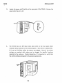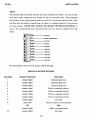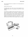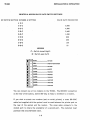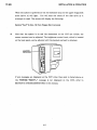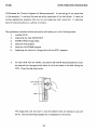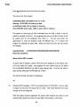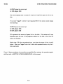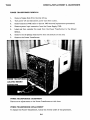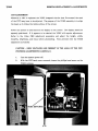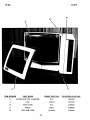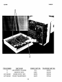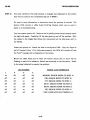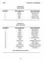
1
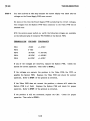
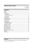
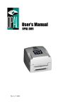
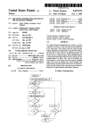
TELEVIDEO TS 803 MICROCOMPUTER SYSTEM
SERVICE MANUAL
600P*****
Prepared by:
Xerox Corporation
Xerox Service Business
Service Education & Customer Support
1341 W. Mockingbird Lane
Dallas, Texas 75247
PRELIMINARY SEPTEMBER 1983
TABLE OP CONTENTS
SECTION 1
INSTALLATION
SECTION 2
CP/M OPERATING PROCEDURES
SECTION 3
2-1
LOADING
2-2
DISPLAYING THE DISK DIRECTORY
2-3
FORMAT
2-5
PIP
2-6
COPYDISK
2-7
STAT
REMOVAL/REPLACEMENT & ADJUSTMENTS
3-1
FLOPPY DISK DRIVE
3-3
SYSTEM PWB
3-5
POWER SUPPLY PWB
3-6
POWER TRANSFORMER
3-7
POWER ON/OFF SWITCH
3~8
VIDEO PWB
3-10
CRT
SECTION 4
PARTS
SECTION 5
TROUBLESHOOTING
5-2
STEP 1
5-19
APPENDIX A COMMON OPERATOR PROBLEMS
SECTION 6
FUNCTIONAL THEORY OF OPERATION
SECTION 7
CONNECTOR PIN ASSIGNMENTS
TS 803 isa registered trademark of TeleVideo Systems, Inc. CP/M is a registered
trademark of Digital Research, Inc.
Corporation.
Z80A is a registered trademark of ZILOG
SECTION 1 INSTALLATION
INSTALLATION
TS 803
The following procedures are required for the installation of the TeleVideo TS 803
microcomputer.
1.
Carefully unpack all of the components received by the customer. The items
received should include the following:
TS 803 which includes the keyboard, CRT/disk drive assembly, and power cord.
Documentation which should include the "TS 803 Computer System User's
Manual", "TS 803 Quick Setup Guide", and the CP/M Software License
Agreement and Registration Card.
One diskette labeled "TS 803 CP/M" (this is the system disk and contains the
operating system).
One envelope which contains a' fuse marked .75A 250V (this is for the 230V
power supply which is used if the system is operated outside of the U. S.).
TeleVideo recommends for optimum performance, the TS 803 should be
located at least five feet from other computing equipment, electrical
appliances, or equipment such as elevators, radio transmitters, and television
sets that generate magnetic fields.
2.
Place the TS 803 and the keyboard at the location where it is to be used. Plug
the telephone-type coiled cable that is connected to the front of the TS 803
into the phone jack outlet on the back of the keyboard as shown in the diagram
below.
1-1
INSTALLATION
4.
3.
Locate the power on/off switch on the rear panel of the TS 803. Be sure the
power switch is set to off.
4.
The TS 803 has one DIP (dual inline pin) switch on the rear panel which
controls various functions of the microcomputer. This switch is labeled "Sl".
Sl is set by TeleVideo before the system was shipped.
Some of the switch
'settings are required while others can be changed for specific functions
required by the customer. During installation, it is important to verify that
the switch settings correspond to the system requirements.
DlPawm:tt
(1W1)
1-2
INSTALLATION
TS 803
NOTE:
The sections (10) of the DIP switches are small individual switches. The top of each
lever has a small recess that will accept the tip of a ball point pen. When changing
the position of any switch, gently push the switch to the desired position with. a pen,
and then give the switch a second push to ensure it is seated properly in the position
you have chosen. NEVER USE A PENCIL TO CHANGE THE SWITCH SETIINGS. If
any of the lead particles from the pencil fall into the switch a malfunction may
occur.
EITHER
Q
~.;.;;;;.;.;.-----NOTUSED
CJ)
OPEN
t-=-=::.:.:.....-----GREEN
ON BLACK SCREEN
co
r---~-----NOT
,..
ClOSED
'-===;"""'-----60
HERTZ
fD
t-==~-----ReoUIRED
It)
...-:;=~-----ReoUIRED
•
~~-----REQUIRED
CO)
~~----- BAUD RATE
N
CLOSED
..-=-==:...----BAUD RATE
EITHER
USED
CLOSED
CLOSED
CLOSED
CLOSED
CLOSED
~~~----BAUD
RATE
The following is a list of the SI section switch settings.
SWITCH SI SECTION SETTINGS
SECTION
DEFAULT SETTING
FUNCTION
1
closed (right)
Controls baud rate
2
closed (right)
Controls baud rate
3
closed (right)
Controls baud rate
4
closed (right)
This is a required position
5
closed (right)
This is a required position
6
closed (right)
This is a required position
7
closed (right)
This is a required position
8
closed (right)
Not used
9
open (left)
Green on black screen (default)
OR
FOR
closed (right)
Black on green screen
closed (right)
Not used
10
1-3
INSTALLATION
TS803
Note that sections 4,5,6 and 7, are required to be in the closed position for
correct operation.
Sections 8 and 10 are not used.
By changing section 9 from closed
~o
open, the screen appearance can be
changed from green letters on a black backround to black letters on a green
backround.
The TS 803 and any peripheral (modem, printer) device connected to it must
operate at the same speed in order to work properly. This speed is called the
baud rate. Sections 1,2, and 3 are used to control the baud rate for different
printer and modem applications. Before connecting a peripheral device to the
system you will have to know the baud rate of that device (it is usually
included with the installation procedures of the specific unit).
To achieve
different baud rates, the sections would be changed as listed on the next page.
1-4
INSTALLATION &: OPERATION
TS803
PRINTER &: MODEM BAUD RATE SWITCH SETTINGS
)IP SWITCH SECTION NUMBER & SETTING
BAUD RATE PRODUCED
-123
--
CCC
9,600
OCC
4,800
COC
2,400
ooc
ceo
oco
1,200
COO
150
000
75
600
300
LEGEND
C = Switch closed (right)
o
=Switch open (left)
EITHER
NOT USED
OPEN
GREEN ON BLACK SCREEN
CD
EITHER
NOT USED
,...
CLOSED
co
ClOSED
Q
Q)
It)
'If
CO)
N
60 HERTZ
REQUIRED
ClOSED
REQUIRED
CLOSED
REQUIRED
ClOSED
BAUD RATE
CLOSED
BAUD RATE
ClOSED
BAUD RATE
You can connect one or two modems to the TS 803. The RS-232C connection
on the rear of the system, labeled RS-232, is ready to interface to a modem.
If you wish to· attach two modems (and no serial printer), a cross RS-232C
cable (not supplied with the system) must be used between the printer port on
the rear of the system and the modem.
The cross cable connects to the
modem port to create the availablity of a second port.
purchase this cross RS-232C cable.
1-5
The customer must
INSTALLATION & OPERATION
TS 803
5.
The two slim line floppy disk drives contain pieces of cardboard to protect
them during shipping. To remove the cardboard rotate each disk drive latch
towards the screen and slide the cardboard out of the drive.
DRIVE II-t----H-"""",,
6.
Plug the power cord into the rear of the TS 803 and then into the wall
receptacle •
7.
The TS 803 is powered on by pressing the power switch on the rear of the unit
to the ON position.
1-6
INSTALLATION &: OPERATION
TS 803
.
"
When the system is ""powered on the red indicator lamp on the upper floppy disk
drive (drive A) will light.
You will hear the sound of the disk drive as it
attempts to "read. The screen will display the following:
System "boot" (I-Rev. X) from floppy disk in process
8.
Now that the system" is on and the characters on the CRT are visible, the
screen contrast can be adjusted. The brightness control knob, which is located
on the back panel, can be adjusted until the desired contrast is obtained.
If any messages are displayed on the CRT other than what is listed above or
the "SYSTEM ''BOOT''••• '' message is not displayed on the CRT, refer to
SECTION 5 (TROUBLESHOOTING) in this manual.
1-7
SECTION 2 CP/M OPERATING PROCEDURES
TS 803
CP/M OPERATING PROCEDURES
CP/M stands for "Control Program for Microcomputers". It controls all of the operations
in the computer. It controls the read and write operations of the disk drives. It loads the
. various applications programs that are run and supervises their execution.
It organizes
data for communications to a printer or modem.
The procedures contained within this section will assist you in the following areas:
1.
Loading CP/M
2.
Displaying the disk DIRECTOR Y
3.
FORMATTING Floppy Disks
4.
Using the PIP program
5.
Using the COPYDISK program
6e
Displaying the status of a floppy disk with the STAT program.
1.
To load CP/M into the TS 803, the system disk (CP/M Operating System) must
be inserted into the upper drive (drive A) with the labels on the disk facing the
CRT. Close the disk drive latch.
Duvr LATCH
-+--!+-"f'
The floppy disk unit will start to read the diskette (the red indicator lamp will
be lit) and the following message will be displayed on the screen.
2-1
CP/M OPERATING PROCEDURES
TS 803
TeleVideo System TS 803 VX.X
(c) 1983 TeleVideo Systems, Inc.
XXK CP/M version X.X
This message indicates that CP/M (the operating system) is now loaded and the
system is waiting'for your instructions.
A> is the "system prompt" and indicates that the operating system (CP/M) is
ready and waiting for your instructions. The letter A indicates which diskette
drive is being used. TeleVideo refers to this as the "logged drive".
To request the system to change to the lower or B floppy disk drive, you type
b: after the prompt.
A>b:
Then press the return key. The following will be displayed on the CRT.
B>
This indicates that the system now has the lower (B) floppy disk drive selected.
The red indicator light on the front of the drive will be lit.
2.
The system disk contains a list of the programs available for the user in a file
called "DIRn (DIRECTORY). You can request the system to display this list on
the CRT. With the prompt displayed on the screen (A>or
B~
and the system
disk in the selected drive type the word DIL
A>DIR
Then press the return key. The system disk DIRECTORY will be ,displayed on
the screen and appear similar to the following.
2-2
CP/M OPBRATING PROCEDURBS
'1'8803
FORMAT COM
STAT COM
COPYDISKCOM
PIP
COM
The directory contains many more programs than we have listed here .. These
displayed are the more common programs that you may use while servicing the
system.
The names of the programs (PIP, FORMAT, STAT, COPYDISK) are followed by
their filetype extension (COM). The extension identifies the types of files in a
directory.
3.
Before you can use a floppy disk in your system it must be "FORMATTED".
The FORMAT program is the process the system uses to prepare the disk to
receive information. In the FORMAT program, the disk drive writes data on
all of the tracks on the disk.
The drive then reads all of the data it has
written to verify if it is correct. The FORMAT procedure is as follows •.
With the system disk in drive A (upper drive) and the system prompt (A":::::»
displayed, load a floppy disk to be formatted into drive B (lower drive).
Type FORMAT, and press the return key.
The following message will be
displayed on the CRT.
A> FORMAT (press the return key)
FLOPPY DISK FORMAT VX.X
(c) 19XX TeleVideo Systems, Inc.
1. TS 801/802 AS USBR STAND ALONB
2. TS 801/802 AS SATBLLITB USBRSTATION
3. TS 802H AS STAND ALONB/SATBLLITB USERSTATION
4. TS 803 AS STAND ALONE
5. TS 803 AS SATBLLITB USBRSTATION
6. TS 806
1. BXIT
2-3
CP/M OPERATING PROCEDURES
TS803
Select system configuration option by number
The system is requesting you to indicate what type of TeleVideo system you
are using and how it is used (in a customer location you would have to ask the
operator for this information). In an example, we will indicate the TS 803 is a
stand alone microcomputer. We would select option 4.
4 (you do not have to press the return key after this entry)
The screen would then display.
DRIVE? (A or B, ESC to abort.)
The system requests you to indicate which drive contains the floppy disk to be
formatted. If you wish to stop the procedure press the ESC (ESCAPE) key. If
you have placed the system disk in drive A you will want to format a disk in
drive B. Type B.
B (you do not have to press the return key after this entry)
This screen will then display:
Insert a diskette into fioppy disk drive B
Press RETURN when ready. (ESC to abort.)
Again you are given the option to stop the procedure.
If you have already
loaded the floppy disk into drive B press the return key.
The
screen will
display:
formatting ••••••••••
As each track is formatted a new marker (.) will appear after the word
formatting. The screen will then display:
Formatting Completed.
2-4
CP/M OPERATING PROCEDURES
TS803
Drive? (A or B. ESC to abort.)
The format process has completed for the disk in drive B and the system is
asking if you wish to format another disk.
If you do not wish to format
another disk at this time, press the ESCape key. The
follo~ing
will be
displayed:
End of Execution
A>
The program is ended and you are returned to the system prompt.
4.
The PIP program is used to copy files from one disk to another disk. PIP is an
abbreviation for "Peripheral Interchange Program"o
Actually, the PIP
command can transfer files between any of the hardware components.
For
example, you can use PIP to send a file to a printer for a hard copy of your
work. We will discuss how to use PIP at this time to copy a file from one disk
to another.
With the system prompt displayed and a formatted disk in drive B, type PIP
and then press the return key. The following will be displayed on the CRT:
A> PIP
*
The asterisk symbol (*) indicates that you have successfully entered the PIP
program. To copy the FORMAT program from disk A to disk B we would enter
the following.
* B:=A:FORMAT.COM (then press the return key)
In this series of instructions we are telling the system to copy a program to
the disk in drive B:, from drive A:, and the name of the program is FORMAT,
with an extension of .COM. When the program was "PIPped" to drive B, the
would again be displayed.
2-5
*
CP/M OPERATING PROCEDURES
TS803
If you press the return key again, the system will exit the PIP program and the
system prompt will be displayed.
You can now use the DIR command to
examine disk B to see if PIP worked correctly.
A>B: (press the return key)
B> DIR (press the return key)
B: FORMAT COM
B>
The directory screen displays the FORMAT program we sent via the PIP
program. The PIP program can be used to transmit any program as long as you
enter the information in the sequence listed.
5.
If you wish to copy an entire disk you would use the COPYDISK program. With
the system prompt displayed type the following:
K? COPYDISK (press the return key)
The screen will respond with:
A>COPYDISK
COPYDISK (TS 803) VX.X
(c) 19XX TeleVideo Systems, Inc.
Source Drive: (ESC to abort).
The system is asking you to respond to which drive the programs will be copied
from. You would type an A or use the ESCape key to stop the program. The
screen would then respond with:
Destination Drive: (ESC to abort.)
-You are now asked which disk drive should the programs be copied to. You are
also again given an opportunity to stop the procedure. Enter the destination
drive.
2-6
-CP/MOPBRATING PROCBDURBS
TS803
B (do not press the return key after this entry)
The screen will then display:
CONFIRMATION: COPYDISK from "A" to "B".
Warning: COPYDISK will destroy all data
on destination disk with no chance of recovery.
Press RBTURN when ready. (BSC to abort, BAR to restart.)
The system is informing you that everthing from the disk in drive A will be
copied to the disk in drive B. Any programs that are on the disk in drive B will
be copied over by the programs from drive A.
You are also given the
opportunity to stop the program using the ESCape key, or to restart the
program by pressing the space BAR. When you press the return key the screen
will display:
Copying (Track) - -) 0123456789012345678901234567890123456789
Disk Copy Completed
Source Drive: (BSC to abort.)
As each track is copied a number (0-9) will be be displayed on the screen until
all of the tracks are copied. The program will then restart and you are asked
for the SOURCE DRIVE if you wish to copy another disk. If you do not wish to
copy another disk press the ESCape key to stop.
The system prompt will again be displayed.
A>
6.
Using the STAT program. STAT is an abbreviation for STATUS. It can be used
to diplay on the screen the space left on a disk. This would indicate how much
storage is left for programs.
With the system prompt displayed, the system disk inserted into drive A, and
another disk inserted into drive B, enter STAT followed by a return keyo
2-7
CP/M OPERATING PROCEDURES
TS803
A>STAT (press the return key)
A: R/W, Sp~c~: XXK
The screen .pisplays that a number of K bytes of read/write space is left on the
disk.
If we were "logged" to drive B and requested ST AT the screen would display
the following:
8>STAT (press the return key)
A: R/W, Space: XXK
8: R/W, Space: XXK
XX represents the amount of space left on the disk.
This number will vary
depending upon the size of the programs resident on the disk at the time the
status was checked.
Notice that if B drive was selected you are given the status of the A and B
drives. When you "logged" onto the A drive and requested status, only the A
drive was listed.
If any of these procedures do not perform as specified first attempt the procedure again,
and then refer to SECTION 5 (TROUBLESHOOTING) in this manual.
2-8
SECTION 3 REMOVAL/REPLACEMENT c!c ADJUSTMENTS
REMOVAL/REPLACEMENT &: ADJUSTMENTS
TS 803
rhe following procedures contain the removal/replacement and adjustment procedures for
the TeleVideo TS 803 microco}nputer system.
FLOPPY DISK DRIVE REMOVAL
1.
Remove floppy disks from the disk drives.
2.
Turn power off and disconnect power cord from outlet.
3.
Remove (3) phillips head screws from the case bottom as shown.
4.
Lift case bottom out, up, and off of brackets.
(11(((((((((((((((
(((((((((((tttlitt
-
PHILLIPS HEAD SCREWS
3-1
RBMOVAL/RBPLACBMBNT &: ADJUSTMBNTS
TS803
NOTE:
Before you remove any 'cables from a connector be s,ure to note the
orientation (red stripe or position of connector) to ensure the cable is
reconnected correctly.
5.
Remove floppy disk drive data cable from connector P7 on the System PWB.
6.
Remove (4) wire power input plug and "stab-on!' ground connector from each
disk drive (you may also need to cut and remove tie wrap).
7.
Remove (7) phillips head screws from disk drive assembly frame.
8.
Lift disk drive assembly and frame out of cover.
9.
Remove (4) phillips head screws securing each disk drive to bottom of frame
assembly.
FLOPPY DISK DRIVE ADJUSTMENT
There are no adjustments within the floppy disk drives at this time.
FLOPPY DISK DRIVE REPLACEMENT
To replace the floppy disk drives, follow the reverse order of this procedure.
3-2
REMOVAL/REPLACEMENT & ADJUSTMENTS
TS803
SYSTEM PWB REMOVAL
1.'
Remove floppy disks from the disk drives.
2.
Turn power off and disconnect power cord from outlet.
3.
Remove (3) phillips head screws from case bottom as shown.
4.
Lift case botto m out, up, and off of brackets.
II tl(((((((((((((~
((((((((((((1(1111
pmLLIPS HEAD SCREWS
3-3
REMOVAL/REPLACEMENT & ADJUSTMENTS
TS803
5.
6.
Disconnect power connector P5 and video connector P6.
7.
Disconnect disk drive data cable P7.
8.
Remove (4) phillips head screws securing System PWB to frame.
9.
Remove System PWB.
Remove keyboard connector P11.
.
.. ' ...
~
---~--
SYSTEM PWB ADJUSTMENT
There are no adjustments to the System PWB at this time.
SYSTEM PWB REPLACEMENT
To replace the System PWB follow the
rever~e
3-4
order of this procedure.
TS803
REMOVAL/REPLACEMENT & ADJUSTMENTS
POWER SUPPLY PWB REMOVAL
1.
Remove floppy disks from the disk drives.
2.
Turn power off and disconnect power cord from outlet.
3.
Remove System PWB (refer to System PWB removal/replacement procedure).
4.
Label and disconnect leads connected to terminal strip on Power Supply PWB.
5.
Disconnect input power connector to Power Supply PWB.
6.
Remove the (2) phillips head screws from each of the power transistors.
7.
Remove the (4) phillips head screws from the Power Supply
8.
Remove the Power Supply PWB and power transistors from the unit.
P~B.
-.--~--
POWER SUPPLY PWB ADJUSTMENT
There are no adjustments to the Power Supply PWB at this time.
POWER SUPPLY PWB REPLACEMENT
Replace the Power Supply PWB and power transistors using this procedure in reverse
order.
3-5
REMOVAL/REPLACEMENT &: ADJUSTMENTS
TS803
POWER TRANSFORMER REMOVAL
flo~py
1.
Remove
disks from the disk drives.
2.
Turn power off and disconnect power cord from outlet.
3.
Remove System PWB (refer to System PWB removal/replacement procedure).
4.
Remove power input connector from the Power Supply PWB.
5.
Label and then unsolder the leads from the Power Transformer to the SELect
SWitch.
6.
Remove the (4) phillips head screws from the bottom of the unit.
7.
Remove the Power Transformer.
POWER TRANSFORMER ADJUSTMENT
There are no adjustments to the Power Transformer at this time.
POWER TRANSFORMER REPLACEMENT
To replace the Power Transformer, follow the reverse order of this procedure.
3-6
REMOVAL/REPLACEMENT & ADJUSTMENTS
TS 803
POWER ON/OFF SWITCH REMOVAL
1.
Remove floppy disks from the disk drives.
2.
Turn power off and disconnect power cord from outlet.
3.
Remove System PWB (refer to System PWB removal/replacement procedure).
4.
Label and unsolder the (2) leads to the Power On/Off Switch.
5.
Remove the (2) phillips head screws from the Power On/Off Switch.
6.
Remove the Power On/Off Switch from the back panel of the system •
.
",
,
.. ..
"
'
---~-.
POWER ON/OFF SWITCH ADJUSTMENT
There are no adjustments to the Power On/Off Switch at this time.
POWER ON/OFF SWITCH REPLACEMENT
To replace the Power On/Off Switch, follow this procedure in the reverse order.
3-7
REMOVAL/REPLACEMENT &: ADJUSTMENTS
TS803
VIDEO PWB REMOVAL
1.
Remove floppy disks from the disk drives.
2.
Turn power off and disconnect power cord from outlet.
NOTE:
EXERCISE CAUTION WHEN WORKING IN THE AREA OF THE CRT.
HIGH VOLTAGES ARE PRESENT.
3.
Remove the System PWB (refer to the System PWB removal procedure).
4.
Remove the phillips screw that holds the ground connections to the frame (this
is located above the access hole to the left of the Power Supply PWB).
5.
Attach one end of a meter lead to the metal frame on the Video PWB.
6.
Attach the other end of the meter lead to a flat blade screwdriver.
METAL FRAME
RUBBER BOOT
3-8
REMOVAL/REPLACEMENT c5c ADJUSTMENTS
TS803
7'-
To discharge the CRT, slide the flat blade screwdriver (which is grounded by
the connection of the meter lead) under the rubber boot of the high voltage
lead on the CRT.
Ensure you have made connection with the metal prongs
inside of the boot (you mayor may not hear a sparking sound when connection
is made).
8.
The metal prongs which connect the high voltage lead to the CRT are in the
shape of a horseshoe. Squeeze the rubber boot towards the center to release
the metal prongs from the socket.
You may have to slide the rubber boot
away from the CRT to remove this connection. If you need to move the boot,
place the grounded screwdriver directly on the metal prongs to ensure the
CRT is discharged. Remove the metal prong connector from the CRT.
9.
Disconnect the CRT socket. This is a small PWB connected to the base of the
CRT. The pins on the base of the CRT are easily damaged. Remove the CRT
socket carefully.
10.
Remove the (2) phillips head screws from the base of the Video PWB.
11.
Slide the Video PWB away from the CRT approximately 1 inch to gain access
to the connectors.
Remove the DC POWER connector J11, the YOKE
connector P1, and the VIDEO connector from the Video PWB.
12.
Slowly slide the Video PWB away from the CRT until you can see the stab-on
ground connector. This connector is located in the lower left corner of the
CRT. Disconnect the stab-on ground connector.
13.
Remove the Video PWB.
VIDEO PWB ADJUSTMENT
There are (5) adjustments which may be required when a new Video PWB is installed.
Four of the adjustments (bright, height, linearity, and focus) are located on the front
of the PWB. The adjustment coil for width is located on the rear of the PWB behind
the metal shield. Non-ferrous alignment tools are required for
~hese
adjustments.
There are currently no specified standards for these adjustments. Whenever a Video
PWB is replaced, examine the display on the CRT. If adjustment is required, use a
non-ferous alignment tool and adjust the Video PWB so that the display is centered
(both vertically and horizontally with !!Q borders) on the screen with a clear image.
VIDEO PWB REPLACEMENT
To replace the Video PWB follow this procedure in the reverse order.
3-9
REMOVAL/REPLACEMENT &: ADJUSTMENTS
TS803
CRT (Cathode Ray Tube) REMOVAL
1.
Remove floppy disks from the disk drives.
2.
Turn power off and disconnect power cord from outlet.
NOTE:
EXERCISE CAUTION WHEN WORKING IN THE AREA OF THE CRT.
HIGH VOLTAGES ARE PRESENT.
3.
Remove the System PWB (refer to the System PWB removal procedure).
4.
Remove the Video PWB (refer to the Video PWB removal procedure).
5.
Use a wide flat blade screwdriver to carefully pry off the bezel from the front
of the CRT.
6.
Using a 5/16 inch wrench carefully remove the (4) hex bolts which hold the
CRT to the frame. SUPPORT THE CRT WHILE REMOVING THESE BOLTS.
7.
Carefully lift the CRT out of the frame assembly.
3-10
REMOVAL/REPLACEMENT &: ADJUSTMENTS
TS 803
CRT ADJUSTMENT
Whenever a CRT is replaced the YOKE (magnetic device that fits around the neck
of the CRT) may have to be adjusted. The purpose of the YOKE assembly is to align
the beam as it strikes the inside surface of the screen.
Power the system on and examine the display on the screen.; The display should be
~quarely
positioned. If it appears to be slanted the YOKE will require adjustment.
Refer to the Video PWB adjustment procedure and adjust the height, width,
linearity, brightness, and focus before proceeding.
Then proceed with the YOKE
adjustment as follows:
CAUTION - HIGH VOLTAGES ARE PRESENT IN THE AREA OF THE CRT.
PERFORM ADJUSTMENTS CAREFULLY.
1.
Turn the system power off.
2.
With the CRT back cover removed, loosen the phillips head screw on the
YOKE retainer.
3-11
RBMOVAL/RBPLACBMBNT c!c ADJUSTMBNTS
TS 803
3.
Grasp the plastic collar below the YOKE retainer and rotate the YOKE
in the direction opposite of the slant of the screen
4.
'Tighten the phillips head screw.
5.
Power the system on and verify the image on the screen is correct. If it
is still not squarely positioned repeat this procedure.
CRT REPLACEMENT
To replace the CRT follow this procedure in the reverse order. After replacement
of the CRT, the YOKE and VIDEO PWB adjustments should be checked.
3-12
SECTION 4 PARTS
PARTS
TS803
1
3
5
ITEM NUMBER
PART NAME
XEROX PART NO.
TELEVIDEO PART NO.
NOT SHOWN
POWER CORD
117N55
2291100
1
ON/OFF SWITCH
N/A
2097300
2
VIDEO PWB
140N230
2226900
3
BOTTOM ARM CASE
·101N104
2189200
4
'FUSE HOLDER
N/A
2097200
5
POWER INPUT SOCKET
N/A
2150100
4-1
PARTS
TS 803
6
ITEM NUMBER
PART NAME
XEROX PART NO.
TELEVIDEO PART NO.
6
KEYBOARD
110N53
2183700
NOT SHOWN
THUMB WHEEL
20W26
2218800
4-2
PARTS
TS 803
12
10
ITEM NUMBER
PART NAME
XEROX PART NO.
TELEVIDEO PART NO.
8
KEYBOARD COIL HARNESS
N/A
2005700
9
CRT
128N12
2218700
10
MAIN· CASE
N/A
2188500
11
BEZEL
55Nll
2188800
12
TOP ARM CASE
101N103
2189100
4-3
.
PARTS
TS 803
14
13
ITEM NUMBER
PART NAME
XEROX PART NO.
TELEVIDEO PART NO.
13
DRIVE SIGNAL HARNESS
N/A
2007301
14
DISKETTE DRIVE
23N27
2221300
NOT SHOWN
POWER SUPPLY PWB
105N76
2227500
NOT SHOWN
POWER TRANSFORMER
105N75
2227400
4-4
PARTS
TS 803
18·
17
ITEM NUMBER
PART NAME
XEROX PART NO.
TELEVIDEO PART NO.
17
POWER HARNESS
N/A
2008700
18
CRT BACK COVER
N/A
2188300
19
PROCESSOR PWB
140N229
2226000
4-5
SECTION 5 TROUBLESHOOTING
TROUBLESHOOTING
TS803
This section of the service manual will assist you in repairing problems within the
TeleVideo TS 803. The procedures are "directive".
Directive means you will be asked
questions and then depending upon your answer you will be given directions to help you in
each phase of troubleshooting. Always start at STEP 1 of the troubleshooting procedures.
It is designed to give you a step-by-step set of procedures to help you resolve problems.
For replacement or adjustment of components as indicated in this section, refer to the
REMOVAL/REPLACEMENT & ADJUSTMENT procedures located in SECTION 3 of this
manual.
PLEASE NOTH:
The troubleshooting procedures contain recommended replacement parts
for the correction of problems. If the recommended part replacement
does not correct the problem, reinstall the old part and continue
troubleshooting.
5-1
TROUBLESHOOTING
TS 803
STEP 1
With the power on/off switch pressed to the off position, visually inspect the
unit for obvious problems (broken components, disconnected cables, etc.).
Refer to Appendix A (COMMON OPERATOR PROBLEMS & CORRECTIVE
ACTIONS) if the problem appears to be user or applications related.
Push the power on/off switch to the on position.
Is the message "System "boot" (l-Rev. X) from floppy disk in progress"
displayed on the screen within (30) seconds (turn the contrast knob to ensure it
has not been adjusted incorrectly)?
When the system displays this message it indicates that the power supply
. voltages are within tolerance.
It also indicates that the basic start-up
diagnostics (which is contained in the system ROM) has completed without
finding an error.
If this message is displayed, refer to STEP 2.
If
the
message
"HARDWARE
ERROR
(XXX);
CONTACT
YOUR
DISTRIBUTOR", or an error code such as "OOOO-07FF" is displayed on' the
screen, refer to STEP 7.
If there is nothing displayed on the screen, refer to STEP 8.
5-2
TROUBLESHOOTING
TS803
STEP 2
Is the display on the screen clear and readable?
If so, this indicates that the System PWB, Video PWB, and CRT circuitry which
control the screen displays are functioning correctly.
If the display is acceptable, refer to STEP 3.
If the display is not clear and readable, the problem is associated with the
video circuits.
The components which make up this circuit include the
following.
VIDEO PWB
SYSTEM PWB
CRT
Refer to the REMOVAL/REPLACEMENT & ADJUSTMENTS section. in this
manual for the VIDEO PWB procedures. Adjust the VIDEO PWB as indicated in
the adjustment procedures.
If the adjustment procedure does not correct the problem replace the VIDEO
PWB.
Be sure to perform the adjustments when installing the new VIDEO
PWB. Check the system for correct operation.
If the problem is not corrected replace the SYSTEM PWB. Check the system
for correct operation.
If the problem is not corrected replace the CRT.
Be sure to perform the
VIDEO PWB adjustments after replacing the CRT.
Check for correct
operation.
When the problem is corrected, refer to STEP 1 to verify the entire system is
functioning correctly.
5-3
TS 803
TROUBLESHOOTING
)'rEP 3 ' Ask the customer for the CP/M operating system disk and insert it into drive
A (upper drive) with the labels facing the screen. Turn the disk drive latch to
the closed position. Within (30) seconds is the following message displayed on
the screen?
TeleVideo Systems TS 803 VX.X
(c) 19XX TeleVideo Systems, Inc.
XXK CP/M version X.X
This message displayed on the screen indicates that CP1M is loaded, waiting
for your commands, and that no apparent problems have been found at this
time.
If this message is displayed on your screen, refer to STEP 4.
If this message is not displayed on the screen, there is a problem with the
System Disk (software), or System PWB.
Load a different system disk (not a copy of the first disk) into the system and
press the RESET key while holding down the CONTROL key. If the message is
correctly displayed the problem is corrected.
If this did not correct the problem, replace the System PWB. Check to see if
the problem is corrected.
When the problem is corrected, refer to STEP 1 for further check to determine
if the system is functioning correctly.
5-4
TROUBLESHOOTING
TS 803
STEP 4
With the "system prompt
(~)
displayed on the screen, type DIR (DIRectory).
The directory displayed on the screen indicates that the keyboard and
associated circuitry on the System PWB are functioning
correct~y.
This also
indicates that the system has the ability to read from a diskette, process, and
display information.
If the DIRectory was displayed on the screen, refer to STEP 5
If the directory was not displayed on the screen, this indicates a proble m with
the keyboard, System PWB, or System Disk (software).
Load a different system disk into the system and press the RESET key while
holding down the CONTROL key.
If the message is correctly displayed the
proble m is corrected.
If the problem is not corrected press and hole the CONTROL key and then
press the RESET key.
The screen should clear and then display the system
"boot" message. If this action occurs, the keyboard is sending a signal to the
System PWB and the System PWB is responding to the command.
If this does not occur, ensure the keyboard cable is not damaged and is
connected correctly to the keyboard and to the System PWB. If this does not
correct the problem, replace the keyboard.
Check the system for correct
operation.
If the problem is still not corrected, the System PWB is not operating
correctly.
Replace the System PWB and verify the system is operating
correctly.
When the system is functioning properly, refer to STEP 1 for a complete
checkout of the syste m.
5-5
TS803
STEP 5
TROUBLESHOon1NG
'·Using SECTION 2 CP/M OPERATING·PROCEDURES in this manual as
reference, perform the following procedures.
A.
FO RMA T a blank or previously used floppy disk.
B.
PIP a file from the system disk to the formatted disk.
Use the
DIRectory command to ensure the file was copied.
C.
Using the COPYDISK program, copy the system disk to the formatted
disk. Use the DIRectory command to ensure the contents of the system
disk was copied to the formatted disk.
The successful completion of these programs indicates the hardware is
performing correctly at this time.
If these programs functioned correctly, refer to STEP 6.
If any of these programs did not complete successfully, one of the following
items is malfunctioning.
The System Disk
The formatted disk
The System PWB
The floppy disk drive(s}.
Load a different system disk (not another copy) into the system and attempt
to run the program again. Verfiy that the error has been corrected.
If the problem is still present, use a different blank disk and attempt the
procedures again. Verify the error has been corrected.
If an "FDC" error message was displayed during the failing procedure, the
problem is the System PWB or the floppy disk drive/cables.
Replace the System PWB. Verify correct operation.
If the problem was not corrected, replace the floppy disk drive cables and then
the drives. Verify the system is operating correctly.
Once
th.~
problem has been corrected, refer to STEP 1 to complete the
checkout of the system.
5-6
TROUBLESHOOTING
TS803
STEP 6
The .' system' seems to be . operating correctly at this time.,
Question the
customer as to the original symptoms and try to recreate them.. Ensure you
are using the floppy disks the 'customer was using when the failure occurred.
For common operator/software related problems and solutions, refer to
APPENDIX A in this section.
If the original problem was not software related, and appears to be corrected,
return the system to the customer.
5-7
TROUBLESHOOTING
TS 803
STEp·7
You have arrived at this step because the screen displayed the message
"HARDWARE ERROR (XXX); CONTACT YOUR DISTRIBUTOR", or an error
code such as "OOOO-07FF" is displayed on the screen.
These messages indicate the internal system diagnostics (stored in ROM) have
found a problem when the system was· powered on.
Read the following
paragraphs and follow the directions which correspond with the indications
diaplayed on your system.
If the error· message is "DMA" or a code "OOOO-07FF" or "2000-3FFF" is
displayed on the screen, refer to STEP 10.
If the error message is "CTC" refer to STEP 11.
If the error message is "P3ER, P4ER, SIO 11, SIO 12, or PIO" refer to STEP
12.
If the error message is "FDC" refer to STEP 13.
If the error message is not listed above, refer to STEP 14.
5-8
TROUBLESHOOTING
TS803
STEP 8 . : . You· have' arrived at this step· because you .indicated that there was nothing
displayed on the
sc~een
when the system was powered on.
Verify that the power cord is connected to a known good receptacle (use your
meter to test or plug another device into the outlet). Also verify that the fuse
on the back panel is not open.
Check system operation.
If either of these tests corrected the problem, refer
to STEP 1. If the problem is not corrected, continue reading the next line.
In STEP 1 you should have checked the contrast knob to ensure it was adjusted
correctly. If you have not, check the adjustment at this time.
Check system operation. If the contrast knob corrected the problem, refer to
STEP 1. If the problem is not corrected, continue reading the next line.
Check the switch settings of DIP switch Sl (refer to the INSTALLATION
section of this manual for switch settings).
Ensure that section 9, which
controls the backround of the display, is fully actuated.
Move the switch to
the opposite position and then back to its original position.
Check system operation. If the DIP switch actuation corrected the problem,
refer to STEP 1. If the problem is not corrected, continue reading the next
line.
Power the syste m off.
Refer to
the
REMOVAL/REPLACEMENT &
ADJUSTMENTS section of this manual and follow the procedures for removal
of the FLOPPY DISK DRIVES. Do not remove the drives from the frame.
/
/
With the disk drives/frame assembly removed from the system, remove the (4)
screws securing the System PWB.
Disconnect the keyboard connector P11.
With the POWER and VIDEO connectors still connected, place the System PWB
on the top of the TS 803.
CONTINUED ON NEXT PAGE
5-9
TROUBLESHOOTING
TS803
Power" the System on and: verify the following"power"supply voltages with your
meter.
The terminal on the Power Supply PWB has the description of the
voltage and the terminal pin number printed next to each of the connections.
The following voltages should be available on the indicated terminal pin.
TERMINAL PIN VOLTAGE
TOLERANCE
(1) VID.B+
(70)VDC
+/-5VDC.
(2) -12V
-12VDC
+/- IVDC
(3) GND
o VDC
(4) +12V
+12VDC
+/- IVDC
(5) +12V
+12VDC
+/- IVDC
(6) +5V
+5VDC
+/- IVDC
(7) +5VDC
+5VDC
+/- IVDC
(8) +5VDC
+5VDC
+/- IVDC
(9) GND
o VDC
o VDC
(10) GND
If all the above voltages are correct, refer to STEP 9.
If the above voltages are incorrect, power the system off and unplug the power
input cord. Connect your meter leads to the (2) wires soldered to the power
on/off switch. Set your meter to read AC voltage of approximately 120 volts.
Plug the power cord in.
With the power on/off switch set to off, the meter should read approximately
120 VAC. Read the following paragraphs and find the set of conditions which
match the reading you have received.
If the voltage is not present, disconnect the power cord and check the wires to
the fuse holder and the power plug socket for unsoldered or broken
connections. If you find one of these conditions, repair the problem and check
the system for proper operation. Then refer to STEP 1. If the problem is not
corrected, continue reading on the next page.
5-10
TROUBLESHOOTING
TS 803
If· you -did not find abrokencconnection or unsoldered wire, the problem is
either the fuse holder or the input power connector assembly. Check each of
these components for open wires or damage.
Replace the defective
component. Check the system for proper operation. Then refer to STEP 1.
If the meter did read 120 VAC with the power on/off switch off, press the
switch to the on position. The meter should read 0 VAC. If the reading does
not change, the power on/off switch is open. Replace the power on/off switch
and then verify correct operation. Then refer to STEP 1.
If the meter did read 0 VAC when the power on was selected, the Power
Transformer is the problem.
Replace the transformer and verify correct
operation. Then refer to STEP 1.
5-11
TROUBLESHOOTING
TS 803
STEP 9
You have arrived aX this step because the screen display" was blank and the
voltages on the Power Supply PWB were correct.
We know at this time the Power Supply PWB is producing the correct voltages.
The voltages from the System PWB Video connector to the Video PWB will be
checked next.
With the system power switch on, verify the following voltages are available
on the indicated pins of connector P6 (VIDEO) on the System PWB.
TERMINAL PIN
VOLTAGE
TOLERANCE
PIN 1
.9VDC
+/-.5VDC
PIN 2
o VDC
PIN 3
.05 VDC
+/-.05 VDC
PIN 4
.25 VDC
+/-.25VDC
PIN 5
4.8 VDC
+/-.5VDC
If any of the voltages are incorrect, replace the System PWB.
Check the
system for correct operation. Then refer to STEP !.
If the voltages are correct, the problem is the Video PWB, the CRT, or
possibly the System PWB.
Replace the Video PWB and check for correct
operation. Refer to STEP 1 if the problem is corrected.
If the Video PWB does not correct the problem, a chance still exists the
System PWB is at fault.
Replace the System PWB and check for proper
operation. Refer to STEP 1 if the problem is corrected.
If the problem is still not corrected, replace the CRT.
operation. Then refer to STEP 1.
5-12
Check for proper
TS803
"STEP 10
TROUBLESHOcnnNG
You have arrived at this step because··the ··errormessage "DMA" or a code
"OOOO-07FF" or "2000-3FFF" is displayed on the screen.
These codes indicate the internal diagnostics (stored in ROM) have detected a
problem with the memory circuits located on the System PWB.
Replace the System PWB.
Verify correct operation of the system and then
refer to STEP 1.
5-13
TS
803
...
ISTEP 11
TROUBLESHOOTING
You have arrived at this step because the screen displayed the error message
"PTC" or you were referred here by STEP 14.
This message indicates an error was encountered by the internal diagnostics
(stored in ROM) at power on.
The error appears to be in the "COUNTER
T):MER CIRCUIT" which is located on the System PWB.
Replace the System PWB.
Verify correct operation of the system and then
refer to STEP 1.
5-14
.
TROUBLBSHOOTING
TS803
STBP 12 - You have arrived at this step because the 'error message "P4ER, SIO #1, SIO
#2, or PIO" was displayed on the screen or you were referred here by STEP 14.
This type of error indicates a problem was encountered by the internal
diagnostics (stored in ROM) with the interface ports of the system.
The
problem could be internal to the TS 803 or with the device connected to the
p~rt~
It is possible that DIP switch SI is not set correctly for the type of device
connected to the port. Ask the customer what the baud rate is for the device
connected to the port.
The baud rate switch settings are listed in the
INSTALLATION section of this manual. Verify the switches are correctly set.
If the switches are not correct, reset them, power the system on, wait (20)
seconds and then power the system on. If the system performs correctly, refer
to STBP 1.
If the problem was not corrected, continue reading the next
paragraph.
The next step is to use the diagnostic software located on the TV 803
Diagnostic Disk to isolate the problem.
Power the syste m on.
Insert the TS 803 Diagnostic Disk into drive A (upper drive). When the disk is
loaded the following message will be displayed on the screen.
TeleVideo System TS 803 VX.X
(c) 19XX TeleVideo Systems, Inc.
XXK CP/M version X.X
A>
Type STI and then press the return key.
CONTINUED ON THB NEXT PAGE
5-15
TROUBLESHOOTING
TS803
The SERIAL TEST for INTERFACE program will be loaded into the system.
The message "TEST SE~IAL MODEM PORT WITH LOOPBACK?" will be
displayed on the screen.
This test sends a signal fro~ the System PWB to the connector (RS-232) on the
back panel of the. TS 803.· . The signal will be "turned around" (sent back) to the
System PWB. If the System PWB sees a correctly retur.ned signal, the internal
circuitry is functioning prpperly.
If the signal returned is incorrect, the
circuitry is not functioning properly.
To turn the signal around, you will have to connect jumper wires to the RS-232
connector on the rear of the system. Connect jumper wires to the following
pins on the RS-232 connector (the pin numbers of this connector are indicated
in the diagram below).
PIN #2 to PIN #3
PIN #4 to PIN #5
PIN #6 to PIN #8
When you have installed the jumper wires, press the Y key.
The message "TEST DCD/DTR on MODEM?" will be displayed on the screen.
Press the RETURN key to indicate we do not want to run this test.
If the message "FAILED" appears on the screen, one of the test has not
completed successfully.
the test.
Verify the jumpers are installed correcly and rerun
If the test still fails, the System PWB is faulty and should be
replaced. After replacement, verify correct operation and refer to STEP 1.
If the test passes successfully with no failures indicated on the display, the
problem is with the cable to the external device or the device itself. These
devices must be repaired seperately and are not part of the TV 803 system.
Refer to STEP 1 to verify there are no other problems with the system.
5-16
TS 803
STEP 13
TROUBLESHOOTING
You have arrived at this step because the display indicated an error message
of "FDC" or you were ref erred here by STEP 14.
"FDC" is an abbreviation for Floppy Disk Controller..
When the system was
powered on, the internal diagnostics (stored in ROM) acknowledged a problem
in the floppy disk controller circuitry on the Syste m PWB, the data cables to
the floppy disk drives, or "the drives themselves. The internal diagnostics do
not have the ability to determine which of these items caused the problem.
Since the problem is with the Floppy Disk Controller circuitry, we can not load
the TS 803 Diagnostic Disk to assist us.
To repair this problem perform the following.
Refer to the REMOVAL/REPLACEMENT & ADJUSTMENTS section of this
manual.
Follow the procedure to remove the floppy disk assembly from the
system.
Do not disconnect the cables or remove the drives from the frame
assembly at this time.
Verify the cables (data and power) are connected properly and are not
damaged.
Replace if damaged and power the system on to determine if the
problem. is corrected.
If the problem was not corrected, replace the System PWB. Power the system
on to determine if the problem is corrected.
If this did not correct the problem, replace the floppy disk drives. Power the
system on to determine if the problem was corrected.
Once the problem is corrected, refer to STEP 1 for a complete check of the
system.
5-17
· TS
.. 803
STEP 14
TROUBLESHOOTING
You have arrived at this step because a -message was displayed on the screen
that was not listed in the troubleshooting list· in
We need to more information to determine
ST~P
where~he
7.
problem is located. The
System PWB contains 4 LEDs (Light Emitting Di:odes) which can be used to
assist us in troubleshooting.
Turn the system power off. Remove the (3) phillips head screws located below
the right side panel. Carefully lift the side panel up and off the catches. With
the cables to the floppy disk drives still connected, lay the side panel next to
the TS 803.
Power the system on. Watch the leds on the System PWB. They will flash on
and off several times. If all tests pass properly, the LEDs will remain off and
the "boot" message will be displayed on the screen.
Match the LEDs which are on when the failure occurs (one or more will be
flashing on and off to indicate a failure has occurred)
~o
the list below. Refer
to the steps indicated to resolve the problem.
LED NUMBER
ERROR AND REFERENCE
1
2
3
4
on
off
off
off
MEMORY ERROR REFER TO STEP 10
off
on
off
off
DMA ERROR REFER TO STEP 10
off
off
on
off
CTC ERROR REFER TO STEP 11
off
off
off
on
SIO #1 ERROR REFER TO STEP 12
on
on
off
off
SIO #2 ERROR REFER TO STEP 12
off
off
on
on
FDC ERROR REFER TO STEP 13
off
off
off
off
TEST COMPLETED SUCCESSFULLY
5-18
TROUBLESHOOTING
TS 803
APPENDIX A
COMMON OPERATOR PROBLEMS &: CORRECTIVE ACTIONS
The following is a list of common operator problems, software error messages, and
suggestions which may help the 'customer correct these problems.
PROBLEM
The system message "System "boot" (I-Rev. X) from floppy disk in
progress" appears on the screen but the CP1M diskette does not load the
operating system.
ACTION
Remove the diskette and reinsert it. Ensure the label is facing the CRT.
Reset the system by holding down the CONTROL key and then pressing the
RESET key. Try another syste m disk.
PROBLEM
The customer has changed the DIP switch settings but the system does not
respond to the new settings (a list of the switch settings is contained in the
installation section of this manual).
ACTION
After changing the switch settings, reset the system by holding down the
CONTROL key and then pressing the RESET key.
PROBLEM
The system does not respond to the keyboard (locked up).
ACTION
Remove the floppy disks from the unit.
Power the system off and then
wait (20) seconds. Power the system on.
PROBLEM
Escape and control functions do not operate as anticipated.
ACTION
Reenter commands paying particular attention to whether upper or lower
case characters are entered.
instructions.
5-19
Refer to the Users Guide for specific
TS 803
PROBLEM
ACTION
TROUBLESHOOTING
. "BDOS ERROR DIRECTORY-FULL" is displayed on the screen.
All of the directory entries have been used.
Use ERAse command to
remove old files.
PROBLEM
"BDOS ERROR DISK R/O" is displayed on the screen.
ACTION
An attempt was made to write on a disk before it was read.
Press the
CONTROL key and then the RESET key each time a new diskette is
inserted.
PROBLEM
"BDOS ERROR NO SPACE" is displayed on the screen.
ACTION
All of the formatted space on the disk is full. Use the ERAse command to
delete old files.
PROBLEM
"CME" is displayed on the screen.
ACTION
A direct command error or log on error was recognized.
Check that the
password was entered correctly and that it was a valid password. Recopy
programs from the "Mmmost" diskette (applications) if error did not result
from LOGON.
PROBLEM
"DPV" is displayed on the screen.
ACTION
The system recognized an error in the allocation of memory and files.
Recopy programs from the "Mmmost" diskette (applications).
PROBLEM
"SPD" or "SPF" is displayed on the screen.
ACTION
The disk which contains the files has had a spool operation overflow.
ERAse files that are not needed.
5-20
SECTION 6 FUNCTIONAL THEORY OF OPERATION
FUNCTIONAL THEORY OF OPERATION
TS 803
ihe following is the functional '(not to component level) description of the operation of
~he TeleVideo TS 803 microcomputer system.
The TS 803 system is contained on a single circuit PWB, the SYSTEM PWB.
contains circuits for control and video processing functions.
It
A Zilog Z80A
microprocessor device acts as the central processor, performing logical and
computational operations accor"ding to the currently running program.
The CPU (Central Processing Unit) communicates with the system using a 16-bit
address bus, an 8-bit data bus, and control lines.
Interrupts in the system are
prioritized in a Mostek Z80 device and passed to the CPU on an interrupt line. The
system has six interrupting devices including a time-of-day clock.
970
KEYBOARD
FLOPPY
DISK
DRIVES
Pil
P7
FLOPPY
RS-Z3ZC
SERIAL
I/O
DfSK
CONTROL-
LER
1
rOWER
CPU
SlIPPLY
~tl\ 1N
r-~ MEMORY
r
VIDEO
VIDEO
MEMORY
CONTROLLER
P6
TELEVIDEO
STANDARD
RS-232A
SERLAI..
I/O
Pl
MODEM
f-.tONITOR
TS 803 SYSTEM BLOCK DIAGRAM
6-1
FUNCTIONAL THEORY OF OPERATION
TS803
Main memory is configured in 64K dynamic RAM (Random Access Memory) devices.
Standard main memory is 64K bytes, expandable to 128K bytes by the addition of
RAM chips.
Read-only memory (ROM)
is configured in a single 16K EPROM
(Erasable Programmable Read Only Memory) device. This memory contains the
system boot and power-up diagnostic programs, and a graphics driver.
Two mappings of main memory are used in the TS 803. At boot, the lower 8K bytes
of the CPU memory address is occupied by the system ROM. The next 8K bytes are
resereved- for expansion of the ROM. The next higher area is occupied by the video
memory and is physically seperate from the main memory.
This allows the
application program to load the video memory. The upper 16K bytes of the address
space is located in the main memory and is loaded with the operating system
(CP/M).
After booting, the CPU address space switches to another memory map.
Main
memory is now fully addressed, with 56K bytes of user space. The upper 8K bytes of
main memory is now dedicated to CP/M.
The lower end of memory contains
routines in CP/M that in turn call video memory. If the second bank of 64K bytes of
memory is installed (for a total of 128K bytes of memory) the arrangement is
slightly different. The upper 8K bytes of the second bank is inaccessable. An 8K
byte overlapping area in the first bank of memory is shared by both banks, and
contains the program portions that access the second bank.,
An I/O (input/output) Port Decoder is contained in a decoder device on the system
PWB. The decoder enables, along with the control decoder lines and the internal
device registers, the system configuration and allows data to pass to the system
peripherals.
The RS-232C serial I/O channels are contained within seperate devices. The Z80A
contains a single RS-232C channel configured for interface to a modem. The second
channel is contained in a seperate Z80 I/O device.
This channel is configured to
support a serial printer at standard baud rates (refer to the installation section for
baud rate switch settings). TI:te other channel of this device handles keyboard I/O at
9600 baud.
6-2
FUNCTIONAL THEORY OF OPERATION
TS'S03
The floppy disk interface supports two drives in double-sided, double-density format.
A floppy disk controller device and data seperator provide control for the floppy
disk drives. These devices are an integral part of the Systems PWB.
The floppy disk drive used in the TS803 is the TEAC FD-55B Mini Flexible Disk
Drive. The drive reads/writes 5 t inch soft or hard sectored floppy disks. Required
operating voltages are +12VDC and, +5VDC. There are 40
tracks per disk surface, 80
tracks per disk, double-sided & double density.
The floppy disk rotates at 300 rpm with speed maintained by the use of an AC
tachometer.
There is one index mark per revolution with detection being
accomplished through the use of a LED- and phototransistor assembly.
The drives
are connected to the system via a data ribbon cable, 4 wire power harness, and
ground connection.
The TeleVideo 803 power supply uses input line voltage of 110VAC (US) or 220VAC
(international).
The input line is fuse protected.
The power supply develops the
following output voltages.
+5VDC
+12VDC
-12VDC
+70VDC
Graphics capability is provided through a CRT controller device on the System PWB.
This device is programmed during power-up through the system ROM for display
characters and operating modes.
Video memory is composed of two banks of 16K dynamic RAM devices. The memory
is accessible by either the CPU or the CRT controller on different cycles.
writing of data to the video memory is accomplished by the CPU.
All
The CRT
controller retrieves the data from the video memory and controls the screen
updates.
Refresh (the periodic rewrite of the contents of the RAM) is handled by
the CRT controller.
FUNCTIONAL THEORY OF OPERATION
TS803
A TeleVideo Character Generator creates the dot· patterns for the alphanumeric
charaters as they are called up from video memory. The character output is sent to
a shift register which generates a serial bit-stream.
This bit-stream is then
transferred to the TeleVideo Monitor.
The Video PWB (mounted to the inside of the CRT case assembly) controls the·
functions of the CRT assembly.
Horizontal and vertical deflection, focus,
brightness, and centering are accomplished through the interaction of the Video
PWB, Yoke, High Voltage Assembly, and the CRT.
The TeleVideo TVI-950 Keyboard assembly is a microprocessor based keyboard. The
voltage requirement of the keyboard is 5vDC. Operation is controlled by the use of
an 8048 microprocessor with a ROM capacity of 1K bytes. Communications are at a
baud rate of 1200 bits/sec, asynchronous serial transmit and receive.
Diagnostic indications are given by four LED (light emitting diodes) indicators on
the System PWB.
Diagnostic codes are included in the TROUBLESHOOTING
SECTION of this manual.
Also included on the System PWB is a bank of ten DIP (Dual Inline Pin) switch
sections, of which nine are designated to be read by the software. These switches
function for default baud rate selections, system modes, and general system
configurations.
6-4
SECTION 7 CONNECTOR PIN ASSIGNMENTS
CONNECTOR PIN ASSIGNMENTS
TS 803
The following is a list of the pin numbers, designations, and descriptions of the connectors
in the TeleVideo TS 803 microcomputer system.
RS-232 CONNECTOR ON REAR PANEL
RS-232C DESCRIPTION
PIN NUMBER
RS-232C DESIGNATOR
1
AA
Protective Ground
2
BA
Transmitted Data
3
BB
Received Data
4
CA
Request to Send
5
CB
Clear to Send
6
CC
Data Set Ready
7
BA
Signal Ground
8
CF
Data Carrier Detect
15
DB
Transmit Clock
17
DD
Receive Clock
20
CD
Data Terminal Ready
24
DA
Transmit Clock
CONNECTOR P5
(POWER SUPPLY)
PIN NUMBER
SIGNAL DESIGNATOR
SIGNAL DESCRIPTION
1
-12VDC
-12 VOLTS
2
NOT USED
3
GND
GROUND
4
+5VDC
+5 VOLTS
5
+12VDC
+12 VOLTS
7-1
CONNECTOR PIN ASSIGNMENTS
TS'S03
... CONNECTOR P6
(VIDEO MONITOR
PIN NUMBER
SIGNAL DESIGNATOR
SIGNAL DESCRIPTION
1
HSYNC
HORIZONTAL SYNC
3
GROUND
VIDEOGROUND
4
VIDEO
VIDEO SIGNAL
5
VSYNC
VERTICAL SYNC
6
COMPV
COMPOSITE VIDEO
,
CONNECTOR P1
(FLOPPY DISK DRIVE)
*
SIGNAL DESIGNATOR
SIGNAL DESCRIPTION
6
-DR SEL 3
SELECT DRIVE 3
8
-INDEX
INDEX/SECTOR
10
-DR SEL 0
SELECT DRIVE 0
12
14
16
18
20
-DR SEL 1
SELECT DRIVE 1
-DR SEL 2
SELECT DRIVE 2
-MOTOR ON
MOTOR ON
-DIR SEL
DIRECTION SELECT
-STEP I
STEP
22
-COMP WE DATA
COMPOSITE WRITE DATA
24
-WR EN
WRITE ENABLE
26
-TRACK 0
TRACK 0 DETECT
28
-WR PROTECTED
WRITE PROTECTED DETECT
30
COMP READ DATA
COMPOSITE READ DATA
32
-SIDE SEL
SIDE SELECT
PIN NUMBER
* ODD NUMBERED PINS ARE GROUND
1-2
CONNB-CTOR PIN ASSIGNMENTS
TS803
CONNECTOR P9
(COMPOSITE VIDEO)
PIN NUMBER
SIGNAL DESIGNATOR
SIGNAL DESCRIPTION
1
GND
GROUND
2
COMPV
COMPOSITE VIDEO
CONNECTOR PII
(KEYBOARD)
PIN NUMBER
SIGNAL DESIGNATOR
SIGNAL DESCRIPTION
1
SHIELD GND
SHIELD GROUND
2
+12V
+12VOLTS
3
GND
SIGNAL GROUND
4
KBD TxD
DATA FROM KEYBOARD
5
KBD RxD
DATA TO KEYBOARD
6
RESET
RESET
7-3
PUBLICATION COMMENT SHEET
Please use this comment sheet to assist with identification of errors or needed
iimprovements in this publication. For specific· errors, include specific page numbers.
DATE
NAME
JOB TITLE
MAILING ADDRESS
PUBLICATION NAME
TELEVIDEO TS 803 SERVICE MANUAL
PUBLICATION NUMBER 600P*****
PAGE NO.
DESCRIPTION OF ERROR OR IMPROVEMENT
Please mail this form to the following address.
XEROX CORPORATION
1341 W. MOCKINGBIRD LANE
MS301
DALLAS, TEXAS 75247
ATTN: MANAGER, XSB SERVICE EDUCATION & CUSTOMER SUPPORT