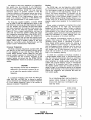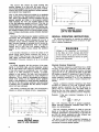
1
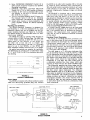
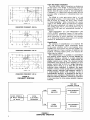
2 2 2 HARTREY AVE.. EVANSTON, IL. 6 0 2 0 4 u.S.A.
AREA CODE 3 1 2 / 8 6 6 - 2 2 0 0
TWX: 9 1 0 - 2 3 1 - 0 0 4 8
.
CABLE: SHUREMICRO
TELEX 72-4381
1
SHEET
DATA
MODEL SR106
AND SR106-2E
ELECTRONIC CROSSOVERS
OPERATION AND SERVICE MANUAL
Voltage Gain ..............0 2 1 dB (low or high frequency
output) with 47-kilohm output
termination
- 1.5
1 dB with 600-ohm
output termination
+
The Shure Model SR106 Electronic Crossover is a
selectable-frequency dividing network, designed for
use with two- or three-way speaker systems such as
the Shure SR108 Extended Range Speaker System in
high-quality sound systems. It utilizes the principle
of biamplification to separate an audio console or
mixer-preamplifier output into two frequency bands for
distribution to separate power amplifiers. In this manner, the advantages of low distortion, increased highfrequency power, wide dynamic range, and maximum
efficiency are obtained.
DESCRIPTION
The SR106 provides crossover frequencies of 500
Hz, 800 Hz and 2600 Hz. It can be used to provide two
output frequency bands or, in conjunction with a
second SR106, to provide three output frequency
bands, with each output routed to a separate power
amplifier (triamplification). The SR106 contains both
professional three-pin and phone jack input and output connectors, and can be operated in line level balanced and unbalanced systems.
The SR106 is designed for maximum simplicity of
operation and maintenance. A frequency-selector
switch and a power on-off switch are the only controls. Silicon transistors and other solid-state devices
are used throughout. All components are of the highest quality and are operated well within their respective ratings to assure maximum reliability under
normal use conditions.
The SR106 and SR106-2E are identical except that
the SR106 operates from 108-132 Vac, and the
SR106-2E operates from either 105-125 or 210-250 Vac
(switch-selectable).
All SR106 Series units are supplied with four rackmounting screws for mounting in 483 mm (standard 19
in.) audio equipment racks or in optional Shure A30A
or A105A Carrying Cases. In addition, the SR106 is
supplied with a protective power switch cover and the
SR106-2E is supplied with an ac line cord (without
power plug). The SR106 (only) is listed by Underwriters' Laboratories, Inc., and is listed by Canadian
Standards Association as certified.
Input Sensitivity ........1-volt input produces I-volt
output (unity gain) with
47-kilohm output termination
I-volt input produces 0.84-volt
output with 600-ohm output
termination
Frequency
Response
................ Electrical
sum of outputs (phase
reversed): flat t 2 dB,
20-20,000 HZ
High-frequency output: 12 dB/
octave rolloff below crossover
Low-frequency output: 6 dB/
octave rolloff above crossover
(see Figure E)
Phase ........................ ..Input and low frequency output
connectors in phase, high
frequency output reversed
phase
lnput Common
Mode Rejection ......92 dB minimum at 100 Hz
Input Impedance ........47 kilohms
Total Harmonic
Distortion ................1% max. (I-volt input; low
frequency: 20-2,600 Hz; high
frequency: 500-20,000 Hz)
Hum and Noise
.......... - 96
dBV max. low or high
frequency output (through
20,000 Hz noise-bandwidth
filter with 20 Hz lower cut-off;
600-ohm source, 47-kilohm
output terminations)
Noise ..........................- 98 dBV max. low or high
frequency output (through
20,000 Hz noise-bandwidth
filter with 300 Hz lower cut-off;
600-ohm source, 47-kilohm
output terminations)
Clipping Level ............
+ 18 dBm (6.2V) min. input from
30-20,000 Hz with 600-ohm or
greater output loads.
SPECIFICATIONS
Recommended Output
Load Impedance ....600 ohms minimum
(115 ohms actual output impedance)
Type ............................ All silicon transistor electronic
crossover network
Crossover
Frequency .............. 500 Hz, 800 Hz or 2600 Hz
(selectable)
Power Supply ............SR106: 120 volts t l o % , 50/60
Hz ac only. SR106-2E: 105-125
or 210-250 volts, 50/60 Hz ac
only. Power consumption:
3 watts maximum.
Copyright 1979, Shure Brothers
27A1145 (SF)
Inc.
Printed in U.5.A
I
FIGURE A.
SR106 FRONT PANEL
Temperature Range:
Operating ................ - 7" to 57°C (20" to 135°F)
Storage .............._ - 29" to 71 "C (-20" to 160°F)
8.
Dimensions ................ 44.5 mm height x 483 mm width
x 216 mm depth (1% in. x
19 in. x 8% in.)
9.
Weight ........................ 3 kg (6 Ib, 8.8 oz)
Finish .......................... Matte black
Installation .................. Equipped for standard 483 mm
(19 in.) audio rack mounting;
may be operated in optional
A30A or A105A Carrying Case
(with other equipment)
10.
Certifications
12.
.............. ~ i s t e dby
Underwriters' Laboratories, Inc.; listed by Canadian
Standards Association as certified (SR106 only)
11.
or 2600 Hz for separation of high- and lowfrequency signals to power amplifiers.
LlNE LEVEL INPUT 3-Pin Female ConnectorProvides balanced bridging, high-impedance input connection from audio console or mixerpreamplifier. May be unbalanced externally.
LlNE LEVEL INPUT Phone Jack-Provides
balanced or unbalanced bridging, high-impedance
input connection from audio console or mixerpreamplifier.
Ac Grounded Line Cord-Connects
unit to ac
power source (SR106 only).
AC (MAINS) POWER 3-Pin Connector-Connects unit to ac (mains) power source via
supplied line cord (SR106-2E only).
VOLTAGE SELECTOR Slide Switch-Selects
115V or 220V input power (SR106-2E only).
General Operating Instructions
OPERATING INSTRUCTIONS
WARNING
Functional Description (Refer to Figures A and B)
1. Power-On Indicator Lamp-Indicates ac power
is being applied to unit.
2. POWER ON-OFF Switch-Controls ac power to
unit.
3. LlNE LEVEL OUTPUTS/LOW FREQUENCY 3Pin Male Connector-Provides
low-frequency
balanced output connection to power amplifier.
May be unbalanced externally.
4. LlNE LEVEL OUTPUTS/LOW FREQUENCY
Phone Jack-Provides
low-frequency balanced
or unbalanced output connection to power amplifier.
5. LlNE LEVEL OUTPUTS/HIGH FREQUENCY
Phone Jack-Provides high-frequency balanced
or unbalanced output connection to power amplifier.
6. LlNE LEVEL OUTPUTS/HIGH FREQUENCY 3Pin Male Connector-Provides
high-frequency
balanced output connection to power amplifier.
May be unbalanced externally.
7. CROSSOVER FREQUENCY Slide SwitchSelects crossover frequency of 500 Hz, 800 Hz
MTIM
II
1. Using hardware provided, install SR106 securely
in 483 mm (standard 19 in.) rack or optional
A30A or A105A Carrying Case prior to making
electrical connections.
2. Connect SR106 LlNE LEVEL OUTPUT/LOW FREQUENCY 3-pin connector or phone jack (3, 4)
to (low frequency) power amplifier line level
input.
3. Connect SR106 LlNE LEVEL OUTPUT/HIGH
FREQUENCY &pin connector or phone jack
(5, 6) to second (high frequency) power amplifier
line level input.
4. Connect audio console or mixer-preamplifier line
level output to SR106 LlNE LEVEL INPUT &pin
connector or phone jack (8, 9).
5. Make sure speaker systems are properly connected to power amplifiers and are adjusted
for biamplified operation.
t
if(TOR
rr
To reduce the risk of fire or electric shock,
do not expose this appliance to rain or
extreme moisture.
rolula 3 whr
SR106-2E ONLY
\12
10
3
FIGURE B.
SR106 REAR PANEL
7
8
9
6. Move CROSSOVER FREQUENCY Switch (7) to
select proper crossover frequency (see Speaker
Operating Instructions).
7. (SR106-2E only) Move VOLTAGE SELECTOR
Switch (12) to 115V or 220V position as desired.
8. Connect ac line cord to grounded 108- to 132volt (SR106), or 105-125V or 210-250V (SR1062E), 50/60 Hz ac source.
9. Turn on front-panel POWER ON-OFF Switch (2).
Red indicator lamp (1) will go on, indicating
power application. The SR106 is now operating.
1@. Adjust audio console or mixer-preamplifier and
power amplifier controls for desired operating
levels.
Mounting and Ventilation
The SR106 Electronic Crossover is designed for
rack-mounting in a 483 mm (standard 19 in.) audio
equipment cabinet rack and is supplied with the necessary mounting hardware (see Figure C). If possible,
the SR106 should be rack-mounted below its associated power amplifiers.
The SR106 may also be operated while mounted in
a Shure A30A or A105A Carrying Case. The A30A has
a panel height capacity of 88.9 mm (3Y2 in.), providing space for two SRlOG's, or one SR106 and
one other unit of 44.5 mm (1% in.) height. The
A105A has a panel height of 178 mm (7 in.), providing
space for up to four SRlO6's, or one SR106 and
other equipment totaling 133.4 mm (5Y4 in.) in height.
No special precautions are required for ventilation.
The SR106 may be operated over a temperature range
of - 7" to 57°C (20" to 135°F) in continuous duty without derating.
483 mm
(19 1N!
-44
'NOT
4 mrn(1-3/4
IN,
lNCLUDlN6 CABLE/CONNECTOR CLEARANCE DEPTH
FIGURE C.
OVERALL DIMENSIONS
Power Supply
The SR106 is furnished with a three-conductor power
cable and three-prong grounded plug (10). Connect
LlNE LEVEL INPUT
the SR106 to an outlet which supplies 108 to 132 volts
ac, 50/60 Hz power. Maximum power consumption at
120 volts under normal operating conditions is 3 watts
(0.025 amperes at 120 volts). If extension cords are
required, a high-quality, 18-gauge or larger cord should
be used.
The SR106-2E is furnished with a three-conductor
line cord without a power plug. Obtain a suitable 3-pin
male power plug and attach it to the line cord. The
plug should be installed by qualified service personnel.
(Brown lead goes to "hot" or "live" terminal, blue lead
to neutral terminal, and greenfyellow lead to ground
or earth terminal.) Select proper operating voltage
(115V for 105-125V supply or 220V for 210-250V supply)
using the VOLTAGE SELECTOR Switch (12).
A POWER ON-OFF toggle switch on the front panel
(2) controls the application of ac power to the SR106,
and a red indicator lamp (1) indicates the power-on
condition. The tamper-proof cover supplied (SR106
only) may be used to eliminate accidental movement
of this switch.
Functional Circuit Description
The inputs of the SR106 Electronic Crossover consist of one phone jack (9) and one three-pin female
audio connector (8) (see Figure D). The phone jack is
a three-circuit (stereo) type and is wired in parallel
with the three-pin connector to provide a balanced input with either connector. The input signal then passes
through a 6 dB stepdown input isolation transformer
to a unity-gain buffer amplifier.
The next stage is a 12 dB/octave high-pass filter
with an operating frequency of 500 Hz, 800 Hz or 2600
Hz. All frequencies above the selectable operating frequency are routed to a unity-gain filter amplifier stage.
One output of this stage goes to a 6 dB gain, 600-ohm
line driver, which drives the high-frequency output
transformer to + I 8 dBm. The other output goes to
a differential amplifier/line driver stage, which also
receives an input from the first buffer amplifier stage.
The differential amplifier/line driver stage thus derives the low-pass signal by responding to the difference between the buffer amplifier signal (all-pass) and
the filter circuit signal (high-pass). The difference
signal ampli.tude rolls off at 6 dB/octave. The difference signal is amplified and drives the low-frequency
output transformer. The resulting frequency response
curves are shown in Figure E. Adding the two outputs
out-of-phase provides a flat output response from 20
to 20,000 Hz. High- and low-frequency outputs appear
on both phone jacks and three-pin, professional, male
audio connectors.
HIGH-PASS FILTER
-------- --- - - -- - -1
HIGH FREQUENCY
LEVEL OUTPUTS
LINE
LOW FREQUENCY
LlNE LEVEL OUTPUTS
FIGURE D.
BLOCK DIAGRAM
Input and Output Connections
Two LlNE LEVEL INPUT Connectors are located on
the rear panel of the SR106. A professional, three-pin
female audio connector (8) provides a balanced connection from the audio console or mixer-preamplifier.
A standard 1/4 in. three-circuit (stereo) phone jack (9)
provides either a balanced or unbalanced input connection.
The SR106 is a unity gain device, that is, a 1-volt
input signal provides a 1-volt output signal. The SR106
may be driven by virtually any mixer, audio console
or mixer-preamplifier. When connecting the source
output to the SR106, follow the instructions supplied
with the source equipment with regard to connectors
and cabling. Note that if a two-circuit phone plug is
used, the SR106 input will automatically become unbalanced.
HlGH FREQUENCY and LOW FREQUENCY LlNE
LEVEL OUTPUT connectors consist of both professional, three-pin, male audio connectors (3, 6) for balanced connection to power amplifiers, and standard
1/4 in. three-circuit (stereo) phone jacks (4, 5) provide
balanced or unbalanced connections.
+ 10
m
P
0
w
0
B
-10
W
W
:- 2 0
w
-30
20
50
100
200
400 600
FREQUENCY
1K
2K
4K
IOK
6K
2OK
(HZ )
CROSSOVER FREQUENCY: 2600 Hz
Biamplification
The principle of biamplification is to separate the
high- and low-frequency signal components ahead
of the power amplifier, and to use separate power
amplifiers for each section of a two-way speaker system (see Figure F). Proper matching of amplifiers and
speakers, increased system power, and reduced distortion may be realized.
With biamplification it is possible to power-match
each speaker system section to a power amplifier for
maximum efficiency, whereas if a single equivalent
high-power amplifier were used it would exceed the
speaker system power rating. The improved system
performance using separate power amplifiers for each
speaker section may be that of a single high-power
amplifier whose rating is up to twice the sum of the
individual power amplifiers. In addition, the power
amplifier overload caused by high-level, low-frequency
signals severely degrades high-frequency signals in
a single-amplifier system. This overload, a form of
intermodulation distortion, is eliminated by the use of
separate power amplifiers. Biamplification also eliminates low-frequency distortion produced by saturation
of iron cores used in some passive speaker crossover
networks.
CROSSOVER FREQUENCY: 800 Hz
+I0
m
a
0
I
0
-10
Y
",
5 -20
W
-30
20
50
100
200
400 600
1K
2K
4K
6K
IOK
20K
CROSSOVER FREQUENCY: 500 Hz
FIGURE E.
FREQUENCY RESPONSE
TWO-WAY
SPEAKER SYSTEM
r------POWER
AMPLIFIER
HIGH
H
AUDIO CONSOLE
OR MIXER-PREAMP
OR MIXER
i
I
I -
HIGH-FREQUENCY
SPEAKERS
1
I
I
I
SR106
ELECTRONIC
CROSSOVER
LOW
-
POWER
AMPLIFIER
FIGURE F.
BlAMPLlFlED OPERATION
II
I
I
LOW-FREQUENCY
SPEAKERS
I
I
I
The outputs of the power amplifiers in a biamplification system may be connected to any high-power,
two-way speaker system with separate driver connections such as the Shure SR108. The only important
restriction placed on speaker systems is that the
crossover frequency of the speaker system must match
the crossover frequency selected on the back of the
SR106. Damage to the high-frequency drivers may
result if the crossover frequency of the SR106 is set
below that recommended for the speaker system.
For three-way speaker systems, a second SR106
may be used to split the high-frequency output of the
first SR106 into mid-range and high-frequency outputs.
The two SRlO6's thus separate the line level signal
into three components for routing to three power amplifiers and into the three-way speaker system (see
Figure G). This is called triamplification, and may be
used with any three-way speaker system with crossover frequencies matching those of the SR106. NOTE:
Certain three-way speaker systems are designed for
biamplified operation only, and use their internal crossover networks to separate the mid- and high-frequency
signals. When using a speaker system of this type,
follow the instructions under Biamplification and the
speaker system manufacturer's instructions.
Crossover Frequencies
The three crossover frequencies available (500, 800
and 2600 Hz) on the SR106 rear-panel selector switch
(7) are designed for use with the Shure SR108 Extended Range Speaker System (2600 Hz) and other
popular speaker systems. In connecting the SR106,
it is imperative that the crossover frequency of the
speaker system be known and the SR106 CROSSOVER FREQUENCY Switch be set before operating the
system.
CAUTION
High-frequency drivers may be damaged or
destroyed if the electronic crossover is not
set to match the speaker system crossover
frequency.
Phasing
The SR106 high- and low-frequency output signals
are intentionally wired out of phase (opposite polarity).
The low-frequency output is in phase with the input,
and the phase of the high-frequency output is reversed. This phase relationship is consistent with the
requirements of the passive 12 dB/octave crossover
networks used in most popular speaker systems. The
Shure SR108 Extended Range Speaker System is internally wired out of phase and provides the correct
acoustic output when operated in the biamplification
mode.
Proper wiring is necessary to maintain the correct
phase relationship of the high- and low-frequency
speakers in the crossover region. Failure to maintain
proper phasing may cause incorrect overall response
characteristics in the critical mid-range frequencies.
The speaker system instruction manual should be consulted for information on proper phasing when connecting the speakers to the power amplifiers.
The following considerations should be given to
phasing: When using the SR106 and identical power
amplifiers (Shure SR105 or equivalent) to power a
Shure Model SR108 Speaker System, the phasing is
correct. Different speaker systems or dissimilar highand low-frequency power amplifiers may be used as
long as all low-frequency sections are in phase with
one another and all high-frequency sections are in
phase with one another, as well as maintaining proper
high- to low-frequency phasing.
To check for a possible out-of-phase condition in
a single speaker system (high- to low-frequency phasing), the following listening test should be performed.
Connect the SR106, program input equipment, and
power amplifiers to a single speaker system. Feed the
system with program material (vocal or instrumental)
and adjust for a moderate level. Listen carefully to
the speaker system output and reverse the phase of
either the high- or low-frequency section of the speaker
system while listening to the same program material.
Choose the connection that produces the most uniform sound quality.
If a crossover frequency other than the three provided (500, 800, and 2600 Hz) is desired a qualified
service technician can change the crossover frequency
to a new desired frequency. Refer to the section on
Alternate Crossover Frequencies.
CAUTION
Do not interchange high- and low-frequency
speaker cables. Damage to high-frequency
drivers from high level, low-frequency signals may result.
SPEAKER SYSTEM
-
H
AUDIO CONSOLE
OR MIXER-PREAMPOR MIXER
-
SR106
CROSSOVER
( 5 0 0 HZ)
E
SRlO6
ELECTRONIC
CROSSOVER
( 2 6 0 0 HZ)
-
-
HIGH
MID
(LOW)
-
LOW
POWER
AMPLIFIER
POWER
AMPLIFIER
POWER
AMPLIFIER
r-------
I
I
I
I
I
I
I
I
I
I
,
HIGH-FREQUENCY
SPEAKERS
MID-FREQUENCY
SPEAKERS
7
I
I
I
I
I
I
I
LOW-FREQUENCY
SPEAKERS
I
I
I
L-------J
FIGURE G.
TRlAMPLIFIED OPERATION
The second test should be made feeding two
speaker systems at a time with the same vocal or
instrumental program material or noise (pink or white).
Connect the SR106, power amplifiers, speaker systems,
and program input equipment.
Turn on the sound system and adjust for a moderate
level. Disconnect the high-frequency driver input cables. Stand approximately mid-way between the two
speaker systems and listen to the program material
while reversing the "hot" and common leads to one
of the low-frequency speaker sections. (This may be
accomplished by wire-reversing or by a simple crosswired, double-pole, double-throw switch.) Use the connection that gives a localized sound, centered between
the speaker systems; this is the correct phase connection. A diffuse, directionless sound indicates improper
phasing.
Reconnect the high-frequency speaker sections and
disconnect the low-frequency sections. Perform the
same test as above. Correct phasing will provide a
localized sound, centered between the speaker system; incorrect phasing is indicated by the sound appearing to come predominantly from one speaker
system, and to shift from one speaker system to
another as the listener moves around the audience
area.
If it becomes necessary to invert the phase of the
SR106 output signal without changing any wiring, a
Shure A15PR Phase Reverser may be inserted in the
LINE LEVEL OUTPUTS/HIGH FREQUENCY or /LOW
FREQUENCY three-pin connector (6, 3) of the SR106.
Shelving
In normal operation the flat portions of the passbands of the SR106 high- and low-frequency outputs
are at equal levels (see Figure E). However, because
of the wide variance in acoustically "live" and "dead"
rooms, it is often necessary to "shelve," or adjust,
relative to one another, the high- and low-frequency
signals in order to compensate for room reflection or
absorption. This is done by decreasing the volume or
output level setting on the desired power amplifier
(high- or low-frequency) to some arbitrary position below that of the other power amplifier, and performing
a listening test to establish that the desired compensation has been achieved.
The effects of shelving the high- and low-frequency
outputs are shown in Figures H and J, respectively.
+ 10
-
m
W
p
0
W
W
z
-I0 2 0
50
100
200
400 600
IK
2K
4K
6K
IOK
2OK
FREWNCY (HZ)
FIGURE J.
TYPICAL SHELVING EFFECT:
LOW TO HlGH FREQUENCY
SPECIAL OPERATING INSTRUCTIONS
The following information is supplied to enable the
user to utilize the SR106 Electronic Crossover in special or custom installations.
WARNING
Voltages in this equipment are hazardous
to life. Make all circuit changes described
in this section with ac power disconnected.
Circuit changes should be referred to qualified service personnel.
Alternate Crossover Frequencies
The crossover frequency is determined by a single
two-pole, 12 dB/octave, high-pass, active filter. Transsistors Q3 and Q4 and associated circuitry, including
capacitors C4 to C13, comprise this filter. In the 2600
HZ position of switch S1 capacitors C4 and C13 determine the crossover frequency. In the 800 and 500 HZ
switch positions capacitors C5 to C12 are selectively
added in parallel to produce a lower crossover frequency.
Should a different crossover frequency than those
provided be desired for use with a special custom
speaker system, capacitors C4 and C13 may be replaced. The two capacitors have the same value; to
determine the new value capacitor required in microfarads, divide 7.02 by the desired crossover frequency.
Example:
+I0
If the new crossover frequency is to be
1500 Hz,
m
0
+
U.
g
Use
5% tolerance, 50-volt or greater capacitors.
Stable film-type capacitors, matched within 10% or
better, are recommended.
0
W
Y
L?
z
W
- 10
20
50
100
200
400 600
FREWENCY
IK
2K
4K
[HZ)
FIGURE H.
TYPICAL SHELVING EFFECT:
HlGH TO LOW FREQUENCY
6K
IOK
ZOK
The new crossover frequency is 1500 Hz with the
switch in the 2600 HZ switch position. Note that the
crossover frequencies corresponding to the 500 HZ
and 800 HZ switch positions are also different due
to the change in capacitors C4 and C13.
Be sure to note the new crossover frequency on
the switch position to avoid damage due to accidental
connection to another speaker system.
Adding Level Controls
If the power amplifiers in use do not have volume
controls, or if volume controls are desired at the
SR106 location, external controls may be added to
the SR106 outputs. Obtain two 1,000-ohm linear taper
potentiometers (Allen-Bradley Type J or equivalent)
and mount them in a 44.5 mm (1% in.) rack panel. Wire
the potentiometers to the SR106 output as shown in
Figure K.
WARNING
Voltages in this equipment are hazardous
to life. Refer servicing to qualified service
personnel.
Replacement Parts
Parts that are readily available through local electronic parts distributors are not shown on the accompanying Parts List. Their values are shown on the
Circuit Diagram (Figure P). Commercial parts not
readily available and unique parts are shown on the
Parts List and may be ordered directly from the factory.
For shelving adjustments, set the controls to maximum volume position (full clockwise) and reduce one
control for the desired effect.
FROM SR106
OUTPUT
TO POWER AMPLIFIER
INPUT
T
-
ONE-HALF
The commercial alternates shown on the Parts List
are not necessarily equivalents, but are electrically and
mechanically similar, and may be used in the event
that direct factory replacements are not immediately
available. To maintain the highest possible performance and reliability, Shure factory replacement parts
should be used. When ordering replacement parts,
specify the Shure Replacement Kit Number, description, product model number and serial number.
OF CIRCUIT SHOWN
FIGURE K.
LEVEL CONTROL WIRING
Telephone Line Surge Protection
When using the SR106 to feed a telephone line subject to lightning-induced voltage surges, the following
part (commercially available) can be installed across
the LINE LEVEL OUTPUTSIHIGH FREQUENCY and
/LOW FREQUENCY three-pin jacks (6, 3) or phone
jacks (5, 4) to provide additional protection for output
circuit components: Thyrector, General Electric Co.,
Part number 6RS20SPl B1.
Cover Removal
To service components inside the chassis, the protective top cover must be removed. This is done by
removing 10 screws from the top surface and lifting
the cover off.
Printed Circuit Board Removal
The SR106 chassis contains a printed circuit board
assembly. The foil side of the board may be made accessible for servicing, without disconnecting any leads,
by removing the four Phillips head screws securing
the board. The board may be completely removed as
follows (see Figure L). Remove all 14 interconnecting
leads from the push-on board terminals, noting connections as listed in the table below.
SERVICE INSTRUCTIONS
Service (See Guarantee)
The SR106 Electronic Crossover uses components
of the highest quality, operating well within their respective ratings to assure long life.
T2
AI
CII
T3
CIO
T4
TI
D2
C6
J5
J6
C5
RI
J3
SI
FIGURE L.
SR106 TOP VIEW, COVER REMOVED
CI
C2
CAUTION
Similar wire colors are used in different circuits; make sure proper re-connections can
be made. Take care not to bend or break
the push-on terminals.
CIRCUIT BOARD WIRE COLORS
Letter
Wire Color
Letter
Wire Color
To check transistors, the ohmmeter should be set
to the 100- or 1,000-ohm scale. Transistors and diodes
must be removed from the circuit before testing. If
all conditions in the following table are met, the transistor may be considered free of any major defect; if
any of the following conditions are not met, the transistor should be replaced. See Notes to Circuit Diagram (Figure N) for transistor lead codes.
Ohmmeter Connections
Ohmmeter Reading
A
Red
H
Red
"Plus" Lead "Minus" Lead
NPN
Transistor
PNP
Transistor
B
Black
J
Red
Collector
Emitter
High
High
C
Purple
K
Blue
Emitter
Collector
High
High
D
Yellow/Purple
L
Red
Collector
Base
High
Low
E
Yellow/Black
M
Blue
Emitter
Base
F
Yellow/Red
N
Black
Base
Collector
Low
G
Black
P
White
Base
Emitter
Low
NOTE: Production variations may result in wire colors differing from those in the table.
Remove the four Phillips head screws from the board
and remove the board from the chassis.
Replace cover after servicing board.
Transistor and Diode Removal
All transistors and diodes used in the SR106 are mechanically supported by their leads. When replacing
these devices, proper lead configurations must be
followed. Minimum soldering heat (preferably with a
low-wattage soldering iron) should be used to avoid
damage to the device. Transistor lead codes are included in the Notes to Circuit Diagram (Figure N).
Transistor and Diode Checking
Defective transistors and diodes may be located by
use of a standard ohmmeter such as a Simpson 260.
Polarity of the ohmmeter must be verified before
these checks are made.
With a known diode orientation, measure the diode
resistance in the forward and reverse directions. The
lowest meter reading will establish the probe at the
cathode end (schematic symbol arrow points to cathode) as the "minus" probe while the other probe
will be "plus." Some ohmmeters are not polarized in
this manner with relation to "volts plus probe" and
"volts minus probe." With the ohmmeter "plus" probe
on the anode end of a diode, and the "minus" probe
on the cathode end, the ohmmeter should read approximately 2000 ohms or less. With the meter probes
reversed, a reading of about 10,000 ohms or more
should be obtained. If either of these conditions is
not met, the diode should be replaced.
Low
High
*Not a significant measurement.
Replacement Parts List
The commercial alternates shown in the following
parts list are not necessarily equivalent parts, but are
electrically and mechanically similar, and may be
used if direct factory replacements are not immediately available. To maintain highest possible performance and reliability, Shure Factory Replacement
Parts should be used.
Service Illustrations
The pages that follow contain a Parts Location
Drawing for the printed circuit board (Figure M) and
an overall Circuit Diagram (Figure P). Foil circuit paths
are shown as shaded areas in Figure M. The Circuit
Diagram shows all printed circuit board and chassismounted parts.
GUARANTEE
This Shure product is guaranteed in normal use to
be free from electrical and mechanical defects for a
period of one year from date of purchase. Please
retain proof of purchase date. This guarantee includes
all parts and labor. This guarantee is in lieu of any
and all other guarantees or warranties, express or
implied, and there shall be no recovery for any consequential or incidental damages.
SHIPPING INSTRUCTIONS
Carefully repack the unit and return it prepaid to:
Shure Brothers Incorporated
Attention: Service Department
1501 West Shure Drive
Arlington Heights, Illinois 60004
If outside the United States, return the unit to your
dealer or Authorized Shure Service Center for repair.
The unit will be returned to you prepaid.
REPLACEMENT PARTS LIST (See Figures L and P)
I
Reference
Designation
I
I
Replacement Kit Consists Of:
Replacement
Kit No.*
Qty.
Part No.
Commercial
Alternate
Description
CHASSIS-MOUNTED PARTS AND ASSEMBLIES
A1
-
90A2058
Printed Circuit Board Assembly
None
C10
-
-
86L628
Capacitor, Electrolytic,
250 ,F, 40V
CDE BR250-50
C11
-
-
86B632
Capacitor, Electrolytic,
1000 F
, , 40V
None
4
86A404
Silicon Rectifier, 100V,
-
80A297
Fuse, SLO-BLO, 1/16A, 250V,
Pigtail (SR106-2E)
Littelfuse 315.062
2
95A482
Connector, Female, 3-Pin
Audio, LlNE LEVEL INPUT
Switchcraft C3F
-
95D446
Connector, Phone Jack,
3-Conductor, Open Circuit,
LlNE LEVEL INPUT and LOW
and HlGH LEVEL OUTPUT
Switchcraft 12B
1
95A198
Connector, Male, 3-Pin
Audio, LOW and HlGH LEVEL
OUTPUT
Switchcraft C3M
D l , D2
F1
J1
J2, J4, J6
J3, J5
RKC21
-
RKC83
-
RK122P
Y2 A
Motorola 1N4002
J7
-
-
95A689
Connector, 3-Pin,
AC (MAINS) POWER (SR106-2E)
None
L1-L4
-
-
80A250
Ferrite Bead Ring
Stackpole 57-0181;
Ferronics 21-0351J
MP1
-
-
39A418
Nameplate, Front-Panel
None
31A1144A
Cover, Switch, POWER (SR106)
None
1
80A79
Lamp, Indicator
Leecraft 36N1311-6
-
55A105
Switch, Slide, 4P3T
None
S2
-
-
55A96
Switch, Toggle, SPST,
POWER ON-OFF (SR106)
Cutler-Hammer
7501K13
S2
-
-
55A117
Switch, Toggle, SPST,
POWER ON-OFF (SR106-2E)
None
S3
-
-
55A116
Switch, Slide, DPDT,
VOLTAGE SELECTOR
(SR106-2E)
None
T1
-
-
90C2150
Transformer and Shield
Assembly, Line Level Input
None
T2, T3
-
-
518229
Transformer, Low and High
Frequency Line Level Output
None
T4
-
51A253
Transformer, Power (SR106)
None
T4
-
51A259
Transformer, Power (SR106-2E)
None
W1
-
-
95A632
Line Cord and 3-Conductor
Ac Plug Assembly (SR106)
Belden 17408
-
90A1888
Line Cord and 3-Conductor
Ac Plug Assembly (SR106-2E)
None
MP2
PL1
S1
W1
RKC45
*Parts listed as RKC Kits should be ordered by that number.
Any orders received for piece parts where RKC Kit number is shown will be shipped in RKC quantities.
"Sprague Type 225P has a +lo% tolerance; select to &5% if possible.
REPLACEMENT PARTS LIST-Continued
Reference
Designation
Replacement Kit Consists Of:
Replacement
Kit No.*
Part No.
Qty.
Commercial
Alternate
Description
CIRCUIT BOARD ASSEMBLY (Al)
Q2, Q 4 0 6
Q10
Q8, Q12
I
-
RKC66
1 1
-
I
1
1
86~348
86A335
1
1
Capacitor, Electrolytic,
4.7 ,F, 35v
Sprague 30D-TE1303;
CDE NLW-5-50
Capacitor, Electrolytic,
250 p.F, 40V
CDE BR250-50
Capacitor, Film,
.0027 ,F, 1OOV & 5%
Sprague 225P27291* *
Capacitor, Film,
.0022 ,F, lOOV t 5%
Sprague 225P22291**
Capacitor, Film,
.0039 ,F, 10OV zk 5%
Sprague 225P39291*'
Capacitor, Film,
.0015 ,F, 100V t 10%
Sprague 225P15291
Capacitor, Film,
.O1 ,F, lOOV t 5%
Sprague 225P10391" "
Silicon Rectifier, 50V, YzA
Motorola 1N4001
Transistor, Silicon, Low
Power, NPN
Motorola 2N5210
Transistor, Silicon, Low
Power, PNP
Motorola or
Fairchild 2N5087
Transistor, Silicon, PNP
*Parts listed as RKC Kits should be ordered by that number.
Any orders received for piece parts where RKC Kit number is shown will be shipped in RKC quantities
"Sprague Type 225P has a 210% tolerance; select to 2 5 % if possible.
FIGURE M.
PRINTED CIRCUIT BOARD PARTS LOCATION
NOTES TO CIRCUIT DIAGRAM
General
Shure part numbers are not shown in the Parts List
accompanying the Circuit Diagram (Figure P) if parts
are readily available through local electronics parts
suppliers. In these instances, the Circuit Diagram
shows only the reference designation and value of
the standard parts.
All capacitor values are shown in microfarads unless otherwise designated. All non-electrolytic capacitors are 100 working volts dc or more unless otherwise specified. The capacitor tolerance is shown for
the crossover-frequency-determining capacitors C4 to
C13. Electrolytic capacitors are shown in microfarads
X volts.
All resistor values are shown in ohms (k=1000).
Resistors are %-watt 10% tolerance unless otherwise
specified.
Transistor lead codes are shown in Figure N. Acceptable replacements are shown in the Parts List.
The following ground symbols denote:
*l
Chassis Ground
Circuit Ground
Printed Circuit Board Ground
Troubleshooting
A general troubleshooting process is as follows: If
the SR106 is completely "dead," check the ac power
source and power slipply output (36V at pin H of
printed circuit board). If the output is distorted, low
or not present, apply an input signal as described
under Ac Voltage Measurements below, and determine
that the input voltage to the board assembly is correct.
If an incorrect ac voltage is found on the board, perform Dc Voltage Measurements as described below to
isolate the problem area.
AC Voltage Measurements
on
The numbers within rectangular symbols
the Circuit Diagram denote the ac voltage at that
point under the following test conditions:
1. Voltage measured with respect to chassis unless otherwise indicated.
0
2. Line voltage: 120V, 50/60 Hz (SR106), or 115V
or 220V (SR106-2E).
3. Test signal of l.OV, 200 Hz (low-frequency) or
5 kHz (high-frequency) applied across connector
J1 through 600 ohms.
4. Measurements made with ac VTVM of 1 megohm
or greater input impedance.
5. Loads across LlNE LEVEL OUTPUTS Connectors
J3 and J5: 47 kilohms.
6. Ac voltage measurements may vary t 30% from
values shown.
DC Voltage Measurements
The numbers within elliptical symbols o on the
Circuit Diagram denote the dc voltage at that point
under the following test conditions:
1. Voltages measured with respect to chassis unless otherwise indicated.
2. Line voltage: 120V, 50/60 Hz (SR106), or 115V
or 220V (SR106-2E).
3. No input signal applied.
4. Dc voltage measurements may vary t 20% from
values shown.
5. Measurements made with VTVM of 11 megohms
or greater input impedance.
Resistance Measurements
With the ac line cord disconnected from the ac
source and the POWER ON-OFF Switch in the OFF
position, the following ohmmeter measurements may
be made:
1. Transformers may be checked for continuity of
each winding.
2. To test transistors and diodes, see Transistor
and Diode Checking.
.@
E
01 03
05 p9
.@
1-
pK77q
.a .Q.a(J.6
E
E
07.011
E
E
E
02,P4
E
Q8,012
as, a,o
FIGURE N.
TRANSISTOR LEAD CODES
ARCHITECTS' AND ENGINEERS' SPECIFICATIONS *
The Electronic Crossover shall be a rack-mounted
120-volt, 50160 Hz line-operated, all silicon transistor,
active crossover network for separating the output
signals from an audio console or mixer-preamplifier
into high- and low-frequency signals for routing to
separate power amplifiers and two-way speaker sys"
tems.
The Electronic Crossover shall be a unity voltage
gain amplifier for either high- or low-frequency output
signals, with a flat f 2 dB frequency response over
the range of 20 to
Hz when the high- Or lowfrequency output signals are added electrically out-ofphase. Input impedance shall be 150 kilohms 2 30%,
and recommended output load impedance shall be
600 ohms (termination for 1.5 dB loss) or 47 kilohms
(bridging for unity gain). The Electronic Crossover
shall evidence no visible clipping at either output from
30 to 20,000 Hz with a 15.8 dBV (6.2V) input level.
When terminated with a 600-ohm input resistance and
47-kilohm output loads, both high- and low-frequency
output signals shall have a maximum hum and noise
level of -96 dBV through a 20,000 Hz noise-bandwidth
207000
* All spec~ftcat~ons
apply to SR106-2E except operattng voltage
1 2 5 ~or 210-250~.
IS
105-
filter with a 20 Hz lower cut-off, and a maximum noise
level of -98 dBV through a 20,000 Hz noise-bandwidth
filter with a 300 Hz lower cut-off.
The Electronic Crossover shall have a POWER ONOFF Switch and a three-position CROSSOVER FREQUENCY Switch to select crossover frequencies of
500, 800 or 2600 Hz.
The Electronic Crossover shall be enclosed in a
metal, rack-mounting enclosure housing with a scuffresistant vinyl-covered front panel. The dimensions
shall be 44.5 mm (1% in.) in height, 483 mm (19 in.)
in width, and 216 mm (8V2 in.) in depth. The weight
shall be no more than kg (6 Ib, 8.8 oz).
The LINE LEVEL INPUT connectors shall be paralleled
female professional audio and three-circuit
%-inch phone jack connectors. The HIGH and LOW
FREQUENCY LINE LEVEL OUTPUT connectors shall
each be paralleled %pin male professional audio and
three-circuit phone jack connectors.
Any Electronic Crossover not meeting all of the
above specifications shall be deemed unacceptable
under this specification' The Electronic
Crossover
be a Shure Model SR106.
11
SR106-2E POWER SUPPLY