1
Harley-Davidson®
Screamin’ Eagle Pro Super Tuner
User’s Manual
Table of Contents
Section 1 – Introduction..................................................................................................................4
Kit Contents ...................................................................................................................................4
Disclaimer and Warnings ...............................................................................................................4
How to Use This Manual................................................................................................................5
Section 2 – Introduction to Harley-Davidson EFI Systems..........................................................6
How It Works .................................................................................................................................6
Harley-Davidson Electronic Sequential Port Fuel Injection System (ESPFI)..............................6
Current ESPFI Components.......................................................................................................6
Overview of How the Harley-Davidson ESPFI Functions...............................................................8
ESPFI System Operation...............................................................................................................9
Heat Management System.......................................................................................................10
Model Year 2007: .................................................................................................................10
Closed-Loop Operation................................................................................................................11
Background ..............................................................................................................................11
Tuning with Closed-Loop..........................................................................................................11
Section 3 – Software Installation .................................................................................................12
Installation of Screamin' Eagle Pro Super Tuner Software.......................................................12
Section 4 – Basic Overview of Super Tuner Software ...............................................................13
Section 5 – Basic and Advanced Tuning.....................................................................................15
Basic Tuning ................................................................................................................................15
Advanced Tuning .........................................................................................................................16
Section 6 – Toolbox ......................................................................................................................18
Data Items ...................................................................................................................................18
Quarter Mile and Speed/Distance Calculators .........................................................................20
Record VCI Data..........................................................................................................................20
Diagnostic Trouble Code (DTC) Display ......................................................................................20
System Information ......................................................................................................................20
Section 7 – Race Tuning Guide....................................................................................................21
Introduction to Race Tuning.........................................................................................................21
What Can the Screamin' Eagle Pro Super Tuner Do for Me? ..................................................21
What Can This Race Tuning Guide Do for Me? .......................................................................21
The Three Tuning Environments of the Race Tuning Guide ....................................................22
The Two Basic Performance Tests.......................................................................................22
Consistencies and Concerns in Testing.......................................................................................23
Checklist of Consistency Concerns ..........................................................................................24
Explaining Air-Fuel Ratio..........................................................................................................24
Why Would I Want to Adjust the AFR? .................................................................................25
Symptoms of a Rich or Lean AFR ........................................................................................25
Basic Tuning By Feel on Closed-Course Track ...........................................................................26
Overview - Tuning By Feel .......................................................................................................26
Where do I start?......................................................................................................................26
Inspect and Prepare Bike for Testing....................................................................................26
Test Bike to Determine if There Is a Need for a Tuning Adjustment ........................................27
Why would I want to adjust the AFR?.......................................................................................28
How would I adjust the AFR? ...................................................................................................29
Why Would I Want to Adjust the Spark Timing?.......................................................................30
How Would I Adjust Spark Timing? ..........................................................................................30
2
What Do I Do if the Starting, Idle or Warm-up Performance Needs Adjustment? ....................31
Advanced Tuning and Data Items on Closed-Course Track ........................................................32
Overview - Tuning With Data Items and Advanced Tuning ......................................................32
Where do I start?......................................................................................................................32
Inspect and Prepare Bike for Testing .......................................................................................33
Test Bike to Determine if There Is a Need for a Tuning Adjustment ........................................34
If Undesirable Symptoms Were Noted, Record ECM Engine Data Using Data Items ..........35
Why Would I Want to Adjust the AFR?.....................................................................................35
Using Knock Retard as an Indicator of Lean AFR....................................................................35
How Would I Adjust the AFR with Advanced Tuning?..............................................................36
Why Would I Want to Adjust the Spark Timing?.......................................................................37
How Would I Adjust Spark Timing with Advanced Tuning?......................................................37
Advanced Tuning, Chassis Dynamometer and AFR Meter..........................................................38
Overview - Tuning With a Chassis Dyno, AFR Meter and Advanced Tuning ...........................38
Where do I start?......................................................................................................................39
Inspect and Prepare Bike for Testing .......................................................................................39
Dyno-Test Bike to Determine if There is a Need for a Tuning Adjustment ...............................40
Why Would I Want to Adjust the AFR?.....................................................................................41
How Would I Adjust AFR with Advanced Tuning, Dyno and AFR Meter? ................................41
Why Would I Want to Adjust the Spark Timing?.......................................................................43
How Would I Adjust Spark Timing with Advanced Tuning?......................................................43
Miscellaneous Tuning ..................................................................................................................44
Cranking Fuel .......................................................................................................................44
Warmup Enrichment .............................................................................................................44
Idle RPM...............................................................................................................................44
IAC Warmup Steps ...............................................................................................................45
Acceleration Enrichment.......................................................................................................45
Deceleration Enleanment .....................................................................................................46
Section 8 – Frequently Asked Questions (FAQs) .......................................................................47
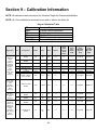
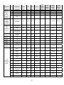
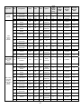
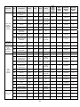
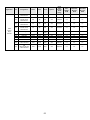
Section 9 – Calibration Information .............................................................................................49
Key to Calibration Table .......................................................................................................49
List of Screamin’ Eagle Accessories by Calibration .................................................................54
Section 10 – Glossary ...................................................................................................................65
3
Section 1 – Introduction
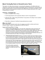
The Screamin' Eagle Pro Super Tuner Kit will provide the experienced race tuner with tools and data
similar to what Screamin' Eagle uses to create its EFI calibrations for Stage Kit configurations. The
system is designed for Harley-Davidson Electronic Sequential Port Fuel Injection, (ESPFI) systems
offered on the following EFI-Equipped models (from here on referred to as the “current ESPFI”
system):
• 2001 - later Softail,
• 2002 - later Touring,
• 2004 - later Dyna,
• 2002 - later V-Rod.
Kit Contents
•
•
1-CD containing:
o Screamin’ Eagle Pro Super Tuner Software
o Screamin' Eagle EFI calibrations (up to the time of this printing) for EFI-Equipped
models mentioned above.
o Electronic Screamin’ Eagle Pro Super Tuner User’s Manual
Vehicle Communication Interface (VCI)
NOTE: The VCI supplied with this software is for use on a single vehicle only. When the VCI is first
used to program a vehicle, it will be permanently locked to that vehicle, and cannot be used on any
other vehicle for programming.
This product is designed for Race
Use Only
Disclaimer and Warnings
Do not install the modified calibrations on any model other than those specified in this User’s Manual.
Doing so may result in poor engine performance, electrical-system damage, and/or engine damage.
This Screamin' Eagle Pro Super Tuner system is intended for high-performance applications only.
This engine-related performance part is not legal for use on pollution-controlled motor vehicles. Use
of this Screamin' Eagle Pro Super Tuner system may reduce or void the Limited Warranty Coverage.
This Screamin' Eagle Pro Super Tuner system allows the engine to reach optimum RPM. It is
extremely important that the rider use the tachometer to avoid harmful RPMs and possible engine
damage. Engine-related Performance Parts are intended for the experienced rider only.
Do not exceed 6200 RPM on all Twin Cam 88 engines that use stock valve springs. Exceeding 6200
RPM on these vehicles may cause engine damage.
Do not exceed 6200 RPM on balanced Twin Cam B 88 engines, regardless of additional engine
modifications. Exceeding 6200 RPM on these vehicles may cause engine damage.
4
How to Use This Manual
First – Read the “Introduction to Harley-Davidson EFI Systems”
While it may be tempting to bypass instructions in favor of immediately using the Screamin' Eagle Pro
Super Tuner, it is likely that some of the information in the Introduction will be critical to your
successful use of this product. Read the Introduction to gain a foundation of knowledge in how the
EFI system functions.
Second – Glance Through the User’s Manual
Take a few minutes to glance through all pages of this User’s Manual to get familiar with its contents.
Third – Get Comfortable With the Super Tuner Software
Open and view the Super Tuner software. Closely review the Super Tuner online help for specific
information about using the Super Tuner software.
Fourth – Use this Manual as a Reference Tool for Tuning Procedures
The Screamin' Eagle Pro Super Tuner software can be used in so many ways that it will likely take
the user some time to get comfortable with the full functionality. For that reason, the User’s Manual is
designed primarily as a reference for tuning procedures.
5
Section 2 – Introduction to Harley-Davidson
EFI Systems
How It Works
Before discussing how the Screamin' Eagle Pro Super Tuner software works, it is important to
understand how the Electronic Fuel Injection system functions. It is assumed that the user of this
product has a thorough understanding of internal combustion engine operation.
Harley-Davidson Electronic Sequential Port Fuel Injection System (ESPFI)
This completely new engine management system was released starting with select 2001 model year
Softail motorcycles. This system is a speed/density, open loop, sequential port fuel injection design
that also controls spark timing and spark intensity.
Speed/Density System – When the ECM monitors manifold air pressure, air temperature, throttle
position and engine RPM to manage fuel delivery.
Open Loop Control – When the ECM monitors sensors positioned on the intake side of the engine
and does not monitor the end result of internal combustion at the exhaust.
Sequential Port Fuel Injection – When the injector nozzle is positioned in the manifold near the
intake valve and is precisely timed to deliver fuel to each cylinder.
Current ESPFI Components
The following is a list of the major components of Harley-Davidson’s current ESPFI system. It is
important to have an understanding of what these components do before learning how the ESPFI
system functions. Refer to the appropriate Harley-Davidson Service Manual for the vehicle you are
working on for additional information on component design and function and for the physical location
and testing procedures for each individual component.
ECM – Electronic Control Module – this is the brain of the system that collects input signals from
multiple sensors, makes decisions and sends output signals to deliver fuel and spark to the engine.
CKP – Crank Position Sensor – this sensor provides input signals to the ECM that indicate engine
RPM, (how fast the engine is running in Revolutions Per Minute). The ECM also uses these inputs to
determine what stroke the engine is in so it can deliver the fuel and spark at the desired time.
MAP - Manifold Absolute Pressure – this sensor provides input signals to the ECM and reacts to
intake manifold pressure and ambient barometric pressure. Intake manifold pressure reflects changes
in engine speed and load. Ambient barometric pressure reflects changes in atmospheric pressure
caused by weather conditions or changes in altitude. The ECM uses the inputs from this sensor to
help calculate how much air is entering the engine.
6
IAT – Intake Air Temperature – this sensor provides input signals to the ECM as it reacts to the
temperature of the air entering the engine. For example, hot air has less oxygen in it than cool air.
The ECM uses the inputs from this sensor to help calculate how much oxygen exists in a quantity of
air.
ET – Engine Temperature – this sensor provides input signals to the ECM as it reacts to the engine
temperature of the front cylinder head. The ECM uses the signals from this sensor to determine if the
engine is at operating temperature, or warming up.
TP – Throttle Position – this sensor provides input signals to the ECM as it reacts to throttle shaft
rotation, telling the ECM throttle position, if the throttle is opening or closing, and how fast it’s opening
or closing.
VSS – Vehicle Speed – this sensor provides input signals to the ECM to indicate if the bike is moving
or sitting still. It is used mostly to assist the control of idle speed.
BAS – Bank Angle Sensor – this sensor is located in the turn signal module and it sends a signal to
the ECM if the bike leans over more than 45° from vertical. If the ECM gets this signal for more than
one second it assumes the bike fell over and it shuts down both the fuel management and ignition
circuits.
Ion Sensing System – this system uses ion-sensing technology to detect detonation or engine
misfire in either the front or rear cylinder by monitoring the electrical energy at the spark plug
following every timed spark. If an abnormal level of energy is detected across 2 or 3 spark firings the
ECM responds by retarding spark timing in the problem cylinder as needed to eliminate it.
Fuel Injectors – the fuel injectors are electric valves that open and close to deliver a high-pressure
spray of fuel directly at the intake valve. They are controlled by output signals from the ECM to deliver
fuel at a precise moment. If more fuel is needed, the ECM will signal the injector to remain open for a
longer period of time. The period of time is known as the injector “pulse width” and is measured in
milliseconds. One method of rating fuel injectors is by their flow rate – such as in gm/sec, or grams
per second.
Electric Fuel Pump– a 12-volt high-pressure fuel pump, (located in the fuel tank) supplies fuel under
pressure to the fuel injectors.
Fuel Pressure Regulator – a mechanical device that controls fuel pressure to 55-62 PSI by returning
excess fuel from the fuel pump back to the fuel tank.
IAC – Idle Air Control – an electric valve that’s threaded, (each rotation is a “step”) and controlled by
output signals from the ECM to open and close as needed to allow enough air into the engine for
starting and idle operation. The greater the number of IAC steps, the greater the amount of air enters
the engine through the IAC passages.
As mentioned, the ECM is the brain of the ESPFI system. And, like our own brain, it has memories
and it makes decisions. The ECM memories are located in Look-up tables. The ECM uses several
different Look-up tables to make decisions on fuel and spark management. The Look-up tables that
are in constant use by the ECM are the VE, (Volumetric Efficiency), AFR, (Air Fuel Ratio) and Spark
Advance tables.
7
One type of Look-up table the ECM always uses is for VE, which is a percentage rating of how much
air is flowing through the engine while running as compared to its theoretical capacity. For example,
an engine with a displacement of 88-cubic inches running at 5600 RPM at full throttle has a
theoretical airflow capacity of 100% when it flows about 143-cubic feet of air per minute, (cfm). If the
same engine flows 107cfm at 5600 RPM it would have a VE of about 75%. And, if the engine flows
about 157cfm at 5600 RPM it would have a VE of about 110%. That’s right, the VE can exceed
100%, especially in high performance engines that have improved airflow through the engine. VE
reacts to engine speed and to anything that increases or decreases airflow through the engine. The
VE Look-up tables in the Screamin' Eagle calibrations are calculated from data they gather while
testing live engines on engine and chassis dynamometers, and with data acquisition equipment in
conjunction with track testing.
Overview of How the Harley-Davidson ESPFI Functions
The front and rear cylinder VE Look-up tables, which are programmed into the ECM, tell the ECM
how much air, (volume) is flowing into the engine at different engine RPM and throttle positions.
The ECM also monitors the intake air temperature and manifold absolute pressure, which provide it
with an indication of air density, or the amount of oxygen contained in a volume of air.
The AFR (Air Fuel Ratio) table, which is programmed into the ECM, tells the ECM what AFR the
engine should require under specific engine loads, (engine load is determined by monitoring manifold
absolute pressure and engine RPM) to produce the performance that’s desired.
The front and rear Spark Advance tables, which are programmed into the ECM, tell the ECM the
spark advance desired for specific engine loads to produce the performance that’s desired.
When the engine is running the series of events typically follows the process below:
¾ The ECM monitors the CKP, TP, IAT and MAP sensors telling it engine RPM, throttle position,
intake air temperature and manifold absolute pressure.
¾ The ECM looks at throttle position and engine RPM when it refers to the VE Look-up tables.
From this information the ECM knows the volume of air that should be entering each cylinder
at this moment, under these present conditions.
¾ At the same time the ECM looks at intake air temperature and manifold absolute pressure to
calculate the density of the air entering the engine. Air density tells the ECM how much oxygen
is in the air entering the engine.
¾ Now the ECM knows exactly how much oxygen is entering each cylinder and it refers to the
AFR Look-up table for the AFR that’s desired. It then sends the appropriate output signals to
the fuel injectors to achieve the AFR it has been programmed to deliver for the current engine
RPM and engine load.
¾ The ECM also refers to the Spark Advance Look-up tables for the desired spark advance for
each cylinder according to the current engine RPM and engine load. The ECM then sends
output signals to the front and rear ignition coils to deliver the desired timing of the spark for
each cylinder.
8
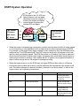
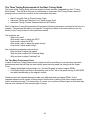
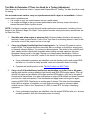
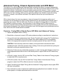
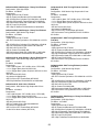
ESPFI System Operation
ECM refers to the VE, AFR and
Spark Advance Look-up tables,
calculates how much oxygen is
entering the engine and sends
output signals to achieve the
desired AFR and Spark.
CKP Sensor
TP Sensor
MAP Sensor
IAT Sensor
Reads
Inputs, etc.
Sends
Outputs
Front and Rear:
Fuel Injectors
and
Ignition Coils
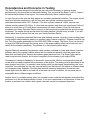
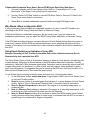
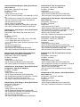
¾ When the engine is experiencing a temporary condition such as when the bike is being started
on a cold morning, it uses additional Look-up tables that are also programmed into the ECM.
For example, a cold engine that’s being cranked to start rotates at a very low RPM and needs
additional fuel. The ECM reads the ET and CKP sensors, which tell it the engine is cold, and
that it’s rotating at cranking speed. The ECM then refers to a Cranking Fuel look-up table and
directs the fuel injectors to remain open longer, (increasing their pulse width) which delivers a
richer air/fuel mixture for starting. It also directs the IAC to open to its programmed number of
steps to allow enough air into the engine for starting and idling.
¾ When the engine starts to run the ECM sees the higher RPM and then refers to a Warmup
Enrichment look-up table that it uses to add the additional fuel needed while the engine is still
cold. The table is designed to diminish its affect, (referred to as “decay value”) to zero as the
engine comes up to operating temperature.
ECM Refers to:
Cranking Fuel Table
When:
Engine is being started
Other Factor:
Engine Temperature
Warm-up Enrichment
Table
Engine is colder than
operating temperature
Idle RPM Table
Throttle is closed
Engine Temperature
Intake Air Control Table
Throttle is closed
Engine Temperature
9
Purpose:
To increase fuel
injector pulse width
and deliver more fuel
for starting
To richen AFR for cold
engine and diminish
effect as engine warms
up
To keep idle RPM at
desired speed as
engine warms up
To allow enough air
into the engine for cold
engine idle
Heat Management System
The ESPFI systems also incorporate a sophisticated heat management system that operates in
three-phases to keep things cool in extreme conditions.
Phase I: If the ECM detects engine temperature above approximately 300° F while moving or
stationary it reduces the idle speed. A lower idle speed produces fewer combustion events per minute
and that reduces engine heat.
Phase II: If the ECM detects an engine temperature that’s still drifting higher while moving or
stationary it richens the AFR. An increased amount of fuel in the air/fuel mixture has a cooling effect
on the engine.
Phase III: If the ECM detects an engine temperature that’s still drifting higher while moving or
stationary it directs the fuel injectors to skip, (only when the bike is stationary) and not deliver fuel on
every intake stroke. This limits the number of combustion events taking place, which produces less
heat.
The three phases just described function seamlessly, and the rider may not notice the transition from
one phase to the next.
Model Year 2007:
For all Big Twin vehicles there is an optional Heat Management System called the ‘Engine Idle
Temperature Management System’ or EITMS. The Tuner software allows the EITMS to be turned
ON/OFF.
For those riders who frequently find themselves in riding conditions where the vehicle is subjected to
prolonged idle conditions the optional ‘Engine Idle Temperature Management System’ (EITMS) is
available. This feature offers limited rear cylinder cooling with the vehicle stopped while the engine is
left at idle.
Enabling EITMS will cause the rear cylinder to be shut OFF when ALL of the following occur:
Engine Temperature reaches ~300F.
And the vehicle is at IDLE.
And the vehicle is STOPPED.
NOTE:
Customer benefits (for Rider Comfort) – If a customer experiences frequent riding conditions where
prolonged idle conditions create excessive engine heat, EITMS offers limited rear cylinder cooling
with the vehicle stopped and engine at idle. While enabled, the customer may notice a unique
exhaust odor which may be objectionable. The EITMS does not address engine heat issues resulting
from other operating conditions.
10
Closed-Loop Operation
Background
In closed loop operation the ECM uses one or more oxygen sensors as a feedback loop in order to
adjust the fuel mixture. This gives the name ‘closed loop’ from the closed feedback loop. The ECM
does not run in a closed feedback loop all the time, so ‘open loop’ is used to describe the operation of
the ECM when the mixture is not being adjusted in this way (usually when the engine is cold or when
running under high load).
In closed loop operation the ECM uses the oxygen sensor to tell if the fuel mixture is rich or lean.
However, due to the characteristics of the oxygen sensor it can’t tell exactly how rich or lean, it only
knows that the mixture is richer or leaner than optimum. The ECM will enrich the mixture if the
oxygen sensor shows that the mixture is lean, and lean the mixture if it looks rich. The result of this is
that the mixture will swing back and forward around the stoichiometric point or the set point of that
particular O2 sensor.
Harley-Davidson Motor Company started using O2 sensors with the 2006 EFI Dyna models and
today all Harley’s use O2 sensors and can operate in ‘Closed Loop’ mode. Harley uses what is called
a narrow band or switching sensor which controls over a very narrow range that is near stoichiometric
(14.5 AFR). In some circumstances the tuner may want to move this control point, and the ability to
do this is accomplished with the Super Tuner by adjusting the Closed-Loop Bias table. This table will
allow moving the O2 set point by about ± 0.5 AFR. Trying to skew the set point by more than ± 0.5
AFR causes the sensor to become inaccurate.
Tuning with Closed-Loop
If a large part of the original calibration’s AFR table reads 14.6 AFR (the cells will show as red
highlighted) then that calibration is indeed closed loop.
The AFR table controls the operating conditions in which the ECM will enable closed-loop. The AFR
cell must equal 14.6 for the ECM to enable closed-loop operation. This allows the user to control if
and when the bike is in closed-loop using the AFR table.
11
Section 3 – Software Installation
The Screamin' Eagle Pro Super Tuner software requires Windows XP (with Service Pack 2) or Vista
or above, with all current Windows updates installed.
The PC must also have an open USB port.
Installation of Screamin' Eagle Pro Super Tuner Software
NOTE: Your Screamin’ Eagle Pro Super Tuner software comes with separate software installation
instructions. If you need more detailed instructions, refer to the software installation instructions that
were included with your software.
Follow these instructions to install the Super Tuner software on a PC running Windows XP SP2 or
Windows Vista:
1.
Exit all Windows programs including screen savers.
2.
Insert the CD-ROM into the drive, label side up.
3.
Setup program will start automatically.
4.
If the software setup program doesn't start automatically follow these steps:
a. From the desktop double -click on my computer.
b. Double -click on CD-ROM drive containing disk.
c. Double -click on Setup.exe
5.
Follow the instructions on the screen to install the software.
NOTE: We recommend that you use the default Destination Directory suggested during the setup.
6.
After you install the Super Tuner software, you may need to reboot the PC.
12
Section 4 – Basic Overview of Super Tuner
Software
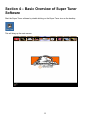
Start the Super Tuner software by double clicking on the Super Tuner icon on the desktop.
This will bring up the main screen.
13
The Main Menu appears at the top of all Super Tuner software screens. It includes several buttons
that allow access to the primary modes of operation. A description of each main menu item appears
below.
Toolbox: Enables a secondary menu of buttons along the left side
of the screen, which provide access to data items and other
diagnostic information.
Tuning: Allows you to customize tuning calibrations to maximize
your motorcycle's performance.
Print: Allows you to load and print reports, data lists and data
displayed on the computer screen.
Reflash: Allows you to change vehicle calibration settings by
reprogramming the vehicle’s Erasable Programmable Read-Only
Memory (EPROM).
Screamin' Eagle Logo: Click on the logo from any screen within the
software to return to the main menu.
Setup: Provides access to user configurable settings:
Language, Color and Units Selection;
Tuning Options;
Workshop Information;
Software Information;
Reprogram VCI;
History Logs.
Help System: Super Tuner software’s online help system. The help
system includes detailed information about software operation and
its various functions.
Minimize Window: Reduces the Super Tuner program to a button
on the Windows “Task Bar” at the bottom of the desktop screen.
Exit Program: Shuts down the Super Tuner program and returns
you to the Windows Desktop.
14
Section 5 – Basic and Advanced Tuning
Basic Tuning
Use both Basic and Advanced Tuning to make edits to calibrations, save the edited file, and then
program (“Reflash”) the ECM with the new calibration.
TIP: Create a log that lists the calibrations you have modified, and for what purpose.
Basic Tuning is the easiest to use for simple tuning tasks and is recommended for those users who
do not have prior experience with Super Tuner tuning. Basic Tuning tables are set up to allow the
user to make changes which are relative to the original factory calibration.
NOTE: When an original calibration file is loaded for editing, the Basic Tuning tables will all show a
value of zero. This is because the Basic tables only allow relative adjustment of the existing values,
and do not display the actual absolute data values.
There are two basic tuning tables provided:
•
Main Fuel Table – use this tuning table to adjust the ECM’s AFR target for both front and rear
cylinders at the same time; a positive value will be richer, while a negative value will be leaner.
Behind the scenes, this is manipulating the Air-Fuel ratio table, but only showing relative
change in percent.
•
Main Spark Table – use this tuning table to adjust the spark advance for both front and rear
cylinders at the same time. A positive value adds more spark advance, while a negative value
removes spark advance. Behind the scenes, this is manipulating the front and rear cylinder
spark advance tables. These tables can be individually accessed in Advanced Tuning.
Additionally, the user can adjust the ECM Tuning Constants:
• edit Engine Displacement setting (if you have changed bore or stroke);
• adjust Fuel Injector rate (if you have changed or modified injectors);
• set engine RPM limit;
• toggle the Knock Sensor ON/OFF;
• turn Temperature Management ON/OFF;
• enable/disable Active Exhaust Control;
• enable/disable Active Intake;
• enable/disable ACR (Active Compression Release).
NOTE: Edits to the Engine Displacement or Injector Size shift the entire fuel calculation.
15
Advanced Tuning
Use both Basic and Advanced Tuning to make edits to calibrations, save the edited file, and then
program (“Reflash”) the ECM with the new calibration.
TIP: Create a log that lists the calibrations you have modified, and for what purpose.
The Advanced Tuning tables allow much greater control over ECM operation, and separate out the
front and rear cylinder functions into individual tables. Advanced Tuning tables display the actual
absolute data values.
There are a total of eleven calibration tables available:
•
Air Fuel Ratio – This table affects the Air-Fuel Ratio Target for BOTH Front & Rear Cylinders
simultaneously. This table charts AFR vs. MAP and Engine RPM.
o Increases make the AFR Target leaner (leaner = less fuel).
o Decreases make the AFR Target richer (richer = more fuel).
•
Volumetric Efficiency (VE) Front and Rear Cylinders – The VE Tables tell the ECM the air
flow efficiency of each cylinder in percent. This table charts VE percent vs. throttle position
(TPS) and engine RPM.
o Increases raise the VE, implying there is more air entering the cylinder.
o Decreases lower the VE, implying there is less air entering the cylinder.
•
Spark Advance Front and Rear Cylinders – The Spark Advance Tables control the spark
timing of each cylinder independently. This table charts ignition Timing in degrees Before Top
Dead Center vs. MAP and engine RPM.
o Increases Advance the spark timing.
o Decreases Retard the spark timing.
•
Warm-up Enrichment – The Warm-up Enrichment Table tells the ECM to deliver additional
fuel to both cylinders as the engine is warming up. This table charts AFR adjustment to the
target value vs. engine temperature.
o Increases add fuel during warm up.
o Decreases remove fuel during warm up.
TIP: Use Warm-up Enrichment Table to adjust the cold engine to warm engine performance.
Increase fuel to correct engine coughing and surging during engine warm-up. Decrease fuel to
correct overly rich conditions evidenced by black exhaust smoke during engine warm-up.
•
Cranking Fuel – The Cranking Fuel table controls the fuel injector pulse width (BPW) to both
injectors while the engine is being started. This table charts injector pulse width vs. engine
temperature.
o A longer pulse delivers more fuel.
o A shorter pulse delivers less fuel.
TIP: Use Cranking Fuel Table to correct hard starting problems of engines in warm-up mode
by increasing/decreasing the fuel delivered for starting. Engines that are hard starting usually
require more fuel.
16
•
Idle RPM – The Idle RPM table controls the idle speed as the engine warms up. This table
charts idle RPM vs. engine temperature.
•
IAC Warm-up Steps – The IAC Warm-up Steps table is used to provide an additional amount
of air to the engine for its first several minutes of operation.
o Higher numbers increase airflow to the engine at idle.
o Lower numbers decrease airflow to the engine at idle.
TIP: Use IAC Warm-up Step Table to improve engine idle performance during warm-up
If engine RPM increases and then decreases just after start up, IAC steps may be set too high
for this engine temperature. If engine RPM dips and then increases just after start up, IAC
steps may be set too low for this engine temperature.
•
Acceleration Enrichment (AE) – The Acceleration Enrichment table allows the addition of a
small amount of fuel during an increase in throttle position, or during an increase in manifold
pressure. This fuel gets added to the base pulse width calculation.
o Larger values increase the fuel added.
o Smaller values decrease the fuel added.
•
Deceleration Enleanment (DE) – The Deceleration Enleanment table allows the removal of a
small amount of fuel during a decrease in throttle position, or during a decrease in manifold
pressure. This fuel gets subtracted from the base pulse width calculation.
o Larger values increase the fuel removed.
o Smaller values decrease the fuel removed.
•
Closed Loop Bias – The Closed Loop Bias table skews the AFR from the nominal 14.6 AFR
value. AFR can be skewed approximately ± 0.5 AFR.
o Lower values will cause a leaner AFR.
o Higher values will cause a richer AFR.
Additionally, the user can adjust the ECM Tuning Constants:
• edit Engine Displacement setting (if you have changed bore or stroke);
• adjust Fuel Injector rate (if you have changed or modified injectors);
• set engine RPM limit;
• toggle the Knock Sensor ON/OFF;
• turn Temperature Management ON/OFF;
• enable/disable Active Exhaust Control;
• enable/disable Active Intake;
• enable/disable ACR (Active Compression Release).
NOTE: Edits to the Engine Displacement or Injector Size shift the entire fuel calculation.
17
Section 6 – Toolbox
Data Items
Data Items allows you to select specific items of data to view such as spark advance, engine speed,
battery voltage and so forth.
Examine these items as numerical values in the Data List, and on a graph. The data items are
displayed in “real time” as the motorcycle is running.
You may also “record” the data as it is retrieved from the motorcycle’s ECM and displayed. You may
then playback the recording, stepping forward or back through the data a “frame” at a time. When
viewing recorded data, you may also use the Quarter Mile and Speed/Distance calculators.
Use the information in Data Items to diagnose tuning opportunities, or as a tool to identify anomalies
that may have occurred during the recorded event that may be contributing to poor performance.
There are currently 20 data items that Data Items records for display as follows:
•
Acceleration Enrichment – Acceleration Enrichment ('AE') is a measure of how much
additional fuel is added during vehicle acceleration. AE is generated by increasing the injector
pulse width slightly. The resolution is 0.01 mS, and the range is 0 to 262 mS.
•
Air Fuel Ratio (AFR) – Air-fuel ratio determines how rich or lean the engine is running. 14.7:1
is considered the most efficient AFR, while more power will be produced for lower (richer)
values. The AFR resolution is 0.1, and the range is 0 to 25.5. Note that a cold engine requires
a lower (richer) AFR to operate smoothly. The typical operating range is 12.5 to 14.7, although
during cold start-up the mixture may be momentarily a low as 8.
•
Battery Voltage – Battery Voltage (Volts) is monitored at the ECM. The resolution is 0.1 volts,
and the range is 0 to 25.5 Volts. The nominal value will vary depending on temperature, load,
and battery condition, and should be in the range of 12.6 to 15 volts.
•
Deceleration Enleanment – Deceleration Enleanment ('DE') is a measure of how much fuel is
removed during vehicle deceleration. DE fuel is typically removed during coasting or engine
overrun to improve fuel efficiency and reduce emissions. DE is generated by decreasing the
injector pulse width slightly. The resolution is 0.01 mS, and the range is 0 to 262 mS. Note that
under some conditions, fuel may be entirely cut-off.
•
Desired Idle – The table value for Idle RPM at that engine temperature.
•
Engine RPM – The engine RPM reads out with a resolution of 1 RPM.
•
Engine Temperature – Engine Temperature is measured at the cylinder head and is displayed
in both degrees Centigrade and Fahrenheit. The resolution is 1 degree C, and the range is -16
to +239 degrees C.
18
•
Idle Air Control Position – Idle Air Control ('IAC') position is measured in steps. The value will
range form 0 to 255 steps depending on engine operating mode.
•
Injector Pulse Width (Front and rear cylinders) – Injector Base Pulse Width (BPW) is measured
in milliseconds (mS, 0.001 seconds). The resolution is 0.01 mS, and the range is 0 to 262 mS.
The BPW directly affects the fuel mixture, and may be different for the front and rear cylinders.
•
Intake Air Temperature – Intake Air Temperature (‘IAT’) is measured at the intake manifold
and is displayed in both degrees Centigrade and Fahrenheit. The resolution is 1 degree C, and
the range is -16 to +239 degrees C.
•
Knock Retard (Front and rear cylinders) – Spark Knock Retard is a measure of how much
timing was REMOVED due to engine knock being detected. The resolution is 0.5 degrees, and
the range is 0 to 20 degrees. Typically, you do not want to see more than 2-3 degrees here,
values higher than this indicate either:
•
Manifold Pressure – Manifold Pressure (MAP) is analogous to 'engine vacuum'. For EFI
engines, MAP is measured in absolute units of pressure, kPa (kilo Pascals). The resolution is
0.4 kPa, and the range is 10.3 to 104.4. Note that 0 kPa is a perfect vacuum, while 100 kPa is
approximately atmospheric pressure.
o Barometric Pressure – Barometric Pressure ('BARO') is measured by the MAP sensor
immediately before engine startup and under various conditions while the vehicle is
running. It is a measure of the absolute air pressure (just like the weather report). BARO
is measured in absolute units of pressure, kPa (kilo Pascals), the resolution is 0.4 kPa,
and the range is 10.3 to 104.4 A typical value at sea level is 100 kPa, while 80 kPa is
possible at high altitudes.
•
Spark Advance (Front and rear cylinders) – Spark Advance is reported in degrees before Top
Dead Center (BTDC). The resolution is 0.25 degrees, and the displayed range can be -4 to
+99 degrees. Typical operating range is 0 to 50 degrees. Note that the front and rear cylinders
may use different timing values!
o The engine is too hot
o The gas octane is low
o The mixture is too lean
o The timing is too far advanced
•
Throttle Position – The throttle position is displayed in Volts (0 to 5.00) and in percent open (0
to 100 percent).
•
Vehicle Speed – The vehicle speed is displayed in both MPH and in km/hr. The resolution is 1
km/hr and the range is 0 to 255 km/hr.
•
Volumetric Efficiency (Front and rear cylinders) – Volumetric Efficiency (VE) is a measure of
how efficiently the engine can pump air. The resolution is 0.5 percent, and the range is 0 to
127.5 percent. VE as reported by Tuning is the value the ECM is currently using to calculate
fuel delivery. Engine speed, camshaft profile, cylinder head design, and intake/exhaust
manifold design all influence this value.
19
•
Warm-up Fuel – Warm-up Fuel is added when the engine is first cold started, and reduced as
the engine warms up. It is a measure of percent change to the fuel mixture with positive values
being richer. The resolution is 0.4 percent, and the range is 0 to 100 percent.
With oxygen-sensor equipped vehicles, six additional data items are recorded:
•
O2 Integrator Value (F & R cylinders) – For Oxygen-sensor equipped vehicles, the O2
Integrator indicates the deviation from the ideal fuel mixture over a few seconds time. A 100%
value means the AFR is exactly as expected, while higher values indicate the mixture is Lean
and lower values indicate the mixture is Rich.
•
O2 Sensor Voltage (F & R cylinders) – For Oxygen-sensor equipped vehicles, the O2 sensor
voltage is reported. This will be a value between 0 and 5100 mV.
•
VE New Value (F & R cylinders) – For Oxygen-sensor equipped vehicles, VE New is what the
Volumetric Efficiency table value should be, based on A/F feedback.
Quarter Mile and Speed/Distance Calculators
NOTE: The Quarter Mile and Speed/Distance calculators are only available if you are viewing
recorded data.
The Quarter Mile time estimator calculates the times to 60 feet, 1/8 and 1/4 mile during an
acceleration run, as well as zero-to-60 times. This calculator uses a linear interpolation of the speed
data between sample points to improve the accuracy of the time to speed and distance values.
The Speed/Distance Calculator calculates the distance traveled between any two points of a
recorded data event. Also calculated are the average acceleration and elapsed time for the defined
distance.
Record VCI Data
This function allows you to record data from the motorcycle's ECM using the VCI.
Diagnostic Trouble Code (DTC) Display
The Diagnostic Trouble Codes (DTCs) screen displays current and historic fault codes, along with
descriptions and possible causes.
System Information
The System Information function displays important identification data for the ECM installed on the
motorcycle.
20
Section 7 – Race Tuning Guide
Introduction to Race Tuning
The Screamin' Eagle Pro Super Tuning system will provide you with the tools to tune a fuel injected,
performance-enhanced Harley-Davidson Twin Cam engine for optimum performance. It has the
flexibility to be used as a simple fuel and spark timing adjustment device or as an engine data
acquisition tool with the ability to make specific, detailed adjustments to several different tuning tables
within the ECM.
What Can the Screamin' Eagle Pro Super Tuner Do for Me?
Until now, the customer who wanted to enhance the racing performance of their Fuel Injected Twin
Cam equipped Harley-Davidson would install a Screamin' Eagle Stage I or Stage II Calibration to
match the engine configuration of the bike; both to optimize performance and protect the engine from
damage. There was no effective way to fine-tune the EFI system to achieve the “edge” that wins
races, and there was no effective way to tune the ECM for engine configurations that were different
than what was currently offered. That’s where the Screamin' Eagle Pro Super Tuner comes into play.
When the racer modifies any area of the engine that affects engine performance (cylinder heads,
intake components, exhaust components, engine displacement, cylinder compression or cam profile),
the ECM Tuning tables will require adjustment to fully realize the performance potential of the
modified engine and prevent potential engine damage.
With the Screamin' Eagle Pro Super Tuner the user can edit up to eleven different ECM tuning tables
that affect fuel delivery and spark timing. That means the user can adjust the calibration of the ECM
to optimize fuel delivery or spark timing to each individual cylinder. The Super Tuner provides the
user with tools and data that are very similar to what Harley-Davidson’s engineers use to create the
Screamin' Eagle Performance Calibrations.
What Can This Race Tuning Guide Do for Me?
This guide will provide you with a foundation for tuning EFI systems that have been enhanced with
Screamin' Eagle performance accessories. It cannot, however provide detailed answers for every
possible scenario. Fine-tuning the ECM of a Screamin' Eagle equipped engine usually requires only
minor adjustments. Before reading further, please read Section 1 - Introduction. This section
describes the design and function of the current Harley-Davidson EFI system. You’ll need to fully
understand how the EFI system functions, to be able to tune it successfully.
21
The Three Tuning Environments of the Race Tuning Guide
The layout of the Tuning Guide will be arranged into three sections, separated into their “Tuning
Environment”. This will allow the user to concentrate on one area of the Tuning Guide, instead of
jumping from one section to another for the information they need.
•
•
•
Basic Tuning By Feel on Closed-course Track
Advanced Tuning and Data Items on Closed-course Track
Advanced Tuning, Chassis Dynamometer and AFR Meter
Each of the three Tuning Environments will contain the following information, provided in the form of a
question. The answers will relate to the specific Tuning Environment so the user can focus on one
section of the Tuning Guide for their particular situation.
The questions are:
Where do I start?
Why would I want to adjust the AFR?
How would I adjust the AFR?
Why would I want to adjust the spark timing?
How would I adjust spark timing?
Also included are separate sections about:
Why and how to adjust idle speed.
Why and how to adjust IAC Warmup Steps.
Why and how to adjust Cranking Fuel.
The Two Basic Performance Tests
In each of the three Tuning Environments, directions will be provided on how to perform two basic
performance tests that will help the user identify areas that may need fine-tuning with the Super
Tuner:
• Steady throttle/light load cruising in 1st, 3rd and 5th gears at various engine RPMs.
• Full throttle/heavy load Roll-on acceleration runs in 2nd, 3rd or 4th gears starting at 2000 RPM
and safely accelerating to the engine’s redline.
These two tests will operate the engine under very different loads and engine RPMs. This is
important because most venues of racing require that the bike is able to both hold a steady throttle
and to accelerate strongly. The tuners may, of course, opt to perform different types of tests that they
feel are more relevant to their intended type of racing.
22
Consistencies and Concerns in Testing
The Super Tuner was designed to provide the user with tools necessary to optimize engine
performance by fine-tuning the fuel and spark delivery. But, as good as the Super Tuner is, it cannot
fix mechanical problems in the engine. You cannot effectively tune a troubled engine.
It’s up to the user to be sure that their engine is in excellent mechanical condition. The engine should
have good cylinder compression, with the front and rear cylinder cranking compression
measurements equal within 10%. Example: If the front cylinder measures 145psi, then the rear
cylinder should produce 130-160psi. If a front and rear cylinder leak-down test is performed it should
result in no more than a 10% leak-down measurement for either cylinder. Follow the instructions
provided in the Harley-Davidson Service manual or the instructions provided with the specific testing
equipment. The engine should also be tested for intake manifold, (throttle body) air leaks. If you are
unsure about how to perform this test, see your Harley-Davidson Dealer.
Additionally, it should be mentioned that some open exhaust systems, (typically known as drag pipes)
on the market today contribute greatly to a situation called “exhaust reversion”. Exhaust reversion can
limit Twin Cam engine performance in the 2000-4000 RPM rev range. The Super Tuner can be used
to target this RPM and through fine-tuning, some of this power-robbing effect can be reduced, but it
cannot fix the situation completely. The problem is in the exhaust system design.
Engines fitted with extremely long duration cams can also contribute to intake and exhaust reversion
problems due to the overlap condition where both the intake and exhaust valves are open at the
same time and trading fuel, fresh air and exhaust gases back and forth. The Super Tuner can be
used to improve this situation, but it cannot completely fix the situation in all engine RPMs.
Consistency in testing is mandatory for successful tuning results. Without consistency the tuner will
not be able to properly measure the performance of the engine. The testing must be performed in the
same manner every time. For example, when testing a bike on the chassis dynamometer, the “road
conditions” are controlled, but the user may mistakenly test the bike with the engine in different states
on comparison tests. Example: If the bike was tested at operating temperature on one test, and
tested again when the bike is cool and still in the warm-up mode on another, the two tests are not
comparable due to different engine conditions.
Another factor in consistent testing, when on a closed-course, is that the acceleration tests should be
performed on a flat and straight section of track. If one test is performed on a flat section of track and
another is performed on a section with a grade, the tests cannot be compared objectively.
23
Checklist of Consistency Concerns
9 The motorcycle must be track-worthy – for the rider’s safety and the safety of others a pre-ride
inspection must be performed following the guidelines provided in the Harley-Davidson Factory
Service Manual for the bike being tested.
9 The primary and secondary drives must be adjusted to Factory specification and at the same
tension for every test. Differences in primary or secondary drive adjustment can vary the
amount of frictional losses between tests and cause inconsistent performance measurements.
9 The front and rear tire pressure should be set to the Factory specification and must be the
same pressure for every test or the frictional losses may vary and cause an inconsistent
performance measurement.
9 The engine must be at operating temperature and the Warmup Enrichment mode must be
inactive or the performance measurements will vary from test to test.
9 The fuel the bike is running on should be fresh and it is recommended that the same type of
fuel is used for comparison tests or the performance measurements may vary.
9 Wind and road surface conditions on the closed-course track being used for testing should be
the same for every test or the performance test measurements will be inconsistent. The
closed-course track environment should allow for a safe testing event.
9 If a chassis dynamometer is used for testing it should be operated according to the instructions
provided by the chassis dynamometer manufacturer to produce consistent performance
measurement results.
Explaining Air-Fuel Ratio
The Air-Fuel Ratio (AFR) of an engine is determined as the weight ratio of the air entering the engine
in relation to the amount of fuel being mixed with the air that creates a combustible mixture. The
stoichiometric AFR is 14.7 to 1, (14.7 grams of oxygen to 1 gram of fuel). Stoichiometric means that a
ratio of 14.7 grams of oxygen to 1 gram of fuel, when burned, will theoretically result in complete
combustion. Stoichiometric isn’t the only AFR that supports combustion. Most engines, including
Harley-Davidson Twin Cam models, will run with rich AFRs of about 8 to 1 (more fuel) up to lean
AFR’s of about 15 to 1 (less fuel).
When does an engine need a rich fuel mixture? It needs a rich fuel mixture to start a cold engine and
to achieve peak power under heavy load. Cold engines need extra fuel because it’s only the fuel
vapor that will ignite and burn, not the fuel liquid. When the engine is cold the fuel tends to condense
on the walls of the intake manifold and cylinders (like water condensation on a cold window).
Additional fuel is needed to provide enough fuel in vapor form to start and run the engine. The cold air
also contributes to the need for more fuel because the gases in the air contract when it’s cold and
that means there’s more oxygen in a given volume of air entering the engine, creating a leaner
mixture than normal. Engines under heavy load create more heat in their combustion chambers
because of the additional stress. Heavy loads also lower the engine’s intake manifold vacuum, which
can cause some of the fuel to drop out, or puddle in the manifold. The extra fuel of a rich mixture
helps to cool the engine and to provide enough fuel to support combustion when some of the fuel
drops out.
24
When can an engine run on a lean mixture? The engine can run on lean mixtures of say, 15 to 1,
when the engine is fully warmed up and being operated under light loads, such as when holding a
steady throttle, steady speed on a flat stretch of track. A hot engine though, under severe load, (such
as in top gear, and accelerating for a speed record), could have a tough time running on a lean
mixture, and could overheat to the point of causing itself severe damage. As a rule of thumb, for:
•
•
•
Peak power a 12.8 to 1 AFR is preferred;
Severe loads a 11.0 to 1 AFR is preferred;
Cruising under light load a 14.0 to 1 AFR is preferred.
These AFRs are all approximate and your results may vary slightly.
Why Would I Want to Adjust the AFR?
Each motorcycle (and each cylinder of an engine) has its own unique requirement for the amount of
fuel that would achieve maximum performance. That’s where the Screamin' Eagle Pro Super Tuner
system comes in. It provides the tools necessary to adjust the AFR in the exact engine RPM and
engine load needed to unleash the potential of virtually any performance-enhanced Harley-Davidson
Twin Cam engine.
Symptoms of a Rich or Lean AFR
The tuner should be familiar with the symptoms of an overly rich or overly lean AFR. The symptoms
are the signal to us that we have not achieved maximum performance – that we need to adjust the
EFI.
Lean running symptoms
• Bike hesitates when throttle is increased
• Bike runs jerky or surges at steady throttle openings
• Engine detonates, (knocks) when accelerating
• Engine spits back or coughs through intake system
• Exhaust pipe deposits are light gray in color
• Bike runs poorly when cold – engine runs better as it warms up to operating temperature
• Spark plug color is white
• Fuel consumption is abnormally low
Rich running symptoms
• Engine blubbers when throttle is increased
• Bike emits black exhaust smoke, (a little black exhaust smoke is normal when accelerating
hard or operating engine when cold)
• Exhaust pipe deposits are dark, or black in color
• Engine blubbers at steady throttle
• Engine fouls spark plugs
• Bike runs well when cold – engine runs worse as it warms up to operating temperature
• Spark plug color is black
• Fuel consumption is abnormally high
25
Basic Tuning By Feel on Closed-Course Track
This section is for those users who plan on measuring the performance of the bike by feel and
observation, not by Data Item recording or dynamometer and AFR measurement. Tuning by feel can
provide successful results, but the user should realize that tuning in this manner will be more “broadbrush” because it will be impossible to target the exact RPM and engine load where AFR or spark
timing adjustment is needed.
Overview - Tuning By Feel
¾ Inspect and prepare bike for testing.
¾ Test bike and determine if the symptoms indicate a need for tuning adjustment.
¾ Adjust the AFR or Spark Timing with the Basic Tuning feature of the Super Tuner to achieve
the performance desired.
¾ Retest bike to determine if additional tuning adjustments are needed.
Where do I start?
Start by making sure the bike is safe to ride, the engine is in excellent condition and the best
Screamin' Eagle Tuning file is programmed into the ECM. Read on:
Inspect and Prepare Bike for Testing
1. Perform a thorough inspection of the bike before performance testing by following the
directions provided in the Maintenance section of the Official Harley-Davidson Service
manual for your vehicle. You must make sure the bike can be safely ridden before performing
any tests. If you are not sure that you can perform this inspection properly, then the
motorcycle should be inspected and serviced by a Harley-Davidson dealership technician. Do
not take chances with your safety or the integrity of the motorcycle.
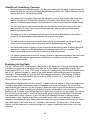
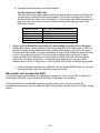
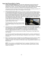
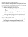
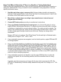
2.
Temporarily label the throttle assembly on the bike to identify when the throttle is at the 0,
6, 12, 25, 50 and 100% position. This will help the rider identify what range of MAP (Manifold
Absolute Pressure) the engine is operating in when performing the test. The picture below
shows a throttle assembly with pieces of tape applied to the right side switch housing and the
throttle grip itself. Mark a single arrow on the switch housing tape and then mark the 0% (idle
or closed) position and the 100% (WOT position) with a dash and number. The midpoint is
50% and should be marked with a dash and number. Mark the midpoint between 0 and 50 as
25, the midpoint between 0 and 25 as 12 and the midpoint between 0 and 12 as 6.
The throttle position marks will
correspond roughly with the MAP
readings in the table provided in this
section.
26
3.
If you haven’t done so already, program the ECM with the Screamin' Eagle Tuning
calibration that best matches the performance components installed on your motorcycle.
Example: If you own a 2002 Softail and you have installed the components of the 1550 Stage
II with Screamin' Eagle Performance Heads kit, you would program the ECM with tuning
calibration number 105HD019. Follow the instructions in the Super Tuner online help.
If you don’t know which calibration would be the best match for your bike, search the list of
Screamin' Eagle Calibration Files with their engine configuration notes in Section 8 –
Calibration Information.
4.
Disable Knock Control using the ECM Tuning Constants selection in the Basic Tuning. This
will turn the ECM’s Ion Sense feature off and the ECM will not retard spark timing if
detonation is present. If the AFR is too lean or the spark timing is too advanced and causing
detonation the test rider will be more able to sense this as an audible engine knocking on
acceleration under load.
NOTE: Remember to Enable Knock Control when your tuning session is completed. This will
ensure that the engine receives an extra measure of protection.
Test Bike to Determine if There Is a Need for a Tuning Adjustment
After following the directions listed in Inspect and Prepare Bike for Testing, the bike should be ready
for testing.
Use a closed-course track to carry out a performance test if a dyno is not available. A closed
course track is used because:
•
It is unsafe to carry out a performance test on a public street.
•
It is unsafe and illegal to carry out some performance tests that may require the rider to
exceed the speed limits of public streets.
NOTE: It is illegal to operate a motorcycle with certain performance accessories, including, but not
limited to the Screamin' Eagle Pro Super Tuner system because some performance accessories are
for Race Use Only.
1.
Start bike and allow engine to warm-up fully. Engine cylinders should be hot enough to
feel heat if hand is placed within 1-inch of fins. Use care to avoid being burned. Listen to idle
and make a note if idle seems too low or too high.
2.
Carry out a Steady throttle/Light load cruising test in 1st, 3rd and 5th gears at various
engine RPMs. The engine should run smoothly with no misfires, no bucking or surging and
no unusual exhaust rhythms. Try cruising at various speeds. The ability to run smoothly with
light, steady throttle is particularly important when holding a steady speed as the racer
navigates a broad curve in the track. Racing is not always about acceleration. Refer to the
Symptoms of a Rich or Lean AFR for help in identifying symptoms.
a. If any undesirable symptoms are identified, note the throttle position and engine RPM
the bike is in. As soon as safely possible, write this information down for tuning.
27
b. Compare the throttle position to the table below.
Throttle Position vs. MAP Table
This table provides a rough guide to matching throttle position to engine load. Note that
a broad range is listed in some throttle positions. This is due to the amount of load on
the bike at that time. More Load = More MAP. To identify the exact MAP the symptom is
present in, the user will need to record the performance test using the Super Tuner
Data Items function.
Throttle Position
0-6%
12%
25%
50%
50-100%
3.
MAP- (Manifold Absolute Pressure)
10-50 kPa
40-55 kPa
55-90 kPa
90-100 kPa
90 and higher kPa
Carry out a Full throttle/Heavy load Roll-on acceleration run in 2nd, 3rd or 4th gears
starting with the bike cruising steady at light throttle and 2000 RPM engine speed. Then roll
throttle fully open and accelerate until engine reaches RPM redline, (only test in 4th gear if
closed-course track allows for a safe acceleration to engine RPM redline and doesn’t exceed
your limit for a safe road speed). Then decelerate and apply brake until engine is again
running at 2000 RPM. Repeat test in another gear if desired. The bike should accelerate
briskly with no misfires or hesitation, no loud engine knocking and no excessive black
exhaust smoke. Refer to “Symptoms of a Rich or Lean AFR for help in identifying symptoms.
¾ If any undesirable symptoms are identified, note the engine RPM the bike is in. As soon
as safely possible, write this information down for tuning.
Why would I want to adjust the AFR?
If your performance tests indicated any undesirable symptoms of a rich or lean AFR condition you
should adjust the ECM Tuning Tables with the Super Tuner Basic Tuning feature.
If the bike exhibited no undesirable symptoms and you want to see if you can improve the
acceleration performance, you can adjust the ECM Tuning Tables with the Super Tuner Basic Tuning
feature.
28
How would I adjust the AFR?
You should already have read the closed-course track testing instructions and performed
both the steady throttle and full throttle tests and determined what (if any) symptoms you felt you
wanted to correct, along with the engine RPM and MAP the symptoms are present in.
Example 1: A Steady Throttle test showed a surging symptom, indicating a lean AFR at about 6%
steady throttle around 2500 RPM with the bike under a light engine load. In this example you would:
1.
Consult the Throttle Position vs. MAP Table and see that MAP runs a wide range of 10-50
kPa, but you know the load was light so you focus on the lower numbers.
2.
The suggested tuning for a lean condition like this is to use the Basic Tuning Main Fuel
Table to increase the percentage of fuel delivered at 2250 to 2750 RPM from the lowest MAP
to about 30 kPa. Increase an increase by 2-5 units. Program the ECM with the new Tuning
Table and carry out another performance test.
Example 2: In a Full Throttle Test you hear engine knocking at 2000 to 6000 RPM under heavy
load, indicating: 1) a lean AFR or 2) over-advanced spark timing or 3) a lean AFR and over-advanced
spark timing.
In this example you’ll want to determine if the AFR or the spark timing was causing most of the
engine knocking. Start by looking for additional symptoms of a lean AFR such as light-gray colored
exhaust pipe deposits, light colored spark plugs or that the engine seems to be running very hot. If
you don’t know which of the three causes (AFR, spark timing or both) are the main reason the engine
is knocking, then you’ll want to either increase the fuel delivered or decrease the spark timing in
separate tuning adjustments. Only change one item at a time.
In our example we’ll assume that the exhaust pipe deposits inside the end of the pipe were a very
light gray, indicating a lean AFR. We would then:
1.
2.
3.
Consult the Throttle Position vs. MAP Table and see that the MAP at 100% throttle runs
from 90 kPa and higher.
Use the Basic Tuning Main Fuel Table to make the suggested tuning adjustments for a lean
condition like this by increasing the percentage of fuel delivered at 2000 to 6000 RPM and 90
kPa to 100 kPa MAP. Increase an increase in fuel by 2-5 units.
Program the ECM with the new Tuning Table and carry out another performance test.
If this tuning adjustment had no or little effect on engine knocking, then retard the spark timing (see
How Would I Adjust Spark Timing?).
29
Why Would I Want to Adjust the Spark Timing?
If your performance tests indicated undesirable symptoms such as excessive engine knocking,
sluggish acceleration or the miles per gallon, (mpg) indicated excessive fuel consumption, you should
adjust the spark timing with the Super Tuner Basic Tuning Main Spark Table.
If the bike exhibited no undesirable symptoms, but you want to see if you can improve the
acceleration performance you can adjust spark timing with the Super Tuner Basic Tuning Main Spark
Table.
How Would I Adjust Spark Timing?
You should already have read the closed-course track testing instructions and performed
both the steady throttle and full throttle tests and determined what, if any symptoms you felt you
wanted to correct. And, you should have determined what area of the engine RPM and MAP these
symptoms were present in.
Example 1: Steady Throttle opening of 6% at 2000-4000 RPM under light load indicates no
undesirable symptoms, but fuel consumption is high. This situation is probably telling us that we
need to increase spark timing so that the engine is more efficient. We know that at steady throttle
openings of about 6% that the MAP is between 10-50 kPa because we consulted the Throttle
Position vs. MAP Table.
1.
The suggested tuning for this “retarded spark timing” condition is to use the Basic Tuning
Main Spark Table to increase the spark timing in the 2000 to 4000 RPM range from the
lowest MAP to 50 kPa. We will Increase an increase by 10-Units because we want to change
the spark timing by about 2-4 degrees at a time.
2.
Program the ECM with the new Tuning Table and carry out another performance test.
Example 2: Full Throttle, heavy load Roll-on acceleration run from 2000-5000 RPM produced
excessive engine knock, indicating excessive spark timing. This symptom may be caused by: 1)
over-advanced spark timing, 2) a lean AFR or 3) an over-advanced spark timing and a lean AFR.
In this example you’ll want to determine if the AFR or the spark timing was causing the engine
knocking. Start by looking for additional symptoms of a lean AFR such as light-gray colored exhaust
pipe deposits, light colored spark plugs or that the engine seems to be running very hot. If you don’t
know which of the three causes (AFR, spark timing or both) are the main reason the engine is
knocking, then you’ll want to either increase the fuel delivered or decrease the spark timing in
separate tuning adjustments. Only change one item at a time.
30
For this example we’ll assume that the color of the exhaust deposits is black, indicating a rich AFR
and that over-advanced spark timing is the likely cause of the engine knocking. We know that at WOT
under heavy load that the MAP is 90 kPa and higher because we consulted the Throttle Position vs.
MAP Table.
1.
The suggested tuning for this “overly advanced spark timing” condition is to use the Basic
Tuning Main Spark Table to decrease the spark timing in the 2000 to 5000 RPM range from
the 90 to 100 kPa MAP. We will Decrease a decrease by 10-Units because we want to
change the spark timing by about 2-4 degrees at a time.
2.
Program the ECM with the new Tuning Table and carry out another performance test.
What Do I Do if the Starting, Idle or Warm-up Performance Needs Adjustment?
If you experience a situation with the starting, idle or warm-up performance that you want to remedy,
refer to the section titled: “Miscellaneous Tuning” at the end of this Tuning Guide.
31
Advanced Tuning and Data Items on Closed-Course Track
This section is for those users who plan on testing the bike on a closed-course track and measuring
engine performance with the Screamin' Eagle Pro Super Tuner Data Items function. With the Data
Items function, the user can view ECM engine data as either numbers or graphs and use functions
such as the Quarter Mile Calculator to determine the value of their adjustments to the tuning tables.
Recording and reviewing ECM engine data with Data Items can be a very effective method of
pinpointing the Tuning tables and particular tuning cells that need adjustment.
Overview - Tuning With Data Items and Advanced Tuning
¾ Inspect and prepare bike for testing.
¾ Carry out the 2-basic performance tests: Steady Throttle/Light Load and Full
Throttle/Heavy Load Roll-on acceleration run, to determine if there are any undesirable
symptoms or a lack of power that indicates a need for a tuning adjustment.
¾ If undesirable symptoms or a lack of power are noticed, connect computer to vehicle to
record ECM engine data using the Super Tuner Data Items function.
¾ Retest bike.
¾ Review ECM engine data using Data Items and determine what ECM Tuning Tables
you want to adjust.
¾ Adjust fuel delivery with Basic or Advanced Tuning. Advanced Tuning will allow
individual adjustment of the front and rear cylinders.
¾ Adjust Spark Timing with the Basic or Advanced Tuning. Advanced Tuning will allow
individual adjustment of front and rear cylinder spark timing.
¾ Retest bike to determine if additional tuning adjustments are needed.
Where do I start?
Start by making sure the bike is safe to ride, the engine is in excellent mechanical condition and the
best Screamin' Eagle Tuning file is currently programmed into the ECM.
32
Inspect and Prepare Bike for Testing
1.
Perform a thorough inspection of the bike before performance testing by following the
directions provided in the Maintenance section of the Official Harley-Davidson Service
manual for your vehicle. You must make sure the bike can be safely ridden before performing
any tests. If you are not sure that you can perform this inspection properly, then the
motorcycle should be inspected and serviced by a Harley-Davidson dealership technician. Do
not take chances with your safety or the integrity of the motorcycle.
2.
Temporarily label the throttle assembly on the bike to identify when the throttle is at the 0,
6, 12, 25, 50 and 100% position. This will help the rider identify what range of MAP (Manifold
Absolute Pressure) the engine is operating in when performing the test. The picture below
shows a throttle assembly with pieces of tape applied to the right side switch housing and the
throttle grip itself. Mark a single arrow on the switch housing tape and then mark the 0% (idle
or closed) position and the 100% (WOT position) with a dash and number. The midpoint is
50% and should be marked with a dash and
number. Mark the midpoint between 0 and 50 as
25, the midpoint between 0 and 25 as 12 and the
midpoint between 0 and 12 as 6.
The throttle position marks will correspond roughly
with the MAP readings in the table provided in this
section.
3.
If you haven’t done so already, program the ECM with the Screamin' Eagle Tuning File
that best matches the performance components installed on your motorcycle. Example: If you
own a 2002 Softail and you have installed the components of the 1550 Stage II with
Screamin' Eagle Performance Heads kit, you would Program the ECM with Tuning file
number 105HD019. Follow the instructions in the Basic Tuning section of the Super Tuner
User’s Manual.
If you don’t know which Tuning File would be the best match for your bike, search the list of
Screamin' Eagle Tuning Files with their Engine Configuration notes in Section 9 - Calibration
Information.
4.
Make sure that Knock Control is Enabled using the ECM Tuning Constants selection in Basic
Tuning. The Ion Sense feature should be on so that the ECM will retard spark timing if
detonation is present. You can also use Data Items to spot tuning needs by looking for Knock
Retard activity.
NOTE: If for any reason you disabled Knock Control, remember to Enable Knock Control
when your tuning session is completed. This will ensure that the engine receives an extra
measure of protection.
33
Test Bike to Determine if There Is a Need for a Tuning Adjustment
After following the directions listed in “Inspect and Prepare Bike for Testing,” the bike should be ready
for testing.
Use a closed-course track to carry out a performance test if a dyno is not available. A closed
course track is used because:
• It is unsafe to carry out a performance test on a public street.
• It is unsafe and illegal to carry out some performance tests that may require the rider to
exceed the speed limits of public streets.
NOTE: It is illegal to operate a motorcycle with certain performance accessories, including, but not
limited to the Screamin' Eagle Pro Super Tuner system because some performance accessories are
for Race Use Only.
1.
Start bike and allow engine to warm-up fully. Engine cylinders should be hot enough to
feel heat if hand is placed within 1-inch of fins. Use care to avoid being burned. Listen to idle
and make a note if idle seems too low or too high.
2.
Carry out a Steady throttle/Light load cruising test in 1st, 3rd and 5th gears at various
engine RPMs. The engine should run smoothly with no misfires, no bucking or surging and
no unusual exhaust rhythms. Try cruising at various speeds. The ability to run smoothly with
light, steady throttle is particularly important when holding a steady speed as the racer
navigates a broad curve in the track. Racing is not always about acceleration. Refer to
“Symptoms of a Rich or Lean AFR” earlier in this section for help in identifying symptoms.
a. If any undesirable symptoms are identified, note the throttle position and engine RPM
the bike is in. As soon as safely possible, write this information down for tuning.
b. Compare the throttle position to the Throttle Position vs. MAP Table.
3.
Carry out a Full throttle/Heavy load Roll-on acceleration run in 2nd, 3rd or 4th gears
starting with the bike cruising steady at light throttle and 2000 RPM engine speed. Then roll
throttle fully open and accelerate until engine reaches RPM redline, (only test in 4th gear if
closed-course track allows for a safe acceleration to engine RPM redline and doesn’t exceed
your limit for a safe road speed). Then decelerate and apply brake until engine is again
running at 2000 RPM. Repeat test in another gear if desired. The bike should accelerate
briskly with no misfires or hesitation, no loud engine knocking and no excessive black
exhaust smoke. Refer to the “Symptoms of a Rich or Lean AFR” for help in identifying
symptoms.
a. If any undesirable symptoms are identified, note the engine RPM the bike is in. As soon
as safely possible, write this information down for tuning.
34
If Undesirable Symptoms Were Noted, Record ECM Engine Data Using Data Items
1. Connect computer and VCI and cables to bike. Refer to “Connecting the VCI to the
Motorcycle” in the Super Tuner online help for instructions.
2.
Use the “Record VCI Data” feature to record ECM Data. Refer to “Record VCI Data” in the
Super Tuner online help for instructions.
3.
Retest Bike to recreate undesirable symptoms while recording ECM engine data
Why Would I Want to Adjust the AFR?
If your performance tests indicated an undesirable symptom of a rich or lean AFR condition you
should adjust the ECM Tuning Tables with Basic or Advanced Tuning.
If the bike exhibited no undesirable symptoms, but you want to see if you can improve the
acceleration performance, you can adjust the ECM Tuning Tables with Basic or Advanced Tuning.
If the ECM data recording shows an excessive amount of Knock Retard Activity when the engine is
under load, it means that the ECM has detected detonation and is retarding the ignition timing to
counter it. Detonation is an uncontrolled burn in the combustion chamber and it can be caused by a
lean AFR.
Using Knock Retard as an Indicator of Lean AFR
Example: Recording of Full Throttle Acceleration Roll-on Run indicates excessive Knock
Retard activity and a potential lean AFR.
The Knock Retard Front or Rear is an excellent indicator of where to focus attention for adjusting fuel
or spark delivery. When the Ion Sense feature in the ECM detects abnormal combustion, (usually
detonation) it tells the ECM to decrease spark timing. Detonation can be caused by either a lean AFR
or spark timing that’s too advanced, or a little of both, and the engine is under moderate to heavy
load. As a safe practice, it’s suggested that you try richening the AFR first, and if that has little or no
affect on Knock Retard activity, then retard the spark timing.
To use a Data Items recording to identify where and what to do, follow the steps below:
1. At the Data Items screen, select data items: Engine Speed, MAP Load, Knock Retard, (front
or rear) and Throttle position.
2. Zoom in on any portion of recorded graph that indicates 4- or more degrees of Knock Retard
activity. Refer to “How to Record and Playback Data” in the online help for instructions.
3. Note the Engine Temperature to determine if the engine is at operating temperature, or
excessively hot.
4. Note the Warm-up Fuel reading to determine if the engine is at operating temperature, or if it
is receiving any fuel enrichment that might confuse the diagnosis
5. Note the Knock Retard readings from moderate to heavy load RPM ranges. Knock Retard
usually becomes active when engine is under heavy or moderate load and AFR is too lean or
spark timing is too advanced for engine configuration.
35
How Would I Adjust the AFR with Advanced Tuning?
You should already have performed both the steady throttle and full throttle tests while
recording ECM engine data and determined what symptoms you felt you wanted to correct. And, you
should have determined what area of the engine RPM, MAP and throttle position you want to tune.
Example 1: Knock Retard data of a Full Throttle/Heavy Load test indicates a potential lean AFR
at WOT from about 3700 to 5300 RPM and a MAP of about 100 kPa.
1.
With Advanced Tuning you have two options to richen the AFR:
a. Use the Air-Fuel Ratio Tuning Table to edit both front and rear cylinder at the same
time.
b. Use the Front and Rear Cylinder VE Tuning Tables to edit front and rear cylinders
individually.
See “Advanced Tuning, Chassis Dynamometer and AFR Meter” later in this section for
directions about using VE Tuning Tables.
In either option, it’s suggested that the tuner edit the cells just a little before and a little after
the RPM and MAP that the Knock Retard indicated activity of about 5-degrees or more.
2.
Program the ECM with the new Tuning Table and carry out another performance test.
Example 2: Steady/Moderate Throttle and Heavy load shows Knock Retard activity and
indicates a lean AFR from 3000 RPM to 3500 RPM.
1.
The suggested tuning to correct this lean condition is to use the Advanced Tuning AFR
Tuning Table to add more fuel by Decreasing the AFR target number in the 80 kPa MAP cells
at 3000-3500 RPM by 2-Units. This tells the ECM to richen the AFR in this area.
2.
Program the ECM with the new Tuning Table and carry out another performance test.
36
Why Would I Want to Adjust the Spark Timing?
If your performance tests indicated any undesirable symptoms such as excessive engine knocking,
sluggish acceleration or a mileage test indicated excessive fuel consumption; you should adjust the
spark timing with the Main Spark Table of Basic Tuning or the Front or Rear Spark Advance Tables of
the Advanced Tuning.
If the bike exhibited no undesirable symptoms, but you want to see if you can improve the
acceleration performance you can adjust spark timing with the Main Spark Table of Basic Tuning or
the Front or Rear Spark Advance Tables of Advanced Tuning.
If the ECM data recording shows an excessive amount of Knock Retard Activity when the engine is
under load, it means that the ECM has an incorrect combustion event and is retarding the ignition
timing to counter it. Most often this is the result of detonation, which is an uncontrolled burn in the
combustion chamber that causes colliding flame fronts. It can be caused by spark timing that’s too
advanced.
How Would I Adjust Spark Timing with Advanced Tuning?
You should already have performed both the steady throttle and full throttle tests while
recording ECM engine data and determined what, if any symptoms you felt you wanted to correct.
And, you should have determined what area of the engine RPM, MAP and throttle position you want
to tune.
Example 1: Recorded data of a Full Throttle/Heavy Load Roll-on Acceleration run shows excessive
Knock Retard indicating too much spark advance at WOT from about 3100 to 5300 RPM and a MAP
of about 100 kPa both front and rear Knock Retard Activity is active, but slightly different.
Use Advanced Tuning to adjust spark timing for each individual cylinder. Adjust spark timing using
Advanced Spark Advance Tables.
1.
Adjust spark timing of front cylinder from 3100 to 5100 RPM and 100 kPa MAP by decreasing
spark timing in the 100 kPa cells at 3000-5000 RPM of the Front Spark Advance table.
2.
Adjust spark timing of rear cylinder from 3700 to 5300 RPM and 100 kPa MAP by decreasing
spark timing in the rear cylinder 100 kPa cells at 3500-5500 RPM of the Rear Spark Advance
table.
3.
Program the ECM with the new Tuning Table and carry out another performance test.
NOTE: Different Knock Retard activity between the front and rear is normal and Advanced Tuning
allows for individual spark timing adjustment to correct just the area you need.
Example 2: Recorded data of Knock Retard looks OK, but fuel consumption is high. If there is
no indication of Knock Retard activity at steady throttle/light to moderate load it may be possible to
improve fuel mileage by increasing, (advancing) spark timing.
For example, suppose your readings indicate that there is no Knock Retard activity at about 2800
RPM and 20-50 kPa MAP. To improve fuel consumption in this RPM range, you could increase spark
timing in the front and rear cylinders around 3000 RPM and 20-50 kPa MAP.
37
Advanced Tuning, Chassis Dynamometer and AFR Meter
This section is for those professional users who plan on testing the bike on a chassis dynamometer
and measuring exhaust gases with an Air-Fuel meter. This is the most efficient method of EFI tuning
because the results of combustion can be accurately measured at the exhaust. It does, however,
require an in-depth understanding of internal combustion engine theory, dynamometer operation and
AFR meter use. Dyno-testing a motorcycle is generally preferred over closed-course track testing
because it’s quicker, more efficient and safer if the operator follows the dyno manufacturer’s
instructions.
With a chassis dyno, the tuner can measure, view and compare the horsepower and torque of
recorded runs and thereby know if their tuning adjustments have accomplished the ultimate goal of
producing more power. With the AFR meter, the tuner can adjust the tuning tables to achieve the
AFR desired for maximum power. The combination of dyno testing and AFR measurement is
particularly important when building high-performance race engines with unknown combinations of
performance accessories. New engine configurations can offer the biggest tuning challenges and the
tuner will find the AFR measurement invaluable.
Overview - Tuning With a Chassis Dyno, AFR Meter and Advanced Tuning
¾ Inspect and prepare bike for testing.
¾ Mount bike on dyno and connect AFR meter probes according to manufacturer’s instructions.
¾ Carry out the two basic performance tests: Steady Throttle/Light Load and Full Throttle/Heavy
Load Roll-on Acceleration Run on the chassis dyno while measuring AFR at the exhaust.
Refer to the appropriate equipment manuals to properly operate the dyno and AFR meter.
CAUTION: Follow all safety instructions listed by the dynamometer manufacturer when
operating the dyno. Note that excessive dyno loading of the motorcycle builds heat quickly and
may harm motorcycle engine/drivetrain or tires.
¾ Determine if there are any undesirable symptoms or a lack of power that indicates a need for a
tuning adjustment and make a note of the throttle position, engine RPM and AFR where they
exist.
¾ AFR with 1-probe: Use the VE Front and Rear Tuning Tables of the Advanced Tuning program
to adjust the AFR in equal amounts.
¾ AFR with 2-probes: Use the VE Front and Rear Tuning Tables of the Advanced Tuning
program to adjust the AFR in different amounts for each cylinder.
¾ Adjust Fuel delivery and Spark Timing with the Advanced Tuning programs and program ECM
with new tuning tables.
¾ Dyno-test bike for power to determine if additional tuning adjustments are needed. Use dyno
power graphs to compare performance before and after.
38
Where do I start?
Start by making sure the bike is safe to dyno test and ride, that the engine is in excellent mechanical
condition and that the best Screamin' Eagle Tuning file is currently programmed into the ECM.
Inspect and Prepare Bike for Testing
1.
Perform a thorough inspection of the bike before performance testing by following the
directions provided in the Maintenance section of the Official Harley-Davidson Service
manual for your vehicle. You must make sure the bike can be safely ridden before performing
any tests. If you are not sure that you can perform this inspection properly, then the
motorcycle should be inspected and serviced by a Harley-Davidson dealership technician. Do
not take chances with your safety or the integrity of the motorcycle.
2.
Temporarily label the throttle assembly on the bike to identify when the throttle is at the 0,
6, 12, 25, 50 and 100% position. This will help the rider identify what range of MAP (Manifold
Absolute Pressure) the engine is operating in when performing the test. The picture below
shows a throttle assembly with pieces of tape applied to the right side switch housing and the
throttle grip itself. Mark a single arrow on the switch housing tape and then mark the 0% (idle
or closed) position and the 100% (WOT position) with a dash and number. The midpoint is
50% and should be marked with a dash and number. Mark the midpoint between 0 and 50 as
25, the midpoint between 0 and 25 as 12 and the
midpoint between 0 and 12 as 6.
The throttle position marks will correspond
roughly with the MAP readings in the table
provided in this section.
3.
If you haven’t done so already, Program the ECM with the Screamin' Eagle Tuning File that
best matches the performance components installed on your motorcycle. Example: If you
own a 2002 Softail and you have installed the components of the 1550 Stage II with
Screamin' Eagle Performance Heads kit, you would program the ECM with Tuning file
number 105HD019.dt0. Follow the instructions in the Super Tuner online help.
If you don’t know which Tuning File would be the best match for your bike, search the list of
Screamin' Eagle Tuning Files with their engine configuration notes in “Section 9 - Calibration
Information”.
4.
Enable Knock Control if you want to tune the EFI system using Data recordings to spot
Knock Retard activity. Disable Knock Control if you want to use dyno measurements to
tune for optimum power.
NOTE: If for any reason you disabled Knock Control, remember to Enable Knock Control
when your tuning session is completed. This will ensure that the engine receives an extra
measure of protection.
39
Dyno-Test Bike to Determine if There is a Need for a Tuning Adjustment
There are two basic performance tests to carry out that should provide enough range of operation to
determine if additional EFI Tuning is needed to correct undesirable running symptoms or increase
specific performance areas.
1.
Start bike and allow engine to warm-up fully. Engine cylinders should be hot enough to
feel heat if hand is placed within 1-inch of fins. Use care to avoid being burned. Listen to idle
and make a note if idle seems too low or too high.
2.
Mount bike on chassis dyno according to dyno manufacturer’s instructions and
program dyno for testing.
3.
Connect AFR meter probes according to manufacturer’s instructions
4.
Carry out a Steady throttle/Light load cruising test in 1st, 3rd and 5th gears at various
engine RPMs by varying dyno load device. The engine should run smoothly with no misfires,
no bucking or surging and no unusual exhaust rhythms. Try cruising at various speeds. The
ability to run smoothly with light, steady throttle is particularly important when a racer needs
to hold a steady speed through a broad curve in the track. Racing is not always about
acceleration.
Measure AFR and note readings. The AFR at Steady Throttle and Light to Moderate load is
usually best in a range of 13.2 - 14.5 to 1 AFR.
5.
If any undesirable symptoms are recognized, note the throttle position, engine RPM and AFR
for tuning purposes.
6.
Carry out a Full throttle/Heavy load Roll-on Acceleration run in 2nd, 3rd and 4th gears
starting with the bike cruising steady at light throttle and 2000 RPM engine speed. Then roll
throttle fully open and accelerate until engine reaches RPM redline. Then close throttle and
decelerate until engine is again running at 2000 RPM. Repeat test in another gear if desired.
The bike should accelerate briskly with no misfires or hesitation, no loud engine knocking and
no excessive black exhaust smoke. Refer to “Symptoms of a Rich or Lean AFR” earlier in this
section for help in identifying symptoms.
7.
If any undesirable symptoms are identified, note the engine RPM the bike is in when the
symptoms took place. As soon as safely possible, write this information down for tuning
purposes.
If possible, chart the horsepower and torque with the dyno while measuring the AFR. The
AFR at Full Throttle/Heavy Load that usually makes the most power is in a range of 12 – 12.8
to 1 AFR.
40
Why Would I Want to Adjust the AFR?
If your AFR measurements using a single or two-probe AFR meter indicated a rich or lean AFR
condition you should first adjust the VE Front and Rear Cylinder Tuning tables in Advanced Tuning.
The objective is to use the VE Tuning Tables to adjust the fuel delivery so that the measured AFR
matches the AFR values in the Air-Fuel Ratio Table in Advanced Tuning. This procedure will properly
set the VE values where they belong for that engine configuration.
If the user has built a unique engine configuration that combines performance accessories never
run together before, they should adjust the VE Tuning Tables in Advanced Tuning. The objective is to
use the VE Tuning Tables to adjust the fuel delivery so that the measured AFR matches the AFR
values in the Air-Fuel Ratio Table in Advanced Tuning. Once this is achieved the tuner can use the
dyno to measure power output and then adjust the AFR in the Air-Fuel Ratio Table to achieve
optimum power.
How Would I Adjust AFR with Advanced Tuning, Dyno and AFR Meter?
You should already have performed both the steady throttle and full throttle tests on the
chassis dyno and measured the AFR using a meter with one or two probes (either measured front
and rear exhaust gases blended together or separately). If the AFR measured significantly leaner or
richer than the recommendations below, the Front and Rear VE Tuning Tables in the Advanced
Tuning should be adjusted.
•
•
Steady Throttle/Light Loads: 13.2 – 14.5 to 1 AFR
Full Throttle/Heavy Loads: 12.0 – 12.8 to 1 AFR
Example 1: You measured the AFR with 1-exhaust probe and the measured AFR is too lean at WOT
from 2000 to 6500 RPM.
1. Use the Advanced Tuning VE Front and Rear Cyl. Tuning Tables to adjust the AFR of both
the front and rear cylinders an equal amount.
2.
After programming ECM with the new calibration, retest and again measure AFR. The objective
is to obtain AFR measurements that match the AFR values in the Air-Fuel Ratio Table.
3.
When your tuning has achieved AFR measurements that match the AFR in the Air-Fuel Ratio
tables, then use the dyno to measure power output and adjust the fuel delivery with the AirFuel Ratio Tuning Table in Advanced Tuning to achieve maximum power.
Example 2: You measured the AFR with two exhaust probes and both cylinders measured a little
lean, although in different amounts.
1.
Use Advanced Tuning VE Front and Rear Cyl. Tuning Tables to adjust the AFR of both the
front and rear cylinders a different amount to achieve the AFR values of the Air-Fuel Ratio
table in Advanced Tuning.
2.
After programming ECM with the new calibration, retest and again measure AFR.
3.
When your tuning has achieved AFR measurements that match the individual front and rear
AFR values in the Air-Fuel Ratio tables, then use the dyno to measure power output and
adjust the fuel delivery with the Air-Fuel Ratio Tuning Table in Advanced Tuning to achieve
maximum power.
41
Example 3: You have built a new engine configuration and the dyno testing and two probe AFR
meter measurements indicate that the ECM calibration needs significant tuning in several areas.
In this example the suggested method of tuning is to do the following:
1.
Open Advanced Tuning Air-Fuel Ratio Table and set all cells to a flat 13.2 AFR using the
Increase/decrease buttons. This will tell the ECM to calculate fuel delivery under all
conditions to achieve a 13.2 to 1 AFR. Program ECM with this new tuning table.
Tip: For Unique Engine Configurations that require extensive tuning edits, it’s probably
faster and more efficient to:
1. Set AFR Table to a flat 13.2 in all cells
2. Adjust VE tables as needed to achieve a measured 13.2 AFR with your AFR meter in
all running conditions.
2.
Perform a complete set of tests while measuring front and rear cylinder AFR with a two probe
AFR meter.
3.
Adjust VE Front and Rear Cylinder Tuning tables as necessary to produce a measured 13.2
AFR in both the front and rear cylinders, (using the two probe AFR meter) at all engine RPMs
and all MAP. Remember to save tuning edits and program ECM with your new Tuning file.
4.
When you have finished adjusting the VE Tables to achieve a measured 13.2 AFR, then load
the Tuning file into Advanced Tuning and open the Air-Fuel Ratio Tuning Table. It should still
indicate 13.2 in all cells.
a. Highlight the entire 13.2 AFR table. Now click and drag the ‘Original’ AFR table ‘over
the top’ of the 13.2 table and select ‘Replace selected cells of <filename>\Air-Fuel
Ratio\Working with those of <filename>\Air-Fuel Ratio\Original’ to reset the AFR’s to
original Screamin' Eagle calibration, which in combination with the tuning edits you
made to the VE Tables, should provide a Tuning File that is very close to optimum.
5.
Perform a complete set of tests to verify and measure performance. Measure AFR with the
AFR meter and use Data Items to record ECM data for Knock Retard activity, etc.
6.
When you have achieved the measured AFR objectives, use the dyno to measure power
output and adjust the fuel delivery with the Air-Fuel Ratio Tuning Table in Advanced Tuning
to achieve maximum power.
42
Why Would I Want to Adjust the Spark Timing?
If your performance tests indicated any undesirable symptoms such as excessive engine
knocking, sluggish acceleration or a mileage test indicated excessive fuel consumption; you should
adjust the spark timing with the Main Spark Table of Basic Tuning or the Front or Rear Spark
Advance Tables of Advanced Tuning.
If the bike exhibited no undesirable symptoms, but you want to see if you can improve the
acceleration performance you can adjust spark timing with the Main Spark Table of Basic Tuning or
the Front or Rear Spark Advance Tables of Advanced Tuning.
If the ECM data recording shows an excessive amount of Knock Retard Activity when the engine
is under load, it means that the ECM has an incorrect combustion event and is retarding the ignition
timing to counter it. Most often this is the result of detonation, which is an uncontrolled burn in the
combustion chamber that causes colliding flame fronts. It can be caused by spark timing that’s too
advanced.
How Would I Adjust Spark Timing with Advanced Tuning?
You should already have performed both the steady throttle and full throttle tests and
determined what symptoms you felt you wanted to correct, and you should have determined what
area of the engine RPM, MAP and throttle position you want to tune.
Example 1: Data Items recording of ECM data of a Full Throttle/Heavy Load Roll-on
Acceleration run shows excessive Knock Retard activity indicating too much spark advance at
WOT from about 3100 to 5300 RPM, and a MAP of about 100 kPa both front and rear Knock Retard
Activity is active, but slightly different.
Use Advanced Tuning to adjust spark timing for each individual cylinder.
1.
Adjust spark timing of front cylinder from 3100 to 5100 RPM and 100 kPa MAP by
decreasing spark timing in the 100 kPa cells at 3000-5000 RPM of the Front Spark Advance
table.
2.
Adjust spark timing of rear cylinder from 3700 to 5300 RPM and 100 kPa MAP by
decreasing spark timing in the rear cylinder 100 kPa cells at 3500-5500 RPM of the Rear
Spark Advance table.
NOTE: Different Knock Retard activity between the front and rear is normal.
Example 2: Data Items recording of ECM data shows Knock Retard activity is OK, but fuel
consumption is high and AFR measurement is not richer than 14.5 to 1. If there is no indication of
Knock Retard activity at steady throttle/light to moderate load it may be possible to improve fuel
mileage by increasing, (advancing) spark timing.
To improve fuel consumption in this RPM range we could increase spark timing in the front and
rear cylinders around 3000 RPM and 20-50 kPa MAP
43
Miscellaneous Tuning
This section will provide information on how to use Advanced Tuning tables for:
• Cranking Fuel
• Warmup Enrichment
• Idle RPM
• IAC Warmup Steps
• Acceleration Enrichment
• Deceleration Enleanment
Cranking Fuel
The Cranking Fuel Table, located in Advanced Tuning, tells the ECM what the front and rear cylinder
fuel injector pulse width should be when the engine is being started.
Use this Tuning Table to increase or decrease fuel for starting.
• If engine is hard starting and odor of fuel is noticed, decrease injector pulse width for less
cranking fuel.
• If engine is hard starting and no fuel odor is noticed, increase injector pulse width for more
cranking fuel.
Warmup Enrichment
The Warmup Enrichment Table, located in Advanced Tuning, tells the ECM how much Additional
Fuel (indicated as AFR of enrichment) the front and rear cylinders should receive to properly run an
engine that’s warming up.
When the ignition is first turned on the ECM checks engine temperature one time to determine where
in the Warmup Enrichment Table it should start. When the engine is started the Warmup Enrichment
affect “decays”, or diminishes over a set period of time until it reaches zero, or no effect. The “Decay
Time” is time-based, not “table-based”.
Any changes made to the Warmup Enrichment table increase or decrease the amount of fuel
delivered while the Warmup Enrichment mode is in effect. Changes to the Warmup Enrichment Table
will not affect how long the Warmup Enrichment period lasts.
Use this Tuning Table to increase or decrease the fuel for a cold engine that’s warming up so that it
runs properly.
• If engine coughs, or dies, or hesitates, or surges when running in the warmup mode – increase
the Warmup Enrichment cells to increase the amount of fuel enrichment.
• If engine sputters, or blows excessive black smoke, or fouls spark plugs when running in the
warmup mode – decrease the Warmup Enrichment cells to decrease the amount of fuel
enrichment.
Use data recordings and Data Items to identify what engine temperature the problem is located in.
Idle RPM
The Idle RPM Table tells the ECM what the target engine RPM should be for different engine
temperatures.
Use this Tuning Table to set idle RPM to desired setting and to correct idle-related problems.
44
•
•
If engine idle speed seems too low or engine occasionally dies, increase Idle RPM cells in
appropriate engine temperature to correct.
If engine idle speed seems too high, decrease Idle RPM cells in appropriate engine
temperature to correct.
Use Data Items to record engine data that allows user to pinpoint exact engine temperature that Idle
needs to be adjusted.
IAC Warmup Steps
The IAC Warmup Steps Table is used by the ECM to Control the IAC Steps Position of a just started
engine so the engine can achieve its desired idle speed during engine warmup.
Use this table to improve engine idle performance during engine warmup.
• If engine idle RPM increases and then decreases excessively just after start up, IAC steps
may be set too high. Decrease Steps Cells to reduce IAC effect.
• If engine idle RPM dips and then increases excessively just after start up, IAC steps may be
set too low. Increase Steps Cells to increase IAC effect.
Use Data Items to record engine data and focus attention on IAC steps and engine temperature at
time of startup.
Acceleration Enrichment
The Accel Enrichment Table, located in Advanced Tuning, is a multiplier, which in part tells the ECM
how much additional fuel to add during a throttle roll-on at a specific engine temperature. This is one
of several tables and variables that make up the total Acceleration Enrichment fuel that is delivered to
the engine. Other variables that affect the amount of fuel added include: engine speed, map load,
how fast the throttle is moved, and how much the throttle is moved.
Prior to an acceleration event, the engine is running in a steady state condition and is delivering a
steady flow of fuel. When the throttle is opened further, the engine eventually reaches a new steady
state condition with a different rate of fuel flow. The engine needs more fuel delivered during this
transient condition, as the amount of fuel in the intake system is less than the engine needs for the
new condition. On a carbureted bike, this is the accelerator pump. On an EFI bike, this is called
Acceleration Enrichment.
Any changes made to the Accel Enrichment table increase or decrease the amount of fuel delivered
while the Acceleration Enrichment mode is in effect.
Use this Tuning Table to increase or decrease the fuel added during an acceleration event so that it
runs properly.
• If engine hesitates, coughs, or dies on throttle roll-on – increase the Accel Enrichment cells to
increase the amount of fuel enrichment.
• If engine sputters, or blows excessive black smoke on throttle roll-on – decrease the Accel
Enrichment cells to decrease the amount of fuel enrichment.
Use Data Items to identify what engine temperature the problem is located in.
45
Deceleration Enleanment
The Decel Enleanment Table, located in the Advanced Tuning, is a multiplier, which in part, tells the
ECM how much fuel to remove during a throttle roll-out at a specific engine temperature. This is one
of several tables and variables that make up the total Deceleration Enleanment fuel that is delivered
to the engine. Other variables that affect the amount of fuel removed include: engine speed, map
load, how fast the throttle is moved, and how much the throttle is moved.
Prior to a deceleration event, the engine is running in a steady state condition and is delivering a
steady flow of fuel. When the throttle position is decreased, the engine eventually reaches a new
steady state condition with a lower rate of fuel flow. The engine needs less fuel delivered during this
change as the amount of fuel in the intake system is more than the engine needs for the new
condition. On an EFI bike, this is called Deceleration Enleanment.
Decel exhaust popping is combustion occurring in the exhaust. Since combustion occurs over a
narrow range of A/F ratios, popping can be cured by either richening or leaning the unburned mixture
in the exhaust so it cannot combust.
Any changes made to the Decel Enleanment table increase or decrease the amount of fuel delivered
while the Deceleration Enleanment mode is in effect.
•
•
Use this Tuning Table to increase or decrease the fuel removed during a Deceleration event
so that it runs properly.
If exhaust smells of fuel on throttle roll-off – increase the Decel Enleanment cells to increase
the amount of fuel Enleanment.
Use Data Items to identify what engine temperature the problem is located in.
46
Section 8 – Frequently Asked Questions
(FAQs)
Q: What bikes does the Screamin' Eagle Pro Super Tuner work with?
A: 2001 and later EFI Softail models, 2002 and later EFI Touring models, 2004 and Later EFI
Dyna Models, and 2002 and Later V-Rod Models.
Q: Will the Screamin' Eagle Pro Super Tuner work on Buell Motorcycles?
A: Not at this time.
Q: Can the user program more than one bike?
A: No. The Screamin' Eagle Pro Super Tuner VCI is a "single unit" design that permanently
"mates" itself to the first ECM that it communicates with. The VCI can then be used an infinite
number of times to program or record data with it's ECM mate, but will not be able to
communicate with any other ECMs.
Q: How do I choose a starting calibration?
A: If you know what Screamin' Eagle components are installed in your engine then refer to
Section 9 - Calibration Information in this User's Manual. You should install the Screamin'
Eagle calibration file that exactly, or best matches your cam profile, cylinder head configuration
and engine displacement. Example: You are installing Screamin' Eagle performance
accessories into a 2001 or later Softail motorcycle. The accessories include a SE 257 cam set,
Screamin' Eagle Performance cylinder heads and big bore cylinders and pistons. Referring to
the Screamin’ Eagle Calibration Descriptions Table on page 9.1, the best Screamin' Eagle
calibration to start with would be number 105HB025.
Q: What if I forget how to adjust a parameter while I am in Tuning?
A: Three suggestions: 1) You can have the User's Manual open while you are tuning and can
refer to it at any time, 2) you can click Help in the menu bar of the Super Tuner software, or 3)
you can print the User's Manual from the AdobeTM Reader program that is included in the
Screamin' Eagle Pro Super Tuner CD for a permanent hard copy to refer to.
Q: When do I actually Program the ECM? Does my bike need to be connected to the computer
in order for me to change the numbers in the table?
A: You can edit the supplied calibrations at your desk, without having your computer
connected to the motorcycle. You connect your computer to the bike when you want to load a
new program into your motorcycle's ECM.
47
Q: How long can I record in Data Items?
A: When recording to the ‘Host’ computer, 30 minutes. When recording to the VCI, 15 minutes.
Q: Can I use this tool with a Turbo-charged or Super-charged bike?
A: No, the Screamin' Eagle Pro Super Tuner is not written to deal with a three atmosphere
range of intake pressure.
Q: What does VE mean?
A: VE represents Volumetric Efficiency. VE is the percentage rating of how much air is flowing
through the engine while running as compared to its theoretical capacity. For example, an
engine with a displacement of 88-cubic inches running at 5600 RPM at full throttle has a
theoretical airflow capacity of 100% when it flows about 143-cubic feet of air per minute (cfm).
If the same engine flows 107cfm at 5600 RPM it would have a VE of about 75%. The ECM of
the ESPFI system uses the VE values to calculate the amount of fuel that it delivers.
48
Section 9 – Calibration Information
NOTE: All calibrations were developed for Screamin’ Eagle Air Cleaners and Mufflers.
NOTE: All V-Rod calibrations listed can be run with or without the airbox lid.
Key to Calibration Table
SE
CVO
Stk
FT
Perf
203, 257, etc.
Application
MY01-04
Softail
(except
FLSTSi or
FLSTSCi)
and MY0405 Dyna
(with
Shotgun /
Shorty Dual
Style
Exhaust)
2004 - 2005
FLSTFSEi
(with
Shotgun /
Shorty Dual
Style
Exhaust)
MY02-03
(with Touring
Style
Exhaust)
MY04-05
Touring and
MY01-03
FLSTSi and
MY05
FLSTSCi
(with Touring
Style
Exhaust)
Screamin’ Eagle
Custom Vehicle Operations
Stock Component
Flat Top Pistons
SE Performance Heads
Screamin’ Eagle Cam Profile
Cal
Configuration
Piston
Cam
Head
Injector
Cal ID
2008
Touring
ECM
(Only)
1
1450 SE A/C &
Mufflers
Stk
Stk
Stk
n.a.
n.a.
n.a.
127HO103
105HO103
2
1550 SE A/C &
Mufflers
FT
Stk
Stk
n.a.
n.a.
n.a.
127HP103
105HP103
3
1550 Stage 2
FT
203
n.a.
n.a.
n.a.
127HD019
105HD019
4
1550 High Output
1690 SE Stroker
Kit
1550 HTCC
Forged
257
Stk or
Perf
Perf
n.a.
n.a.
n.a.
127HB025
105HB025
FT
258
Perf
n.a.
n.a.
n.a.
127HK034
105HK034
5
17
Cal ID
20072008 XL
ECM
Cal ID
2005-2008
Big Twin
ECM
Cal ID
2001-2004
Big Twin
ECM
HTCC
251
HTCC
n.a.
n.a.
n.a.
127LK010
105LK010
18
1690 Super High
Output w/ SE Pro
2 into 1 tunable
103+
257
103+
n.a.
n.a.
n.a.
127LM006
105LM006
19
1690 CVO w/SE
Mufflers
CVO
CVO253
CVO
n.a.
n.a.
n.a.
127MK004
105MK004
6
1450 SE A/C &
Mufflers
Stk
Stk –
“B”
Stk
n.a.
n.a.
n.a.
127HM005
105HM004
7
1550 SE A/C &
Mufflers
FT
Stk –
“B”
Stk
n.a.
n.a.
n.a.
127HN005
105HN004
8
1450 SE A/C &
Mufflers
Stk
Stk –
“A”
Stk
n.a.
n.a.
n.a.
127LF004
105LF003
9
1550 SE A/C &
Mufflers
FT
Stk –
“A”
Stk
n.a.
n.a.
n.a.
127LG004
105LG003
49
Application
Cal
Configuration
Piston
Cam
Head
Injector
MY02-05
Touring and
MY01-03
FLSTSi and
MY05
FLSTSCi
(with Touring
Style
Exhaust)
MY03
FLHRSEi2
MY04
FLHTCSEi
and MY05
FLHTCSEi2
10
11
12
20
1550 Stage 2
1550 High Output
1690 High Output
1550 HTCC
FT
Forged
FT
HTCC
203
257
258
251
Stk
Perf
Perf
HTCC
n.a.
n.a.
n.a.
n.a.
Cal ID
2008
Touring
ECM
(Only)
n.a.
n.a.
n.a.
n.a.
21
1690 Super High
Output
103+
257
103+
n.a.
n.a.
n.a.
127LL005
105LL005
13
1690 CVO SE A/C
& Mufflers
CVO
CVO253
CVO
n.a.
n.a.
n.a.
127HX022
105HX021
14
HDI w/ SE A/C &
Slip-fit Mufflers
Stk
Stk
Stk
n.a.
n.a.
n.a.
127NG002
105NG002
15
SE A/C & Slip-fit
Mufflers
Stk
Stk
Stk
n.a.
n.a.
n.a.
127NE002
105NE002
16
SE A/C & 16
Gauge Double
Barrel Mufflers
Stk
Stk
Stk
n.a.
n.a.
n.a.
127NF002
105NF002
CVO
CVO
CVO
n.a.
n.a.
n.a.
127XP001
n.a.
CVO
CVO
CVO
n.a.
n.a.
n.a.
127YI001
n.a.
CVO
CVO
CVO
n.a.
n.a.
n.a.
127YN001
n.a.
MY02-05
VRSC
(MY02
requires IAT
relocation
kit)
MY05
VRSCSE
MY06
VRSCSE2
MY05-06
VRSCR
MY03-07
VRSC
MY05-07
VRSC
2008 VRSC
with O2
Sensors
2006
Shotgun /
Shorty Dual
Style
Exhaust
22
41
40
CVO 1250CC SE
A/C & Slip-fit
Mufflers
CVO 1250CC SE
A/C
CVO 1250CC SE
A/C
Cal ID
20072008 XL
ECM
Cal ID
2005-2008
Big Twin
ECM
Cal ID
2001-2004
Big Twin
ECM
n.a.
n.a.
n.a.
n.a.
127EV100
127HG019
127HL026
127LJ011
105EV100
105HG018
105HL025
105LJ011
61
SE A/C
Stk
Stk
Stk
n.a.
n.a.
n.a.
159GY002
n.a.
62
CVO 1250CC SE
A/C
CVO
CVO
CVO
n.a.
n.a.
n.a.
159YI002
n.a.
107
1250 SE A/C
Stk
Stk
Stk
n.a.
n.a.
n.a.
176ZL001
n.a.
23
1450 SE A/C &
Mufflers
Stk
Stk
Stk
8deg
27625-06
n.a.
n.a.
141NP101
n.a.
52
1450 SE A/C &
Mufflers
Stk
Stk
Stk
25deg
27709-06
n.a.
n.a.
141NP002
n.a.
24
1550 SE A/C &
Mufflers
FT
Stk
Stk
8deg2762506
n.a.
n.a.
141NQ102
n.a.
53
1550 SE A/C &
Mufflers
FT
Stk
Stk
25deg
27709-06
n.a.
n.a.
141NQ003
n.a.
34
1550 Stage 2
FT
203
Stk
8deg
27625-06
n.a.
n.a.
141NU002
n.a.
54
1550 Stage 2
FT
203
Stk
25deg
27709-06
n.a.
n.a.
141NU102
n.a.
25
1550 CNC w
50mm Intake
HTCC
251
CNC
SE
n.a.
n.a.
127NK008
n.a.
65
1690 CNC w
50mm Intake
HTCC
260
CNC
SE
n.a.
n.a.
O141PM003
n.a.
39
1690 SHO w
50mm Intake
103+
257
103+
SE
n.a.
n.a.
127NO003
n.a.
42
1550 HO
forged
257
Perf
25deg
27709-06
n.a.
n.a.
141pb003
n.a.
43
1690 HO
FT
258
Perf
25deg
27709-06
n.a.
n.a.
141pd004
n.a.
44
1856 HO w/50mm
4.060"
264
103+
SE
n.a.
n.a.
141NN003
n.a.
50
Application
2006 '2-into1' Style
Exhaust
2006
Touring
Style
Exhaust
2006
FLHTCUSEi
with Touring
Style
Exhaust
2006 'Closed
Loop' with
Shotgun /
Shorty Dual
Style
Exhaust
Cal
Configuration
Piston
Cam
Head
Injector
Cal ID
2008
Touring
ECM
(Only)
26
1690 SHO w
50mm Intake
103+
257
103+
SE
n.a.
n.a.
127NI010
n.a.
66
1690 CNC w
50mm Intake
HTCC
260
CNC
SE
n.a.
n.a.
O141PG004
n.a.
45
1856 HO w/50mm
4.060"
264
103+
SE
n.a.
n.a.
141NL003
n.a.
27
1450 SE A/C &
Mufflers
Stk
Stk
Stk
8deg
27625-06
n.a.
n.a.
141NR101
n.a.
55
1450 SE A/C &
Mufflers
Stk
Stk
Stk
25deg
27709-06
n.a.
n.a.
141NR004
n.a.
28
1550 SE A/C &
Mufflers
FT
Stk
Stk
8deg
27625-06
n.a.
n.a.
141NS101
n.a.
57
1550 SE A/C &
Mufflers
FT
Stk
Stk
25deg
27709-06
n.a.
n.a.
141NS002
n.a.
29
1550 Stage 2
FT
203
Stk
8deg
27625-06
n.a.
n.a.
141MJ013
n.a.
58
1550 Stage 2
FT
203
Stk
25deg
27709-06
n.a.
n.a.
141MJ016
n.a.
30
1550 CNC w
50mm Intake
HTCC
251
CNC
SE
n.a.
n.a.
127NJ007
n.a.
63
1690 CNC w
50mm Intake
HTCC
260
CNC
SE
n.a.
n.a.
O141PN003
n.a.
31
1690 SHO w
50mm Intake
103+
264
103+
SE
n.a.
n.a.
127NH010
n.a.
46
1856 HO w/50mm
4.060"
264
103+
SE
n.a.
n.a.
141nm003
n.a.
47
1550 HO
forged
257
Perf
25deg
27709-06
n.a.
n.a.
141pa004
n.a.
48
1690 HO
FT
258
Perf
25deg
27709-06
n.a.
n.a.
141pc003
n.a.
36
1690 CVO SE A/C
& Mufflers
CVO
CVO253
CVO
25deg
27709-06
n.a.
n.a.
141MP002
n.a.
32
1450 SE A/C &
Mufflers
Stk
Stk
Stk
8deg
27625-06
n.a.
n.a.
141NX002
n.a.
59
1450 SE A/C &
Mufflers
Stk
Stk
Stk
25deg
27709-06
n.a.
n.a.
141NX104
n.a.
33
1550 SE A/C &
Mufflers
FT
Stk
Stk
8deg
27625-06
n.a.
n.a.
141NY002
n.a.
60
1550 SE A/C &
Mufflers
FT
Stk
Stk
25deg
27709-06
n.a.
n.a.
141NY103
n.a.
35
1550 Stage 2
FT
203
Stk
8deg
27625-06
n.a.
n.a.
141NW002
n.a.
56
1550 Stage 2
FT
203
Stk
25deg
27709-06
n.a.
n.a.
141NW102
n.a.
37
1550 CNC w
50mm Intake
HTCC
251
CNC
SE
n.a.
n.a.
129NK012
n.a.
64
1690 CNC w
50mm Intake
HTCC
260
CNC
SE
n.a.
n.a.
S141PF002
n.a.
38
1690 SHO w
50mm Intake
103+
257
103+
SE
n.a.
n.a.
129NO003
n.a.
49
1550 HO
forged
257
Perf
25deg
27709-06
n.a.
n.a.
141ph003
n.a.
50
1690 HO
FT
258
Perf
25deg
27709-06
n.a.
n.a.
141pi003
n.a.
51
1856 HO w/50mm
4.060"
264
103+
SE
n.a.
n.a.
141PJ003
n.a.
51
Cal ID
20072008 XL
ECM
Cal ID
2005-2008
Big Twin
ECM
Cal ID
2001-2004
Big Twin
ECM
Application
Cal
67
68
69
2007- 2008
Shotgun /
Shorty Dual
Style
Exhaust
2007 Big
Twin with O2
Sensors
2007 - 2008
'2-into-1'
Style
Exhaust with
O2 Sensors
2007
Touring
Style
Exhaust
1580 SE A/C &
Race Exhaust (All
Market)
1690 SE A/C &
Race Exhaust (All
Market)
1690 Stage 2
Piston
Cam
Head
Injector
Stk
Stk
Stk
25deg
27709-06
n.a.
n.a.
176AE104
n.a.
FT
Stk
Stk
25deg
27709-06
n.a.
n.a.
176AF104
n.a.
FT
255
Stk or
Perf
25deg
27709-06
n.a.
n.a.
176MS003
n.a.
Cal ID
20072008 XL
ECM
Cal ID
2005-2008
Big Twin
ECM
Cal ID
2001-2004
Big Twin
ECM
70
1690 HO
Forged
258
Perf
25deg
27709-06
n.a.
n.a.
176PI005
n.a.
71
1690 CNC w
50mm Intake
HTCC
260
CNC
SE
n.a.
n.a.
176PF004
n.a.
72
1690 SHO w
50mm Intake
103+
257
103+
SE
n.a.
n.a.
176NO003
n.a.
73
1856 HO w 50mm
Intake
4.060"
264
103+
SE
n.a.
n.a.
176PJ005
n.a.
74
1800 CVO SE A/C
& Race Exhaust
(All Market)
CVO
CVO
CVO
25deg
27709-06
n.a.
n.a.
176PQ006
n.a.
95
1800 HO w 50mm
Intake
4.000"
260
CVO
110
SE
n.a.
n.a.
176QC002
n.a.
75
1690 CNC w
50mm Intake
HTCC
260
CNC
SE
n.a.
n.a.
176PG006
n.a.
76
1690 SHO w
50mm Intake
103+
257
103+
SE
n.a.
n.a.
176NI004
n.a.
77
1856 HO w/50mm
4.060"
264
103+
SE
n.a.
n.a.
176NL005
n.a.
78
1580 SE A/C &
Race Exhaust
Stk
Stk
Stk
25deg
27709-06
n.a.
n.a.
176PZ005
n.a.
92
HDI
1580 SE A/C &
Race Exhaust
Stk
Stk
Stk
25deg
27709-06
n.a.
n.a.
176QD002
n.a.
79
1690 SE A/C &
Race Exhaust
FT
Stk
Stk
25deg
27709-06
n.a.
n.a.
176QA005
n.a.
93
HDI
1690 SE A/C &
Race Exhaust
FT
Stk
Stk
25deg
27709-06
n.a.
n.a.
176QE002
n.a.
88
1690 Stage 2
FT
255
Stk or
Perf
25deg
27709-06
n.a.
n.a.
176PS005
n.a.
80
1690 HO
Forged
258
Perf
25deg
27709-06
n.a.
n.a.
176PC005
n.a.
81
1690 CNC w
50mm Intake
HTCC
260
CNC
SE
n.a.
n.a.
176PN005
n.a.
82
1690 SHO w
50mm Intake
103+
264
103+
SE
n.a.
n.a.
176NH004
n.a.
83
1856 HO w 50mm
Intake
4.060"
264
103+
SE
n.a.
n.a.
176NM005
n.a.
CVO
CVO
CVO
n.a.
n.a.
S176MV003
n.a.
CVO
CVO
CVO
n.a.
n.a.
S176QF002
n.a.
Stk
Stk
Stk
Stk
n.a.
171XD003
n.a.
n.a.
84
94
85
2007 - 2008
XL
Configuration
Cal ID
2008
Touring
ECM
(Only)
1800 CVO SE A/C
& Race Exhaust
HDI 1800 CVO SE
A/C & Race Exhaust
883 SE A/C &
Race Exhaust
25deg
27709-06
25deg
27709-06
86
1200 SE A/C &
Race Exhaust
Stk
Stk
Stk
Stk
n.a.
171FM004
n.a.
n.a.
87
1200 Stage 2
Stk
Perf
Stk
Stk
n.a.
171XJ009
n.a.
n.a.
52
Application
2008
Touring
Style
Exhaust
Cal
Configuration
Piston
Cam
Head
Injector
Cal ID
2008
Touring
ECM
(Only)
100
1580 SE A/C &
Race Exhaust
Stk
Stk
Stk
Stk
200TL001
n.a.
n.a.
n.a.
101
HDI
1580 SE A/C &
Race Exhaust
Stk
Stk
Stk
Stk
200TD001
n.a.
n.a.
n.a.
102
1690 SE A/C &
Race Exhaust
FT
Stk
Stk
Stk
200TM001
n.a.
n.a.
n.a.
103
HDI
1690 SE A/C &
Race Exhaust
FT
Stk
Stk
Stk
200TQ001
n.a.
n.a.
n.a.
106
1690 Stage 2
FT
255
96
98
97
99
1690 HO
1690 CNC
1690 SHO
1856 HO
Forged
HTCC
103+
4.060"
104
1800 CVO SE A/C
& Race Exhaust
105
HDI
1800 CVO SE A/C
& Race Exhaust
Cal ID
20072008 XL
ECM
Cal ID
2005-2008
Big Twin
ECM
Cal ID
2001-2004
Big Twin
ECM
Stk
200UH001
n.a.
n.a.
n.a.
258
260
264
264
Stk or
Perf
Perf
CNC
103+
103+
Stk
Stk
Stk
Stk
200TW001
200TY001
200TX001
200TZ001
n.a.
n.a.
n.a.
n.a.
n.a.
n.a.
n.a.
n.a.
n.a.
n.a.
n.a.
n.a.
CVO
CVO
CVO
Stk
200UI001
n.a.
n.a.
n.a.
CVO
CVO
CVO
Stk
200UJ001
n.a.
n.a.
n.a.
53
List of Screamin’ Eagle Accessories by Calibration
Calibration #6: 2002 – 2003 Touring
Configuration: 1450 SE A/C & Mufflers
File Name: 105HM004, 127HM005
Components:
• SE Air Cleaner and Breather Kit P/N 29440-99B
• SE Performance Touring Mufflers P/N 65115-98B
Calibration #1: 2001 – 2004 Softail and 2004 – 2005
Dyna (Except FLSTSi or FLSTSCi)
Configuration: 1450 SE A/C & Mufflers
File Name: 105HO103, 127HO103
Components:
• SE Air Cleaner and Breather Kit P/N 29440-99B
• SE II Slip-Fit Mufflers P/N 80349-00A or 80258-99A
Calibration #7: 2002 – 2003 Touring
Configuration: 1550 SE A/C & Mufflers
File Name: 105HN004, 127HN005
Components:
• SE Air Cleaner and Breather Kit P/N 29440-99B
• SE 1550 Big Bore Cylinders P/N 16546-99 or 16549-99
• SE 1550 Flat Top Pistons P/N 22851-99A
• SE Performance Touring Mufflers P/N 65115-98B
Calibration #2: 2001 – 2004 Softail and 2004 – 2005
Dyna (Except FLSTSi or FLSTSCi)
Configuration: 1550 SE A/C & Mufflers
File Name: 105HP103, 127HP103
Components:
• SE Air Cleaner and Breather Kit P/N 29440-99B
• SE 1550 Big Bore Cylinders P/N 16546-99 or 16549-99
• SE 1550 Flat Top Pistons P/N 22851-99A
• SE II Slip-Fit Mufflers P/N 80349-00A or 80258-99A
Calibration #8: 2004 – 2005 Touring , 2001 – 2003
FLSTSi and 2005 FLSTSCi
Configuration: 1450 SE A/C and Mufflers
File Name: 105LF003, 127LF004
Components:
• SE Air Cleaner and Breather Kit P/N 29440-99B
• SE Performance Touring Mufflers P/N 65115-98B or
65116-98A
Calibration #3: 2001 – 2004 Softail and 2004 – 2005
Dyna (Except FLSTSi or FLSTSCi)
Configuration: 1550 Stage 2 with or without Performance
Heads
File Name: 105HD019, 127HD019
Components:
• SE Air Cleaner and Breather Kit P/N 29440-99B
• SE 1550 Big Bore Cylinders P/N 16546-99 or 16549-99
• SE 1550 Flat Top Pistons P/N 22851-99A
• SE Performance Heads P/N 16952-99A or 16953-99A
(or Stock Heads)
• SE 203 Cams P/N 25937-99B
• SE II Slip-Fit Mufflers P/N 80349-00A or 80258-99A
Calibration #9: 2004 – 2005 Touring , 2001 – 2003
FLSTSi and 2005 FLSTSCi
Configuration: 1550 SE A/C and Mufflers
File Name: 105LG003, 127LG004
Components:
• SE Air Cleaner and Breather Kit P/N 29440-99B
• SE 1550 Big Bore Cylinders P/N 16546-99 or 16549-99
• SE 1550 Flat Top Pistons P/N 22851-99A
• SE Performance Touring Mufflers P/N 65115-98B or
65116-98A
Calibration #4: 2001 – 2004 Softail and 2004 – 2005
Dyna (Except FLSTSi or FLSTSCi)
Configuration: 1550 High Output
File Name: 105HB025, 127HB025
Components:
• SE Air Cleaner and Breather Kit P/N 29440-99B
• SE 1550 Big Bore Cylinders P/N 16546-99 or 16549-99
• SE High-Compression Forged Pistons P/N 22868-00
• SE Performance Heads P/N 16952-99A or 16953-99A
• SE 257 Cam P/N 25155-00
• SE II Slip-Fit Mufflers P/N 80349-00A or 80258-99A
Calibration #10: 2002 – 2005 Touring, 2001 – 2003
FLSTSi and 2005 FLSTSCi
Configuration: 1550 Stage 2
File Name: 105EV100, 127EV100
Components:
• SE Air Cleaner and Breather Kit P/N 29440-99B
• SE 1550 Big Bore Cylinders P/N 16546-99 or 16549-99
• SE 1550 Flat Top Pistons P/N 22851-99A
• SE 203 Cams P/N 25937-99B
• SE Performance Touring Mufflers P/N 65115-98B or
65116-98A
Calibration #5: 2001 – 2004 Softail and 2004 – 2005
Dyna (Except FLSTSi or FLSTSCi)
Configuration: 1690 Stroker High Output
File Name: 105HK034, 127HK034
Components:
• SE 103 CI Stroker Flywheels P/N 23600-00 or 23703-02
• SE 1550 Big Bore Cylinders P/N 16546-99 or 16549-99
• SE Flat Top Stroker Forged Pistons P/N 22942-00
• SE 258 Cam P/N 25137-00
• SE Air Cleaner P/N 29440-99B
• SE Performance Heads P/N 16952-99A or 16953-99A
• SEII Slip-fit Mufflers P/N 80349-00A or 80258-99A
54
Calibration #17: 2001 – 2004 Softail and 2004 – 2005
Dyna (Except FLSTSi or FLSTSCi)
Configuration: 1550 HTCC, SE A/C & Mufflers
File Name: 105LK010, 127LK010
Components:
• HTCC head kit (black 16933-99A or silver 16926-99A
• HTCC 1550 piston kit #22439-00A
• Big bore cylinder kit (black 16546-99 or silver 16549-99
• SE 251 cam kit #25121-03
• SE exhaust (any SEII or SEII Pro mufflers that fit Softails
and Dynas)
• Air cleaner kit #29440-99B
• HTCC intake manifold kit #29608-02
Calibration #11: 2002 – 2005 Touring, 2001 – 2003
FLSTSi and 2005 FLSTSCi
Configuration: 1550 High Output
File Name: 105HG018, 127HG019
Components:
• SE Air Cleaner and Breather Kit P/N 29440-99B
• SE 1550 Big Bore Cylinders P/N 16546-99 or 16549-99
• SE High-Compression Forged Pistons P/N 22868-00
• SE Performance Heads P/N 16952-99A or 16953-99A
• SE 257 Cam P/N 25155-00
• SE Performance Touring Mufflers P/N 65115-98B or
65116-98A
Calibration #12: 2002 – 2005 Touring, 2001 – 2003
FLSTSi and 2005 FLSTSCi
Configuration: 1690 Stroker High Output
File Name: 105HL025, 127HL026
Components:
• SE 103 CI Stroker Flywheels P/N 23600-00 or 23703-02
• SE 1550 Big Bore Cylinders P/N 16546-99 or 16549-99
• SE Flat Top Stroker Forged Pistons P/N 22942-00
• SE 258 Cam P/N 25137-00
• SE Air Cleaner P/N 29440-99B
• SE Performance Heads P/N 16952-99A or 16953-99A
• SE Performance Touring Mufflers P/N 65115-98B or
65116-98A
Calibration #18: 2001 – 2004 Softail and 2004 – 2005
Dyna (Except FLSTSi or FLSTSCi)
Configuration: 1690 Super High Output w/ SE Pro 2 into 1
tunable
File Name: 105LM006, 127LM006
Components:
• SE 103 CI Stroker Flywheels P/N 23600-00 or 23703-02
• 103+ head kit (black 17071-03 or silver 17072-03)
• 103+ stroker piston kit #22483-04
• Big bore cylinder kit (black 16546-99 or silver 16549-99)
• SE 257 cam kit #25155-00
• Air cleaner kit #29440-99B
• SE exhaust SE 2-into-1(80093-03) for softails
• -OR• SE exhaust 2-into-1(80091-03) for dynas
• 6-disc kit for above exhaust (80110-03)
Calibration # 13: 2003 FLHRSEi2, 2004 FLHTCSE and
2005 FLHTCSE2
Configuration: 1690 SE A/C and Mufflers
File Name: 105HX021, 127HX022
Components:
• SE Air Cleaner P/N 29440-99B
• SE Slip-fit Mufflers P/N 65115-98B
Calibration #19: 2004-2005 FLSTFSE
Configuration: 1690 CVO w/SE Mufflers
File Name: 105MK004, 127MK004
Components:
• SEII Shotgun Mufflers
Calibration # 14: 2002 – 2005 VRSC (2002 requires IAT
Relocation Kit)
Configuration: HDI Slip-Fit Mufflers and SE A/C
File Name: 105NG002, 127NG002
Components:
• SE Performance Air Cleaner P/N 29793-02
• SE Slip-fit Muffler Kit P/N 65030-02
Calibration #20: 2002 – 2005 Touring, 2001 – 2003
FLSTSi and 2005 FLSTSCi
Configuration: 1550 HTCC
File Name: 105LJ011, 127LJ011
Components:
• HTCC head kit (black 16933-99A or silver 16926-99A)
• HTCC piston kit #22439-00A
• Big bore cylinder kit (black 16546-99 or silver 16549-99)
• SE 251 cam kit #25121-03
• SE exhaust (Touring mufflers with end caps 65115-98B)
• Air cleaner kit #29440-99B
• HTCC intake manifold kit #29608-02
Calibration # 15: 2002 – 2005 VRSC (2002 requires IAT
Relocation Kit)
Configuration: Domestic Slip-Fit Mufflers and SE A/C
File Name: 105NE002, 127NE002
Components:
• SE Performance Air Cleaner P/N 29793-02
• SE Slip-fit Muffler Kit P/N 65030-02
Calibration # 16: 2002 – 2005 VRSC (2002 requires IAT
Relocation Kit)
Configuration: Domestic 16 Gauge Double Barrel Mufflers
and SE A/C
File Name: 105NF002, 127NF002
Components:
• SE Performance Air Cleaner P/N 29793-02
• SE 16 Gauge Double Barrel Muffler Kit P/N 64798-02
55
Calibration # 26: 2006 2 into 1 Exhaust
Configuration: 1690 Super High Output with 50 mm Intake
File Name: 127NI010
Components:
• SE 103 CI Stroker Flywheels P/N 23601-05
• 103+ head kit (black 17071-03 or silver 17072-03)
• 103+ stroker piston kit #22483-04
• Big bore cylinder kit (black 16546-99 or silver 16549-99)
• SE 257 Cam P/N 25155-00
• SE Pro Tunable 2 into 1 Exhaust #80091-03
• Air cleaner kit #29440-99C
• SE Pro 50 mm EFI Throttle Body #27623-05
• 6-disc kit for above exhaust (80110-03)
Calibration #21: 2002 – 2005 Touring, 2001 – 2003
FLSTSi and 2005 FLSTSCi
Configuration: 1690 Super High Output
File Name: 105LL005, 127LL005
Components:
• SE 103 CI Stroker Flywheels P/N 23600-00 or 23703-02
• 103+ head kit (black 17071-03 or silver 17072-03)
• 103+ stroker piston kit #22483-04
• Big bore cylinder kit (black 16546-99 or silver 16549-99)
• SE 257 Cam P/N 25155-00
• SE exhaust (Touring mufflers with end caps 65115-98B)
• Air cleaner kit #29440-99B
Calibration # 22: 2005 VRSCSE
Configuration: CVO 1250CC Domestic Slip-Fit Mufflers
and SE A/C
File Name: 127XP001
Components:
• SE Performance Air Cleaner P/N 29793-02
• SE Slip-fit Muffler Kit P/N 65030-02
Calibration # 27: 2006 Touring Exhaust
Configuration: 1450 SE A/C & Mufflers
File Name: 141NR001
Components:
• 8deg Injectors P/N 27625-06
• SE Air Cleaner and Breather Kit P/N 29440-99C
• SE Performance Touring Mufflers P/N 65115-98B
Calibration # 23: 2006 Softail and Dyna Models w/
Shotgun / Shorty Dual Exhaust Calibration
Configuration: 1450 SE A/C & Mufflers
File Name: 141NP101
Components:
• 8deg Injectors P/N 27625-06
• SE Air Cleaner and Breather Kit P/N 29440-99C
• SE II Slip-Fit Mufflers P/N 80448-03 or 80258-99A
Calibration # 28: 2006 Touring Exhaust
Configuration: 1550 SE A/C & Mufflers
File Name: 141NS101
Components:
• 8deg Injectors P/N 27625-06
• SE Air Cleaner and Breather Kit P/N 29440-99C
• SE 1550 Big Bore Cylinders P/N 16546-99 or 16549-99
• SE 1550 Flat Top Pistons P/N 22851-99A
• SE Performance Touring Mufflers P/N 65115-98B
Calibration # 24: 2006 Shotgun / Shorty Dual Exhaust
Configuration: 1550 SE A/C & Mufflers
File Name: 141NQ102
Components:
• 8deg Injectors P/N 27625-06
• SE Air Cleaner and Breather Kit P/N 29440-99C
• SE 1550 Big Bore Cylinders P/N 16546-99 or 16549-99
• SE 1550 Flat Top Pistons P/N 22851-99A
• SE II Slip-Fit Mufflers P/N 80448-03 or 80258-99A
Calibration # 29: 2006 Touring Exhaust (includes
FLSTSCI)
Configuration: 1550 Stage 2
File Name: 141MJ013
Components:
• 8deg Injectors P/N 27625-06
• SE Air Cleaner and Breather Kit P/N 29440-99C
• SE 1550 Big Bore Cylinders P/N 16546-99 or 16549-99
• SE 1550 Flat Top Pistons P/N 22851-99A
• SE 203 Cams P/N 25937-99B
• SE Performance Touring Mufflers P/N 65115-98B or
65116-98A
Calibration # 25: 2006 Shotgun / Shorty Dual Exhaust
Configuration: 1550 CNC with 50 mm Intake
File Name: 127NK008
Components:
• CNC Ported HTCC head kit (black 16925-02B or silver
16934-02B)
• HTCC 1550 piston kit #22439-00A
• Big bore cylinder kit (black 16546-99 or silver 16549-99
• SE 251 cam kit #25121-03
• SE exhaust (any SEII or SEII Pro mufflers that fit Softails
and Dynas)
• Air cleaner kit #29440-99C
• SE Pro 50 mm EFI Throttle Body #27623-05
Calibration # 30: 2006 Touring Exhaust (includes
FLSTSCI)
Configuration: 1550 CNC with 50 mm Intake
File Name: 127NJ007
Components:
• CNC Ported HTCC head kit (black 16925-02B or silver
16934-02B)
• HTCC 1550 piston kit #22439-00A
• Big bore cylinder kit (black 16546-99 or silver 16549-99
• SE 251 cam kit #25121-03
• SE Performance Touring Mufflers P/N 65115-98B or
65116-98A
• Air cleaner kit #29440-99C
• SE Pro 50 mm EFI Throttle Body #27623-05
56
Calibration # 36: 2006 FLHTCUSEi
Configuration: 1690 SE A/C and Mufflers
File Name: 141MP002
Components:
• 25deg Injectors P/N 27709-06
• SE Air Cleaner P/N 29440-99B
• SE Slip-fit Mufflers P/N 65115-98B
Calibration # 31: 2006 Touring Exhaust (includes
FLSTSCI)
Configuration: 1690 Super High Output with 50 mm Intake
File Name: 127NH010
Components:
• Alpha stroker kit #23600-00 or Beta stroker kit #23703-02
• 103+ head kit (black 17071-03 or silver 17072-03)
• 103+ stroker piston kit #22483-04
• Big bore cylinder kit (black 16546-99 or silver 16549-99)
• SE 264 cam kit #25133-04
• SE Performance Touring Mufflers P/N 65115-98B or
65116-98A
• Air cleaner kit #29440-99C
• SE Pro 50 mm EFI Throttle Body #27623-05
Calibration # 37: 2006 Shotgun / Shorty Dual Exhaust
with O2 Sensors
Configuration: 1550 CNC with 50 mm Intake
File Name: 129NK012
Components:
• CNC Ported HTCC head kit (black 16925-02B or silver
16934-02B)
• HTCC 1550 piston kit #22439-00A
• Big bore cylinder kit (black 16546-99 or silver 16549-99)
• SE 251 cam kit #25121-03
• SE II Slip-Fit Mufflers P/N 80349-00A or 80258-99A
• Air cleaner kit #29440-99C
• SE Pro 50 mm EFI Throttle Body #27623-05
Calibration # 32: 2006 Shotgun / Shorty Dual Exhaust
with O2 Sensors
Configuration: 1450 SE A/C & Mufflers
File Name: 141NX001
Components:
• 8deg Injectors P/N 27625-06
• SE Air Cleaner and Breather Kit P/N 29440-99C
• SE II Slip-Fit Mufflers P/N 80448-03 or 80258-99A
Calibration # 38: 2006 Shotgun / Shorty Dual Exhaust
with O2 Sensors
Configuration: 1690 Super High Output with 50 mm Intake
File Name: 129NO003
Components:
• Alpha stroker kit #23600-00
• 103+ head kit (black 17071-03 or silver 17072-03)
• 103+ stroker piston kit #22483-04
• Big bore cylinder kit (black 16546-99 or silver 16549-99)
• SE 257 Cam P/N 25155-00
• SE II Slip-Fit Mufflers P/N 80349-00A or 80258-99A
• Air cleaner kit #29440-99C
• SE Pro 50 mm EFI Throttle Body #27623-05
Calibration # 33: 2006 Shotgun / Shorty Dual Exhaust
with O2 Sensors
Configuration: 1550 SE A/C & Mufflers
File Name: 141NY001
Components:
• 8deg Injectors P/N 27625-06
• SE Air Cleaner and Breather Kit P/N 29440-99C
• SE 1550 Big Bore Cylinders P/N 16546-99 or 16549-99
• SE 1550 Flat Top Pistons P/N 22851-99A
• SE II Slip-Fit Mufflers P/N 80448-03 or 80258-99A
Calibration # 34: 2006 Shotgun / Shorty Dual Exhaust
Configuration: 1550 Stage 2
File Name: 141NU002
Components:
• 8deg Injectors P/N 27625-06
• SE Air Cleaner and Breather Kit P/N 29440-99B
• SE 1550 Big Bore Cylinders P/N 16546-99 or 16549-99
• SE 1550 Flat Top Pistons P/N 22851-99A
• SE 203 Cams P/N 25937-99B
• SE II Slip-Fit Mufflers P/N 80349-00A or 80258-99A
Calibration # 35: 2006 Shotgun / Shorty Dual Exhaust
with O2 Sensors
Configuration: 1550 Stage 2
File Name: 141NW002
Components:
• 8deg Injectors P/N 27625-06
• SE Air Cleaner and Breather Kit P/N 29440-99B
• SE 1550 Big Bore Cylinders P/N 16546-99 or 16549-99
• SE 1550 Flat Top Pistons P/N 22851-99A
• SE 203 Cams P/N 25937-99B
• SE II Slip-Fit Mufflers P/N 80349-00A or 80258-99A
Calibration # 39: 2006 Shotgun / Shorty Dual Exhaust
Configuration: 1690 Super High Output with 50 mm Intake
File Name: 127NO003
Components:
• Alpha stroker kit #23600-00
• 103+ head kit (black 17071-03 or silver 17072-03)
• 103+ stroker piston kit #22483-04
• Big bore cylinder kit (black 16546-99 or silver 16549-99)
• SE 257 Cam P/N 25155-00
• SE II Slip-Fit Mufflers P/N 80349-00A or 80258-99A
• Air cleaner kit #29440-99C
• SE Pro 50 mm EFI Throttle Body #27623-05
Calibration # 40: 2005 - 2006 VRSCR
Configuration: 1250 SE A/C and Stock Mufflers
File Name: 127YN001
Components:
• SE Performance Air Cleaner P/N 29793-02
Calibration # 41: 2006 VRSCSE2
Configuration: 1250 SE A/C and Stock Mufflers
File Name: 127YI001
Components:
• SE Performance Air Cleaner P/N 29793-02
57
Calibration # 46: 2006 Touring Exhaust (includes
FLSTSCI)
Configuration: 1856 Stroker High Output with 50 mm
Intake
File Name: 141NM003
Components:
• 103+ head kit (black 17071-03B or silver 17072-03B)
• 113 c.i. Bigger Bore piston kit #22516-04
• 113 c.i. Bigger Bore cylinder kit (black 16550-04 or silver
16551-04)
• SE 264 cam kit #25133-04
• Air cleaner kit #29440-99C
• SE Pro 50 mm EFI Throttle Body #27623-05
• SE Performance Touring Mufflers P/N 65115-98B or
65116-98A
Calibration #42: 2006 Shotgun / Shorty Dual Exhaust
Configuration: 1550 High Output
File Name: 141PB003
Components:
• 25deg Injectors P/N 27709-06
• SE Air Cleaner and Breather Kit P/N 29440-99B
• SE 1550 Big Bore Cylinders P/N 16546-99 or 16549-99
• SE High-Compression Forged Pistons P/N 22868-00
• SE Performance Heads P/N 16952-99A or 16953-99A
• SE 257 Cam P/N 25155-00
• SE II Slip-Fit Mufflers P/N 80349-00A or 80258-99A
Calibration #43: 2006 Shotgun / Shorty Dual Exhaust
Configuration: 1690 Stroker High Output
File Name: 141PD004
Components:
• 25deg Injectors P/N 27709-06
• SE 103 CI Stroker Flywheels or P/N 23600-00 or 2370302
• SE 1550 Big Bore Cylinders P/N 16546-99 or 16549-99
• SE Flat Top Stroker Forged Pistons P/N 22942-00
• SE 258 Cam P/N 25137-00
• SE Air Cleaner P/N 29440-99B
• SE Performance Heads P/N 16952-99A or 16953-99A
• SEII Slip-fit Mufflers P/N 80349-00A or 80258-99A
Calibration #47: 2006 Touring Exhaust (includes
FLSTSCI)
Configuration: 1550 High Output
File Name: 141PA004
Components:
• 25deg Injectors P/N 27709-06
• SE Air Cleaner and Breather Kit P/N 29440-99B
• SE 1550 Big Bore Cylinders P/N 16546-99 or 16549-99
• SE High-Compression Forged Pistons P/N 22868-00
• SE Performance Heads P/N 16952-99A or 16953-99A
• SE 257 Cam P/N 25155-00
• SE Performance Touring Mufflers P/N 65115-98B or
65116-98A
Calibration # 44: 2006 Shotgun / Shorty Dual Exhaust
Configuration: 1856 Stroker High Output with 50 mm
Intake
File Name: 141NN003
Components:
• 103+ head kit (black 17071-03B or silver 17072-03B)
• 113 c.i. Bigger Bore piston kit #22516-04
• 113 c.i. Bigger Bore cylinder kit (black 16550-04 or silver
16551-04)
• SE 264 cam kit #25133-04
• Air cleaner kit #29440-99C
• SE Pro 50 mm EFI Throttle Body #27623-05
• SEII Slip-fit Mufflers P/N 80349-00A or 80258-99A
Calibration #48: 2006 Touring Exhaust (includes
FLSTSCI)
Configuration: 1690 Stroker High Output
File Name: 141PC003
Components:
• 25deg Injectors P/N 27709-06
• SE 103 CI Stroker Flywheels or P/N 23600-00 or 2370302
• SE 1550 Big Bore Cylinders P/N 16546-99 or 16549-99
• SE Flat Top Stroker Forged Pistons P/N 22942-00
• SE 258 Cam P/N 25137-00
• SE Air Cleaner P/N 29440-99B
• SE Performance Heads P/N 16952-99A or 16953-99A
• SE Performance Touring Mufflers P/N 65115-98B or
65116-98A
Calibration # 45: 2006 2 into 1 Exhaust
Configuration: 1856 Stroker High Output with 50 mm
Intake
File Name: 141NL003
Components:
• 103+ head kit (black 17071-03B or silver 17072-03B)
• 113 c.i. Bigger Bore piston kit #22516-04
• 113 c.i. Bigger Bore cylinder kit (black 16550-04 or silver
16551-04)
• SE 264 cam kit #25133-04
• SE Pro Tunable 2 into 1 Exhaust #80093-03
• Air cleaner kit #29440-99C
• SE Pro 50 mm EFI Throttle Body #27623-05
• 6-disc kit for above exhaust (80110-03)
Calibration #49: 2006 Shotgun / Shorty Dual Exhaust
with O2 Sensors
Configuration: 1550 High Output
File Name: 141PH003
Components:
• 25deg Injectors P/N 27709-06
• SE Air Cleaner and Breather Kit P/N 29440-99B
• SE 1550 Big Bore Cylinders P/N 16546-99 or 16549-99
• SE High-Compression Forged Pistons P/N 22868-00
• SE Performance Heads P/N 16952-99A or 16953-99A
• SE 257 Cam P/N 25155-00
• SE II Slip-Fit Mufflers P/N 80349-00A or 80258-99A
58
Calibration # 55: 2006 Touring Exhaust
Configuration: 1450 SE A/C & Mufflers
File Name: 141NR004
Components:
• 25deg Injectors P/N 27709-06
• SE Air Cleaner and Breather Kit P/N 29440-99C
• SE Performance Touring Mufflers P/N 65115-98B
Calibration #50:2006 Shotgun / Shorty Dual Exhaust
with O2 Sensors
Configuration: 1690 Stroker High Output
File Name: 141PI003
Components:
• 25deg Injectors P/N 27709-06
• SE 103 CI Stroker Flywheels or P/N 23600-00 or 2370302
• SE 1550 Big Bore Cylinders P/N 16546-99 or 16549-99
• SE Flat Top Stroker Forged Pistons P/N 22942-00
• SE 258 Cam P/N 25137-00
• SE Air Cleaner P/N 29440-99B
• SE Performance Heads P/N 16952-99A or 16953-99A
• SE II Slip-Fit Mufflers P/N 80349-00A or 80258-99A
Calibration # 56: 2006 Shotgun / Shorty Dual Exhaust
with O2 Sensors
Configuration: 1550 Stage 2
File Name: 141NW102
Components:
• 25deg Injectors P/N 27709-06
• SE Air Cleaner and Breather Kit P/N 29440-99B
• SE 1550 Big Bore Cylinders P/N 16546-99 or 16549-99
• SE 1550 Flat Top Pistons P/N 22851-99A
• SE 203 Cams P/N 25937-99B
• SE II Slip-Fit Mufflers P/N 80349-00A or 80258-99A
Calibration # 51: 2006 Shotgun / Shorty Dual Exhaust
with O2 Sensors
Configuration: 1856 Stroker High Output with 50 mm
Intake
File Name: 141PJ003
Components:
• 103+ head kit (black 17071-03B or silver 17072-03B)
• 113 c.i. Bigger Bore piston kit #22516-04
• 113 c.i. Bigger Bore cylinder kit (black 16550-04 or silver
16551-04)
• SE 264 cam kit #25133-04
• Air cleaner kit #29440-99C
• SE Pro 50 mm EFI Throttle Body #27623-05
• SE II Slip-Fit Mufflers P/N 80349-00A or 80258-99A
Calibration # 57: 2006 Touring Exhaust
Configuration: 1550 SE A/C & Mufflers
File Name: 141NS002
Components:
• 25deg Injectors P/N 27709-06
• SE Air Cleaner and Breather Kit P/N 29440-99C
• SE 1550 Big Bore Cylinders P/N 16546-99 or 16549-99
• SE 1550 Flat Top Pistons P/N 22851-99A
• SE Performance Touring Mufflers P/N 65115-98B
Calibration # 58: 2006 Touring Exhaust (includes
FLSTSCI)
Configuration: 1550 Stage 2
File Name: 141MJ016
Components:
• 25deg Injectors P/N 27709-06
• SE Air Cleaner and Breather Kit P/N 29440-99C
• SE 1550 Big Bore Cylinders P/N 16546-99 or 16549-99
• SE 1550 Flat Top Pistons P/N 22851-99A
• SE 203 Cams P/N 25937-99B
• SE Performance Touring Mufflers P/N 65115-98B or
65116-98A
Calibration # 52: 2006 Softail and Dyna Models w/
Shotgun / Shorty Dual Exhaust Calibration
Configuration: 1450 SE A/C & Mufflers
File Name: 141NP002
Components:
• 25deg Injectors P/N 27709-06
• SE Air Cleaner and Breather Kit P/N 29440-99C
• SE II Slip-Fit Mufflers P/N 80448-03 or 80258-99A
Calibration # 53: 2006 Shotgun / Shorty Dual Exhaust
Configuration: 1550 SE A/C & Mufflers
File Name: 141NQ003
Components:
• 25deg Injectors P/N 27709-06
• SE Air Cleaner and Breather Kit P/N 29440-99C
• SE 1550 Big Bore Cylinders P/N 16546-99 or 16549-99
• SE 1550 Flat Top Pistons P/N 22851-99A
• SE II Slip-Fit Mufflers P/N 80448-03 or 80258-99A
Calibration # 59: 2006 Shotgun / Shorty Dual Exhaust
with O2 Sensors
Configuration: 1450 SE A/C & Mufflers
File Name: 141NX004
Components:
• 25deg Injectors P/N 27709-06
• SE Air Cleaner and Breather Kit P/N 29440-99C
• SE II Slip-Fit Mufflers P/N 80448-03 or 80258-99A
Calibration # 54: 2006 Shotgun / Shorty Dual Exhaust
Configuration: 1550 Stage 2
File Name: 141NU102
Components:
• 25deg Injectors P/N 27709-06
• SE Air Cleaner and Breather Kit P/N 29440-99B
• SE 1550 Big Bore Cylinders P/N 16546-99 or 16549-99
• SE 1550 Flat Top Pistons P/N 22851-99A
• SE 203 Cams P/N 25937-99B
• SE II Slip-Fit Mufflers P/N 80349-00A or 80258-99A
59
Calibration # 65: 2006 Shotgun / Shorty Dual Exhaust
Configuration: 1690 CNC Ported with 50 mm Intake
File Name: O141PM003
Components:
• Beta stroker kit #23703-02
• CNC Ported HTCC head kit (black 16925-02B or silver
16934-02B)
• HTCC 1690 piston kit #22444-02
• Big bore cylinder kit (black 16546-99 or silver 16549-99)
• SE 260 cam kit #25122-02
• SE II Slip-Fit Mufflers P/N 80349-00A or 80258-99A
• Air cleaner kit #29440-99C
• SE Pro 50 mm EFI Throttle Body #27623-05
Calibration # 60: 2006 Shotgun / Shorty Dual Exhaust
with O2 Sensors
Configuration: 1550 SE A/C & Mufflers
File Name: 141NY003
Components:
• 25deg Injectors P/N 27709-06
• SE Air Cleaner and Breather Kit P/N 29440-99C
• SE 1550 Big Bore Cylinders P/N 16546-99 or 16549-99
• SE 1550 Flat Top Pistons P/N 22851-99A
• SE II Slip-Fit Mufflers P/N 80448-03 or 80258-99A
Calibration # 61: 2003 – 2007 VRSC
Configuration: 1130 SE A/C and Stock Mufflers
File Name: 159GY002
Components:
• SE Performance Air Cleaner P/N 29793-02
Calibration # 66: 2006 2 into 1 Exhaust
Configuration: 1690 CNC Ported with 50 mm Intake
File Name: O141PG004
Components:
• Alpha stroker kit #23600-00 or Beta stroker kit #23703-02
• CNC Ported HTCC head kit (black 16925-02B or silver
16934-02B)
• HTCC 1690 piston kit #22444-02
• Big bore cylinder kit (black 16546-99 or silver 16549-99)
• SE 260 cam kit #25122-02
• SE Pro Tunable 2 into 1 Exhaust #80093-03
• Air cleaner kit #29440-99C
• SE Pro 50 mm EFI Throttle Body #27623-05
• 6-disc kit for above exhaust (80110-03)
Calibration # 62: 2005 - 2007 VRSC
Configuration: 1250 SE A/C and Stock Mufflers
File Name: 159YI002
Components:
• SE Performance Air Cleaner P/N 29793-02
Calibration # 63: 2006 Touring Exhaust (excluding
FLSTSCI)
Configuration: 1690 CNC Ported with 50 mm Intake
File Name: O141PN003
Components:
• Alpha stroker kit #23600-00 or Beta stroker kit #23703-02
• CNC Ported HTCC head kit (black 16925-02B or silver
16934-02B)
• HTCC 1690 piston kit #22444-02
• Big bore cylinder kit (black 16546-99 or silver 16549-99)
• SE 260 cam kit #25122-02
• SE Performance Touring Mufflers P/N 65115-98B or
65116-98A
• Air cleaner kit #29440-99C
• SE Pro 50 mm EFI Throttle Body #27623-05
Calibration # 64: 2006 Shotgun / Shorty Dual Exhaust
with O2 Sensors
Configuration: 1690 CNC Ported with 50 mm Intake
File Name: S141PF002
Components:
• Alpha stroker kit #23600-00
• CNC Ported HTCC head kit (black 16925-02B or silver
16934-02B)
• HTCC 1690 piston kit #22444-02
• Big bore cylinder kit (black 16546-99 or silver 16549-99)
• SE 260 cam kit #25122-02
• SE II Slip-Fit Mufflers P/N 80349-00A or 80258-99A
• Air cleaner kit #29440-99C
• SE Pro 50 mm EFI Throttle Body #27623-05
Calibration # 67: 2007 - 2008 'All Market' Shotgun /
Shorty Dual Exhaust with O2 Sensors
Configuration: 1580 SE A/C & Race Exhaust
File Name: 176AE104
Components:
• 25deg Injectors P/N 27709-06
• SE Air Cleaner and Breather Kit P/N 29440-99C
• Race Exhaust
Calibration # 68: 2007 - 2008 'All Market' Shotgun /
Shorty Dual Exhaust with O2 Sensors
Configuration: 1690 SE A/C & Race Exhaust
File Name: 176AF104
Components:
• 25deg Injectors P/N 27709-06
• SE Air Cleaner and Breather Kit P/N 29440-99C
• SE Big Bore Cylinders P/N 16546-99 or 16549-99
• SE Big Bore Flat Top Pistons P/N 21966-07
• Race Exhaust
Calibration # 69: 2007 - 2008 Shotgun / Shorty Dual
Exhaust with O2 Sensors
Configuration: 1690 Stage 2
File Name: 176MS003
Components:
• 25deg Injectors P/N 27709-06
• SE Air Cleaner and Breather Kit P/N 29440-99B
• SE Big Bore Cylinders P/N 16546-99 or 16549-99
• SE Big Bore Flat Top Pistons P/N 21966-07
• SE 255 Cams P/N 25638-07
• Race Exhaust
60
Calibration #70: 2007 - 2008 Shotgun / Shorty Dual
Exhaust with O2 Sensors
Configuration: 1690 High Output
File Name: 176PI005
Components:
• 25deg Injectors P/N 27709-06
• SE Air Cleaner and Breather Kit P/N 29440-99B
• SE Big Bore Cylinders P/N 16546-99 or 16549-99
• SE High-Compression Forged Pistons P/N 22868-00
• SE Performance Heads P/N 16952-99A or 16953-99A
• SE 258 Cam P/N 25137-00
• Race Exhaust
Calibration # 75: 2007 - 2008 2 into 1 Exhaust with O2
Sensors
Configuration: 1690 CNC Ported with 50 mm Intake
File Name: 176PG006
Components:
• SE Pro 50 mm EFI Throttle Body #27623-05
• SE Air Cleaner and Breather Kit P/N 29440-99B
• SE Big Bore Cylinders P/N 16546-99 or 16549-99
• HTCC 1690 Pistons P/N 22444-02
• CNC Ported HTCC Heads P/N 16925-02B or 16934-02B
• SE 260 Cam P/N 25122-02
• Race Exhaust
Calibration # 71: 2007 - 2008 Shotgun / Shorty Dual
Exhaust with O2 Sensors
Configuration: 1690 CNC Ported with 50 mm Intake
File Name: 176PF004
Components:
• SE Pro 50 mm EFI Throttle Body #27623-05
• SE Air Cleaner and Breather Kit P/N 29440-99B
• SE Big Bore Cylinders P/N 16546-99 or 16549-99
• HTCC 1690 Pistons P/N 22444-02
• CNC Ported HTCC Heads P/N 16925-02B or 16934-02B
• SE 260 Cam P/N 25122-02
• Race Exhaust
Calibration # 76: 2007 - 2008 2 into 1 Exhaust with O2
Sensors
Configuration: 1690 Super High Output with 50 mm Intake
File Name: 176NI004
Components:
• SE Pro 50 mm EFI Throttle Body #27623-05
• SE Air Cleaner and Breather Kit P/N 29440-99B
• SE Big Bore Cylinders P/N 16546-99 or 16549-99
• 103+ Pistons P/N 22483-04
• 103+ Heads P/N 17071-03B or 17072-03B
• SE 257 Cam P/N 25155-00
• Race Exhaust
Calibration # 72: 2007 - 2008 Shotgun / Shorty Dual
Exhaust with O2 Sensors
Configuration: 1690 Super High Output with 50 mm Intake
File Name: 176NO003
Components:
• SE Pro 50 mm EFI Throttle Body #27623-05
• SE Air Cleaner and Breather Kit P/N 29440-99B
• SE Big Bore Cylinders P/N 16546-99 or 16549-99
• 103+ Pistons P/N 22483-04
• 103+ Heads P/N 17071-03B or 17072-03B
• SE 257 Cam P/N 25155-00
• Race Exhaust
Calibration # 73: 2007 - 2008 Shotgun / Shorty Dual
Exhaust with O2 Sensors
Configuration: 1856 Stroker High Output with 50 mm
Intake
File Name: 176PJ005
Components:
• SE Pro 50 mm EFI Throttle Body #27623-05
• SE Air Cleaner and Breather Kit P/N 29440-99B
• 113 c.i. Bigger Bore Cylinders P/N 16550-04 or 16551-04
• 113 c.i. Bigger Bore Pistons P/N 22516-04
• 103+ Heads P/N 17071-03B or 17072-03B
• SE 264 Cam P/N 25133-04
• Race Exhaust
Calibration # 77: 2007 - 2008 2 into 1 Exhaust with O2
Sensors
Configuration: 1856 Stroker High Output with 50 mm
Intake
File Name: 176NL005
Components:
• SE Pro 50 mm EFI Throttle Body #27623-05
• SE Air Cleaner and Breather Kit P/N 29440-99B
• 113 c.i. Bigger Bore Cylinders P/N 16550-04 or 16551-04
• 113 c.i. Bigger Bore Pistons P/N 22516-04
• 103+ Heads P/N 17071-03B or 17072-03B
• SE 264 Cam P/N 25133-04
• Race Exhaust
Calibration # 78: 2007 Touring Exhaust with O2
Sensors
Configuration: 1580 SE A/C & Race Exhaust
File Name: 176PZ005
Components:
• 25deg Injectors P/N 27709-06
• SE Air Cleaner and Breather Kit P/N 29440-99C
• Race Exhaust
Calibration # 79: 2007 Touring Exhaust with O2
Sensors
Configuration: 1690 SE A/C & Race Exhaust
File Name: 176QA005
Components:
• 25deg Injectors P/N 27709-06
• SE Air Cleaner and Breather Kit P/N 29440-99C
• SE Big Bore Cylinders P/N 16546-99 or 16549-99
• SE Big Bore Flat Top Pistons P/N 21966-07
• Race Exhaust
Calibration # 74: 2007 - 2008 'All Market' Shotgun /
Shorty Dual Exhaust with O2 Sensors
Configuration: CVO 1800 SE A/C & Race Exhaust
File Name: 176PQ006
Components:
• SE Air Cleaner and Breather Kit P/N 29440-99C
• Race Exhaust
61
Calibration #85: 2007 - 2008 Sportster 883 with O2
Sensors
Configuration: XL 883 SE A/C & Race Exhaust
File Name: 171XD003
Components:
• SE Air Cleaner and Breather Kit P/N 29042-04B
• Race Exhaust
Calibration # 80: 2007 Touring Exhaust with O2
Sensors
Configuration: 1690 High Output
File Name: 176PC005
Components:
• 25deg Injectors P/N 27709-06
• SE Air Cleaner and Breather Kit P/N 29440-99B
• SE Big Bore Cylinders P/N 16546-99 or 16549-99
• SE High-Compression Forged Pistons P/N 22868-00
• SE Performance Heads P/N 16952-99A or 16953-99A
• SE 258 Cam P/N 25137-00
• Race Exhaust
Calibration #86: 2007 - 2008 Sportster 1200 with O2
Sensors
Configuration: XL 1200 SE A/C & Race Exhaust
File Name: 171FM004
Components:
• SE Air Cleaner and Breather Kit P/N 29042-04B
• Race Exhaust
Calibration # 81: 2007 Touring Exhaust with O2
Sensors
Configuration: 1690 CNC Ported with 50 mm Intake
File Name: 176PN005
Components:
• SE Pro 50 mm EFI Throttle Body #27623-05
• SE Air Cleaner and Breather Kit P/N 29440-99B
• SE Big Bore Cylinders P/N 16546-99 or 16549-99
• HTCC 1690 Pistons P/N 22444-02
• CNC Ported HTCC Heads P/N 16925-02B or 16934-02B
• SE 260 Cam P/N 25122-02
• Race Exhaust
Calibration # 87: 2007 - 2008 Sportster 1200 with O2
Sensors
Configuration: XL 1200 Stage 2
File Name: 171XJ009
Components:
• SE Air Cleaner and Breather Kit P/N 29042-04B
• SE Pro XL Performance cam P/N 25197-04
• Race Exhaust
Calibration #88: 2007 Touring Exhaust with O2
Sensors
Configuration: 1690 Stage 2
File Name: 176PS005
Components:
• 25deg Injectors P/N 27709-06
• SE Air Cleaner and Breather Kit P/N 29440-99B
• SE Big Bore Cylinders P/N 16546-99 or 16549-99
• SE Big Bore Flat Top Pistons P/N 21966-07
• SE 255 Cams P/N 25638-07
• Race Exhaust
Calibration # 82: 2007 Touring Exhaust with O2
Sensors
Configuration: 1690 Super High Output with 50 mm Intake
File Name: 176NH004
Components:
• SE Pro 50 mm EFI Throttle Body #27623-05
• SE Air Cleaner and Breather Kit P/N 29440-99B
• SE Big Bore Cylinders P/N 16546-99 or 16549-99
• 103+ Pistons P/N 22483-04
• 103+ Heads P/N 17071-03B or 17072-03B
• SE 264 Cam P/N 25133-04
• Race Exhaust
Calibration # 92: 2007 HDI Touring Exhaust with O2
Sensors
Configuration: 1580 SE A/C & Race Exhaust
File Name: 176QD002
Components:
• 25deg Injectors P/N 27709-06
• SE Air Cleaner and Breather Kit P/N 29440-99C
• Race Exhaust
Calibration # 83: 2007 Touring Exhaust with O2
Sensors
Configuration: 1856 Stroker High Output with 50 mm
Intake
File Name: 176NM005
Components:
• SE Pro 50 mm EFI Throttle Body #27623-05
• SE Air Cleaner and Breather Kit P/N 29440-99B
• 113 c.i. Bigger Bore Cylinders P/N 16550-04 or 16551-04
• 113 c.i. Bigger Bore Pistons P/N 22516-04
• 103+ Heads P/N 17071-03B or 17072-03B
• SE 264 Cam P/N 25133-04
• Race Exhaust
Calibration #93: 2007 HDI Touring Exhaust with O2
Sensors
Configuration: 1690 SE A/C & Race Exhaust
File Name: 176QE002
Components:
• 25deg Injectors P/N 27709-06
• SE Air Cleaner and Breather Kit P/N 29440-99C
• SE Big Bore Cylinders P/N 16546-99 or 16549-99
• SE Big Bore Flat Top Pistons P/N 21966-07
• Race Exhaust
Calibration # 84: 2007 Touring Exhaust with O2
Sensors
Configuration: CVO 1800 SE A/C & Race Exhaust
File Name: 176MV003
Components:
• SE Air Cleaner and Breather Kit P/N 29440-99C
• Race Exhaust
62
Calibration # 94: 2007 HDI Touring Exhaust with O2
Sensors
Configuration: CVO 1800 SE A/C & Race Exhaust
File Name:176QF002
Components:
• SE Air Cleaner and Breather Kit P/N 29440-99C
• Race Exhaust
Calibration # 99: 2008 Touring Exhaust with O2
Sensors
Configuration: 1856 Stroker High Output
File Name: 200TZ001
Components:
• SE Air Cleaner and Breather Kit P/N 29440-99B
• 113 c.i. Bigger Bore Cylinders P/N 16550-04 or 16551-04
• 113 c.i. Bigger Bore Pistons P/N 22516-04
• 103+ Heads P/N 17071-03B or 17072-03B
• SE 264 Cam P/N 25133-04
• Race Exhaust
Calibration # 95: 2007 Big Twin with O2 Sensors
Configuration: 1800 High Output with 50 mm Intake
File Name: 176QC002
Components:
• SE Pro 50 mm EFI Throttle Body #27623-05
• SE Air Cleaner and Breather Kit P/N 29440-99C
• 110 c.i. Big Bore Cylinders P/N 17285-07 or 16815-07
• SE 4" 10.5:1 Forged Piston P/N 22502-07
• CVO 110" Heads P/N 17251-07,17252-07 or 1726107,17262-07
• SE 260 Cam P/N 25122-02 or 25475-06
• Race Exhaust
Calibration # 100: 2008 Touring Exhaust with O2
Sensors
Configuration: 1580 SE A/C & Race Exhaust
File Name: 200TL001
Components:
• SE Air Cleaner and Breather Kit P/N 29440-99C
• Race Exhaust
Calibration # 101: 2008 HDI Touring Exhaust with O2
Sensors
Configuration: 1580 SE A/C & Race Exhaust
File Name: 200TD001
Components:
• SE Air Cleaner and Breather Kit P/N 29440-99C
• Race Exhaust
Calibration # 96: 2008 Touring Exhaust with O2
Sensors
Configuration: 1690 High Output
File Name: 200TW001
Components:
• SE Air Cleaner and Breather Kit P/N 29440-99B
• SE Big Bore Cylinders P/N 16546-99 or 16549-99
• SE High-Compression Forged Pistons P/N 22868-00
• SE Performance Heads P/N 16952-99A or 16953-99A
• SE 258 Cam P/N 25137-00
• Race Exhaust
Calibration # 102: 2008 Touring Exhaust with O2
Sensors
Configuration: 1690 SE A/C & Race Exhaust
File Name: 200TM001
Components:
• SE Air Cleaner and Breather Kit P/N 29440-99C
• SE Big Bore Cylinders P/N 16546-99 or 16549-99
• SE Big Bore Flat Top Pistons P/N 21966-07
• Race Exhaust
Calibration # 103: 2008 HDI Touring Exhaust with O2
Sensors
Configuration: 1690 SE A/C & Race Exhaust
File Name: 200TQ001
Components:
• SE Air Cleaner and Breather Kit P/N 29440-99C
• SE Big Bore Cylinders P/N 16546-99 or 16549-99
• SE Big Bore Flat Top Pistons P/N 21966-07
• Race Exhaust
Calibration # 97: 2008 Touring Exhaust with O2
Sensors
Configuration: 1690 Super High Output
File Name: 200TX001
Components:
• SE Air Cleaner and Breather Kit P/N 29440-99B
• SE Big Bore Cylinders P/N 16546-99 or 16549-99
• 103+ Pistons P/N 22483-04
• 103+ Heads P/N 17071-03B or 17072-03B
• SE 264 Cam P/N 25133-04
• Race Exhaust
Calibration # 98: 2008 Touring Exhaust with O2
Sensors
Configuration: 1690 CNC Ported
File Name: 200TY001
Components:
• SE Air Cleaner and Breather Kit P/N 29440-99B
• SE Big Bore Cylinders P/N 16546-99 or 16549-99
• HTCC 1690 Pistons P/N 22444-02
• CNC Ported HTCC Heads P/N 16925-02B or 16934-02B
• SE 260 Cam P/N 25122-02
• Race Exhaust
Calibration # 104: 2008 Touring Exhaust with O2
Sensors
Configuration: 1800 SE A/C & Race Exhaust
File Name: 200UI001
Components:
• SE Air Cleaner and Breather Kit P/N 29440-99C
• Race Exhaust
63
Calibration # 105: 2008 HDI Touring Exhaust with O2
Sensors
Configuration: CVO 1800 SE A/C & Race Exhaust
File Name: 200UJ001
Components:
• SE Air Cleaner and Breather Kit P/N 29440-99C
• Race Exhaust
Calibration # 106: 2008 Touring Exhaust with O2
Sensors
Configuration: 1690 Stage 2
File Name: 200UH001
Components:
• SE Air Cleaner and Breather Kit P/N 29440-99B
• SE Big Bore Cylinders P/N 16546-99 or 16549-99
• SE Big Bore Flat Top Pistons P/N 21966-07
• SE 255 Cams P/N 25638-07
• Race Exhaust
Calibration # 107: 2008 VRSC with O2 Sensors
Configuration: 1250 SE A/C
File Name: 176ZL001
Components:
• SE Performance Air Cleaner P/N 29793-02
64
Section 10 – Glossary
AFR – Air-Fuel Ratio: The ratio, by weight of air to fuel.
BPW – Base Pulse Width: The length, in time that the fuel injector opens to deliver fuel. Usually
expressed in milliseconds, (1/1000 of a second)
CKP – Crank Position Sensor – the sensor that tells the ECM engine crankshaft position.
Detonation – uncontrolled combustion within a cylinder, sometimes referred to as “knock”.
DTC – Diagnostic Trouble Code
ECM – Electronic Control Module
ECT – Engine Coolant Temperature sensor
EFI – Electronic Fuel Injection
ESPFI – Electronic Sequential Port Fuel Injection
ET – Engine Temperature
HP – Horsepower – a measure of power. One horsepower equals 33,000 ft-lb of work performed in
one minute. (Engine Torque X Engine RPM)/ (5252) = HP
IAC – Idle Air Control
IAT – Intake Air Temperature sensor
Ion Sensing System – the ability to detect detonation by monitoring the electrical current at the spark
plug.
MAP - Manifold Absolute Pressure – an indication of engine load.
Millisecond – 1/1000th of second
Open Loop Control – When the ECM does not monitor the end result of internal combustion at the
exhaust.
PSI – Pounds per square inch
RPM – Revolutions Per Minute
65
Speed/Density System – The type of fuel injection system that monitors manifold absolute pressure,
intake air temperature, throttle position and engine RPM to calculate the amount of oxygen entering
the engine.
TDC – Top Dead Center - The position of the crankshaft when the piston of interest is at the top of its
stroke.
Torque – Can informally be thought of as "rotational force" or "angular force" which causes a change
in rotational motion. This force is defined by linear force multiplied by a radius.
TPS – Throttle Position Sensor
VCI – Vehicle Communication Interface
VE – Volumetric Efficiency is the ratio (or percentage) of the volume of fuel and air that actually enter
the cylinder during induction to the actual capacity of the cylinder under static conditions.
VSS – Vehicle Speed Sensor
WOT – Wide Open Throttle
66