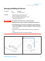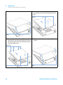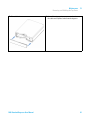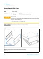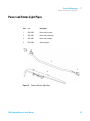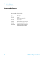
1
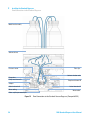
Agilent 1260 Infinity
Standard Degasser
User Manual
Agilent Technologies
Notices
© Agilent Technologies, Inc. 2006-2008,
2010-2013, 2014
No part of this manual may be reproduced
in any form or by any means (including electronic storage and retrieval or translation
into a foreign language) without prior agreement and written consent from Agilent
Technologies, Inc. as governed by United
States and international copyright laws.
Manual Part Number
G1322-90014
Edition
02/2014
Printed in Germany
Agilent Technologies
Hewlett-Packard-Strasse 8
76337 Waldbronn
This product may be used as a component of an in vitro diagnostic system if the system is registered with
the appropriate authorities and complies with the relevant regulations.
Otherwise, it is intended only for general laboratory use.
Warranty
The material contained in this document is provided “as is,” and is subject to being changed, without notice,
in future editions. Further, to the maximum extent permitted by applicable
law, Agilent disclaims all warranties,
either express or implied, with regard
to this manual and any information
contained herein, including but not
limited to the implied warranties of
merchantability and fitness for a particular purpose. Agilent shall not be
liable for errors or for incidental or
consequential damages in connection
with the furnishing, use, or performance of this document or of any
information contained herein. Should
Agilent and the user have a separate
written agreement with warranty
terms covering the material in this
document that conflict with these
terms, the warranty terms in the separate agreement shall control.
receive no greater than Restricted Rights as
defined in FAR 52.227-19(c)(1-2) (June
1987). U.S. Government users will receive
no greater than Limited Rights as defined in
FAR 52.227-14 (June 1987) or DFAR
252.227-7015 (b)(2) (November 1995), as
applicable in any technical data.
Safety Notices
CAUTION
A CAUTION notice denotes a
hazard. It calls attention to an
operating procedure, practice, or
the like that, if not correctly performed or adhered to, could
result in damage to the product
or loss of important data. Do not
proceed beyond a CAUTION
notice until the indicated conditions are fully understood and
met.
Technology Licenses
The hardware and/or software described in
this document are furnished under a license
and may be used or copied only in accordance with the terms of such license.
Restricted Rights Legend
If software is for use in the performance of a
U.S. Government prime contract or subcontract, Software is delivered and licensed as
“Commercial computer software” as
defined in DFAR 252.227-7014 (June 1995),
or as a “commercial item” as defined in FAR
2.101(a) or as “Restricted computer software” as defined in FAR 52.227-19 (June
1987) or any equivalent agency regulation
or contract clause. Use, duplication or disclosure of Software is subject to Agilent
Technologies’ standard commercial license
terms, and non-DOD Departments and
Agencies of the U.S. Government will
WA R N I N G
A WARNING notice denotes a
hazard. It calls attention to an
operating procedure, practice,
or the like that, if not correctly
performed or adhered to, could
result in personal injury or
death. Do not proceed beyond a
WARNING notice until the indicated conditions are fully understood and met.
1260 Standard Degasser User Manual
In This Guide...
In This Guide...
This manual covers the Agilent 1260 Infinity Standard Degasser (G1322A).
1 Introduction
This chapter gives an introduction to the module, the operations modes
and the module control.
2 Site Requirements and Specifications
This chapter provides information on environmental requirements, physical
and performance specifications.
3 Installing the Standard Degasser
This chapter provides information on unpacking, checking on
completeness, stack considerations and installation of the module.
4 Using the Degasser
This chapter provides information for optimized usage of the module.
5 Troubleshooting and Diagnostics
Overview about the troubleshooting and diagnostic features.
6 Maintenance
This chapter describes the maintenance of the module.
7 Parts for Maintenance
This chapter provides information on parts for maintenance.
8 Identifying Cables
This chapter provides information on cables used with the Agilent 1200
Infinity Series modules.
1260 Standard Degasser User Manual
3
In This Guide...
9 Appendix
This chapter provides additional information on safety, legal and web.
4
1260 Standard Degasser User Manual
Contents
Contents
1 Introduction
7
Introduction to the Standard Degasser
How the Electronics Work 9
2 Site Requirements and Specifications
8
13
Site Requirements 14
Physical Specifications 17
Performance Specifications 18
3 Installing the Standard Degasser
19
Unpacking the Standard Degasser 20
Optimizing the Stack Configuration 22
Installation Information on Leak and Waste Handling
Installing the Standard Degasser 29
Flow Connections to the Standard Degasser 31
Operational Hints for the Standard Degasser 35
Transporting the Standard Degasser 38
4 Using the Degasser
39
When to Use a Degasser? 40
Solvent Information 41
Prevent Blocking of Solvent Filters 47
Operation Modes of the Vacuum Degasser
5 Troubleshooting and Diagnostics
48
51
Overview of the Degasser’s Indicators
Status Indicators 53
1260 Standard Degasser User Manual
25
52
5
Contents
6 Maintenance
55
Warnings and Cautions 56
Simple Repairs - Maintenance 57
Cleaning the Instrument 58
Removing and Refitting the Top Cover 59
Assembling the Main Cover 62
Exchanging the Fuses of the Power Inline Filter
7 Parts for Maintenance
65
Cover Parts 66
Power and Status Light Pipes
Accessory Kit Contents 68
8 Identifying Cables
Cable Overview
9 Appendix
63
67
69
70
77
General Safety Information 78
The Waste Electrical and Electronic Equipment (WEEE) Directive
(2002/96/EC) 81
Radio Interference 82
Sound Emission 83
Agilent Technologies on Internet 84
6
1260 Standard Degasser User Manual
1260 Standard Degasser User Manual
1
Introduction
Introduction to the Standard Degasser
How the Electronics Work
8
9
This chapter gives an introduction to the module, the operations modes and the
module control.
Agilent Technologies
7
1
Introduction
Introduction to the Standard Degasser
Introduction to the Standard Degasser
The Agilent 1260 Infinity Standard Degasser G1322A comprises a
4- channel vacuum container, including 4 tubular plastic membranes, and a
vacuum pump. When the standard degasser is switched on, the control
circuit turns on the vacuum pump which generates a partial vacuum in
the vacuum container The pressure is meassured by a pressure sensor.
The standard degasser maintains the partial vacuum by turning on and off
the vacuum pump depending on the signal from the pressure sensor.
The LC pump draws the solvents from their bottles through the special
tubular plastic membranes of the vacuum container. As the solvents pass
through the vacuum tubes any dissolved gas in the solvents permeates
through the membranes into the vacuum container. The solvents will be
almost completely degassed when leaving the outlets of the standard
degasser.
HZchdg
8dcigda
X^gXj^i
KVXjjb
ejbe
Ejbe
)IjWjaVg
eaVhi^X
bZbWgVcZh
HdakZci
KVXjjbXdciV^cZg
Figure 1
8
Overview (only one of the four solvent channels is shown)
1260 Standard Degasser User Manual
Introduction
How the Electronics Work
1
How the Electronics Work
The standard degasser has two different normal operation modes and a
continuous mode. In operation mode 1 the standard degasser works
around a defined set point (115 Torr). Due to environmental conditions it
is possible that the standard degasser cannot reach the pre- defined set
point. Under this condition the operation mode 2 becomes active and the
vacuum pump is activated in defined time intervals (vacuum level 115 –
190 Torr). In case of a malfunction of the standard degasser (vacuum level
above 190 Torr) the instrument is turned into the error mode.
EgZhhjgZ
6bW^Zci
:ggdgA^b^i
&.%Idgg
-b^c
-b^c
DeZgVi^dcBdYZ'
&&*Idgg
DeZgVi^dcBdYZ&
i^bZ
Figure 2
Operation Modes of the Standard Degasser
The main function of the standard degasser control assembly is to control
the vacuum pump and to check the vacuum in the vacuum container.
The power section of the degasser control assembly comprises a switching
power supply that generates + 24 V from line voltage. The + 24 V is used
to drive the vacuum pump and the solenoid valve. The electronic control
circuit uses + 12 V which is generated from the + 24 V.
The pressure sensor is connected to the vacuum chamber and checks for
the correct vacuum in the system.
1260 Standard Degasser User Manual
9
1
Introduction
How the Electronics Work
The amplifier and comparator circuit determines the working range of the
vacuum that has to be built up. When the standard degasser is turned on
and the vacuum in the chamber is not within working range (above error
limit of 190 Torr), the amplifier and comparator circuit sends a signal to
the vacuum pump driver and the timers of the vacuum pump (timer 1)
and the solenoid valve (timer 2).
The vacuum pump is turned on immediately while the solenoid valve
closing is delayed by 15 s. This time delay allows the vacuum pump to
start without load before it is connected to the vacuum chamber. The
status indicator turns yellow when the pump is activated. The status lamp
is turned off as soon as the vacuum is below the error limit.
When the vacuum in the chamber reaches its operation mode 1
(approximately 115 Torr) the amplifier and comparator circuit turns off
the solenoid valve and the vacuum pump is turned off by a timer with a
delay of 15 s.
As soon as the pressure sensor detects that the limit of the operation
mode 1 has been exceeded (e.g. when dissolved gas from the solvent
diffused into the vacuum chamber) the vacuum pump is started again as
described before.
The pressure signal is available at the auxiliary output. It allows to
monitor the vacuum system. The upper limit of operation mode 1 is
600 mV. Values below 600 mV on the pressure output indicate sufficient
vacuum in the chamber. If the 600 mV are exceeded the vacuum pump
will be started to keep the vacuum with in its working limit.
The amplifier and comparator circuit also activates the timer 3 when the
vacuum in the vacuum chambers is below operation mode 1. The timer 3
is reset when operation mode 1 is reached within a maximum of 8 min. If
operation mode 1 is not reached and the time (8 min) of timer 3 elapsed,
the timer mode (operation mode 2) is activated. In this mode the vacuum
pump is automatically turned on every 2 min for a time frame of 30 s.
Timers 1 and 2 are activated as described earlier.
The error monitor continuously checks the error limit of the degasser
(190 Torr). If the error limit is exceeded (for example, leak in chamber),
the error timer is activated and the yellow status indicator lamp is turned
on. The vacuum pump is turned on continuously. If the vacuum pump
cannot reach either of its two operation modes within 8 min (error timer
limit) the error driver is activated. The error driver will deactivate the
vacuum pump and solenoid valve. The status lamp turns red and the error
output on the remote connector will be activated.
10
1260 Standard Degasser User Manual
1
Introduction
How the Electronics Work
The error output at the remote connector provides a contact closure
(potential free open collector maximum load 35 VDC/50 mA) as long as
the error condition is active. The error condition is set (closed) when the
status light shows the error condition (red).
The continuous mode overwrites all other operation modes of the
degasser. When activated (switch SW1 on the electronic board or via the
auxiliary cable) the vacuum pump is forced into continuous mode and is
turned on as long as the degasser is switched ON.
1260 Standard Degasser User Manual
11
1
12
Introduction
How the Electronics Work
1260 Standard Degasser User Manual
1260 Standard Degasser User Manual
2
Site Requirements and Specifications
Site Requirements
14
Physical Specifications
17
Performance Specifications
18
This chapter provides information on environmental requirements, physical and
performance specifications.
Agilent Technologies
13
2
Site Requirements and Specifications
Site Requirements
Site Requirements
A suitable environment is important to ensure optimal performance of the
instrument.
Power Considerations
The module power supply has wide ranging capability. It accepts any line
voltage in the range described in Table 1 on page 17. Consequently there
is no voltage selector in the rear of the module.
WA R N I N G
Hazard of electrical shock or damage of your instrumentation
can result, if the devices are connected to a line voltage higher than specified.
➔ Connect your instrument to the specified line voltage only.
WA R N I N G
The module is partially energized when switched off, as long as the power cord is
plugged in.
Repair work at the module can lead to personal injuries, e.g. electrical shock, when
the cover is opened and the module is connected to power.
➔ Always unplug the power cable before opening the cover.
➔ Do not connect the power cable to the instrument while the covers are removed.
CAUTION
Inaccessible power plug.
In case of emergency it must be possible to disconnect the instrument from the power
line at any time.
➔ Make sure the power connector of the instrument can be easily reached and
unplugged.
➔ Provide sufficient space behind the power socket of the instrument to unplug the
cable.
14
1260 Standard Degasser User Manual
2
Site Requirements and Specifications
Site Requirements
Power Cords
Different power cords are offered as options with the module. The female
end of all power cords is identical. It plugs into the power- input socket at
the rear. The male end of each power cord is different and designed to
match the wall socket of a particular country or region.
WA R N I N G
Absence of ground connection or use of unspecified power cord
The absence of ground connection or the use of unspecified power cord can lead to
electric shock or short circuit.
➔ Never operate your instrumentation from a power outlet that has no ground
connection.
➔ Never use a power cord other than the Agilent Technologies power cord designed
for your region.
WA R N I N G
Use of unsupplied cables
Using cables not supplied by Agilent Technologies can lead to damage of the
electronic components or personal injury.
➔ Never use cables other than the ones supplied by Agilent Technologies to ensure
proper functionality and compliance with safety or EMC regulations.
WA R N I N G
Unintended use of supplied power cords
Using power cords for unintended purposes can lead to personal injury or damage of
electronic equipment.
➔ Never use the power cords that Agilent Technologies supplies with this instrument
for any other equipment.
1260 Standard Degasser User Manual
15
2
Site Requirements and Specifications
Site Requirements
Bench Space
The module dimensions and weight (see Table 1 on page 17) allow you to
place the module on almost any desk or laboratory bench. It needs an
additional 2.5 cm (1.0 inches) of space on either side and approximately
8 cm (3.1 inches) in the rear for air circulation and electric connections.
If the bench shall carry a complete HPLC system, make sure that the
bench is designed to bear the weight of all modules.
The module should be operated in a horizontal position.
Condensation
CAUTION
Condensation within the module
Condensation will damage the system electronics.
➔ Do not store, ship or use your module under conditions where temperature
fluctuations could cause condensation within the module.
➔ If your module was shipped in cold weather, leave it in its box and allow it to warm
slowly to room temperature to avoid condensation.
16
1260 Standard Degasser User Manual
2
Site Requirements and Specifications
Physical Specifications
Physical Specifications
Table 1
Type
Specification
Weight
7 kg (16 lbs)
Dimensions (height ×
width × depth)
80 x 345 x 435 mm (3.1 x 13.5 x 17 inches)
Line voltage
100 – 240 V~, ± 10 %
Line frequency
50 or 60 Hz, ± 5 %
Power consumption
30VA/30W/210BTU
Ambient operating
temperature
0 – 55 °C (32 – 131 °F) 1
Ambient non-operating
temperature
-40 – 70 °C (-40 – 158 °F)
Humidity
< 95 % r.h. at 40 °C (104 °F)
Operating altitude
Up to 2000 m (6562 ft)
Non-operating altitude
Up to 4600 m (15091 ft)
For storing the module
Safety standards: IEC, CSA,
UL
Installation category II, Pollution degree 2
For indoor use only.
1
NOTE
Physical Specifications
Comments
Wide-ranging
capability
Maximum
Non-condensing
This temperature range represents the technical specifications for this instrument. The temperatures mentioned may not be suitable for all applications and all types of solvent.
The Agilent 1260 Infinity degasser has been tested for evaporation of solvents into the
atmosphere by an independent institute with approved methods. The tests were performed
with Methanol (BIA Nr. 7810) and Acetonitrile (NIOSH, Nr. 1606). Evaporation of these
solvents into the atmosphere when operating the degasser was below the limits of
detection.
1260 Standard Degasser User Manual
17
2
Site Requirements and Specifications
Performance Specifications
Performance Specifications
Table 2
18
Performance Specifications Agilent 1260 Infinity Standard Degasser
Type
Specification
Maximum flow rate
10 mL/min per channel
Number of channels
4
Internal volume per channel
Typically 12 mL per channel
Materials in contact with solvent
PTFE, PEEK
pH range
1 – 14
Analog output (AUX)
For pressure monitoring, range 0 – 3 V
1260 Standard Degasser User Manual
1260 Standard Degasser User Manual
3
Installing the Standard Degasser
Unpacking the Standard Degasser
Damaged Packaging 20
Delivery Checklist 20
Accessory Kit Contents 21
20
Optimizing the Stack Configuration
One Stack Configuration 23
22
Installation Information on Leak and Waste Handling
Installing the Standard Degasser
25
29
Flow Connections to the Standard Degasser
31
Operational Hints for the Standard Degasser
Priming the Degasser 35
Priming with a Syringe 35
Priming with the Pump 37
35
Transporting the Standard Degasser
38
This chapter provides information on unpacking, checking on completeness,
stack considerations and installation of the module.
Agilent Technologies
19
3
Installing the Standard Degasser
Unpacking the Standard Degasser
Unpacking the Standard Degasser
Damaged Packaging
If the delivery packaging shows signs of external damage, please call your
Agilent Technologies sales and service office immediately. Inform your
service representative that the instrument may have been damaged during
shipment.
CAUTION
"Defective on arrival" problems
If there are signs of damage, please do not attempt to install the module. Inspection by
Agilent is required to evaluate if the instrument is in good condition or damaged.
➔ Notify your Agilent sales and service office about the damage.
➔ An Agilent service representative will inspect the instrument at your site and
initiate appropriate actions.
Delivery Checklist
Ensure all parts and materials have been delivered with the degasser. The
delivery checklist is shown below.
To aid in parts identification, please see “Parts for Maintenance” on
page 65
Please report missing or damaged parts to your local Agilent Technologies
Sales and Service Office.
Table 3
20
Standard Degasser Delivery Checklist
Description
Quantity
Standard degasser
1
Power cable
1
Remote cable
1
Auxiliary cable
As ordered
User Manual on Documentation CD (part of the shipment - not module
specific)
1 per order
Accessory kit (“Accessory Kit Contents” on page 21)
1
1260 Standard Degasser User Manual
Installing the Standard Degasser
Unpacking the Standard Degasser
3
Accessory Kit Contents
Accessory Kit (G1322- 68705)
p/n
Description
5062-8534
Syringe
Reorder number (pack of 10)
9301-1337
Syringe adapter
0100-1710
Mounting Tool for Tubing Connections
5062-2463
Corrugated tubing, PP, 6.5 mm id, 5 m
G1322-67300
Kit of 4 solvent tubes including labels
for connection degasser to MCGV
1260 Standard Degasser User Manual
21
3
Installing the Standard Degasser
Optimizing the Stack Configuration
Optimizing the Stack Configuration
If your module is part of a complete Agilent Liquid Chromatograph, you
can ensure optimum performance by installing the following
configurations. These configurations optimize the system flow path,
ensuring minimum delay volume.
22
1260 Standard Degasser User Manual
Installing the Standard Degasser
Optimizing the Stack Configuration
3
One Stack Configuration
Ensure optimum performance by installing the modules of the Agilent
1260 Infinity LC System in the following configuration (See Figure 3 on
page 23 and Figure 4 on page 24). This configuration optimizes the flow
path for minimum delay volume and minimizes the bench space required.
HdakZciXVW^cZi
KVXjjbYZ\VhhZg
Ejbe
>chiVciE^adi
6jidhVbeaZg
8dajbcXdbeVgibZci
9ZiZXidg
Figure 3
Recommended Stack Configuration for 1260 Infinity (Front View)
1260 Standard Degasser User Manual
23
3
Installing the Standard Degasser
Optimizing the Stack Configuration
GZbdiZXVWaZ
86C7jhXVWaZid
>chiVciE^adi
68edlZg
86C7jhXVWaZ
6cVad\YZiZXidg
h^\cVa
&dg'djiejih
eZgYZiZXidg
A6CidA88]ZbHiVi^dc
adXVi^dcYZeZcYhdcYZiZXidg
Figure 4
24
Recommended Stack Configuration for 1260 Infinity (Rear View)
1260 Standard Degasser User Manual
Installing the Standard Degasser
Installation Information on Leak and Waste Handling
3
Installation Information on Leak and Waste Handling
The Agilent 1200 Infinity Series has been designed for safe leak and waste
handling. It is important that all security concepts are understood and
instructions are carefully followed.
WA R N I N G
Toxic, flammable and hazardous solvents, samples and reagents
The handling of solvents, samples and reagents can hold health and safety risks.
➔ When working with these substances observe appropriate safety procedures (for
example by wearing goggles, safety gloves and protective clothing) as described in
the material handling and safety data sheet supplied by the vendor, and follow good
laboratory practice.
➔ The volume of substances should be reduced to the minimum required for the
analysis.
➔ Never exceed the maximal permissible volume of solvents (6 L) in the solvent
cabinet.
➔ Do not use bottles that exceed the maximum permissible volume as specified in the
usage guideline for the Agilent 1200 Infinity Series Solvent Cabinets.
➔ Arrange the bottles as specified in the usage guideline for the solvent cabinet.
➔ A printed copy of the guideline has been shipped with the solvent cabinet,
electronic copies are available on the Internet.
NOTE
Recommendations for Solvent Cabinet
For details, see the usage guideline for the Agilent 1200 Infinity Series Solvent Cabinets.
1260 Standard Degasser User Manual
25
3
Installing the Standard Degasser
Installation Information on Leak and Waste Handling
&
6
'
7
8
(
)
*
,
+
,
Figure 5
26
Leak and waste handling (overview - typical stack configuration as an
example)
1260 Standard Degasser User Manual
3
Installing the Standard Degasser
Installation Information on Leak and Waste Handling
1
Solvent cabinet
2
Leak pan
3
Leak pan's outlet port (A), leak funnel (B) and corrugated waste tube (C)
4
Waste tube of the sampler’s needle wash
5
Condense drain outlet of the autosampler cooler
6
Waste tube of the purge valve
7
Waste tube
1 Stack the modules according to the adequate stack configuration.
The leak pan outlet of the upper module must be vertically positioned
above the leak tray of the lower module, see Figure 5 on page 26.
2 Connect data and power cables to the modules, see section Installing
the Module below.
3 Connect capillaries and tubes to the modules, see section Flow
Connections to the module below or the relevant system manual.
WA R N I N G
Toxic, flammable and hazardous solvents, samples and reagents
➔ Keep solvent path free from blockages.
➔ Keep the flow path closed (in case the pump in the system is equipped with a
passive inlet valve, solvent may leak out due to hydrostatic pressure, even if your
instrument is off).
➔ Avoid loops.
➔ Tubes must not sag.
➔ Do not bend tubes.
➔ Do not immerse tube end in waste liquid.
➔ Do not intubate tubes in other tubes.
➔ For correct tubing follow instructions on label attached to the module.
1260 Standard Degasser User Manual
27
3
Installing the Standard Degasser
Installation Information on Leak and Waste Handling
Figure 6
28
Warning label (illustration for correct waste tubing)
1260 Standard Degasser User Manual
Installing the Standard Degasser
Installing the Standard Degasser
3
Installing the Standard Degasser
Parts required
#
Description
1
Standard degasser
1
Power cord
1
Interface cable as ordered
See “Cable Overview” on page 70.
Preparations
CAUTION
•
•
•
Locate bench space
Provide power connections
Unpack the module
"Defective on arrival" problems
If there are signs of damage, please do not attempt to install the module. Inspection by
Agilent is required to evaluate if the instrument is in good condition or damaged.
➔ Notify your Agilent sales and service office about the damage.
➔ An Agilent service representative will inspect the instrument at your site and
initiate appropriate actions.
1 Place the module on the bench in a horizontal position.
2 Ensure the power switch on the front of the module is OFF (switch stands
out).
3 Connect the power cable to the power connector at the rear of the module.
4 Connect the interface cable to the degasser. The interface cable (remote
cable) is a one way connection to send a not- ready signal from the
degasser to the other modules to shut down the whole system after an
error condition of the degasser.
NOTE
In an Agilent 1260 Infinity system, the individual modules are connected through a CAN
cable. The Agilent 1260 Infinity Standard Degasser is an exception. The standard degasser
can be connected via the APG remote connector to the other modules of the stack. The
AUX output allows to monitor the vacuum pressure in the degasser chamber. A G4208A
Instant Pilot can be connected to the CAN bus at any of the modules in the system except
for the degasser. The chromatography data system can be connected to the system through
a LAN cable at any of the modules (except for the degasser), preferably at the detector. For
more information about connecting the Instant Pilot or a data system refer to the respective
user manual.
1260 Standard Degasser User Manual
29
3
Installing the Standard Degasser
Installing the Standard Degasser
EdlZghdX`Zi
;jhZ]daYZg
Figure 7
Rear of the Standard Degasser
Figure 8
Front of the Standard Degasser
HiVijh^cY^XVidg
EdlZghl^iX]
LVhiZdjiaZi
HZg^VacjbWZg
5 Press in the power switch to turn on the vacuum degasser.
NOTE
30
The power switch stays pressed in and a green indicator lamp in the power switch is ON
when the vacuum degasser is turned ON. When the line power switch stands out and the
green light is OF, the vacuum degasser is turned OFF.
1260 Standard Degasser User Manual
Installing the Standard Degasser
Flow Connections to the Standard Degasser
3
Flow Connections to the Standard Degasser
Parts required
Preparations
WA R N I N G
#
Description
1
Solvent cabinet including solvent bottles (filled with solvent) and bottle head assemblies
1
Standard degasser
1
Solvent outlet tubes
1
Syringe with adapter
•
Install the degasser
Toxic, flammable and hazardous solvents, samples and reagents
The handling of solvents, samples and reagents can hold health and safety risks.
➔ When working with these substances observe appropriate safety procedures (for
example by wearing goggles, safety gloves and protective clothing) as described in
the material handling and safety data sheet supplied by the vendor, and follow good
laboratory practice.
➔ The volume of substances should be reduced to the minimum required for the
analysis.
➔ Do not operate the instrument in an explosive atmosphere.
1 Place solvent cabinet with the bottle(s) on top of the degasser.
2 Remove the front cover by pressing the snap fasteners on both sides.
Figure 9
Removing the Front Cover
1260 Standard Degasser User Manual
31
3
Installing the Standard Degasser
Flow Connections to the Standard Degasser
3 If the degasser is not used with an Agilent 1260 Infinity pump, connect
the waste tube from the accessory kit to the waste outlet and place into
your waste system.
4 Put the bottle head assemblies into solvent bottles containing your
mobile phase.
5 Connect the solvent tubes from the bottle head assemblies to the inlet
connectors A to D (typically the left connection of the channel) of the
degasser. Use the mounting tool shown in Figure 10 on page 32 to fix
the tube screw. Fix the tubes in the clips of the degasser.
Figure 10
Mounting Tool
6 Connect the outlet tubes to the output ports (typically right connection
of the channel) of the degasser.
7 Prime the degasser before first use (see “Priming the Degasser” on
page 35).
NOTE
32
Atmospheric gases can diffuse through the tubing and dissolve in the mobile phase
solvents. For best chromatographic results, keep the length of tubing between the degasser
and the pump as short as possible.
1260 Standard Degasser User Manual
Installing the Standard Degasser
Flow Connections to the Standard Degasser
3
7diiaZ]ZVYVhhZbWan
HdakZciXVW^cZi
EgZhhjgZhZchdg
IjWZXa^e
HiVi^Xb^mZg
Ejg\ZkVakZ
Ejbe]ZVYX]VccZa7
Ejbe]ZVYX]VccZa6
6YVeiZg
6Xi^kZ^caZikVakZ6
6Xi^kZ^caZikVakZ7
LVhiZijW^c\
DjiaZiXVe^aaVgnidVjidhVbeaZg
Figure 11
LVhiZdjiaZi
Flow Connections to the Standard Vacuum Degasser (Pump without SSV)
1260 Standard Degasser User Manual
33
3
Installing the Standard Degasser
Flow Connections to the Standard Degasser
7diiaZ]ZVYVhhZbWan
HdakZciXVW^cZi
IjWZXa^eh
EgZhhjgZhZchdg
HdakZcihZaZXi^dckVakZ
Ejg\ZkVakZ
Ejbe]ZVYX]VccZa6
Ejbe]ZVYX]VccZa7
6YVeiZg
6Xi^kZ^caZikVakZ7
6Xi^kZ^caZikVakZ6
LVhiZijW^c\
LVhiZdjiaZi
DjiaZiXVe^aaVgnidVjidhVbeaZg
Figure 12
34
Flow Connections to the Standard Vacuum Degasser (Pump with SSV)
1260 Standard Degasser User Manual
3
Installing the Standard Degasser
Operational Hints for the Standard Degasser
Operational Hints for the Standard Degasser
Priming the Degasser
The standard degasser can be primed either by drawing solvent through
the degasser with a syringe or by pumping with the connected pump.
Priming the standard degasser with a syringe is recommended, when:
• standard degasser is used for the first time, or vacuum tubes are empty,
or
• changing to solvents that are immiscible with the solvent currently in
the vacuum tubes.
Priming the standard degasser by using the pump at high flow rate (3 –
5 mL/min) is recommended, when:
• pumping system was turned off for a length of time (for example,
overnight) and if volatile solvent mixtures are used, or
• if solvents have been changed.
Priming with a Syringe
Before using a new degasser or new tubings for the first time:
WA R N I N G
Toxic, flammable and hazardous solvents, samples and reagents
The handling of solvents, samples and reagents can hold health and safety risks.
➔ When working with these substances observe appropriate safety procedures (for
example by wearing goggles, safety gloves and protective clothing) as described in
the material handling and safety data sheet supplied by the vendor, and follow good
laboratory practice.
➔ The volume of substances should be reduced to the minimum required for the
analysis.
➔ Do not operate the instrument in an explosive atmosphere.
1260 Standard Degasser User Manual
35
3
Installing the Standard Degasser
Operational Hints for the Standard Degasser
1 Prime all tubings with at least 30 ml of iso- propanol no matter whether
the channels will be used with organic mobile phase or with water.
If you are changing to a solvent that is immiscible with the solvent
currently in the tubing continue as follows:
2 Replace the current solvent with iso- propanol, if current solvent is
organic or with water, if current solvent is an inorganic buffer or
contains salt.
3 Disconnect solvent outlet tube of the channel that is supposed to be
primed from your pump.
4 Connect syringe adapter to solvent outlet tube.
5 Push syringe adapter onto syringe.
6 Pull syringe plunger to draw at least 30 ml of solvent through degasser
and tubing.
7 Replace the priming solvent with the new solvent of your choice.
8 Pull syringe plunger to draw at least 30 ml of solvent through degasser
and tubing.
9 Disconnect syringe adapter from solvent tube.
10 Connect solvent tube to your pump.
11 Repeat step 3 on page 36 to step 10 on page 36 for the other solvent
channels.
36
NOTE
When priming the standard degasser with a syringe the solvent is drawn through the
degasser tubes very quickly. The solvent at the degasser outlet will therefore not be fully
degassed. Pump for approximately 10 min with your selected flow rate before starting any
application. This will allow the standard degasser to properly degas the solvent in the
degasser tubes.
NOTE
The pump should never be used for priming empty tubings (never let the pump run dry). Use
the syringe to draw enough solvent for completely filling the tubings to the pump inlet
before continueing to prime with the pump.
1260 Standard Degasser User Manual
Installing the Standard Degasser
Operational Hints for the Standard Degasser
3
Priming with the Pump
When the pumping system has been turned off for a certain time (for
example, overnight) oxygen will rediffuse into the solvent channels
between the standard degasser and the pump. Solvents containing volatile
ingredients will slightly lose these, if left in the degasser without flow for
a prolonged period of time. Therefore priming of the standard degasser
and the pumping system is required before starting an application.
1 Open the purge valve of your pump and set flow rate to 5 ml/min.
2 Flush the standard degasser and all tubes with at least 30 mL of
solvent.
3 Set flow to required value of your application and close the purge
valve.
4 Pump for approximately 10 minutes before starting your application.
5 Repeat step 1 on page 37 through step 4 on page 37 with other
channels, where needed.
1260 Standard Degasser User Manual
37
3
Installing the Standard Degasser
Transporting the Standard Degasser
Transporting the Standard Degasser
WA R N I N G
Solvents leaking out
Solvents remaining in the solvent channels may leak out during transport. This can
possibly cause personal damage.
➔ Drain any remaining solvents from the degassing channels before transporting the
degasser.
1 Disconnect the solvent tubes from solvent inlets from front panel.
2 Disconnect one of the solvent tubes from your pump.
3 Connect syringe adapter to solvent tube of this solvent channel.
4 Push syringe adapter onto syringe.
5 Pull syringe plunger to draw solvent out of degasser and tubing.
Continue to draw solvent into syringe until the solvent channel is
completely empty.
6 Repeat step 2 on page 38 through step 5 on page 38 for the remaining
solvent channels.
38
1260 Standard Degasser User Manual
1260 Standard Degasser User Manual
4
Using the Degasser
When to Use a Degasser?
40
Solvent Information 41
Material Information 41
Prevent Blocking of Solvent Filters
47
Operation Modes of the Vacuum Degasser 48
Normal Operation Mode 1 49
Normal Operation Mode 2 (Timing Mode) 49
Continuous Mode 50
Error Mode 50
This chapter provides information for optimized usage of the module.
Agilent Technologies
39
4
Using the Degasser
When to Use a Degasser?
When to Use a Degasser?
WA R N I N G
Unspecified Conditions
Operating the instrumentation under conditions other than its intended use might
result in a potential safety hazard or might damage the instrumentation.
➔ Never operate your instrumentation under conditions other than those specified by
the vendor.
Pumps that mix the solvent on the low pressure side need degassing and
must be equipped with a degasser or alternative degassing systems (for
example, helium). Isocratic pumps and high- pressure mixing pumps do not
always require degassing. However for the following conditions the
standard degasser is also recommended for an isocratic or a high pressure
mixing pump:
• if your detector is used with maximum sensitivity in the low UV
wavelength range,
• if your application requires optimum injection precision, or
• if your application requires highest retention time reproducibility
(mandatory at flow rates below 0.5 mL/min),
• if your sample or detection is sensitive to dissolved oxygen in the
mobile phase (degradation).
Generally a degasser should be used when negative effects due to
dissolved gas in the mobile phase exceed the limits that are acceptable for
the user. Negative effects that can be caused by dissolved gas are:
• Unstable flow due to unstable pumping conditions. This may result in a
high ripple (unstable pressure at constant flow and with constant
mobile phase composition) or high standard deviations of peak
retention times and peak areas especially at low flow rates.
• Baseline noise on detectors that are sensitive to changes in the
refractive index (e.g. RI detector or UV detector in the low UV range,
both at maximum sensitivity).
• Sample degradation.
• Fluorescence quenching due to dissolved oxygen.
• Baseline drift in electrochemical detectors due to dissolved oxygen
especially in reduction mode.
40
1260 Standard Degasser User Manual
4
Using the Degasser
Solvent Information
Solvent Information
Observe the following recommendations on the use of solvents.
• Follow recommendations for avoiding the growth of algae, see pump
manuals.
• Small particles can permanently block capillaries and valves. Therefore,
always filter solvents through 0.4 µm filters.
• Avoid or minimize the use of solvents that may corrode parts in the
flow path. Consider specifications for the pH range given for different
materials like flow cells, valve materials etc. and recommendations in
subsequent sections.
Material Information
Material in Flow Path
Following materials are used in the flow path of this module:
Table 4
Material in flow path
Part
Material
Internal tubings
PTFE
Inlets
PEEK
Tubings
FEP
Fittings
ETFE
1260 Standard Degasser User Manual
41
4
Using the Degasser
Solvent Information
Material Information
Materials in the flow path are carefully selected based on Agilent’s
experiences in developing highest quality instruments for HPLC analysis
over several decades. These materials exhibit excellent robustness under
typical HPLC conditions. For any special conditions, please consult the
material information section or contact Agilent.
Disclaimer
Subsequent data were collected from external resources and are meant as
a reference. Agilent cannot guarantee the correctness and completeness of
such information. Data is based on compatibility libraries, which are not
specific for estimating the long- term life time under specific but highly
variable conditions of UHPLC systems, solvents, solvent mixtures and
samples. Information can also not be generalized due to catalytic effects of
impurities like metal ions, complexing agents, oxygen etc. Apart from pure
chemical corrosion, other effects like electro corrosion, electrostatic
charging (especially for non- conductive organic solvents), swelling of
polymer parts etc. need to be considered. Most data available refers to
room temperature (typically 20 – 25 °C, 68 – 77 °F). If corrosion is
possible, it usually accelerates at higher temperatures. If in doubt, please
consult technical literature on chemical compatibility of materials.
PEEK
PEEK (Polyether- Ether Ketones) combines excellent properties regarding
biocompatibility, chemical resistance, mechanical and thermal stability.
PEEK is therefore the material of choice for UHPLC and biochemical
instrumentation.
It is stable in a wide pH range, and inert to many common solvents.
There is still a number of known incompatibilities with chemicals such as
chloroform, methylene chloride, THF, DMSO, strong acids (nitric acid >
10 %, sulphuric acid > 10 %, sulfonic acids, trichloroacetic acid), halogenes
or aequous halogene solutions, phenol and derivatives (cresols, salicylic
acid etc.).
42
1260 Standard Degasser User Manual
4
Using the Degasser
Solvent Information
Polyimide
Agilent uses semi- crystalline polyimide for rotor seals in valves and needle
seats in autosamplers. One supplier of polyimide is DuPont, which brands
polyimide as Vespel, which is also used by Agilent.
Polyimide is stable in a pH range between 1 and 10 and in most organic
solvents. It is incompatible with concentrated mineral acids (e.g. sulphuric
acid), glacial acetic acid, DMSO and THF. It is also degraded by
nucleophilic substances like ammonia (e.g. ammonium salts in basic
conditions) or acetates.
Polyethylene (PE)
Agilent uses UHMW (ultra- high molecular weight)- PE/PTFE blends for
yellow piston and wash seals, which are used in 1290 Infinity pumps and
for normal phase applications in 1260 Infinity pumps.
Polyethylene has a good stability for most common inorganic solvents
including acids and bases in a pH range of 1 to 12.5. It is compatible to
many organic solvents used in chromatographic systems like methanol,
acetonitrile and isopropanol. It has limited stability with aliphatic,
aromatic and halogenated hydrocarbons, THF, phenol and derivatives,
concentrated acids and bases. For normal phase applications, the
maximum pressure should be limited to 200 bar.
Tantalum (Ta)
Tantalum is inert to most common HPLC solvents and almost all acids
except fluoric acid and acids with free sulfur trioxide. It can be corroded
by strong bases (e.g. hydroxide solutions > 10 %, diethylamine). It is not
recommended for the use with fluoric acid and fluorides.
1260 Standard Degasser User Manual
43
4
Using the Degasser
Solvent Information
Stainless Steel (ST)
Stainless steel is inert against many common solvents. It is stable in the
presence of acids and bases in a pH range of 1 to 12.5. It can be corroded
by acids below pH 2.3. It can also corrode in following solvents:
• Solutions of alkali halides, their respective acids (for example, lithium
iodide, potassium chloride, and so on) and aqueous solutions of
halogens.
• High concentrations of inorganic acids like nitric acid, sulfuric acid and
organic solvents especially at higher temperatures (replace, if your
chromatography method allows, by phosphoric acid or phosphate buffer
which are less corrosive against stainless steel).
• Halogenated solvents or mixtures which form radicals and/or acids, for
example:
2 CHCl3 + O2→ 2 COCl2 + 2 HCl
This reaction, in which stainless steel probably acts as a catalyst,
occurs quickly with dried chloroform if the drying process removes the
stabilizing alcohol.
• Chromatographic grade ethers, which can contain peroxides (for
example, THF, dioxane, di- isopropylether). Such ethers should be
filtered through dry aluminium oxide which adsorbs the peroxides.
• Solutions of organic acids (acetic acid, formic acid, and so on) in
organic solvents. For example, a 1 % solution of acetic acid in methanol
will attack steel.
• Solutions containing strong complexing agents (for example, EDTA,
ethylene diamine tetra- acetic acid).
• Mixtures of carbon tetrachloride with 2- propanol or THF.
Diamond-Like Carbon (DLC)
Diamond- Like Carbon is inert to almost all common acids, bases and
solvents. There are no documented incompatibilities for HPLC applications.
44
1260 Standard Degasser User Manual
Using the Degasser
Solvent Information
4
Fused silica and Quartz (SiO2)
Fused silica is used in 1290 Infinity Flow Cells and capillaries. Quartz is
used for classical flow cell windows. It is inert against all common
solvents and acids except hydrofluoric acid and acidic solvents containing
fluorides. It is corroded by strong bases and should not be used above pH
12 at room temperature. The corrosion of flow cell windows can negatively
affect measurement results. For a pH greater than 12, the use of flow cells
with sapphire windows is recommended.
Gold
Gold is inert to all common HPLC solvents, acids and bases within the
specified pH range. It can be corroded by complexing cyanides and
concentrated acids like aqua regia.
Zirconium Oxide (ZrO2)
Zirconium Oxide is inert to almost all common acids, bases and solvents.
There are no documented incompatibilities for HPLC applications.
Platinum/Iridium
Platinum/Iridium is inert to almost all common acids, bases and solvents.
There are no documented incompatibilities for HPLC applications.
1260 Standard Degasser User Manual
45
4
Using the Degasser
Solvent Information
Fluorinated polymers (PTFE, PFA, FEP, FFKM)
Fluorinated polymers like PTFE (polytetrafluorethylene), PFA
(perfluoroalkoxy) and FEP (fluorinated ethylene propylene) are inert to
almost all common acids, bases, and solvents. FFKM is perfluorinated
rubber, which is also resistant to most chemicals. As an elastomer, it may
swell in some organic solvents like halogenated hydrocarbons.
TFE/PDD copolymer tubings, which are used in all Agilent degassers
except G1322A, are not compatible with fluorinated solvents like Freon,
Fluorinert, or Vertrel. They have limited life time in the presence of
Hexafluoroisopropanol (HFIP). To ensure the longest possible life with
HFIP, it is best to dedicate a particular chamber to this solvent, not to
switch solvents, and not to let dry out the chamber. For optimizing the life
of the pressure sensor, do not leave HFIP in the chamber when the unit is
off.
Sapphire, Ruby and Al2O3-based ceramics
Sapphire, ruby and ceramics based on aluminum oxide Al2O3 are inert to
almost all common acids, bases and solvents. There are no documented
incompatibilities for HPLC applications.
46
1260 Standard Degasser User Manual
4
Using the Degasser
Prevent Blocking of Solvent Filters
Prevent Blocking of Solvent Filters
Contaminated solvents or algae growth in the solvent bottle will reduce
the lifetime of the solvent filter and will influence the performance of the
pump. This is especially true for aqueous solvents or phosphate buffers
(pH 4 – 7). The following suggestions will prolong lifetime of the solvent
filter and will maintain the performance of the pump.
• Use sterile, if possible amber solvent bottles to slow down algae growth.
• Filter solvents through filters or membranes that remove algae.
• Exchange solvents every two days or refilter.
• If the application permits add 0.0001 – 0.001 M sodium azide to the
solvent.
• Place a layer of argon on top of your solvent.
• Avoid exposure of the solvent bottles to direct sunlight.
Prevent Blocking of Solvent Filters
The solvent filters are on the low- pressure side of the pumping system. A
blocked filter therefore does not affect the pressure readings of the pump.
The pressure readings cannot be used to indetify blocked filters. If the
solvent cabinet is placed on top of the standard degasser the filter
condition can be checked in the following way:
Remove the tubing at the inlet port of the standard degasser. If the filter
is in good condition the solvent will freely drip out of the solvent tube
(due to hydrostatic pressure). If the solvent filter is partly blocked no
solvent or only very little solvent will drip out of the solvent tube.
Cleaning the Solvent Filters
• Remove the blocked solvent filter from the bottle- head assembly and
place it in a beaker with concentrated nitric acid (35 %) for one hour.
• Thoroughly flush the filter with bidistilled water (remove all nitric
acid).
• Replace the filter.
NOTE
Never use the system without solvent filter installed.
1260 Standard Degasser User Manual
47
4
Using the Degasser
Operation Modes of the Vacuum Degasser
Operation Modes of the Vacuum Degasser
The vacuum degasser allows various operation modes. Operation mode 1
and 2 are the normal operation modes of the degasser:
• In operation mode 1 the vacuum degasser works at 115 Torr.
• In operation mode 2 the vacuum degasser works in the range between
115 to 190 Torr.
• The continuous mode can be selected for highest degassing efficiency of
the degasser. In this mode the vacuum level is below 115 Torr.
• The error mode is activated in case the degasser cannot achieve a
vacuum level of 190 Torr.
(1 Torr = 1.33x10- 3 bar)
Table 5
Operation Modes of the Standard Degasser
Operation Mode 1
Operation Mode 2
Continuous Mode
Error Mode
Pressure range [Torr]
115
115 – 190
Below 115
Above 190
DC Voltage Readings
[mV] (rough values)
Lower limit: 590 – 600
Upper Limit: 600 – 610
600 – 800
Below 600
Above 800
Operation mode
Pump switched on
and off at upper and
lower limit during
operation
Pump switched on
every 2 min for 30 s
Pump permantly
running
8 min of continuous
pumping before
shutdown
Status Indicator
OFF - below 800 mV
YELLOW - above
800 mV
OFF - below 800 mV
YELLOW - above
800 mV
OFF - below 800 mV
YELLOW - above
800 mV
YELLOW
Failure Actions
Switch to Operation
Mode 2
Switch to Error Mode
Switch to Error Mode
Shut down module,
switch status
indicator to RED
48
NOTE
The voltage readings given for the various modes are approximate values. All values are set
in the factory according to the vacuum level. Depending on the vacuum sensor batch
variations this will result in different voltage readings. Regardless of the readings of the
various stages no adjustment should be performed on the degasser electronics.
NOTE
See service manual (troubleshooting and diagnostics) for setting up test meter connections
to the degasser for reading the pressure sensor output.
1260 Standard Degasser User Manual
Using the Degasser
Operation Modes of the Vacuum Degasser
4
Normal Operation Mode 1
When the degasser is turned ON, the vacuum pump runs and is connected
to ambient through the solenoid valve. The solenoid valve activates about
15 seconds after turning ON the degasser (you can hear it click). The
vacuum pump then begins to pull a vacuum on the vacuum chamber. The
voltage measurements begin to decrease rapidly. The yellow status LED
turns off when the vacuum level reaches 190 Torr (DC voltage readings
around 800 mV). The normal operation mode vacuum level (115 Torr) is
achieved when the DC voltage measures approximately 590 to 600 mV.
After achieving the normal operation mode vacuum level, the solenoid
valve turns off. The vacuum pump continues to run for a few seconds,
then it turns OFF. When the DC voltage measurement rises back to
approximately 600 to 610 mV, the turn on process begins again. If the
vacuum level of normal operation mode one cannot be achieved within
8 minutes the instrument turns into normal operation mode 2.
Normal Operation Mode 2 (Timing Mode)
Under certain operational conditions (large amount of dissolved gas in
mobile phase, high flow rates) the 115 Torr trigger level for operation
mode 1 cannot be reached. The standard degasser automatically turns into
operation mode 2. Normal operation mode 2 is a fixed timing mode. Every
2 min the degasser is turned ON for 30 s. This assures a pressure level in
the range of 115 – 190 Torr. The pressure signal measured with the
auxiliary cable is in the range of 600 – 800 mV. If the vacuum level of
normal operation mode two cannot be achieved within 8 min the
instrument turns into error mode.
1260 Standard Degasser User Manual
49
4
Using the Degasser
Operation Modes of the Vacuum Degasser
Continuous Mode
The continuous mode is activated either by switching SW1 on the main
board to 1 (removal of cover is required, see “Removing and Refitting the
Top Cover” on page 59, for identifying SW1, see Service Manual, Repairs,
Overview of Internal Parts), or by connecting pin 1 (white cable) and pin
3 (green cable) of the auxiliary cable to each other. When turning ON the
vacuum degasser the vacuum pump will run continuously. This will
establish a vacuum level that is below the trigger level (600 mV / 115
Torr) of the normal operation mode 1. If the vacuum level of normal
operation mode 2 cannot be achieved within 8 minutes the instrument
turns into error mode.
NOTE
When set to continuous mode the life time of the vacuum pump will be significantly
reduced.
When to use Continuous Mode
In continuous mode the vacuum pump runs continuously thus generating
the highest degassing efficiency of the degasser. This mode is only
recommended for very sensitive applications (e.g. RI detection).
Error Mode
The error level for the standard degasser is 190 Torr (approximately
800 mV). This level cannot be achieved when there is a failure in the
degasser (for example, leaks, etc.). When the error level is exceeded the
yellow status indicator lamp is turned on and the vacuum pump runs
continuously. If the degasser cannot reach one of the normal operation
modes within 8 min the status indicator turns red and the vacuum pump
is turned OFF.
50
1260 Standard Degasser User Manual
1260 Standard Degasser User Manual
5
Troubleshooting and Diagnostics
Overview of the Degasser’s Indicators
Status Indicators 53
Power Supply Lamp 53
Instrument Status Indicator
52
54
Overview about the troubleshooting and diagnostic features.
Agilent Technologies
51
5
Troubleshooting and Diagnostics
Overview of the Degasser’s Indicators
Overview of the Degasser’s Indicators
Status Indicators
The standard degasser is provided with two status indicators which
indicate the operational state (ready, busy, and error states) of the
standard degasser. The status indicators provide a quick visual check of
the operation of the standard degasser (see “Status Indicators” on
page 53).
Hardware Symptoms
A red status lamp at the vacuum degasser indicates a problem with the
vacuum system or with the electronic control. The vacuum degasser
generates an error output on the remote lines.
52
1260 Standard Degasser User Manual
5
Troubleshooting and Diagnostics
Status Indicators
Status Indicators
Two status lamps are located on the front of the standard degasser. The
left lamp indicates the power supply status, the right lamp indicates the
standard degasser status.
HiVijh^cY^XVidg
EdlZghjeeanaVbe
Figure 13
Location of Status Lamps
Power Supply Lamp
The power supply lamp is integrated into the main power switch. When
the lamp is illuminated (green), the power is ON.
1260 Standard Degasser User Manual
53
5
Troubleshooting and Diagnostics
Status Indicators
Instrument Status Indicator
The instrument status indicator indicates one of three possible instrument
conditions.
• When the lamp is OFF, the standard degasser is in ready condition
(only if the power supply lamp is ON, otherwise, the instrument is
switched OFF, or there is a defect in the power supply). A ready
condition exists when there is sufficient vacuum in the standard
degasser.
• A busy condition is indicated ,when the lamp is yellow. A busy
condition exists when the vacuum pump of the standard degasser is
working to generate or maintain vacuum in the chambers. This is the
case when the standard degasser is turned ON for the first time or the
pressure rises above its limit during normal operation.
• An error condition is indicated, when the lamp is red. An error
condition exists when the standard degasser detects an internal defect
that does not allow the vacuum to be built up in a certain time frame
(approximately 8 minutes).
CAUTION
Internal Leak or Electronic Failure
If the error LED is on, there is either an internal leak in the vacuum system or an
electronic failure. In case of an internal leak it is possible that solvent may enter the
vacuum chamber and solvent may leak into the waste drain.
➔ To prevent any damage of the standard degasser, switch off the degasser and
remove the solvent bottles from the solvent cabinet to stop any gravity-caused flow
of solvent into the vacuum chamber.
54
1260 Standard Degasser User Manual
1260 Standard Degasser User Manual
6
Maintenance
Warnings and Cautions
56
Simple Repairs - Maintenance
Cleaning the Instrument
57
58
Removing and Refitting the Top Cover
Assembling the Main Cover
59
62
Exchanging the Fuses of the Power Inline Filter
63
This chapter describes the maintenance of the module.
Agilent Technologies
55
6
Maintenance
Warnings and Cautions
Warnings and Cautions
WA R N I N G
Toxic, flammable and hazardous solvents, samples and reagents
The handling of solvents, samples and reagents can hold health and safety risks.
➔ When working with these substances observe appropriate safety procedures (for
example by wearing goggles, safety gloves and protective clothing) as described in
the material handling and safety data sheet supplied by the vendor, and follow good
laboratory practice.
➔ The volume of substances should be reduced to the minimum required for the
analysis.
➔ Do not operate the instrument in an explosive atmosphere.
WA R N I N G
Electrical shock
Repair work at the module can lead to personal injuries, e.g. shock hazard, when the
cover is opened.
➔ Do not remove the cover of the module.
➔ Only certified persons are authorized to carry out repairs inside the module.
WA R N I N G
Personal injury or damage to the product
Agilent is not responsible for any damages caused, in whole or in part, by improper
use of the products, unauthorized alterations, adjustments or modifications to the
products, failure to comply with procedures in Agilent product user guides, or use of
the products in violation of applicable laws, rules or regulations.
➔ Use your Agilent products only in the manner described in the Agilent product user
guides.
CAUTION
Safety standards for external equipment
➔ If you connect external equipment to the instrument, make sure that you only use
accessory units tested and approved according to the safety standards appropriate
for the type of external equipment.
56
1260 Standard Degasser User Manual
Maintenance
Simple Repairs - Maintenance
6
Simple Repairs - Maintenance
The standard degasser is designed for easy repair. The most frequent
repairs such as exchanging power fuses and status light pipes can be
performed by the user, but require opening the main cover of the standard
degasser. These repairs are described in this chapter.
1260 Standard Degasser User Manual
57
6
Maintenance
Cleaning the Instrument
Cleaning the Instrument
WA R N I N G
Liquid dripping into the electronic compartment of your module can cause shock
hazard and damage the module
➔ Do not use an excessively damp cloth during cleaning.
➔ Drain all solvent lines before opening any connections in the flow path.
The vacuum degasser case should be kept clean. Cleaning should be done
with a soft cloth slightly dampened with water or a solution of water and
a mild detergent. Do not use an excessively damp cloth that liquid can
drip into the vacuum degasser.
58
1260 Standard Degasser User Manual
Maintenance
Removing and Refitting the Top Cover
6
Removing and Refitting the Top Cover
Tools required
Preparations
WA R N I N G
p/n
Description
8710-0899
Screwdriver, Pozidriv #1
•
•
•
•
•
Switch OFF the degasser at the main power switch
Disconnect the power cable and remote cable
Disconnect all solvent tubes from the ports of the degasser
Remove solvent cabinet from the degasser
Remove degasser from the stack.
Toxic, flammable and hazardous solvents, samples and reagents
The handling of solvents, samples and reagents can hold health and safety risks.
➔ When working with these substances observe appropriate safety procedures (for
example by wearing goggles, safety gloves and protective clothing) as described in
the material handling and safety data sheet supplied by the vendor, and follow good
laboratory practice.
➔ The volume of substances should be reduced to the minimum required for the
analysis.
➔ Do not operate the instrument in an explosive atmosphere.
1 Remove the front panel.
2 Unclip the clips on the top cover .
8a^e
1260 Standard Degasser User Manual
59
6
Maintenance
Removing and Refitting the Top Cover
3 Lift the cover away.
4 Unscrew the screws on the top plate and remove the
plate by lifting its back and then sliding the plate to the
front.
HXgZlh
8a^eh
5 Place the metal cover onto the housing. Lower the front
of the plate first, then slide panel to the back. Assure the
four metal tabs of the panel slide underneath the Z-plane.
Fix the two holding screws.
BZiVaIVWh
HXgZlh
60
6 Replace the top cover. Ensure the clips are seated
correctly.
8a^eh
1260 Standard Degasser User Manual
6
Maintenance
Removing and Refitting the Top Cover
7 Reinstall the front cover.
8 Reinstall the degasser in your system stack and connect
the cables and capillaries and turn on the degasser.
1260 Standard Degasser User Manual
61
6
Maintenance
Assembling the Main Cover
Assembling the Main Cover
When
•
Parts required
CAUTION
If cover is broken.
#
p/n
Description
1
5065-9989
Cover kit (includes base, top, left and right)
Wrong assembly
In case you insert the left or right side in the opposite position, you may not be able to
remove the side from the top part.
➔ Take care not to mix up left and right side.
NOTE
The cover kit contains all parts, but it is not assembled.
1 Place the top part on the bench and insert the left and
2 Replace the cover.
right side into the top part.
;gdci
Next Steps:
3 Replace the degasser in the stack and reconnect the cables and capillaries.
4 Turn ON the degasser.
62
1260 Standard Degasser User Manual
Maintenance
Exchanging the Fuses of the Power Inline Filter
6
Exchanging the Fuses of the Power Inline Filter
When
•
Tools required
If the standard degasser appears dead
Description
Test meter
(if available)
Parts required
WA R N I N G
#
p/n
Description
1
2110-0458
Fuse: 250V, T 500 mA , compatible to all supported line voltages
Use of unsupplied cables
Using cables not supplied by Agilent Technologies can lead to damage of the
electronic components or personal injury.
➔ Never use cables other than the ones supplied by Agilent Technologies to ensure
proper functionality and compliance with safety or EMC regulations.
NOTE
The module power supply has wide-ranging capability (see Table 1 on page 17). It accepts
any line voltage in these ranges. Consequently there is no voltage selector in the rear of the
standard degasser. There are two externally accessible fuses, that protect the power
supply. These fuses are identical for all accepted line voltages.
1 Switch OFF the power switch at the front of the instrument.
2 Remove the power cable from the power connector at the rear of the
instrument.
1260 Standard Degasser User Manual
63
6
Maintenance
Exchanging the Fuses of the Power Inline Filter
3 Press down the clip of the fuse holder and pull out of the power socket.
8a^e
;jhZ]daYZg
Figure 14
Fuse Holder and Clip
4 Remove the fuses from the fuse holders.
5 Ensure the fuse wires inside the fuses are not broken. If a test meter is
available, check the resistance of each fuse. A good fuse shows a low
resistance (approximately 0 Ohm).
6 If a fuse is defective (wire broken or high resistance), insert a new fuse.
7 Reinsert the fuse holders and the power cable.
8 Switch ON the power switch.
64
1260 Standard Degasser User Manual
1260 Standard Degasser User Manual
7
Parts for Maintenance
Cover Parts
66
Power and Status Light Pipes
Accessory Kit Contents
67
68
This chapter provides information on parts for maintenance.
Agilent Technologies
65
7
Parts for Maintenance
Cover Parts
Cover Parts
Item
p/n
Description
1
5065-9989
Cover kit (includes base, top, left and right)
2
5065-9990
Front cover
3
5042-8901
Name plate
4
5041-8387
Tube clip
5
5041-8365
Blank plug
for unused channels / not shown
&
)
(
'
Figure 15
66
Cover Parts
1260 Standard Degasser User Manual
Parts for Maintenance
Power and Status Light Pipes
7
Power and Status Light Pipes
Item
p/n
Description
1
5041-8383
Power switch coupler
2
5041-8382
Power switch light pipe
3
5041-8381
Power switch button
4
5041-8384
Status light pipe
&
'
)
Figure 16
(
Power and Status Light Pipes
1260 Standard Degasser User Manual
67
7
Parts for Maintenance
Accessory Kit Contents
Accessory Kit Contents
Accessory Kit (G1322- 68705)
68
p/n
Description
5062-8534
Syringe
Reorder number (pack of 10)
9301-1337
Syringe adapter
0100-1710
Mounting Tool for Tubing Connections
5062-2463
Corrugated tubing, PP, 6.5 mm id, 5 m
G1322-67300
Kit of 4 solvent tubes including labels
for connection degasser to MCGV
1260 Standard Degasser User Manual
1260 Standard Degasser User Manual
8
Identifying Cables
Cable Overview 70
Remote Cables 72
Auxiliary Cable 75
This chapter provides information on cables used with the Agilent 1200 Infinity
Series modules.
Agilent Technologies
69
8
Identifying Cables
Cable Overview
Cable Overview
NOTE
Never use cables other than the ones supplied by Agilent Technologies to ensure proper
functionality and compliance with safety or EMC regulations.
Analog cables
p/n
Description
35900-60750
Agilent module to 3394/6 integrators
35900-60750
Agilent 35900A A/D converter
01046-60105
Analog cable (BNC to general purpose, spade lugs)
Remote cables
p/n
Description
03394-60600
Agilent module to 3396A Series I integrators
3396 Series II / 3395A integrator, see details in section “Remote
Cables” on page 72
03396-61010
Agilent module to 3396 Series III / 3395B integrators
5061-3378
Remote Cable
01046-60201
Agilent module to general purpose
BCD cables
70
p/n
Description
03396-60560
Agilent module to 3396 integrators
G1351-81600
Agilent module to general purpose
1260 Standard Degasser User Manual
Identifying Cables
Cable Overview
8
CAN cables
p/n
Description
5181-1516
CAN cable, Agilent module to module, 0.5 m
5181-1519
CAN cable, Agilent module to module, 1 m
LAN cables
p/n
Description
5023-0203
Cross-over network cable, shielded, 3 m (for point to point connection)
5023-0202
Twisted pair network cable, shielded, 7 m (for point to point
connection)
External Contact Cable
p/n
Description
G1103-61611
General Purpose Cable
RS-232 cables
p/n
Description
G1530-60600
RS-232 cable, 2 m
RS232-61601
RS-232 cable, 2.5 m
Instrument to PC, 9-to-9 pin (female). This cable has special pin-out,
and is not compatible with connecting printers and plotters. It's also
called "Null Modem Cable" with full handshaking where the wiring is
made between pins 1-1, 2-3, 3-2, 4-6, 5-5, 6-4, 7-8, 8-7, 9-9.
5181-1561
RS-232 cable, 8 m
1260 Standard Degasser User Manual
71
8
Identifying Cables
Cable Overview
Remote Cables
One end of these cables provides a Agilent Technologies APG (Analytical
Products Group) remote connector to be connected to Agilent modules.
The other end depends on the instrument to be connected to.
Agilent Module to 3396A Integrators
p/n 03394-60600
Pin 3396A
Pin Agilent
module
Signal Name
9
1 - White
Digital ground
NC
2 - Brown
Prepare run
Low
3
3 - Gray
Start
Low
NC
4 - Blue
Shut down
Low
NC
5 - Pink
Not
connected
NC
6 - Yellow
Power on
High
5,14
7 - Red
Ready
High
1
8 - Green
Stop
Low
NC
9 - Black
Start request
Low
13, 15
Active
(TTL)
Not
connected
Agilent Module to 3396 Series II / 3395A Integrators
Use the cable Agilent module to 3396A Series I integrators (03394- 60600)
and cut pin #5 on the integrator side. Otherwise the integrator prints
START; not ready.
72
1260 Standard Degasser User Manual
Identifying Cables
Cable Overview
8
Agilent Module to 3396 Series III / 3395B Integrators
p/n 03396-61010
Pin 33XX
Pin Agilent
module
Signal Name
9
1 - White
Digital ground
NC
2 - Brown
Prepare run
Low
3
3 - Gray
Start
Low
NC
4 - Blue
Shut down
Low
NC
5 - Pink
Not
connected
NC
6 - Yellow
Power on
High
14
7 - Red
Ready
High
4
8 - Green
Stop
Low
NC
9 - Black
Start request
Low
13, 15
1260 Standard Degasser User Manual
Active
(TTL)
Not
connected
73
8
Identifying Cables
Cable Overview
Agilent Module to Agilent 35900 A/D Converters
p/n 5061-3378
Pin 35900
A/D
Pin Agilent
module
Signal Name
Active
(TTL)
1 - White
1 - White
Digital ground
2 - Brown
2 - Brown
Prepare run
Low
3 - Gray
3 - Gray
Start
Low
4 - Blue
4 - Blue
Shut down
Low
5 - Pink
5 - Pink
Not
connected
6 - Yellow
6 - Yellow
Power on
High
7 - Red
7 - Red
Ready
High
8 - Green
8 - Green
Stop
Low
9 - Black
9 - Black
Start request
Low
Wire Color
Pin Agilent
module
Signal Name
Active
(TTL)
White
1
Digital ground
Brown
2
Prepare run
Low
Gray
3
Start
Low
Blue
4
Shut down
Low
Pink
5
Not
connected
Yellow
6
Power on
High
Red
7
Ready
High
Green
8
Stop
Low
Black
9
Start request
Low
Agilent Module to General Purpose
p/n 01046-60201
74
1260 Standard Degasser User Manual
Identifying Cables
Cable Overview
8
Auxiliary Cable
One end of this cable provides a modular plug to be connected to the
Agilent vacuum degasser. The other end is for general purpose.
Agilent Vacuum Degasser to general purposes
p/n G1322-81600
1260 Standard Degasser User Manual
Color
Pin Agilent
1100
Signal Name
White
1
Ground
Brown
2
Pressure signal
Green
3
Yellow
4
Grey
5
DC + 5 V IN
Pink
6
Vent
75
8
76
Identifying Cables
Cable Overview
1260 Standard Degasser User Manual
1260 Standard Degasser User Manual
9
Appendix
General Safety Information
78
The Waste Electrical and Electronic Equipment (WEEE) Directive
(2002/96/EC) 81
Radio Interference
Sound Emission
82
83
Agilent Technologies on Internet
84
This chapter provides additional information on safety, legal and web.
Agilent Technologies
77
9
Appendix
General Safety Information
General Safety Information
Safety Symbols
Table 6
Safety Symbols
Symbol
Description
The apparatus is marked with this symbol when the user should refer to
the instruction manual in order to protect risk of harm to the operator and
to protect the apparatus against damage.
Indicates dangerous voltages.
Indicates a protected ground terminal.
Indicates eye damage may result from directly viewing the light produced
by the deuterium lamp used in this product.
The apparatus is marked with this symbol when hot surfaces are available
and the user should not touch it when heated up.
WA R N I N G
A WARNING
alerts you to situations that could cause physical injury or death.
➔ Do not proceed beyond a warning until you have fully understood and met the
indicated conditions.
CAUTION
A CAUTION
alerts you to situations that could cause loss of data, or damage of equipment.
➔ Do not proceed beyond a caution until you have fully understood and met the
indicated conditions.
78
1260 Standard Degasser User Manual
Appendix
General Safety Information
9
General Safety Information
The following general safety precautions must be observed during all
phases of operation, service, and repair of this instrument. Failure to
comply with these precautions or with specific warnings elsewhere in this
manual violates safety standards of design, manufacture, and intended use
of the instrument. Agilent Technologies assumes no liability for the
customer’s failure to comply with these requirements.
WA R N I N G
Ensure the proper usage of the equipment.
The protection provided by the equipment may be impaired.
➔ The operator of this instrument is advised to use the equipment in a manner as
specified in this manual.
Safety Standards
This is a Safety Class I instrument (provided with terminal for protective
earthing) and has been manufactured and tested according to
international safety standards.
1260 Standard Degasser User Manual
79
9
Appendix
General Safety Information
Operation
Before applying power, comply with the installation section. Additionally
the following must be observed.
Do not remove instrument covers when operating. Before the instrument is
switched on, all protective earth terminals, extension cords,
auto- transformers, and devices connected to it must be connected to a
protective earth via a ground socket. Any interruption of the protective
earth grounding will cause a potential shock hazard that could result in
serious personal injury. Whenever it is likely that the protection has been
impaired, the instrument must be made inoperative and be secured against
any intended operation.
Make sure that only fuses with the required rated current and of the
specified type (normal blow, time delay, and so on) are used for
replacement. The use of repaired fuses and the short- circuiting of fuse
holders must be avoided.
Some adjustments described in the manual, are made with power supplied
to the instrument, and protective covers removed. Energy available at
many points may, if contacted, result in personal injury.
Any adjustment, maintenance, and repair of the opened instrument under
voltage should be avoided whenever possible. When inevitable, this has to
be carried out by a skilled person who is aware of the hazard involved. Do
not attempt internal service or adjustment unless another person, capable
of rendering first aid and resuscitation, is present. Do not replace
components with power cable connected.
Do not operate the instrument in the presence of flammable gases or
fumes. Operation of any electrical instrument in such an environment
constitutes a definite safety hazard.
Do not install substitute parts or make any unauthorized modification to
the instrument.
Capacitors inside the instrument may still be charged, even though the
instrument has been disconnected from its source of supply. Dangerous
voltages, capable of causing serious personal injury, are present in this
instrument. Use extreme caution when handling, testing and adjusting.
When working with solvents, observe appropriate safety procedures (for
example, goggles, safety gloves and protective clothing) as described in the
material handling and safety data sheet by the solvent vendor, especially
when toxic or hazardous solvents are used.
80
1260 Standard Degasser User Manual
9
Appendix
The Waste Electrical and Electronic Equipment (WEEE) Directive (2002/96/EC)
The Waste Electrical and Electronic Equipment (WEEE) Directive
(2002/96/EC)
Abstract
The Waste Electrical and Electronic Equipment (WEEE) Directive
(2002/96/EC), adopted by EU Commission on 13 February 2003, is
introducing producer responsibility on all electric and electronic
appliances starting with 13 August 2005.
NOTE
This product complies with the WEEE Directive (2002/96/EC) marking requirements. The
affixed label indicates that you must not discard this electrical/electronic product in
domestic household waste.
Product Category:
With reference to the equipment types in the WEEE Directive Annex I, this product is
classed as a Monitoring and Control Instrumentation product.
NOTE
Do not dispose off in domestic household waste
To return unwanted products, contact your local Agilent office, or see www.agilent.com for
more information.
1260 Standard Degasser User Manual
81
9
Appendix
Radio Interference
Radio Interference
Cables supplied by Agilent Technologies are screened to provide optimized
protection against radio interference. All cables are in compliance with
safety or EMC regulations.
Test and Measurement
If test and measurement equipment is operated with unscreened cables, or
used for measurements on open set- ups, the user has to assure that under
operating conditions the radio interference limits are still met within the
premises.
82
1260 Standard Degasser User Manual
Appendix
Sound Emission
9
Sound Emission
Manufacturer’s Declaration
This statement is provided to comply with the requirements of the
German Sound Emission Directive of 18 January 1991.
This product has a sound pressure emission (at the operator position)
< 70 dB.
• Sound Pressure Lp < 70 dB (A)
• At Operator Position
• Normal Operation
• According to ISO 7779:1988/EN 27779/1991 (Type Test)
1260 Standard Degasser User Manual
83
9
Appendix
Agilent Technologies on Internet
Agilent Technologies on Internet
For the latest information on products and services visit our worldwide
web site on the Internet at:
http://www.agilent.com
84
1260 Standard Degasser User Manual
Index
Index
A
Agilent
on internet 84
algae growth 47
ambient non-operating temperature 17
ambient operating temperature 17
analog output 18, 18
APG remote connector 29
AUX output 29
auxiliary
cable 75
B
bench space 16
busy condition 54
C
cable
auxiliary 75, 20
CAN 29
power 59, 20
remote 72, 20
cables
analog 70
BCD 70
CAN 71
external contact 71
LAN 71
overview 70
remote 70
RS-232 71
CAN cable 29
changing solvents 35
cleaning the instrument 58
1260 Standard Degasser User Manual
condensation 16
configuration
one stack 23, 23
control circuit 8
cover 66
bench space 16
internal leak 54
internet 84
introduction to the degasser
8
L
D
line frequency 17
line voltage 17
defect on arrival 20
delivery checklist 20
dimensions 17
M
main cover, assembling 62
materials in contact with solvent
maximum flow rate 18
maximum sensitivity 40
mounting tool 32, 32
E
electronic waste 81
electronics
how does it work 9
error condition 54
18
N
F
flow connections 31, 31
flow rate 18
frequency range 17
front of the vacuum degasser
fuse 63
non-operating altitude 17
non-operating temperature 17
number of channels 18
O
30
H
highest injection precision 40
highest retention time reproducibility
humidity 17
40
operating Altitude 17
operating temperature 17
operational hints 35
optimization
stack configuration 22
P
I
information
on sound emission
installation
83
packaging
damaged 20
parts
cover 66
85
Index
damaged 20
light pipes 67
missing 20
performance specifications 18
pH range 18
physical specifications 17
power cable 59
power consideration 14
power consumption 17
power cords 15
power light pipe 67
power supply lamp 53
power supply 63
power switch 29
pressure sensor readings 29
pressure sensor 8
priming
with a pump 35, 37
with a syringe 35
principle of operation 8
solvent filters
cleaning 47
prevent blocking 47
solvent information 48
sound emission 83
specification
performance specifications 18
physical 17
status indicator 53
status light pipe 67
syringe adapter 36, 38
system setup and installation
optimizing stack configuration 22
T
tool
32
mounting tool 32
top cover, removing and refitting
transportation 38
59
V
R
radio interference 82
ready condition 54
rear of the vacuum degasser
remote
cable 72
S
safety class I 79
safety
general information
standards 17
symbols 78
site requirements
power cords 15
snap fastener 31
solvent cabinet 59
86
79
30
vacuum pump 8
voltage range 17
voltage selector 63
volume per channel 18
W
waste
electrical and electronic
equipment 81
WEEE directive 81
weight 17
when to use a degasser 50
1260 Standard Degasser User Manual
www.agilent.com
In This Book
This manual contains user information about
the Agilent 1260 Infinity Standard Degasser.
The manual describes the following:
• introduction,
• site requirements and specifications,
• installing the degasser,
• using the degasser,
• troubleshooting and diagnostics,
• maintenance,
• parts and materials for maintenance,
• identifying cables,
• appendix.
© Agilent Technologies 2006-2008, 2010-2013, 2014
Printed in Germany
02/2014
*G1322-90014*
*G1322-90014*
G1322-90014
Agilent Technologies