1
Agilent 1260 Infinity
High Performance Degasser
User Manual
Agilent Technologies
Notices
© Agilent Technologies, Inc. 2011-2013,
2014
No part of this manual may be reproduced
in any form or by any means (including electronic storage and retrieval or translation
into a foreign language) without prior agreement and written consent from Agilent
Technologies, Inc. as governed by United
States and international copyright laws.
Manual Part Number
G4225-90002
Edition
02/2014
Printed in Germany
Agilent Technologies
Hewlett-Packard-Strasse 8
76337 Waldbronn
This product may be used as a component of an in vitro diagnostic system if the system is registered with
the appropriate authorities and complies with the relevant regulations.
Otherwise, it is intended only for general laboratory use.
Warranty
The material contained in this document is provided “as is,” and is subject to being changed, without notice,
in future editions. Further, to the maximum extent permitted by applicable
law, Agilent disclaims all warranties,
either express or implied, with regard
to this manual and any information
contained herein, including but not
limited to the implied warranties of
merchantability and fitness for a particular purpose. Agilent shall not be
liable for errors or for incidental or
consequential damages in connection
with the furnishing, use, or performance of this document or of any
information contained herein. Should
Agilent and the user have a separate
written agreement with warranty
terms covering the material in this
document that conflict with these
terms, the warranty terms in the separate agreement shall control.
receive no greater than Restricted Rights as
defined in FAR 52.227-19(c)(1-2) (June
1987). U.S. Government users will receive
no greater than Limited Rights as defined in
FAR 52.227-14 (June 1987) or DFAR
252.227-7015 (b)(2) (November 1995), as
applicable in any technical data.
Safety Notices
CAUTION
A CAUTION notice denotes a
hazard. It calls attention to an
operating procedure, practice, or
the like that, if not correctly performed or adhered to, could
result in damage to the product
or loss of important data. Do not
proceed beyond a CAUTION
notice until the indicated conditions are fully understood and
met.
Technology Licenses
The hardware and/or software described in
this document are furnished under a license
and may be used or copied only in accordance with the terms of such license.
Restricted Rights Legend
If software is for use in the performance of a
U.S. Government prime contract or subcontract, Software is delivered and licensed as
“Commercial computer software” as
defined in DFAR 252.227-7014 (June 1995),
or as a “commercial item” as defined in FAR
2.101(a) or as “Restricted computer software” as defined in FAR 52.227-19 (June
1987) or any equivalent agency regulation
or contract clause. Use, duplication or disclosure of Software is subject to Agilent
Technologies’ standard commercial license
terms, and non-DOD Departments and
Agencies of the U.S. Government will
WA R N I N G
A WARNING notice denotes a
hazard. It calls attention to an
operating procedure, practice,
or the like that, if not correctly
performed or adhered to, could
result in personal injury or
death. Do not proceed beyond a
WARNING notice until the indicated conditions are fully understood and met.
1260 Infinity High Performance Degasser - User Manual
In This Guide
In This Guide
This manual covers the Agilent 1260 Infinity High Performance Degasser
(G4225A).
1 Introduction
This chapter gives an introduction to the module, instrument overview and
internal connectors.
2 Site Requirements and Specifications
This chapter provides information on environmental requirements, physical
and performance specifications.
3 Installing the Degasser
This chapter gives information about the preferred stack setup for your
system and the installation of your module.
4 Using the Degasser
This chapter explains how to use the module.
5 Optimizing Performance
This chapter gives hints on how to optimize the performance or use
additional devices.
6 Troubleshooting and Diagnostics
This chapter gives an overview about the troubleshooting and diagnostic
features and the different user interfaces.
7 Maintenance
This chapter describes the maintenance of the module.
1260 Infinity High Performance Degasser - User Manual
3
In This Guide
8 Parts for Maintenance
This chapter provides information on parts for maintenance.
9 Identifying Cables
This chapter provides information on cables used with the Agilent 1200
Infinity Series modules.
10 Hardware Information
This chapter describes the degasser in more detail on hardware and
electronics.
11 Appendix
This chapter provides addition information on safety, legal and web.
4
1260 Infinity High Performance Degasser - User Manual
Contents
Contents
1 Introduction
7
Introduction to the Vacuum Degasser
System Overview 9
2 Site Requirements and Specifications
8
13
Site Requirements 14
Physical Specifications 17
Performance Specifications 18
3 Installing the Degasser
19
Unpacking the Vacuum Degasser 20
Optimizing the Stack Configuration 21
Installation Information on Leak and Waste Handling
Installing the Vacuum Degasser 28
Flow Connections to the Vacuum Degasser 31
Operational Hints for the Vacuum Degasser 34
Transporting the Vacuum Degasser 37
4 Using the Degasser
24
39
Leak and Waste Handling 40
When to Use a Vacuum Degasser 41
Prevent Blocking of Solvent Filters 42
Solvent Information 43
5 Optimizing Performance
49
Increasing the Degasser Performance and Degassing Level
6 Troubleshooting and Diagnostics
51
Overview of the Degasser's Indicators
Status Indicators 53
Module Status Indicator 54
Hardware Symptoms 55
1260 Infinity High Performance Degasser - User Manual
50
52
5
Contents
7 Maintenance
57
Warnings and Cautions 58
Introduction to Maintenance 60
Cleaning the Module 61
Assembling the Main Cover 62
Exchanging the Fuses of the Power Inline Filter
8 Parts for Maintenance
63
65
Cover Parts 66
Fuse 67
Accessory Kit 68
9 Identifying Cables
69
Cable Overview 70
Analog Cables 72
Remote Cables 74
BCD Cables 77
CAN Cable 79
External Contact Cable 80
Agilent Module to PC 81
Agilent 1200 Module to Printer
10 Hardware Information
82
83
Operating Principle of the 1260 Infinity High Performance Degasser
Electrical Connections 85
Interfaces 86
11 Appendix
84
93
General Safety Information 94
The Waste Electrical and Electronic Equipment (WEEE) Directive
(2002/96/EC) 97
Radio Interference 98
Sound Emission 99
Agilent Technologies on Internet 100
6
1260 Infinity High Performance Degasser - User Manual
1260 Infinity High Performance Degasser - User Manual
1
Introduction
Introduction to the Vacuum Degasser
System Overview 9
Leak and Waste Handling
8
9
This chapter gives an introduction to the module, instrument overview and
internal connectors.
Agilent Technologies
7
1
Introduction
Introduction to the Vacuum Degasser
Introduction to the Vacuum Degasser
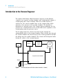
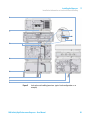
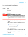
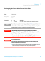
The Agilent 1260 Infinity High Performance Degasser, model G4225A,
comprises four separate vacuum chambers with semipermeable tubings, a
vacuum pump and control assembly. When the vacuum degasser is
switched on, the control assembly turns on the vacuum pump, which
generates a low pressure in the vacuum chambers. The pressure is
measured by a pressure sensor. The vacuum degasser maintains the low
pressure by a controlled leak in the air inlet filter and a regulation of the
vacuum pump using the pressure sensor.
The LC pump draws the solvents from their bottles through the
semipermeable tubes of the vacuum chambers. When solvents pass through
the vacuum chambers any dissolved gas in the solvents permeates through
the tubings into the vacuum chambers. The solvents will be degassed when
leaving the outlets of the vacuum degasser.
J=EA8
Ejbe
8dcigda
X^gXj^i
HZchdg
KVXjjb
ejbe
)hZeVgViZkVXjjbX]VbWZgh
HdakZci
KVXjjbXdciV^cZg
Figure 1
8
Overview (only one of the four solvent channels is shown)
1260 Infinity High Performance Degasser - User Manual
Introduction
System Overview
1
System Overview
Leak and Waste Handling
The 1200 Infinity Series has been designed for safe leak and waste
handling. It is important that all security concepts are understood and
instructions are carefully followed.
1260 Infinity High Performance Degasser - User Manual
9
1
Introduction
System Overview
&
6
'
7
8
(
)
*
,
+
,
Figure 2
10
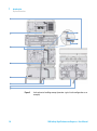
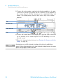
Leak and waste handling concept (overview - typical stack configuration as an
example)
1260 Infinity High Performance Degasser - User Manual
1
Introduction
System Overview
The solvent cabinet (1) is designed to store a maximum volume of 6 L
solvent. The maximum volume for an individual bottle stored in the
solvent cabinet should not exceed 2.5 L. For details, see the usage
guideline for the Agilent 1200 Infinity Series Solvent Cabinets (a printed
copy of the guideline has been shipped with the solvent cabinet, electronic
copies are available on the Internet).
The leak pan (2) (individually designed in each module) guides solvents to
the front of the module. The concept covers also leakages on internal
parts (e.g. the detector’s flow cell). The leak sensor in the leak pan stops
the running system as soon as the leak detection level is reached.
The leak pan's outlet port (3, A) guides excessive overfill from one module
to the next, as the solvent flows into the next module’s leak funnel (3, B)
and the connected corrugated waste tube (3, C). The corrugated waste
tube guides the solvent to the next lower positioned module’s leak tray
and sensor.
The waste tube of the sampler’s needle wash port (4) guides solvents to
waste.
The condense drain outlet of the autosampler cooler (5) guides condensate
to waste.
The waste tube of the purge valve (6) guides solvents to waste.
The waste tube connected to the leak pan outlet on each of the bottom
instruments (7) guides the solvent to a suitable waste container.
1260 Infinity High Performance Degasser - User Manual
11
1
12
Introduction
System Overview
1260 Infinity High Performance Degasser - User Manual
1260 Infinity High Performance Degasser - User Manual
2
Site Requirements and Specifications
Site Requirements
14
Physical Specifications
17
Performance Specifications
18
This chapter provides information on environmental requirements, physical and
performance specifications.
Agilent Technologies
13
2
Site Requirements and Specifications
Site Requirements
Site Requirements
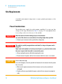
A suitable environment is important to ensure optimal performance of the
instrument.
Power Considerations
The module power supply has wide ranging capability. It accepts any line
voltage in the range described in Table 1 on page 17. Consequently there
is no voltage selector in the rear of the module.
WA R N I N G
Hazard of electrical shock or damage of your instrumentation
can result, if the devices are connected to a line voltage higher than specified.
➔ Connect your instrument to the specified line voltage only.
WA R N I N G
The module is partially energized when switched off, as long as the power cord is
plugged in.
Repair work at the module can lead to personal injuries, e.g. electrical shock, when
the cover is opened and the module is connected to power.
➔ Always unplug the power cable before opening the cover.
➔ Do not connect the power cable to the instrument while the covers are removed.
CAUTION
Inaccessible power plug.
In case of emergency it must be possible to disconnect the instrument from the power
line at any time.
➔ Make sure the power connector of the instrument can be easily reached and
unplugged.
➔ Provide sufficient space behind the power socket of the instrument to unplug the
cable.
14
1260 Infinity High Performance Degasser - User Manual
2
Site Requirements and Specifications
Site Requirements
Power Cords
Different power cords are offered as options with the module. The female
end of all power cords is identical. It plugs into the power- input socket at
the rear. The male end of each power cord is different and designed to
match the wall socket of a particular country or region.
WA R N I N G
Absence of ground connection or use of unspecified power cord
The absence of ground connection or the use of unspecified power cord can lead to
electric shock or short circuit.
➔ Never operate your instrumentation from a power outlet that has no ground
connection.
➔ Never use a power cord other than the Agilent Technologies power cord designed
for your region.
WA R N I N G
Use of unsupplied cables
Using cables not supplied by Agilent Technologies can lead to damage of the
electronic components or personal injury.
➔ Never use cables other than the ones supplied by Agilent Technologies to ensure
proper functionality and compliance with safety or EMC regulations.
WA R N I N G
Unintended use of supplied power cords
Using power cords for unintended purposes can lead to personal injury or damage of
electronic equipment.
➔ Never use the power cords that Agilent Technologies supplies with this instrument
for any other equipment.
1260 Infinity High Performance Degasser - User Manual
15
2
Site Requirements and Specifications
Site Requirements
Bench Space
The module dimensions and weight (see Table 1 on page 17) allow you to
place the module on almost any desk or laboratory bench. It needs an
additional 2.5 cm (1.0 inches) of space on either side and approximately
8 cm (3.1 inches) in the rear for air circulation and electric connections.
If the bench shall carry a complete HPLC system, make sure that the
bench is designed to bear the weight of all modules.
The module should be operated in a horizontal position.
Condensation
CAUTION
Condensation within the module
Condensation will damage the system electronics.
➔ Do not store, ship or use your module under conditions where temperature
fluctuations could cause condensation within the module.
➔ If your module was shipped in cold weather, leave it in its box and allow it to warm
slowly to room temperature to avoid condensation.
16
1260 Infinity High Performance Degasser - User Manual
2
Site Requirements and Specifications
Physical Specifications
Physical Specifications
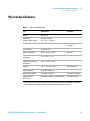
Table 1
Physical Specifications
Type
Specification
Weight
5 kg (11 lbs)
Dimensions
(height × width × depth)
80 x 345 × 435 mm
(3.1 x 13.5 × 17 inches)
Line voltage
100 – 240 V~, ± 10 %
Line frequency
50 or 60 Hz, ± 5 %
Power consumption
30 VA / 30 W / 102 BTU
Ambient operating
temperature
0 – 55 °C (32 – 131 °F) 1
Ambient non-operating
temperature
-40 – 70 °C (-40 – 158 °F)
Humidity
< 95 % r.h. at 40 °C (104 °F)
Operating altitude
Up to 2000 m (6562 ft)
Non-operating altitude
Up to 4600 m (15091 ft)
For storing the module
Safety standards:
IEC, CSA, UL
Installation category II, Pollution degree 2
For indoor use only.
1
Comments
Wide-ranging
capability
Maximum
Non-condensing
This temperature range represents the technical specifications for this instrument. The temperatures mentioned may not be suitable for all applications and all types of solvent.
1260 Infinity High Performance Degasser - User Manual
17
2
Site Requirements and Specifications
Performance Specifications
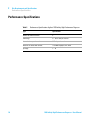
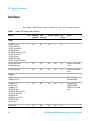
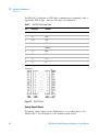
Performance Specifications
Table 2
18
Performance Specifications Agilent 1260 Infinity High Performance Degasser
Type
Specification
Number of solvent channels
4
Flow range
0 – 10 mL/min per channel
Internal volume per channel
0.45 mL per channel
Materials in contact with solvent
TFE/PDD Copolymer, FEP, PEEK
pH range
1 – 14
1260 Infinity High Performance Degasser - User Manual
1260 Infinity High Performance Degasser - User Manual
3
Installing the Degasser
Unpacking the Vacuum Degasser
20
Optimizing the Stack Configuration
One Stack Configuration 22
21
Installation Information on Leak and Waste Handling
Installing the Vacuum Degasser
24
28
Flow Connections to the Vacuum Degasser
31
Operational Hints for the Vacuum Degasser 34
General Priming Instructions 34
Priming the Degasser with the Pump 35
Priming the Degasser with a Syringe (only recommended if priming
with the pump fails) 36
Transporting the Vacuum Degasser
37
This chapter gives information about the preferred stack setup for your system
and the installation of your module.
Agilent Technologies
19
3
Installing the Degasser
Unpacking the Vacuum Degasser
Unpacking the Vacuum Degasser
Damaged Packaging
If the delivery packaging shows signs of external damage, please call your
Agilent Technologies sales and service office immediately. Inform your
service representative that the instrument may have been damaged during
shipment.
CAUTION
"Defective on arrival" problems
If there are signs of damage, please do not attempt to install the module. Inspection by
Agilent is required to evaluate if the instrument is in good condition or damaged.
➔ Notify your Agilent sales and service office about the damage.
➔ An Agilent service representative will inspect the instrument at your site and
initiate appropriate actions.
Delivery Checklist
Ensure all parts and materials have been delivered with your module. The
delivery checklist is shown below. For parts identification please check the
illustrated parts breakdown in “Parts for Maintenance” on page 65. Please
report any missing or damaged parts to your local Agilent Technologies
sales and service office.
Vacuum Degasser Delivery Checklist
p/n
Description
Vacuum Degasser
Power cord
20
G4800-64005
LC HW User Information + Utilities DVD
G1379-68705
Accessory Kit
for 1260 Infinity High Performance Degasser
1260 Infinity High Performance Degasser - User Manual
3
Installing the Degasser
Optimizing the Stack Configuration
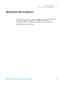
Optimizing the Stack Configuration
If your module is part of a complete Agilent Liquid Chromatograph, you
can ensure optimum performance by installing the following
configurations. These configurations optimize the system flow path,
ensuring minimum delay volume.
1260 Infinity High Performance Degasser - User Manual
21
3
Installing the Degasser
Optimizing the Stack Configuration
One Stack Configuration
Ensure optimum performance by installing the modules of the Agilent
1260 Infinity LC System in the following configuration (See Figure 3 on
page 22 and Figure 4 on page 23). This configuration optimizes the flow
path for minimum delay volume and minimizes the bench space required.
HdakZciXVW^cZi
KVXjjbYZ\VhhZg
Ejbe
>chiVciE^adi
6jidhVbeaZg
8dajbcXdbeVgibZci
9ZiZXidg
Figure 3
22
Recommended Stack Configuration for 1260 Infinity (Front View)
1260 Infinity High Performance Degasser - User Manual
3
Installing the Degasser
Optimizing the Stack Configuration
GZbdiZXVWaZ
86C7jhXVWaZid
>chiVciE^adi
68edlZg
86C7jhXVWaZ
6cVad\YZiZXidg
h^\cVa
&dg'djiejih
eZgYZiZXidg
A6CidA88]ZbHiVi^dc
adXVi^dcYZeZcYhdcYZiZXidg
Figure 4
Recommended Stack Configuration for 1260 Infinity (Rear View)
1260 Infinity High Performance Degasser - User Manual
23
3
Installing the Degasser
Installation Information on Leak and Waste Handling
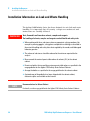
Installation Information on Leak and Waste Handling
The Agilent 1200 Infinity Series has been designed for safe leak and waste
handling. It is important that all security concepts are understood and
instructions are carefully followed.
WA R N I N G
Toxic, flammable and hazardous solvents, samples and reagents
The handling of solvents, samples and reagents can hold health and safety risks.
➔ When working with these substances observe appropriate safety procedures (for
example by wearing goggles, safety gloves and protective clothing) as described in
the material handling and safety data sheet supplied by the vendor, and follow good
laboratory practice.
➔ The volume of substances should be reduced to the minimum required for the
analysis.
➔ Never exceed the maximal permissible volume of solvents (6 L) in the solvent
cabinet.
➔ Do not use bottles that exceed the maximum permissible volume as specified in the
usage guideline for the Agilent 1200 Infinity Series Solvent Cabinets.
➔ Arrange the bottles as specified in the usage guideline for the solvent cabinet.
➔ A printed copy of the guideline has been shipped with the solvent cabinet,
electronic copies are available on the Internet.
NOTE
Recommendations for Solvent Cabinet
For details, see the usage guideline for the Agilent 1200 Infinity Series Solvent Cabinets.
24
1260 Infinity High Performance Degasser - User Manual
Installing the Degasser
Installation Information on Leak and Waste Handling
3
&
6
'
7
8
(
)
*
,
+
,
Figure 5
Leak and waste handling (overview - typical stack configuration as an
example)
1260 Infinity High Performance Degasser - User Manual
25
3
Installing the Degasser
Installation Information on Leak and Waste Handling
1
Solvent cabinet
2
Leak pan
3
Leak pan's outlet port (A), leak funnel (B) and corrugated waste tube (C)
4
Waste tube of the sampler’s needle wash
5
Condense drain outlet of the autosampler cooler
6
Waste tube of the purge valve
7
Waste tube
1 Stack the modules according to the adequate stack configuration.
The leak pan outlet of the upper module must be vertically positioned
above the leak tray of the lower module, see Figure 5 on page 25.
2 Connect data and power cables to the modules, see section Installing
the Module below.
3 Connect capillaries and tubes to the modules, see section Flow
Connections to the module below or the relevant system manual.
WA R N I N G
Toxic, flammable and hazardous solvents, samples and reagents
➔ Keep solvent path free from blockages.
➔ Keep the flow path closed (in case the pump in the system is equipped with a
passive inlet valve, solvent may leak out due to hydrostatic pressure, even if your
instrument is off).
➔ Avoid loops.
➔ Tubes must not sag.
➔ Do not bend tubes.
➔ Do not immerse tube end in waste liquid.
➔ Do not intubate tubes in other tubes.
➔ For correct tubing follow instructions on label attached to the module.
26
1260 Infinity High Performance Degasser - User Manual
Installing the Degasser
Installation Information on Leak and Waste Handling
Figure 6
3
Warning label (illustration for correct waste tubing)
1260 Infinity High Performance Degasser - User Manual
27
3
Installing the Degasser
Installing the Vacuum Degasser
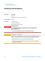
Installing the Vacuum Degasser
Parts required
Description
Power cord
Remote Cable, see “Cable Overview” on page 70
Hardware required
Degasser
Preparations
Locate bench space
Provide power connections
Unpack the vacuum degasser module
WA R N I N G
Abnormal conditions
In case of abnormal conditions during operation, the instrument must be
disconnected from line.
➔ To disconnect the instrument from line, unplug the power cord.
CAUTION
"Defective on arrival" problems
If there are signs of damage, please do not attempt to install the module. Inspection by
Agilent is required to evaluate if the instrument is in good condition or damaged.
➔ Notify your Agilent sales and service office about the damage.
➔ An Agilent service representative will inspect the instrument at your site and
initiate appropriate actions.
28
1260 Infinity High Performance Degasser - User Manual
3
Installing the Degasser
Installing the Vacuum Degasser
1 Place the vacuum degasser on the bench.
2 Ensure the power switch on the front of the vacuum degasser is OFF
(switch stands out).
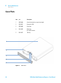
3 Connect the power cable to the power connector at the rear of the
vacuum degasser.
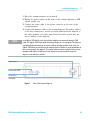
4 Connect the interface cable to the vacuum degasser. The remote cable is
a one way connection to send a not- ready signal from the degasser to
the other modules or to shut down down the whole system after an
error condition of the degasser.
NOTE
In an Agilent 1260 Infinity stack, the individual modules are connected through a CAN
cable. The Agilent 1260 Infinity High Performance Degasser is an exception. The degasser
can optionally be connected via the remote cable to the other modules of the stack. An
Agilent 1260 Infinity Instant Pilot can be connected to the CAN bus at any of the modules in
the system except for the degasser. The control software can be connected to the system
through a LAN cable (via LAN-Card) to the detector or any other module except the
degasser, if no detector is present.
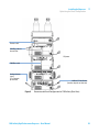
EdlZghdX`Zi
GZbdiZXVWaZhdX`Zi
GH'('hdX`Zi
;jhZ]daYZg
Figure 7
Rear of the Vacuum Degasser
1260 Infinity High Performance Degasser - User Manual
29
3
Installing the Degasser
Installing the Vacuum Degasser
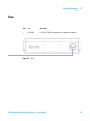
HiVijh^cY^XVidg
LVhiZdjiaZi
EdlZghl^iX]
BdYjaZineZVcY
hZg^VacjbWZg
Figure 8
Front of the Vacuum Degasser
5 Press in the power switch to turn ON the vacuum degasser.
NOTE
30
The power switch stays pressed in and a green indicator lamp in the power switch is ON
when the vacuum degasser is turned ON. When the line power switch stands out and the
green light is OFF, the vacuum degasser is turned OFF.
1260 Infinity High Performance Degasser - User Manual
Installing the Degasser
Flow Connections to the Vacuum Degasser
3
Flow Connections to the Vacuum Degasser
Parts required
Description
Solvent cabinet including solvent bottles (filled with solvent) and bottle head assemblies
Solvent outlet tubes
Syringe with adapter
Hardware required
Degasser
Preparations
Install the degasser
WA R N I N G
When opening capillary or tube fittings, solvents may leak out.
The handling of toxic and hazardous solvents and reagents can carry health risks.
➔ Observe appropriate safety procedures (for example, wear goggles, safety gloves
and protective clothing) as described in the material handling and safety data sheet
supplied by the solvent vendor, especially when toxic or hazardous solvents are
used.
1 Put the solvent cabinet with the bottle(s) on top of the vacuum
degasser.
2 Remove the front cover by pressing the snap fasteners on both sides.
Figure 9
Removing the Front Cover
3 If the vacuum degasser is not used with an Agilent 1260 Infinity pump,
connect the waste tube from the accessory kit to the waste outlet and
place into your waste system.
4 Put the bottle head assemblies into solvent bottles containing your
mobile phase.
1260 Infinity High Performance Degasser - User Manual
31
3
Installing the Degasser
Flow Connections to the Vacuum Degasser
5 Connect the solvent tubes from the bottle head assemblies to the inlet
connectors A through D (typically the left connection of the channel) of
the vacuum degasser. Use the mounting tool for simplified holding and
fixing of the tubing fitting. Fix the tubes in the clips of the vacuum
degasser.
8a^eh
>caZiXdccZXidgh
DjiaZiXdccZXidgh
8a^eh
6 Connect the outlet tubes to the output ports (typically right connection
of the channel) of the vacuum degasser. Use the mounting tool to fix
the tube screw.
7 Prime the degasser before first use (see “Priming the Degasser with the
Pump” on page 35).
NOTE
32
Atmospheric gases can diffuse through the tubing and dissolve in the mobile phase
solvents. For best chromatographic results, keep the length of tubing between the vacuum
degasser and your pump as short as possible.
1260 Infinity High Performance Degasser - User Manual
Installing the Degasser
Flow Connections to the Vacuum Degasser
3
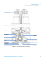
7diiaZ"]ZVYVhhZbWan
HdakZciXVW^cZi
IjWZXa^e
EgZhhjgZhZchdg
HiVi^Xb^mZg
Ejg\ZkVakZ
Ejbe]ZVYX]VccZa6
Ejbe]ZVYX]VccZa7
6YVeiZg
6Xi^kZ^caZikVakZ7
6Xi^kZ^caZikVakZ
LVhiZijW^c\
DjiaZiXVe^aaVgnidVjidhVbeaZg
Figure 10
LVhiZdjiaZi
Flow Connection to the Vacuum Degasser
1260 Infinity High Performance Degasser - User Manual
33
3
Installing the Degasser
Operational Hints for the Vacuum Degasser
Operational Hints for the Vacuum Degasser
General Priming Instructions
WA R N I N G
When opening capillary or tube fittings, solvents may leak out.
The handling of toxic and hazardous solvents and reagents can carry health risks.
➔ Observe appropriate safety procedures (for example, wear goggles, safety gloves
and protective clothing) as described in the material handling and safety data sheet
supplied by the solvent vendor, especially when toxic or hazardous solvents are
used.
Before using a new degasser or new tubings for the first time:
1 Prime all tubings with at least 5 ml of iso- propanol no matter whether
the channels will be used with organic mobile phase or with water.
If you are changing to a solvent that is immiscible with the solvent
currently in the tubing continue as follows:
2 Replace the current solvent with iso- propanol, if current solvent is
organic or with water, if current solvent is an inorganic buffer or
contains salt.
34
1260 Infinity High Performance Degasser - User Manual
Installing the Degasser
Operational Hints for the Vacuum Degasser
3
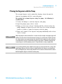
Priming the Degasser with the Pump
The vacuum degasser can be primed by drawing solvent through the
degasser by pumping with the connected pump.
For priming the vacuum degasser using the pump the following is
recommended:
1 Connect all tubings to and from degasser and pump.
2 Open the pump’s purge valve to waste.
3 Pump at a flow rate of about 5 ml/min until the solvent reaches the
pump. Pumping at higher flow rates will stress the system and might
result in a failure to prime the degasser with the pump.
4 Prime each channel of the degasser and pump individually with at least
5 mL of solvent.
NOTE
When the pump has been turned off for a certain time (for example, overnight) oxygen will
rediffuse into the solvent channels between the degasser and the pump. Volatile fractions
of a solvent mixture can evaporate from the solvent if left in the degasser with no flow for
an extended time causing a composition change of the mixture. Therefore priming of the
vacuum degasser and the pumping system is required before starting an application.
NOTE
In case priming with the pump should fail, the degasser can be primed with a syringe. This
might happen because the used solvent is highly volatile or the degasser and pump inlet
lines are completely dry and the pump therefore fails to draw the solvent from the solvent
bottle through the degasser channels into the pump.
1260 Infinity High Performance Degasser - User Manual
35
3
Installing the Degasser
Operational Hints for the Vacuum Degasser
Priming the Degasser with a Syringe (only recommended if priming
with the pump fails)
CAUTION
Damage to degasser
Drawing the solvent through the degasser very quickly might destroy the chambers.
➔ Draw the solvent through the degasser channels with moderate speed in order to
avoid damage to the chambers!
1 Disconnect solvent outlet tube of the channel that is supposed to be
primed from your pump.
2 Connect syringe adapter to solvent outlet tube.
3 Push syringe adapter onto syringe.
4 Pull syringe plunger to draw at least 5 mL of solvent through degasser
and tubing.
5 Replace the priming solvent with the new solvent of your choice.
6 Pull syringe plunger to draw at least 5 mL of solvent through degasser
and tubing.
7 Disconnect syringe adapter from solvent tube.
8 Connect solvent tube to your pump.
9 Repeat step 1 on page 36 to step 8 on page 36 for the other solvent
channels.
36
NOTE
When priming the vacuum degasser with a syringe the solvent is drawn through the
degasser tubes faster compared to priming with a pump. The solvent at the degasser outlet
will therefore not be fully degassed. Pump for approximately 5 minutes with your selected
flow rate before starting any application. This will allow the vacuum degasser to properly
degas the solvent in the degasser tubes.
NOTE
Priming the degasser with a syringe is only recommended if priming with a pump (see
“Priming the Degasser with the Pump” on page 35) fails.
1260 Infinity High Performance Degasser - User Manual
Installing the Degasser
Transporting the Vacuum Degasser
3
Transporting the Vacuum Degasser
WA R N I N G
Solvents leaking out
Solvents remaining in the solvent channels may leak out during transport. This can
possibly cause personal damage.
➔ Drain any remaining solvents from the degassing channels before transporting the
degasser.
1 Pull the solvent inlet tubing out of the solvent bottle of channel A.
2 Let the pump draw solvent and air through channel A of the degasser,
until the chamber of channel A is completely dry.
3 Repeat these steps for the remaining solvent channels.
1260 Infinity High Performance Degasser - User Manual
37
3
38
Installing the Degasser
Transporting the Vacuum Degasser
1260 Infinity High Performance Degasser - User Manual
1260 Infinity High Performance Degasser - User Manual
4
Using the Degasser
Leak and Waste Handling
40
When to Use a Vacuum Degasser
Prevent Blocking of Solvent Filters
41
42
Solvent Information 43
Material Information 43
This chapter explains how to use the module.
Agilent Technologies
39
4
Using the Degasser
Leak and Waste Handling
Leak and Waste Handling
WA R N I N G
Toxic, flammable and hazardous solvents, samples and reagents
The handling of solvents, samples and reagents can hold health and safety risks.
➔ When working with these substances observe appropriate safety procedures (for
example by wearing goggles, safety gloves and protective clothing) as described in
the material handling and safety data sheet supplied by the vendor, and follow good
laboratory practice.
➔ The volume of substances should be reduced to the minimum required for the
analysis.
➔ Do not operate the instrument in an explosive atmosphere.
➔ Never exceed the maximal permissible volume of solvents (6 L) in the solvent
cabinet.
➔ Do not use bottles that exceed the maximum permissible volume as specified in the
usage guideline for the Agilent 1200 Infinity Series Solvent Cabinets.
➔ Arrange the bottles as specified in the usage guideline for the solvent cabinet.
➔ A printed copy of the guideline has been shipped with the solvent cabinet,
electronic copies are available on the Internet.
➔ The residual free volume in the appropriate waste container must be large enough
to collect the waste liquid.
➔ Check the filling level of the waste container regularly.
➔ To achieve maximal safety, check the correct installation regularly.
NOTE
Recommendations for Solvent Cabinet
For details, see the usage guideline for the Agilent 1200 Infinity Series Solvent Cabinets.
For details on correct installation, see “Installation Information on Leak
and Waste Handling” on page 24.
40
1260 Infinity High Performance Degasser - User Manual
4
Using the Degasser
When to Use a Vacuum Degasser
When to Use a Vacuum Degasser
WA R N I N G
Unspecified Conditions
Operating the instrumentation under conditions other than its intended use might
result in a potential safety hazard or might damage the instrumentation.
➔ Never operate your instrumentation under conditions other than those specified by
the vendor.
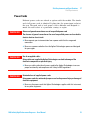
For flow rates less than 10 mL/min:
• if your detector is used with maximum sensitivity in the low UV
wavelength range,
• if your application requires optimum injection precision,
• if your application requires highest retention time reproducibility
(mandatory at flow rates below 0.5 mL/min,
• if your sample or detection is sensitive to dissolved oxygen in the
mobile phase (degradation),
• with a fluorescence detector,
• with an LC- MS- detector.
For capillary LC application with our Agilent 1260 Infinity Capillary and
Nano LC System.
Generally a degasser should be used when negative effects due to
dissolved gas in the mobile phase exceed the limits that are acceptable for
the user. Negative effects that can be caused by dissolved gas are:
• Unstable flow due to unstable pumping conditions. This may result in
an increased pressure ripple or increased standard deviations of peak
retention times and peak areas especially at low flow rates.
• Baseline noise on detectors that are sensitive to changes in the
refractive index,
• sample degradation,
• fluorescence quenching due to dissolved oxygen,
• baseline drift in electrochemical detectors due to dissolved oxygen
especially in reduction mode.
1260 Infinity High Performance Degasser - User Manual
41
4
Using the Degasser
Prevent Blocking of Solvent Filters
Prevent Blocking of Solvent Filters
Contaminated solvents or algae growth in the solvent bottle will reduce
the lifetime of the solvent filter and will influence the performance of the
pump. This is especially true for aqueous solvents or phosphate buffers
(4 – 7 pH). The following suggestions will prolong lifetime of the solvent
filter and will maintain the performance of the pump.
• Use sterile, if possible amber solvent bottles to slow down algae growth.
• Filter solvents through filters or membranes that remove algae.
• Exchange solvents every two days or refilter.
• If the application permits add 0.0001 – 0.001 M sodium azide to the
solvent.
• Place a layer of argon on top of your solvent.
• Avoid exposure of the solvent bottles to direct sunlight.
Checking the Solvent Filters
The solvent filters are on the low- pressure side of the pumping system. A
blocked filter therefore does not affect the pressure readings of the pump.
The pressure readings cannot be used to identify blocked filters. If the
solvent cabinet is placed on top of the vacuum degasser the filter
condition can be checked in the following way:
Remove the tubing at the inlet port of the vacuum degasser. If the filter is
in good condition the solvent will freely drip out of the solvent tube (due
to hydrostatic pressure). If the solvent filter is partly blocked no solvent
or only very little solvent will drip out of the solvent tube.
Cleaning the Solvent Filters
• Remove the blocked solvent filter from the bottle- head assembly and
place it in a beaker with concentrated nitric acid (35%) for one hour.
• Thoroughly flush the filter with bidistilled water (remove all nitric acid).
• Replace the filter.
NOTE
42
Never use the system without solvent filter installed.
1260 Infinity High Performance Degasser - User Manual
4
Using the Degasser
Solvent Information
Solvent Information
Observe the following recommendations on the use of solvents.
• Follow recommendations for avoiding the growth of algae, see pump
manuals.
• Small particles can permanently block capillaries and valves. Therefore,
always filter solvents through 0.4 µm filters.
• Avoid or minimize the use of solvents that may corrode parts in the
flow path. Consider specifications for the pH range given for different
materials like flow cells, valve materials etc. and recommendations in
subsequent sections.
Material Information
Materials in Flow Path
Following materials are used in the flow path of this module:
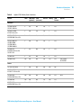
Table 3
Materials in flow path
Part
Materials
Internal tubings
TFE/PDD copolymer, PFA
Inlets
PEEK
Tubings
FEP
Fittings
ETFE
1260 Infinity High Performance Degasser - User Manual
43
4
Using the Degasser
Solvent Information
Material Information
Materials in the flow path are carefully selected based on Agilent’s
experiences in developing highest quality instruments for HPLC analysis
over several decades. These materials exhibit excellent robustness under
typical HPLC conditions. For any special conditions, please consult the
material information section or contact Agilent.
Disclaimer
Subsequent data were collected from external resources and are meant as
a reference. Agilent cannot guarantee the correctness and completeness of
such information. Data is based on compatibility libraries, which are not
specific for estimating the long- term life time under specific but highly
variable conditions of UHPLC systems, solvents, solvent mixtures and
samples. Information can also not be generalized due to catalytic effects of
impurities like metal ions, complexing agents, oxygen etc. Apart from pure
chemical corrosion, other effects like electro corrosion, electrostatic
charging (especially for non- conductive organic solvents), swelling of
polymer parts etc. need to be considered. Most data available refers to
room temperature (typically 20 – 25 °C, 68 – 77 °F). If corrosion is
possible, it usually accelerates at higher temperatures. If in doubt, please
consult technical literature on chemical compatibility of materials.
PEEK
PEEK (Polyether- Ether Ketones) combines excellent properties regarding
biocompatibility, chemical resistance, mechanical and thermal stability.
PEEK is therefore the material of choice for UHPLC and biochemical
instrumentation.
It is stable in a wide pH range, and inert to many common solvents.
There is still a number of known incompatibilities with chemicals such as
chloroform, methylene chloride, THF, DMSO, strong acids (nitric acid >
10 %, sulphuric acid > 10 %, sulfonic acids, trichloroacetic acid), halogenes
or aequous halogene solutions, phenol and derivatives (cresols, salicylic
acid etc.).
44
1260 Infinity High Performance Degasser - User Manual
4
Using the Degasser
Solvent Information
Polyimide
Agilent uses semi- crystalline polyimide for rotor seals in valves and needle
seats in autosamplers. One supplier of polyimide is DuPont, which brands
polyimide as Vespel, which is also used by Agilent.
Polyimide is stable in a pH range between 1 and 10 and in most organic
solvents. It is incompatible with concentrated mineral acids (e.g. sulphuric
acid), glacial acetic acid, DMSO and THF. It is also degraded by
nucleophilic substances like ammonia (e.g. ammonium salts in basic
conditions) or acetates.
Polyethylene (PE)
Agilent uses UHMW (ultra- high molecular weight)- PE/PTFE blends for
yellow piston and wash seals, which are used in 1290 Infinity pumps and
for normal phase applications in 1260 Infinity pumps.
Polyethylene has a good stability for most common inorganic solvents
including acids and bases in a pH range of 1 to 12.5. It is compatible to
many organic solvents used in chromatographic systems like methanol,
acetonitrile and isopropanol. It has limited stability with aliphatic,
aromatic and halogenated hydrocarbons, THF, phenol and derivatives,
concentrated acids and bases. For normal phase applications, the
maximum pressure should be limited to 200 bar.
Tantalum (Ta)
Tantalum is inert to most common HPLC solvents and almost all acids
except fluoric acid and acids with free sulfur trioxide. It can be corroded
by strong bases (e.g. hydroxide solutions > 10 %, diethylamine). It is not
recommended for the use with fluoric acid and fluorides.
1260 Infinity High Performance Degasser - User Manual
45
4
Using the Degasser
Solvent Information
Stainless Steel (ST)
Stainless steel is inert against many common solvents. It is stable in the
presence of acids and bases in a pH range of 1 to 12.5. It can be corroded
by acids below pH 2.3. It can also corrode in following solvents:
• Solutions of alkali halides, their respective acids (for example, lithium
iodide, potassium chloride, and so on) and aqueous solutions of halogens.
• High concentrations of inorganic acids like nitric acid, sulfuric acid and
organic solvents especially at higher temperatures (replace, if your
chromatography method allows, by phosphoric acid or phosphate buffer
which are less corrosive against stainless steel).
• Halogenated solvents or mixtures which form radicals and/or acids, for
example:
2 CHCl3 + O2→ 2 COCl2 + 2 HCl
This reaction, in which stainless steel probably acts as a catalyst,
occurs quickly with dried chloroform if the drying process removes the
stabilizing alcohol.
• Chromatographic grade ethers, which can contain peroxides (for
example, THF, dioxane, di- isopropylether). Such ethers should be
filtered through dry aluminium oxide which adsorbs the peroxides.
• Solutions of organic acids (acetic acid, formic acid, and so on) in
organic solvents. For example, a 1 % solution of acetic acid in methanol
will attack steel.
• Solutions containing strong complexing agents (for example, EDTA,
ethylene diamine tetra- acetic acid).
• Mixtures of carbon tetrachloride with 2- propanol or THF.
Diamond-Like Carbon (DLC)
Diamond- Like Carbon is inert to almost all common acids, bases and
solvents. There are no documented incompatibilities for HPLC applications.
Fused silica and Quartz (SiO2)
Fused silica is used in 1290 Infinity Flow Cells and capillaries. Quartz is
used for classical flow cell windows. It is inert against all common
solvents and acids except hydrofluoric acid and acidic solvents containing
fluorides. It is corroded by strong bases and should not be used above pH
12 at room temperature. The corrosion of flow cell windows can negatively
affect measurement results. For a pH greater than 12, the use of flow cells
with sapphire windows is recommended.
46
1260 Infinity High Performance Degasser - User Manual
Using the Degasser
Solvent Information
4
Gold
Gold is inert to all common HPLC solvents, acids and bases within the
specified pH range. It can be corroded by complexing cyanides and
concentrated acids like aqua regia.
Zirconium Oxide (ZrO2)
Zirconium Oxide is inert to almost all common acids, bases and solvents.
There are no documented incompatibilities for HPLC applications.
Platinum/Iridium
Platinum/Iridium is inert to almost all common acids, bases and solvents.
There are no documented incompatibilities for HPLC applications.
Fluorinated polymers (PTFE, PFA, FEP, FFKM)
Fluorinated polymers like PTFE (polytetrafluorethylene), PFA
(perfluoroalkoxy) and FEP (fluorinated ethylene propylene) are inert to
almost all common acids, bases, and solvents. FFKM is perfluorinated
rubber, which is also resistant to most chemicals. As an elastomer, it may
swell in some organic solvents like halogenated hydrocarbons.
TFE/PDD copolymer tubings, which are used in all Agilent degassers
except G1322A, are not compatible with fluorinated solvents like Freon,
Fluorinert, or Vertrel. They have limited life time in the presence of
Hexafluoroisopropanol (HFIP). To ensure the longest possible life with
HFIP, it is best to dedicate a particular chamber to this solvent, not to
switch solvents, and not to let dry out the chamber. For optimizing the life
of the pressure sensor, do not leave HFIP in the chamber when the unit is
off.
Sapphire, Ruby and Al2O3-based ceramics
Sapphire, ruby and ceramics based on aluminum oxide Al2O3 are inert to
almost all common acids, bases and solvents. There are no documented
incompatibilities for HPLC applications.
1260 Infinity High Performance Degasser - User Manual
47
4
48
Using the Degasser
Solvent Information
1260 Infinity High Performance Degasser - User Manual
1260 Infinity High Performance Degasser - User Manual
5
Optimizing Performance
Increasing the Degasser Performance and Degassing Level
50
This chapter gives hints on how to optimize the performance or use additional
devices.
Agilent Technologies
49
5
Optimizing Performance
Increasing the Degasser Performance and Degassing Level
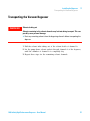
Increasing the Degasser Performance and Degassing Level
For some critical applications it might be useful to increase the
degasser’s performance and degassing level by using two channels of
the degasser in series with only one solvent channel of the pump. For
doing so:
1 Connect the solvent inlet tubing (bottle head assembly, Bottle- head
assembly (G1311- 60003)) coming from the solvent bottle to the inlet
line of the first channel, you want to use.
2 Connect the outlet of the first channel to the inlet if the 2nd solvent
channel of the degasser with the help of the short connecting tubing
(p/n G1379- 68706), delivered with the accessory kit of the degasser.
3 Connect to the outlet of the 2nd channel of the degasser and into the
pump.
[gdbWdiiaZ
idejbe
Figure 11
50
Connecting two degasser channels in series
1260 Infinity High Performance Degasser - User Manual
1260 Infinity High Performance Degasser - User Manual
6
Troubleshooting and Diagnostics
Overview of the Degasser's Indicators
Status Indicators
52
53
Module Status Indicator
54
Hardware Symptoms 55
All Lamps are Off 55
If the Status Indicator is Red 56
If the Status Indicator is Yellow and the Vacuum Pump is not
Running 56
Status Indicator becomes Red and Vacuum Pump was Running
56
This chapter gives an overview about the troubleshooting and diagnostic
features and the different user interfaces.
Agilent Technologies
51
6
Troubleshooting and Diagnostics
Overview of the Degasser's Indicators
Overview of the Degasser's Indicators
Status Indicators
The vacuum degasser is provided with two status indicators which
indicate the operational state (ready, busy, and error states) of the
vacuum degasser. The status indicators provide a quick visual check of the
operation of the vacuum degasser (see Figure 12 on page 53).
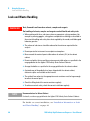
Hardware Symptoms
A red status lamp at the vacuum degasser indicates a problem with the
vacuum system or with the electronic control. The vacuum degasser
generates an error output on the remote lines. The following pages
describe hardware symptoms which help you to isolate the cause of a
hardware failure (see “Hardware Symptoms” on page 55).
52
1260 Infinity High Performance Degasser - User Manual
Troubleshooting and Diagnostics
Status Indicators
6
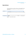
Status Indicators
Two status indicators are located on the front of the module. The lower
left indicates the power supply status, the upper right indicates the
module status.
HiVijh^cY^XVidg
EdlZghjeean^cY^XVidg
Figure 12
Location of Status Indicators
1260 Infinity High Performance Degasser - User Manual
53
6
Troubleshooting and Diagnostics
Module Status Indicator
Module Status Indicator
The module status indicator indicates one of six possible module conditions:
• When the status indicator is OFF (and power switch light is on), the
module is in a prerun condition, and is ready to begin an analysis.
• A green status indicator, indicates the module is performing an analysis
(run mode).
• A yellow indicator indicates a not- ready condition. The module is in a
not- ready state when it is waiting for a specific condition to be reached
or completed (for example, immediately after changing a set point), or
while a self- test procedure is running.
• An error condition is indicated when the status indicator is red. An
error condition indicates the module has detected an internal problem
which affects correct operation of the module. Usually, an error
condition requires attention (e.g. leak, defective internal components).
An error condition always interrupts the analysis.
If the error occurs during analysis, it is propagated within the LC
system, i.e. a red LED may indicate a problem of a different module.
Use the status display of your user interface for finding the root
cause/module of the error.
• A blinking indicator indicates that the module is in resident mode (e.g.
during update of main firmware).
• A fast blinking indicator indicates that the module is in boot loader
mode (e.g. during update of main firmware). In such a case try to
re- boot the module or try a cold- start.
CAUTION
Red status LED indicates error
This indicates either an internal leak in the vacuum system or an electronic failure.
➔ To prevent any damage, switch off the vacuum degasser and remove the solvent
bottles from the solvent cabinet to stop any gravity-caused flow of solvent into the
vacuum chamber.
➔ In case of an internal leak it is possible that solvent may enter the vacuum chamber
and solvent may leak into the waste drain.
➔ Apply troubleshhoting information in “If the Status Indicator is Red” on page 56.
54
1260 Infinity High Performance Degasser - User Manual
Troubleshooting and Diagnostics
Hardware Symptoms
6
Hardware Symptoms
In case of a problem with the vacuum system or the electronic control the
vacuum degasser status lamp will be red. The vacuum degasser will
generate an error output on the remote lines. This will shut down other
system modules when connected via remote cable, see “Installing the
Vacuum Degasser” on page 28. The vacuum degasser itself is not able to
generate any error messages in the Agilent 1260 Infinity system logbook.
The following pages describe hardware symptoms which help you to
isolate the cause of a hardware failure.
All Lamps are Off
If all other modules in the system are on (power switch lamp is green)
and are recognized by the connected user interface (module parameters
can be set, module- specific screens appear, and so on), then do the
following to determine the problem with the vacuum degasser:
✔ Ensure the power cable is connected to the degasser, and the power
cable is connected to line power.
✔ Ensure the power switch on the front of the module is ON.
✔ Ensure the power fuses are OK.
The fuse holders are located on the rear panel of the vacuum degasser
and are part of the power socket. Check the fuses (see “Exchanging the
Fuses of the Power Inline Filter” on page 63), and change if necessary:
✔ If the previous steps did not solve the problem, contact your Agilent
service representative.
1260 Infinity High Performance Degasser - User Manual
55
6
Troubleshooting and Diagnostics
Hardware Symptoms
If the Status Indicator is Red
Sufficient vacuum is normally built up after the initial start- up and
controlled by the pressure sensor.
If the vacuum cannot be reached, the vacuum degasser will switch to the
error state. The error condition can be reset by turning the vacuum
degasser off and on again.
If the Status Indicator is Yellow and the Vacuum Pump is not
Running
NOTE
The status indicator is yellow during the startup phase of the degasser until the operating
pressure is reached. This may take several minutes.
Please contact your Agilent service representative.
Status Indicator becomes Red and Vacuum Pump was Running
Sufficient vacuum is normally built up after the initial start- up and
controlled by the pressure sensor.
If the vacuum cannot be reached, the vacuum degasser will switch to the
error state. The error condition can be reset by turning the vacuum
degasser off and on again.
The following parts can be responsible for an insufficient vacuum:
1 Leaky tubing,
2 leaky or defective internal parts.
Contact your Agilent service representative.
56
1260 Infinity High Performance Degasser - User Manual
1260 Infinity High Performance Degasser - User Manual
7
Maintenance
Warnings and Cautions
58
Introduction to Maintenance
Cleaning the Module
60
61
Assembling the Main Cover
62
Exchanging the Fuses of the Power Inline Filter
63
This chapter describes the maintenance of the module.
Agilent Technologies
57
7
Maintenance
Warnings and Cautions
Warnings and Cautions
WA R N I N G
Toxic, flammable and hazardous solvents, samples and reagents
The handling of solvents, samples and reagents can hold health and safety risks.
➔ When working with these substances observe appropriate safety procedures (for
example by wearing goggles, safety gloves and protective clothing) as described in
the material handling and safety data sheet supplied by the vendor, and follow good
laboratory practice.
➔ The volume of substances should be reduced to the minimum required for the
analysis.
➔ Do not operate the instrument in an explosive atmosphere.
WA R N I N G
Electrical shock
Repair work at the module can lead to personal injuries, e.g. shock hazard, when the
cover is opened.
➔ Do not remove the cover of the module.
➔ Only certified persons are authorized to carry out repairs inside the module.
WA R N I N G
Personal injury or damage to the product
Agilent is not responsible for any damages caused, in whole or in part, by improper
use of the products, unauthorized alterations, adjustments or modifications to the
products, failure to comply with procedures in Agilent product user guides, or use of
the products in violation of applicable laws, rules or regulations.
➔ Use your Agilent products only in the manner described in the Agilent product user
guides.
58
1260 Infinity High Performance Degasser - User Manual
7
Maintenance
Warnings and Cautions
WA R N I N G
Sharp metal edges
Sharp-edged parts of the equipment may cause injuries.
➔ To prevent personal injury, be careful when getting in contact with sharp metal
areas.
CAUTION
Safety standards for external equipment
➔ If you connect external equipment to the instrument, make sure that you only use
accessory units tested and approved according to the safety standards appropriate
for the type of external equipment.
1260 Infinity High Performance Degasser - User Manual
59
7
Maintenance
Introduction to Maintenance
Introduction to Maintenance
The vacuum degasser is designed for easy repair. The most frequent
repairs such as exchanging power fuses and assembling the main cover
can be performed by the user.
60
1260 Infinity High Performance Degasser - User Manual
Maintenance
Cleaning the Module
7
Cleaning the Module
To keep the module case clean, use a soft cloth slightly dampened with
water, or a solution of water and mild detergent.
WA R N I N G
Liquid dripping into the electronic compartment of your module can cause shock
hazard and damage the module
➔ Do not use an excessively damp cloth during cleaning.
➔ Drain all solvent lines before opening any connections in the flow path.
1260 Infinity High Performance Degasser - User Manual
61
7
Maintenance
Assembling the Main Cover
Assembling the Main Cover
When
If cover is broken
Tools required
Description
None
Parts required
CAUTION
#
p/n
Description
1
5065-9989
Cover kit (includes base, top, left and right)
Wrong assembly
Once installed wrongly, you may not be able to remove the side from the top part.
➔ Make sure to install the side parts in the correct orientation.
1 Place the top part on the bench and insert the left and
2 Replace the cover.
right side into the top part.
;gdci
Next Steps:
3 Replace the vacuum degasser in the stack and reconnect the cables and capillaries.
4 Turn on the vacuum degasser.
62
1260 Infinity High Performance Degasser - User Manual
7
Maintenance
Exchanging the Fuses of the Power Inline Filter
Exchanging the Fuses of the Power Inline Filter
When
When defective
Tools required
Description
None
Parts required
NOTE
WA R N I N G
#
p/n
Description
2
2110-0458
Fuse: 250V, T 500 mA, compatible to all supported line voltages
The module power supply has wide-ranging capability (see Table 1 on page 17). It accepts
any line voltage in the range mentioned in the table. Consequently there is no voltage
selector in the rear of the module. There are two externally accessible fuses, that protect
the power supply. These fuses are identical for all accepted line voltages.
Potential hazard of physical injury or death or damage to the instrument.
Using fuses other than the one specified for this module and purpose can lead to
personal injury or damage of the electronic components.
➔ Never use fuses other than the ones supplied by Agilent Technologies to ensure
proper functionality and compliance with safety or EMC regulations.
WA R N I N G
Use of unsupplied cables
Using cables not supplied by Agilent Technologies can lead to damage of the
electronic components or personal injury.
➔ Never use cables other than the ones supplied by Agilent Technologies to ensure
proper functionality and compliance with safety or EMC regulations.
1260 Infinity High Performance Degasser - User Manual
63
7
Maintenance
Exchanging the Fuses of the Power Inline Filter
1 Switch off the power switch at the front of the instrument.
2 Remove the power cable from the power connector at the rear of the
instrument.
3 Press down the clip of the fuse holder and pull out of the power socket.
8a^e
;jhZ]daYZg
4 Remove the fuses from the fuse holder.
5 Ensure the fuse wires inside the fuses are not broken. If a test meter is
available, check the resistance of each fuse. A good fuse shows a low
resistance (typically less than 1 Ohm).
6 If a fuse is defective (wire broken or high resistance), insert a new fuse.
7 Reinsert the fuse holder and the power cable.
8 Switch on the power switch.
64
1260 Infinity High Performance Degasser - User Manual
1260 Infinity High Performance Degasser - User Manual
8
Parts for Maintenance
Cover Parts
Fuse
66
67
Accessory Kit
68
This chapter provides information on parts for maintenance.
Agilent Technologies
65
8
Parts for Maintenance
Cover Parts
Cover Parts
Item
p/n
Description
1
5065-9989
Cover kit (includes base, top, left and right)
2
5043-0207
Name plate 1260
3
5065-9990
Front cover
4
5041-8365
Blank plug
for unused channels
5
5041-8387
Tube clip
&
'
(
)
*
Figure 13
66
Cover Parts
1260 Infinity High Performance Degasser - User Manual
Parts for Maintenance
Fuse
8
Fuse
Item
p/n
Description
1
2110-0458
Fuse: 250V, T 500 mA, compatible to all supported line voltages
&
Figure 14
Fuse
1260 Infinity High Performance Degasser - User Manual
67
8
Parts for Maintenance
Accessory Kit
Accessory Kit
68
Item
p/n
Description
1
G1379-68705
Accessory Kit
for 1260 Infinity High Performance Degasser
2
G1379-68706
Connecting tubing (to connect to channels in series for increased
performance) 2x
3
G1322-67300
Kit of 4 solvent tubes including labels
for connection degasser to MCGV (Quaternary Pump)
4
5062-2461
Waste tube, 5 m (reorder pack)
5
0100-1710
Mounting Tool for Tubing Connections
6
5061-3378
Remote Cable
1260 Infinity High Performance Degasser - User Manual
1260 Infinity High Performance Degasser - User Manual
9
Identifying Cables
Cable Overview
70
Analog Cables
72
Remote Cables
74
BCD Cables
CAN Cable
77
79
External Contact Cable
Agilent Module to PC
80
81
Agilent 1200 Module to Printer
82
This chapter provides information on cables used with the Agilent 1200 Infinity
Series modules.
Agilent Technologies
69
9
Identifying Cables
Cable Overview
Cable Overview
NOTE
Never use cables other than the ones supplied by Agilent Technologies to ensure proper
functionality and compliance with safety or EMC regulations.
Analog cables
p/n
Description
35900-60750
Agilent module to 3394/6 integrators
35900-60750
Agilent 35900A A/D converter
01046-60105
Analog cable (BNC to general purpose, spade lugs)
Remote cables
p/n
Description
03394-60600
Agilent module to 3396A Series I integrators
3396 Series II / 3395A integrator, see details in section “Remote
Cables” on page 74
03396-61010
Agilent module to 3396 Series III / 3395B integrators
5061-3378
Remote Cable
01046-60201
Agilent module to general purpose
BCD cables
70
p/n
Description
03396-60560
Agilent module to 3396 integrators
G1351-81600
Agilent module to general purpose
1260 Infinity High Performance Degasser - User Manual
Identifying Cables
Cable Overview
9
CAN cables
p/n
Description
5181-1516
CAN cable, Agilent module to module, 0.5 m
5181-1519
CAN cable, Agilent module to module, 1 m
LAN cables
p/n
Description
5023-0203
Cross-over network cable, shielded, 3 m (for point to point connection)
5023-0202
Twisted pair network cable, shielded, 7 m (for point to point
connection)
External Contact Cable
p/n
Description
G1103-61611
General Purpose Cable
RS-232 cables
p/n
Description
G1530-60600
RS-232 cable, 2 m
RS232-61601
RS-232 cable, 2.5 m
Instrument to PC, 9-to-9 pin (female). This cable has special pin-out,
and is not compatible with connecting printers and plotters. It's also
called "Null Modem Cable" with full handshaking where the wiring is
made between pins 1-1, 2-3, 3-2, 4-6, 5-5, 6-4, 7-8, 8-7, 9-9.
5181-1561
RS-232 cable, 8 m
1260 Infinity High Performance Degasser - User Manual
71
9
Identifying Cables
Analog Cables
Analog Cables
One end of these cables provides a BNC connector to be connected to
Agilent modules. The other end depends on the instrument to which
connection is being made.
Agilent Module to 3394/6 Integrators
p/n 35900-60750
Pin 3394/6
Pin Agilent
module
1
Signal Name
Not connected
2
Shield
Analog -
3
Center
Analog +
Pin BNC
Pin Agilent
module
Signal Name
Shield
Shield
Analog -
Center
Center
Analog +
Agilent Module to BNC Connector
p/n 8120-1840
72
1260 Infinity High Performance Degasser - User Manual
Identifying Cables
Analog Cables
9
Agilent Module to General Purpose
p/n 01046-60105
Pin
Pin Agilent
module
1
Signal Name
Not connected
2
Black
Analog -
3
Red
Analog +
1260 Infinity High Performance Degasser - User Manual
73
9
Identifying Cables
Remote Cables
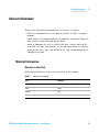
Remote Cables
One end of these cables provides a Agilent Technologies APG (Analytical
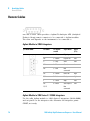
Products Group) remote connector to be connected to Agilent modules.
The other end depends on the instrument to be connected to.
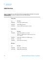
Agilent Module to 3396A Integrators
p/n 03394-60600
Pin 3396A
Pin Agilent
module
Signal Name
9
1 - White
Digital ground
NC
2 - Brown
Prepare run
Low
3
3 - Gray
Start
Low
NC
4 - Blue
Shut down
Low
NC
5 - Pink
Not
connected
NC
6 - Yellow
Power on
High
5,14
7 - Red
Ready
High
1
8 - Green
Stop
Low
NC
9 - Black
Start request
Low
13, 15
Active
(TTL)
Not
connected
Agilent Module to 3396 Series II / 3395A Integrators
Use the cable Agilent module to 3396A Series I integrators (03394- 60600)
and cut pin #5 on the integrator side. Otherwise the integrator prints
START; not ready.
74
1260 Infinity High Performance Degasser - User Manual
Identifying Cables
Remote Cables
9
Agilent Module to 3396 Series III / 3395B Integrators
p/n 03396-61010
Pin 33XX
Pin Agilent
module
Signal Name
9
1 - White
Digital ground
NC
2 - Brown
Prepare run
Low
3
3 - Gray
Start
Low
NC
4 - Blue
Shut down
Low
NC
5 - Pink
Not
connected
NC
6 - Yellow
Power on
High
14
7 - Red
Ready
High
4
8 - Green
Stop
Low
NC
9 - Black
Start request
Low
13, 15
Active
(TTL)
Not
connected
Agilent Module to Agilent 35900 A/D Converters
p/n 5061-3378
Pin 35900
A/D
Pin Agilent
module
Signal Name
1 - White
1 - White
Digital ground
2 - Brown
2 - Brown
Prepare run
Low
3 - Gray
3 - Gray
Start
Low
4 - Blue
4 - Blue
Shut down
Low
5 - Pink
5 - Pink
Not
connected
6 - Yellow
6 - Yellow
Power on
High
7 - Red
7 - Red
Ready
High
8 - Green
8 - Green
Stop
Low
9 - Black
9 - Black
Start request
Low
1260 Infinity High Performance Degasser - User Manual
Active
(TTL)
75
9
Identifying Cables
Remote Cables
Agilent Module to General Purpose
p/n 01046-60201
76
Wire Color
Pin Agilent
module
Signal Name
Active
(TTL)
White
1
Digital ground
Brown
2
Prepare run
Low
Gray
3
Start
Low
Blue
4
Shut down
Low
Pink
5
Not
connected
Yellow
6
Power on
High
Red
7
Ready
High
Green
8
Stop
Low
Black
9
Start request
Low
1260 Infinity High Performance Degasser - User Manual
Identifying Cables
BCD Cables
9
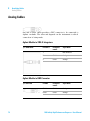
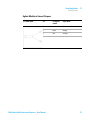
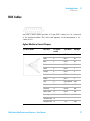
BCD Cables
One end of these cables provides a 15- pin BCD connector to be connected
to the Agilent modules. The other end depends on the instrument to be
connected to
Agilent Module to General Purpose
p/n G1351-81600
Wire Color
Pin Agilent
module
Signal Name
BCD Digit
Green
1
BCD 5
20
Violet
2
BCD 7
80
Blue
3
BCD 6
40
Yellow
4
BCD 4
10
Black
5
BCD 0
1
Orange
6
BCD 3
8
Red
7
BCD 2
4
Brown
8
BCD 1
2
Gray
9
Digital ground
Gray
Gray/pink
10
BCD 11
800
Red/blue
11
BCD 10
400
White/green
12
BCD 9
200
Brown/green
13
BCD 8
100
not connected
14
not connected
15
+5V
Low
1260 Infinity High Performance Degasser - User Manual
77
9
Identifying Cables
BCD Cables
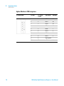
Agilent Module to 3396 Integrators
p/n 03396-60560
78
Pin 3396
Pin Agilent
module
Signal Name
BCD Digit
1
1
BCD 5
20
2
2
BCD 7
80
3
3
BCD 6
40
4
4
BCD 4
10
5
5
BCD0
1
6
6
BCD 3
8
7
7
BCD 2
4
8
8
BCD 1
2
9
9
Digital ground
NC
15
+5V
Low
1260 Infinity High Performance Degasser - User Manual
Identifying Cables
CAN Cable
9
CAN Cable
Both ends of this cable provide a modular plug to be connected to
Agilent modules CAN or LAN connectors.
CAN Cables
p/n
Description
5181-1516
CAN cable, Agilent module to module, 0.5 m
5181-1519
CAN cable, Agilent module to module, 1 m
LAN Cables
p/n
Description
5023-0203
Cross-over network cable, shielded, 3 m (for point to point connection)
5023-0202
Twisted pair network cable, shielded, 7 m (for point to point
connection)
1260 Infinity High Performance Degasser - User Manual
79
9
Identifying Cables
External Contact Cable
External Contact Cable
5
10
15
1
6
11
One end of this cable provides a 15- pin plug to be connected to
Agilent modules interface board. The other end is for general purpose.
Agilent Module Interface Board to general purposes
p/n G1103-61611
80
Color
Pin Agilent
module
Signal Name
White
1
EXT 1
Brown
2
EXT 1
Green
3
EXT 2
Yellow
4
EXT 2
Grey
5
EXT 3
Pink
6
EXT 3
Blue
7
EXT 4
Red
8
EXT 4
Black
9
Not connected
Violet
10
Not connected
Grey/pink
11
Not connected
Red/blue
12
Not connected
White/green
13
Not connected
Brown/green
14
Not connected
White/yellow
15
Not connected
1260 Infinity High Performance Degasser - User Manual
Identifying Cables
Agilent Module to PC
9
Agilent Module to PC
p/n
Description
G1530-60600
RS-232 cable, 2 m
RS232-61601
RS-232 cable, 2.5 m
Instrument to PC, 9-to-9 pin (female). This cable has special pin-out,
and is not compatible with connecting printers and plotters. It's also
called "Null Modem Cable" with full handshaking where the wiring is
made between pins 1-1, 2-3, 3-2, 4-6, 5-5, 6-4, 7-8, 8-7, 9-9.
5181-1561
RS-232 cable, 8 m
1260 Infinity High Performance Degasser - User Manual
81
9
Identifying Cables
Agilent 1200 Module to Printer
Agilent 1200 Module to Printer
82
p/n
Description
5181-1529
Cable Printer Serial & Parallel, is a SUB-D 9 pin female vs. Centronics
connector on the other end (NOT FOR FW UPDATE). For use with
G1323 Control Module.
1260 Infinity High Performance Degasser - User Manual
1260 Infinity High Performance Degasser - User Manual
10
Hardware Information
Operating Principle of the 1260 Infinity High Performance Degasser
Electrical Connections 85
Rear view of the module
Interfaces 86
Overview Interfaces
84
85
89
This chapter describes the degasser in more detail on hardware and
electronics.
Agilent Technologies
83
10 Hardware Information
Operating Principle of the 1260 Infinity High Performance Degasser
Operating Principle of the 1260 Infinity High Performance
Degasser
During initialization, the status indicator is amber and the degasser
vacuum pump tries to reach a target pressure below 146 mbar/hPa. If this
limit cannot be reached within 10 minutes, an error is thrown and the
status indicator gets red. As soon as the limit has been reached, which
typically happens after about 2 minutes, the pump goes to a continuous
regulation mode, where the pump tries to regulate to 100 mbar/hPa target
pressure. If this pressure limit cannot be reached, it is increased stepwise
to a maximum of 146 mbar and the status indicator goes to amber. If a
stable pressure between 100 mbar and 146 mbar max. can be kept, the
status indicator switches to off. If the maximum limit of 146 mbar is
exceeded, the status indicator goes to red and an error is thrown.
84
1260 Infinity High Performance Degasser - User Manual
Hardware Information
Electrical Connections
10
Electrical Connections
• The REMOTE connector may be used in combination with other
analytical instruments from Agilent Technologies if you want to use
features such as start, stop, common shut down, prepare, and so on.
• With the appropriate software, the RS- 232C connector may be used to
control the module from a computer through a RS- 232C connection.
This connector is activated and can be configured with the
configuration switch.
• The power input socket accepts a line voltage of 100 – 240 VAC ± 10 %
with a line frequency of 50 or 60 Hz. Maximum power consumption
varies by module. There is no voltage selector on your module because
the power supply has wide- ranging capability. There are no externally
accessible fuses, because automatic electronic fuses are implemented in
the power supply.
NOTE
Never use cables other than the ones supplied by Agilent Technologies to ensure proper
functionality and compliance with safety or EMC regulations.
Rear view of the module
EdlZg
GH"'('
GZbdiZ
AVWZa
Figure 15
Rear View of Degasser – Electrical Connections and Label
1260 Infinity High Performance Degasser - User Manual
85
10 Hardware Information
Interfaces
Interfaces
The Agilent 1200 Infinity Series modules provide the following interfaces:
Table 4
Agilent 1200 Infinity Series Interfaces
Module
CAN
LAN/BCD
(optional)
LAN
(on-board)
RS-232
Analog
APG
Remote
Special
G1310B Iso Pump
G1311B Quat Pump
G1311C Quat Pump VL
G1312B Bin Pump
K1312B Bin Pump Clinical Ed.
G1312C Bin Pump VL
1376A Cap Pump
G2226A Nano Pump
G5611A Bio-inert Quat Pump
2
Yes
No
Yes
1
Yes
G4220A/B Bin Pump
G4204A Quat Pump
2
No
Yes
Yes
No
Yes
CAN-DC- OUT for CAN
slaves
G1361A Prep Pump
2
Yes
No
Yes
No
Yes
CAN-DC- OUT for CAN
slaves
G1329B ALS
G2260A Prep ALS
2
Yes
No
Yes
No
Yes
THERMOSTAT for
G1330B/K1330B
G1364B FC-PS
G1364C FC-AS
G1364D FC-μS
G1367E HiP ALS
K1367E HiP ALS Clinical Ed.
G1377A HiP micro ALS
G2258A DL ALS
G5664A Bio-inert FC-AS
G5667A Bio-inert
Autosampler
2
Yes
No
Yes
No
Yes
THERMOSTAT for
G1330B/K1330B
CAN-DC- OUT for CAN
slaves
G4226A ALS
2
Yes
No
Yes
No
Yes
Pumps
Samplers
86
1260 Infinity High Performance Degasser - User Manual
Hardware Information
Interfaces
Table 4
10
Agilent 1200 Infinity Series Interfaces
Module
CAN
LAN/BCD
(optional)
LAN
(on-board)
RS-232
Analog
APG
Remote
Special
G1314B VWD VL
G1314C VWD VL+
2
Yes
No
Yes
1
Yes
G1314E/F VWD
K1314F Clinical Ed.
2
No
Yes
Yes
1
Yes
G4212A/B DAD
K4212B DAD Clinical Ed.
2
No
Yes
Yes
1
Yes
G1315C DAD VL+
G1365C MWD
G1315D DAD VL
G1365D MWD VL
2
No
Yes
Yes
2
Yes
G1321B FLD
K1321B FLD Clinical Ed.
G1321C FLD
2
Yes
No
Yes
2
Yes
G1362A RID
2
Yes
No
Yes
1
Yes
G4280A ELSD
No
No
No
Yes
Yes
Yes
EXT Contact
AUTOZERO
G1170A Valve Drive
2
No
No
No
No
No
1
G1316A/C TCC
K1316C TCC Clinical Ed.
2
No
No
Yes
No
Yes
G1322A DEG
K1322A DEG Clinical Ed.
No
No
No
No
No
Yes
G1379B DEG
No
No
No
Yes
No
Yes
G4225A DEG
K4225A DEG Clinical Ed.
No
No
No
Yes
No
Yes
Detectors
Others
1260 Infinity High Performance Degasser - User Manual
AUX
87
10 Hardware Information
Interfaces
Table 4
Agilent 1200 Infinity Series Interfaces
Module
CAN
LAN/BCD
(optional)
LAN
(on-board)
RS-232
Analog
APG
Remote
Special
G4227A Flex Cube
2
No
No
No
No
No
CAN-DC- OUT for CAN
slaves
1
G4240A CHIP CUBE
1
2
Yes
No
Yes
No
Yes
CAN-DC- OUT for CAN
slaves
THERMOSTAT for
G1330A/B (NOT
USED), K1330B
Requires a HOST module with on-board LAN (e.g. G4212A or G4220A with minimum firmware B.06.40 or C.06.40) or with additional G1369C LAN Card
NOTE
The detector (DAD/MWD/FLD/VWD/RID) is the preferred access point for control via
LAN. The inter-module communication is done via CAN.
• CAN connectors as interface to other modules
• LAN connector as interface to the control software
• RS- 232C as interface to a computer
• REMOTE connector as interface to other Agilent products
• Analog output connector(s) for signal output
88
1260 Infinity High Performance Degasser - User Manual
Hardware Information
Interfaces
10
Overview Interfaces
CAN
The CAN is inter- module communication interface. It is a 2- wire serial
bus system supporting high speed data communication and real- time
requirement.
LAN
The modules have either an interface slot for an LAN card (e.g. Agilent
G1369B/C LAN Interface) or they have an on- board LAN interface (e.g.
detectors G1315C/D DAD and G1365C/D MWD). This interface allows the
control of the module/system via a PC with the appropriate control
software. Some modules have neither on- board LAN nor an interface slot
for a LAN card (e.g. G1170A Valve Drive or G4227A Flex Cube). These are
hosted modules and require a Host module with firmware B.06.40 or later
or with additional G1369C LAN Card.
NOTE
If an Agilent detector (DAD/MWD/FLD/VWD/RID) is in the system, the LAN should be
connected to the DAD/MWD/FLD/VWD/RID (due to higher data load). If no Agilent
detector is part of the system, the LAN interface should be installed in the pump or
autosampler.
RS-232C (Serial)
The RS- 232C connector is used to control the module from a computer
through RS- 232C connection, using the appropriate software. This
connector can be configured with the configuration switch module at the
rear of the module. Refer to Communication Settings for RS- 232C.
NOTE
There is no configuration possible on main boards with on-board LAN. These are
pre-configured for
• 19200 baud,
• 8 data bit with no parity and
• one start bit and one stop bit are always used (not selectable).
1260 Infinity High Performance Degasser - User Manual
89
10 Hardware Information
Interfaces
The RS- 232C is designed as DCE (data communication equipment) with a
9- pin male SUB- D type connector. The pins are defined as:
Table 5
RS-232C Connection Table
Pin
Direction
Function
1
In
DCD
2
In
RxD
3
Out
TxD
4
Out
DTR
5
Ground
6
In
DSR
7
Out
RTS
8
In
CTS
9
In
RI
>chigjbZci
BVaZ
Figure 16
E8
;ZbVaZ
;ZbVaZ BVaZ
RS-232 Cable
Analog Signal Output
The analog signal output can be distributed to a recording device. For
details refer to the description of the module’s main board.
90
1260 Infinity High Performance Degasser - User Manual
Hardware Information
Interfaces
10
APG Remote
The APG Remote connector may be used in combination with other
analytical instruments from Agilent Technologies if you want to use
features as common shut down, prepare, and so on.
Remote control allows easy connection between single instruments or
systems to ensure coordinated analysis with simple coupling requirements.
The subminiature D connector is used. The module provides one remote
connector which is inputs/outputs (wired- or technique).
To provide maximum safety within a distributed analysis system, one line
is dedicated to SHUT DOWN the system’s critical parts in case any module
detects a serious problem. To detect whether all participating modules are
switched on or properly powered, one line is defined to summarize the
POWER ON state of all connected modules. Control of analysis is
maintained by signal readiness READY for next analysis, followed by START
of run and optional STOP of run triggered on the respective lines. In
addition PREPARE and START REQUEST may be issued. The signal levels are
defined as:
• standard TTL levels (0 V is logic true, + 5.0 V is false),
• fan- out is 10,
• input load is 2.2 kOhm against + 5.0 V, and
• output are open collector type, inputs/outputs (wired- or technique).
NOTE
All common TTL circuits operate with a 5 V power supply. A TTL signal is defined as "low"
or L when between 0 V and 0.8 V and "high" or H when between 2.0 V and 5.0 V (with
respect to the ground terminal).
1260 Infinity High Performance Degasser - User Manual
91
10 Hardware Information
Interfaces
Table 6
Remote Signal Distribution
Pin
Signal
Description
1
DGND
Digital ground
2
PREPARE
(L) Request to prepare for analysis (for example, calibration, detector
lamp on). Receiver is any module performing pre-analysis activities.
3
START
(L) Request to start run / timetable. Receiver is any module
performing run-time controlled activities.
4
SHUT DOWN
(L) System has serious problem (for example, leak: stops pump).
Receiver is any module capable to reduce safety risk.
5
Not used
6
POWER ON
(H) All modules connected to system are switched on. Receiver is
any module relying on operation of others.
7
READY
(H) System is ready for next analysis. Receiver is any sequence
controller.
8
STOP
(L) Request to reach system ready state as soon as possible (for
example, stop run, abort or finish and stop injection). Receiver is any
module performing run-time controlled activities.
9
START REQUEST
(L) Request to start injection cycle (for example, by start key on any
module). Receiver is the autosampler.
Special Interfaces
There is no special interface for this module.
92
1260 Infinity High Performance Degasser - User Manual
1260 Infinity High Performance Degasser - User Manual
11
Appendix
General Safety Information
94
The Waste Electrical and Electronic Equipment (WEEE) Directive
(2002/96/EC) 97
Radio Interference
Sound Emission
98
99
Agilent Technologies on Internet
100
This chapter provides addition information on safety, legal and web.
Agilent Technologies
93
11 Appendix
General Safety Information
General Safety Information
General Safety Information
The following general safety precautions must be observed during all
phases of operation, service, and repair of this instrument. Failure to
comply with these precautions or with specific warnings elsewhere in this
manual violates safety standards of design, manufacture, and intended use
of the instrument. Agilent Technologies assumes no liability for the
customer’s failure to comply with these requirements.
WA R N I N G
Ensure the proper usage of the equipment.
The protection provided by the equipment may be impaired.
➔ The operator of this instrument is advised to use the equipment in a manner as
specified in this manual.
Safety Standards
This is a Safety Class I instrument (provided with terminal for protective
earthing) and has been manufactured and tested according to
international safety standards.
94
1260 Infinity High Performance Degasser - User Manual
Appendix
General Safety Information
11
Operation
Before applying power, comply with the installation section. Additionally
the following must be observed.
Do not remove instrument covers when operating. Before the instrument is
switched on, all protective earth terminals, extension cords,
auto- transformers, and devices connected to it must be connected to a
protective earth via a ground socket. Any interruption of the protective
earth grounding will cause a potential shock hazard that could result in
serious personal injury. Whenever it is likely that the protection has been
impaired, the instrument must be made inoperative and be secured against
any intended operation.
Make sure that only fuses with the required rated current and of the
specified type (normal blow, time delay, and so on) are used for
replacement. The use of repaired fuses and the short- circuiting of fuse
holders must be avoided.
Some adjustments described in the manual, are made with power supplied
to the instrument, and protective covers removed. Energy available at
many points may, if contacted, result in personal injury.
Any adjustment, maintenance, and repair of the opened instrument under
voltage should be avoided whenever possible. When inevitable, this has to
be carried out by a skilled person who is aware of the hazard involved. Do
not attempt internal service or adjustment unless another person, capable
of rendering first aid and resuscitation, is present. Do not replace
components with power cable connected.
Do not operate the instrument in the presence of flammable gases or
fumes. Operation of any electrical instrument in such an environment
constitutes a definite safety hazard.
Do not install substitute parts or make any unauthorized modification to
the instrument.
Capacitors inside the instrument may still be charged, even though the
instrument has been disconnected from its source of supply. Dangerous
voltages, capable of causing serious personal injury, are present in this
instrument. Use extreme caution when handling, testing and adjusting.
When working with solvents, observe appropriate safety procedures (for
example, goggles, safety gloves and protective clothing) as described in the
material handling and safety data sheet by the solvent vendor, especially
when toxic or hazardous solvents are used.
1260 Infinity High Performance Degasser - User Manual
95
11 Appendix
General Safety Information
Safety Symbols
Table 7
Safety Symbols
Symbol
Description
The apparatus is marked with this symbol when the user should refer to
the instruction manual in order to protect risk of harm to the operator and
to protect the apparatus against damage.
Indicates dangerous voltages.
Indicates a protected ground terminal.
Indicates eye damage may result from directly viewing the light produced
by the deuterium lamp used in this product.
The apparatus is marked with this symbol when hot surfaces are available
and the user should not touch it when heated up.
WA R N I N G
A WARNING
alerts you to situations that could cause physical injury or death.
➔ Do not proceed beyond a warning until you have fully understood and met the
indicated conditions.
CAUTION
A CAUTION
alerts you to situations that could cause loss of data, or damage of equipment.
➔ Do not proceed beyond a caution until you have fully understood and met the
indicated conditions.
96
1260 Infinity High Performance Degasser - User Manual
Appendix
The Waste Electrical and Electronic Equipment (WEEE) Directive (2002/96/EC)
11
The Waste Electrical and Electronic Equipment (WEEE) Directive
(2002/96/EC)
Abstract
The Waste Electrical and Electronic Equipment (WEEE) Directive
(2002/96/EC), adopted by EU Commission on 13 February 2003, is
introducing producer responsibility on all electric and electronic
appliances starting with 13 August 2005.
NOTE
This product complies with the WEEE Directive (2002/96/EC) marking requirements. The
affixed label indicates that you must not discard this electrical/electronic product in
domestic household waste.
Product Category:
With reference to the equipment types in the WEEE Directive Annex I, this product is
classed as a Monitoring and Control Instrumentation product.
NOTE
Do not dispose off in domestic household waste
To return unwanted products, contact your local Agilent office, or see www.agilent.com for
more information.
1260 Infinity High Performance Degasser - User Manual
97
11 Appendix
Radio Interference
Radio Interference
Cables supplied by Agilent Technologies are screened to provide optimized
protection against radio interference. All cables are in compliance with
safety or EMC regulations.
Test and Measurement
If test and measurement equipment is operated with unscreened cables, or
used for measurements on open set- ups, the user has to assure that under
operating conditions the radio interference limits are still met within the
premises.
98
1260 Infinity High Performance Degasser - User Manual
Appendix
Sound Emission
11
Sound Emission
Manufacturer’s Declaration
This statement is provided to comply with the requirements of the
German Sound Emission Directive of 18 January 1991.
This product has a sound pressure emission (at the operator position)
< 70 dB.
• Sound Pressure Lp < 70 dB (A)
• At Operator Position
• Normal Operation
• According to ISO 7779:1988/EN 27779/1991 (Type Test)
1260 Infinity High Performance Degasser - User Manual
99
11 Appendix
Agilent Technologies on Internet
Agilent Technologies on Internet
For the latest information on products and services visit our worldwide
web site on the Internet at:
http://www.agilent.com
100
1260 Infinity High Performance Degasser - User Manual
Index
Index
A
accessory kit 68
Agilent
on internet 100
algae growth 42
ambient non-operating temperature 17
ambient operating temperature 17
analog signal 90
analog
cable 72
APG remote connector 29
apg remote 91
B
BCD
cable 77
bench space 16
C
cable
analog 72
BCD 77
CAN 79, 29
external contact 80
LAN 79
power 55
remote 74, 55
RS-232 81
cables
analog 70
BCD 70
CAN 71
external contact 71
LAN 71
overview 70
remote 70
RS-232 71
CAN cable 29
CAN
cable 79
changing solvents 34, 36
cleaning 61
condensation 16
configuration
one stack 22, 22
control assembly 8
cover 66
D
defect on arrival 20
delivery checklist 20
dimensions 17
E
electrical connections
descriptions of 85
electronic waste 97
error state 56, 56
exchanging
solenoid valve 63
external contact
cable 80
fuse
55, 63
H
hardware symptoms 55
highest injection precision 41
highest retention time reproducibility
humidity 17
41
I
information
on sound emission 99
installation
bench space 16
interfaces 86
internet 100
introduction to the degasser 8
L
lamps
off, degasser appears dead 55
status indicator is red 56, 56
status indicator is yellow, vacuum
pump not running 56
LAN
cable 79
line frequency 17
line voltage 17
M
F
flow connections 31, 31
flow rate 18
frequency range 17
1260 Infinity High Performance Degasser - User Manual
main cover, assembling 62
materials in contact with solvent
maximum flow rate 18
maximum sensitivity 41
18
101
Index
N
non-operating altitude 17
non-operating temperature 17
number of channels 18
O
operating Altitude 17
operating temperature 17
optimization
stack configuration 21
P
packaging
damaged 20
parts
accessory kit 68
cover 66
damaged 20
missing 20
performance specifications 18
pH range 18
physical specifications 17
power cable 55
power consideration 14
power consumption 17
power cords 15
power supply 63
power switch 29
pressure sensor 8
priming
with a pump 35
with a syringe 35
principle of operation 8
R
radio interference 98
remote cable 55
remote
102
cable
RS-232C
cable
W
74
81
S
safety class I 94
safety
general information 94
standards 17
symbols 96
site requirements
power cords 15
solenoid valve 63
solvent filters
checking 42
cleaning 42
prevent blocking 42
sound emission 99
special interfaces 92
specification
performance specifications 18
physical 17
status indicator 54, 56, 56, 56
syringe adapter 36
system setup and installation
optimizing stack configuration 21
waste
electrical and electronic
equipment 97
WEEE directive 97
weight 17
T
transportation 37
troubleshooting
status indicators
53
V
vacuum pump 8
voltage range 17
voltage selector 63
volume per channel 18
1260 Infinity High Performance Degasser - User Manual
Index
1260 Infinity High Performance Degasser - User Manual
103
www.agilent.com
In This Book
This manual contains information about the
Agilent 1260 Infinity High Performance
Degasser (G4225A). The manual describes the
following:
• introduction,
• site requirements and specifications,
• installing the degasser,
• using the degasser,
• troubleshooting and diagnostics,
• maintenance,
• parts for maintenance,
• identifying cables,
• appendix.
© Agilent Technologies 2011-2013, 2014
Printed in Germany
02/2014
*G4225-90002*
*G4225-90002*
G4225-90002
Agilent Technologies