1
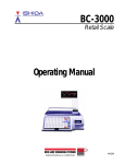
Counter Scale Printer
SERVICE MANUAL
Lb
WARNING
• Do not carry out installation, operation, service,
or maintenance until thoroughly understanding
the contents of this manual.
• Keep this manual available at all times for installation, operation, service, and maintenance.
Manual No. 0145A
ISHIDA CO., LTD.
You can help improve this manual by
calling attention to errors and by
recommending improvements. Please
convey your comments to the nearest
Ishida Company regional representative.
Thank you!
Copyright 2001 by Ishida Co., Ltd. All Rights Reserved.
No part of this manual may be reproduced in any form, by mimeograph or any other means,
without written permission of the publisher.
SAFETY CONSIDERATIONS
To ensure safe operation, the general safety considerations below must be
followed.
Grounding
This instrument is a Class 1 device which requires protective grounding for safe
operation.
To avoid potential shock hazards, a protective grounding conductor for the
instrument must be securely connected to the main grounding provision by
qualified service personnel.
Do not remove covers or enclosures
To avoid personal injury and shock, do not open or remove any covers or
enclosures of the instrument unless specified in the manual.
Do not perform unspecified maintenance
For your personal safety, do not perform any maintenance procedures which
are not specified in the manual.
Disconnect power supply before servicing
To ensure your personal safety, disconnect the power supply before servicing.
IMPORTANT INFORMATION
CONFORMITY TO EC COUNCIL DIRECTIVES
The instrument is designed in accordance with the following directives.
●
Non-automatic Weighing Instrument Directive 90/384/EEC, amended by 93/
68/EEC
Compliance was checked using the following standards:
EN45501 ‘Metrological aspects of non-automatic weighing instruments’
●
EMC Directive 89/336/EEC amended by 91/263/EEC, 92/32/EEC and 93/68/
EEC.
Compliance was checked using the following standards:
EN55011 ‘Limits and methods of measurement of radio disturbance
characteristics of industrial, scientific and medical (ISM) radiofrequency equipment, Group 1, Class B’
To ensure conformity, any unauthorized modification and/or service on the
instrument constitutes a repeal of conformity.
Note: Compliance with these directives is only necessary in EC countries.
ASTRA • Service Manual • Manual No. 0145A
Safety Considerations
CONTENTS
Chapter 1 Precautions
1.1 Cautions for Installation ................................................................................................. 2
1.1.1 Installation Areas ........................................................................................................ 2
1.1.2 Power Supply ............................................................................................................. 2
1.1.3 Level Adjustment ........................................................................................................ 3
1.1.4 Handling Precautions ................................................................................................. 3
Chapter 2 Product Overview
2.1 Appearance ...................................................................................................................... 6
2.2 Display (lb) ....................................................................................................................... 6
2.3 Operation Key Sheet ....................................................................................................... 7
2.3.1 Basic Function Keys ................................................................................................... 7
2.4 Program Key Sheet ......................................................................................................... 8
2.5 Loading/Unloading Label Roll ........................................................................................ 9
2.5.1 Loading ...................................................................................................................... 9
2.5.2 Unloading ................................................................................................................. 10
2.6 ASTRA Hardware Specifications ................................................................................. 11
Chapter 3 Setup Mode
3.1 Setup Mode Entry .......................................................................................................... 14
3.2 Label Print (b01-01) ....................................................................................................... 15
3.3 Label Format (b01-02) .................................................................................................... 17
3.4 POS Code (b02) .............................................................................................................. 20
3.5 Bar Code (b03) ............................................................................................................... 22
3.6 Default Setup (b04) ........................................................................................................ 23
3.7 Total (b05) ........................................................................................................................ 24
3.8 Forced Tare (b06) ............................................................................................................ 25
3.9 Open Price Setup (b07) .................................................................................................. 26
Chapter 4 Test Mode
4.1 Test Mode Entry ............................................................................................................ 28
4.2 Hardware Test ................................................................................................................ 29
4.2.1 A/D Calibration (C01-01) .......................................................................................... 29
4.2.2 Key Check (C01-02) ................................................................................................. 30
4.2.3 Display Check (C01-03) ........................................................................................... 31
4.2.4 RS-232C Check (C01-04) ........................................................................................ 32
4.2.5 PROM Number Check (C01-05) .............................................................................. 33
Contents
ASTRA • Service Manual • Manual No. 0145A
4.3 RAM Clear (C02) ............................................................................................................ 34
4.4 Print Head (C03).............................................................................................................. 36
4.5 Sensor Check (C04) ...................................................................................................... 38
4.6 Total Memory (C05) ........................................................................................................ 39
4.7 ROM Switch (C06)........................................................................................................... 40
Chapter 5 Registration Mode
5.1 Registration Mode Entry ............................................................................................... 44
5.2 PLU Programming (P01) ............................................................................................... 45
5.2.1 Deleting a PLU ......................................................................................................... 49
5.3 PLU Name (P02) ............................................................................................................. 50
5.4 Price Change (P03) ........................................................................................................ 51
5.5 Preset Keys (P04) .......................................................................................................... 52
5.5.1 Preset Keys – PLU and Tare Values ......................................................................... 52
5.5.2 Preset Function Keys ............................................................................................... 54
5.5.3 Deleting All Preset Keys ........................................................................................... 56
5.6 Shop Name/Address (P05) ............................................................................................ 57
5.7 Date/Time (P06)............................................................................................................... 58
5.8 Extra Message (P07) ...................................................................................................... 59
5.9 Default PLU (P08) ........................................................................................................... 60
5.10 PLU List Print (P09) ....................................................................................................... 61
5.11 Communication (Sending) (P10-01) ............................................................................. 62
5.12 Communication (Receiving) (P10-02) .......................................................................... 63
5.13 Nutrition (P11) ................................................................................................................ 64
Chapter 6 Text Editing
6.1 Edit Keys ........................................................................................................................ 70
6.2 Key Definition ................................................................................................................ 70
6.3 Edit Display .................................................................................................................... 71
6.4 Edit Examples ................................................................................................................ 71
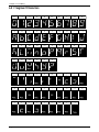
6.5 7-Segment Characters .................................................................................................. 72
6.6 Wordwrap Function ....................................................................................................... 73
6.7 Selecting Italic Character Fonts .................................................................................... 73
6.8 Character Size ................................................................................................................ 74
Chapter 7 Normal Mode
7.1 Normal Mode Operations .............................................................................................. 76
7.2 Tare Weight Subtraction ................................................................................................ 78
7.3 Preset Function Keys .................................................................................................... 80
ASTRA • Service Manual • Manual No. 0145A
Contents
Chapter 8 Total Mode
8.1 Total Mode Operations .................................................................................................. 82
Chapter 9 Subtraction Mode
9.1 Subtraction Mode Operations ...................................................................................... 86
Chapter 10 Troubleshooting
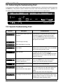
10.1 Before Using the Troubleshooting Chart .................................................................. 90
10.2 Operator Troubleshooting Chart ................................................................................ 90
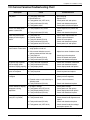
10.3 Service Personnel Troubleshooting Chart ................................................................ 91
Chapter 11 Hardware Structure
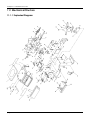
11.1 Mechanical Structure .................................................................................................. 94
11.1.1 Exploded Diagram .................................................................................................. 94
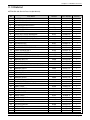
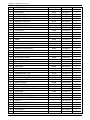
11.1.2 Parts List ................................................................................................................. 95
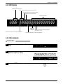
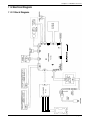
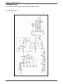
11.2 Electrical Diagram ....................................................................................................... 97
11.2.1 Block Digram........................................................................................................... 97
11.2.2 Circuit Boards ......................................................................................................... 98
Chapter 12 Maintenance
12.1 Daily Maintenance ..................................................................................................... 102
12.2 Setting the Power Supply Unit (LSF100-24S) ......................................................... 103
12.3 Parts Replacement ................................................................................................... 104
12.3.1 Replacing the Thermal Head ................................................................................ 104
12.3.2 Replacing the Load Cell ........................................................................................ 105
12.3.3 Replacing the Print Roller ..................................................................................... 108
12.3.4 Replacing the Keysheet ........................................................................................ 110
Appendix
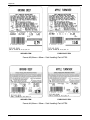
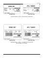
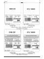
A.1
Sample Labels ........................................................................................................... 114
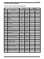
A.2
Label Format Worksheets ........................................................................................ 119
A.3
Communication Cable Wiring Diagram ................................................................... 135
Contents
ASTRA • Service Manual • Manual No. 0145A
Chapter 1. Precautions
CHAPTER
1
PRECAUTIONS
1.1 Cautions for Installation .......................... 2
1.1.1 Installation Areas .................................. 2
1.1.2 Power Supply ....................................... 2
1.1.3 Level Adjustment .................................. 3
1.1.4 Handling Precautions ........................... 3
ASTRA • Service Manual • Manual No. 0145A
page 1
Chapter 1. Precautions
1.1 Cautions for Installation
1.1.1 Installation Areas
Avoid the following areas when installing the machine.
●
Areas subject to high
temperatures or high humidity
●
Areas subject to excessive
vibration or unstable surfaces
●
Areas subject to a lot of dust or
dirt
●
Areas exposed to direct sunlight
●
Areas exposed to direct cold air
●
●
Areas where water or other
liquids are easily spilled on the
machine
●
Areas subject to low
temperatures
Areas with large voltage
fluctuations
1.1.2 Power Supply
●
Use the appropirate voltage after referring to the specification
plate located on the machine
●
Use a dedicated power source
(Voltage fluctuation can cause the machine to malfunction)
●
Do not stand on, or place heavy objects on the power cord
(If the cord is damaged and still used, it may cause an accident or other
problems)
page 2
ASTRA • Service Manual • Manual No. 0145A
Chapter 1. Precautions
Unlevel
➜
LEVEL
USE
IN
USE
IN
E
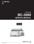
Adjust the machine to a level position using the four
level adjusters, located on the bottom of the machine,
until the bubble is completely centered in the round level
indicator.
E
●
ST
MU B
Always ensure that the machine is level.
If the machine is not level, weighing may not be
accurate.
ST
MU B
●
LEVEL
1.1.3 Level Adjustment
Level
1.1.4 Handling Precautions
●
Only trained service personnel
should disassemble the machine
as directed in this manual.
●
When cleaning the machine, only
use a soft dry cloth or a cloth
wetted with a neutral cleanser.
Never use thinner or other volatile
liquids.
ASTRA • Service Manual • Manual No. 0145A
●
Do not drop or apply strong jolts
to the machine.
page 3
Chapter 1. Precautions
page 4
ASTRA • Service Manual • Manual No. 0145A
Chapter 2. Product Overview
CHAPTER
2
PRODUCT OVERVIEW
2.1 Appearance ............................................ 6
2.2 Display ...................................................... 6
2.3 Operation Key Sheet .............................. 7
2.3.1 Basic Function Keys ............................. 7
2.4 Program Key Sheet ................................. 8
2.5 Loading/Unloading Label Roll ............... 9
2.5.1 Loading ................................................. 9
2.5.2 Unloading ........................................... 10
2.6 Astra Hardware Specifications ............ 11
ASTRA • Service Manual • Manual No. 0145A
page 5
Chapter 2. Product Overview
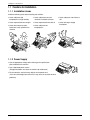
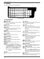
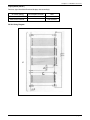
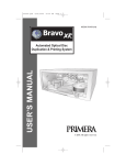
2.1 Appearance
Power switch
Side view
AC power
Weigh platter
Display
Level adjuster
Key sheet
Level
Label printer
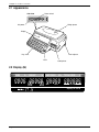
2.2 Display (lb)
TARE
lb
WEIGHT
ZERO
lb
NET
$/lb
UNIT PRICE
SAVE
AUTO
TOTAL PRICE
$
PLU
Capacity 30 × 0.01 lb
page 6
ASTRA • Service Manual • Manual No. 0145A
Chapter 2. Product Overview
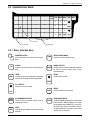
2.3 Operation Key Sheet
AUTO DATE MODE ZERO
MANU
7
8
9
4
5
6
1
2
3
0
CLR
TARE
FEED
RESET
PRINT
PLU
Preset keys
Sheet stopper
Handling tab
2.3.1 Basic Function Keys
0
9
CLR
TARE
NUMERIC ENTRY
Keys 0 through 9 are used to enter numeric
data.
ZERO
CLEAR
Used to cancel incorrectly entered numeric
data.
MODE
TARE
Used to set the tare weight to be subtracted
from the total weight on the weigh platter.
ZERO ADJUSTMENT
Used to reset the weight to zero.
MODE SELECT
Used to return to normal operation mode or
to enter a desired mode after 4 digit
password entry.
PRINT
Used to issue a label.
PRINT
PLU SELECT
Used to access PLU data.
RESET
PLU
AUTO
MANU
AUTO/MANUAL SELECT
Used to select automatic label issue or
manual label issue.
FEED
FEED
Used to advance labels to the correct printing
position.
ASTRA • Service Manual • Manual No. 0145A
DATE
RESET
Used to initialize the machine.
TEMPORARY DATE
Used to temporarily change the current date
of the machine. After recalling a PLU, enter
the temporary date (MMDDYY) and press
the DATE key. Enter the number 0 to turn
all date printing off. The date is reset when
another PLU is selected.
page 7
Chapter 2. Product Overview
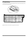
2.4 Program Key Sheet
The Program Key Sheet is located underneath the Operation Key Sheet. It can be accessed by lifting up the cover
film and removing the Operation Key Sheet.
Key sheet
Cover film
Q
!
A
W
“
S
SYMBOL
FUNCTION
Z
#
D
@
=
LOWER
CASE
E
,
R
$
PLU
LIST
&
U
J
H
}
V
B
SIZE
Ñ
END
←
‘
I
N
EDIT
PLU
Ç
↑
↓
(
K
+
M
O
)
L
;
*
INSERT COPY SPACE
PLU PRICE
FILE CHANGE
Y
{
]
C
.
%
G
F
[
X
T
:
BACK
SPACE
DELETE NEW
LINE
→
ENTER
P
_
MODE ZERO
7
8
9
4
5
6
1
2
3
0
CLR
TARE
FEED
RESET
PRINT
PLU
Note: Refer to Section 6.2 of this manual for an explaination of the key functions.
page 8
ASTRA • Service Manual • Manual No. 0145A
Chapter 2. Product Overview
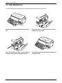
2.5 Loading/Unloading Label Roll
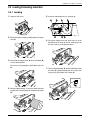
2.5.1 Loading
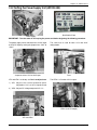
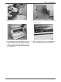
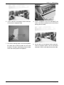
1. Open the side cover.
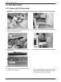
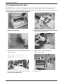
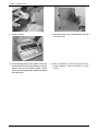
5. Insert the label paper from (1) through (4).
C
D
A
B
4
2. Release the printer head by pushing down the release
lever (D).
G
E
F
6. Pull up the stopper lever (A), then slide it in or out
depending on the width of the roll, making sure not
to move it too far in and bind the labels.
3. Check that the stopper lever (A) of the roll holder (B)
is in the down position.
If the lever is in an up position, push down until it lies
flat.
7. Turn the winding bobbin (E) counter-clockwise so that
the hook (G) is positioned up, push in lever (F), then
insert the tip of the paper in the hook (G).
F
4. Remove approximately 12 inches of labels from the
end of the roll. Load the label roll around the roll holder
(B).
ASTRA • Service Manual • Manual No. 0145A
page 9
Chapter 2. Product Overview
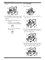
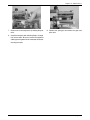
8. Replace the printer head by pushing down the lock
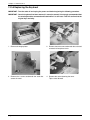
2.5.2 Unloading
lever (C).
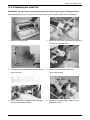
1. Open the side cover.
9. Press the FEED key on the key sheet once or twice
in order to securely turn the paper around the winding
bobbin (E).
2. Release the printer head by pushing down the
release lever (D).
Note: Check that the label printing position is
properly set.
If not properly set, press the FEED key
until it reaches the proper printing position.
FEED
Press the Clear key to remove any
error messages.
CLR
3. Pull the lever (F) outwards to loosen the paper wound
around the winding bobbin (E), then remove the
paper from the winding bobbin.
4. Push down the stopper lever (A) of the roll holder
(B) to make it straight, then remove the label roll from
the path ((1) through (4)) and the roll holder (B).
page 10
ASTRA • Service Manual • Manual No. 0145A
Chapter 2. Product Overview
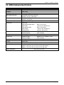
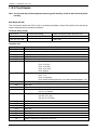
2.6 ASTRA Hardware Specifications
ASTRA
Accuracy
1/3000 Single Range
Capacity
30 lb (15 kg)
Min. Graduation
0.01 lb (0.005 kg)
Main Body Dimension
15.75" (W) × 16.34" (D) × 6.50" (H)
400 (W) × 415 (D) × 165 (H) mm
Platter Size
14.02" (W) × 9.21" (D)
356 (W) × 234 (D) mm
Weight
Approx. 20.9 lb (9.5 kg)
Printer Unit
Side-Load
Label backing paper width
Label width
Label printing width
Label length
Printing speed
Max. 2.64" (67 mm)
1.50" to 2.52" (38 to 64 mm)
Max. 2.36" (60 mm)
1.18" to 3.35" (30 to 85 mm)
3.15"/sec. (80 mm/sec.)
Label Roll Dimension
Inside diameter
Outside diameter
1.57" (40 mm)
3.94" (100 mm)
Sensor
Label (Gap) sensor
Display Unit
Number of digits
Character height
Keyboard
64 keys in total. 44 preset keys store up to 88 preset items.
System
Stand alone
Input/Output
RS232C (for PLU/Label editor)
Item Memory
256KB
Approx. 2000 PLUs (Avg. 30 char. per PLU) without total
Approx. 1500 PLUs (Avg. 30 char. per PLU) with total
Safety Regulations
ASTRA • Service Manual • Manual No. 0145A
Weight 5, U/P 5, Amount 6, Tare 4
0.42" (10.6 mm)
UL, C-UL, CE, C-Tick
page 11
Chapter 2. Product Overview
page 12
ASTRA • Service Manual • Manual No. 0145A
Chapter 3. Setup Mode
CHAPTER
3
SETUP MODE
3.1 Setup Mode Entry ................................. 14
3.2 Label Print (b01-01) ............................... 15
3.3 Label Format (b01-02) .......................... 17
3.4 POS Code (b02) .................................... 20
3.5 Bar Code (b03) ..................................... 22
3.6 Default Setup (b04) ............................... 23
3.7 Total (b05) .............................................. 24
3.8 Forced Tare (b06) .................................. 25
3.9 Open Price Setup (b07) ....................... 26
ASTRA • Service Manual • Manual No. 0145A
page 13
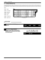
Chapter 3. Setup Mode
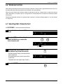
3.1 Setup Mode Entry
Setup Mode operations (b00) are required when initially setting up the basic functions of the Astra. When performing
these operations, use the Program Key Sheet (located underneath the Operation Key Sheet) to set up the following
items.
• b01 :
• b02 :
• b03 :
• b04 :
• b05 :
• b06 :
• b07 :
Label
POS Code
Bar Code
Default
Total
Forced Tare
Q
!
A
W
“
S
SYMBOL
FUNCTION
Z
#
D
@
=
LOWER
CASE
E
,
R
$
PLU
LIST
&
‘
J
H
V
U
}
B
I
(
K
+
EDIT
PLU
SIZE
Ñ
END
←
)
L
:
P
_
MODE ZERO
7
8
9
M
BACK
SPACE
4
5
6
↑
DELETE
NEW
LINE
1
2
3
↓
→
ENTER
0
CLR
TARE
N
Ç
O
;
*
INSERT COPY SPACE
PRICE
PLU
FILE CHANGE
Y
{
]
C
.
%
G
F
[
X
T
FEED
RESET
PRINT
PLU
Open Price
PROCEDURES
1 Ensure that the Initial Display
appears.
ZERO
2 Key in the 4 digit password
(default value: 6000) and press the
MODE key. The Setup mode display
will then appear.
page 14
6
0
0
0
➜
MODE
ASTRA • Service Manual • Manual No. 0145A
Chapter 3. Setup Mode
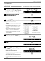
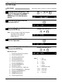
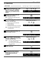
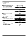
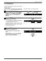
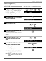
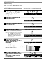
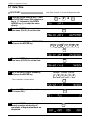
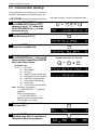
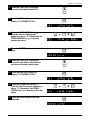
3.2 Label Print
NOTE
PROCEDURES
Note: Refer to page 14, Section 3.1 to enter the Setup Mode.
1
➜
➝
➝
➝
or
➝
1 Press the DOWN ARROW key ( ) until
the Label menu (b01) appears or key
in “1” followed by the DOWN ARROW
key ( ) to enter the menu directly.
2 Press the ENTER key to enter the
Label Print menu (b01-01).
ENTER
3 Press the ENTER key to enter the
Label Print Format menu.
ENTER
• This menu is used to set the label print format
number.
• Standard label format numbers are “1” to “5”.
Formats 6, 7, and 8 are available in some
versions.
• When no label format number is set, label
format “1” is set as the default number.
• Additional label format numbers “20” to “99”
may be available.
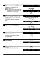
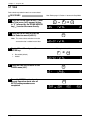
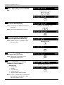
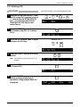
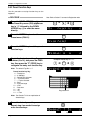
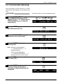
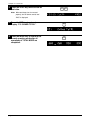
4 Key in the required label print format
number and press the ENTER key.
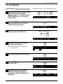
The Standard formats are:
6* – 64mm × 59mm
Extended Text
1 – 60mm × 44mm
2 – 64mm × 47mm
3 – 64mm × 85mm
Safe Handling
7* – 64mm × 85mm
Extended Text
4 – 64mm × 59mm
Safe Handling
8* – 64mm × 85mm
Reduced S.H.
5 – 64mm × 37mm
Non-barcode
*Not available in all versions
Example: Set label print format as “2”
2
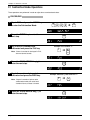
5 Press the ENTER key to set the label
length.6
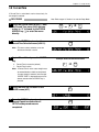
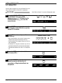
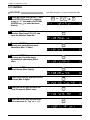
6 Key in the required label length and
label gap (XX.X mm), and then press
the ENTER key.
➜
ENTER
ENTER
Example: Set the label length to 45.5 mm.
4
5
5
• 85mm is the maximum label size.
• Measure this distance from the top of one label
to the top of the next label.
ENTER
• Butt-cut labels may not be used in the Astra.
• Continous strip labels may not be used in the
Astra.
ASTRA • Service Manual • Manual No. 0145A
page 15
Chapter 3. Setup Mode
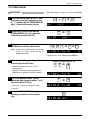
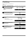
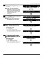
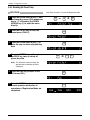
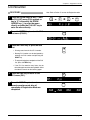
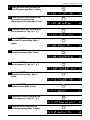
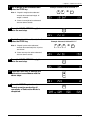
7 Key in the required label width
(XX.X mm) and press the ENTER key.
•If the label width is 60mm or larger, use
the default value of “0.0”.
Example: Set the label width to 55.2 mm
5
5
2
Note: This setting is used by the Astra for word
wrapping when new PLU descriptions and
Extra Messages are programmed.
ENTER
8 Key in the required distance
(XX.X mm) between the label sensor
and thermal print head and press the
ENTER key.
Example: Set the distance to 74.8 mm
7
Use this step to adjust print position on the
label.
• Increasing this value raises the printing on
the label.
4
8
ENTER
9 Key in the PLU number for test
printing and press the ENTER key.
Example: PLU “1”
1
➜
ENTER
10 Press the PRINT key for test print to
confirm the label format.
If necessary, return to Step b01-01-04 to
adjust print position.
PRINT
11 Press the END key to return to the
Label menu (b01).
END
12 Press the MODE key to return to
the Normal Operation mode after
all SETUP mode procedures are
completed.
MODE
ZERO
page 16
ASTRA • Service Manual • Manual No. 0145A
Chapter 3. Setup Mode
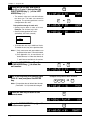
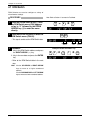
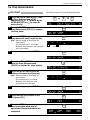
3.3 Label Format
PROCEDURES
Note: Refer to page 14, Section 3.1 to enter the Setup Mode.
➝
➜
1
or
➝
➝
1 Press the DOWN ARROW key ( ) until
the Label menu (b01) appears or key
in “1” followed by the DOWN ARROW
key ( ) to enter the menu directly.
➝
➝
ENTER
3 Enter the password and press the
ENTER key to edit the label format.
Note: To prevent accidental changes to the label
format, this step is protected by an
additional password.
4 Key in the label format number to be
set and press the PLU key.
4
1
4
1
➜
SIZE
➜
ENTER
The password is “4141” followed by the SIZE key.
Example: Set label format as “20”
2
0
• Additional formats from “20” to “99” are
programmable.
(Number of label formats to be programmed
depends on the amount of available memory.)
5 Key in the desired format number
(standard label format number, 1 to 5)
and press the COPY key.
➜
➝
2 Press the ENTER key and then the
DOWN ARROW key ( ) to enter the
Label Format menu (b01-02).
➜
PLU
1
➜
COPY
• Formats 6, 7, and 8 are available in some
versions.
fi
➝
➝
6 Press the DOWN ARROW key ( ) to
set the print position of each print
unit.
6
ASTRA • Service Manual • Manual No. 0145A
page 17
Chapter 3. Setup Mode
7 Press the ENTER key, and select X
axis (0) or Y axis (1) using either the
RIGHT ARROW key ( ) or the LEFT
ARROW key (➝ ).
ENTER
➝
• The numeric value set in unit #0 indicates
the label size. The label size cannot be
changed. The printing positions can be
changed within this area.
Unit #
➝
Print position change for each unit
• Setting can be done in units of 0.1mm.
Example: For 20.0mm, key in 200.
• Set the printing position for X-axis
(horizontal), and Y-axis (vertical)
Label size
➝
or
X axis
Y axis
X
123456
Y
• To disable the unit, key in 9999 into X-axis.
To enable the unit, key in the previous data.
Note: 1) Only store name and store address can
be printed in the lower 7.5mm of the label.
➝
2) See Appendix A.2 for worksheets of
default formats 1-8. Note that fromats 6,
7, and 8 are not available in all versions.
➝
➝
➝
8 Press the UP ARROW key ( ) or the
DOWN ARROW key ( ) to select the
unit number.
or
Unit #
9 Key in the required print position data
(Unit: 0.1 mm) and press the ENTER
key.
Print position
Example: Print position data “40.5 mm”
4
0
5
➜
ENTER
Note: Print position data of default label formats
(Format No. 1 to 19) cannot be changed.
10 Press the END key to return to the
Format menu.
page 18
➝
➝
11 Press the DOWN ARROW key ( ) until
the Item menu appears.
END
ASTRA • Service Manual • Manual No. 0145A
Chapter 3. Setup Mode
12 Key in the required PLU number for test
printing and press the ENTER key.
Example: PLU “1”
1
➜
ENTER
13 Press the PRINT key to confirm the
label format.
PRINT
• Return to step b01-02-02 to make
additional changes to the label format.
14 Press the END key twice to return to
the LABEL menu (b01).
END
15 Press the MODE key to return to
Normal Operation mode after all
SETUP mode procedures are
completed.
➜
END
MODE
ZERO
ASTRA • Service Manual • Manual No. 0145A
page 19
Chapter 3. Setup Mode
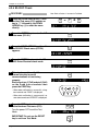
3.4 POS Code
PROCEDURES
Note: Refer to page 14, Section 3.1 to enter the Setup Mode.
➜
➝
➝
➝
2
or
➝
1 Press the DOWN ARROW key ( ) until
the POS Code menu (b02) appears or
key in “2” followed by the DOWN
ARROW key ( ) to enter the menu
directly.
2 Press the ENTER key to enter the
Flag menu (b02-01).
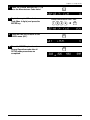
3 Key in the Flag Number (2 digits) and
press the ENTER key.
ENTER
Example: POS code flag “5”
5
Note: In case a 3 digit or 4 digit code is keyed in
by mistake, the last 2 digits are
programmed as the flag code.
➜
ENTER
• Default value is 2
➝
➝
4 Press the DOWN ARROW key ( ) to
enter the Type menu.
5 Key in the POS Code Type (1 to 15)
and press the ENTER key.
Example: POS Code Type “3”
3
➜
ENTER
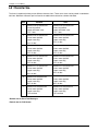
■ POS Code Type
11
12
13
14
15
16
17
18
19
10
11
12
13
14
15
page 20
:
:
:
:
:
:
:
:
:
:
:
:
:
:
:
FFCCCCC(C/P)PPPP(C/D) (default)
FFCCCCCCPPPP(C/D)
FCCCCCC(C/P)PPPP(C/D)
FFCCCCCPPPPP(C/D)
FCCCCCCPPPPP(C/D)
FFCCCC(C/P)PPPPP(C/D)
FFCCCCCCWWWW(C/D)
FCCCCCCWWWWW(C/D)
FCCCCCIIIIII(C/D)
FFCCCCCCPPPP(C/D) – EAN Code
FFCCCCCCWWWW(C/D) – EAN Code
FFCCCC(C/P)WWWWW(C/D)
FFMMMCCPPPPP(C/D)
FFMMCCCPPPPP(C/D)
FFCCCCC(0)PPPP(C/D)
Note: F
= Flag
C
= Item code
P
= Price
W
= Weight
I
= PLU no.
M
= Manufacturer code
(C/P) = Check price
(C/D) = Check digit
(0)
= Fixed zero
ASTRA • Service Manual • Manual No. 0145A
Chapter 3. Setup Mode
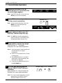
➝
7 Key in the required Manufacturer
Code (Max. 4 digits) and press the
ENTER key.
➝
6 Press the DOWN ARROW key ( ) to
enter the Manufacturer Code menu.
Example: Manufacturer code “1234”
2
1
8 Press the END key to return to the
LABEL menu (b01).
3
4
➜
ENTER
END
9 Press the MODE key to return to
Normal Operation mode after all
SETUP mode procedures are
completed.
MODE
ZERO
ASTRA • Service Manual • Manual No. 0145A
page 21
Chapter 3. Setup Mode
3.5 Bar Code
PROCEDURES
Note: Refer to page 14, Section 3.1 to enter the Setup Mode.
3
➜
➝
➝
➝
or
➝
1 Press the DOWN ARROW key ( ) until
the Bar Code menu (b03) appears or
key in “3” followed by the DOWN
ARROW key ( ) to enter the menu
directly.
2 Press the ENTER key to enter the
Position setup (b03-01).
3 Key in the start position and number
of digits of the PLU Code, and press
the ENTER key.
ENTER
Example: PLU number “44”
4
4
➜
ENTER
Note: Default value “36” indicates 6 digits from
3rd digit of the barcode (step P01-09).
Example : 12345678
DO NOT change the default value unless
directed to do so by Ishida factory
representatives. Changing this value will
affect barcode scanning.
Note: Later versions of Astra use the COPY key
in place of ENTER for added security.
4 Press the END key to return to the
LABEL menu (b01).
END
5 Press the MODE key to return to
Normal Operation mode after all
SETUP mode procedures are
completed.
MODE
ZERO
page 22
ASTRA • Service Manual • Manual No. 0145A
Chapter 3. Setup Mode
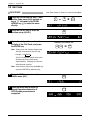
3.6 Default Setup
PROCEDURES
Note: Refer to page 14, Section 3.1 to enter the Setup Mode.
4
➜
➝
➝
➝
or
➝
1 Press the DOWN ARROW key ( ) until
the Default menu (b04) appears or
key in “4” followed by the DOWN
ARROW key ( ) to enter the menu
directly.
2 Press the ENTER key to enter the
Date Flag menu (b04-01).
ENTER
Note: This step sets the default value of the
date print flag.
3 Key in the Date Flag Number (1 to 4)
and press the ENTER key.
1
2
3
4
:
:
:
:
Example: Date Flag number “3”
3
Do not print pack date or expire date
Print pack date only
Print expire date only
Print both pack date and expire date (default)
➜
ENTER
Note: This setting may be overridden during
PLU programming.
➝
5 Key in the number of days for expire
date (Max. 3 digits) as the default data
and press the ENTER key.
➝
4 Press the DOWN ARROW key ( ) to
enter the Shelf Life menu.
Example: Number of days “5”
5
➜
ENTER
Note: 1. This step is required only when “3” or
“4” is selected in Step 3 above.
2. This setting may be overridden during
PLU programming.
6 Press the END key to return to the
LABEL menu (b01).
END
7 Press the MODE key to return to
Normal Operation mode after all
SETUP mode procedures are
completed.
MODE
ZERO
ASTRA • Service Manual • Manual No. 0145A
page 23
Chapter 3. Setup Mode
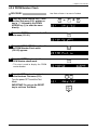
3.7 Total
Select whether production totals are accumulated.
Note: Refer to page 14, Section 3.1 to enter the Setup Mode.
PROCEDURES
5
➜
➝
➝
➝
or
➝
1 Press the DOWN ARROW key ( ) until
the Total menu (b05) appears or key
in “5” followed by the DOWN ARROW
key ( ) to enter the menu directly.
2 Press the ENTER key to enter the
Total Selection menu (b05-01).
ENTER
Note: This menu selects whether or not the
transaction data is added to total data.
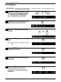
3 Key in “0” or “1” and press the
ENTER key.
Example: Select “1”
1
0 : Not added (default)
1 : Added
4 Press the END key to return to the
LABEL menu (b01).
➜
ENTER
END
5 Press the MODE key to return to
Normal Operation mode after all
SETUP mode procedures are
completed.
MODE
ZERO
page 24
ASTRA • Service Manual • Manual No. 0145A
Chapter 3. Setup Mode
3.8 Forced Tare
If Forced Tare is active,labels can be issued only if a
tare weight is entered.
PROCEDURES
Note: Refer to page 14, Section 3.1 to enter the Setup Mode.
6
➜
➝
➝
➝
or
➝
1 Press the DOWN ARROW key ( ) until
the Forced Tare menu (b06) appears
or key in “6” followed by the DOWN
ARROW key ( ) to enter the menu
directly.
2 Press the ENTER key to enter the
Forced Tare Selection menu (b06-01).
ENTER
Note : This menu selects whether or not the
forced tare function is active.
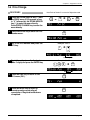
3 Key in “0” or “1” and press the ENTER
key.
Example: Select forced tare activation
1
0 : Forced Tare is not active (default)
1 : Forced Tare is active
➜
ENTER
Note: If Forced Tare is active a tare weight must
be entered before a label can be printed.
If no tare weight is entered, the message
"ENTER TARE" is displayed and an error
buzzer sounds when the PRINT key is
pressed.
4 Press the END key to return to the
LABEL menu (b01).
END
5 Press the MODE key to return to
Normal Operation mode after all
SETUP mode procedures are
completed.
MODE
ZERO
ASTRA • Service Manual • Manual No. 0145A
page 25
Chapter 3. Setup Mode
3.9 Open Price Setup
Select if the operator can make temporary price
changes.
PROCEDURES
Note: Refer to page 14, Section 3.1 to enter the Setup Mode.
7
➜
➝
➝
➝
or
➝
1 Press the DOWN ARROW key ( ) until
the Open Price menu (b07) appears or
key in “7” followed by the DOWN
ARROW key ( ) to enter the menu
directly.
2 Press the ENTER key to enter the
Open Price Selection menu (b07-01).
ENTER
Note: This step is used to select if the operator
can make temporary price changes.
3 Key in “0” or “1” and press the
ENTER key.
Example: Select “1”
1
0 : Open price (default)
1 : Prohibition of temporary price changes
4 Press the END key to return to the
LABEL menu (b01).
➜
ENTER
END
5 Press the MODE key to return to
Normal Operation mode after all
SETUP mode procedures are
completed.
MODE
ZERO
page 26
ASTRA • Service Manual • Manual No. 0145A
Chapter 4. Test Mode
CHAPTER
4
TEST MODE
4.1 Test Mode Entry ..................................... 28
4.2 Hardware Test ........................................ 29
4.2.1
4.2.2
4.2.3
4.2.4
4.2.5
A/D Calibration (C01-01) .................. 29
Key Check (C01-02) .......................... 30
Display Check (C01-03) .................... 31
RS-232C Check (C01-04) .................. 32
PROM Number Check (C01-05) ...... 33
4.3 RAM Clear (C02) ........................................ 34
4.4 Print Head (C03) ..................................... 36
4.5 Sensor Check (C04) .................................. 38
4.6 Total Memory (C05) ................................... 39
4.7 ROM Switch (C06) ...................................... 40
ASTRA • Service Manual • Manual No. 0145A
page 27
Chapter 4. Test Mode
4.1 Test Mode Entry
Test Mode operations (C00) are required when initially setting up the basic functions of the Astra and when checking
hardware operations. When performing these operations, use the Program Key Sheet (located underneath the
Operation Key Sheet) to set up and check the following items.
• C01 :
• C02 :
• C03 :
• C04 :
• C05 :
• C06 :
Hardware Test
RAM Clear
Q
Print Head
A
Sensor Check
Total Memory
ROM Switch
!
W
“
S
SYMBOL
FUNCTION
Z
#
D
@
=
LOWER
CASE
E
,
R
X
PLU
LIST
Y
&
V
U
‘
J
H
}
{
]
C
.
%
G
F
[
B
I
N
EDIT
PLU
SIZE
Ñ
END
←
Ç
↑
↓
(
K
+
M
O
)
L
;
*
INSERT COPY SPACE
PLU PRICE
FILE CHANGE
T
$
:
BACK
SPACE
DELETE NEW
LINE
→
ENTER
P
_
MODE ZERO
7
8
9
4
5
6
1
2
3
0
CLR
TARE
FEED
RESET
PRINT
PLU
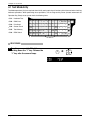
PROCEDURES
1 Turn the power switch ON while
holding down the “1” key. Release the
“1” key after the second beep.
1
➜
1
page 28
ASTRA • Service Manual • Manual No. 0145A
Chapter 4. Test Mode
4.2 Hardware Test
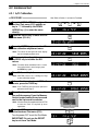
4.2.1 A/D Calibration
PROCEDURES
Note: Refer to Section 4.1 to enter the Test Mode.
➝
➝
➝
➜
1
or
➝
1 Press the DOWN ARROW key ( ) until
the Hard Test menu (C01) appears or
key in “1” followed by the DOWN
ARROW key ( ) to enter the menu
directly.
2 Press the ENTER key to enter the A/D
Data menu (C01-01).
ENTER
3 Press the ENTER key to enter the A/D
Data calibration adjustment menu.
ENTER
Note: The values on the right half of the display
are for example purposes only.
4 With no weight on the platter, press
the ZERO key to initialize the A/D
values.
ZERO
Note: The initial value should be 2000 ±1 count.
If the initial value is out of range, press
the ZERO key again.
5 Place 30 lbs on the platter.
Note: If ASTRA is set as 15 × 0.005kg use 15kg
as the calibration weight.6
6 If the calibration value is not 30000 ±2
counts, press the TARE key.
TARE
Note: If the TARE key was pressed, repeat the
procedure from Step 4.
7 The calibration data must be saved to
non-volitale memory. Press the Memory
Switch located behind the nylon screw
next to the 9-pin serial connector.
Note: Use the sealing kit supplied with the ASTRA
to seal the scale as required by local
regulations.
8 Press the END key two times to return
to the Hardware Test menu (C01).
Turn the power OFF to exit the Test Mode.
Memory Switch
END
END
IMPORTANT: Do not use the RESET
key to exit from Test Mode.
ASTRA • Service Manual • Manual No. 0145A
page 29
Chapter 4. Test Mode
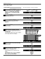
4.2.2 Key Check
PROCEDURES
Note: Refer to Section 4.1 to enter the Test Mode.
➝
➜
1
or
➝
➝
1 Press the DOWN ARROW key ( ) until
the Hard Test menu (C01) appears or
key in “1” followed by the DOWN
ARROW key ( ) to enter the menu
directly.
➝
2 Press the ENTER key to enter the A/D
Data menu (C01-01).
ENTER
➝
➝
3 Press the DOWN ARROW key ( ) until
the Key Check menu (C01-02)
appears.
4 Press the ENTER key to enter the Key
Check menu.
ENTER
5 Press any key to display its data
value. A short beep should be heard
for each key.
6 The numeric value of each key is shown
on the right side of the display.
6
6 Press the RESET key to exit the Key
Check mode.
7 Press the END key to return to the
Hardware Test menu (C01).
Q
!
A
W
“
S
@
=
LOWER
CASE
SYMBOL
FUNCTION
Z
,
2
#
R
$
[
X
PLU
LIST
%
Y
&
U
‘
J
H
}
{
]
C
.
T
G
F
I
+
V
B
N
SIZE
Ñ
↑
EDIT
PLU
END
←
Ç
↓
(
K
O
)
L
;
M
*
INSERT COPY SPACE
PLU PRICE
FILE CHANGE
1
E
D
:
BACK
SPACE
DELETE NEW
LINE
→
ENTER
P
_
MODE ZERO
7
8
9
4
5
6
1
2
3
0
CLR
TARE
•••••••••••••••••
FEED
RESET
PRINT
PLU
12 13 RESET
15 10 • • • • • • • • • • • • • • • • •
26 27
28 29 • • • • • • • • • • • • • • • • •
39 27
40 41 • • • • • • • • • • • • • • • • •
51 52
53 54 • • • • • • • • • • • • • • • • •
64 52
RESET
END
Turn the power OFF to exit the Test
Mode.
IMPORTANT: Do not use the RESET
key to exit from Test Mode.
page 30
ASTRA • Service Manual • Manual No. 0145A
Chapter 4. Test Mode
4.2.3 Display Check
PROCEDURES
Note: Refer to Section 4.1 to enter the Test Mode.
➝
➝
➝
➜
1
or
➝
1 Press the DOWN ARROW key ( ) until
the Hard Test menu (C01) appears or
key in “1” followed by the DOWN
ARROW key ( ) to enter the menu
directly.
2 Press the ENTER key to enter the A/D
Data menu (C01-01).
ENTER
➝
➝
3 Press the DOWN ARROW key ( ) until
the Display Check menu (C01-03)
appears.
4 Press the ENTER key to begin the
display check.
Confirm that the operator and customer
displays are functioning properly.
5 Press the END key two times to return
to the Hardware Test menu (C01).
ENTER
ZERO
NET
END
SAVE
AUTO
PLU
END
Turn the power OFF to exit the Test
Mode.
IMPORTANT: Do not use the RESET
key to exit from Test Mode.
ASTRA • Service Manual • Manual No. 0145A
page 31
Chapter 4. Test Mode
4.2.4 RS-232C Check
PROCEDURES
Note: Refer to Section 4.1 to enter the Test Mode.
➝
➝
➝
➜
1
or
➝
1 Press the DOWN ARROW key ( ) until
the Hard Test menu (C01) appears or
key in “1” followed by the DOWN
ARROW key ( ) to enter the menu
directly.
2 Press the ENTER key to enter the A/D
Data menu (C01-01).
4 Press the ENTER key to enter the RS232C Driver/Receiver check mode.
5 This step is used to verify if the
internal circuitry for serial
communications is functioning
properly.
Short-circuit pin 2 (TxD) and pin 3 (RxD)
on the D-sub 9-pin connector then
press the PRINT key.
➝
➝
3 Press the DOWN ARROW key ( ) until
the RS-232C Check menu (C01-04)
appears.
ENTER
ENTER
PRINT
• When data verification is successful, a long
tone sounds and “PASS” is displayed.
• When data verification is unsuccessful, an
error tone sounds and “ERROR” is displayed.
6 Press the END key two times to return
to the Hardware Test menu (C01).
END
END
Turn the power OFF to exit the Test
Mode.
IMPORTANT: Do not use the RESET
key to exit from Test Mode.
page 32
ASTRA • Service Manual • Manual No. 0145A
Chapter 4. Test Mode
4.2.5 PROM Number Check
PROCEDURES
Note: Refer to Section 4.1 to enter the Test Mode.
➝
➝
➝
➜
1
or
➝
1 Press the DOWN ARROW key ( ) until
the Hard Test menu (C01) appears or
key in “1” followed by the DOWN
ARROW key ( ) to enter the menu
directly.
2 Press the ENTER key to enter the A/D
Data menu (C01-01).
4 Press the ENTER key to enter the
PROM Number check mode.
➝
➝
3 Press the DOWN ARROW key ( ) until
the PROM Number Check menu
(C01-05) appears.
ENTER
ENTER
• This step is used to display the PROM
version number.
5 Press the END key two times to return
to the Hardware Test menu (C01).
Turn the power OFF to exit the Test
Mode.
END
END
IMPORTANT: Do not use the RESET
key to exit from Test Mode.
ASTRA • Service Manual • Manual No. 0145A
page 33
Chapter 4. Test Mode
4.3 RAM Clear
This step is used to itialize the Astra’s memory before
installation or reset the memory after a problem.
PROCEDURES
Note: Refer to Section 4.1 to enter the Test Mode.
➝
➝
➝
➜
2
or
➝
1 Press the DOWN ARROW key ( ) until
the RAM Clear menu (C02) appears or
key in “2” followed by the DOWN
ARROW key ( ) to enter the menu
directly.
2 Press the ENTER key to enter the RAM
Clear menu (C02-01).
3 Press the ZERO key twice to clear all
RAM data.
ENTER
ZERO
ZERO
• This procedure clears all data entered in the
Programming Mode (9000) as well as any
custom label formats.
Note: If SRAM clear is unsuccessful, an error tone
sounds and “ERROR” is displayed.
5 Press the ZERO key twice to reset all
E2ROM data to the default settings.
➝
➝
4 Press the DOWN ARROW key ( ) to
enter the E2ROM Clear step.6
ZERO
ZERO
• This procedure clears all configuration
changes programmed in the Test Mode and
Setup Mode (6000).
IMPORTANT: This procedure must be
performed when the EPROM firmware
chip is upgraded.
Note: If E2ROM Clear is unsuccessful, an error
tone sounds and “ERROR” is displayed.
page 34
➝
➝
6 Press the DOWN ARROW key ( ) to
enter the Test Data step.
ASTRA • Service Manual • Manual No. 0145A
Chapter 4. Test Mode
7 Press the ZERO key twice to create a
set of test data.
ZERO
ZERO
• This procedure creates the following test data:
❚ PLUs 1 to 13*
❚ Extra Messages 1 to 20*
❚ Store Name and Address
IMPORTANT: This procedure clears all
programmed data (Registration Mode)
and resets some configuration
settings (Setup Mode and Test Mode).
Note: If Test Data Set is unsuccessful, an error
tone sounds and “ERROR” is displayed.
*Later versions of Astra create test sets 1
to 10.
8 Press the END key to return to the
Hardware Test menu (C01).
Turn the power OFF to exit the Test
Mode.
END
IMPORTANT: Do not use the RESET
key to exit from Test Mode.
ASTRA • Service Manual • Manual No. 0145A
page 35
Chapter 4. Test Mode
4.4 Print Head
PROCEDURES
Note: Refer to Section 4.1 to enter the Test Mode.
➜
➝
➝
➝
3
or
➝
1 Press the DOWN ARROW key ( ) until
the Print Head menu (C03) appears or
key in “3” followed by the DOWN
ARROW key ( ) to enter the menu
directly.
2 Press the ENTER key to enter the Print
Head menu (C03-01).
3 Enter the resistance value according
to the decal on the print head.
Press the PRINT key to issue a label
with a test pattern.
• The resistance value of the print head can
be set automatically by pressing the COPY
key.
ENTER
Example: Set the resistance to 623 ohms.
6
2
➜
3
or
ENTER
COPY
IMPORTANT: The resistance value
must be re-entered when the print
head is replaced.
➝
➝
4 Press the DOWN ARROW key ( ) to
enter the Print Usage step.6
5 The Print Usage step records the
amount of label stock that has been
printed by the ASTRA.
• Usage is displayed in increments of 100m
(0.1km).
• Reset the usage amount when the print head is
replaced.
❚ A password protects resetting the usage
amount. Enter the password “4141” followed by
the SIZE key. Enter “0” followed by the ENTER
key to reset the usage amount.
page 36
➝
➝
6 Press the DOWN ARROW key ( ) to
enter the Print Value step.
ASTRA • Service Manual • Manual No. 0145A
Chapter 4. Test Mode
7 The Print Value step is used to set the
darkness of the thermal printing.
3
➜
ENTER
• Entry values range from 1 (light) to 9 (dark).
Press the PRINT key to confirm the
print darkness.
8 Press the END key to return to the
Hardware Test menu (C01).
Turn the power OFF to exit the Test
Mode.
END
IMPORTANT: Do not use the RESET
key to exit from Test Mode.
ASTRA • Service Manual • Manual No. 0145A
page 37
Chapter 4. Test Mode
4.5 Sensor Check
Use the steps below to check and/or calibrate the label
sensor.
PROCEDURES
Note: Refer to Section 4.1 to enter the Test Mode.
➜
➝
➝
➝
4
or
➝
1 Press the DOWN ARROW key ( ) until
the Sensor Check menu (C04)
appears or key in “4” followed by the
DOWN ARROW key ( ) to enter the
menu directly.
2 Press the ENTER key to enter the
Sensor Check menu (C04-00).
ENTER
• This step is used to calibrate the label sensor.
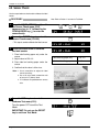
3 Follow the steps below to calibrate
the label sensor.
1. Place label backing paper only under the
sensor.
2. Adjust value to 150 ±10.
3. Place label on backing paper under the
sensor.
Label backing paper only
150 ±10
Label and backing paper
≤ 60
4. Confirm that the value is 60 or less.
Note: 1. Use a screwdriver to adjust the label
sensor sensitivity.
2. Use a #0 cross-head screwdriver with
at least a 2.5" (64mm) shaft.
3. “A” indicates the potentiometer access
hole.
A
4 Press the END key to return to the
Hardware Test menu (C01).
END
Turn the power OFF to exit the Test
Mode.
IMPORTANT: Do not use the RESET
key to exit from Test Mode.
page 38
ASTRA • Service Manual • Manual No. 0145A
Chapter 4. Test Mode
4.6 Total Memory
Use this step to view the amount of free memory
available in the Astra.
PROCEDURES
Note: Refer to Section 4.1 to enter the Test Mode.
5
➜
➝
➝
➝
or
➝
1 Press the DOWN ARROW key ( ) until
the Total Memory menu (C05) appears
or key in “5” followed by the DOWN
ARROW key ( ) to enter the menu
directly.
2 Press the ENTER key to enter the Total
Memory menu (C05-00).
ENTER
• The Total Memory and Remaining Memory
amounts are displayed in KB.
If remaining memory is at or near zero, clear
production total data and/or delete unused
PLUs to regain memory.
3 Press the END key to return to the
Hardware Test menu (C01).
Total Memory
Remaining Memory
END
Turn the power OFF to exit the Test
Mode.
IMPORTANT: Do not use the RESET
key to exit from Test Mode.
ASTRA • Service Manual • Manual No. 0145A
page 39
Chapter 4. Test Mode
4.7 ROM Switch
ROM Switches are used to configure a variety of
miscellaneous settings.
PROCEDURES
Note: Refer to Section 4.1 to enter the Test Mode.
➝
➜
6
or
➝
➝
1 Press the DOWN ARROW key ( ) until
the ROM Switch menu (C06) appears
or key in “6” followed by the DOWN
ARROW key ( ) to enter the menu
directly.
➝
2 Press the ENTER key twice to enter the
ROM Switch menu (C06-00).
ENTER
ENTER
• This step is used to set the ROM Switch data.
ROM Switch
address
3 Procedure:
1. Key in the ROM Switch address and press
the RIGHT ARROW ( ➝ ) key.
Current Data entry
data
position
Example: Disable the RESET key.
6
3
➜
➝
1
➜
ENTER
2. Key in the new data and press the ENTER
key.
• Refer to the ROM Switch table in the next
step.
Note: Use the UP ARROW or RIGHT ARROW
keys to move to a higher numbered
address.
Use the DOWN ARROW or LEFT ARROW
keys to move to a lower numbered address.
page 40
ASTRA • Service Manual • Manual No. 0145A
Chapter 4. Test Mode
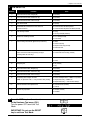
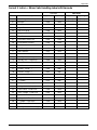
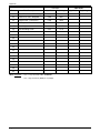
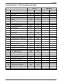
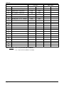
4 ROM Switch List
Address
Function
Data
10
Decimal Point Position, Weight (lb)
03 (Default)
11
Decimal Point Position, Total Price (lb)
03 (Default)
12
Decimal Point Position, Unit Price (lb)
03 (Default)
13
DC motor control
41 (Fixed)
14
Total Mode Accumulation of Piece Count for
00: Count number of labels printed
Fixed Price Items
01: Count number of pieces on labels (Default)
15
Unit Pricing method
00: $/kg
01: $/100g and $/lb (Default)
16
Total Price rounding method
00: 4-5 round (Default)
01: 0/5 round
17
Date Printing selection for @/for Item (Fixed Price)
00: Both
01: Pack Date only
02: Expire Date only (Default)
03: No Date Print
18
Shelf Life Calculation
00: Include pack day
Does Shelf Life include the pack day or begin
01: Count from the next day (Default)
counting from the next day?
19
Field Title Print on Label
00: Do Not Print (Default)
01: Print
10
Weighing unit
00: lb (Default)
01: kg
11
Decimal Point Position, Weight (Kg)
04 (Default)
12
Decimal Point Position, Total Price (Kg)
03 (Default)
13
Decimal Point Position, Unit Price (Kg)
03 (Default)
14
Temporary date change selection
00: Pack and Expire date — MMDDYY (Default)
Note: In operation mode “0” entry disables date printing.
01: Expire date only — MMDDYY
02: Expire date only — enter number of days
15*
Delete total data after upload to PC
00: Do Not Delete (Default)
01: Delete
63
RESET key operation
00: Enable (Default)
01: Disable
*Not available in all models
5 Press the END key two times to return
to the Hardware Test menu (C01).
Turn the power OFF to exit the Test
Mode.
END
END
IMPORTANT: Do not use the RESET
key to exit from Test Mode.
ASTRA • Service Manual • Manual No. 0145A
page 41
Chapter 4. Test Mode
page 42
ASTRA • Service Manual • Manual No. 0145A
Chapter 5. Registration Mode
CHAPTER
5
REGISTRATION MODE
5.1 Registration Mode Entry ....................... 44
5.2 PLU Programming (P01) ........................ 45
5.2.1 Deleting a PLU ................................... 49
5.3 PLU Name (P02)..................................... 50
5.4 Price Change (P03) .............................. 51
5.5 Preset Keys (P04) ................................... 52
5.5.1 Preset Keys — PLU and Tare Values . 52
5.5.2 Preset Function Keys ......................... 54
5.5.3 Deleting All Preset keys ...................... 56
5.6 Shop Name/Address (P05) .................. 57
5.7 Date/Time (P06) .................................... 58
5.8 Extra Message (P07) ............................. 59
5.9 Default PLU (P08) ................................... 60
5.10 PLU List Print (P09) ................................ 61
5.11 Communication (Sending) (P10-01) ..... 62
5.12 Communication (Receiving) (P10-02) .. 63
5.13 Nutrition (P11) ...................................... 64
ASTRA • Service Manual • Manual No. 0145A
page 43
Chapter 5. Registration Mode
5.1 Registration Mode Entry
Registration Mode (P00) is used to program various preset functions required for normal operations to be performed.
When performing these operations, use the Program Key Sheet (located underneath the Operation Key Sheet) to
set up the following items.
• P01 :
• P02 :
• P03 :
• P04 :
• P05 :
• P06 :
• P07 :
• P08 :
• P09 :
• P10 :
• P11 :
PLU programming
PLU name
Q
Price change
Preset key
Shop name/Address
Date/Time
Extra message
Default PLU
W
!
A
“
S
LOWER
CASE
Z
#
D
@
=
SYMBOL
FUNCTION
E
R
$
X
PLU
LIST
&
U
J
H
B
SIZE
Ñ
END
←
+
EDIT
PLU
↑
O
M
)
L
;
N
Ç
(
K
}
V
I
‘
*
INSERT COPY SPACE
PLU PRICE
FILE CHANGE
Y
{
]
C
.
%
G
F
[
,
T
:
BACK
SPACE
DELETE NEW
LINE
↓
→
ENTER
P
_
MODE ZERO
7
8
9
4
5
6
1
2
3
0
CLR
TARE
FEED
RESET
PRINT
PLU
PLU list
Communication
Nutrition
PROCEDURES
1 Ensure that the Initial Display
appears.
ZERO
2 Key in the 4-digit password
(default value: 9000) and press the
MODE key. The Registration mode
display will then appear.
page 44
9
0
0
0
➜
MODE
ASTRA • Service Manual • Manual No. 0145A
Chapter 5. Registration Mode
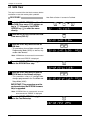
5.2 PLU Programming
PROCEDURES
Note: Refer to Section 5.1 to enter the Registration mode.
1
➜
➝
➝
➝
or
or
PLU
FILE
➝
1 Press the DOWN ARROW key ( ) until
the PLU menu (P01) appears or key in
“1” followed by the DOWN ARROW
key ( ) to enter the menu directly.
Press the PLU FILE key to enter
menu directly.
2 Press the ENTER key to enter the
PLU Number step (P01-01) to register
the data for each PLU.
3 Key in the PLU number (Max. 6 digits)
and press the PLU key.
ENTER
Example: PLU “5”
5
➜
PLU
4 Press the EDIT PLU key to enter the
PLU Name Edit Menu.
EDIT
PLU
(Refer to Chapter 6 “Text Editing” for further
details.)
6 Key in “0”, “1” or “2” and press the
ENTER key to set the Scale mode.
0 : Weighing price
1 : Fixed price
2 : Weighing/Fixed price
2 :
Note: In case “0” or “2” is selected, steps 8.
“P01-04 WEIGHT” and 9. “P01-05 PCS”
are skipped.
➝
➝
5 Press the DOWN ARROW key ( ) or
the ENTER key to enter the Scale
menu.
or
ENTER
Example: Scale Mode “1”
1
ENTER
Note: In case “1” is selected, steps 10. “P01-06
TARE” and 16. “P01-12 PROP TARE” are
skipped.
ASTRA • Service Manual • Manual No. 0145A
page 45
Chapter 5. Registration Mode
7 Key in the unit price or the fixed price
(Max. 5 digits) and press the ENTER
key.
Example: Price “$2.15”
2
5
1
ENTER
8 Key in the fixed weight (Max. 3 digits)
and press the ENTER key.
Note: Fixed weight is available for fixed price
items only.
Note: Enter fixed weight amount in ounces.
Example: Fixed Weight “12 oz”
2
1
ENTER
9 Key in the number of items (Max. 2
digits) and press the ENTER key.
Note: Number of items is available for fixed
price items only.
Example: “2 pcs”
2
ENTER
10 Key in the Tare Weight (Max. 4 digits)
and press the ENTER key.
Note: Applies only to weighing items or
weighing/fixed price items.
ENTER
11 Key in the date print flag (0 to 4) and
press the ENTER key to set the
number of days for expiry.
Date print flag
0 : Default data
1 : No print
2 : Pack date only
3 : Expire date only
4 : Both Pack date and Expire date
Example: Expire date only “3”
ENTER
Note: In case “0 : Default data” is selected, the
date print flag set in step b04-01 Date
Flag (setup mode) is used.
page 46
ASTRA • Service Manual • Manual No. 0145A
Chapter 5. Registration Mode
12 Key in the number of days to
expiration (Max. 3 digits) and press
the ENTER key.
Note: “1000” is the code to designate the
default data. If “1000” is set, the number
of days for shelf life programmed as the
default data in the step “B04-02 SHELF
LIFE” of SETUP mode is set
automatically.
Example: Number of days to expiration “15”
5
1
ENTER
13 Key in the barcode (Max. 8 digits) and
press the ENTER key.
Note: When a new PLU is programmed, the
barcode defaults to the PLU number.
Example: Item code “88888”
ENTER
14 Key in the extra message number
(0 to 99) and press the ENTER key.
Extra message number
0 : No designation
1 to 99 : Extra message number
Example: Extra message number “3”
3
• Extra message should be registered in P07
Extra Message Registration, Section 5.8
ENTER
15 Key in the nutrition panel number
(Max. 3 digits) and press the ENTER
key.
Nutrition Panel number
0 : No designation
1 to 999 : Nutrition Panel number
Example: Panel number “2”
2
• Nutrition Panel should be registered in P11
Nutrition Panel Registration, Section 5.13
ENTER
ASTRA • Service Manual • Manual No. 0145A
page 47
Chapter 5. Registration Mode
16 Key in the proportional tare percent
amount (Max. 50.0) and press the
ENTER key.
Example: Percent tare “2.5”
Note: Porportional tare is the weight of an item
that is the packaging as measured by a
percentage amount.
2
Example: The wrapper on a piece of candy is
2.5 percent of the total weight. By
using portional tare, any amount of
candy can be accurately weighed
on the scale by subtracting the
wrapper weight as a percentage of
the total weight.
5
ENTER
17 To program additional PLUs, repeat
steps 3 through 16.
18 Press the END key to return to the
PLU menu (P01).
END
19 Press the MODE key to return to
normal operation mode after all
operations of Registration Mode are
completed.
MODE
ZERO
page 48
ASTRA • Service Manual • Manual No. 0145A
Chapter 5. Registration Mode
5.2.1 Deleting a PLU
PROCEDURES
Note: Refer to Section 5.1 to enter the Registration mode.
➜
1
➝
➝
➝
or
or
PLU
FILE
➝
1 Press the DOWN ARROW key ( ) until
the PLU menu (P01) appears or key in
“1” followed by the DOWN ARROW
key ( ) to enter the menu directly.
Press the PLU FILE key to enter
menu directly.
2 Press the ENTER key to enter the
PLU Number step (P01-01) to delete
PLUs.
ENTER
3 Key in the PLU number (Max. 6 digits)
and press the PLU key.
Example: PLU “5”
5
➜
PLU
4 Press the DELETE key twice to delete
the PLU.
DELETE
DELETE
Note: The OK buzzer sounds when the PLU is
deleted.
5 Press the END key to return to the
PLU menu (P01).
END
6 Press the MODE key to return to
normal operation mode after all
operations of Registration Mode are
completed.
MODE
ZERO
ASTRA • Service Manual • Manual No. 0145A
page 49
Chapter 5. Registration Mode
5.3 PLU Name
PROCEDURES
Note: Refer to Section 5.1 to enter the Registration mode.
or
2
➜
➝
➝
➝
1
1 Press the DOWN ARROW key ( ) until
the PLU Name (P02) appears or key in
“2” followed by the DOWN ARROW
key ( ) to enter the menu directly.
➝
2 Press the ENTER key to enter the PLU
Number menu to select the PLU.
ENTER
3 Key in the PLU number and press the
PLU key.
Example: “PLU 5”
5
➜
PLU
4 Press the ENTER key to enter the EDIT
menu.
ENTER
Note: Refer to chapter 6 "Text Editing" for further
details.
5 Press the ENTER key after entering/
editing the PLU Name.
ENTER
6 Press the END key to return to the PLU
menu (P01).
END
7 Press the MODE key to return to
normal operation mode after all
operations of Registration Mode are
completed.
MODE
ZERO
page 50
ASTRA • Service Manual • Manual No. 0145A
Chapter 5. Registration Mode
5.4 Price Change
PROCEDURES
Note: Refer to Section 5.1 to enter the Registration mode.
3
➜
➝
➝
➝
or
or
PRICE
CHANGE
➝
1 Press the DOWN ARROW key ( ) until
the PRICE menu (P03) appears or key
in “3” followed by the DOWN ARROW
key ( ) to enter the menu directly.
Press PRICE CHANGE key to enter the
menu directly.
2 Press the ENTER key to enter the PLU
Number menu.
ENTER
3 Key in the PLU number and press the
PLU key.
Example: “PLU 1”
1
➜
PLU
current price
4 Key in the unit price or the fixed price
(Max. 5 digits) and press the ENTER key.
Example: “$1.89”
1
8
➜
9
ENTER
current price
5 Press the END key to return to the
PLU menu (P01).
END
6 Press the MODE key to return to
normal operation mode after all
operations of Registration Mode are
completed.
MODE
ZERO
ASTRA • Service Manual • Manual No. 0145A
page 51
Chapter 5. Registration Mode
5.5 Preset Key
5.5.1 Preset Keys — PLU and Tare values
PROCEDURE
Note: Refer to Section 5.1 to enter the Registration mode.
➝
or
4
➜
➝
➝
1 Press the DOWN ARROW key ( ) until
the Preset Key menu (P04) appears or
key in “4” followed by the DOWN
ARROW key ( ) to enter the menu
directly.
➝
2 Press the ENTER key to enter the
Preset menu (P04-01).
ENTER
3 Press the ENTER key to set the preset
PLU or tare key data.
ENTER
4 Press the PRINT key to switch
between upper and lower preset keys.
Example: Preset key (lower level) as “PLU 2”
Note: Two values can be stored on each preset
key. The PRINT key is used to switch
between upper and lower level. When
lower level is selected, the lower level
indicator will be lit.
PRINT
Lower level
5 Press the FEED key to switch
between the PLU number (Key flag 1)
and tare weight (Key flag 2)
assignment.
Preset key flag
1 : PLU (Max. 6 digits)
2 : Tare (Max. 4 digits)
FEED
Flag No.
Key position
45 on lower level
Note: The default Flag No. is “1”.
6 Key in data (PLU number or Tare
weight) and press the desired preset
key.
Repeat steps 4, 5 and 6 to assign
more preset keys.
page 52
Preset Key
2
Lower level
Flag No.
➜
Key location
Value
ASTRA • Service Manual • Manual No. 0145A
Chapter 5. Registration Mode
7 Press the MODE key to return to the
PLU menu (P01).
MODE
8 Press the MODE key to return to
normal operation mode after all
operations of Registration Mode are
completed.
MODE
ZERO
ASTRA • Service Manual • Manual No. 0145A
page 53
Chapter 5. Registration Mode
5.5.2 Preset Function Keys
Use this procedure to assign function keys to the
keyboard.
PROCEDURE
Note: Refer to Section 5.1 to enter the Registration mode.
4
➜
➝
➝
➝
or
➝
1 Press the DOWN ARROW key ( ) until
the Preset Key menu (P04) appears or
key in “4” followed by the DOWN
ARROW key ( ) to enter the menu
directly.
2 Press the ENTER key to enter the
Preset menu (P04-01).
ENTER
3 Press the ENTER key to set the preset
function keys.
ENTER
4 Key in the desired preset key flag
number (3 to 14), and press the FEED
key, then press the "0" (ZERO) key to
recognize the entry as a function key.
Example: Preset key as “–%”
7
➜
FEED
➜ 0
Note: The default Flag No. is “1”.
Preset function key flag
13 : Fixed price
14 : X (Multiply)
15 : Special price discount
16 : – $ price discount
17 : – % price discount
18 : Save
19 : Extra message
10 : VOID
11 : Peel timer
12 : “99”
13 : “00”
14 : % Tare
Flag No.
Key position 34
Note: See Section 7.3 for an explaination of
function keys.
5 Press the desired preset key.
Repeat step 4 as needed to assign
more function keys.
Preset Key
Flag No.
page 54
Key location
ASTRA • Service Manual • Manual No. 0145A
Chapter 5. Registration Mode
6 Press the MODE key to return to the
PLU menu (P01).
MODE
7 Press the MODE key to return to
normal operation mode after all
operations of Registration Mode are
completed.
MODE
ZERO
ASTRA • Service Manual • Manual No. 0145A
page 55
Chapter 5. Registration Mode
5.5.3 Deleting All Preset Keys
PROCEDURE
Note: Refer to Section 5.1 to enter the Registration mode.
4
➜
➝
➝
➝
or
➝
1 Press the DOWN ARROW key ( ) until
the Preset Key menu (P04) appears or
key in “4” followed by the DOWN
ARROW key ( ) to enter the menu
directly.
2 Press the ENTER key to enter the
Preset menu (P04-01).
ENTER
➝
➝
3 Press the DOWN ARROW key ( ) to
enter the step to delete all preset key
data.
4 Press the ENTER key and then press
the ZERO key twice to delete all
preset key data.
ENTER
➜
ZERO
ZERO
Note: The OK buzzer sounds to notify the
operator that the deletion has been
completed.
5 Press the END key to return to the
PLU menu (P01).
END
6 Press the MODE key to return to
normal operation mode after all
operations of Registration Mode are
completed.
MODE
ZERO
page 56
ASTRA • Service Manual • Manual No. 0145A
Chapter 5. Registration Mode
5.6 Shop Name/Address
PROCEDURES
Note: Refer to Section 5.1 to enter the Registration mode.
➝
or
5 ➜
➝
➝
1 Press the DOWN ARROW key ( ) until
the Shop Address menu (P05)
appears or key in “5” followed by the
DOWN ARROW key ( ) to enter the
menu directly.
➝
2 Press the ENTER key to enter the
Shop Name menu (P05-01) to register
the shop name.
ENTER
3 Press the ENTER key to enter the
Shop Name edit menu to edit the text.
Note: Refer to Chapter 6 “Text Editing” for
further details.
Only character size "1" is available.
Maximum of 46 characters. Italic character
font is not available.
ENTER
SAVE
Edit
Cursor position
4 After text entry, press the ENTER key.
ENTER
➝
➝
5 Press the DOWN ARROW key ( ) to
enter the Shop Address menu
(P05-02) to register the shop address.
6 Press the ENTER key to enter the
Address edit menu to edit the text.
ENTER
Note: Refer to Chapter 6 “Text Editing” for
further details.
Only character size 1 is available.
Maximum of 46 characters. Italic
character font is not available.
SAVE
7 After text entry, press the ENTER key.
ENTER
8 Press the END key to return to the
PLU menu (P01).
END
9 Press the MODE key to return to
normal operation mode after all
operations of Registration Mode are
completed.
MODE
ZERO
ASTRA • Service Manual • Manual No. 0145A
page 57
Chapter 5. Registration Mode
5.7 Date / Time
PROCEDURES
Note: Refer to Section 5.1 to enter the Registration mode.
➝
➜
6
or
➝
➝
1 Press the DOWN ARROW key ( ) until
the DATE/TIME menu (P06) appears or
key in “6” followed by the DOWN
ARROW key ( ) to enter the menu
directly.
➝
2 Press the ENTER key to enter the
Date menu (P06-01) to set the date.
3 Key in the date (8 digits: MMDDYYYY)
and press the ENTER key.
ENTER
Example: “April 8, 2000”
0
4
0
2
8
0
0
0
ENTER
4 Press the ENTER key to enter the
Time menu (P06-02) to set the time.
5 Key in the time (6 digits: HHMMSS)
and press the ENTER key.
ENTER
Example: “15:26:00” (3:26 pm)
1
• Time is entered in 24-hour format.
5
2
6
0
0
ENTER
6 Press the END key to return to the
PLU menu (P01).
END
7 Press the MODE key to return to
normal operation mode after all
operations of Registration Mode are
completed.
MODE
ZERO
page 58
ASTRA • Service Manual • Manual No. 0145A
Chapter 5. Registration Mode
5.8 Extra Message
PROCEDURES
Note: Refer to Section 5.1 to enter the Registration mode.
➝
or
7
➜
➝
➝
1 Press the DOWN ARROW key ( ) until
the Extra Message menu (P07)
appears or key in “7” followed by the
DOWN ARROW key ( ) to enter the
menu directly.
➝
2 Press the ENTER key to enter
Message Number menu (P07-00) to
register the extra message.
ENTER
3 Key in required message number
(1 to 99) and press the PLU key.
Example: Message No. “3”
3
➜
PLU
4 Press the ENTER key to enter the
Extra Message edit menu.
ENTER
Note: Refer to Chapter 6 “Text Editing” for
further details.
SAVE
Edit
Cursor position
5 After text entry, press the ENTER key.
ENTER
6 Press the END key to return to the
PLU menu (P01).
END
7 Press the MODE key to return to
normal operation mode after all
operations of Registration Mode are
completed.
MODE
ZERO
ASTRA • Service Manual • Manual No. 0145A
page 59
Chapter 5. Registration Mode
5.9 Default PLU
Use this step to assign a PLU as the Default PLU, see
step 3 below for details of Default PLU operation.
PROCEDURES
Note: Refer to Section 5.1 to enter the Registration mode.
➜
➝
➝
➝
8
or
➝
1 Press the DOWN ARROW key ( ) until
the DEFAULT PLU menu (P08)
appears or key in “8” followed by the
DOWN ARROW key ( ) to enter the
menu directly.
2 Press ENTER key to enter the default
PLU Number menu (P08-00) to set the
default PLU number.
ENTER
3 Key in PLU number and press the
ENTER key.
• After a transaction, the scale will return to the
default PLU instead of clearing to no PLU.
• Use the default PLU to bypass entry of a PLU for
each transaction.
• A different PLU may be recalled at any time to
override the default PLU during normal operation.
• To disable the default PLU, enter “0” in step P0800.
Example: PLU No. “2222”
2
4 Press the END key to return to the
PLU menu (P01).
2
2
2
➜
ENTER
END
5 Press the MODE key to return to
normal operation mode after all
operations of Registration Mode are
completed.
MODE
ZERO
page 60
ASTRA • Service Manual • Manual No. 0145A
Chapter 5. Registration Mode
5.10 PLU List Print
PROCEDURES
Note: Refer to Section 5.1 to enter the Registration mode.
9
➜
➝
➝
➝
or
or
PLU
LIST
➝
1 Press the DOWN ARROW key ( ) until
the PLU LIST menu (P09) appears or
key in “9” followed by the DOWN
ARROW key ( ) to enter the menu
directly or press the PLU LIST key to
enter the menu directly.
2 Press the ENTER key to enter the PLU
List menu (P09-01).
ENTER
3 Press the PRINT key to print the Item
List.
• Printing starts from the first PLU number.
PRINT
• Starting PLU number can be designated by
entering the PLU number and pressing the
PRINT key.
• To stop printing before completion of the PLU
List, press the ZERO key.
• If the PLU list contains many items, do not
thread the paper onto the take up bobbin. Allow
the labels to remain on the backing paper.
4 Press the END key to return to the
PLU menu (P01).
END
5 Press the MODE key to return to
normal operation mode after all
operations of Registration Mode are
completed.
MODE
ZERO
ASTRA • Service Manual • Manual No. 0145A
page 61
Chapter 5. Registration Mode
5.11 Communication (Sending)
Use this procedure to send data to a PC (Astra Link
and Astra Label programs) or to another Astra scale.
Note: Refer to Section 5.1 to enter the Registration mode.
PROCEDURES
or
1
0
➜
➝
➝
➝
1 Press the DOWN ARROW key ( ) until
the COMMUNICATION menu (P10)
appears or key in “10” followed by
the DOWN ARROW key ( ) to enter
the menu directly.
➝
2 Press the ENTER key to enter the
Send Data menu (P10-01).
ENTER
3 Press the ENTER key to access the
selection of sendable data.
ENTER
➝
Example: Send item “03” (PLU file)
➝
4 Select the data to be sent by pressing
the DOWN ARROW key ( ) or key in the
desired number followed by the ENTER
key to gain direct access.
or
3
➜
ENTER
Uploadable data
P10-01-01 : ALL DATA
02 : SHOP NAME
03 : PLU FILE
04 : PRESETS (preset keyboard data)
05 : MESSAGES (Extra message data)
06 : LABEL FMT (Label format data)
07 : CNFG DATA (E2ROM data)
08 : NUTRITION
09 : TOTAL DATA (Production totals)*
Note: After data is sent properly,
“—— DATA SEND OK—— ” is displayed
temporarily.
If data is not sent properly,
“—— DATA SEND ERROR —— ” is
displayed and an error buzzer sounds.
*Not available in all versions.
5 Press the END key to return to the
PLU menu (P01).
END
6 Press the MODE key to return to normal
operation mode after all operations of
Registration Mode are completed.
MODE
ZERO
page 62
ASTRA • Service Manual • Manual No. 0145A
Chapter 5. Registration Mode
5.12 Communication (Receiving)
Use this procedure to receive data from a PC (Astra
Link and Astra Label programs) or from another Astra
scale.
PROCEDURES
Note: Refer to Section 5.1 to enter the Registration mode.
1
0
➜
➝
➝
➝
or
➝
1 Press the DOWN ARROW key ( ) until
the COMMUNICATION menu (P10)
appears or key in “10” followed by the
DOWN ARROW key ( ) to enter the
menu directly.
2 Press the ENTER key to enter the
Send Data menu (P10-01).
ENTER
➝
➝
3 Press the DOWN ARROW key ( ) to
access the receive data menu.
4 Press the ENTER key to begin
receiving data.
ENTER
Note: After data is received properly,
“—— DATA RECEIVE OK—— ” is
displayed temporarily.
If data is not received properly,
“—— DATA RECEIVE ERROR —— ” is
displayed and an error buzzer sounds.
5 Press the END key to return to the
PLU menu (P01).
END
6 Press the MODE key to return to
normal operation mode after all
operations of Registration Mode are
completed.
MODE
ZERO
ASTRA • Service Manual • Manual No. 0145A
page 63
Chapter 5. Registration Mode
5.13 Nutrition
Note: Refer to Section 5.1 to enter the Registration mode.
PROCEDURES
1
1
➜
➝
➝
➝
or
➝
1 Press the DOWN ARROW key ( ) until
the NUTRITION menu (P11) appears
or key in “11” followed by the DOWN
ARROW key ( ) to enter the menu
directly.
2 Press the ENTER key to enter the
Nutrition Panel menu (P11-00), and
enter the Nutrition Panel No.
3 Press the ENTER key and enter the
serving size using alphanumeric
characters (Max. 10 char.).
4 Press the ENTER key and enter the
Servings per Container using
alphanumeric characters (Max. 4
char.).
ENTER
ENTER
ENTER
5 Press the ENTER key and enter the
Total Calories (Max. 4 digits).
ENTER
6 Press the ENTER key and enter the Fat
Calories (Max. 4 digits).
ENTER
7 Press the ENTER key and enter the
Total Fat amount (Max.3 char.).
ENTER
8 Press the ENTER key and select the
unit of measure (0: “mg” or 1: “g”).
ENTER
page 64
ASTRA • Service Manual • Manual No. 0145A
Chapter 5. Registration Mode
9 Press the ENTER key and enter the
Total Fat percentage (Max. 3 digits).
10 Press the ENTER key and enter the
Saturated Fat amount using
alphanumeric characters (Max. 3 char.).
11 Press the ENTER key and select the
unit of measure (0: “mg” or 1: “g”).
12 Press the ENTER key and enter the
Saturated Fat percentage (Max. 3
digits).
ENTER
ENTER
ENTER
ENTER
13 Press the ENTER key and enter the
Cholesterol amount (Max. 3 char.).
ENTER
14 Press the ENTER key and select the
unit of measure (0: “mg” or 1: “g”).
ENTER
15 Press the ENTER key and enter the
Cholesterol percentage (Max. 3
digits).
ENTER
16 Press the ENTER key and enter the
Sodium amount (Max. 4 char.).
ENTER
17 Press the ENTER key and select the
unit of measure (0: “mg” or 1: “g”).
ENTER
18 Press the ENTER key enter the
Sodium percentage (Max. 3 digits).
ASTRA • Service Manual • Manual No. 0145A
ENTER
page 65
Chapter 5. Registration Mode
19 Press the ENTER key and enter the
total Carbohydrate amount (Max. 4
char.).
20 Press the ENTER key and select the
unit of measure (0: “mg” or 1: “g”).
21 Press the ENTER key and enter the
Carbohydrate percentage (Max. 3
digits).
ENTER
ENTER
ENTER
22 Press the ENTER key and enter the
Dietary Fiber amount (Max. 3 char.).
ENTER
23 Press the ENTER key and select the
unit of measure (0: “mg” or 1: “g”).
ENTER
24 Press the ENTER key and enter the
Dietary Fiber percentage (Max. 3
digits).
ENTER
25 Press the ENTER key enter the Protein
amount (Max. 3 char.).
ENTER
26 Press the ENTER key and select the
unit of measure (0: “mg” or 1: “g”).
ENTER
27 Press the ENTER key and enter the
Protein percentage (Max. 3 digits).
ENTER
28 Press the ENTER key and enter the
Sugar amount (Max. 3 char.).
ENTER
page 66
ASTRA • Service Manual • Manual No. 0145A
Chapter 5. Registration Mode
29 Press the ENTER key and select the
unit of measure (0: “mg” or 1: “g”).
ENTER
30 Press the ENTER key and enter the
Sugar percentage (Max. 3 digits).
ENTER
31 Press the ENTER key and enter the
Vitamin A percentage (Max. 3 digits).
ENTER
32 Press the ENTER key and enter the
Vitamin C percentage (Max. 3 digits).
ENTER
33 Press the ENTER key and enter the
Calcium percentage (Max. 3 digits).
ENTER
34 Press the ENTER key and enter the
Iron percentage (Max. 3 digits).
ENTER
35 Press the END key to return to the
PLU menu (P01).
END
36 Press the MODE key to return to
normal operation mode after all
operations of Registration Mode are
completed.
MODE
ZERO
ASTRA • Service Manual • Manual No. 0145A
page 67
Chapter 5. Registration Mode
page 68
ASTRA • Service Manual • Manual No. 0145A
Chapter 6. Text Editing
CHAPTER
6
TEXT EDITING
6.1 Edit Keys ................................................. 70
6.2 Key Definition ......................................... 70
6.3 Edit Display ............................................. 71
6.4 Edit Examples......................................... 71
6.5 7-Segment Characters ......................... 72
6.6 Wordwrap Function .............................. 73
6.7 Selection Italic Character Font ........... 73
6.8 Character Size ....................................... 74
ASTRA • Service Manual • Manual No. 0145A
page 69
Chapter 6. Text Editing
6.1 Edit Keys
These keys are used while in the Text Editing mode.
Q
!
A
W
“
S
SYMBOL
FUNCTION
Z
#
D
@
=
LOWER
CASE
E
,
R
$
PLU
LIST
&
U
J
H
}
V
B
SIZE
Ñ
END
←
‘
I
K
EDIT
PLU
Ç
↑
↓
)
L
+
N
O
(
;
:
BACK
SPACE
M
*
INSERT COPY SPACE
PLU PRICE
FILE CHANGE
Y
{
]
C
.
%
G
F
[
X
T
DELETE NEW
LINE
→
ENTER
P
_
7
8
9
4
5
6
1
2
3
0
CLR
PRINT
PLU
6.2 Key Definition
BACK
SPACE
NEW
LINE
DELETE
ENTER
➝
➝
➝
➝
SIZE
BACK SPACE
Used to delete a character in the text field by
moving the cursor backwards.
NEW LINE
Used as a carriage return to make a new line.
EDIT
PLU
COPY
DELETE
Used to delete a character in the text field where
the cursor is placed on the display.
ENTER
Used to save character data and complete the
EDIT mode.
UP ARROW
Used to move the cursor up one line.
PLU
LIST
INSERT
RIGHT ARROW
Used to move the cursor right one character.
SIZE
Used to select different character sizes.
After pressing the SIZE key, use the UP ARROW
and DOWN ARROW keys to scroll through the
character sizes. To make fonts italic, press the
SIZE key and then the RIGHT ARROW key.
PRICE
CHANGE
LOWER
CASE
SYMBOL
FUNCTION
Note: The character size of existing text cannot
be changed.
END
END
Used to return to the normal operation mode.
page 70
COPY
Used to copy character data.
Key in the source PLU number and press the
COPY key to copy the character data from
another PLU.
Note: Extra messages may also be copied.
DOWN ARROW
Used to move the cursor down one line.
LEFT ARROW
Used to move the cursor left one character.
EDIT PLU
Used to select the menu item for creating, editing
or deleting PLU descriptions.
PLU
FILE
PLU LIST
Used to select the menu item for printing a PLU
file list. The file is printed on labels.
INSERT
Used to change between inserting or overwriting
characters while editing text fields.
• Indicator ON: Insert (Default)
• Indicator OFF: Overwrite
PRICE CHANGE
Used to directly enter the price change menu
while in the Registration Mode.
LOWER CASE
Used to select between upper and lower case
characters. Available in character size 1 only.
SYMBOL FUNCTION
Used to input right lower symbol of character
keys.
First press the SYMBOL FUNCTION key and
then press the required character keys. Reset is
performed each time one symbol is registered.
PLU FILE
Used to directly enter the PLU programming
menu while in the Registration Mode.
ASTRA • Service Manual • Manual No. 0145A
Chapter 6. Text Editing
6.3 Edit Display
Line number of cursor position
Cursor position counted from first character of the line
"I" is displayed when Italic character is selected
Character size (7 character sizes)
Character line monitor
NET
ZERO
SAVE
Indicator for
Insert/Overwrite
(ON/OFF)
Indicator for Lower Case Characters (ON/OFF)
(Character size 1 only)
Indicator for Character Size Change mode (ON/OFF)
Indicator for Symbol Function Entry mode (ON/OFF)
6.4 Edit Examples
PROCEDURES
1 Ensure that the machine is in Edit
Mode.
SAVE
2 Key in the desired text using the
typewriter style key sheet.
Example: Text as “Thank You”
T
H A N K
SPACE
Y O U
SAVE
3 Press the ENTER key to save the text.
ASTRA • Service Manual • Manual No. 0145A
ENTER
page 71
Chapter 6. Text Editing
6.5 7-Segment Characters
0
1
2
3
4
5
6
7
8
9
A
B
C
D
E
F
G
H
I
J
K
L
M
N
O
P
Q
R
S
T
U
V
W
X
Y
Z
!
“
#
$
%
&
‘
(
)
*
+
,
–
.
/
:
;
<
=
>
?
[
\
]
^
—
@
{
}
page 72
ASTRA • Service Manual • Manual No. 0145A
Chapter 6. Text Editing
6.6 Wordwrap Function
When editing commodity names and extra messages, automatic carriage return is performed when the cursor is at
the furthermost right-hand side position of the character line to be registered.
When the cursor reaches the maximum number of characters for one line, carriage return is made at the nearest
space. When there is no space in the line, carriage return is executed when the line reaches the maximum number
of characters.
Default word wrap width is 60mm. If a narrower width is required, it is entered in Setup step b01-01-03. See Section
3.2 Label Print.
6.7 Selecting Italic Character Font
PROCEDURES
1 Ensure that the machine is in Edit
Mode.
SAVE
2 Press the SIZE key followed by the
RIGHT ARROW key to select the
Italic character font.
➝
ZERO
SIZE
ZERO
SAVE
Italic indicator
3 Press the SIZE key to return to Text
Entry Mode. Key in the desired text.
SIZE
· Standard and italic fonts cannot be printed
on the same line.
· All remaining text entry for this item will be
in italic font.
ZERO
SAVE
· To disable italic font repeat steps 2 and 3.
4 Press the ENTER key to save the text.
ENTER
ASTRA • Service Manual • Manual No. 0145A
page 73
Chapter 6. Text Editing
6.8 Character Size
The Astra is capable of printing seven different character sizes. These seven sizes can be printed in standard or
italic font. Maximum characters per line listed in the table below is based on a 64mm wide label.
Size
Standard
Italic
1*
Maximum 46 characters/line
Prints left justified
(upper and lower case)
14 x 7 dots
Maximum 46 characters/line
Prints left justified
(upper and lower case)
14 x 7 dots
2
Maximum 35 characters/line
Prints center justified
(upper case only)
20 x 10 dots
Maximum 34 characters/line
Prints center justified
(upper case only)
20 x 10 dots
3**
Maximum 24 characters/line
Prints center justified
(upper case only)
30 x 15 dots
Maximum 24 characters/line
Prints center justified
(upper case only)
30 x 15 dots
4
Maximum 18 characters/line
Prints center justified
(upper case only)
40 x 20 dots
Maximum 18 characters/line
Prints center justified
(upper case only)
40 x 20 dots
5
Maximum 12 characters/line
Prints center justified
(upper case only)
60 x 30 dots
Maximum 12 characters/line
Prints center justified
(upper case only)
60 x 30 dots
6
Maximum 9 characters/line
Prints center justified
(upper case only)
80 x 40 dots
Maximum 9 characters/line
Prints center justified
(upper case only)
80 x 40 dots
7
Maximum 6 characters/line
Prints center justified
(upper case only)
120 x 60 dots
Maximum 6 characters/line
Prints center justified
(upper case only)
120 x 60 dots
* Default size for Extra Text Messages.
**Default size for PLU Names.
page 74
ASTRA • Service Manual • Manual No. 0145A
Chapter 7. Normal Mode
CHAPTER
7
NORMAL MODE
7.1 Normal Mode Operation ..................... 76
7.2 Tare Weight Subtraction ....................... 78
7.3 Preset Function Keys ............................. 80
ASTRA • Service Manual • Manual No. 0145A
page 75
Chapter 7. Normal Mode
7.1 Normal Mode Operations
1 Ensure that the power is ON, the
ZERO indicator is lit and confirm that
the initial display appears.
ZERO
Note: If the ZERO indicator is not lit, press the
ZERO key to turn on the indicator.
2 Key in a PLU number and press the
PLU key, or press a preset key.
Example: PLU “1”
➜
1
Note: In case of lower preset keys, press the
MODE key first and then press the
required preset key.
PLU
ZERO
NET
SAVE
PLU
AUTO
3 If the PLU is to be kept on the display
to print additional labels, press the
SAVE key. Otherwise skip this step.
Note: The SAVE key must be registered as a
preset function key in P04 PRESET KEY
of Registration Mode (Section 5.5.2).
4 If necessary, place an item on the
weigh platter to subtract tare weight.
Refer to Section 7.2, “Tare Weight
Subtraction” for a more detailed operation.
Note 1: If the tare weight is already registered in
the specified PLU, this step is
unnecessary.
Note 2: If the PLU is a fixed price item, this step
is unnecessary.
Note 3: If the AUTO indicator is lit, the label is
automatically issued immediately after
the weight has stabilized.
Note4: To eliminate the AUTO indicator, press
the AUTO/MANU key.
5 Key in the data and then press the
required PRESET FUNCTION key if
necessary.
Refer to Section 7.3, “Preset Function Key
Definition” for a more detailed procedure.
Example: Apply a “10%” discount
1
0
➜
-%
Note: The % key must be registered as a preset
function key in P04 PRESET KEY of
Registration Mode (Section 5.5.2).
page 76
ASTRA • Service Manual • Manual No. 0145A
Chapter 7. Normal Mode
6 Key in the required number of items
and press the “X” key, if necessary.
Note 1: This is for fixed price items only.
Note 2: The “X” key must be registered as a
preset function key in “P04 PRESET
KEY” of Registration Mode (Section
5.5.2).
7 Key in the number of labels to be
issued, if necessary.
Note 1: This function is only possible in AUTO
Mode.
Note 2: This is for fixed price items only.
Note 3: In MANUAL Mode, only one label is
issued.
8 Press the PRINT key to issue the label
if the machine is in Manual Mode.
Note 1: When the machine is set to AUTO
Mode, the label is issued automatically
as soon as weighing has stablized (for
weighed items only).
PRINT
Note 2: If in AUTO Mode, and the number of
labels to be issued has not been keyed
in the previous step, labels are issued
continuously. To stop label issue, press
the PRINT key.
Note 3: See operation of PEEL TIMER key in
Section 7.3, "Preset Function Key
Definition". The PEEL TIMER key must
be registered as a preset function key in
"P04 PRESET KEY" of the Registration
Mode (Section 5.5.2).
ASTRA • Service Manual • Manual No. 0145A
page 77
Chapter 7. Normal Mode
7.2 Tare Weight Subtraction
Tare weight can be programmed in a specific PLU. When not programmed, either place the tare on the weigh
platter and press the TARE key or key in the weight if the tare weight is known and press the TARE key.
Note: Tare weight operations mentioned here, may be prohibited in some countries due to Weights and Measures
Regulations.
PROCEDURES
1 Place the tare on the weigh platter.
(Using PLU number 1 without a
programmed tare weight)
ZERO
NET
SAVE
AUTO
PLU
Example: Tare weight “0.02 pounds”
ZERO
NET
SAVE
AUTO
PLU
AUTO
PLU
TARE
2 (Using PLU number 1 with a
programmed tare weight) In this case,
no entry is required.
3 Although the tare is programmed, you
want to delete the tare weight and
actually weigh the tare.
ZERO
NET
SAVE
ZERO
NET
SAVE
AUTO
PLU
ZERO
NET
SAVE
AUTO
PLU
AUTO
PLU
TARE
Note: With no weight on the platter and no
numeric entry, press the TARE key to
clear any previous tare.
ZERO
NET
SAVE
Place the tare (0.02 lb) on the weigh platter.
ZERO
NET
SAVE
AUTO
PLU
AUTO
PLU
TARE
ZERO
page 78
NET
SAVE
ASTRA • Service Manual • Manual No. 0145A
Chapter 7. Normal Mode
4 Temporay tare weight change by
manual entry.
• This procedure is possible only when entering
a larger tare weight.
ZERO
SAVE
AUTO
PLU
Example: Tare weight “0.02 pounds”
• To change to a smaller tare weight the current
tare must first be cleared. Press the TARE
key with no weight on the platter to clear the tare.
2
ZERO
ASTRA • Service Manual • Manual No. 0145A
NET
NET
➜
SAVE
TARE
AUTO
PLU
page 79
Chapter 7. Normal Mode
7.3 Preset Function Keys
The preset function keys listed below must be registered in "P04 PRESET KEY", refer to Section 5.5.2 for details.
FIXED
PRICE
X
SPECIAL
PRICE
FIXED PRICE
Used to temporarily change the selling price for
a fixed price item.
1. Call up the desired fixed price item.
2. Key in the price.
3. Press the FIXED PRICE key.
4. Press the PRINT key to issue label.
MULTIPLE
Used to price multiple pieces of an item.
1. Call up the desired fixed price item.
2. Key in the quantity.
3. Press the X key.
4. Press the PRINT key to issue label.
SPECIAL PRICE
Used to temporarily reduce the selling price.
1. Key in the special price after the total price
is displayed.
2. Press the SPECIAL PRICE key.
3. Press the PRINT key to issue label.
-$
AMOUNT DISCOUNT
Used to temporarily subtract an amount from the
total price.
1. Key in the amount to be discounted after
the total price is displayed.
2. Press the –$ key.
3. Press the PRINT key to issue label.
-%
PERCENT DISCOUNT
Used to temporarily subtract a percentage from
the total price.
1. Key in the percentage to be discounted
after the total price is displayed.
2. Press the –% key.
3. Press the PRINT key to issue label.
SAVE
SAVE
Used to maintain the called up PLU data.
1. Call up the desired PLU.
2. Press the SAVE key.
(SAVE indicator is lit.)
3. Press the SAVE key again to release.
page 80
EXTRA
TEXT
VOID
EXTRA TEXT
Used to temporarily add extra message text to a
PLU description.
1. Call up the desired PLU.
2. Enter the extra message number to be
called up.
3. Press the EXTRA TEXT key.
4. Place the item on the weigh platter.
(Not required for fixed price items.)
5. Press the PRINT key to issue label.
VOID
Used to delete the previous transaction from the
accumulated totals .
1. Press the VOID key immediately after label
issue.
PEEL
TIMER
PEEL TIMER
Used to set the interval time of label issue in the
auto label issue mode for a fixed item.
1. Press the AUTO/MANU key to select
AUTO mode.
2. Call up the desired fixed price item.
3. Key in the interval time (0 to 9) in seconds.
4. Press the PRINT key to issue label.
99
DOUBLE 9
Used to enter two 9’s with one depression in
normal operation mode.
00
DOUBLE 0
Used to enter two 0’s with one depression in
normal operation mode.
%
TARE
PERCENT TARE
Used to set the tare weight based on the
percentage of gross weight.
(U.S.A. and Canada only.)
1. Call up the desired weighing item.
2. Enter the percentage for the tare weight.
(Units of 0.1%.)
3. Press the % TARE key.
4. Place the item on the weigh platter.
5. Press the PRINT key to issue label.
ASTRA • Service Manual • Manual No. 0145A
Chapter 8. Total Mode
CHAPTER
8
TOTAL MODE
8.1 Total Mode Operations ........................ 82
ASTRA • Service Manual • Manual No. 0145A
page 81
Chapter 8. Total Mode
8.1 Total Mode Operations
These operations are usually performed at the end of the working day to verify the processed data from that day.
Note: By default, totals data are not accumulated. To enable totals data accumulation, see Section 3.7 Total.
PROCEDURES
1 Key in the 4-digit password (default
value: 8000) and press the MODE key.
The Total mode display will then
appear.
3 Press the ENTER key to enter the next
step.
0
0
0
➜
MODE
➝
➝
2 Press the DOWN ARROW key ( ) to
enter the Grand Total menu.
8
ENTER
4 Press the PRINT key to print and
issue the Grand Total label.
PRINT
5 Press the END key to return to display
“F01 GRAND TOTAL”.
7 Press the ENTER key to enter the next
step.
➝
➝
6 Press the DOWN ARROW key ( ) to
enter the Total on Label menu.
END
ENTER
· Printing starts from the first PLU number with
totals data.
· Starting PLU number can be designated by
entering the PLU number and pressing the
PRINT key.
· To stop printing before completion, press the
ZERO key.
Note: If the Total Report on Labels contains many
items, don't thread paper onto takeup bobbin.
Allow labels to remain on backing paper.
page 82
ASTRA • Service Manual • Manual No. 0145A
Chapter 8. Total Mode
8 Press the PRINT key to print and
issue the total label of each PLU.
PRINT
9 Press the END key to return to
display “F01 GRAND TOTAL”.
➜
➜
➝
3
➝
➝
➝
or
➝
10 Press the DOWN ARROW key ( )
until the Total on Paper menu
appears or key in “3” followed by the
DOWN ARROW key ( ) to directly
access the menu.
END
11 Press the ENTER key to enter the next
step.
ENTER
12 Press the PRINT key to print and
issue the total data of each item on
continuous thermal report paper.
PRINT
13 Press the END key to return to
display “F01 GRAND TOTAL”.
➝
➝
or
4
➝
14 Press the DOWN ARROW key ( )
until the Total Clear menu appears or
key in “4” followed by the DOWN
ARROW key ( ) to directly access the
menu.
END
15 Press the ENTER key to enter the
next step.
ASTRA • Service Manual • Manual No. 0145A
ENTER
page 83
Chapter 8. Total Mode
16 Press the ZERO key twice to clear all
total data.
ZERO
ZERO
Note: When total data clear is executed
properly, the OK buzzer sounds and
PASS is displayed.
17 Press the END key to return to
display “F01 GRAND TOTAL”.
END
18 Press the MODE key to return to the
normal operation mode after all
operations of TOTAL MODE are
completed.
MODE
ZERO
page 84
ASTRA • Service Manual • Manual No. 0145A
Chapter 9. Subtraction Mode
CHAPTER
9
SUBTRACTION MODE
9.1 Subtraction Mode Operations ............ 86
ASTRA • Service Manual • Manual No. 0145A
page 85
Chapter 9. Subtraction Mode
9.1 Subtraction Mode Operations
These operations are performed in order to adjust the accumulated totals data.
PROCEDURES
1 Key in 7000 and press the MODE key
to enter the Subtraction Mode.
7
0
0
2 Press the ENTER key to enter the
next step.
3 Key in the PLU number to be
subtracted and press the PLU key.
Note: If there is no data for the keyed in PLU,
the error buzzer sounds.
0
➜
MODE
ENTER
Example: PLU number “1”
1
➜
PLU
➝
➝
4 Press the DOWN ARROW key ( ) to
enter the next step.
5 Key in the number of pieces to be
subtracted and press the FEED key.
Example: Subtract 1 piece from PLU “1”
Note: If keyed in number of pieces to be
subtracted exceeds the actual total
number of items, all data is cleared.
page 86
➜
FEED
➝
➝
6 Press the DOWN ARROW key ( ) to
enter the next step.
1
ASTRA • Service Manual • Manual No. 0145A
Chapter 9. Subtraction Mode
7 Key in weight to be subtracted and
press the FEED key.
Example: Subtract 0.25 lb from PLU “1”
2
Note 1: If keyed in weight to be subtracted
exceeds the actual total weight, all
weight is cleared.
➜
5
FEED
Note 2: If there is no weight to be subtracted,
the error buzzer sounds.
➝
9 Key in the price to be subtracted and
press the FEED key.
Note 1: If keyed in price to be subtracted
exceeds the actual total price, all prices
are cleared.
➝
8 Press the DOWN ARROW key ( ) to
enter the next step.
Example: Subtract $1.00 from PLU “1”
1
0
0
➜
FEED
Note 2: If there are no prices to be subtracted,
the error buzzer sounds.
➝
➝
10 Press the DOWN ARROW key ( ) to
enter the next step.
11 Press the PRINT key to execute the
subtraction in accordance with the
above steps.
PRINT
12 Press the MODE key to return to
normal operation mode after all
operations of Subtraction Mode is
completed.
MODE
ZERO
ASTRA • Service Manual • Manual No. 0145A
page 87
Chapter 9. Subtraction Mode
page 88
ASTRA • Service Manual • Manual No. 0145A
Chapter 10. Troubleshooting
CHAPTER
10
TROUBLESHOOTING
10.1 Before Using the Troubleshooting
Chart ..................................................... 90
10.2 Operator Troubleshooting Chart ....... 90
10.3 Service Personnel
Troubleshooting Chart ........................ 91
ASTRA • Service Manual • Manual No. 0145A
page 89
Chapter 10. Troubleshooting
10.1 Before Using the Troubleshooting Chart
If you encounter any problems, before proceeding to the troubleshooting chart, reinitialize the machine by pressing
the RESET key. If the problems continue, follow the instructions listed in the troubleshooting chart. If problems are
not solved using the instructions in the troubleshooting chart, contact your service representative.
TARE
lb
WEIGHT
ZERO
lb
NET
$/lb
UNIT PRICE
SAVE
AUTO
TOTAL PRICE
$
PLU
Capacity 30 × 0.01 lb
10.2 Operator Troubleshooting Chart
Error No.
Description
Countermeasure
PLU description contains too many
characters.
Label printing is not possible because the number
of entered characters is too great for the label.
Press the CLEAR key to return to the previous
screen. Check the programming contents based on
the specific error number.
Extra message is too long.
Store name/address is too long.
page 90
Out of labels.
Replace with a new roll of labels. Press the CLEAR
key to return to the previous screen.
Label size error.
The label size may be different from the
predetermined size. Press the CLEAR key to return
to the previous screen. Confirm the label size and
replace if necessary.
Entered special price is equal to
or over the preset price.
Press the CLEAR key to return to the previous
screen. Try to enter the special price again.
Damaged memory.
Contact your service representative.
Check the scale.
Remove items from weigh platter.
The scale reading was not stable when power was
turned on, or some item was left on the weigh
platter.
Remove any items left on the weigh platter.
Tare weight has not been entered.
A tare weight must be entered before a label can beprinted. Refer to Section 3.8 "Forced Tare". Press
CLEAR key to return to previous screen.
ASTRA • Service Manual • Manual No. 0145A
Chapter 10. Troubleshooting
10.3 Service Personnel Troubleshooting Chart
Description
Cause
Countermeasure
No power
1. Faulty plug connection
2. Burned out fuse
3. Faulty power unit (LSF100-24)
4. Faulty main board (PK-220)
5. Faulty power switch
1.
2.
3.
4.
5.
Re-insert plug
Replace fuse
Check power unit and replace
Check main board and replace
Check power switch and replace
Enters Test Mode when
power is turned ON
1. Faulty keyboard, key switch
2. Faulty main board (PK-220)
1. Check keyboard, key switch and
replace
2. Check main board and replace
Does not proceed after
display check and goes
blank
1. Faulty load cell
2. External vibration
3. Faulty A/D board (PK-219)
4. Faulty main board (PK-220)
5. Faulty power unit (LSF100-24)
1.
2.
3.
4.
5.
Weight readings are
inaccurate or inconsistent
1. Foreign object is underneath the
weigh platter or load cell
2. A four corner limitation screw is
making contact with the limit stop
3. Faulty load cell
4. Faulty A/D board (PK-219)
5. Faulty main board (PK-220)
1. Remove foreign object
A specific digit segment
fails to display (other
elements display properly)
1. Faulty connector connection
2. Faulty main board (PK-220)
3. Faulty display board
1. Check each connector connection
2. Check main board and replace
3. Check display board and replace
Pressing a specific key
gives no response
1. Faulty connector connection
2. Faulty keysheet
1. Confirm connector connection
2. Check keysheet and replace
Programmed data is
changed
1. Faulty battery
1. Replace battery
(battery not rechargeable)
2. Check scale environment
Adjust and/or replace load cell
Check scale environment
Check A/D and replace
Check main board and replace
Check power unit and replace
2. Adjust four-corner limitation screw
3. Check load cell and replace
4. Check A/D board and replace
5. Check main board and replace
2. External noise or static electricity is
affecting scale
3. Faulty main board (PK-220)
3. Check main board and replace
Entire contents of display
disappears during
operation
1. Change in voltage
2. Faulty power unit (LSF100-24)
3. Faulty display board (PK-221)
4. Faulty main board (PK-220)
1. Check power voltage
2. Check power unit and replace
3. Check display board and replace
4. Check main board and replace
Doesn’t print properly
(only 50% is printed)
1. Faulty thermal head cable
2. Faulty thermal head
1. Check cable and replace
2. Check thermal head alignment and
replace
3. Check main board and replace
4. Check thermal head print voltage
and replace power unit
3. Faulty main board (PK-220)
4. Faulty power unit (LSF100-24)
ASTRA • Service Manual • Manual No. 0145A
page 91
Chapter 10. Troubleshooting
page 92
ASTRA • Service Manual • Manual No. 0145A
Chapter 11. Hardware Structure
CHAPTER
11
HARDWARE STRUCTURE
11.1 Mechanical Structure ......................... 94
11.1.1 Exploded Diagram ........................ 94
11.1.2 Parts List .......................................... 95
11.2 Electrical Diagram............................... 97
11.2.1 Block Diagram ............................... 97
11.2.2 Circuit Boards ................................. 98
ASTRA • Service Manual • Manual No. 0145A
page 93
Chapter 11. Hardware Structure
11.1 Mechanical Structure
11.1.1 Exploded Diagram
page 94
ASTRA • Service Manual • Manual No. 0145A
Chapter 11. Hardware Structure
11.1.2 Parts List
ASTRA USA 30lb Service Parts List (89-2803-00)
No.
1
2
3
4
5
6
7
8
9
10
11
12
13
14
15
16
17
18
19
20
21
22
23
24
25
26
27
28
29
30
31
32
33
34
35
36
37
38
39
40
41
42
Parts Name
PLATTER
SHEET:DISPLAY:PANEL
SEALING:PB:CIRCLE
HOUSING:SEALING:CIRCLE
PUSH:RIVET:
NAME PLATE:SPEC:
CASE:UPPER:
SHEET:KEY BOARD:MEMBRANE
SHEET:KEY BOARD:SPACER
SHEET:KEY BOARD:OPERATION
SHEET:KEY BOARD:COVER CLEAR
STICKER:LEVEL:
FRAME:PRINTER:
ACCESSORY:SUPPORT:POST
LABEL SENSOR ASS’Y
DC/DC CONVERTER
HARNESS:S2:DC/DC
STEPPING:MOTOR:PRINT ROLLER
BRACKET:MOTOR:
GEAR:SPUR:DUAL
GEAR:SPUR:SINGLE
MOTOR:GEARED:MICRO ASS’Y:TAKE UP
BRACKET:PUSH:
FRAME:HEAD:
STEP BOLT:PAN HEAD:
BRACKET:LOCK:
BRACKET:HEAD:
COMPRESSION SPRING
THERMAL HEAD
HARNESS:S2:THERMAL HEAD
SHAFT LOCK
TENSION SPRING
SHAFT
SCREW:BAR:FF
GUIDE:LABEL:
LABEL GUIDE BAR
GUIDE:LABEL:
BUSH:RIGHT:
ROLLER:PRINTER:
BUSH:LEFT:
TABLE:LABEL:
BOBBIN
ASTRA • Service Manual • Manual No. 0145A
Remarks
66343
66344
42734
66345
66346
66347
66348
66349
66350
66351
66352
66353
66354
66355
66356
66357
66358
66359
66360
66361
66362
66363
44145
66364
66365
45203
45237
66366
45222
45206
45221
45188
45201
45223
66367
66368
66369
66370
66371
66372
Parts Number
89-3007-05
89-2843-18
00-4761-06
89-2949-00
89-2689-01
89-2852-02
89-2811-00
89-2813-07
89-2846-19
89-2802-15
89-2701-12
89-2714-01
89-2241-16
89-2796-07
89-2782-14
89-2735-00
89-2703-29
89-2777-15
89-2705-17
89-2997-09
89-2713-17
89-2707-23
36-0942-00
89-2709-11
89-2710-16
00-6375-09
36-2636-16
89-2534-08
49-6373-12
00-6377-06
00-6168-04
36-2507-00
20-6991-11
00-6173-03
89-2861-06
89-2776-21
89-2704-13
89-2706-01
89-2702-25
89-2711-10
Quantity
1
2
2
1
1
1
1
1
1
1
1
4
1
1
1
1
1
1
1
1
1
1
1
1
1
1
1
1
1
2
1
1
1
1
1
1
1
1
1
1
page 95
Chapter 11. Hardware Structure
43
44
45
46
47
48
49
50
51
52
53
54
55
56
57
58
59
60
61
62
63
64
65
66
67
68
69
70
71
72
73
74
75
76
77
78
79
80
81
82
83
84
85
86
87
88
LEVER:BOBBIN:
HOLDER:LABEL:
SET:SCREW:
LEVER:GUIDE:LABEL
HOLDER:LABEL:
HOLDER:GUIDE:LABEL
BRACKET:LOAD CELL:
LOAD CELL:C2G1-25K
PLATE SUPPORT
RUBBER:PLATE SUPPORT:
COVER:SIDE:
COVER:FRONT:
STICKER:LABEL ROLL LOADING:
FOOT:LEVEL:
HINGE
PWB PK-221(DISPLAY)
BRACKET:DISPLAY:FRONT
ACCESSORY:SUPPORT:POST
BRACKET:DISPLAY:REAR
HARNESS:S3:DISPLAY
SCREW:SEAL:HEXA
BATTERY
ACCESSORY:CLAMP:
SCREW:SEAL:
CASE:CONNECTOR:
BAR:HEX:MF
BAR:HEX:M
SCREW:SEAL:
BASE
POWER SUPPLY 110V
HARNESS:C3:POWER
HARNESS:S2:POWER(:C3:POWER)
HARNESS:C4:INLET
SWITCH:POWER:
POWER CORD UL
PWB PK-219(A/D BOARD)
PWB PK-220A MAIN BOARD
LEVEL UNIT
STICKER:CAUTION:
ACCESSORY:SUPPORT:
ACCESSORY:SUPPORT:MAIN
PLATE A
RUBBER:PLATE SUPPORT:
BRACKET:SEAL:
FERRITE CORE
UL STICKER
89
C-TICK STICKER
page 96
66373
66374
66375
66376
66377
66378
66379
44414
44410
44406
66380
66381
66382
44423
66383
66384
66385
66386
66387
66389
45128
66388
66390
44474
66391
66392
66393
66394
66395
45132
66396
47073
66397
66398
15438
66399
66400
44425
66419
66420
66402
66403
-
89-2712-22
89-2774-14
89-2860-02
89-2858-04
89-2778-19
89-2830-01
89-2695-22
89-0643-03
89-1884-17
89-1631-11
89-2690-06
89-2691-00
89-2854-19
23-3052-05
89-2694-10
89-2793-06
89-2697-11
89-2708-09
89-2698-14
89-2784-02
00-6609-00
89-2827-09
89-2678-01
89-2025-09
89-2693-16
89-2699-09
89-2700-00
89-2832-08
89-2688-35
89-2760-03
89-2786-00
47-3677-19
89-2785-06
89-0349-08
89-2504-06
89-2637-08
89-2648-09
89-0914-02
89-2747-04
89-2859-08
89-2677-07
89-2973-28
89-3006-01
89-2798-04
1
1
1
1
1
1
1
1
1
3
1
1
1
4
2
1
2
4
2
1
2
1
1
1
1
2
2
1
1
1
1
1
1
1
1
1
1
1
4
4
1
1
-
-
-
1
ASTRA • Service Manual • Manual No. 0145A
Chapter 11. Hardware Structure
11.2 Electrical Diagram
Power Supply
MEMBRANE
KEY SHEET
DC
Paper
Take Up
Stepping
Print Roller
11.2.1 Block Diagram
ASTRA • Service Manual • Manual No. 0145A
page 97
Chapter 11. Hardware Structure
11.2.2 Circuit Boards
Note: Circuit boards are precision equipment requiring special handling. Check for static electricity before
handling.
Main Board (PK-220)
This circuit board contains the CPU as well as controlling the displays, thermal head, printer drive and take-up
motors, weight processing, and price calculations.
JP Switch Setting (Fixed)
JP1 to JP3
Transmission Setting
Short-circuiting for A-side (RS-232C) only
JP6
HL connection for UDP65626
Short-circuit 1-2 (VCC)
JP4, JP5, JP7, JP8
(not in use)
Connector List
No.
CN1
CN2
CN3
CN4
CN5
CN6
CN7
CN8
CN9
CN10
CN11
CN12
CN13
CN17
TP1
TP2
TP3
TP4
TP5
TP6
Details
Battery: 3V Lithium CR 1/2 AA (non-rechargeable)
RS232C D-sub-9pin
Stepping motor - Print roller drive
Keysheet
Thermal head
DC/DC Converter Pin 1: 24V
Pin 2: -27V (Vf1)
Pin 3: -27V (Vf2)
Pin 4: -37V (-VG)
Pin 5: Ground
Label sensor
Pin 1: 5V
Pin 2: 1.1V
Pin 3: 0V (Ground)
Pin 4: Sensor: backing paper only >3V, label and backing paper <1.5V
DC motor - Backing paper take up
Not in use
A/D circuit board
Power
Pins 1, 2, 3: 24V
Pins 4, 5, 6: Ground
Display board
Pins 35, 37: -27V (Vf1)
Pins 38: -37V (-VG)
Pins 39, 40: -27V (Vf2)
Not in use
Not in use
RST
Not in use
GND
5V* (VCC)
24V* (VH)
Battery* Power on: 5V, power off: 2.8V or less
*Measured to TP3 (Ground)
page 98
ASTRA • Service Manual • Manual No. 0145A
Chapter 11. Hardware Structure
Display Board (PK-221)
Receives signal from Main Board and displays data accordingly.
JP1 Switch Setting
Decimal point selection
Note
Short-circuit COM-DP
,
-
Short-circuit COM-VG
.
USA standard
PK-221 Wiring Diagram
J1
ASTRA • Service Manual • Manual No. 0145A
page 99
Chapter 11. Hardware Structure
A/D Board (PK-219)
This amplifies the load cell output signal (analog) and changes it to digital.
PK-219 Wiring Diagram
page 100
ASTRA • Service Manual • Manual No. 0145A
Chapter 12. Maintenance
CHAPTER
12
MAINTENANCE
12.1 Daily Maintenance ........................... 102
12.2 Setting the Power Supply Unit
(LSF100-24S) .............................................. 103
12.3 Parts Replacement.................................. 104
12.3.1 Replacing the Thermal Head..... 104
12.3.2 Replacing the Load Cell ............ 105
12.3.3 Replacing the Print Roller ........... 108
12.3.4 Replacing the Keysheet ............. 110
ASTRA • Service Manual • Manual No. 0145A
page 101
Chapter 12. Maintenance
12.1 Daily Maintenance
It is recommend that the following measures be performed on the machine on a daily basis.
Keep the machine and keysheet free of dust and
dirt.
Ensure that there is a sufficient amount of labels
remaining in the machine.
Clean the thermal head with a cotton swab and
cleaning alcohol (ethanol) supplied with scale.
Ensure that all spills are wiped clean, especially on
the weigh platter.
page 102
ASTRA • Service Manual • Manual No. 0145A
Chapter 12. Maintenance
12.2 Setting the Power Supply Unit (LSF100-24S)
Power Supply
Specification Plate
IMPORTANT: Turn the scale off and unplug the power cord before beginning the following procedure.
The power supply can be switched from 110V AC input
to 220V AC input by moving the jumper from “100V” to
“200V”.
The same fuse is used for both 110V and 220V
configuration.
Jumper to select 110V or 220V input
Fuse
VR1 and VR21 are factory set. Don’t re-adjust them.
The LED21 is On when 24V is output.
1) VR1: Adjusts over current protection point.
Adjusted to 110% to 130% of peak current
2) VR21: Adjusts DC voltage output to 24V ±1% .
LED21 (24V DC output)
VR1 and VR21
ASTRA • Service Manual • Manual No. 0145A
page 103
Chapter 12. Maintenance
12.3 Parts Replacement
12.3.1 Replacing the Thermal Head
IMPORTANT: Turn the scale off and unplug the power cord before beginning the following procedure.
1. Remove the two screws underneath the scale and
remove the front printer cover.
B
2. Loosen the two screws fastening the thermal head.
A
3. Remove screw A. Raise lever B and pull out the
thermal head.
4. Disconnect the thermal head from the ribbon cable.
5. Note the resistance of the new thermal head.
6. Install the new thermal head following Steps 1
through 4 in reverse order.
page 104
7. Enter Test Mode, Step C03, and set the new thermal
head resistance and reset the print usage value to
zero. (Refer to Section 4.4 Print Head)
ASTRA • Service Manual • Manual No. 0145A
Chapter 12. Maintenance
12.3.2 Replacing the Load Cell
IMPORTANT: Turn the scale off and unplug the power cord before beginning the following procedure.
After replacing the load cell, it may be necessary to have the scale re-certified. (Refer to local regulations.)
1. Remove the weigh platter.
2. Remove the two screws underneath the scale and
remove the front printer cover.
3. Remove the three screws underneath the scale that
secure the cover.
4. Remove the screw fastening the cover.
Tip the cover forward.
5. Lift the collar on the keyboard cable connector.
Disconnect the keyboard cable.
6. Remove the two weigh platter support screws.
(5mm allen wrench).
ASTRA • Service Manual • Manual No. 0145A
page 105
Chapter 12. Maintenance
7. Use a soldering iron to remove the load cell cable
from the A/D board.
8. Remove the three socket head bolts (4mm) and
remove the load cell assembly.
Install the new load cell.
9. Use a soldering iron to solder the load cell cable to
the A/D board.
10. Position and fasten the weigh platter support.
(Note: the solid tray support is in the right, operator
side corner).
11. Check four-corner adjustment. Place a weight equal
to scale capacity (30lbs/15kg) plus 10% (3lbs/1.5kg)
on each corner of the weigh platter. If necessary,
rotate each of the four corner adjustment screws
so that they barely make contact with the limit stops
when the weight is loaded.
12. Lift the collar on the keyboard cable conector. Insert
the keyboard cable in to the main board connector.
Push the collar down to secure the cable.
page 106
ASTRA • Service Manual • Manual No. 0145A
Chapter 12. Maintenance
13. Fasten the cover.
14. Reinstall the three screws underneath the scale that
secure the cover.
15. Place the weigh platter on the support. Check that
the main body cover and weigh platter are properly
aligned. If they are not properly aligned, remove
and re-fasten the weigh platter support and tighten
after adjustment.
16. Enter Test Mode, Step C01-01 and calibrate the
scale. (Refer to Section 4.2.1 A/D Calibration)
ASTRA • Service Manual • Manual No. 0145A
page 107
Chapter 12. Maintenance
12.3.3 Replacing the Print Roller
IMPORTANT: Turn the scale off and unplug the power cord before beginning the following procedure.
The main body cover must be removed. Since the certification seal has to be removed, it may be necessary to
have the scale re-certified. (Refer to local regulations)
1. Remove the weigh platter.
2. Remove the two screws underneath the scale and
remove the front printer cover.
3. Remove the three screws underneath the scale that
secure the cover.
4. Remove the screw fastening the cover.
Tip the cover forward.
A
5. Lift the collar on the keyboard cable connector.
Disconnect the keyboard cable.
page 108
6. Raise lever A.
ASTRA • Service Manual • Manual No. 0145A
Chapter 12. Maintenance
7. Remove the screw and plastic clip holding the print
roller.
8. Remove the spring pin and remove the gear and
print roller.
9. Install the new print roller following Steps 1 through
8 in reverse order. Be sure to secure the keyboard
cable by pressing down on the connector collar after
inserting the cable.
ASTRA • Service Manual • Manual No. 0145A
page 109
Chapter 12. Maintenance
12.3.4 Replacing the Keysheet
IMPORTANT: Turn the scale off and unplug the power cord before beginning the following procedure.
IMPORTANT: Once the keyboard has been removed, it cannot be reused. It is strongly recommended that
the new keyboard be connected and tested while it is still loose. This will confirm that the
original keys are faulty.
1. Remove the weigh platter.
2. Remove the two screws underneath the scale and
remove the front printer cover.
3. Remove the 3 screws underneath the scale that
secure the cover.
4. Remove the screw fastening the cover.
Tip the cover forward.
page 110
ASTRA • Service Manual • Manual No. 0145A
Chapter 12. Maintenance
5. Lift the collar on the keyboard cable connector.
Disconnect the keyboard cable.
6. Insert a screwdriver in the area indicated by the
arrow. Peel off the keyboard but be careful not to
damage the main body.
7. Peel off the backing paper of the new keyboard.
Be careful not to allow any debris to stick to the
keyboard. Thread the cable through the main body
cover and carefully attach the keyboard.
8. Lift the collar on the keyboard cable connector.
Insert the keyboard cable in to the main board
connector. Push the collar down to secure the cable.
ASTRA • Service Manual • Manual No. 0145A
page 111
Chapter 12. Maintenance
9. Fasten the cover.
10. Reinstall the three screws underneath the scale that
secure the cover.
11. Place the weigh platter on the support. Check that
the main body cover and weigh platter are properly
aligned. If they are not properly aligned, remove
and re-fasten the weigh platter support and tighten
after adjustment.
12. Enter Test Mode C01-02 to check that all keys
function properly. (Refer to Section 4.2.2 Key
Check)
page 112
ASTRA • Service Manual • Manual No. 0145A
Appendix
APPENDIX
A.1 Sample Labels .................................... 114
A.2 Label Format Worksheets .................. 119
A.3 Communication Cable Wiring
Diagram .............................................. 135
ASTRA • Service Manual • Manual No. 0145A
page 113
Appendix
A.1 Sample Labels
Shown below and on the following pages are sample Weighed and Fixed Price Item labels.
page 114
ITEM LABEL
TEST LABEL
TOTALS LABEL (GRAND TOTAL)
TOTALS LABEL (ITEM)
ASTRA • Service Manual • Manual No. 0145A
Appendix
WEIGHED ITEM
FIXED PRICE ITEM
Format #1 (60mm × 44mm) Part #47732
WEIGHED ITEM
FIXED PRICE ITEM
Format #2 (64mm × 47mm) Part #47733
ASTRA • Service Manual • Manual No. 0145A
page 115
Appendix
WEIGHED ITEM
FIXED PRICE ITEM
Format #3 (64mm × 85mm – Safe Handling) Part #47743
WEIGHED ITEM
FIXED PRICE ITEM
Format #4 (64mm × 59mm – Safe Handling) Part #47736
page 116
ASTRA • Service Manual • Manual No. 0145A
Appendix
WEIGHED ITEM
FIXED PRICE ITEM
Format #5 (64mm × 37mm – Non-barcode) Part #47762
WEIGHED ITEM
FIXED PRICE ITEM
Format #6 (64mm × 59mm – Extended Text) Part #47735
(Not available in all versions)
ASTRA • Service Manual • Manual No. 0145A
page 117
Appendix
WEIGHED ITEM
FIXED PRICE ITEM
Format #7 (64mm × 85mm – Extended Text) Part #47743
(Not available in all versions)
WEIGHED ITEM
FIXED PRICE ITEM
Format #8 (64mm × 85mm Reduced S.H.) Part #47745
(Not available in all versions)
page 118
ASTRA • Service Manual • Manual No. 0145A
Appendix
A.2 Label Format Worksheets
Format 1: 60mm × 44mm Label with Barcode
Old Value
Field #
Field Description
New Value
X (0) Width
Y (1) Height
X (0) Width
Y (1) Height
(Fixed)
(Fixed)
00
Label Image Size
0600
0440
01
Barcode
0045
0240
02
Pack Date
0154
0287
03
Expire Date
0011
0287
04
Unit Price ($/lb)
0297
0287
05
Weight
0458
0287
06
Total Price
0381
0143
07
Discounted Total Price
0401
0143
08
Price Before Discount
0401
0110
09
PLU Number
0486
0213
10
PLU Description
0015
0430
11
Store Address
0015
0040
12
Store Name
0015
0065
13
“Sell By…” title - Weighed
0010
0317
14
“Sell By” title - Fixed Price
0010
0317
15
“Total Price” title - Fixed Price
0350
0195
16
Total Ounces
0338
0247
17
Pounds - inside ( )
0435
0247
18
Ounces - inside ( )
0513
0247
19
“oz” symbol - Total Ounces
0397
0236
20
“(” symbol
0420
0247
21
“)” symbol
0578
0247
22
“lb” symbol - inside ( )
0477
0236
23
“oz” symbol - inside ( )
0555
0236
24
Piece Count - Fixed Price
0157
0291
25
“PCS” symbol - Fixed Price
0224
0287
26
@ Count - Fixed Price
0305
0291
27
“@” symbol - Fixed Price
0286
0287
28
“/” symbol - Fixed Price
0373
0287
29
@/For Price - Fixed Price
0392
0291
30
“Sell By…” title - F.P. + Weigh
0010
0317
ASTRA • Service Manual • Manual No. 0145A
page 119
Appendix
Old Value
New Value
Field #
Field Description
X (0) Width
Y (1) Height
31
“Total Price” title - F.P. + Weigh
0350
0195
32
“Total Price” title - Weighed
0350
0195
33
Single Piece - Fixed Price
0157
0291
34
“PC” symbol - Fixed Price
0224
0287
35
Tare Weight
0338
0247
X (0) Width
Y (1) Height
36
37
38
39
40
41
42
43
44
45
46
47
48
49
50
Note: Navigation - use ↑ ↓ keys to select FIELD NUMBERS
- use → key to select X (Width) or Y (Height)
page 120
ASTRA • Service Manual • Manual No. 0145A
Appendix
Format 2: 64mm × 47mm Label with Barcode
Old Value
Field #
Field Description
New Value
X (0) Width
Y (1) Height
X (0) Width
Y (1) Height
(Fixed)
(Fixed)
00
Label Image Size
0600
0470
01
Barcode
0030
0260
02
Pack Date
0185
0335
03
Expire Date
0020
0335
04
Unit Price ($/lb)
0345
0335
05
Weight
0475
0335
06
Total Price
0405
0185
07
Discounted Total Price
0440
0190
08
Price Before Discount
0440
0155
09
PLU Number
0325
0192
10
PLU Description
0015
0470
11
Store Address
0015
0035
12
Store Name
0015
0060
13
“Sell By…” title - Weighed
0025
0360
14
“Sell By” title - Fixed Price
0025
0360
15
“Total Price” title - Fixed Price
0416
0251
16
Total Ounces
0336
0287
17
Pounds - inside ( )
0434
0287
18
Ounces - inside ( )
0510
0287
19
“oz” symbol - Total Ounces
0394
0276
20
“(” symbol
0416
0287
21
“)” symbol
0572
0287
22
“lb” symbol - inside ( )
0471
0278
23
“oz” symbol - inside ( )
0549
0278
24
Piece Count - Fixed Price
0155
0335
25
“PCS” symbol - Fixed Price
0225
0330
26
@ Count - Fixed Price
0305
0335
27
“@” symbol - Fixed Price
0285
0330
28
“/” symbol - Fixed Price
0375
0330
29
@/For Price - Fixed Price
0390
0335
30
“Sell By…” title - F.P. + Weigh
0025
0360
ASTRA • Service Manual • Manual No. 0145A
page 121
Appendix
Old Value
New Value
Field #
Field Description
X (0) Width
Y (1) Height
31
“Total Price” title - F.P. + Weigh
0416
0251
32
“Total Price” title - Weighed
0416
0251
33
Single Piece - Fixed Price
0155
0335
34
“PC” symbol - Fixed Price
0225
0330
35
Tare Weight
0336
0287
X (0) Width
Y (1) Height
36
37
38
39
40
41
42
43
44
45
46
47
48
49
50
Note: Navigation - use ↑ ↓ keys to select FIELD NUMBERS
- use → key to select X (Width) or Y (Height)
page 122
ASTRA • Service Manual • Manual No. 0145A
Appendix
Format 3: 64mm × 85mm Safe Handling Label with Barcode
Old Value
Field #
Field Description
New Value
X (0) Width
Y (1) Height
X (0) Width
Y (1) Height
(Fixed)
(Fixed)
00
Label Image Size
0600
0850
01
Barcode
0030
0260
02
Pack Date
0185
0335
03
Expire Date
0020
0335
04
Unit Price ($/lb)
0345
0335
05
Weight
0475
0335
06
Total Price
0405
0185
07
Discounted Total Price
0440
0190
08
Price Before Discount
0440
0155
09
PLU Number
0325
0192
10
PLU Description
0015
0830
11
Store Address
0015
0035
12
Store Name
0015
0060
13
“Sell By…” title - Weighed
0025
0360
14
“Sell By” title - Fixed Price
0025
0360
15
“Total Price” title - Fixed Price
0416
0251
16
Total Ounces
0336
0287
17
Pounds - inside ( )
0434
0287
18
Ounces - inside ( )
0510
0287
19
“oz” symbol - Total Ounces
0394
0276
20
“(” symbol
0416
0287
21
“)” symbol
0572
0287
22
“lb” symbol - inside ( )
0471
0278
23
“oz” symbol - inside ( )
0549
0278
24
Piece Count - Fixed Price
0155
0335
25
“PCS” symbol - Fixed Price
0225
0330
26
@ Count - Fixed Price
0305
0335
27
“@” symbol - Fixed Price
0285
0330
28
“/” symbol - Fixed Price
0375
0330
29
@/For Price - Fixed Price
0390
0335
30
“Sell By…” title - F.P. + Weigh
0025
0360
ASTRA • Service Manual • Manual No. 0145A
page 123
Appendix
Old Value
New Value
Field #
Field Description
X (0) Width
Y (1) Height
31
“Total Price” title - F.P. + Weigh
0416
0251
32
“Total Price” title - Weighed
0416
0251
33
Single Piece - Fixed Price
0155
0335
34
“PC” symbol - Fixed Price
0225
0330
35
Tare Weight
0336
0287
36
Safe Handling Panel
0010
0716
X (0) Width
Y (1) Height
37
38
39
40
41
42
43
44
45
46
47
48
49
50
Note: Navigation - use ↑ ↓ keys to select FIELD NUMBERS
- use → key to select X (Width) or Y (Height)
page 124
ASTRA • Service Manual • Manual No. 0145A
Appendix
Format 4: 64mm × 59mm Safe Handling Label with Barcode
Old Value
Field #
Field Description
New Value
X (0) Width
Y (1) Height
X (0) Width
Y (1) Height
(Fixed)
(Fixed)
00
Label Image Size
0600
0600
01
Barcode
0010
0205
02
Pack Date
0436
0240
03
Expire Date
0436
0280
04
Unit Price ($/lb)
0185
0250
05
Weight
0020
0250
06
Total Price
0405
0150
07
Discounted Total Price
0440
0160
08
Price Before Discount
0440
0125
09
PLU Number
0305
0192
10
PLU Description
0025
0600
11
Store Address
0015
0035
12
Store Name
0015
0060
13
“Sell By…” title - Weighed
0330
0275
14
Total Ounces
0325
0205
15
Pounds - inside ( )
0435
0205
16
Ounces - inside ( )
0510
0205
17
“oz” symbol - Total Ounces
0385
0195
18
“(” symbol
0415
0205
19
“)” symbol
0575
0205
20
“lb” symbol - inside ( )
0475
0195
21
“oz” symbol - inside ( )
0550
0195
22
Piece Count - Fixed Price
0040
0255
23
“PCS” symbol - Fixed Price
0090
0250
24
“Sell By…” title - F.P. + Weigh
0330
0275
25
Single Piece - Fixed Price
0040
0255
26
“PC” symbol - Fixed Price
0090
0250
27
“Sell By” title - Weighed
0330
0275
28
Tare Weight
0350
0200
29
30
ASTRA • Service Manual • Manual No. 0145A
page 125
Appendix
Old Value
Field #
Field Description
X (0) Width
Y (1) Height
New Value
X (0) Width
Y (1) Height
31
32
33
34
35
36
37
38
39
40
41
42
43
44
45
46
47
48
49
50
Note: Navigation - use ↑ ↓ keys to select FIELD NUMBERS
- use → key to select X (Width) or Y (Height)
page 126
ASTRA • Service Manual • Manual No. 0145A
Appendix
Format 5: 64mm × 37mm Non Barcode Label
Old Value
Field #
Field Description
New Value
X (0) Width
Y (1) Height
X (0) Width
Y (1) Height
(Fixed)
(Fixed)
00
Label Image Size
0600
0380
01
Pack Date
0010
0225
02
Expire Date
0010
0160
03
Unit Price ($/lb)
0155
0225
04
Weight
0285
0225
05
Total Price
0415
0210
06
Discounted Total Price
0430
0210
07
Price Before Discount
0430
0175
08
PLU Number
0470
0110
09
PLU Description
0010
0375
10
Store Address
0015
0030
11
Store Name
0015
0055
12
“Packed On…” title - Weighed
0020
0260
13
“Packed On…” title - Fixed Price
0020
0260
14
“Total Price” title - Fixed Price
0415
0260
15
Total Ounces
0160
0160
16
Pounds - inside ( )
0257
0160
17
Ounces - inside ( )
0335
0160
18
“oz” symbol - Total Ounces
0219
0150
19
“(” symbol
0242
0160
20
“)” symbol
0400
0160
21
“lb” symbol - inside ( )
0299
0150
22
“oz” symbol - inside ( )
0377
0150
23
Piece Count - Fixed Price
0145
0195
24
“PCS” symbol - Fixed Price
0185
0193
25
@ Count - Fixed Price
0250
0195
26
“@” symbol - Fixed Price
0235
0193
27
“/” symbol - Fixed Price
0290
0193
28
@/For Price - Fixed Price
0305
0195
29
“Packed On…” title - F.P. + Weigh
0020
0260
30
“Total Price” title - F.P. + Weigh
0415
0260
ASTRA • Service Manual • Manual No. 0145A
page 127
Appendix
Old Value
Field #
Field Description
New Value
X (0) Width
Y (1) Height
31
“Total Price” title - Weighed
0415
0260
32
Single Piece - Fixed Price
0145
0195
33
“PC” symbol - Fixed Price
0185
0193
34
“Sell By” title - Fixed Price
0025
0190
35
“Sell By” title - Weighed
0025
0190
36
“Sell By” title - Fix. Pr. + Weigh
0025
0190
37
Tare Weight
0340
0160
X (0) Width
Y (1) Height
38
39
40
41
42
43
44
45
46
47
48
49
50
Note: Navigation - use ↑ ↓ keys to select FIELD NUMBERS
- use → key to select X (Width) or Y (Height)
page 128
ASTRA • Service Manual • Manual No. 0145A
Appendix
Format 6: 64mm × 59mm Extended Text Label with Barcode
(Not available in all versions)
Old Value
Field #
Field Description
New Value
X (0) Width
Y (1) Height
X (0) Width
Y (1) Height
(Fixed)
(Fixed)
00
Label Image Size
0600
0590
01
Barcode
0030
0275
02
Pack Date
0185
0330
03
Expire Date
0020
0330
04
Unit Price ($/lb)
0345
0335
05
Weight
0475
0335
06
Total Price
0405
0195
07
Discounted Total Price
0440
0195
08
Price Before Discount
0440
0160
09
PLU Number
0325
0241
10
PLU Description
0020
0590
11
Store Address
0015
0035
12
Store Name
0015
0060
13
“Sell By…” title - Weighed
0025
0360
14
“Sell By” title - Fixed Price
0025
0360
15
“Total Price” title - Fixed Price
0416
0251
16
Total Ounces
0336
0287
17
Pounds - inside ( )
0434
0287
18
Ounces - inside ( )
0510
0287
19
“oz” symbol - Total Ounces
0394
0276
20
“(” symbol
0416
0287
21
“)” symbol
0572
0287
22
“lb” symbol - inside ( )
0471
0278
23
“oz” symbol - inside ( )
0549
0278
24
Piece Count - Fixed Price
0155
0335
25
“PCS” symbol - Fixed Price
0225
0330
26
@ Count - Fixed Price
0305
0335
27
“@” symbol - Fixed Price
0285
0330
28
“/” symbol - Fixed Price
0375
0330
29
@/For Price - Fixed Price
0390
0335
30
“Sell By…” title - F.P. + Weigh
0025
0360
ASTRA • Service Manual • Manual No. 0145A
page 129
Appendix
Old Value
New Value
Field #
Field Description
X (0) Width
Y (1) Height
31
“Total Price” title - F.P. + Weigh
0416
0251
32
“Total Price” title - Weighed
0416
0251
33
Single Piece - Fixed Price
0155
0335
34
“PC” symbol - Fixed Price
0225
0330
35
Tare Weight
0336
0287
X (0) Width
Y (1) Height
36
37
38
39
40
41
42
43
44
45
46
47
48
49
50
Note: Navigation - use ↑ ↓ keys to select FIELD NUMBERS
- use → key to select X (Width) or Y (Height)
page 130
ASTRA • Service Manual • Manual No. 0145A
Appendix
Format 7: 64mm × 85mm Extended Text Label with Barcode
(Not available in all versions)
Old Value
Field #
Field Description
New Value
X (0) Width
Y (1) Height
X (0) Width
Y (1) Height
(Fixed)
(Fixed)
00
Label Image Size
0600
0850
01
Barcode
0030
0275
02
Pack Date
0185
0330
03
Expire Date
0020
0330
04
Unit Price ($/lb)
0345
0335
05
Weight
0475
0335
06
Total Price
0405
0195
07
Discounted Total Price
0440
0195
08
Price Before Discount
0440
0160
09
PLU Number
0325
0241
10
PLU Description
0020
0845
11
Store Address
0015
0035
12
Store Name
0015
0060
13
“Sell By…” title - Weighed
0025
0360
14
“Sell By” title - Fixed Price
0025
0360
15
“Total Price” title - Fixed Price
0416
0251
16
Total Ounces
0336
0287
17
Pounds - inside ( )
0434
0287
18
Ounces - inside ( )
0510
0287
19
“oz” symbol - Total Ounces
0394
0276
20
“(” symbol
0416
0287
21
“)” symbol
0572
0287
22
“lb” symbol - inside ( )
0471
0278
23
“oz” symbol - inside ( )
0549
0278
24
Piece Count - Fixed Price
0155
0335
25
“PCS” symbol - Fixed Price
0225
0330
26
@ Count - Fixed Price
0305
0335
27
“@” symbol - Fixed Price
0285
0330
28
“/” symbol - Fixed Price
0375
0330
29
@/For Price - Fixed Price
0390
0335
30
“Sell By…” title - F.P. + Weigh
0025
0360
ASTRA • Service Manual • Manual No. 0145A
page 131
Appendix
Old Value
New Value
Field #
Field Description
X (0) Width
Y (1) Height
31
“Total Price” title - F.P. + Weigh
0416
0251
32
“Total Price” title - Weighed
0416
0251
33
Single Piece - Fixed Price
0155
0335
34
“PC” symbol - Fixed Price
0225
0330
35
Tare Weight
0336
0287
X (0) Width
Y (1) Height
36
37
38
39
40
41
42
43
44
45
46
47
48
49
50
Note: Navigation - use ↑ ↓ keys to select FIELD NUMBERS
- use → key to select X (Width) or Y (Height)
page 132
ASTRA • Service Manual • Manual No. 0145A
Appendix
Format 8: 64mm × 85mm Reduced Safe Handling Label
(Not available in all versions)
Old Value
Field #
Field Description
New Value
X (0) Width
Y (1) Height
X (0) Width
Y (1) Height
(Fixed)
(Fixed)
00
Label Image Size
0600
0850
01
Barcode
0030
0275
02
Pack Date
0185
0330
03
Expire Date
0020
0330
04
Unit Price ($/lb)
0345
0335
05
Weight
0475
0335
06
Total Price
0405
0195
07
Discounted Total Price
0440
0195
08
Price Before Discount
0440
0160
09
PLU Number
0325
0241
10
PLU Description
0020
0845
11
Store Address
0015
0035
12
Store Name
0015
0060
13
“Sell By…” title - Weighed
0025
0360
14
“Sell By” title - Fixed Price
0025
0360
15
“Total Price” title - Fixed Price
0416
0251
16
Total Ounces
0336
0287
17
Pounds - inside ( )
0434
0287
18
Ounces - inside ( )
0510
0287
19
“oz” symbol - Total Ounces
0394
0276
20
“(” symbol
0416
0287
21
“)” symbol
0572
0287
22
“lb” symbol - inside ( )
0471
0278
23
“oz” symbol - inside ( )
0549
0278
24
Piece Count - Fixed Price
0155
0335
25
“PCS” symbol - Fixed Price
0225
0330
26
@ Count - Fixed Price
0305
0335
27
“@” symbol - Fixed Price
0285
0330
28
“/” symbol - Fixed Price
0375
0330
29
@/For Price - Fixed Price
0390
0335
30
“Sell By…” title - F.P. + Weigh
0025
0360
ASTRA • Service Manual • Manual No. 0145A
page 133
Appendix
Old Value
New Value
Field #
Field Description
X (0) Width
Y (1) Height
31
“Total Price” title - F.P. + Weigh
0416
0251
32
“Total Price” title - Weighed
0416
0251
33
Single Piece - Fixed Price
0155
0335
34
“PC” symbol - Fixed Price
0225
0330
35
Tare Weight
0336
0287
X (0) Width
Y (1) Height
36
37
38
39
40
41
42
43
44
45
46
47
48
49
50
Note: Navigation - use ↑ ↓ keys to select FIELD NUMBERS
- use → key to select X (Width) or Y (Height)
page 134
ASTRA • Service Manual • Manual No. 0145A
Appendix
A.3 Communication Cable Wiring Diagram
The Astra may communicate by RS-232 connection to a PC. It may also communicate to another Astra scale for the
purpose of copying data from one machine to another.
The cable pin assignments are listed below for several types of cables.
Astra to PC and Astra to Astra Null Modem Cable
Astra
9-pin
Male
Cable
9-pin
Female
RXD
TXD
SG
Cable
9-pin
Female
PC or Astra
9-pin
Male
2 ________ 3 TXD
3 ________ 2 RXD
5 ________ 5 SG
Astra to PC Null Modem Cable
Astra
9-pin
Male
Cable
9-pin
Female
RXD
TXD
SG
Cable
25-pin
Female
PC
25-pin
Male
2 ________ 2 TXD
3 ________ 3 RXD
5 ________ 7 SG
ASTRA • Service Manual • Manual No. 0145A
page 135
ISHIDA CO., LTD.
44 SANNO-CHO SHOGOIN SAKYO-KU
KYOTO, 606 JAPAN
PHONE: (075) 771-4141
FACSIMILE: (075) 751-1634
TELEX: 05422065 SCALES J
CABLE ADD: “SCALES”KYOTO
IW512P1003