1
Retail Scale
BC-3000
SERVICE MANUAL
ISHIDA CO., LTD.
Manual No. 0141A
48775
Contents
HARDWARE SECTION
1.
INTRODUCTION ................................................................................................. 1-1
1.1
1.2
2.
SET UP ................................................................................................................ 2-1
2.1
2.2
2.3
2.4
3.
Connector Configuration ......................................................................................... 4-1
Power Unit .............................................................................................................. 4-2
Main Board (P-864) ................................................................................................ 4-3
A/D Board (P-830) .................................................................................................. 4-5
Keyboard ................................................................................................................ 4-5
Display Unit (P-856) ............................................................................................... 4-6
DC/DC Converter ................................................................................................... 4-7
Connector Bracket .................................................................................................. 4-7
Label Sensor .......................................................................................................... 4-8
THERMAL HEAD ................................................................................................ 5-1
5.1
5.2
5.3
5.4
5.5
6.
Disassembly View and Part Names ....................................................................... 3-1
Upper Cover Removal ............................................................................................ 3-3
Circuit Board Replacement ..................................................................................... 3-6
Display Unit Replacement ...................................................................................... 3-7
Load Cell Replacement .......................................................................................... 3-8
ELECTRONIC CONFIGURATIONS .................................................................... 4-1
4.1
4.2
4.3
4.4
4.5
4.6
4.7
4.8
4.9
5.
Parts Check ............................................................................................................ 2-1
Installation Site Check ............................................................................................ 2-1
Assembly ................................................................................................................ 2-1
Set Up Sequence ................................................................................................... 2-2
PARTS DISASSEMBLY & REPLACEMENT ...................................................... 3-1
3.1
3.2
3.3
3.4
3.5
4.
Main Components .................................................................................................. 1-1
Characteristics ........................................................................................................ 1-2
Overview ................................................................................................................. 5-1
Specifications ......................................................................................................... 5-1
Thermal Head Adjustment ...................................................................................... 5-2
Thermal Head Cleaning .......................................................................................... 5-3
Other Adjustments (Label sensor) .......................................................................... 5-3
TROUBLESHOOTING ........................................................................................ 6-1
6.1
6.2
6.3
Periodic Parts Replacement (MTBF*) .................................................................... 6-1
Malfunction Troubleshooting Chart ......................................................................... 6-2
Error Messages ...................................................................................................... 6-3
BC-3000 • Service Manual • Rev. 1
Contents - i
SOFTWARE SECTION
S1. OUTLINE OF SOFTWARE................................................................................ S1-1
S1.1 Memory Map ......................................................................................................... S1-1
S2. PRINT FORMAT MODIFICATION ..................................................................... S2-1
S2.1 Print Format Overview .......................................................................................... S2-1
S2.2 Label Format Modification Range ......................................................................... S2-1
S2.3 Format Modification Method ................................................................................. S2-1
S3. DISPLAY MODULE ........................................................................................... S3-1
S3.1 Display Module Overview ..................................................................................... S3-1
S3.2 Root and SUB Menu Selection ............................................................................. S3-1
S4. SETTING MODE ............................................................................................... S4-1
S4.1 Menu Schematic ................................................................................................... S4-1
S4.2 Setting Procedures ............................................................................................... S4-3
1. Label Format (b01) ........................................................................................ S4-3
2. Bar Code (b02) .............................................................................................. S4-4
3. Code (b03) ..................................................................................................... S4-4
4. Initial Data Setting (b04) ................................................................................ S4-5
5. PLU File (b08) ............................................................................................... S4-6
6. Registration Select (b11) ............................................................................... S4-7
7. Total Mode Select (b12) ................................................................................. S4-8
8. Password (b13) ............................................................................................. S4-8
9. Default PLU (b14) .......................................................................................... S4-8
S5. TEST MODE ...................................................................................................... S5-1
S5.1 Menu Schematic ................................................................................................... S5-1
S5.2 Test Mode Procedures .......................................................................................... S5-2
1. Hardware Test (C01) (Calibration) ................................................................. S5-2
2. RAM Clear (C02) ........................................................................................... S5-6
3. Thermal Head (C03) ...................................................................................... S5-7
4. Sensor Check (C04) ...................................................................................... S5-8
5. Memory Check (C05) .................................................................................... S5-9
6. ROM Switch Number Select (C06) ................................................................ S5-9
7. Label Format (C07) ..................................................................................... S5-10
8. Sales Mode (C08) ........................................................................................ S5-11
10. Preset Function Key (C10) .......................................................................... S5-12
99. Data Send/Load (C99) ................................................................................. S5-13
S6. IF-21FD ERRORS ............................................................................................. S6-1
A1. DC/DC Converter Schematic Diagram ............................................... Appendix-1
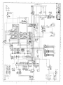
A2. P-864A Circuit Diagram ....................................................................... Appendix-3
A3. BC to BC System Setup ...................................................................... Appendix-5
A4. Korean Language Firmware ............................................................... Appendix-7
A5. Chinese/Japanese Language Firmware ............................................ Appendix-9
A6. Label Format Worksheets ................................................................. Appendix-11
A7. Dual Weight Range Notice ................................................................ Appendix-19
Contents - ii
BC-3000 • Service Manual • Rev. 1
HARDWARE SECTION
Chapter 1. Introduction
1
INTRODUCTION
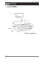
1.1 MAIN COMPONENTS
BC-3000 • Service Manual • Rev. 1
1-1
Chapter 1. Introduction
1.2 CHARACTERISTICS
■ 16-Bit microprocessor
The BC-3000 scale is equipped with a 16-bit microprocessor unit (V-40) which enables processing of large
quantities of data.
■ E2ROM
The use of E2ROM ensures that important data is not lost.
■ Resistance value and printing density settable via key entry
The thermal head resistance value as well as printing density can be set by key entry.
■ Settable sales mode
For supermarket specifications, there are operator and non-operator selections.
Differences from the AC-2000
• Data transmission to the IF-21FD is via I2NET (9P) instead of RS-232C used by the AC-2000.
• An inspection mode has been added. Verification can be made during totaling.
Mode Key Function
Enter the pass code (4 digits), then press MODE to change modes. If MODE is pressed without
entering a pass code, then normal operation mode is returned.
Pass Code
9000
8000
7000
6000*
5000*
Mode
Registration
Totals
Subtraction
Setting
Checking
*Fixed
1-2
BC-3000 • Service Manual • Rev. 1
Chapter 2. Set Up
2
SET UP
2.1 PARTS CHECK
Open the shipping carton and confirm the following:
•
•
No parts are missing.
No parts are damaged.
2.2 INSTALLATION SITE CHECK
Check that the installation site conforms to the following conditions:
•
•
•
•
•
•
Site is stable and level.
Scale will not be exposed to water or other liquids.
Scale will not be exposed to direct sunlight for long periods.
Scale will not be exposed to wind or strong vibration.
Installation site should be sufficiently spacious.
Dedicated, grounded circuit is available.
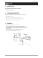
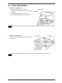
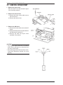
2.3 ASSEMBLY
Assemble the display components as follows:
1.
2.
3.
4.
5.
Thread the display connector cable through the display pole.
Attach display pole to the plastic display housing with 2 screws (M4).
Connect cables.
Attach the display to the main body with 2 screws (M4).
Cover the screws with the plastic screw caps.
BC-3000 • Service Manual • Rev. 1
2-1
Chapter 2. Set Up
2.4 SET UP SEQUENCE
1. Perform RAM clear sequence.
Insert the power plug into an outlet. Referring to Chapter S5 (Test Mode 2: RAM Clear), initialize all the
RAM data.
2. Set print format, label length and sales mode according to user's specifications.
Service manual reference sections:
• Print format setting
:
Chapter S5 (Test Mode7: Label Format)
• Label length setting
:
Chapter S4 (Setting Mode 1: Label Format)
• Sales mode setting
:
Chapter S5 (Test Mode 8: Sales Mode)
3. Register date and time.
Referring to the programming manual, enter the date and time.
4. Register PLU.
Referring to the programming manual, enter PLU data registration in Registration mode.
5. Perform print test.
Load a roll of labels or receipts, and confirm that printing is correct. Refer to Chapter S5 (Test Mode 3:
Thermal Head).
6. Perform totals clear.
Refer to the operation manual.
7. Back up data.
Back up the registration data on a floppy disk. Refer to Chapter S5 (Test Mode 99: Data Transmission.)
2-2
BC-3000 • Service Manual • Rev. 1
Chapter 3. Parts Disassembly & Replacement
3
PARTS DISASSEMBLY & REPLACEMENT
This chapter explains the procedures for disassembling and replacing the main components. Please be
careful not to drop or strongly impact fragile parts such as the display unit and circuit boards. Also, before
disassembly, be sure to turn off the power switch and unplug the power cord.
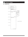
3.1 DISASSEMBLY VIEW AND PART NAMES
BC-3000 • Service Manual • Rev. 1
3-1
Chapter 3. Parts Disassembly & Replacement
Part Name Key
Part No.
Part Name
1*
PWB: P-864: CPU
2
PWB: P-830: A/D
3
PWB: P-865: Display
4*
Power Supply: Switching
5
Thermal head
6
Harness: S2: Thermal head
7
Panel: Keyboard
8
Label Sensor: AS
9
Harness: C3: Scale
10
Harness: C3: Power
11
Fuse: AS
12
Switch: Seesaw
13*
Harness: C3: Power cord
14
Power Supply: DC/DC
15
Harness: C3: I2NET
16
Harness: C2: Display 1
17
Harness: S2: DC/DC1
18
Timing Belt: XL (124 x L)
19*
Fuse: Glass tube
20
Motor: AS: Stepping
21
Harness: S3: Power
* These parts vary with country. (Only the software of PWB: P-864 varies; the board itself is
common to all countries.)
Note: Only the main parts are listed here. For a complete listing of parts and their corresponding parts
numbers, refer to the BC-3000 parts list.
3-2
BC-3000 • Service Manual • Rev. 1
Chapter 3. Parts Disassembly & Replacement
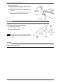
3.2 UPPER COVER REMOVAL
1. Remove the weigh platter.
1) Place the scale on a level surface.
Rotate the adjustment feet to level the scale if
necessary.
2) Unplug the power plug from its outlet.
3) Lift off the weigh platter, keeping it horizontal.
Note: When replacing the weigh platter, align the platter pins with the rubber inserts on the platter base.
2. Remove the platter base.
Remove the four attachment screws, then lift off the
platter base.
Note: After replacing the platter base, perform four corner adjustment (Refer to Section 5.5).
BC-3000 • Service Manual • Rev. 1
3-3
Chapter 3. Parts Disassembly & Replacement
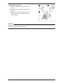
3. Remove display unit.
1) Remove the two screws (M4) that secure the
display pole to the main body.
2) Carefully lift up the display unit and disconnect
connector A.
3) Remove the two screws (M4) which secure the
plastic display housing to the display pole.
CAUTION!
In order to avoid damage to fragile components, be careful not to drop or strongly impact them.
4. Remove the operation keyboard panel.
1) Cut the base seal wire.
2) Remove base seal wire screw B.
3) Remove both screws C.
Note: The base seal wire is only used for countries
requiring a base seal. For other specifications, remove
only screws B & C.
CAUTION!
After the base seal wire is cut, it is necessary to have the scale re-inspected and the seal replaced. Never cut
the base seal unless required.
3-4
BC-3000 • Service Manual • Rev. 1
Chapter 3. Parts Disassembly & Replacement
5. Remove the upper case.
1) Lower the side panel in the direction of the
arrow.
2) Cut the seal wire, and remove the seal wire
screws.
3) Remove the four screws which secure the
upper case, then carefully lift the cover off
the main body.
CAUTION!
After the base seal wire has been cut, it is necessary to have the scale re-inspected and the seal replaced.
Never cut the base seal unless required.
BC-3000 • Service Manual • Rev. 1
3-5
Chapter 3. Parts Disassembly & Replacement
3.3 CIRCUIT BOARD REPLACEMENT
1. Remove the power unit.
1) Remove the two attachment screws from
the power unit located in the lower part of
the scale.
2) Remove connectors A & B.
2. Remove the main board.
1) Remove the attachment screw from the
main board.
2) Slide the main board toward you, and
remove connectors 3~8.
3. Remove the keyboard.
1) Remove connectors 9 and 10 located on
the main board beside the keyboard.
2) Peel off the keyboard starting from the
corner.
CAUTION!
If the keyboard is removed even once, it becomes
unusable. Never remove unless necessary.
4. Remove the A/D board.
Remove the A/D board referring to the
procedures described in Load Cell
Replacement section of this manual (Section
3.5).
3-6
BC-3000 • Service Manual • Rev. 1
Chapter 3. Parts Disassembly & Replacement
3.4 DISPLAY UNIT REPLACEMENT
Replace display unit.
1) Carefully remove the cover.
2) Remove the four screws which secure the
display unit.
CAUTION!
• To avoid damage to the cover, open it slowly and carefully.
• Avoid touching the display unit.
BC-3000 • Service Manual • Rev. 1
3-7
Chapter 3. Parts Disassembly & Replacement
3.5 LOAD CELL REPLACEMENT
1. Remove the upper cover.
Refer to Section 3.2 of this manual for upper
cover removal procedure.
2. Remove the load cell unit.
1) Remove the three screws which secure
the load cell unit.
2) Remove the load cell unit.
3. Remove the A/D board.
1) Remove the screw which secures the A/D
board.
2) Slide the A/D board from its plastic bracket
and disconnect Connector A.
3) Remove the load cell output cable
(soldered in five places).
CAUTION!
• The load cell output cable has five soldered
points. When replacing be sure that the wires
are in the correct order.
• After replacing the load cell unit, perform a fourcorner test. (Reference: Section 5.5 of this
manual)
3-8
BC-3000 • Service Manual • Rev. 1
Chapter 4. Electronic Configurations
4
ELECTRONIC CONFIGURATIONS
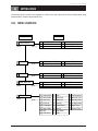
4.1 CONNECTOR CONFIGURATION
BC-3000 • Service Manual • Rev. 1
4-1
Chapter 4. Electronic Configurations
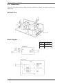
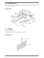
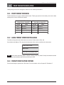
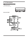
4.2 POWER UNIT
The power unit performs efficient voltage conversion, stabilizes low voltage, and supplies power to the
various units.
External View
Block Diagram
4-2
CN 1
SLS 100P
1
AC100 to 115V
3
AC100 to 115V
BC-3000 • Service Manual • Rev. 1
Chapter 4. Electronic Configurations
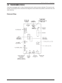
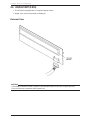
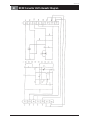
4.3 MAIN BOARD (P-864)
This board is equipped with a 16-bit microprocessor and is used to process scale data. The board is multilayered, and its high precision construction is designed to reduce electrical impedance, electrical noise, and
static electricity.
External View
BC-3000 • Service Manual • Rev. 1
4-3
Chapter 4. Electronic Configurations
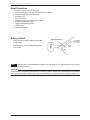
Board Functions
• Control of overall unit via CPU (V40)
*EPROM (Program memory) 4 Meg type (2) are installed
• Process weight data from A/D board
• Key data input
• Price calculation
• Display of weight, price and unit price data
• Label advance motor output
• Thermal head printing output
• I2NET output
• Label sensor input
Battery Switch
A lithium memory backup battery is included
in these units.
After installation, make sure the battery switch
is set to ON.
Note: This scale uses a rechargeable lithium battery. Normal charge is 3.6V. Battery switch is set to ON at
time of shipment from factory.
CAUTION!
There is danger of explosion if this battery is incorrectly replaced. Replace only with the same or equivalent
type recommended by the manufacturer. Discard used batteries according to the manufacturer's instructions.
4-4
BC-3000 • Service Manual • Rev. 1
Chapter 4. Electronic Configurations
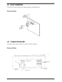
4.4 A/D BOARD (P-830)
The A/D board converts analog weight data from the load cell into digital data, and performs automatic span
control and zero compensation.
External View
4.5 KEYBOARD
This is a panel type keyboard.
A flexible cable connects it to the main keyboard (CN9 and CN10).
External View
BC-3000 • Service Manual • Rev. 1
4-5
Chapter 4. Electronic Configurations
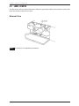
4.6 DISPLAY UNIT (P-856)
• The BC-3000 is equipped with a 7-segment display module.
• Weight, price, and unit price data are displayed.
External View
CAUTION!
• The display modules are made of glass so care should be taken not to touch or impact the units.
• Do not remove the connectors with the power ON.
4-6
BC-3000 • Service Manual • Rev. 1
Chapter 4. Electronic Configurations
4.7 DC/DC CONVERTER
The DC/DC converter transfers the voltage supplied to the display board.
External View
4.8 CONNECTOR BRACKET
Includes the power switch, power cord, fuse, and I2NET connectors.
External View
BC-3000 • Service Manual • Rev. 1
4-7
Chapter 4. Electronic Configurations
4.9 LABEL SENSOR
The label sensor utilizes a photo-interrupter to detect the gap between labels, and functions to ensure that
labels are printed correctly one at a time.
External View
Note: See Section 5.5 for adjustment procedures.
4-8
BC-3000 • Service Manual • Rev. 1
Chapter 5. Thermal Head
5
THERMAL HEAD
5.1 OVERVIEW
This 448 dot thermal head is specifically intended for use with label printers.
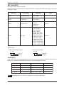
5.2 SPECIFICATIONS
Specification Sheet
Type
LH3124I (Double density thermal head) TDK
Overall dot count
448 dots
Dot pitch
0.135 (W) x 0.15mm (H)
Head resistance
R=528 to 672Ω
Required power
0.88 W/dot
Applied voltage
24 V
Maximum print width 60.5 mm
Resolution
188 dots/inch (7.4 dots/mm)
Print speed
2.8 inch/sec (70 mm/sec)
Configuration
BC-3000 • Service Manual • Rev. 1
5-1
Chapter 5. Thermal Head
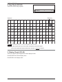
5.3 THERMAL HEAD ADJUSTMENT
If the printing surface of the thermal head and the top line of the print roller are not properly aligned, then
print quality across the width of the label will be poor.
First, print a test label, and if the clarity of the printed characters is not satisfactory, perform adjustment
according to the following procedure.
1) Loosen by 1/4 turn the two thermal head
attachment screws.
2) Manually adjust the position of the thermal
head so that the top line of the roller and
the thermal head print surface are aligned.
Print out another test label, and note the
print density. If not satisfactory, adjust the
position of the thermal head, then print
another label. Repeat until print density is
correct.
After adjustment, retighten the two
attachment screws.
Note: Thermal head is usually mounted flush
and parallel with the front edge of the mounting
plate.
CAUTION!
• Avoid touching the surface of the head. If touched, the surface should be wiped clean with a specialized
head cleaner formula.
• Before adjusting, first lower the print density. This will facilitate adjustment.
3) Set the thermal head resistance value.
Note: For setting method, refer to Chapter S5.2, Section 3, step C03-01.
4) Perform a label printing test.
Note: For test method, refer to Chapter S5.2, Section 3, step C03-03.
5-2
BC-3000 • Service Manual • Rev. 1
Chapter 5. Thermal Head
5.4 THERMAL HEAD CLEANING
If ink, glue, or other foreign matter adheres to the print surface of the thermal head, head conductivity will be
diminished, resulting in poor print quality.
(1) Wipe the surface of the head clean using a soft cloth moistened with a specialized head cleaning
formula.
CAUTION!
• Do not touch the surface of the head with hands or metallic objects.
• Never use thinner to clean the head as it may damage other parts of the scale.
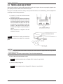
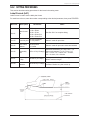
5.5 OTHER ADJUSTMENTS
Four limit bolts in the platter base function to prevent damage to the load cell from weight overload.
Four-corner adjustment is performed when the load cell is replaced or when external impact to the scale
necessitates it.
1. Four-corner adjustment
Place a weight equal to scale capacity (15kg/
30lb) plus 10% (1.5kg/3lb) on each corner of the
weigh platter base in rotation.
Rotate each of the four-corner adjustment screws
so that they just make contact with the limit bolts
when the weight is loaded [Gap (a) in diagram].
BC-3000 • Service Manual • Rev. 1
5-3
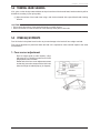
Chapter 5. Thermal Head
2. Label Sensor Adjustment
Label sensing is based on detection of variations in light between labels and the inter-label gaps. This
adjustment is performed to compensate for differences in light values which vary according to the type
of label paper used.
ADJUSTMENT METHOD
1) In test mode 4 (C04-00), check the values for the label and gap between labels.
Example: Sensor value for the gap between labels is 20 (backing paper only) and the sensor value for label
on backing paper is 220. These values are for example only and will vary depending on the label type.
2) In test mode 3 (C03-04), input the value calculated from the formula listed below based on the values for
the label and gap between labels.
*
Example:
220* (label) - 20 (gap)
= 100 (input value)
2
This input value (100) is the label and gap identification set value.
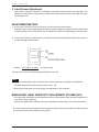
Note:
• If label on backing paper value is less than 200, perform adjustment procedure described below.
• The label and gap identification default setting value is 100.
• When using receipt paper for report printing, this adjustment is not necessary.
MAIN BOARD LABEL SENSITIVITY ADJUSTMENT VOLUME (VR1)
• The main board (P-864) label sensor adjustment volume (VR1) generally does not require adjustment (it
is set before factory shipment).
• Label sensor adjustment is ordinarily through the adjustment method steps 1 and 2 described above.
* The value for label with backing paper must be greater than 200. If the value is less than 200, label feed may
be inconsistent. Ideal value is between 240 and 250.
5-4
BC-3000 • Service Manual • Rev. 1
Chapter 6. Troubleshooting
6
TROUBLESHOOTING
This chapter describes periodic parts replacement and troubleshooting countermeasures for error messages.
6.1 PERIODIC PARTS REPLACEMENT (MTBF*)
The following parts need to be periodically replaced. *MTBF = Mean Time Between Failures
1. Thermal head
• Replacement period: When label advance distance reaches 30 km.
2. Display module (Display board)
• Normal life expectancy: Under normal usage conditions, 30,000 hours.
3. Print roller
• Replacement period: When label advance distance reaches 300 km.
BC-3000 • Service Manual • Rev. 1
6-1
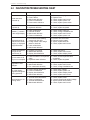
Chapter 6. Troubleshooting
6.2 MALFUNCTION TROUBLESHOOTING CHART
Error Condition
Scale cannot be
powered up.
Probable Causes
➀
➁
➂
➃
➄
Power plug mis-inserted.
Fuse is blown.
Main board defective
Power unit defective
Power switch defective
Test mode is entered ➀ Main board defective
at power up
➁ Keyboard defective
Dashes ("-") remain
in the weight display
➀
➁
➂
➃
Displayed weight is
different from actual
weight; or, displayed
weight fluctuates.
Countermeasures
➀
➁
➂
➃
➄
Reinsert power plug
Replace fuse
Check, replace main board
Check, replace power unit
Check, replace power switch
➀ Check, replace main board
➁ Check, replace keyboard
➀
➁
➂
➃
Check,
Check,
Check,
Check,
➀ Four-corner screw making
contact with limit bolt
➁ Foreign matter under weigh
platter or load cell
➂ Load cell defective
➃ Main board defective
➀
➁
➂
➃
Perform four-corner test
Remove foreign matter
Adjust, replace load cell
Check, replace main board
Certain segments do
not light or are
continuously lit.
➀ Program not running
➁ Main board defective
➂ Display board defective
➀ Check connectors
➁ Check, replace main board
➂ Check, replace display board
Input to some or all
keys is not accepted.
➀ Loose connection on keyboard
cable
➁ Keyboard board defective
➀ Check, secure keyboard cable
connection
➁ Check, replace keyboard
Registration data
changes.
➀ Battery defective
➁ Main board defective
➂ Ext. noise/static electricity
➀ Replace battery
➁ Check, replace main board
➂ Check, change installation site
All of the display
segments extinguish
during operation
➀
➁
➂
➃
Power voltage fluctuations
Power unit defective
Display board defective
Main board defective
➀
➁
➂
➃
Check power voltage
Check, replace power unit
Check, replace display board
Check, replace main board
Partial printing or no
printing at all.
➀
➁
➂
➃
Thermal head cable defect
Power unit defective
Thermal head defective
Main board defective
➀
➁
➂
➃
Check, replace cable
Check thermal head applied voltage
Adjust replace thermal head
Check, replace main board
6-2
Load cell defective
External vibration
Main board defective
Power unit defective
replace
change
replace
replace
load cell
installation site
main board
power unit
BC-3000 • Service Manual • Rev. 1
Chapter 6. Troubleshooting
6.3 ERROR MESSAGES
Error Display
Cause
Solution
Err-02
Too many characters on one line in product
description.
Edit product description by removing excess
characters per line
Err-03
Too many characters on first line for POP
message to print.
Edit product description's first line by removing
excess characters.
Err-04
Too many characters on one line in Extra
message.
Edit Extra message by removing excess
characters per line
Err-06
Too many characters on one line in Reg. Code.
Edit Reg. Code by removing excess characters
Err-07
Too many characters on one line in Store
Name/Address
Edit Store Name/Address by removing excess
characters per line
Err-08
• End of label roll.
• Mis-threaded labels.
• Install new label roll.
• Re-thread labels.
Err-09
• Incorrect labels installed in scale.
• Label size settings are incorrect.
• Mis-threaded labels.
• Install correct labels.
• Check label size settings.
• Re-thread labels.
Err-10
Discount price is equal to or greater than the
original price.
Check the discount price registration.
Err-11
Internal database has become corrupted.
Perform memory clear.
Memory in "FAT" area has been corrupted.
Re-initialize all memory including RAM and
E2ROM
Malfunction in main program: does not start up.
• Check possible CPU board failure.
• Check firmware chips
Memory in E2ROM has been corrupted.
Re-initialize with E2ROM clear.
A/D board is disconnected or malfunctioning.
• Check A/D board cabling.
• Replace A/D board
Err-51
NV RAM (calibration data) in ND board has been
corrupted.
Recalibrate scale
Err-56
Scale is unstable or was turned on with some
object on the platter.
Remove internal/external cause of instability.
Err-57
Scale was turned on with some object on the
platter.
Remove all objects from the scale and then turn
on the power.
Err-66
Transaction results cannot be written in to
memory due to corruption of Totals area.
♦ Incorrect Memory clear procedure.
♦ Memory has become corrupted.
♦ Memory is full.
• Clear scale totals.
• Power scale off after RAM clear, do NOT
use RESET key.
• Perform RAM clear.
• Re-initialize E2ROM
Master BC-3000 cannot communicate with
satellite scale number "XX" during programming.
• Faulty cable connections.
• Satellite scale is turned off or set "off-line".
• Satellite scale has been removed from the
network.
•
•
•
•
Err-40
Err-42
Err-43
Err-50
online Err
no_XX
Check all cable connections.
Turn on satellite scale.
Reset satellite scale to "on-line".
Reprogram master BC-3000 to ignore missing
satellite scale
Note: To clear error message from display, press the CLR key.
BC-3000 • Service Manual • Rev. 1
6-3
Chapter 6. Troubleshooting
6-4
BC-3000 • Service Manual • Rev. 1
SOFTWARE SECTION
Chapter S1. Outline of Software
S1
OUTLINE OF SOFTWARE
S1.1 MEMORY MAP
BC-3000 • Service Manual • Rev. 1
S1 - 1
Chapter S2. Print Format Modification
S2
PRINT FORMAT MODIFICATION
Label printing area can be changed to conform to user's label specifications.
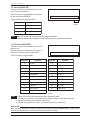
S2.1 PRINT FORMAT OVERVIEW
The BC-3000 has four types of default label formats. These types (shown in the table), serve as the base
settings which can be modified as needed.
Firmware B-0209D and higher
(Single-Range weighing)
Format
Label
Firmware B-0312 and higher
(Dual-Range weighing)
Format
Label
No. 1
60x44mm
No. 1
60x44mm
No. 2
64x47mm
No. 2
64x47mm
No. 3
64x85mm S.H.
No. 3
64x85mm S.H.
No. 4
64x37mm Non-UPC
No. 4
64x59mm S.H.
S2.2 LABEL FORMAT MODIFICATION RANGE
The label printing areas are divided into three sectors: Product name, Data, and
Store Name and address. The only print format sector which can be modified is the data sector.
Product name sector
Data sector
Store name and address sector
Note: Product name reference chapter: Chapter 4-Setting mode b01 (Label Format). Note that the number
of Store name and address and Product name lines is fixed.
S2.3 FORMAT MODIFICATION METHOD
Print format change is performed in Test mode. For more details, refer to Chapter S5-Test Mode 7.
BC-3000 • Service Manual • Rev. 1
S2 - 1
Chapter S3. Display Modules
S3
DISPLAY MODULE
S3.1 DISPLAY MODULE OVERVIEW
1)
2)
3)
4)
Root menu No.
Submenu No.
Selected item's number
Selected parameter's number
S3.2 ROOT AND SUBMENU SELECTION
This section describes the procedures for selecting the root and submenus.
■ Root Menu Selection Procedure
• Enter the number of the Root menu to be displayed, then press ↓.
• Press ↓ on the setting mode display to switch the root menus in sequence.
■ Sub Menu Selection Procedure
Press ↓ ENTER on the root menu display.
• Enter the number of the submenu to be displayed, then press ↓.
• Press ↓ to switch the submenus in sequence.
Note:
Press END to return to the mode displays.
BC-3000 • Service Manual • Rev. 1
S3 - 1
Chapter S4. Setting Mode
S4
SETTING MODE
The Setting mode is used to input settings to conform with user requirements. Enter Setting Mode using
password 6000, followed by the MODE key.
S4.1 MENU SCHEMATIC
Setting Mode
Sub Menus
01 Label Format Number
04 Field Title Print
05 Store Name. Address
06
07
09
(b02-**)
01 UPC Barcode Flag
02 10 Digit Flag
03 Bar Code Type
04 UPC Type
(b03-**)
01 Department Code
02 Group Code
03 UPC 8 Reference Data
04 UPC 13 Reference Data
(b04-**)
01 Register Code
02 Date Print
03 Pack Time
04
05
06
1 Label Format
(b01)
(b01-**)
2 Bar Code
(b02)
3 Code
(b03)
4 Initial Data Set
(b04)
8 PLU File
(b08)
(b08-**)
BC-3000 • Service Manual • Rev. 1
Commodity Line
Label Length +Gap
Sensor 2 Distance
Expire Time
Open Price
Forced Tare
02 Sales Mode 10 Tare
18 Extra Message
03 Mark Down
11 Date Print
22 Barcode Type
04 Unit Price
12 Shelf Life
23 Barcode Prefix
05 Fix Price
13 Use By
24 10 Digit Code
06 Fix Weight
14 Department
25 Open Price
07 Regi. Code
15 Group
27 Forced Tare
08 Qty
16 Item Code
09 Cost Price
17 POP
S4 - 1
Chapter S4. Setting Mode
11
Registrationn Select
(b11)
12
Total Mode Select
(b12)
13
S4 - 2
(b13-**)
02 Commodity Name
11 Group
04 Extra Message
12 Operator
06 Date/Time
17 Machine Number
07 Store Name, Address
19 On-Line Setup
08 Preset Key
21 Nutrition
09 PLU List
22 Price Change
01 Daily Total
03 Monthy Total
01 Registration Mode
02 Total Mode
03 Subtraction Mode
01 Default PLU Number
Default PLU
(b14)
10 Departmennt
(b12-**)
Password
(b13)
14
(b11-**)
01 PLU File
(b14-**)
BC-3000 • Service Manual • Rev. 1
Chapter S4. Setting Mode
S4.2 SETTING PROCEDURES
This section describes setting procedures for the items in the setting menu.
Label Format (b01)
Label Format is used to set the label print format.
For each item to be set, enter the number corresponding to the desired parameter, then press ENTER.
Menu No.
Description
Parameters
Notes
b01-01
Label format
No.
0: Receipt
1: 60 x 44mm
2: 64 x 47mm
3: 64 x 85mm S.H.
4: 64 x 59mm S.H
b01-04
Field title print
0: Title not printed
1: Title printed
Select if scale will print titles
b01-05
Store name,
Address
0: Not printed
1: Printed
Select if scale will print store name and address
b01-06
Commodity
Line
0.5 to 15.0 (0.5 steps)
Size three characters (15 x 30):1 line = 1.0
Size one characters (7 x 14): 1 line = 0.5.
0.5 = 2.7mm, 1.0 = 5.4mm, 2.0 = 10.8mm,
4.0 = 21.6mm, 9.0 = 48.6mm.
b01-07
Label Length
+ Gap
30.0-87.5 (0.1 steps)
Setting value: label length + label gap.
85mm maximum length.
b01-09
Sensor 2
Distance
50.0-150.0 (0.1 steps)
Gap sensor default = 107.5.
Increase: Farther out, print moves up.
See Sec S2-1 for complete listing
LABEL SENSOR
DISTANCE
BC-3000 • Service Manual • Rev. 1
S4 - 3
Chapter S4. Setting Mode
Bar Code (b02)
Bar Code is used to set bar code data.
Enter the number corresponding to the desired parameters, then press ENTER. After setting, confirm that
settings are correct.
Menu No.
Description
Parameters
Note
b02-01
UPC Barcode Flag
Enter 3 digits
*1
b02-02
10 Digit Flag
Enter 4 digits
*2
Bar Code Type
1: UPC 13
2: UPC 8
3: 10 Digit 13
4: 5 Digit 8
Default=1
UPC Type
1: UPC, CODE:5
2: UPC, CODE:6
3: EAN, CODE:6
4: UPC, PRICE:5
5: EAN9, CD:4, PR:5
6: EAN9, PR:4, C/P:5
7: EAN, CD:6, WT:4
Default=1
10: EAN, CD:4, WT:5
11: 0, COD:4, PR:5
12: MN:3, CD:2, PR:5
13: MN:2, CD:3, PR:5
14: FG:1, COD:6, PR:4
15: FG:1 , COD:6, PR:5
16: FG:1 , COD:6, WT:5
b02-03
b02-04
Default values:
*1 UPC Barcode Flag (3 digits)
2
*2 10 Digit Flag (4 digits)
02
49
49
UPC 13
UPC 8
10 digit 13
5 digit 8
Code (b03)
Code is used to set the codes for department, group, etc. for totals accumulations. Enter the code numbers
for each item, then press ENTER. After setting, confirm that settings are correct.
Menu No.
Description
Parameters
Note
b03-01
Department
Numeric entry: 2 digits
Default = 31
b03-02
Group
Numeric entry: 2 digits
Default = 42
b03-03
UPC 8 Reference
Numeric entry: 2 digits
Default = 42
b03-04
UPC 13 Reference
Numeric entry: 2 digits
Default = 45
Note: Item Code format = (step P01-16 in PLU programming)
S4 - 4
BC-3000 • Service Manual • Rev. 1
Chapter S4. Setting Mode
Initial Data Setting (b04)
Initial Data Setting is used to set reference values for PLU programming. Enter the number corresponding to
the desired parameters, then press ENTER. After setting, confirm that settings are correct.
Menu No.
b04-01
Description
Parameters
Register code Enter 3 digits
Notes
Not used in USA
Date Print
Select item by using →.
1: Prohibit -- Enter [0]
2: Pack Date -- Enter [0]
3: Expire Date -- Enter 3 digits (shelf life in days)
4: Both -- Enter 3 digits (shelf life in days)
Use by setting
[1] indicates
same day
Pack Time
Select item by using →.
1: Prohibit -- Enter [0]
2: Internal -- Enter [0]
3: Designated -- Enter 4 digits indicating time
Example: for 8 AM enter 800; for 2 PM, enter 1400.
Designated
time: 0-11 = AM.
12 to 23 = PM
b04-04*
Expire Time
Select item by using →.
1: Prohibit -- Enter [0]
2: Designated -- Enter 4 digits indicating time.
Example: for 8 AM, enter 800.
3: Relative -- Enter 4 digits
Example: To increase internal time by 3 hours enter
180. (Setting increments are 60)
Designated
time: 0-11 = AM.
12 to 23 = PM
b04-05
Open Price
Operators may change programmed prices.
1 = Prohibit, 2 = Allow
Default = 2
(Allow)
b04-06
Forced Tare
A tare weight must be entered before a label will print.
1 = Yes, 2 = No
Default = 2
(No)
b04-02 *
✝
b04-03†*✝
* The mode is steps b04-02 to b04-04 is selected by using →. The numeric values are then input followed
by ENTER.
✝ BC-3000 cannot program Pack Time and Expire Time by PLU.
BC-3000 • Service Manual • Rev. 1
S4 - 5
Chapter S4. Setting Mode
PLU File (b08)
PLU File is used to set which PLU items can be entered. Enter a parameter number for each item, then
press ENTER. After setting, confirm that settings are correct.
Note: All Item settings: 0 = Entry prohibit; 1 = Entry permit
MENU NO.
S4 - 6
SETTING DESCRIPTION
b08-02
SALES MODE
b08-03
MARK DOWN
b08-04
UNIT PRICE
b08-05
FIX PRICE
b08-06
FIX WEIGHT
b08-07
REGI CODE
b08-08
QTY
b08-09
COST PRICE
b08-10
TARE
b08-11
DATE PRINT
b08-12
SHELF LIFE
b08-13
USE BY
b08-14
DEPARTMENT
b08-15
GROUP
b08-16
ITEM CODE
b08-17
POP
b08-18
EXTRA MESSAGE
b08-22
BARCODE TYPE
b08-23
BARCODE PREFIX
b08-24
10 DIG. CODE
b08-25
OPEN PRICE
b08-27
FORCED TARE
BC-3000 • Service Manual • Rev. 1
Chapter S4. Setting Mode
Registration Select (b11)
Registration Select is used to prohibit or permit items to be accessed from the Registration menu. Enter the
desired parameter number for each item, then press ENTER. After setting, confirm that settings are
correct.
Note: All Item settings: 0 = Prohibit; 1 Permit
Menu No.
BC-3000 • Service Manual • Rev. 1
Setting Description
b11-01
PLU File
b11-02
Commodity Name
b11-04
Extra Message
b11-06
Date/Time
b11-07
Store Name
b11-08
Preset Key
b11-09
List
b11-10
Department
b11-11
Group
b11-12
Operators
b11-17
Machine No.
b11-19
On Line Set
b11-21
Nutrition File
b11-22
Price Change
S4 - 7
Chapter S4. Setting Mode
Total Mode Select (b12)
Total Mode Select is used to set totals mode parameters (Daily, or Monthly totals). Enter the number
corresponding to the desired parameter, then press ENTER. After setting, confirm that settings are correct.
Note: All Item settings: 0 = Prohibit, 1 = Permit
Menu No.
Setting description
b12-01
DAILY TOTAL
b12-03
MONTHLY TOTAL
Password (b13)
Password is used to change the password for Registration, Totals, and Subtraction modes. Enter the 4 digit
password then press ENTER.
Menu No.
Menu
Default Setting
B13-01
Registration
9000
B13-02
Totals
8000
B13-03
Subtraction
7000
Note: 1) The only value which cannot be entered is "6000."
2) The setup menu password cannot be changed from 6000.
Default PLU (b14)
Used to set the open PLU value. Enter the numbers (6 digits), then press ENTER.
Menu No.
b14-01
Setting Description
Open PLU
Entry Contents
Numeric entry (6 digits)
Note: To disable this feature, enter [0].
S4 - 8
BC-3000 • Service Manual • Rev. 1
Chapter S5. Test Mode
S5
TEST MODE
To access Test Mode: Turn on the power switch while holding down any key. Test Mode will be called up.
S5.1 MENU SCHEMATIC
Test Mode
1 Hardware Test
(C01)
Sub Menus
01
02
03
04
05
A/D Check
Key Check
Display Check
I2 Net Check
Program No.
(C01-**)
2 RAM Clear
(C02)
3 Thermal Head Setting
(C03)
01
02
03
All RAM Clear
E2 RAM Clear
Test Set
(C02-**)
01 Thermal Head
02 Print Usage in KM.
(C03-**)
01
02
03
I2 Net RAM CHeck
Loop Back Test
I2 Net Program No.
(C01-04-**)
03 Print Density
04 Label Sensor Adjust
4 Sensor Check
(C04)
5 Memory Check
(C05)
6 ROM Switch No. Select
(C06)
7 Label Fornat
(C07)
8 Sales Mode
(C08)
01 Mode
(C08-**)
10 Preset Function Key
(C10)
02 Transfer File
99 Data Send/Load
(C99)
BC-3000 • Service Manual • Rev. 1
03 Initialize Disk
(C99-**)
Asterisk(*)Key00 displays date/time
for approx. 1 second
Message Call
02 Extra
Up Key
03 Store Call Up Key
05 POP Set Key
06 Fixed Price Set Key
07 Save Key
08 Discount Key
09 Dollar ($) Key
10 Percent (%) Key
12 Fixed Weight
(C10-**)
01 Select IF 21 File No
02 Send
03 Receive
04 Verify
05 Delete
(C99-02-**)
S5 - 1
Chapter S5. Test Mode
S5.2 TEST MODE PROCEDURES
1
Hardware Test (C01)
1. A/D Check (C01-01)
This item is used to calibrate the scale.
4257
4257
A/D CONVERSION A/D CONVERSION
VALUE
INITIAL VALUE
SPAN ADJUSTMENT
10
AREA NO.
,"& )*
' $
- '
.
+
" )*
!" #
$ !
%
' -$
'
.
+
"#! &
'
(
S5 - 2
BC-3000 • Service Manual • Rev. 1
Chapter S5. Test Mode
(1) A/D Initial Value Setting
■ A/D Initial Value Setting
Press ZERO.
The A/D conversion value is displayed in
the unit price column. Check that the value
is 2000 ±1. If it is, perform span adjustment
as described below. If the value is not 2000
±1, press ZERO again.
■ Span adjustment
Place a 30 lb span weight on the weigh
platter. The A/D conversion value is
displayed in the weight column. Check that
the value is 30000 ±2. If it is, perform data
registration as described below. If not
30000 ±2, press TARE, remove the span
weight and perform A/D Initial Value Setting
again.
■ Data Registration
This operation writes data into E2 ROM.
Remove the span weight, then remove the
weigh platter. Press the switch as shown
in the diagram at right.
Note: Calibration data are stored on the
A/D board. The BC-3000 does not
require calibration if the main CPU
board is replaced.
CAUTION!
Do not use a screwdriver or other metal
tool to press the switch.
BC-3000 • Service Manual • Rev. 1
S5 - 3
Chapter S5. Test Mode
2. Key Check (C01-02)
This item is used to verify key data.
C01-02-00
1
0
Keyboard
Reset Key
1
2
3
4
5
6
7
8
9
10
11
12
13
14
15
16
17
18
19
20
21
22
23
24
25
26
27
28
31
32
33
34
35
36
37
38
39
40
41
42
43
44
45
46
47
48
49
50
51
52
53
54
55
56
57
58
59
60
61
62
63
64
65
66
67
68
69
70
71
72
73
74
75
76
77
78
79
80
81
82
83
84
85
86
87
88
89
90
91
92
93
94
95
96
97
98
99
100
101
102
103
104
105
106
107
108
109
110
111
112
113
114
115
116
117
118
119
120
30
Note: 1) Pressing RESET returns the display to the submenu.
2) If any keys do not work, check cable connections to the main board.
3) Once the membrane keyboard has been removed, it cannot be reused.
3. Display Check (C01-03)
This item is used to light all segments to check display function.
Press ENTER to start the display check.
Press END to exit display check.
S5 - 4
BC-3000 • Service Manual • Rev. 1
Chapter S5. Test Mode
4. I2NET Check (C01-04)
This item is used to verify that I2NET is functioning normally.
■ I2NET RAM Check (C01-04-01)
Press PRINT. Confirm that [PASS] is
displayed.
C01-04-01
PASS
C01-04-02
PASS
C01-04-03
id 4
■ Loop Back Test (C01-04-02)
Press PRINT. Confirm that [PASS] is
displayed.
■ I2NET Program No. (C01-04-03)
The I2NET Program No. (version) will be displayed.
5. Program No. (C01-05)
This item is used to display the ROM version number of the main board.
Press ↓ to switch between the main and
font ROM versions.
Step C01-05-00 = Main program
Step C01-05-01 = Font program
BC-3000 • Service Manual • Rev. 1
C01-05-00
b0312b
S5 - 5
Chapter S5. Test Mode
2
RAM Clear (C02)
1. All RAM Clear (C02-01)
This item is used to clear all data previously
programmed in the Registration Menu.
Press ZERO twice. When all RAM data
has been cleared, [PASS] is displayed.
C02-01
PASS
C02-02
PASS
C02-03
PASS
2. E2ROM Clear (C02-02)
This item is used to clear all configuration
changes programmed in the Setup Menu
and Test Menu.
Press ZERO twice. When E2ROM data
has been cleared, [PASS] is displayed.
Note: This step MUST be performed
when upgrading EPROM firmware chips.
3. Test Set (C02-03)
This item performs the same function as
steps C02-01 and C02-02 above with the
additional feature of creating the following
test data:
PLUs 1 through 10
Store Name/Address 1
Press ZERO twice. When Test Data has
been registered, [PASS] will be displayed.
S5 - 6
BC-3000 • Service Manual • Rev. 1
Chapter S5. Test Mode
3
Thermal Head (C03)
1. Head Resistance Value (C03-01)
This item is used to set the thermal head
resistance value.
Referring to the table below, enter the
resistance value according to the displayed
data.
C03-01
573
Enter the value, then press ENTER.
Resistance Value
Entry Value
528-545
537
546-563
555
564-581
573
582-600
591
601-618
609
619-636
627
637-654
645
655-672
663
Note: The resistance value can be automatically
"read" from the thermal head by pressing →.
2. Print Usage in KM (C03-02)
This item is used to display in kilometers
the amount of thermal head usage.
To clear usage data, enter [0] then press
ENTER.
C03-02
0.0
PLEASE NOTE!
• When replacing the thermal head be sure to clear the usage data.
• When returning a defective thermal head to the Service Center, please make a notation of the usage
distance on the repair invoice.
BC-3000 • Service Manual • Rev. 1
S5 - 7
Chapter S5. Test Mode
3. Print Density (C03-03)
This item is used to adjust the thermal head print
density.
Enter the density value 1 (light) - 9 (heavy), then
press ENTER.
C03-03
5
Press PRINT to print a test label to confirm
correct density.
Repeat until satisfactory.
PRINT SAMPLE
Note:
1) The default value is 5.
2) A value of "0" will cause unacceptably light/
spotty printing.
4. Label and Gap Identification
Setting (C03-04)
Set the label and gap identification value.
C03-04
100
C04-00
255
Input the value and press ENTER.
* For an explanation of the label and gap
identification set value, refer to "Label Sensor
Adjustment" (P.5-4 Section 5.5) under Chapter
5, "Other Adjustments."
4
Sensor Check (C04)
This item is used to confirm the current label gap
sensor value.
S5 - 8
BC-3000 • Service Manual • Rev. 1
Chapter S5. Test Mode
5
Memory Check (C05)
This item is used to confirm the amount of total
and remaining memory in kilobytes.
C05-00
6
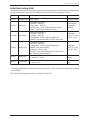
ROM Switch Number Select (C06)
128
110
Total Memory
Remaining
Memory
Note: ROM switches are used to change operational specifications and parameters.
Press → to select the ROM Switch No.
Enter the value and then press ENTER.
C06-01
0000
00
ROM SWITCH DATA
NUMBER
ROM Switch
Number
ROM Switch Function
13
Temporary date change type
15
FEED key function
16
VOID key function
1D
Selection of Unit Pricing
26*
Computer communications speed
28*
Wait time for PC acknowledgement after
transmission from scale
2A
RESET key operation
2D
On Line (BC to BC Master - Satellite
System)
2E
Satellite 2 connected (set in Master only)
2F
Satellite 3 connected (set in Master only)
30
Satellite 4 connected (set in Master only)
31
Satellite 5 connected (set in Master only)
3F*
Wait time before transmission from scale
to PC
0
ENTERED
VALUE
Setting Values
00 = Pack and Expire (default)
01 = Expire only
00 = blank label (default)
01 = reissue last label
00 = no label (default)
01 = print Void label
00 = $/kg
01 = $/100g and lb. (default)
00 = 9600 baud (default)
01 = 2400 baud, 02 = 4800 baud
03 = 9600 baud, 04 = 19200 baud
0 to 255 msec [0 to FF hex]
(default = 00)
00 = Enable (default)
01 = Disable
00 = Stand Alone (default)
01 = System
00 = No (default)
02 = Yes
00 = No (default)
03 = Yes
00 = No (default)
04 = Yes
00 = No (default)
05 = Yes
0 to 255 msec [0 to FF hex]
(default = 00)
* Available only in Dual-Range weighing scales with RS-232 enabled port.
(firmware B-0312 with "B" revision and higher)
BC-3000 • Service Manual • Rev. 1
S5 - 9
Chapter S5. Test Mode
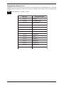
7
Label Format (C07)
This item is used to change the label printing
coordinates.
1. Enter the label format number (1 to 4), then
press PLU.
C07-01
2. Select X or Y coordinate using →
0
01
0324
0: X axis, 1: Y axis
0: X AXIS
1: Y AXIS
3. Select Print Field using ↓ or ↑ .
PRINT COORDINATE
FIELD
4. Enter the new coordinate value, then press
ENTER.
5. Press PRINT to print a test label.
6. Press END to return to the main Test Menu.
NOTES:
• To switch X and Y axis, press →.
• Reposition graduation is 1 = 0.1mm
LABEL
Y Axis
Base Points
X=0
Y=0
X Axis
Note: Refer to Appendix A6 for worksheets of all default label formats.
S5 - 10
BC-3000 • Service Manual • Rev. 1
Chapter S5. Test Mode
8
Sales Mode (C08)
1. Sales Mode (C08-01)
This item is used to set the sales mode most
suitable for the user's application.
Enter the number corresponding to the desired
mode, then press ENTER.
C08-01
1
SALES
MODE
Entry No.
1
ENTERED
NUMBER
Sales Mode
1
No SM Operator
2
SM Operator
BC-3000 • Service Manual • Rev. 1
S5 - 11
Chapter S5. Test Mode
10
Preset Function Key (C10)
Preset Function Key is used to set the functions
of preset keys PF1 to PF4.
Press ↓to select one of the function keys (PF1
to PF4). Enter the number corresponding to the
desired function, then press ENTER.
Preset Function
Key Locations
PF(1)
PF(2)
PF(3)
DATE
PF(4)
x
2
Entry No.
Function Name
0
DATE/TIME
1
----
2
MESSAGE
Call up ad message
3
STORE
Call up store name
4
----
5
POP
6
FIX PRICE
7
SAVE
8
DISCOUNT
Set discount (New Total Price)
9
-$
Set amount of price reduction
10
-%
Set percent of price reduction
11
----
----
2
Description
Displays Date/Time for 3 seconds
----
---Call up POP
Set fixed price
MULTIPLY
12
S5 - 12
C10-01
Save PLU
FIXED WEIGHT Set bakery weight in ounces
BC-3000 • Service Manual • Rev. 1
Chapter S5. Test Mode
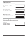
99
Data Send/Load (C99)
Data Send/Load is used for data communication with an IF-21FD interface unit.
Preparation
Before attempting to transmit data, make sure the BC-3000 is connected to the IF-21FD unit, and the scale
and IF-21FD power switches are ON.
Note: 1) All IF-21FD operations are performed from the BC-3000.
2) Before using a new floppy disk perform step 99-03 to format the disk.
(Use 2DD type disk only).
1. Transfer File (C99-02)
Transfer File is used to transmit individual data
files.
1.1 Select IF-21 file No. (C99-02-01)
Enter the number corresponding to the desired
file number (1 to 8), then press ENTER
C99-02-01
No 0
0
FILE
ENTERED
NUMBER NUMBER
Note: 1) Press → to see which files have been used previously.
2) Connect IF-21FD to the BC-3000 using the 9-pin cable supplied with the IF-21FD recorder.
3) Set IF-21FD DIP switches 2 and 5 down, all others are up.
4) For communications error codes, see chapter S6.
BC-3000 • Service Manual • Rev. 1
S5 - 13
Chapter S5. Test Mode
1.2 Send (C99-02-02)
This item is used to transmit data from the scale
to an IF-21FD interface unit.
Enter the number corresponding to the file(s) to
be sent, then press ENTER.
C99-02-02
No 0
0
To start transmission, press PRINT.
Entry No.
File Mode
1
All Files
2
Master File
3
E2 ROM File
ENTERED
NUMBER
Note: Master File contains all data programmed in Registration Mode.
E2ROM File contains all configuration setting changes made in Setup and Test Modes.
1.3 Receive (C99-02-03)
This item is used to receive data from an IF-21FD
interface unit.
Enter the number corresponding to the type of
file(s) to be received, then press ENTER.
C99-02-03
No 0
0
To start reception, press PRINT.
Entry No.
Function
Entry No.
Function
1
All Files
12
----
2
Master File
13
----
3
E2ROM File
14
Title File
4
Item Master*
15
Department*
5
Store Master*
16
Group*
6
----
17
----
7
Message Master*
18
----
8
Operator*
19
----
9
Press Key
20
Sub Total
10
Label Format
21
Nutrition File
11
Setup File
* File is compatible with other 3000 Series scales.
Note: 1) Master File contains all data programmed in Registration Mode.
E2ROM File contains all configuration setting changes made in Setup and Test Modes.
2) Master File contains file numbers 4-9 and 12-21.
3) E2ROM File contains file numbers 10 (Label Format) and 11 (Setup File).
IMPORTANT
When upgrading firmware or transferring files from one model to another, DO NOT load 11: SETUP FILE.
This file is incompatible and will cause unintended configuration settings.
S5 - 14
BC-3000 • Service Manual • Rev. 1
Chapter S5. Test Mode
1.4 Verify (C99-02-04)
This item is used to compare IF-21FD and BC3000 data.
Enter the number corresponding to the file(s) to
be compared, then press ENTER.
C99-02-04
No 0
0
To execute press PRINT.
Entry No.
Function
Entry No.
Function
1
All Files
12
----
2
Master File
13
----
2
3
E ROM File
14
Title File
4
Item Master*
15
Department*
5
Store Master*
16
Group*
6
----
17
----
7
Message Master*
18
----
8
Operator*
19
----
9
Preset Key
20
Sub Total
10
Label Format
21
Nutrition File*
11
Setup File
* File is compatible with other 3000 Series scales.
1.5 Delete (C99-02-05)
This item is used to delete a complete file from a
disk.
Press ZERO twice to delete the selected file.
OK is displayed after the file has been deleted.
C99-02-05
No 0
0
Select the file as shown in step 1.1 above.
Note:
BC-3000 • Service Manual • Rev. 1
S5 - 15
Chapter S5. Test Mode
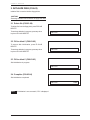
2. INITIALIZE DISK (C99-03)
Initialize Disk is used to initialize floppy disks.
CAUTION!
Executing Initialize Disk will delete all floppy disk data.
2.1 Delete file (C99-03-00)
To delete files from the floppy disk, press CHAR
DELETE.
To terminate deletion in progress, press any other
key than CHAR DELETE.
C99-03-00
2.2 OK to delete? (C99-03-02)
To execute disk initialization, press CHAR
DELETE.
To terminate deletion in progress, press any other
key than CHAR DELETE.
C99-03-02
2.3 OK to delete? (C99-03-03)
Disk initialization in progress.
C99-03-03
2.4 Complete (C99-03-04)
Disk initialization completed.
C99-03-04
PASS
Note: If initialization is not successful, "Err" is displayed.
S5 - 16
BC-3000 • Service Manual • Rev. 1
Chapter S6. IF-21FD Errors
S6
IF-21FD Errors
Refer to the table below when an error occurs during data transfer between the BC-3000 and the IF-21FD
Floppy Disk recorder.
Number
Display
Cause
Solution
2
Err 2
Floppy disk does not verify.
• Reload data to/from disk
• Create new master disk.
3
Err 3
• No disk in IF-21FD floppy disk
recorder.
• Bad IF-21FD disk drive.
• Install DS, DD floppy disk into
recorder
• Repair IF-21FD.
4
Err 4
5
Err 5
Cannot record to floppy disk because
it is write protected.
• Attempting to over write existing file
on floppy disk.
• Attempting to receive, verify, or
delete a nonexistent file on floppy
disk.
Move write protect tab on floppy disk
to correct position
• Select an unused file number
• Select an existing file number.
6
Err 6
IF-21FD floppy disk unit not
configured correctly.
• Check that only dip switches 2 and
5 are in the down position
• Check that the IF-21FD has the
latest firmware version (J-209N).
• Use 9-pin cable, not 25-pin cable.
7
Err 7
Parity error in communication
protocol.
Check scale CPU board.
8
Err 8
Floppy disk memory overflow.
• Restart with a blank floppy disk
• Erase unused files from floppy disk.
9
Err 9
Operation error.
Begin SAVE/LOAD procedure again
following correct procedure.
10
Err 10
Floppy disk format error.
Reformat floppy disk
66
Err 66
• Data on disk is corrupted.
• File is too large for scale memory.
• Scale memory is corrupted.
• Create new master disk
• Reduce file size and reload in to
scale's memory.
• Clear scale memory, reload disk.
• IF-21FD floppy disk recorder not
connected.
• Incorrect disk format.
• Power off scale and connect IF21FD floppy disk recorder
• Reformat floppy disk.
73
Err 73
BC-3000 • Service Manual • Rev. 1
S6 - 1
APPENDIX
Appendix
A1
DC/DC Converter Unit Schematic Diagram
BC-3000 • Service Manual • Rev. 1
Appendix - 1
Appendix
Appendix - 2
BC-3000 • Service Manual • Rev. 1
Appendix
A3
BC to BC System Setup
- BC-3000 Master/Satellite Communication (Firmware B-0209E & F-0194)
1. Overview
The BC-3000 has limited communication capabilities as compared to the AC-3000 series. Important
system considerations are listed here.
• PLU and price changes programmed at the master scale are instantly sent to each satellite scale that
is connected and set "on-line".
• If a satellite scale is not connected or is turned off or is set "off-line" the changes cannot be registered
into its memory.
• After programming, the master scale and all of the satellite scales contain identical PLU files in their
memory.
• The memory from the master scale cannot be downloaded or retransmitted to the memory of any
satellite scale.
• A maximum of five scales (one master plus four satellites) may be connected.
2. Set Up
Three separate memory areas of each BC-3000 scale must be configured to allow master-satellite
communications.
A. Test Menu
Step C06-01: ROM Switch [Access by powering up holding 1 key, 6, ENTER]
Set the on-line flag in all scales:
address 2D = 1
[Access by entering the address and pressing the → key]
Identify satellite scales (in master scale only)
address 2E = 2
address 2F = 3 (only if a third scale is connected)
address 30 = 4 (only if a fourth scale is connected)
address 31 = 5 (only if a fifth scale is connected)
B. Programming Menu
Step P17-01: Scale Number. [Access by password 9000, MODE, 17, ENTER]
Master Scale = 1
Satellite Scale = 2 to 5
Step P19-01: On-Line Mode. [Access by password 9000, MODE, 19, ENTER]
On-Line = 1
Off-Line = 0
BC-3000 • Service Manual • Rev. 1
Appendix - 5
Appendix
3. Hardware
A shielded 4-conductor twisted-pair cable is used to inter-connect the scales. The cable is terminated at
a 9-Pin Sub-Miniature D-Type male connector. Grounding is made at only one point - the master scale
chassis. At each satellite scale the ground wires are "daisy chained". The ground cable at the last scale
is not used.
Cable Pinout (straight through configuration)
Pair One
5 ---- 5 Data
9 ---- 9 Data
Pair Two
3 ---- 3 Signal Ground
7 ---- 7 Frame Ground
4. Programming
The following programming steps are available only at the master scale.
P01 - PLU Editing
P02 - PLU Name
P22 - Price Changes
5. Operation
A BC-3000 system scale operates the same as a normal stand alone machine.
6. Totals
A BC-3000 system scale operates the same as a normal stand alone machine. Totals must be taken at
each machine separately.
7. Errors
If a satellite scale is not communicating the master scale will display
On Line Error No X
where X is the satellite number that is not communicating.
8. Miscellaneous
If a satellite is to be removed from the system, reset its ROM switch number 2D = 0. See step 2A above.
Appendix - 6
BC-3000 • Service Manual • Rev. 1
Appendix
A4
Korean/English Language Firmware
(Firmware C-0840 & F-0208)
Operation
All operations remain the same as the standard BC-3000 except for the entry of text as described below.
1. Character Sizes available = 3 (large: 24 char. per line max., Korean and/or English)
2 (small: 24 char. per line max., Korean and/or English)
1 (ingredient: 48 char. per line, English only)
2. Korean vs. English characters
Press the BLANK key between NORMAL and REVERSE to switch between Korean and English
character entry.
Korean - triangle above SAVE is on (default)
- characters are entered as a four digit code (refer to KIS character list, available separately)
English - triangle above SAVE is off
- enter letters and numbers using the standard keyboard
- characters are not shown in the display
Korean and English characters may be mixed on the same line (except character size 1).
BC-3000 • Service Manual • Rev. 1
Appendix - 7
Appendix
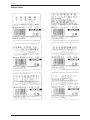
Sample Labels
Appendix - 8
BC-3000 • Service Manual • Rev. 1
Appendix
A5
Chinese/Japanese/English Language Firmware
(Firmware C-0877 & F-0218)
Operation
All operations remain the same as the standard BC-3000 except for the entry of text as described below.
1. Character Sizes available = 3 (large: 24 char. per line max., Chinese, Japanese, and/or English)
2 (small: 24 char. per line max., Chinese, Japanese, and/or English)
1 (ingredient: 48 char. per line, English only)
2. Chinese/Japanese vs. English characters
Press the BLANK key between NORMAL and REVERSE to switch between Chinese/Japanese and
English character entry.
Chinese/Japanese
- triangle above SAVE is on (default)
- characters are entered as a four digit code (refer to JIS character list, available separately)
English - triangle above SAVE is off
- enter letters and numbers using the standard keyboard
- characters are not shown in the display
Chinese, Japanese, and English characters may be mixed on the same line (except character size
1).
BC-3000 • Service Manual • Rev. 1
Appendix - 9
Appendix
Sample Labels
Appendix - 10
BC-3000 • Service Manual • Rev. 1
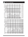
BC-3000 • Service Manual • Rev. 1
"Sell By" Fixed Price
"TOTAL PRICE" Legend
"Sell By..." Random Wt.
Single Pc. - (Fixed Pr.)
Single "PC" - (Fixed Pr.)
Price Including Tax
"AMOUNT TOTAL"
Transaction Number
"Pcs."
PLU Description
PLU Name 2
Weight
Total Price
PLU Number
Price before Discount
Markdown Line 1
Markdown Line 2
Discounted Price
Unit Price ($/lb)
Barcode
Pack Date
Expiration Date
Standard Function
05
03
04
00
08
00
09
07
02
13
13
13
14
00
21
21
11
11
12
12
06
49
62
63
8D
6B
90
Code
Value
New Value
Size
B-0209D-K-Fmt. 1
XYXYWidth Height Width Height
0000 0165
0153 0211
0010 0211
0149 0160
0297 0211
0321 0174
0456 0211
0367 0067
0486 0132
0430 0036
0430 0027
0430 0018
0430 0067
0000 0000
0156 0216
0224 0211
0367 0067
0375 0097
0545 0163
0375 0163
0008 0364
0008 0364
0016 0241
0016 0241
0016 0241
0016 0241
0405 0106
Old Value
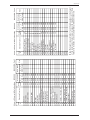
BC-3000
Ad Message 1
Sign
Sub-Total - Price
Sub-Total - Weight
Sub-Total - Pieces
Store Name/Address
Piece Count
"Pcs." Legend
"@ " Legend
@ count
"/ " Legend
@ /FOR Price
Total OZ Weight
Total "oz" Symbol
"( " Symbol
" ) " Symbol
LB Wt. inside ( )
"lb" symbol
OZ Wt. inside ( )
"oz" symbol
Standard Function
0E
0B
28
27
26
01
2C
2C
2B
2B
2B
2D
32
32
32
32
31
31
30
30
Code
Value
New Value
Size
B-0209D-K-Fmt. 1
XYXYWidth Height Width Height
9999 0000
0338 0052
0342 0067
0390 0211
0067 0051
0008 0465
0156 0216
0224 0211
0286 0211
0305 0216
0372 0211
0391 0216
0337 0166
0373 0156
0415 0166
0572 0166
0434 0166
0471 0156
0513 0166
0549 0156
Old Value
BC-3000
Note: The height values of the fields 21 and 33 are dependent on the
height of the text area. As the text area increases the height position of
these fields also increases, as do any data fields printed above the text.
28
29
30
31
32
33
34
35
36
37
38
39
40
41
42
43
44
45
46
47
48
49
50
Field
#
60mm x 44mm with Barcode
A6
1
2
3
4
5
6
7
8
9
10
11
12
13
14
15
16
17
18
19
20
21
22
23
24
25
26
27
Field
#
60mm x 44mm with Barcode
Appendix
Label Format Worksheets
Appendix - 11
Appendix - 12
1
2
3
4
5
6
7
8
9
10
11
12
13
14
15
16
17
18
19
20
21
22
23
24
25
26
27
Field
#
"Sell By" Fixed Price
"TOTAL PRICE" Legend
"Sell By..." Random Wt.
Single Pc. - (Fixed Pr.)
Single "PC" - (Fixed Pr.)
Price Including Tax
"AMOUNT TOTAL"
Transaction Number
"Pcs."
PLU Description
PLU Name 2
Weight
Total Price
PLU Number
Price before Discount
Markdown Line 1
Markdown Line 2
Discounted Price
Unit Price ($/lb)
Barcode
Pack Date
Expiration Date
Standard Function
64mm x 47mm with Barcode
05
03
04
00
08
00
09
07
02
13
13
13
14
00
21
21
11
11
12
12
06
49
62
63
8D
6B
90
Code
Value
New Value
Size
B-0209D-K-Fmt. 2
XYXYWidth Height Width Height
0008 0204
0162 0247
0018 0247
0157 0190
0305 0247
0321 0204
0472 0247
0375 0121
9999 0201
0438 0088
0438 0079
0438 0070
0438 0121
0000 0000
0156 0252
0224 0247
0375 0121
0410 0154
0553 0243
0379 0243
0016 0394
0016 0394
0024 0276
0024 0276
0024 0276
0024 0276
0415 0175
Old Value
BC-3000
Ad Message 1
Sign
Sub-Total - Price
Sub-Total - Weight
Sub-Total - Pieces
Store Name/Address
Piece Count
"Pcs." Legend
"@ " Legend
@ Count
"/" Legend
@ /For Price
Total OZ Weight
Total "oz" Symbol
"(" Symbol
")" Symbol
LB Wt. inside ( )
"lb" Symbol
OZ Wt. inside ( )
"oz" Symbol
Standard Function
0E
0B
28
27
26
01
2C
2C
2B
2B
2B
2D
32
32
32
32
31
31
30
30
Code
Value
New Value
Size
B-0209D-K-Fmt. 2
XYXYWidth Height Width Height
9999 0000
0348 0112
0351 0121
0398 0247
0075 0082
0013 0495
0156 0252
0224 0247
0286 0247
0305 0252
0372 0247
0391 0252
0337 0211
0373 0202
0415 0211
0572 0211
0434 0211
0471 0202
0513 0211
0549 0202
Old Value
BC-3000
Note: The height values of fields 21 and 33 are dependent on the height
of the text area. As the text area increases the height position of these
fields also increases, as do any data fields printed above the text.
28
29
30
31
32
33
34
35
36
37
38
39
40
41
42
43
44
45
46
47
48
49
50
Field
#
64mm x 47mm with Barcode
Appendix
BC-3000 • Service Manual • Rev. 1
1
2
3
4
5
6
7
8
9
10
11
12
13
14
15
16
17
18
19
20
21
22
23
24
25
26
27
Field
#
BC-3000 • Service Manual • Rev. 1
"Sell By Fixed Price"
"TOTAL PRICE" Legend
Ad Message 1
Sign
Sub-Total - Price
Sub-Total - Weight
"Sell By..." Random Wt.
Single Pc. - (Fixed Pr.)
Single "PC" - (Fixed Pr.)
PLU Description
PLU Name 2
Weight
Total Price
PLU Number
Price before Discount
Markdown Line 1
Markdown Line 2
Discounted Price
Unit Price ($/lb)
Barcode
Pack Date
Expiration Date
Standard Function
05
03
04
00
08
00
09
07
02
13
13
13
14
00
21
21
06
49
62
63
8D
6B
90
0E
0B
28
27
Code
Value
64mm x 85mm, with Safe Handling
XYXYWidth Height Width Height
0008 0177
0162 0228
0018 0228
0157 0171
0305 0228
0321 0169
0472 0228
0375 0076
0494 0156
0438 0043
0438 0034
0438 0025
0438 0076
0000 0000
0156 0232
0224 0228
0016 0774
0016 0774
0024 0256
0024 0256
0024 0256
0024 0256
0415 0126
9999 0000
0348 0067
0351 0076
0398 0228
New Value
Old Value
Size
B-0209D-K-Fmt. 3
BC-3000
Sub-Total - Pieces
Safe Handling Panel
Store Name/Address
Piece Count
"Pcs." Legend
"@ " Legend
@ Count
"/" Legend
@ /For Price
Total OZ Weight
Total "oz" Symbol
"(" Symbol
")" Symbol
LB Wt. inside ( )
"lb" Symbol
OZ Wt. inside ( )
"oz" Symbol
Standard Function
26
8C
01
2C
2C
2B
2B
2B
2D
32
32
32
32
31
31
30
30
Code
Value
New Value
Size
B-0209D-K-Fmt. 3
XYXYWidth Height Width Height
0075 0082
0013 0640
0008 0874
0156 0232
0224 0228
0286 0228
0305 0232
0372 0228
0391 0232
0337 0189
0373 0180
0415 0189
0572 0189
0434 0189
0471 0180
0513 0189
0549 0180
Old Value
BC-3000
Note: The height values of fields 17 and 30 are dependent on the height
of the text area. As the text area increases the height position of these
fields also increases, as do any data fields printed above the text.
28
29
30
31
32
33
34
35
36
37
38
39
40
41
42
43
44
45
46
47
48
49
50
Field
#
64mm x 85mm, with Safe Handling
Appendix
Appendix - 13
Appendix - 14
1
2
3
4
5
6
7
8
9
10
11
12
13
14
15
16
17
18
19
20
21
22
23
24
25
26
27
Field
#
"Packed On" Fixed Pr.
'Sell By" Legend
"TOTAL PRICE" Legend
Ad Message 1
Sign
Sub-Total - Price
"Packed On" Weighed
Pack Date
Expiration Date
Unit Price ($/lb)
Weight
Total Price
PLU Number
Price before Discount
Markdown Line 1
Markdown Line 2
Discounted Price
Single Pc. - (Fixed Pr.)
Single "PC" - Fixed Pr.)
Price Including Tax
"AMOUNT TOTAL"
Transaction Number
"Pcs."
PLU Description
PLU Name 2
Standard Function
03
04
08
09
07
02
13
13
13
14
21
21
11
11
12
12
06
49
62
63
8D
6B
90
90
0E
0B
28
Code
Value
64mm x 37mm without Barcode
New Value
Size
B-0209D-K-Fmt. 4
XYXYWidth Height Width Height
0008 0141
0008 0045
0162 0141
0297 0141
0372 0067
0162 0036
0436 0036
0436 0027
0436 0018
0436 0067
0120 0105
0167 0105
0372 0067
0375 0097
0545 0163
0375 0163
0013 0294
0013 0294
0016 0171
0016 0171
0016 0171
0016 0171
0016 0075
0411 0171
9999 0000
0338 0045
0348 0067
Old Value
BC-3000
Sub-Total - Weight
Sub-Total - Pieces
Store Name/Address
Piece Count
"Pcs." Legend
"@ " Legend
@ Count
"/" Legend
@ /For Price
Total Ounce Weight
Total "oz" Symbol
"(" Symbol
")" Symbol
LB Weight inside ( )
"LB" Symbol
OZ Weight inside ( )
"OZ" Symbol
Standard Function
27
26
01
2C
2C
2B
2B
2B
2D
32
32
32
32
31
31
30
30
Code
Value
New Value
Size
B-0209D-K-Fmt. 4
XYXYWidth Height Width Height
0390 0141
0151 0051
0013 0394
0120 0105
0167 0105
0206 0105
0220 0105
0267 0105
0280 0105
0153 0076
0190 0067
0213 0076
0356 0076
0232 0076
0268 0067
0297 0076
0333 0067
Old Value
BC-3000
Note: The height values of fields 17 and 30 are dependent on the height
of the text area. As the text area increases the height position of these
fields also increases, as do any data fields printed above the text.
28
29
30
31
32
33
34
35
36
37
38
39
40
41
42
43
44
45
46
47
48
49
50
Field
#
64mm x 37mm without Barcode
Appendix
BC-3000 • Service Manual • Rev. 1
1
2
3
4
5
6
7
8
9
10
11
12
13
14
15
16
17
18
19
20
21
22
23
24
25
26
27
Field
#
BC-3000 • Service Manual • Rev. 1
"Sell By" Fixed Price
"TOTAL PRICE" Legend
"Sell By..." Random Wt.
Weight
Total Price
PLU Number
Price before Discount
Markdown Line 1
Markdown Line 2
Discounted Price
Single Pc. - (Fixed Pr.)
Single "PC" - (Fixed Pr.)
Price Including Tax
"AMOUNT TOTAL"
Transaction Number
"Pcs."
PLU Name 2
Unit Price ($/lb)
Store Name/Address
PLU Description
Barcode
Pack Date
Expiration Date
Standard Function
01
06
05
03
04
00
08
00
09
07
02
13
13
13
14
21
21
11
11
12
12
49
62
63
8D
6B
90
Code
Value
60mm x 44mm UPC Barcode Label
XYWidth Height
0008 0465
0008 0364
0000 0165
0153 0211
0010 0211
0149 0160
0297 021 1
0321 0174
0456 0211
0367 0067
0486 0132
0430 0036
0430 0027
0430 0018
0430 0067
0156 0216
0224 0211
0367 0067
0375 0097
0545 0163
0375 0163
0008 0364
0016 0241
0016 0241
0016 0241
0016 0241
0405 0106
Old Value
XWidth
YHeight
New Value
B-0312B
Ad Message 1
Sign
Sub-Total - Price
Sub-Total - Weight
Sub-Total - Pieces
Piece Count
"PCS" Legend
"@ " Legend
@ count
"/" Legend
@ /FOR Price
Total OZ Weight
Total "oz" Symbol
"(" Symbol
")" Symbol
LB Wt. inside ( )
"lb" symbol
OZ Wt. inside ( )
"oz" symbol
Standard Function
0E
0B
28
27
26
2C
2C
2B
2B
2B
2D
32
32
32
32
31
31
30
30
Code
Value
XYWidth Height
9999 0000
0338 0052
0342 0067
0390 0211
0067 0051
0156 0216
0224 0211
0286 0211
0305 0216
0372 0211
0391 0216
0337 0166
0373 0156
0415 0166
0572 0166
0434 0166
0471 0156
0513 0166
0549 0156
Old Value
XWidth
YHeight
New Value
Format 1
Note: The height values of fields 1 and 2 are dependent on the height
of the text area. As the text area increases the height position of these
fields also increases, as do any data fields printed above the text.
Note: Navigation- use ↑↓ keys to select FIELD NUMBERS
- use →key to select X (Width) or Y (Height).
28
29
30
31
32
33
34
35
36
37
38
39
40
41
42
43
44
45
46
47
48
49
50
Field
#
BC-3000-dual range
Appendix
Appendix - 15
Appendix - 16
1
2
3
4
5
6
7
8
9
10
11
12
13
14
15
16
17
18
19
20
21
22
23
24
25
26
27
Field
#
"Sell By" Fixed Price
"TOTAL PRICE" Legend
"Sell By..." Random Wt.
Single Pc. - (Fixed Pr.)
Single "PC" - (Fixed Pr.)
Price Including Tax
"AMOUNT TOTAL"
Transaction Number
"PCS"
PLU Name 2
Unit Price ($/lb)
Weight
Total Price
PLU Number
Price before Discount
Markdown Line 1
Markdown Line 2
Discounted Price
Store Name/Address
PLU Description
Barcode
Pack Date
Expiration Date
Standard Function
01
06
05
03
04
00
08
09
07
02
13
13
13
14
00
21
21
11
11
12
12
49
62
63
8D
6B
90
Code
Value
64mm x 47mm UPC Barcode Label
XYWidth Height
0013 0495
0016 0394
0008 0204
0162 0247
0018 0247
0157 0190
0305 0247
0472 0247
0375 0121
9999 0201
0438 0088
0438 0079
0438 0070
0438 0121
0000 0000
0156 0252
0224 0247
0375 0121
0410 0154
0553 0243
0379 0243
0016 0394
0024 0276
0024 0276
0024 0276
0024 0276
0415 0175
Old Value
XWidth
YHeight
New Value
B-0312B
Ad Message 1
Sign
Sub-Total - Price
Sub-Total - Weight
Sub-Total - Pieces
Piece Count
"PCS" Legend
"@ " Legend
@ Count
"/" Legend
@ /For Price
Total OZ Weight
Total "oz" Symbol
"(" Symbol
")" Symbol
LB Wt. inside ( )
"lb" Symbol
OZ Wt. inside ( )
"oz" Symbol
Standard Function
0E
0B
28
27
26
2C
2C
2B
2B
2B
2D
32
32
32
32
31
31
30
30
Code
Value
XYWidth Height
9999 0000
0348 0112
0351 0121
0398 0247
0075 0082
0156 0252
0224 0247
0286 0247
0305 0252
0372 0247
0391 0252
0337 0211
0373 0202
0415 0211
0572 0211
0434 0211
0471 0202
0513 0211
0549 0202
Old Value
XWidth
YHeight
New Value
Format 2
Note: The height values of fields 1 and 2 are dependent on the height
of the text area. As the text area increases the height position of these
fields also increases, as do any data fields printed above the text.
Note: Navigation- use ↑↓ keys to select FIELD NUMBERS
- use →key to select X (Width) or Y (Height).
28
29
30
31
32
33
34
35
36
37
38
39
40
41
42
43
44
45
46
47
48
49
50
Field
#
BC-3000 - dual range
Appendix
BC-3000 • Service Manual • Rev. 1
1
2
3
4
5
6
7
8
9
10
11
12
13
14
15
16
17
18
19
20
21
22
23
24
25
26
27
Field
#
BC-3000 • Service Manual • Rev. 1
"Sell By" Fixed Price
"TOTAL PRICE" Legend
Ad Message 1
Sign
Sub-Total - Price
"Sell By..." Random Wt.
Single Pc. - (Fixed Pr.)
Single "PC" - (Fixed Pr.)
PLU Name 2
Unit Price ($/lb)
Tare Weight
Weight
Total Price
PLU Number
Price before Discount
Markdown Line 1
Markdown Line 2
Discounted Price
Store Name/Address
PLU Description
Barcode
Pack Date
Expiration Date
Standard Function
01
06
05
03
04
00
08
22
09
07
02
13
13
13
14
00
21
21
49
62
63
8D
6B
90
0E
0B
28
Code
Value
Old Value
XYWidth Height
0008 0874
0016 0774
0008 0207
0162 0258
0018 0258
0157 0171
0297 0258
0326 0049
0456 0258
0375 0106
0494 0186
0438 0073
0438 0064
0438 0055
0438 0106
0000 0000
0156 0262
0224 0258
0016 0774
0024 0256
0024 0286
0024 0256
0024 0286
0415 0156
9999 0000
0348 0097
0351 0106
64mm x 85mm Safe Handling Label
XWidth
YHeight
New Value
B-0312B
Sub Total - Weight
Sub-Total - Pieces
Safe Handling Panel
Piece Count
"PCS" Legend
"@ " Legend
@ Count
"/" Legend
@ /For Price
Total OZ Weight
Total "oz" Symbol
"(" Symbol
")" Symbol
LB Wt. inside ( )
"lb" Symbol
OZ Wt. inside ( )
"oz" Symbol
Standard Function
27
26
8C
2C
2C
2B
2B
2B
2D
32
32
32
32
31
31
30
30
Code
Value
XYWidth Height
0398 0258
0075 0112
0013 0640
0156 0262
0224 0258
0286 0258
0305 0262
0372 0258
0391 0262
0337 0219
0373 0210
0415 0219
0572 0219
0434 0219
0471 0210
0513 0219
0549 0210
Old Value
XWidth
YHeight
New Value
Format 3
Note: The height values of fields 1 and 2 are dependent on the height
of the text area. As the text area increases the height position of these
fields also increases, as do any data fields printed above the text.
Note: Navigation- use ↑↓ keys to select FIELD NUMBERS
- use →key to select X (Width) or Y (Height).
28
29
30
31
32
33
34
35
36
37
38
39
40
41
42
43
44
45
46
47
48
49
50
Field
#
BC 3000-dual range
Appendix
Appendix - 17
Appendix - 18
1
2
3
4
5
6
7
8
9
10
11
12
13
14
15
16
17
18
19
20
21
22
23
24
25
26
27
Field
#
"Sell By" Fixed Price
"Sell By..." Random Wt.
Single Pc. - (Fixed Pr.)
Single "PC" - (Fixed Pr.)
Price Including Tax
"AMOUNT TOTAL"
Transaction Number
"PCS"
PLU Name 2
Unit Price ($/lb)
Tare Weight
Weight
Total Price
PLU Number
Price before Discount
Markdown Line 1
Markdown Line 2
Discounted Price
Store Name/Address
PLU Description
Barcode
Pack Date
Expiration Date
Standard Function
01
06
05
03
04
00
08
22
09
07
02
13
13
13
14
00
21
21
11
11
12
12
49
62
63
8D
6B
Code
Value
Old Value
XYWidth Height
0008 0622
0008 0540
0000 0135
9999 0211
0449 0211
0149 0160
0129 0184
0318 0000
0000 0184
0379 0067
0486 0169
0437 0036
0437 0027
0437 0018
0437 0067
0000 0000
0000 0184
0067 0180
9999 0067
9999 0097
9999 0163
9999 0163
9999 0250
9999 0241
9999 0241
9999 0241
9999 0241
64mm x 59mm Safe Handling Label
XWidth
YHeight
New Value
B-0312B
"TOTAL PRICE" Legend
Ad Message 1
Sign
Sub-Total - Price
Sub-Total - Weight
Sub-Total - Pieces
Piece Count
"PCS" Legend
"@ " Legend
@ count
"/" Legend
@ /FOR Price
Total OZ Weight
Total "oz" Symbol
"(" Symbol
")" Symbol
LB Wt. inside ( )
"lb" symbol
OZ Wt. inside ( )
"oz" symbol
Standard Function
90
0E
0B
28
27
26
2C
2C
2B
2B
2B
2D
32
32
32
32
31
31
30
30
Code
Value
XYWidth Height
9999 0106
9999 0000
9999 0052
0342 0067
0000 0184
0067 0051
0000 0184
0067 0180
0129 0180
0148 0184
0216 0180
0233 0184
0349 0135
0386 0124
0426 0135
0584 0135
0445 0135
0484 0124
0526 0135
0561 0124
Old Value
XWidth
YHeight
New Value
Format 4
Note: The height values of fields 1 and 2 are dependent on the height
of the text area. As the text area increases the height position of these
fields also increases, as do any data fields printed above the text.
Note: Navigation- use ↑↓ keys to select FIELD NUMBERS
- use →key to select X (Width) or Y (Height).
28
29
30
31
32
33
34
35
36
37
38
39
40
41
42
43
44
45
46
47
48
49
50
Field
#
BC-3000-dual range
Appendix
BC-3000 • Service Manual • Rev. 1
Appendix
A7
NEW BC-3000 Dual Range Scale Notice
Due to popular demand from our customers the BC-3000 has been enhanced to provide dual weight range
readings. From 0 to 15 pounds weight readings increment by 0.005 lb. From 15 to 30 pounds weight readings
return to a standard 0.01 lb. The added accuracy in the lower weight range will provide greater cost benefits
to your customers by more closely tracking actual tare weights and product weights.
You should be aware of the following issues resulting from the BC-3000 upgrade to dual range weight
readings.
1. Revised Label Formats The four standard label formats have been altered. The format worksheets can
be found in Appendix A6 and are posted in the Distributor section of the Rice Lake/Ishida web site at:
http://www.ishidaretail.com.
The four formats are:
• 60mm x 44mm, standard
• 64mm x 47mm, standard
• 64mm x 85mm, Safe Handling
• 64mm x 59mm, Safe Handling
2. Using old Label Formats Label formats that were created on single range BC-3000 scales must be
modified for use with a dual range BC-3000. After loading them from an IF-21FD recorder the decimal
point position of any weight fields must be moved one place to the left. This procedure is straight forward
and listed here:
1.
2.
3.
4.
5.
6.
7.
8.
9.
10.
Enter the Test Menu (C00) [Power ON holding the “1” key].
Enter the Label Format step (C07-00) [“7”, ENTER].
Select the label format 1~4 (C07-01) [format number, PLU key].
Enter “Flag Change” area (C07-01 01) [SIZE].
Use the RIGHT ARROW to move across to column 17 (decimal point location).
Use the DOWN ARROW to move down to the Weight field (refer to worksheets to determine
Weight field number.).
Reduce the decimal point value by one.
Example: Current value is 02, input 01, press ENTER.
Print a test label to verify there are now three digits after the decimal point in the Weight field.
Make similar changes to the Tare Weight and SubTotal Weight fields.
Press END, turn the scale off.
3. Existing PLU Files PLU files from single range BC-3000 scales are not fully compatible with the new
dual range BC-3000. Tare weight values are low by a factor of ten.
Example
1. Old tare is 0.04. Dual range BC-3000 reads this as 0.004. This is then rounded up to 0.005 (dual
range BC-3000 counts by 0.005 therefore the last digit must be either a “0” or “5”.
2. Old tare is 0.12. Dual range tare is 0.012, rounded down to 0.010
4. Networking BC-3000 dual range and single range scales cannot be networked together. Tare weight
values will not transfer correctly resulting in the decimal point being off by one position. In other words,
the tare value will be either ten times too large or too small.
If a new BC-3000 will be added to an existing network, this should be specified at the time the order is
placed.
BC-3000 • Service Manual • Rev. 1
Appendix - 19
ISHIDA CO., LTD.
44 SANNO-CHO SHOGOIN SAKYO-KU
KYOTO, 606 JAPAN
PHONE: (075) 771-4141
FACSIMILE: (075) 751-1634
TELEX: 05422065 SCALES J
CABLE ADD: “SCALES”KYOTO
IW512P1003