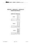
1
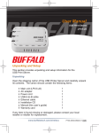
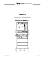
PERSEO
Service manual
PERSEO
ANAESTESIA WORKSTATION
SERVICE MANUAL
P.N.:DU5028130
1
REV.3.0
PERSEO
Service manual
GENERAL INDEX
SERVICE MANUAL..................................................................................................................................1
1. USE OF THE SERVICE MANUAL .......................................................................................................3
1.1. Users of manual.............................................................................................................................3
1.2. General Notes................................................................................................................................3
1.3. Safety Notes ..................................................................................................................................4
WARNINGS..............................................................................................................................................4
2. GENERAL MAINTENANCE PROCEDURES .......................................................................................6
2.1. General Information .......................................................................................................................6
3. WORKSTATION DESCRIPTION .........................................................................................................7
3.1 General Information ......................................................................................................................7
3.2 Structure .......................................................................................................................................8
3.3 AM5000/3 – AM5000/5 anaesthesia module ..................................................................................9
3.4 Breathing System..........................................................................................................................12
3.4.1. OPEN-SEMICLOSED VERSION (NON REBREATHING -REBREATHING) ........................12
3.4.2. OPEN VERSION (NON REBREATHING) .............................................................................14
3.5. VM 2000 lung ventilator ............................................................................................................15
3.5.1. A) MODE Section...............................................................................................................17
3.5.2. B) RATE Section................................................................................................................18
3.5.3. C) INSP FLOW - PEEP Section.........................................................................................19
3.5.4. D) TIDAL VOLUME Section ...............................................................................................20
3.5.5. E) AIRWAY PRESSURE section .......................................................................................21
3.5.6. F) OXYMETER Section......................................................................................................22
3.5.7. G) BELLOW section...........................................................................................................23
3.6. RM 3000 Breathing Monitor ......................................................................................................24
3.7. Vaporizer ..................................................................................................................................26
3.8 Operating Principal .......................................................................................................................27
4. ASSEMBLY OF VALVE GROUP (BREATHING SYSTEM)................................................................33
5. CALIBRATION AND TEST.................................................................................................................43
5.1 Valve Group (Breathing System) .................................................................................................43
5.2 Final Test ......................................................................................................................................47
6. PNEUMATICS....................................................................................................................................49
6.1. Pneumatic Diagram Of Perseo ....................................................................................................49
6.2 Pneumatic Components ..............................................................................................................51
6.3 Pneumatic Diagram vm200 ........................................................................................................51
6.4 Pneumatic Diagram AM5000/3 – AM5000/5.................................................................................53
7. ELECTRONICS..................................................................................................................................54
Warning
SIARE is used throughout this manual as an abbreviation for
SIARE HOSPITAL SUPPLIES S.r.l.
Via Giulio Pastore, 18 - 40056 Crespellano (BO) – ITALY
Tel.: 051/969802
Fax: 051/969101
Manufacturer of the equipment described in this manual
P.N.:DU5028130
2
REV.3.0
PERSEO
Service manual
1. USE OF THE SERVICE MANUAL
1.1. Users of manual
This manual is strictly for use by SIARE technicians or qualified technicians authorized by SIARE:
The technician authorized by SIARE has available the appropriate tools and spare parts and is trained with
regards to the safety of the product.
SIARE declines all responsibility with regards to technical assistance to the unit without formal authorization
of SIARE.
The correct and safe use for the patient and the operator of the unit, requires the knowledge of the
instructions and advice written in this manual and the User’s manual.
1.2. General Notes
! placed near an instruction, calls the reader’s attention to important information regarding
The symbol
the safety of the patient and operator.
The manual describes the unit and its operation with the help of electrical and pneumatic diagrams.
!
-
The following manuals are an integral part of this manual:
PERSEO’S User Manual
VM 2000 Service Manual
RM 3000 Service Manual
AM5000/3-AM 5000/5 Service Manual
The technician should have available a copy of the User’s manual and should known its contents before
performing any of the operations described in this manual.
P.N.:DU5028130
3
REV.3.0
PERSEO
Service manual
1.3. Safety Notes
WARNINGS
The unit has been designed and is manufactured in conditions that guarantee the quality of the product and
its components, in order to ensure the maximum level of reliability and the safety of the patient and the
operator.
Therefore its safety is guaranteed only if it is used as per the instructions contained in this manual and the
User’s manual which is an integral and unseparable part of the product documentation for the technical
assistance.
For safety reasons, it is necessary to strictly follow the scheduled maintenance described in the User’s
manual.
The maintenance and the replacement of any parts has to be performed by authorized SIARE service
dealers and only original SIARE parts or parts checked by SIARE should be used.
SIARE is not civically or criminally liable in the following cases:
1)
Use in conditions and for reasons not stated or prescribed in this manual.
2)
Lack or omission of scheduled maintenance as described in this manual.
3)
Maintenance performed by personnel not authorized by SIARE.
4)
Use of non original spare parts or spare parts not checked and approved by SIARE.
5)
Connection with equipment that is not in compliance with relevant directives in effect for safety for
the indicated use.
P.N.:DU5028130
4
REV.3.0
PERSEO
Service manual
!
Do not use the equipment in the presence of flammable gases.
In order to avoid risk of explosion this unit should not be used in the in the presence of flammable
anaesthetic gases such as ether of ciclopropane. This unit can operate only with anesthetics that are not
flammable as per the directive relative to the electrical safety of the anaesthesia units.
!
Do not connect the unit to the patient using conductive antistatic tubes.
Due to the fact that this machine cannot be used with flammable anaesthetic agents, such as ether or
ciclopropane, the use of antistatic patient tubes is not necessary. Since the use of antistatic tubes can cause
burns when using surgical equipment at high frequencies, their use is not allowed in any administration with
this equipment.
!
The unit is not approved for use in areas with danger of explosion.
The unit cannot be used in the presence of explosive gases.
Before connecting the unit with other electrical equipment not described in this manual,
check with the manufacturer.
The electrical connection of the unit should be made according to the instructions in this
manual in order to eliminate the danger of electric shock to the patient or operator due to an
improper installation.
Regarding electro-medical equipment’s general safety, it is important to follow all rules regarding the
interaction between the equipment and the patient, the operator and the nearby environment.
In order to ensure proper and safe use of the equipment it is crucial to follow the instructions in this manual
and the User’s manual and pay attention to the notes furnished in this User’s manual.
In order to use this equipment, it is vital to know all the instructions in this manual.
The equipment should be inspected and the maintenance performed by SIARE authorized personnel every 6
(six) months. All maintenance performed by SIARE authorized personnel is recorded in the equipment’s
maintenance log.
Every repair should be performed by SIARE authorized personnel. Siare is not liable for direct or indirect
damage to people or things, due to technical assistance by personnel non-authorized by SIARE or improper
use of the equipment, that is to say a use not described in the User’s manual or technical manual.
In order to repair equipment that is malfunctioning, has defects or is broken, the operator should contact
SIARE or its authorized local service dealer. It is important, when requesting service, to specify the model
and serial number of the equipment.
Use only the recommended accessories.
The use of other accessories is authorized only by a written authorization from SIARE as per the safety
directives in effect.
The equipment’s operation is authorized only in areas that conform to the safety directives in effect.
P.N.:DU5028130
5
REV.3.0
PERSEO
Service manual
2. GENERAL MAINTENANCE PROCEDURES
2.1. General Information
!
In order to ensure the safety of the patient and the operator, the unit should undergo an inspection and test
after 800 hours of use or every 6 months, whichever comes first. The inspection and test require a specific
knowledge of the unit, and therefore have to be made by specially trained SIARE authorized personnel.
The anesthetist or doctor is responsible for the ordinary maintenance of the unit, as described in this chapter.
Cleaning, disinfecting, sterilization and replacement of parts should be done as per the instructions in the
user’s manual in order to avoid damage to the equipment that could also endanger the safety of the patient
and operator.
The components used have been selected after technical and comparative tests in the designing phase of
the machine.
Furthermore, the same components are always tested during the manufacturing cycle in order to obtain the
maximum level of safety and reliability for the operator and patient.
Therefore whenever a part needs to be replaced, it must be an original spare part, which has been checked
and tested by SIARE.
SIARE assumes responsibility for all provisions of the law, if the unit is used and maintained as per the
instructions in this manual and the technical manual. The Technical Assistance Report, signed by the
authorized SIARE technician, is proof of the completion of the scheduled maintenance.
P.N.:DU5028130
6
REV.3.0
PERSEO
Service manual
3. WORKSTATION DESCRIPTION
3.1 General Information
The PERSEO unit is composed of modules.
In its full optional configuration, it is composed of the following sections:
F
E
B
C
D
A
A
B
C
D
E
F
P.N.:DU5028130
Structure
AM5000/3 – AM5000/5 anaesthesia module
Breathing System
VM 2000 lung ventilator
RM 3000 breathing monitor
Anaesthesia vaporizer
7
REV.3.0
PERSEO
Service manual
3.2 Structure
F
G
I
E
H
A
D
L
C
B
Front view
A
B
C
D
E
F
G
H
I
L
M
Back view
Aluminum and laminated plastic structure
Antistatic pivoting wheels (the front wheels are equipped with a pedal brake)
Removable drawer
Instrument shelf
Work shelf
Monitor shelf
Siaretex base for rapid connection of vaporizers (optional), Selectatec type and compatible with
vaporizer with interlock system (connection for second vaporizer is optional)
Support bracket for “Breathing System” valve unit
Support bracket for patient circuit arm
Support for 5.3 Lt. Cylinders
auxiliary guide for the assembly of optional accessories
P.N.:DU5028130
8
REV.3.0
PERSEO
Service manual
3.3 AM5000/3 – AM5000/5 anaesthesia module
AM5000/3 – AM5000/5 regulates the supply and concentration of the gas mixture (Air, O2, N2O), and also
supplies it to the anaesthetic gas vaporizer.
It also allows the selection of the gas mixture to be supplied (Air-O2, or N2O-O2) and the enrichment (with
oxygen) of the supplied gas mixture for emergencies. The AM5000/3 – AM5000/5 is also equipped with the
MIX-LIFE device that guarantees a minimum of 25% oxygen in all open-tap conditions.
By using the three gauges located on the front panel, the medical gases supply pressure coming from the
central gas installation can be continuously controlled (precision ± 10%).
The flowmeters permit the measurement of the flow the of the corresponding gases with a precision of ±
10% of the displayed value or ± 1% of the bottom of the scale, by choosing the highest of the two values.
S T U
I
L
M
N
O
P
Q
V
R
Front view AM5000/3
I
L
M
N
OXYGEN supply gauge.
NITROUS OXIDE supply gauge.
AIR supply gauge.
Selector switch for AIR / NITROUS OXIDE. This safety device:
avoids the contemporaneous supply of air and nitrous oxide
only the selected gas will be available on the flowmeters.
O OXYGEN BY-PASS key. By pressing this key pure oxygen is released into the anaesthesia circuit with
a flow of approximately 60 l/min.
P OXYGEN flow regulator for fresh gases. It opens counter-clockwise.
Q NITROUS OXIDE flow regulator for fresh gases. It opens counter-clockwise.
The opening of this regulator automatically supplies a flow of oxygen of about 25% of the total mixture.
The flow of oxygen can be viewed on flowmeter (S). This safety device (MIX LIFE) avoid the incorrect
administration of hypoxic mixtures.
R AIR flow regulator for fresh gases. It opens counter-clockwise.
S OXYGEN flowmeter (Max flow 12 l/min). In the model for low flows, there is a second flowmeter with a
lower scale of 1 liter.
T
NITROUS OXIDE flowmeter (Max flow 12 l/min).. In the model for low flows there is a second
flowmeter with a lower scale of 1 liter.
U AIR flowmeter (Max flow 12 l/min).
V Selector switch for the exit of fresh gases (BREATHING SYSTEM or TO AND FRO).
For more details about the scales and the precision of the gauges and flowmeters, please refer to appendix
A «Technical data».
P.N.:DU5028130
9
REV.3.0
PERSEO
Service manual
Avoid closing the regulators too tightly, so not as to wear or damage them.
The indicated flow value should be read at the upper level of the rim of the flowmeter
indicator when it rotates. If there is not rotation ask for technical assistance.
Reading level
!
CUT-OFF ALARM. If the anaesthesia module sounds a whistle, it means that the pressure
of the oxygen is too low. Immediately take action to reset the oxygen pressure. If the
pressure of the main system is not available, use the oxygen gas cylinder for emergencies.
G
F
A
B
C
D
E
I
H
Back View
A
B
C
D
E
F
G
H
I
OXYGEN inlet from the main medical gas installation.
NITROUS OXIDE inlet from the main medical gas installation.
COMPRESSED AIR inlet from the main medical gas installation.
OXYGEN inlet from the cylinder’s pressure reducer.
NITROUS OXIDE inlet from the cylinder’s pressure reducer.
AIR/OXYGEN outlet for the supply of the lung ventilator, of the active scavenging system and the
tracheal aspiration unit.
In optimal conditions these connector supply COMPRESSED AIR.
If there is no COMPRESSED AIR or there is not enough pressure, the unit automatically switches the
distribution to OXYGEN.
These connectors are supplied standard with the machine if the relative accessories are in use
Emergency OXYGEN outlet.
Exit of fresh gases connector for TO and FRO.
FRESH GAS outlet for the Breathing System. (please refer to chapter 4.4 “Breathing System Assembly”
in the PERSEO’S user manual)
P.N.:DU5028130
10
REV.3.0
PERSEO
Service manual
!
DANGER OF FIRE! Do not connect devices that are not explicitly certified to function with
PURE OXYGEN to outlets F and G.
!
Do not make connections to the main medical gas installation or the gas cylinders before
reading section 4.2 “MEDICAL GAS CONNECTION” in the PERSEO’S user manual.
P.N.:DU5028130
11
REV.3.0
PERSEO
Service manual
3.4 Breathing System
3.4.1. OPEN-SEMICLOSED VERSION (NON REBREATHING -REBREATHING)
It is the device that takes fresh gases towards the patient and that collects the expired gases towards the
CO2 absorber and then to the lung ventilator to be supplied to the patient. The fresh gases supplied by the
AM5000 anaesthesia module are also added to the Breathing System.. With this cirucit it is also possible, by
simply rotating the selector (V), to change the system into an OPEN or NON-REBREATHING. The manual
ventilation is possible directly from the valve group or with the TO AND FRO system.
T
T
Q
P
A
D
U
E
F
S
O
N
S
B
Q
R
V
C
M
L
H
U
I
H
A
B
C
D
E
F
G
H
I
L
C
A
D
E
F
G
Structure of the Breathing System.
Selector form AUTOMATIC SPONTANEOUS or MANUAL (AUT.SPONT-MAN) ventilation.
Inspiratory line connection to the patient circuit.
Water trap
Expiratory flow sensor.
Expiratory line connection to the patient circuit.
Mounting bracket for the flow sensor.
Reservoir balloon connection.
Connection for fresh gas input hose from AM 5000 anaesthesia module.
Ambient air aspiration valve. Opens automatically when the quantity of fresh gases in the breathing
circuit is not enough to guarantee the set current volume.
Connection to lung ventilator.
Inspiratory valve plastic cover
Oxygen sensor. It measures the O2 concentration of the inspiratory mix, therefore right before the
mix reaches the patient.
Expiratory valve.
APL valve. It regulates the maximum airway pressure during manual ventilation. The pressure
increases by turning the knob of the valve clockwise and lowers by turning it counter-clockwise.
The
range of regulation is from approximately 2 to 30 cmH2O.
M
N
O
P
Q
!
During manual ventilation, the airway pressure can go over the limit set on the lung
ventilator. The pressure limit depends on the regulation of the APL valve.
P.N.:DU5028130
12
REV.3.0
PERSEO
Service manual
R
S
T
mounting bracket of APL valve.
Soda lime canister, capacity 1.5 Kg.
Locking cap for closing and lifting the canister.
U
V
Connection for exit of used breathing gases ( ! to be connect to scavenging system).
REBREATHING or NON REBREATHING selector.
P.N.:DU5028130
13
REV.3.0
PERSEO
Service manual
3.4.2. OPEN VERSION (NON REBREATHING)
It is the device that takes fresh gases towards the patient and that collects the expired gases towards the
disposal. The fresh gases form the AM5000 modules are also collected on the Breathing System The
manual ventilation is possible only with the TO AND FRO system.
P
O
N
L
A
D
E
F
C
V
C
M
D
E
A
H
F
I
H
A
C
D
E
F
G
H
I
L
G
P
Structure of the Breathing System.
Inspiratory line connection to the patient circuit.
Flow sensor connection to the expiratory line.
Expiratory flow sensor.
Exspiratory line connection to the patient circuit
Mounting bracket for the flow sensor.
Reservoir balloon connection.
Connection for fresh gas input hose from AM 5000 anaesthesia module.
Ambient air aspiration valve. Opens automatically when the quantity of fresh gases in the breathing
circuit is not enough to guarantee the set current volume.
Connection to lung ventilator.
Inspiratory valve plastic cover
Oxygen sensor. It measures the O2 concentration of the inspiratory mix, therefore right before the
mix reaches the patient.
Expiratory valve.
V
Connection for exit of used breathing gases ( !
M
N
O
P.N.:DU5028130
to be connect to scavenging system).
14
REV.3.0
PERSEO
3.5.
Service manual
VM 2000 lung ventilator
VM2000 lung ventilator is the device that mechanically controls the breathing activity of the patient when the
patient is being automatically ventilated. Other than the regulations of the patient’s ventilation mode, the
VM2000 also enables checking the airway pressure and oxygen concentration of the patient’s gas mixture.
L
F
H
G
I
E
C
D
B
A
M
Back view
A Main ON/OFF switch
B Safety fuses
!
ATTENTION!. The specification of the fuse to be used is indicated on the identification tag(I).
Never use fuses with a different specification.
C
D
E
F
G
H
I
Inlet for main power cable.
Inlet for auxiliary power (MAX 6 Ampere).
Inlet for AIR - OXYGEN (3.5 Bar ± 0.75).
Outlet for power cable for RM3000 monitor.
Outlet for synchronizing cable for RM3000 monitor.
Cooling fan.
Identification tag.
The following specifications are displayed:
- MODEL
- SERIAL NUMBER
- POWER SUPPLY
- POWER FREQUENCY
- POWER CONSUMPTION
- FUSE SPECIFICATION
L Battery safety fuse (5A T).
M equipotential connector.
P.N.:DU5028130
15
REV.3.0
PERSEO
E
F
G
Service manual
D
C
B
A
Front View
A
B
C
D
E
MODE section for setting ventilation modes of the lung ventilator
RATE section for setting breathing rate.
FLOW-PEEP section for setting inspiratory flow and the positive end expiratory pressure (PEEP).
TIDAL VOLUME section for setting tidal volume for the breathing act.
AIRWAY PRESSURE section for setting minimum and maximum alarm limit for the airway pressure,
therefore check the maximum airway pressure, that the VM2000 can reach when in operation.
F OXYMETER section for measurement and alarm for airway gas concentration.
G BELLOW section
P.N.:DU5028130
16
REV.3.0
PERSEO
Service manual
3.5.1. A) MODE Section
1
A
Operating modes of the lung ventilator can be selected by turning the knob of the MODE section (1).
The selection of a operating mode is indicated when its corresponding LED turns ON.
OPERATING MODES:
POSITION
OFF
STAND-BY
MANUAL - SPONT
CONTROL
CONTROL + ASS
ASS
SIMV
IMV
P.N.:DU5028130
DESCRIPTION
Machine off displays the status of the power supply when one of the following
operating modes are selected. With the main power supply the OFF led is on and it
is green. When the unit is supplied by battery and the battery is charged, the led
becomes orange. When the battery is low the led becomes red and the audible
alarm comes on.
Stand-by (pause) mode for setting parameters.
Manual and spontaneous ventilation mode
Controlled ventilation mode
Controlled-Assisted ventilation mode
Assisted ventilation mode
Synchronized intermittent mandatory ventilation mode
Non-synchronized intermittent mandatory ventilation mode
17
REV.3.0
PERSEO
Service manual
3.5.2. B) RATE Section
1
2
3
4
6
5
9
8
7
B
1 Breathing rate regulation knob (RATE) from 5 to 90 BPM (breaths per minute).
When the machine is turned ON the preset breathing rate is 16 BPM.
2 Display for the set breathing rate (RATE).
3 Selection key for the Inspiration:Expiration ratio (I:E). When the machine is turned ON the I:E rate us
reset at 1:2.
In order to change the I:E ratio, this key (3) must be pressed and let go.
The following I:E ratios can be selected: 1:2 > 1:3 > 1:4 > 2:1 > 3:1 > 4:1 > 1:1.
4 Display for the set I:E ratio.
5 Regulation knob for the sensor sensibility that recognizes the patient’s spontaneous breathing (TRIGGER
EFFORT) used to synchronize the ventilator.
The sensibility can be adjusted from -10 to + 10 cmH2O.
!
6
7
8
9
ATTENTION!. The sensibility has to be set at 2 or 3 cmH2O lower than the PEEP level.
If the set sensibility is equal to or higher than the PEEP level, the trigger only activates at
the end of each breathing cycle, hyperventilating the patient.
Yellow LED indicates trigger activation.
Regulation knob for SIMV rate(SIMV RATE).
Display for set SIMV rate (SIMV RATE).
LED for SIMV TIME. The length of time of the lit LED corresponds to the time period which the ventilator
waits to synchronize the forced breath with a spontaneous breath.
If at the end of this time period the patient has not breathed, the ventilator starts a forced breath
(minimum rate guaranteed).
P.N.:DU5028130
18
REV.3.0
PERSEO
Service manual
3.5.3. C) INSP FLOW - PEEP Section
3
2
1
1
Positive end expiratory pressure (PEEP) regulation knob.
!
2
C
ATTENTION!. Inserting PEEP during automatic ventilation requires care, because it determines
the rise of the maximum and medium pressure of the airway pressure.
The airway pressure alarms should always be set correctly.
Inspiratory flow and pressure regulator.
When ventilating with a high tidal volume or pressure the set tidal volume may not be completely
administered ( the indicator of the tidal volume does not reach “0”). In this case the regulation knob (2)
should be turned counter-clockwise (+) until the tidal volume indicator reaches “0”.
During normal ventilation conditions the selection knob should be completely turned clockwise (-).
P.N.:DU5028130
19
REV.3.0
PERSEO
Service manual
3.5.4. D) TIDAL VOLUME Section
3
2
1
2
3
1
C
Selection key to increase tidal volume.
Selection key to decrease tidal volume.
LED for setting tidal volume with a scale from 0 to 1500 ml.
The indicator is connected with the bellow and therefore it will move towards the left (0 ml.) during the
inspiratory cycle, and towards the right in the expiratory cycle.
The set tidal volume is indicated when the bellow is paused (all to the right = end of expiration).
It is recommended to regulate the tidal volume when the machine is on STAND-BY mode. It can also be
set during ventilation, but the set tidal volume is displayed only when the bellow is at the end of its run, to
the right.
P.N.:DU5028130
20
REV.3.0
PERSEO
Service manual
3.5.5. E) AIRWAY PRESSURE section
E
1
3
5
6
2
4
8
7
In this section the instantaneous airway pressure is measured and the following alarms are set:
1
Electronic airway pressure gauge. This analogic gauge enables the display of pressures from -10 to
100 cmH2O.
2
Regulation of low pressure alarm limit. Should be set lower than the measured (about 80%) so as to
sense a decrease in pressure due to a leak or disconnection from the patient circuit.
3
Low pressure LED (visual) alarm. It is activated with the audible alarm when the pressure does not
reach the set lower limit for at least 3 breathing cycles.
4
Regulation of high pressure alarm limit. Should be set higher than the measured so as to sense an
increase in pressure due to, for example, an airway obstruction or an overdose of volume.
5
High pressure LED (visual) alarm. It is activated with the audible alarm when the pressure goes above
the set upper limit. If this reoccurs for more than 5 breathing cycles the light becomes solid.
6
High and low pressure alarm reset. This key silences the pressure audible alarms for 30 seconds. After
30 seconds, if the alarm condition is still present, the alarm sounds again.
If the alarm condition no longer exists, the alarm resets itself automatically.
7
Maximum pressure limit regulation. This regulation sets the maximum limit of the airway pressure.
When this limit is reached the inspiratory phase stops and the expiratory phase starts (pressure limit
operation). When the pressure limit is activated, the set tidal volume is not completely
administered.
8
Pressure limit LED (visual) alarm. It is activated when the pressure limit is reached.
P.N.:DU5028130
21
REV.3.0
PERSEO
Service manual
3.5.6. F) OXYMETER Section
6
1
5
4
3
F
7
2
This device continuously measures the percentage of oxygen in the breathing mixture and checks that the
concentration is within the set limits. The sensor is made of a galvanized cell mounted on the inspiratory
valve of the Breathing System.
The oxymeter section is composed of:
1
Oxygen concentration display. The oxygen concentration value is displayed.
connected, two dashes (--) will appear on the display.
2
Calibration knob. Calibration enables the correction of the value read from the oxygen sensor by testing
a mixture with a known oxygen concentration.
The calibration procedure is described on section 5.3.
3
Minimum oxygen concentration alarm limit regulation. Should be regulated lower than the set
concentration level so as to signal a decreases in the concentration of oxygen.
4
Maximum oxygen concentration alarm limit regulation. Should be regulated higher than the set
concentration level so as to signal an increase in the concentration of oxygen.
5
Oxygen concentration LED (visual) alarm. The LED is always on when the high or low oxygen
concentration alarm is activated.
6
Oxygen concentration audible alarm reset. This key silences the oxygen concentration audible alarms for
30 seconds. After 30 seconds, if the alarm condition is still present, the alarm sounds again.
If the alarm condition no longer exists, the alarm resets itself automatically.
7
Inlet for oxygen concentration sensor.
P.N.:DU5028130
22
If the sensor is not
REV.3.0
PERSEO
Service manual
3.5.7. G) BELLOW section
2
1
2
3
1
2
5
4
The primary circuit of the lung ventilator is composed of a rubber bellow moved by a pneumatic linear
activator.
The bellow’s run is regulated by an end-of-run guide which is positioned by a low voltage electric motor. The
length of the run determines the tidal volume that will be administered.
The bellow is accessible by raising the instrument shelf of the trolley.
1
Inlet to Breathing System.
2
Knobs for mounting the front of the bellow.
3
Rubber bellow.
4
Device for mounting the rear of the bellow.
5
Rear bellow support.
P.N.:DU5028130
23
REV.3.0
PERSEO
3.6.
Service manual
RM 3000 Breathing Monitor
The RM 3000 breathing monitor is a device that measures, displays, elaborates and controls the
breathing parameters such as expiratory flow, airway pressure, tidal volume, the breathing rate
(number of breaths per minute) and minute volume administered to the patient.
It warns the operator to alarm conditions when there is an apnea condition, high or low tidal or
minute volume.
7
4
8
9
6 12 10
5
11 14
13
2
1
15
17
16
18
Front view
1
2
4
5
6
7
8
9
10
11
12
13
14
ON/OFF switch. The lung ventilator needs to be ON (main power switch in position “I”) in order to turn
ON the RM 3000 breathing monitor.
Power Stand-by LED.
Expired Tidal Volume display (EXP TIDAL VOLUME).
Measured breathing rate display (RATE).
Expired Minute Volume display (EXP. MINUTE VOLUME).
Expired volume LED indicator. Graphically displays the expired minute volume with the alarm limit
marked by two blinking LEDs.
Low expired volume alarm limit regulation knob. (LOW MINUTE VOLUME).
High expired volume alarm limit regulation knob (HI MINUTE VOLUME).
APNEA alarm LED. The apnea alarm is activated when the monitor does not sense breathing activity.
HI MINUTE VOLUME alarm LED. The alarm is activated when the measured minute volume is higher
than the set limit.
LOW MINUTE VOLUME alarm LED. The alarm is activated when the measured minute volume is lower
than the set limit.
FAILURE. Technical failure. Indicates an operational problem in the monitor.
Reset of audible alarm.
ALARM LOGIC
When there is an alarm condition, the relative LED is lit and audible alarm will sound.
After pressing the RESET key, if the alarm condition no longer exists, the LED is turned-off and the audible
alarm is silenced. If the alarm condition is still present, the LED will blink and the audible alarm will be
silenced for 30 seconds.
If the alarm condition stops within the 30 seconds after a RESET, both the visual and audible alarm will be
automatically reset.
P.N.:DU5028130
24
REV.3.0
PERSEO
7
4
8
9
6 12 10
5
Service manual
11 14
13
2
1
15
17
16
18
Front View
15 Back-lighted LCD display for monitoring the expiratory flow and pressure curves.
16 ENTER key. Enables choosing the required curve menu.
F1 Airway pressure
F2 Expiratory flow
17 F1 key.
At the first menu page, enables the increase of contrast on the display.
From the choice menu, enables the selection of the airway pressure curve.
From the curve display, it enables changing the values of the Y-axis.
18 F2 key.
At the first menu page, enables the decrease of contrast on the display.
From the choice menu, enables the selection of the expiratory flow curve.
From the curve display, it enables changing the values of the X-axis.
P.N.:DU5028130
25
REV.3.0
PERSEO
1
2
Service manual
3
4
Back View
1
2
3
4
Inlet for power cable (POWER).
Inlet for synchronization cable (LUNG VENTILATOR).
Inlet for flow sensor (FLOW SENSOR).
Serial Connector (SERIAL).
For the unit’s connections to the workstation, please refer to section 4.1 of USER’S MANUAL.
3.7.
Vaporizer
For use and maintenance instructions for the vaporizer, please refer to the VAPORIZER USER’S MANUAL.
!
PATIENT SAFETY NOTE
The anaesthesia vaporizer should be checked periodically and calibrated if needed (see user’s
manual)
This procedure should be done exclusively by SIARE authorized personnel or the vaporizer’s
manufacturer personnel.
P.N.:DU5028130
26
REV.3.0
PERSEO
Service manual
3.8 Operating Principal
The enclosed diagram is divided in two sections entitled VM 2000 and BREATHING SYSTEM.
The VM 2000 sections contains its pneumatic diagram and a description of the diagram can be found in the
VM 2000 technical manual.
The BREATHING SYSTEM section contains the external breathing circuit pneumatic diagram.
Between these sections it is indicated the connections between these two modules.
CIRCUITO PNEUMATICO
PATIENT
GAS
ANALIZER
BREATHING SYSTEM + VM 2000
10
CONFIGURAZIONE
NON REBREATHING
21
20
AIR
SAFETY FRESH
VALVE GAS
14
EXP. FLOW
SENSOR
OXIGEN SENSOR
13
TO
SCAVENGING
SYSTEM
INSP.VALVE
12
18
22 8
LPV3
EXP/PEEP VALVE
16
2
RESERVOIR
BAG
9
BREATHING
SYSTEM
CONNECTION
YELLOW
AIRWAY
PRESS.
SENSOR
VOLUME SETTING
MOTOR
SW1
SW2
FR 3
BELLOW
CHARGE
SPEED
3
FR 2
INSP. FLOW
EV 2
BELLOW
VM 2000
Ev1
PEEP
SEAL
CONNECTION
WHITE
Fr4
1
Fr1
PEEP
PR 1
INLET O2/AIR
3.5 bar +/- 0.75
Fr5
(60 mBar)
P.N.:DU5028130
27
REV.3.0
PERSEO
Service manual
REBREATHING-NON REBREATHING
PATIENT
17
APL
VALVE
MANUAL
18
GAS
ANALIZER
ABSORBER
11
10
TO
SCAVENGING
SYSTEM
EXP. FLOW
SENSOR
AUT. DISCHARGE
VALVE
21
AUT/MAN
SELECTOR
23
AIR
SAFETY FRESH
VALVE GAS
TO
SCAVENGING
SYSTEM
22 8
14
OXIGEN SENSOR
13
24
INSP.VALVE
12
REBR/NON REBR.
SELECTOR
LPV3
EXP/PEEP VALVE
16
2
REBREATHING
BAG
9
BREATHING
SYSTEM
CONNECTION
YELLOW
AIRWAY
PRESS.
SENSOR
VOLUME
MOTOR
SETTING
SW1
SW2
20
FR 3
BELLOW
CHARGE
SPEED
3
FR 2
INSP. FLOW
EV 2
BELLOW
VM 2000
SEAL
CONNECTION
WHITE
PR 1
Fr1
PEEP
1
Ev1
PEEP
INLET O2/AIR
3.5 bar +/- 0.75
Fr5
(60 mBar)
P.N.:DU5028130
28
REV.3.0
PERSEO
Service manual
CONNECTIONS BETWEN THE BREATHING SYSTEM AND THE LUNG VENTILATOR:
Between the breathing system and the lung ventilator there are 2 pneumatic connections:
-- The connection 1 feeds the pneumatic valve at low pressure denominated LPV3
-- The connection 2 takes the pressure of the airway to sensor 6
-- The connection 3 communicates the main breathing line with the bellow 7 of the ventilator.
The connections from 1, 2 are realized with flexible tubes o-rings. These connections are automatic when the
operator assembles the group onto the trolley, and are not modifiable, while the connection 3 is realized with
an ISO 22 mm corrugated tube that can be disassembled by the operator for ordinary maintenance (see
PERSEO user’s manual).
FLOW OF THE BREATHING GAS IN SPONTANEOUS VENTILATION:
During spontaneous ventilation below 7 does not move, valve LPV3 is open.
The fresh gases that come from the AM5000 and go into the breathing system in position 8, filling the
reservoir balloon number 9.
During the inspiratory phase, the patient is connected to point 10 and breathes the gases from this balloon.
The flow of the gases in the inspiratory phase is as follows:
- reservoir balloon 9
- absorber 11. The absorber is a filter that is designed to absorb the CO2 that can be present in the
breathing mix.
- Inspiratory valve 12. The inspiratory valve is composed of a single-direction disc valve.
- Oxygen sensor 13. Measures the oxygen concentration in the inspiratory mix
- patient circuit in flexible corrugated tube 14.
- Mask or connector for tracheal tube 10
-- patient
During the expiratory phase the patient expires only the first part of the expired gases on balloon 9, while the
remaining part is disposed.
The flow of the gases in the expiratory phase is as follows
- patient
- RM3000 flow sensor
- LPV3 valve open - 16
- reservoir balloon 9
- when the reservoir balloon is full, the expired gas leave from drain 18 by manual regulation valve 17 (APL
VALVE).
NOTE . the part of the fresh gases that is recycled depends from the type of flow of fresh gases that
continuously arrive to reservoir 9. If at the beginning of the expiration, the reservoir 9 is already full of fresh
gases, all the gases expired from the patient will exit by drain 18.
If instead (normal condition) the balloon will be only partly full, a small part of the expiratory mix will return to
balloon 9, to be later filtered by the CO2 absorber (11) and administered again to the patient.
FLOW OF THE BREATHING GASES IN MANUAL VENTILATION
During the manual ventilation the configuration of the valves and the flow of the gases is the same as the
spontaneous ventilation.
The spontaneous inspiratory phase of the patient is replaced by the manual squeezing of the reservoir
balloon (9).
During this phase, the pressure of the airway increases up until the value set on the APL valve.
When it reaches this pressure value, the APL valve opens disposing of the excess gas in the circuit. This
system enables to always maintain a balance between the fresh gases in the circuit and the expired gases
disposed of.
P.N.:DU5028130
29
REV.3.0
PERSEO
Service manual
FLOW OF THE BREATHING GASES IN AUTOMATIC VENTILATION
During the AUTOMATIC ventilation, the breathing work of the patient is completely replaced by the lung
ventilator that automatically delivers the breathing gas in the lungs of the patient generating a positive
pressure.
During the inspiratory phase, the below 7 closes, forcing the gas towards the patient.
In this phase the single-direction valve (20) is closed in order to avoid that the gases go into balloon 9 and
the LPV3 expiration valve is closed in order to avoid that the gases are driven out.
In this way the gases reach the lung of the patient.
During the expiratory phase, the bellow 7 opens aspirating the gas from reservoir balloon 9.
At the same time the patient expires freely on the reservoir balloon 9, followed by the opening of the
expiratory valve LPV3.
When the balloon is full, the portion of the excess gas is disposed of through valve 21 that is tarred at 2
cmH2O.
The fresh gases from AM5000 module go into the breathing circuit in position 8 filling the balloon 9.
P.N.:DU5028130
30
REV.3.0
PERSEO
Service manual
OPERATING PRINCIPALIN OPEN CIRCUIT VERSION (NON REBREATHING)
The enclosed diagram is divided in two sections entitled VM 2000 and BREATHING SYSTEM.
The VM 2000 sections contains its pneumatic diagram and a description of the diagram can be found in the
VM 2000 technical manual.
The BREATHING SYSTEM section contains the external breathing circuit pneumatic diagram.
Between these sections it is indicated the connections between these two modules.
CONNECTIONS BETWEN THE BREATHING SYSTEM AND THE LUNG VENTILATOR:
Between the breathing system and the lung ventilator there are 2 pneumatic connections:
-- The connection 1 feeds the pneumatic valve at low pressure denominated LPV3
-- The connection 2 takes the pressure of the airway to sensor 6
-- The connection 3 communicates the main breathing line with the bellow 7 of the ventilator.
The connections from 1, 2 are realized with flexible tubes o-rings. These connections are automatic when the
operator assembles the group onto the trolley, and are not modifiable, while the connection 3 is realized with
an ISO 22 mm corrugated tube that can be disassembled by the operator for ordinary maintenance (see
PERSEO user’s manual).
FLOW OF THE BREATHING GAS IN SPONTANEOUS VENTILATION:
During spontaneous ventilation below 7 does not move, valve LPV3 is open.
The fresh gases that come from the AM5000 and go into the breathing system in position 8, filling the
reservoir balloon number 9.
During the inspiratory phase, the patient is connected to point 10 and breathes the gases from this balloon.
The flow of the gases in the inspiratory phase is as follows:
- reservoir balloon 9
- absorber 11. The absorber is a filter that is designed to absorb the CO2 that can be present in the
breathing mix.
- Inspiratory valve 12. The inspiratory valve is composed of a single-direction disc valve.
- Oxygen sensor 13. Measures the oxygen concentration in the inspiratory mix
- patient circuit in flexible corrugated tube 14.
- Mask or connector for tracheal tube 10
-- patient
During the expiratory phase the patient expires only the first part of the expired gases on balloon 9, while the
remaining part is disposed.
The flow of the gases in the expiratory phase is as follows
- patient
- RM3000 flow sensor
- LPV3 valve open – 16
- Drain 18
NOTE If the part of fresh gases that reach the balloon 9 is not enough to grant the ventilation the valve (22)
opens automatically to allow entrance of ambient air.
FLOW OF THE BREATHING GASES IN AUTOMATIC VENTILATION
During the AUTOMATIC ventilation, the breathing work of the patient is completely replaced by the lung
ventilator that automatically delivers the breathing gas in the lungs of the patient generating a positive
pressure.
During the inspiratory phase, the below 7 closes, forcing the gas towards the patient.
In this phase the single-direction valve (20) is closed in order to avoid that the gases go into balloon 9 and
the LPV3 expiration valve is closed in order to avoid that the gases are driven out.
P.N.:DU5028130
31
REV.3.0
PERSEO
Service manual
In this way the gases reach the lung of the patient.
During the expiratory phase, the bellow 7 opens aspirating the gas from reservoir balloon 9.
At the same time the patient expires freely on the drain (18), followed by the opening of the expiratory valve
LPV3.
The fresh gases from AM5000 module go into the breathing circuit in position 8 filling the balloon 9.
OTHER OPERATIVE MODES
ASSISTED VENTILATION (see User’s Manual)
In the assisted ventilation the patient can control the start of a forced breath.
When the patient tries to breath, he creates a small depression inside the circuit that is detected by the
pressure sensor 6, which immediately activates a forced act.
SIMV - IMV (see User’s Manual)
This mode alternates the SPONTANEOUS ventilation with AUTOMATIC or AUTOMATIC + ASSISTED.
PEEP
Positive end of expiration pressure.
In normal conditions the patient expires at ambient pressure or at the maximum of the pressure of 2 cmH2O
generated by the disposal valve (21).
It is possible by the LPV3 valve increase the pressure of the end of expiration up to 20 cm H2O.
In this way the patient’s lungs do not empty completely but retain a residual operating capacity which is
higher than that physiologic.
This function is useful in some pathologies i.e. of obstructive type.
For operating principles of VM 2000, RM3000, AM5000/3-AM5000/5 modules, check their Service Manual.
P.N.:DU5028130
32
REV.3.0
PERSEO
Service manual
4. ASSEMBLY OF VALVE GROUP (BREATHING SYSTEM)
Materials used:
LOCTITE 573 sealer
Vaseline
RIF.
DESCRIPTION
1
POLAROGRAFIC TRANSD. O2
2
INSP VALVE COVER
3
0R 3166
4
C S VALVE COVER
5
INSP-EXP VALVE
6
INSP VALVE SUPPORT
7
BREATHING SYSTEM BODY
8
CONNECTOR M22 for F15 X BREATHING SYSTEM
9
EXP. VALVE SUPPORT
10
OR 3166
11
0R 2125
12
EXP VALVE – BLACK RUBBER
13
EXP LINE CONNECTOR
14
EXP. UNIDIR.VALVE BODY
15
16
17
18
19
20
21
22
23
24
25
26
CONNECTOR M22 for F15 X BREATHING SYSTEM
UNIDIRECTIONAL VALVE MEMBRANE
OR-2015
CILINDRIC PLUG 4X14
SCREW FOR KNOB B. SYSTEM
B. SYSTEM SUPPORT
FEMALE KNOB M6 D 24 CS
CONNECTOR M22 for F15 X B. SYSTEM
OR 2056
B. SYSTEM CONNECTOR
CONNECTOR M 5AU-6
B. SYSTEM SUPPORT PLATE
P.N.:DU5028130
33
COD.
E75000004
M52380119
M10003166
M52171909
M59171309
M50842509
M52317419
M57005519
M58482319
M10003166
M10002125
P16000019
M57007219
M52318109
QT.
1
1
1
1
1
1
1
1
1
1
1
1
1
1
M57005519
M55110409
M10002015
M08000019
M59380809
M58482419
M26370099
M57005519
M10002056
M57007019
P04000079
M56092309
1
1
2
2
1
1
1
1
2
1
2
1
REV.3.0
PERSEO
Service manual
BREATHING SYSTEM AUT DIAGRAM: (cod G00050110).
1
26
2
25
3
5
6
4
9
10
11
19
24
23
7
20
17
21
18
22
12
16
14
8
13
15
P.N.:DU5028130
34
REV.3.0
PERSEO
Service manual
Components to complete the assembing of open BREATHING SYSTEM (cod. G00053110).
Proceed with the assembly as per the diagram and following this order:
Rif.
1
2
3
4
5
6
7
8
9
10
11
12
13
14
15
16
17
18
19
20
21
Description
UNIDIRECTIONAL VALVE COVER
OR 2100
UNIDIR. VALVE PIN L=49
UNIDIR. VALVE VIBRATING DIAPHRAGM
UNIDIR VALVE BODY
OR 2100
UNIDIR. FEMALE PIN
OR 2100
UNIDIR VALVE BODY
UNIDIR. VALVE PIN L=18
UNIDIR. VALVE VIBRATING DIAPHRAGM
OPEN CIRCUIT BODY
AIR VALVE BODY
OR 0128
UNIDIR GREEN SILICONE VALVE
OR 2075
CONNECTOR M22 for F15 B.S.
OR 2081
CONNECTOR M22 for F15 B.S.
ANAESTHESIA BAG 3 lt.
CONNECTOR FOR RUBBER TUBE De=6.5 Di=5
L=19
P.N.:DU5028130
35
Cod.
M52175519
M10002100
M55881309
M55110409
M52317509
M10002100
M55881509
M10002100
M52317509
M55881409
M55110409
M50912419
M52314619
M10000128
P16000009
M10002075
M57005519
M10002081
M57005519
106151/3
P05000099
QT.
1
1
1
1
1
1
1
1
1
1
1
1
1
1
1
1
1
1
1
1
1
REV.3.0
PERSEO
Service manual
BREATHING SYSTEM DIAGRAM TO COMPLETE OPEN CIRCUIT (cod. G00053110).
2
4
6
21
13
8
14
15
10
12
17
5
11
9
3
1
7
16
18
19
20
P.N.:DU5028130
36
REV.3.0
PERSEO
Service manual
Components to complete BREATHING SYSTEM semi-closed circuit (cod. G00054110).
Proceed with the assembly as per the diagram and following this order:
Descrizione
Rif.
Codice
1
2
3
4
5
6
7
8
9
10
11
12
13
14
15
16
17
18
19
20
21
22
23
SEMICLOSED CIRCUIT BODY
CONNECTOR FOR RUBBER TUBE De=6.5 Di=5 L=19
SCREW INOX TCEI M4X8
OR 2062
OR 2062
OR 2050
SCREW INOX TCEI M4X20
B.S. COVER
OR 108
CONNECTOR M22 for F15 BS
UNIDIR GREEN SILICONE VALVE
OR 128
AIR VALVE BODY
SHACKLER VALVE D30
OR 2100
OR 2100
CONNECTOR M22 for F15 BS
WATER TRAP CONNECTOR
WATER TRAP
OR-3100
UNIDIR VALVE COVER
OR 2118
PLANE BOLT INOX De=6.5 Di=5 L=19 Sp=2mm
24
25
26
27
28
29
30
31
32
33
34
35
36
37
38
39
40
UNIDIR. VALVE VIBRATING DIAPHRAGM
UNIDIR. VALVE PIN L=18
UNIDIR. VALVE BODY
OR 2112
COMPLETE APL BREATHING SYSTEM VALVE
FLANGE OF APL VALVE
BUSH FOR APL BREATHING SYSTEM VALVE
B.S. COVER
OR 108
ARMED LEVER SERIAL BL.366
SHACKLER VALVE D22
OR 2056
OR 2056
UNIDIR. VALVE VIBRATING DIAPHRAGM
UNIDIR. VALVE PIN
UNIDIR. VALVE BODY
OR 2131
P.N.:DU5028130
37
M50912529
P05000099
M00120029
M10002062
M10002062
M10002050
M00120079
M52175719
M10000108
M57005519
P16000009
M10000128
M52314619
M59171219
M10002100
M10002100
M57005519
M57008609
M20280009
M10003100
M52175519
M10002118
M06120009
M55110409
M55881409
M52317509
M10002112
G60038110
M53361809
M50980819
M52175719
M10000108
M24620019
M59171119
M10002056
M10002056
M55110409
M55881409
M52317509
M10002131
Quantità
1
1
1
1
1
1
1
1
1
1
1
1
1
1
1
1
1
1
1
1
1
1
1
1
1
1
1
1
1
1
1
1
1
1
1
1
1
1
1
1
REV.3.0
PERSEO
Service manual
BREATHING SYSTEM SEMICLOSED DIAGRAM (cod. G00054110).
21
25
26
22
23
33
28
24
27
2
29
1
30
31
32
34
14
15
8
35
7
16
9
36
39
6
20
20
37
18
19
5
44
11
17
10
12
3
38
40
13
P.N.:DU5028130
38
REV.3.0
PERSEO
Service manual
Components of complete APL VALVE FOR BREATHING SYSTEM (cod. G60038110).
Proceed with the assembly as per the diagram and following this order:
Rif.
1
2
3
4
5
6
7
8
9
10
11
12
13
14
Description
Cod.
M02220019
M56370919
M50210809
M52174709
M10002100
M50210909
M10000123
M55251909
M59170819
M55110009
M53711919
M52316109
M10003106
M10000123
GRUB SCREW (INOX) 4x6
APL VALVE KNOB
APL VALVE SHAFT
APL VALVE COVER
OR 2100
AXIS SHAFT FOR APL VALVE
OR 123
SPRING FOR APL VALVE
APL VALVE
VIBRATING DIAPHRAGM
APL VALVE BUSH
APL VALVE BODY
OR 3106
OR 123
P.N.:DU5028130
39
QT.
1
1
1
1
1
1
1
1
1
1
1
1
1
1
REV.3.0
PERSEO
Service manual
COMPLETE APL VALVE FOR BREATHING SYSTEM DIAGRAM (cod. G60038110).
2
1
3
4
5
6
7
8
9
10
11
12
13
14
P.N.:DU5028130
40
REV.3.0
PERSEO
Service manual
COMPONENTS OF COMPLETE SODA LIME CANISTER (cod. G60034110).
Proceed with the assembly as per the diagram and following this order:
Rif.
1
2
3
4
5
6
7
8
9
10
11
12
13
14
15
16
17
Descrizione
SODA LIME BASE
SODA LIME COLUMN
OR 3112
OR 6400
SODA LIME LOWER GRILL SCREEN
SODA LIME LOWER GRILL
SODA LIME UPPER GRILL
SODA LIME UPPER GRILL SCREEN
OR 2056
SODA LIME JAR
SODA LIME ELASTIC BAND
SODA LIME SUPPORT
SODA LIME LID
OR 6387
SODA LIME HANDLE
OR 3043
SODA LIME
P.N.:DU5028130
41
Codice
M50840009
M51960019
M10003112
M10006400
M57140009
M53920809
M53920909
M57140109
M10002056
M59240119
M50140009
M58960319
M52172219
M10006387
M54970019
M10003043
M56370019
Quantità
1
1
4
1
1
1
1
1
1
1
1
1
1
1
1
1
1
REV.3.0
PERSEO
Service manual
Complete soda lime canister (cod. G60034110).
15
8
13
16
14
7
9
12
17
10
11
2
6
5
4
1
3
3
3
3
Fix semiclosed group to complete B.S. (cod. G00054110) or open group to complete B.S. (cod.
G00053110) to common group B.S. aut. (cod G00050110) with screw INOX TCEI M8X30 (cod. M00120039)
as shown in the B.S. aut. diagram (cod G00050110)
P.N.:DU5028130
42
REV.3.0
PERSEO
Service manual
5. CALIBRATION AND TEST
5.1 Valve Group (Breathing System)
PROCEDURE:
Set the valve group selector on MANUAL and the rebreathing/non rebreathing selector on
REBREATHING
1)
LEAK TEST
APL
B
I
GF
G
RG
V
P
60cmH2O
F 2L/min
S
E
M
L
where:
M
G
B
E
GF
RG
L
APL
I
V
S
P
F
Manometer (end of scale 100cmH20)
Yellow connector to ventilator
White connector to ventilator
Expiratory connector of the patient
Connector for inflow of fresh gases
Connector for balloon
Balloon
Valve APL
Inspiratory connector of patient
Connector for connecting the ventilator
Drainage of valve group
Low pressure exit connector
Low pressure exit connector
P.N.:DU5028130
43
REV.3.0
PERSEO
Service manual
Completely close the APL valve.
Regulate the pressure P at around 60cmH2O.
Regulate the flow F at around 2l/min.
Make the connections.
When on the manometer M the pressure of 30 ± 3 cmH2O is reached, close the exit plug of the low pressure
P.
After 30 seconds the pressure that is read on M should be > 20 ± 2cmH2O.
2)
APL VALVE TEST
APL
B
I
GF
G
RG
V
P
60cmH2O
F 8L/min
S
E
M
L
WHERE:
M
G
B
E
GF
RG
APL
L
I
V
S
P
F
Manometer (end of scale 100cmH20)
Yellow connector to ventilator
White connector to ventilator
Expiratory connector of the patient
Connector for inflow of fresh gases
Connector for balloon
Valve APL
Balloon
Inspiratory connector of patient
Connector for connecting the ventilator
Drainage of valve group
Low pressure exit connector
Low pressure exit connector
Regulate the pressure P at around 60cmH2O.
Regulate the flow F at around 8l/min.
Make the connections
Open completely the APL valve.
On the manometer M the pressure should be 2±1cmH2O.
Completely close the APL valve.
On manometer M the pressure should be 30±3cmH2O.
P.N.:DU5028130
44
REV.3.0
PERSEO
3)
Service manual
TEST MUSHROOM VALVE
APL
B
GF
RG
E
P
60cmH2O
I
G
V
S
T
M
WHERE:
M
G
B
GF
RG
APL
I
V
S
P
T
Manometer (end of scale 100cmH20)
Yellow connector to ventilator
White connector to ventilator
Connector for inflow of fresh gases
Connector for balloon
Valve APL
Inspiratory connector of patient
Connector for connecting the ventilator
Drainage of valve group
Low pressure exit connector
Connection tube
Regulate the pressure P at around 60cmH2O.
Make the connections.
On the manometer M the pressure after 30 sec. should be > 50cmH2O.
P.N.:DU5028130
45
REV.3.0
PERSEO
4)
Service manual
VENTILATION
APL
B
F 8L/min
I
GF
G
RG
V
S
E
M
L
SIM
WHERE:
M Manometer –20+100cmH20
G Yellow connector to ventilator
B White connector to ventilator
E Expiratory connector of the patient
GF Connector for inflow of fresh gases
RG Connector for balloon
APL Valve APL
L
Balloon
SIM simulator
I
Inspiratory connector of patient
V Connector for connecting the ventilator
S Drainage of valve group
P Low pressure exit connector
F
Low pressure exit connector
Regulate the flow F at about 8l/m.
Make the connections.
Try to make a manual ventilation of the simulator SIM by squeezing the balloon L.
Verify that the simulator goes into the corresponding pressure of the balloon L and that the inspiratory valve
raises in the phase of pressure of balloon L and that it lowers in the phase of release.
P.N.:DU5028130
46
REV.3.0
PERSEO
Service manual
5.2 Final Test
PROCEDURE:
INTERMEDIATE TESTS
Test the following components of the PERSEO workstation as specified in the relative service manuals:
A)Module AM5000/3 – AM5000/5
B)VM 2000 lung ventilator
C)RM 3000 breathing monitor
15
16
6
2
1
7
8
20
4
3
5
18
14
12
10
11
13
19
9
2.GAS SUPPLY PRESSURE CHECK:
Check that the pressure of each of the medical gases is 3,5 bar± 0,75 bar.
3.MIX LIFE CHECK:
Place the selector (2) to N2O
Open the N2O regulator (3) to 6 l/min.
Check that the O2 goes to 1.5 and 3 l/min. (MIX-LIFE).
4.CUT OFF CHECK:
Disconnect the O2 tube from the medical gas installation. The O2 pressure gauge should immediately
decrease and after a few seconds the N2O should shut-off automatically and the audible CUT-OFF alarm
should sound.
P.N.:DU5028130
47
REV.3.0
PERSEO
Service manual
5. BY PASS TEST:
Reconnect the O2 tube and closed the N2O regulator (3).
Open the O2 regulator (4) and close it.
Place the selector (2) on AIR.
Open the AIR regulator (5) and close it.
Press the BY-PASS key (6) and check that the O2 reaches the balloon (9).
16
6
2
1
7
8
20
15
4
3
5
18
14
12
10
11
13
19
9
6)HIGH PRESSURE ALARM TEST:
Connect a testing balloon (10) or a normal anaesthesia balloon (2 liters) to connector (20) of the patient circuit..
Open the O2 regulator (4) to 2 l/min.
Turn ON the lung ventilator by using the main switch located in the back panel and place the MODE selector knob(11)
on CONTROL.
Bellow (13) should immediately start the inspiratory phase, thereby increasing the airway pressure on the airway
pressure gauge (12).
Lower the airway pressure limit to a value lower than the measured value to make sure it is functioning properly.
7)APNEA ALARM TEST:
Disconnect testing balloon (10) and verify that the low airway pressure alarm comes on. Reconnect testing balloon
(10).
8) RM 3000 TEST:
Turn on the breathing monitor (15) and select the pressure curve (ENTER + F1).
Check that the TIDAL VOLUME and RATE values are properly displayed and that the airway pressure curve displays
the pressure changes due to ventilation.
9) ELECTRICAL SAFETY TEST:
Perform the electrical safety tests as per the user manual of the safety tester.
P.N.:DU5028130
48
REV.3.0
PERSEO
Service manual
6. PNEUMATICS
6.1. Pneumatic Diagram Of Perseo
NON REBREATHING REBREATHING
PATIENT
17
APL
VALVE
MANUAL
18
GAS
ANALIZER
ABSORBER
11
10
TO
SCAVENGING
SYSTEM
EXP. FLOW
SENSOR
AUT. DISCHARGE
VALVE
21
AUT/MAN
SELECTOR
23
AIR
SAFETY FRESH
VALVE GAS
TO
SCAVENGING
SYSTEM
22 8
14
OXIGEN SENSOR
13
24
INSP.VALVE
12
REBR/NON REBR.
SELECTOR
LPV3
EXP/PEEP VALVE
16
2
REBREATHING
BAG
9
BREATHING
SYSTEM
CONNECTION
YELLOW
AIRWAY
PRESS.
SENSOR
VOLUME
MOTOR
SETTING
SW1
SW2
20
FR 3
BELLOW
CHARGE
SPEED
3
FR 2
INSP. FLOW
EV 2
BELLOW
VM 2000
SEAL
CONNECTION
WHITE
PR 1
Fr1
PEEP
1
Ev1
PEEP
INLET O2/AIR
3.5 bar +/- 0.75
Fr5
(60 mBar)
P.N.:DU5028130
49
REV.3.0
PERSEO
Service manual
PATIENT
GAS
ANALIZER
21
20
AIR
SAFETY FRESH
VALVE GAS
10
EXP. FLOW
SENSOR
NON REBREATHING
14
OXIGEN SENSOR
13
TO
SCAVENGING
SYSTEM
INSP.VALVE
12
18
22 8
LPV3
EXP/PEEP VALVE
16
2
RESERVOIR
BAG
9
BREATHING
SYSTEM
CONNECTION
YELLOW
AIRWAY
PRESS.
SENSOR
VOLUME SETTING
MOTOR
SW1
SW2
FR 3
BELLOW
CHARGE
SPEED
3
FR 2
INSP. FLOW
EV 2
BELLOW
VM 2000
Ev1
PEEP
SEAL
CONNECTION
WHITE
Fr4
1
Fr1
PEEP
PR 1
INLET O2/AIR
3.5 bar +/- 0.75
Fr5
(60 mBar)
P.N.:DU5028130
50
REV.3.0
PERSEO
Service manual
6.2 PNEUMATIC COMPONENTS
REBREATHING and NON REBREATHING configuration
QT.
Part name
Description
Code
1
1
Volume setting motor
Motor reducer crouzet 12V 53 g/min
E93110001
2
2
SW1, SW2
Microswitch OMRON 0612RA1
E90960000
3
1
EV1
Electrov. 3/2 N.C. 12 Vdc
P11000019
4
1
Airway press. sensor
Press. Trans. diff. MPX-10DP
E72000000
5
1
EV2
Electrov. 5/2 12V
P11000089
6
2
FR1, FR2
Flow regulator DMRL 30/8 multi spin
P24000019
7
1
PR1
Press. Regulator AR 1000-M5
P20000039
8
2
FR3, FR4
Connector RG 6/8 RU
P24000079
9
1
FR5
Connector RG 6/8 RE
P24000059
10
1
OXYGEN SENSOR
Complete Polarogr. Transd. O2 mod. C6
11
1
REBREATHING BAG
Anaesthesia bag Lt. 3 SIARE
12
1
INSP. VALVE
Green INSP valve CS
M59170209
13
1
LPV3
EXP valve – black rubber
P16000019
14
1
AIR SAFETY VALVE
Unidirectional green valve
P16000001
15
1
APL VALVE
Complete APL breathing system valve
G60038100
16
1
ABSORBER
complete soda lime canister
G60034100
17
1
EXP FLOW SENSOR
Complete flow transd. SIARE
G80029100
18
1
REBR/NON REBR SELECT
Shackler valve D30
M59171209
19
1
AUT/MAN SELECTOR
Shackler valve D22
M59171109
20
1
AUT DISCHARGE VALVE
unidir. valve vibrating diaphragm
M55110409
P.N.:DU5028130
51
E75000004
106151/3
REV.3.0
PERSEO
Service manual
BREATHING SYSTEM + VM2000
Configurazione NON REBREATHING
Q.tà
Riferimento
Descrizione
Codice
1
1
Volume setting motor
Motor reducer crouzet 12V 53 g/min
E93110001
2
2
SW1, SW2
Microswitch OMRON 0612RA1
E90960000
3
1
EV1
Electrov. 3/2 N.C. 12 Vdc
P11000019
4
1
Airway press. sensor
press Transd. diff. MPX-10DP
E72000000
5
1
EV2
Electrov. 5/2 12V
P11000089
6
2
FR1, FR2
Flow regulator DMRL 30/8 multi spin.
P24000019
7
1
PR1
Press regulator AR 1000-M5
P20000039
8
2
FR3, FR4
Connector RG 6/8 RU
P24000079
9
1
FR5
Connector RG 6/8 RE
P24000059
10
1
OXYGEN SENSOR
Complete Polarogr. Trans.O2 mod. C6
11
1
RESERVOIR BAG
Anaesthesia bag Lt. 3 SIARE
12
1
INSP. VALVE
Green INSP valve CS
M59170209
13
1
LPV3
EXP valve – black rubber
P16000019
14
1
AIR SAFETY VALVE
Unidir. Green valve
P16000001
15
1
EXP FLOW SENSOR
Complete flow trans. SIARE
G80029100
P.N.:DU5028130
52
E75000004
106151/3
REV.3.0
PERSEO
Service manual
6.3 Pneumatic Diagram VM 2000
SEE SERVICE MANUAL OF VM 2000
6.4 PNEUMATIC DIAGRAM AM5000/3 – AM5000/5
SEE SERVICE MANUAL OF AM5000/3 – AM5000/5
P.N.:DU5028130
53
REV.3.0
PERSEO
Service manual
7. ELECTRONICS
PERSEO
Block diagram
Electrical connections
Ventilator VM 2000 (cod. PF0040100)
Power supply VM 2000
ELECTRICAL
FILTER
(E43160000)
SWITCHES GROUP
FUSE/PLUG
(E90150009)
Synchronism connector VM2000-RM3000
(cod. E82120001)
Power connector RM3000
(cod. E82120003)
Synchronism cable
(cod.E85500429)
CVL_042
Power cable RM3000
(cod. E85500519)
CVL_051
FLOW TRASDUCER
(cod. G80029100)
F
Power connector RM3000
(cod. E82120003)
Synchronism connector VM2000-RM3000
(cod. E82120001)
Flow transducer
connector
(cod. E82170001)
Low voltage supply
RM 3000
Flow transducer cable
(cod. E85500509)
CVL_050
Breathing monitor RM 3000 (cod. PF0230100)
P.N.:DU5028130
54
REV.3.0
PERSEO
Service manual
For the electronic components of the modules VM2000 and RM3000 see their relative service manuals.
P.N.:DU5028130
55
REV.3.0