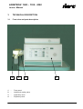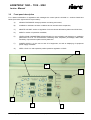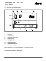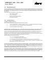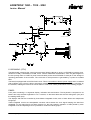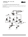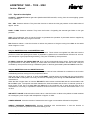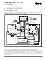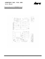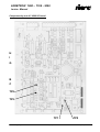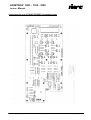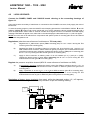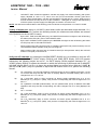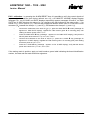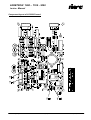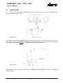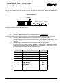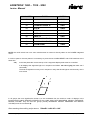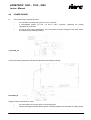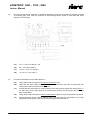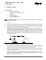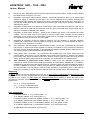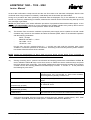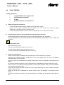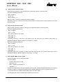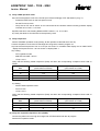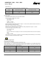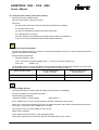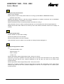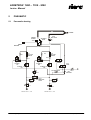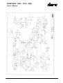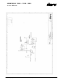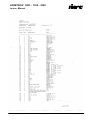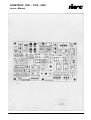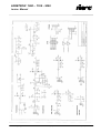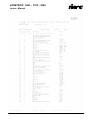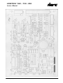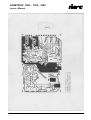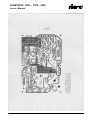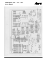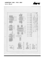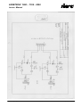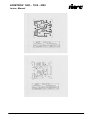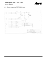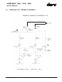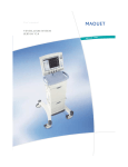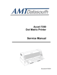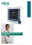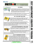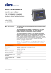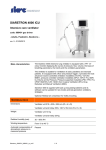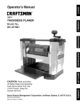
1
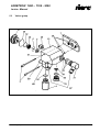
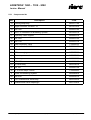
SIARETRON 1000 – 1100 - 3000
Service Manual
SIARETRON 1000
SIARETRON 1100
SIARETRON 3000
SERVICE MANUAL
SIARETRON_SE3_en
1 / (72 )
( rev.3) 30.06.2004
SIARETRON 1000 – 1100 - 3000
Service Manual
INDEX
1 USE OF SERVICE MANUAL ........................................................................................................................ 3
1.1
MANUAL USERS ....................................................................................................................................................... 3
1.2
CONSULTING NOTES................................................................................................................................................. 3
1.3
SAFETY NOTES................................................................................................................................................... 3
2 GENERAL MAINTENANCE PROCEDURES................................................................................................ 5
2.1
GENERALITY............................................................................................................................................................ 5
3 TECHNICAL DESCRIPTION......................................................................................................................... 6
3.1
FRONT VIEW AND PARTS DESCRIPTION ....................................................................................................................... 6
3.2
FRONT PANEL DESCRIPTION ...................................................................................................................................... 7
3.3
REAR VIEW AND PARTS DESCRIPTION ......................................................................................................................... 8
3.4
OPERATING PRINCIPLE ............................................................................................................................................. 9
3.4.1
3.5
Hardware features....................................................................................................................................... 9
GAS ADMINISTRATION AND PROPORTIONING PNEUMATIC SYSTEM ................................................................................ 12
3.5.1
Operation description ................................................................................................................................ 13
4 CALIBRATION AND TESTING.................................................................................................................... 15
4.1
LV200-MAIN/1 CPU BOARD ................................................................................................................................. 15
4.2
LV200 I/O BOARD .............................................................................................................................................. 21
4.3
PANEL BOARD .................................................................................................................................................. 25
4.4
POWER BOARD................................................................................................................................................. 28
4.5
PNEUMATIC CIRCUIT ....................................................................................................................................... 30
4.6
FINAL TESTING ................................................................................................................................................. 33
5 PNEUMATIC................................................................................................................................................ 41
5.1
PNEUMATIC DRAWING............................................................................................................................................. 41
5.2
PNEUMATIC COMPONENTS LIST................................................................................................................................ 42
5.3
VALVES GROUP ..................................................................................................................................................... 43
5.3.1
Components list......................................................................................................................................... 44
6 ELECTRONIC.............................................................................................................................................. 45
6.1
ELECTRIC DRAWINGS FOR TEST ATS.098 TOOLS.................................................................................................... 71
6.2
SIARETRON 1100 - PNEUMATIC DRAWING................................................................................... 72
Warning
SIARE is used throughout the description inside this manual as an abbreviation for
SIARE HOSPITAL SUPPLIES S.r.l.
Via Giulio Pastore, 18 - 40056 Crespellano (BO) - ITALIA
Tel.: 051/969802 / Fax: 051/969101
Manufacturer of the equipment described in the manual hereto
SIARETRON_SE3_en
2 / (72 )
( rev.3) 30.06.2004
SIARETRON 1000 – 1100 - 3000
Service Manual
1
USE OF SERVICE MANUAL
1.1
Manual users
This manual is addressed to SIARE qualified personnel or to technical qualified personnel formerly authorized
by SIARE.
The SIARE authorized technician has the instruments and suitable spare parts and he is instructed to operate
respecting product safety.
SIARE declines any responsibility arising from technical interventions effected on the equipment without its
formal authorization.
The correct and safe use of the equipment both for patient an operator requires the knowledge of
recommendations and instructions contained in the present manual and in the User’s Manual.
1.2
Consulting notes
The mark !
and operator.
reported next to and instruction individuates an important remark for the safety both of patient
The manual describes the equipment and the operating principle with the aid of electric and pneumatic
drawings.
The User’s Manual is part of this manual, the technician must have a copy of User’s Manual and must know its
content before effecting the operations described in the present manual.
1.3
SAFETY NOTES
WARNINGS !!
The equipment has been manufactured under the warranty and quality conditions of the product and its
components in order to assure the maximum reliability of the equipment and safety for the patient and operator.
Therefore, the safety is guaranteed only in case the technical interventions are effected in conformity to this
manual indications and those contained in the user’s manual which is unseparable par of the product
documentation currently used by the service.
Always in order to grant safety it is necessary to respect the maintenance schedule foreseen in the user’s
manual.
The maintenance and replacement of any part must be effected by personnel formerly authorized by SIARE
using the original SIARE spare parts or checked by the same.
SIARE is not civically or criminally liable in the following cases:
1)
Use in conditions and for reasons not stated or prescribed in service and user’s manuals.
2)
Lack or omission of scheduled maintenance as described in service and user’s manuals.
3)
Maintenance performed by personnel not formerly authorized by SIARE.
4)
Use of non original SIARE spare parts or not checked by the same.
5)
Connection with equipment that is not in compliance with Safety Norms in effect for intended use.
SIARETRON_SE3_en
3 / (72 )
( rev.3) 30.06.2004
SIARETRON 1000 – 1100 - 3000
Service Manual
!
Not connect the equipment to the patient by antistatic conductive hoses.
Since the use of antistatic hoses can cause burns when high frequency surgical equipment are used, their use
is not allowed in any application with this equipment.
For general safety of electro medical equipment, we underline the important aspect of interaction existing
between the equipment and the patient, the operator and environment.
For a correct and safe employ of the equipment it is absolutely necessary to follow the indications of the present
manual and user’s manual, observing the supplied indications.
Any operation on equipment presupposes the precise and correct knowledge of the present instructions.
The equipment must be submitted to an inspection and maintenance every 6 (six) months by SIARE qualified
technical personnel. All interventions carried out by qualified personnel are registered on a maintenance report.
Any repairing intervention must be carried out by SIARE qualified personnel or by qualified technical personnel
authorized by SIARE.
SIARE decline any responsibility for direct or indirect damages or prejudices to persons arising from not
authorized technical interventions or from an improper use of the same not in conformity to user’s and service
manual indications.
For repairing the equipment affected by malfunctioning, defect or failures, the dedicated personnel for use of the
equipment must contact SIARE or the local Service authorized to carry out the repairing or eliminate the
malfunctioning. It is necessary that at the moment of intervention request the model and serial number of the
involved equipment must be specified.
Use exclusively the suggested accessories.
It is allowed to use other accessories only in case of formal SIARE authorization, in conformity to safety norms
in force.
The equipment operation is only allowed in rooms equipped in accordance to the safety norms in force.
SIARETRON_SE3_en
4 / (72 )
( rev.3) 30.06.2004
SIARETRON 1000 – 1100 - 3000
Service Manual
2
GENERAL MAINTENANCE PROCEDURES
2.1
Generality
!
In order to grant both patient and operator safety the equipment must be inspected and checked as soon as
1000 hours operation are reached or in case of not intensive use of the equipment every 6 months at least.
Such inspections and checking’s require a perfect knowledge of involved equipment, so they must be carried
out exclusively by highly qualified personnel and specifically instructed and formerly authorized by SIARE.
It will be care of the Clinician or Anesthetist, to carry out the ordinary maintenance on the equipment as per
indications of the user’s manual.
The cleaning, disinfections, and parts replacement operations will have to be effected respecting the instructions
of the user’s manual in order to avoid damages to the components which could also compromise the patient and
operator safety.
The employed materials have been carefully selected during projecting phase after specific verifications, and
comparative tests.
Furthermore, the same materials are constantly tested during manufacturing cycle in order to obtain the
maximum reliability and safety for patient and operator.
Therefore, any part or circuit must be replaced exclusively with original spare parts supplied or checked by
SIARE.
SIARE assumes all law responsibility foreseen in case the used equipment is submitted to periodic maintenance
in accordance to the modalities indicated in the user’s manual and in this manual. As a proof that maintenance
has been carried out a Maintenance Report made and signed by SIARE authorized technician is necessary.
SIARETRON_SE3_en
5 / (72 )
( rev.3) 30.06.2004
SIARETRON 1000 – 1100 - 3000
Service Manual
3
TECHNICAL DESCRIPTION
3.1
Front view and parts description
1 - Front panel
2 - Ambient air safety valve
3 - Inspiratory valve
4 - Expiratory valve
4
3
2
1
-
Front panel
2
-
Ambient air safety valve
3
-
Inspiratory valve
4
-
Expiratory valve
SIARETRON_SE3_en
1
6 / (72 )
( rev.3) 30.06.2004
SIARETRON 1000 – 1100 - 3000
Service Manual
3.2
Front panel description
For a better individuation of regulations and messages the control panel is divided in 7 sections listed here
below (from left to right and from top to bottom):
A)
AIRWAY PRESSURE: airways pressure monitoring and control;
B)
ALARMS: or indicators of alarm conditions and of acoustic alarm suspension;
C)
MINUTE VOLUME: section of regulation of minute volume delivered to patient and CPAP flow;
D)
MODE or section of operative modalities;
E)
VENTILATION PARAMETERS REGULATIONS: for the regulation and displaying of ventilation
parameters such as: O2 Concentration, Breathing Rate, Inspiration percentage, SIMV Rate,
Sensitivity of spontaneous patient activity detection.
F)
POWER SUPPLY: for the turn-on and off of equipment, as well as displaying of equipment
power supply modalities.
G)
PEEP / CPAP: for end expiration positive pressure regulation or CPAP.
G
A
B
C
D
E
SIARETRON_SE3_en
F
7 / (72 )
( rev.3) 30.06.2004
SIARETRON 1000 – 1100 - 3000
Service Manual
3.3
Rear view and parts description
HOSPITAL SUPPLIES
Crespellano (BOLOGNA) ITALY
TEL. 051 - 969802 FAX 051 - 969366
Mod.
Volt
SERIE
A.
Fuse
Fuse
CLASSE 1 TIPO B CEI 62-5 DEL 1991
MADE IN ITALY
7
-
Main switch
8
-
Protection fuses
9
-
220V power supply outlet
10 -
RS 232 interface
11 -
Cooling fan wheel
13 -
Identification label
14 -
Air inlet connection
15 -
Oxygen inlet connection
18 -
12Vdc power supply inlet connector
If the fan wheel stops for a failure or an obstruction, an acoustic alarm sounds.
The same occurs in case of power failure.
SIARETRON_SE3_en
8 / (72 )
( rev.3) 30.06.2004
SIARETRON 1000 – 1100 - 3000
Service Manual
3.4
Operating principle
The lung ventilators of SIARETRON series are devices for assisted ventilation equipped with a microprocessor
control system composed of a 5 printed circuits kit; such a system controls the pneumatic circuit which delivers
the medical gas to the patient and permits to the operator the setting of operating parameters by a button panel
and a display.
The printed circuits composing the control system are:
3.4.1
•
Power supply (POWER)
•
cpu (LV200-MAIN/1)
•
panel and panel control (PANEL)
•
input/output (LV200I/O)
Hardware features
POWER (POWER SUPPLY)
Device power supply board. It controls three different power sources:
1.
12 Vdc (external battery: it needs a “presence contact”, or a staple closed between two clamps)
2.
12 Vac (secondary of a main powered transformer at 220V/50Hz)
3.
12 Vdc (rechargeable internal battery)
Here below listed in decreasing priority order; on the board two 2,5A fuses are present on the inlets of the two
batteries, while the main inlet is protected by fuses on 220 V power line at the level of the main switch block.
In case of main power supply the board provide to recharging internal battery in a maximum of 10 hours; such a
recharging can be effected also when the machine is off, provided that main switch (on the rear side) is on.
The start-up of the machine (which is made by pressing the ON/OFF button on the front panel) and the choice
of power supply source are made by dedicate relay present on the board.
The board generates the following tensions:
•
+ 5 V / 1 A for the logic part of the system,
•
+ 8 V / 1,5 A for displays and panel leds powering;
•
20 V not stabilized for the polarization of analog electronic presents on LV200I/O board;
•
12 ÷ 15 V not stabilized (depends on which source is used) for powering of pneumatic circuit
electro valves, fan wheel, buzzer and relays.
The turn-on/off mechanism is effected by the circuit indicated in figure 1; with the ON/OFF switch of the panel
the two clamps get in contact the two CN2 connector clamps, starting up the Q3 transistor whom excites the K3
relay. Hence, the Vcc tension is generated (through the 8301L stabilizer) whom supply the micro controller on
the CPU board, this generates by its side an high logic level (Vcc) on the line denominated AUTO_ON whom
maintains the K3 relay excited (and so all the device is powered).
The turn-off by ON/OFF switch is possible thanks to the Q5 transistor, through whom the micro controller knows
switch status, the software carries out the turn-off when it reads the pressed switch for more than one second,
generating a low logic level (0 V) on the AUTO_ON line and turning-off all peripheral devices (display and
electro valves). The machine remains, anyway, physically powered since the ON/OFF switch is released.
SIARETRON_SE3_en
9 / (72 )
( rev.3) 30.06.2004
SIARETRON 1000 – 1100 - 3000
Service Manual
COOLING FAN WHEEL
LV200-MAIN/1 (CPU)
The Main board containing the control microprocessor (Hitachi H8/532 at 16 bit), an EPROM of program (max.
dimension 64 KB), a data RAM of 32 KB, a GAL 16V8 for addresses decodification, some I/O gate mapped on
the bus (among them an UART for panel communication) and a serial E2PROM of 128 byte for the storage of
operating parameters of the machine. The clock rate of microprocessor is generated by a quartz at 19,6608
MHz.
The board is equipped with a WATCH DOG circuit. This is not sensible to electric power supply and it is realized
with an NE555; such a circuit is able to generate a resetting of microprocessor if it not periodically “refreshed” by
the software, retaking the machine in a know status in case of not correct performance of the working program.
PANEL
Front panel containing a 7 segments display, indication leds and buttons. The keyboard is composed of 20
buttons and 4 dip switches organized in a 5 x 5 mother; on the board there also are the writing latch (374) and
the reading buffer (244).
The displays and leds are controlled by three M5451 integrated circuits, each of them drives two multiplexate
led groups.
These integrated circuits are serie/parallel converter which shares the clock signal keeping the data lines
separated; on the board there are three trimmers for the light intensity regulation of leds piloted by each
integrated circuit and adjusting them it is possible to conform the three groups.
SIARETRON_SE3_en
10 / (72 )
( rev.3) 30.06.2004
SIARETRON 1000 – 1100 - 3000
Service Manual
PANEL (PANEL MANAGER)
The panel control board, contains an Hitachi H8/325 micro controller which effects the keyboard reading and
displays management.
It communicates with the main micro controller (H8/532 on the LV200-MAIN/1 board) through a serial port; it
forwards the acquired buttons and receives the data to be displayed using an internal protocol.
The board is equipped with WATCH DOG circuit not sensible to electric power supply realized with an NE555;
such a circuit is able to generate a microprocessor reset if it is not periodically “refreshed” by the software,
retaking the machine in a know status in case of not correct performance of working program.
The program, which is located in an EPROM inside the micro controller, performs a complete scanning of
keyboard approx. each 260 µs and manages the displays with a multiplexer frequency of approx. 47 Hz.
LV200I/O (INPUT/OUTPUT)
Input/output board managing the pneumatic circuit.
The printed circuit is divided in two sections, whom are kept separate as most as possible, an analog and a
digital one.
In the analog part there are stabilizers for the necessary electric power supplies (+10 V, -10 V) and all circuits
for input signals conditioning, namely the amplifiers, filters, protection devices.
The analog inlets are:
•
pressure signal (from transducer MPX10 mounted on board edge);
•
O2 concentration signal (from an external oxymetry sensor);
•
MINUTE VOLUME setting signal (from potentiometer on the panel);
•
measurement signals of O2 and AIR flows (from two external flow meters).
The mass of the analog section is physically kept separate from the mass of digital section; the only contact
point of these two masses is on the LV200-MAIN/1 board on the microprocessor pins.
The digital section of the board includes:
•
two digital inlets (contact cleaned by the two pressure switches);
•
an outlet for signaling buzzer
•
an ON/OFF electro valve outlet for medical gas commutation flow;
•
two outlets for flow by-pass;
•
two control outlets for proportional electro valves which regulate the flow of the two medical gas.
The proportional electro valves control is performed in PWM by two integrated circuits TL494, arranged on a
commutation frequency of approx. 30 KHz. The feedback of each of these integrated circuits is made on the
electric power of the relevant proportional electro valve; the set point (as electric power) is supplied by main
micro controller (H8/532 of LV200-MAIN/1 board) through an integrated low frequency signal PWM.
SIARETRON_SE3_en
11 / (72 )
( rev.3) 30.06.2004
SIARETRON 1000 – 1100 - 3000
Service Manual
3.5
Gas administration and proportioning pneumatic system
The gas administration and proportioning pneumatic system is represented in the following figure and
mechanical study.
The system has the function to administrate in a correct and safe way the breathing gas to the patient, under the
total control of electronic system.
PATIENT
OXIGEN
SENSOR
AIR SAFETY
VALVE
LPV2
EXP. VALVE
AIRWAY
PRESSURE
TRANSDUCER
R1
FS 1
O2 FLOW
SENSOR
R2.1
R1.1
EV PART. 1
O2
FS 2
AIR FLOW EV4
SENSOR
R2
EV PART. 2
AIR
EV PROP.
1
O2
EV 3
V.EXP.
EV PROP. 2 INSP.
AIR
FR 3 PEEP/CPAP
PR 3
FR3.1
FR 3
MAX PAW
CSV 1
GAS SELECTOR
VALVE
PSW 1
PSW 2
PR 1
PR 2
INLET AIR 3.5 bar +/- 0.75
INLET O2 3.5 bar +/- 0.75
SIARETRON_SE3_en
12 / (72 )
( rev.3) 30.06.2004
SIARETRON 1000 – 1100 - 3000
Service Manual
3.5.1
Operation description
O2 INLET – AIR INLET Medical gas inlets (Medical OXYGEN and AIR, coming from the central piping system
or from cylinders).
PR1 - PR2. Pressure reducers. They have the function to reduce the inlet gas pressure to the stable value of
approx. 2.6 bar.
PSW1 - PSW2. Pressure switches. They have the function of signaling the eventual gas failure or low gas
pressure.
CSV1. Circuit selecting valve. It has the function to guarantee the operation of pneumatic devices supplied by
PR3 reducer also with only one gas in the inlet.
PR3 Pressure reducer. It has the function to reduce the pressure of the gas coming from CSV1 to the stable
value of approx.1.5 bar.
Only for SIARETRON 1000 and SIARETRON 3000
EV PART 1 O2 - EV PART 2 AIR. 12 V Pilot electrovalve. These valves are supplied from PR3 and have the
function to control the opening and closure of pneumatic by-passes for the measurement of flows over 15 l/min.
(see description of gas proportioning assembly). They are controlled by microprocessor.
EV PROP 1 INSP O2 - EV PROP 2 INSP AIR. 6V 0-120 l/min proportional electro valves. These valves regulate
the gas delivered to the patient allowing to control both the O2-AIR concentration and the FLOW. They are
controlled by microprocessor through a feedback system on the flow guaranteed by PS1 and PS2 flow sensors
Only for SIARETRON 1000 and SIARETRON 3000
R1.1 - R1 - R2.1 - R2. Pneumatic resistances. They are made of holes calibrated in accordance to the function
of distributing the flow coming from the proportional valves.
When the flow is lower or equal to 15 l/min the EV PART 1 and 2 valves are excited and the communication
with R1 and R2 is interrupted. In this way the flow will completely pass through the PS1 and PS2 sensors for
measurement.
When the flow is higher than 15 l/min the EV PART 1 and 2 valves are disexcited and the communication with
R1 and R2 is open. The special connection between the holes’ diameters and the form of channels, permit to a
know portion of the flow to bypass PS1 and PS2 and to the remaining part to pass through them for the
measurement. In this way it is possible to measure the flow since from 0.1 to 99 l/min with sensors from 0.1 to
15 l/min.
AIR SAFETY VALVE. Unidirectional mechanic valve. It has the function to allow to the patient to breath ambient
air in emergency case. It opens with a depression of approx. 2 mBar.
OXIGEN SENSOR. It has the function of measure the real oxygen concentration delivered to the patient.
AIRWAY PRESSURE TRANSDUCER. Pressure transducer with semiconductor. It has the function to
continuously measure the pressure inside the breathing circuit.
SIARETRON_SE3_en
13 / (72 )
( rev.3) 30.06.2004
SIARETRON 1000 – 1100 - 3000
Service Manual
FR3 PEEP/CPAP. Flow regulator. It has the function to keep inflated the LPV2 expiratory valve, during the
expiration phase in CPAP modality, so that the patient CFR (residual functional capacity) will rise.
FR3 MAX PAW. Flow regulator. It has the function to keep inflated the LPV2 expiratory valve during the
inspiration phase, so that the circuit discharge will be closed and the lungs inflating will be possible. This
regulator is tared in combination with FR3.1 regulator, so that the expiratory valve will automatically open if the
airways pressure is higher than 80 mBar.
EV3 V. EXP. 12 V pilot electrovalve. It has the function to activate the LPV2 expiratory valve in accordance with
the inspiratory and expiratory cycle. It is microprocessor controlled.
EV4. DISCHARGE. 12V pilot electrovalve. It has the function to discharge in the environment the exceeding
inspiratory portion during PS and CPAP. It is microprocessor controlled.
FR3.1. Flow regulator. It has the function to regulate the discharge of LPV2 expiratory valve inflating system; it
works in combination with FR3 and FR3 MAX PAW.
FS1 O2 FLOW SENSOR, FS1 AIR FLOW SENSOR. Flow capacity transducers. They have the function to
measure the air and O2 flows delivered to the patient. Thanks to R1.1, R1, R2.1 and R2 it is possible the flow
measurement from 0.1 to 99 l/min with sensors from 0.1 to 15 l/min.
SIARETRON_SE3_en
14 / (72 )
( rev.3) 30.06.2004
SIARETRON 1000 – 1100 - 3000
Service Manual
4
CALIBRATION AND TESTING
4.1
LV200-MAIN/1 CPU board
Connect the POWER, PANEL and LV200I/O boards (already tested) and the board to be tested by the
appropriate cables kit; referring to the following connecting drawings:
LV200PW
cn-2
cn-1
220Vac
cn-7
cn-8
CVL-056
Transformer
(220Vac - 12 Vac)
CVL-053
CVL-058
P-10
P-3
CVL-072
cn-1
P-8
LV200_MAIN1
LV200I/O
CVL-052
cn-8
CVL-071
P-2
cn-3
P-5
P-4
cn-5
1
EV ON/OFF
CVL-054
JP1
LV100-P/1
P-3
LV100-ESP
JP1
POT
CVL-055
Connect the secondary of transformer to CN7 POWER connector; supply the primary of transformer.
To enter the testing program, press the ON/OFF switch keeping pressed the LOW AIRWAY PRESS. Í and HI
AIRWAY PRESS Í keys until hearing a short sound, hence release the above indicated switches and press
the ALARM RESET key within 5 seconds. Another short acoustic signal will occur, on the MINUTE VOLUME
display message TESTING will scroll once, after that on the same display will appear alternatively the
messages: I-O | ofG .
SIARETRON_SE3_en
15 / (72 )
( rev.3) 30.06.2004
SIARETRON 1000 – 1100 - 3000
Service Manual
Testing Performance Procedure
Acting on the PANEL board, while the alternated scripts: I-O | ofG (on DS13/14/15) appear, perform the
following checks (the referrals under brakes are relevant to the positions on the PANEL board):
•
By the AUT. TIME CYCLED (SW7) button the ON/OFF electrovalve must light ON and OFF
following the status of the LED (LD1) next to the (LED ON, LED OFF) button.
•
By the AUT. PRESS CYCLED (SW2) button the BUZZER must light ON and OFF following the
status of LED (LD2) next to the (LED ON, LED OFF) button.
•
With the main power supply the green ON LINE LED (LD12) must be light on.
•
With the external battery the yellow ON BATT LED (LD11) must be light on, simulate the
external battery with power supply regulated at 12 Vdc connected as follows:
Power
supply
•
Verify the connection of LOW BATT (LD10) alarm LED lowering the external power supply
whom simulates the battery. At an electric power between 10.5 and 11.2Vdc the alarm must
intervene.
•
By pressing the ON/OFF switch (SW1) the yellow SPONT. BREATH DETECTOR LED (LD5)
must light on.
•
Short-circuiting the CN6 connector feet of the LV200I/O board (Air inlet pressure switch) the red
LOW AIRWAY PRESS (APNEA).LED (LD7) must light off.
•
Short-circuiting the CN7 connector feet of LV200I/O board (O2 inlet pressure switch) the red
GAS SUPPLY.LED (LD9) must light off.
SIARETRON_SE3_en
16 / (72 )
( rev.3) 30.06.2004
SIARETRON 1000 – 1100 - 3000
Service Manual
A/D channels testing.
The testing phase of A/D channels starts by pressing the ALARM RESET (SW20) button. On O2 CONC
(DS9/10) and SIMV RATE (DS11/12) displays respectively appear messages: An and In , on RATE (DS3/4)
display appears message: Ch , on % INSP (DS5/6) display appears the channel on which the monitoring is
effected and on MINUTE VOLUME (DS13/14/15) display appears the analog/digital conversion value. With
the % INSP Í (SW14) and Î (SW17) switches the A/D channel can be adjusted from 0 to 5; perform the
following checks:
a)
Ch 0 (pressure): vary the inlet pressure of MPX10 sensor on the LV200I/O board from 0 to 80 cm of
H2O and verify that the A/D value on the MINUTE VOLUME (DS13/14/15) display changes from 20
± 1 to 100 ± 2.
b)
Ch 1 (oxymeter): apply to the CN12 connector an electric power variable from 0 to 75 mV between
the pin 4 (+) and the pin 1 (GND); verify that the corresponding A/D value changes from 0 to 225 ± 2.
c)
Ch 2 (MINUTE VOLUME potentiometer): rotate the potentiometer (POT) of MINUTE VOLUME
regulation and verify that the corresponding A/D value changes from 0 to 1023 (023 on display).
Ch 3 : not used.
d)
Ch 4 (AIR flowmeter): apply to the CN13 connector an electric power variable from 0 to 5 V between
the 4 (+) pin and the 2 (GND) pin; verify that the corresponding A/D value changes from 0 to
1000 ± 2.
e)
Ch 5 (O2 flowmeter): apply to the CN14 connector an electric power variable from 0 to 5 V between
the pin 4 (+) and the pin 2 (GND); verify that the corresponding A/D value changes from 0 to
1000 ± 2.
After the test verify the machine switch-off by pressing ON/OFF (SW1) button.
5)
If the testing result is positive, put on the board a green label indicating the identification number, the date
and tester technician signature.
SIARETRON_SE3_en
17 / (72 )
( rev.3) 30.06.2004
SIARETRON 1000 – 1100 - 3000
Service Manual
Component lay out of LV200-MAIN/1 board
SIARETRON_SE3_en
18 / (72 )
( rev.3) 30.06.2004
SIARETRON 1000 – 1100 - 3000
Service Manual
Component lay out of LV200 I/O board
H
I
G
B
C
TP2
TP3
TP1
SIARETRON_SE3_en
19 / (72 )
TP5
( rev.3) 30.06.2004
SIARETRON 1000 – 1100 - 3000
Service Manual
Component lay out of PANEL BOARD (component side):
SIARETRON_SE3_en
20 / (72 )
( rev.3) 30.06.2004
SIARETRON 1000 – 1100 - 3000
Service Manual
4.2
LV200 I/O BOARD
Connect the POWER, PANEL and LV200I/O boards referring to the connecting drawings of
figure 4.1.
Then verify that the secondary of transformer is connected to CN7 POWER connector; finally supply the main of
transformer.
To enter the testing program, press the ON/OFF switch keeping pressed the LOW AIRWAY PRESS. Í and HI
AIRWAY PRESS Í buttons until a short sounds will occur, hence release the above mentioned buttons and e
press ALARM RESET button within 5 seconds. Another short signal will sound, on MINUTE VOLUME display
message TESTIING will appear once, after that on the same display the alternated script: I-O | ofG will appear.
NOTE: from now and on all references to components and specific points of mounting plan have to be referred
to LV200I/O integrated circuit.
Regulations (take the mass reference of multimeter on TP1 test point):
A)
Regulate the +V_ANA electric power (TP5 of mounting plan) at +10 V ± 0,05 V turning the TR3
Trimmer (point A of mounting plan).
B)
Regulate the offset of acquisition channel of oxymetry cell; short-circuit the pin 1 and pin 4 of
AMP 4 leads CN12 connector; take at maximum gain by turning the TR1 multirevolution trimmer
(point B of mounting plan) clockwise; regulate the electric power of TP3 point of mounting plan
at 0 V ± 0,01 V by turning the TR2 trimmer (point C of mounting plan).
C)
Apply to CN12 connector an electric power of 75 mV between pin 4 (+) and pin 1 (GND);
regulate the electric power of point TP3 of mounting plan at 4,5 V ± 0,05 V turning the TR1
multirevolution trimmer (point B of mounting plan).
Regulate the pressure acquisition channel (MPX10: mass reference of multimeter on GND):
A)
At atmospheric pressure, regulate the electric power AD0 (TP2 of mounting plan) at +1V ± 10
mV by turning the TR1 multirevolution trimmer of offset on MPX10 hybrid circuit (point D of
mounting plan).
B)
Apply a pressure of 40 cm H2O ± 1 cm H2O to MPX10 sensor (point E of mounting plan);
regulate the electric power AD0 (TP2 of mounting plan) at +3V ± 50 mV turning the TR2
multirevolution trimmer of gain on MPX10 hybrid circuit (point F of mounting plan).
Regulation of battery alarm threshold: from panel, while the alternated scripts: I-O | ofG appears,
connect to the under testing board the battery simulator as per the following drawing:
Power
supply
SIARETRON_SE3_en
21 / (72 )
( rev.3) 30.06.2004
SIARETRON 1000 – 1100 - 3000
Service Manual
•
LOW BATT alarm threshold regulation: activate the supply from external battery (with power
supply adjusted at 10,9-11.0 V). hence turn the TR4 monorevolution trimmer (point G of
mounting plan) anticlockwise, until the red LOW BATT LED will light on. Hence, lightly turn the
trimmer clockwise and stop as soon as the LOW BATT. LED lights off. Verify that at decreasing
of electric power of power supply the LED lights on between 10.8 and 10.9 V.
NOTE: the references under brakes of the following point are relevant to the positions on LV100-P/1 board.
Testing of digital part: acting on LV100-P/1 panel board, while the alternated scripts alternate: I-O |
ofG appear (on DS13/14/15), perform the following checks (the references under brakes are relevant
to the positions on the LV100-P/1 board):
•
By the AUT. TIME CYCLED (SW7) key, the ON/OFF electovalve must light-on and off following
the status of the LED (LD1) next to LED ON/OFF switch.
•
By the AUT. PRESS CYCLED (SW2) key the BUZZER must light-on and off following the status
of LED (LD2) next to LED ON/ OFF switch.
•
Short-circuiting the CN6 connector feet of LV200I/O board (AIR inlet pressure switch) the red
LOW AIRWAY PRESS (APNEA LED (LD7) must light-off.
•
Short-circuiting CN7 connector feet of LV200I/O board (O2 inlet pressure switch) the red GAS
SUPPLY LED (LD9) must switch-off.
Verify the A/D channels: by pressing the ALARM RESET (SW20) key it is possible to verify the A/D
acquisition channels. On O2 CONC display (DS9/10) and SIMV RATE display (DS11/12) appear
respectively the following scripts: An and In , on RATE display (DS3/4) appears message: Ch , on
% INSP display (DS5/6) it’s shown the channel on which the monitoring is performed and on MINUTE
VOLUME display (DS13/14/15) it is shown the analog/digital conversion value. With the % INSP Í
(SW14) and Î (SW17) keys it is possible to adjust the A/D channel from 0 to 5; perform the following
checks:
a)
Ch 0 (pressure): vary the inlet pressure of MPX10 sensor on the LV200I/O board from 0 to 80
cm of H2O and verify that the A/D value on display MINUTE VOLUME display (DS13/14/15)
changes from 20 ± 1 to 100 ± 2.
b)
Ch 1 (oxymeter): apply to CN12 connector an electric supply adjustable from 0 to 75 mV
between pin 4 (+) and pin 1 (GND); verify that the corresponding A/D value changes from 0 to
225 ± 2.
c)
Ch 2 (MINUTE VOLUME potentiometer): turn the potentiometer (POT) of MINUTE VOLUME
regulation and verify that the corresponding A/D value changes from 0 to 1023 (displayed as
023).
d)
Ch 3 : not used.
e)
Ch 4 (AIR flowmeter): apply to CN13 connector an electric power adjustable from 0 to 5 V
between pin 4 (+) and pin 2 (GND); verify that the corresponding A/D value changes from 0 to
1000 ± 2.
f)
Ch 5 (O2 flowmeter): apply to CN14 connector an electric power adjustable from 0 to 5 V
between pin 4 (+) and pin 2 (GND); verify that the corresponding A/D value changes from 0 to
1000 ± 2.
SIARETRON_SE3_en
22 / (72 )
( rev.3) 30.06.2004
SIARETRON 1000 – 1100 - 3000
Service Manual
E.V.P. calibration: by pressing the ALARM RESET keys it is possible to verify the control signals of
proportional electrovalves (here below referred as e.v.p.). On MINUTE VOLUME displays appear
message E.Pr, on O2 CONC and RATE displays respectively appear messages O2 and Ai, on SIMV
RATE and % INSP displays the status of e.v.p. relevant to the gas indicate by the upper script ( -- for
closed e.v.p., On for open e.v.p.). Connect two proportional electro valves from 6V 1.2W to the CN10
connector (O2 between the clamps 1 (+) and 2 (-), AIR between the clamps 3 (+) and 4 (-)).
•
Connect the multimeter to the ends of O2e.v.p.; press the SIMV RATE Î button (message On
appears on SIMV RATE display); regulate the TR5 trimmer (point H of mounting plan) until
reading an electric power of 6V ± 0,1 V.
•
Press the SIMV RATE Í key (message – appears on the SIMV RATE display); verify that the
electric power at the ends of e.v.p. is of 1,5 V ± 0,2 V.
•
Connect the multimeter to the ends of AIR e.v.p.; press the % INSP Î key (message On
appears on % INSP display); regulate the TR6 trimmer (point I of mounting plan) until reading
an electric power of 6 V ± 0,1 V.
•
Press the % INSP Í key (message – appears on the % INSP display); verify that the electric
power at the ends of e.v.p. is of 1,5 V ± 0,2 V.
If the testing result is positive, apply on both boards a green label indicating the board identification
number, the date and the tester technician signature.
SIARETRON_SE3_en
23 / (72 )
( rev.3) 30.06.2004
SIARETRON 1000 – 1100 - 3000
Service Manual
Component layout of LV200I/O board:
SIARETRON_SE3_en
24 / (72 )
( rev.3) 30.06.2004
SIARETRON 1000 – 1100 - 3000
Service Manual
4.3
PANEL BOARD
1)
Connect the power supply (POWER board) to JP1 PANEL connector by the dedicate cable (as
indicated in the following drawing):
from F020_05
Connect the ATS.098 board to power supply (as indicated in the figure), verify that the switches of S1 are in
OFF position, connect the secondary of transformer to CN7 POWER connector, supply the main of transformer
and press the switch named “ON/OFF” on ATS.098 board for powering the device.
from F020_05
Verify that after some seconds, the scrolling script “ PAnnELLo Lu200 rEL. 4.00 “ appears on the MINUTE
VOLUME display.
SIARETRON_SE3_en
25 / (72 )
( rev.3) 30.06.2004
SIARETRON 1000 – 1100 - 3000
Service Manual
Press at the same time the two LOW AIRWAY PRESS. ÍandÎ switches; verify that all panel displays and leds
light-on, hence regulate their light intensity by mean of the trimmers present on the boards (as indicated here
below):
Light Iny Regulation
General
R7
Led bar+ Single Leds+ Display at
MAX AIR MIN VOL 7 segments
R6
R21
R12
Press any switch to return to scrolling script.
2)
Functional checks:
2.a)
Pressing the ALARM RESET key it is possible to effect the LED BAR check.
The leds are lighted on one by one in sequence: check that all leds light-on and that only one is on at a time.
2.b)
Pressing again the ALARM RESET key it is possible to verify the SINGLE LEDS
The leds are lighted-on one by one in sequence: check that al leds light-on and that only one is
on at a time.
2.c)
Pressing again the ALARM RESET keyit is possible to verify the KEYBOARD.
On MINUTE VOLUME display message “ tAStiErA “ scrolls, while on MAX/MEAN AIRWAY
PRESS display the SCAN CODE OF PRESSED SWITCH APPEARS (0 for any switch). Verify
the correspondence of the switches with the following table:
SCAN CODE
SIARETRON_SE3_en
KEY
SWITCH
1
CPAP
SW4
2
SPONT.SIMV
SW3
3
AUT.PRESS.CYCLED
SW2
4
AUT.TIME CYCLED
SW7
5
SIMV RATEÍ
SW6
6
SIMV RATEÎ
SW5
7
02 CONCÍ
SW10
8
02 CONCÎ
SW9
9
LOW AIRWAY PRESS.Í
SW8
26 / (72 )
( rev.3) 30.06.2004
SIARETRON 1000 – 1100 - 3000
Service Manual
SCAN CODE
TASTO
SWITCH
10
- LOW AIRWAY PRESS.
SW13
11
- HI AIRWAY PRESS. Í
SW12
12
HI AIRWAY PRESS. Î
SW11
13
RATEÍ
SW16
14
RATEÎ
SW15
15
%INSP. Í
SW14
16
%INSP. Î
SW17
17
TRIGGER SENSITIVITYÍ
SW18
18
TRIGGER SENSITIVITYÎ
SW19
19
ALARM RESET
SW20
NOTE: the on/off switch has not a scan code because its contact is directly taken on the POWER integrated
circuit.
In order to pass to the next phase it is necessary to press the two ALARM RESET and CPAP switches at the
same time.
2.d)
In this last phase the correct start-up of all 7 segments displays leds must be controlled.
In all displays the segments light on in sequence as follows: a-b-c-d-e-f-g-dp (the latter one if
connected).
The leds are lighted-on one by one in sequence: verify that all leds light-on and that only one is
on at a time
a
f
b
g
e
c
d
In all groups the more significative number is to be considered first; the switch-on order of displays is the
following:RATE-%INSP-TRIGGER SENSITIVITY-02 CONC.-SIMV RATE-MAX/MEAN AIRWAY PRESSUREMINUTE VOLUME. Only the last two groups (namely MAX/MEAN AIRWAY PRESSURE and MINUTE
VOLUME) have the connected dp.
After scanning the scrolling script returns: “PAnnEL Lu200 rEL. 4.00”.
SIARETRON_SE3_en
27 / (72 )
( rev.3) 30.06.2004
SIARETRON 1000 – 1100 - 3000
Service Manual
4.4
POWER BOARD
1)
Connect the power supplies to board:
•
the secondary of transformer (12Vac) in CN7 connector;
•
a rechargeable battery (12 Vdc, 3.2 Ah) in CN11 connector, respecting the polarity
serigraphically indicated;
•
the exit of power supply stabilized at 12V in the CN10 connector through the two ways switch,
as indicated in the following drawing:
from F020_03
Connect the testing equipment ATS.098 as indicated in the following drawing:
from F020_03
Supply the main of transformer; verify:
•
the commutation of K2 relay (point A of mounting plan);
•
that the rechargeable battery electric power increases (position the multimeter on battery poles).
SIARETRON_SE3_en
28 / (72 )
( rev.3) 30.06.2004
SIARETRON 1000 – 1100 - 3000
Service Manual
2)
3)
Press the switch named “ON/OFF” on ATS.098 equipment; verify the commutation of K3 relay (point B
of mounting plan), then verify the presence of the following electric power on CN8 (take the mass
reference on VR3 case):
2.a)
5.0 V ± 0.25 V on clamps 1,4,8;
2.b)
8V ± 0.2 V ON CLAMP 3:
2.c)
12.75 V ± 0.75 V on clamp 6;
2.d)
-21.5 V± 0.7 V on clamp 7.
Functional verifications of ATS.098 equipment:
3.a)
Verify that the red LED named “Fan Electric Power OK” is on;
3.b)
Verify that the green LED named “LINE” is on, then disconnect the main of transformer and
verify that the above mentioned LED lights-off;
3.c)
Activate the two ways switch on external battery and verify that the yellow LED named “EXT” is
on; also verify the K1 relay (point C of mounting plan) and the K2 relay (point A of mounting
plan) commutation;
3.d)
Verify that the red LED named “Switch-on/off pressure” lights-on any time the switch is pressed;
3.e)
Keep pressed the switch named “SWITCH-OFF” and verify that the commutation of K3 relay
(point B of mounting plan); wait until all ATS.098 equipment LEDS are off.
SIARETRON_SE3_en
29 / (72 )
( rev.3) 30.06.2004
SIARETRON 1000 – 1100 - 3000
Service Manual
4.5
PNEUMATIC CIRCUIT
Testing equipment:
!
Compressed Air Circuit
!
RT 200 Tester for flow measurement
!
Multimeter
!
0-6 bar Manometer
!
0-100 cm H2O Manometer
NOTE: this calibration phase must be effected after that the pneumatic part of ventilators
connected to its electric part.
1)
Preparation:
1.a)
Connect compressed air to gas inlets; connect the RT200 flow tester to the INSP outlet of patient circuit.
1.b)
Enter into testing program, by pressing the on/off switch and keeping pressed the LOW AIRWAY
PRESS. Í and HI AIRWAY PRESS Í keys until a short sound occurs, then release the above
indicated keys and press within 5 seconds the ALARM RESET key.
Another short acoustic signal occurs, on MINUTE VOLUME display message TESTING will scroll once,
after that on the same display the alternated scripts: I-O | ofG . will appear. Press twice again the
ALARM RESET key; on MINUTE VOLUME display message E.Pr. appears , on O2 CONC and RATE
displays the respective scripts O2 and Ai appears, on SIMV RATE and % INSP displays is indicated the
status of the proportional electrovalve relevant to the gas indicated by the above message (-- for closed
electrovalve, On for open electrovalve); such a status is selectable byÍ and Î keys relevant to SIMV
RATE and % INSP displays.
AIR
TR4
(BATTERY ALARM)
2)
Max EV-O2 electric power: Position the multimeter on the oxygen proportional electrovalve clamp; press
the SIMV RATE Î key to open the electrovalve, then regulate theTR5 trimmer of the LV200I/O board
so that to read a 6 V ± 0,1 V electric power. Block the TR5 trimmer with the lacquer.
3)
Max EV-O2 flow : Regulate the pressure before electrovalve with PR1 reducer so that to read on RT200
flow tester a flow of 100 l/min ± 0,1 l/min. Open and close twice the gas supply tap for delivery to
ventilator for stabilizing the reducer.
4)
Max EV-Air electric power : Close the electrovalve, by pressing the SIMV RATE Í key ; position the
multimeter on the air proportional electrovalve clamp; press the % INSP Î key to open the air
electrovalve, hence regulate the TR6 trimmer of LV200I/O board, so that to read a 6 V ± 0,1 V electric
power. Block the TR6 trimmer with lacquer.
SIARETRON_SE3_en
30 / (72 )
( rev.3) 30.06.2004
SIARETRON 1000 – 1100 - 3000
Service Manual
5)
Max EV-Air flow : Regulate the pressure before electrovalve with PR2 reducer so that to read on RT200
flow tester a flow of 100 l/min ± 0,1 l/min.
6)
Regulation of gas supply alarm pressure switches : Close both proportional valves. Act on external gas
reducer for supply to ventilator to have approx. 0.7-0.8 bar. Regulate the air pressure switches (see
enclosed pneumatic drawing) and oxygen one in such a way that under 0.5 bar are open, while over 0.9
bar they are closed (short circuit). Open and close twice the gas supply tap for delivery to ventilator for
stabilizing the reducer.
7)
Regulation of PEEP/CPAP main pressure: Connect the 0-6 bar manometer to the reducer outlet. Act on
reducer to have at its outlet 0.8 bar measured in still air. Open and closed twice the gas supply tap for
delivery to ventilator for stabilizing the reducer.
8)
Regulation of PEEP-CPAP pressure : Switch-off the ventilator and switch it on activating the CPAP
modality. Turn the PEEP knob of front panel to the max. PEEP value. Connect the low pressure
manometer (0-100 cmH2O) to the PAW outlet of patient circuit connected to a breathing bag. Act on a
flow regulator to have 20 cmH2O on the manometer.
9)
Regulation of expiration mushroom maximum pressure: Put the ventilator in automatic operation
modality with 15 bpm RATE. Close the PEEP-CPAP tap of front panel. Act on flow regulator to reach on
manometer a max. pressure of 75 cmH2O.
10)
Gain Verification: Put the ventilator in SPONT.SIMV modality, connect the compressed air to the PAW
inlet and act on external gas supply regulator for delivery to ventilator to have a pressure of 50cmH2O
and verify that the script 50 appears on the MAX/MEAN AIRWAY PRESS. display. Otherwise act on
TR2 trimmer (GAIN) of MPX10 pressure transducer board.
11)
Verify battery alarm at 10.5Vdc ± 0.2: disconnect the ventilator from main power supply and from
internal battery. Connect the 12 Vdc stabilized power supply and the tester in parallel to the battery
flying cables. Take slowly the electric power from 12Vdc to 10.3Vdc (read on tester) and verify at which
electric power the battery alarm intervenes. Eventually, act onTR4 trimmer of LV200I/O board.
12)
Auto calibration of proportional electro valves: to enter in the auto calibration procedure it is
necessary to switch-on the machine keeping pressed the Å LOW AIRWAY PRESS and Å HI AIRWAY
PRESS key at the same time; after a beep emission, release the keys and press the SIMV key within 5
seconds. It appears the AutoCAL scrolling script; press the Å SIMVR key within 10 seconds to enter in
the real procedure. The first phase is relevant ot the acquisition of remarkable points of flow sensors
feature; it is necessary to connect the flow tester (RT200) and manually search the required flows.
Displaying:
On RATE display is shown the operating gas (O2 or Air); on MAX AIRWAY PRESSURE and MINUTE VOLUME
displays is shown one value proportional to the proportional valve opening (displayed value / 2500 = duty cycle
of PWM of e.v.p. control); on SIMV RATE and TRIGGER SENSITIVITY displays is shown the result of A/D
conversion of ventilator internal flow transducer; on % INSP display is shown the flow value to search in the
following way:
15 -d Æ 15 l/min at direct flow
14 -r Æ 14 l/min at distributed flow
1 00 Æ 100 l/min at distributed flow
Keys managment:
-
HI AIRWAY PRESS Æ e.v.p. opening (step = 1)
Å HI AIRWAY PRESS e.v.p. closing (step = 1)
HI AIRWAY PRESS Æ and LOW AIRWAY PRESS Æ
Å HI AIRWAY PRESS and LOW AIRWAY PRESS Æ
HI AIRWAY PRESS Æ and Å LOW AIRWAY PRESS
Å HI AIRWAY PRESS and Å LOW AIRWAY PRESS
ALARM RESET data confirmation (e2prom script)
SIARETRON_SE3_en
31 / (72 )
e.v.p. opening (step = 10)
e.v.p. closing (step = 10)
min. duty (totally closed)
max. duty (totally open)
( rev.3) 30.06.2004
SIARETRON 1000 – 1100 - 3000
Service Manual
At each data confirmation a beep sounds and the new flow value to be searched is displayed; after the last
confirmed value a flag in e2prom is resetted (= valid tables) and the automatic procedure starts.
During such procedure the same previously described data are displayed; only if the calibration is correctly
carried out, previously resetted flag is restored, otherwise the machine cannot work and at any start-up an E16
error message is generated.
NOTE: the performance of the whole calibration procedure of proportional electrovalves takes approx. 3 hour
and it is not unterruptable; without its correct completion the ventilator signals at any start-up the Er16 error
message and it does not allow the normal operation. Switch-off the ventilator
13)
The duration Test: connect the ventilator to pneumatic power supply and to a patient circuit with a small
simulation bag. Switch-on the ventilator and after the autotest phase, take it to the automatic operation
with the following parameters:
RATE = 45 bpm
MINUTE VOLUME = 1,7 l/min
O2 CONC: = 21%
I:E RATIO = 33%
Put the max. and min. pressure limits at 5 - 7 cmH2O over and under the pressure peak. Leave
ventilator in continuous operation for at least 24 h. At finishing of this test verify that any alarm condition
is activated. After that switch-off the ventilator.
NOTE: Position the bag/simulator so that it does not move during all test phase. Every movement of
bag/simulator will cause a peak pressure variation, leading to the alarm condition.
14)
Zeroing of working hours : press the on/off switch and keeping pressed the LOW AIRWAY PRESS. Í
and HI AIRWAY PRESS Í keys until a short sound, so release the above mentioned keys and press
the CPAP button within 5 seconds . The “partial” worked hours and minutes are scrolled on the (namely
counted from the last zeroing) MINUTE VOLUME display in format: h. xxx Min. xx . In this procedure
the following keys are active:
HI AIRWAY PRESS Î
Displays the “historical” sum of the worked hours in the
following format: tot. h. xxx.xxx Min. xx . Such a sum considers
also the registered “partially” worked hours.
HI AIRWAY PRESS Í
Displays the “partially” worked hours in the previously described
format.
AUT. TIME CYCLED + RATE Î
Zeroing of “partially” worked hours after having added them to
the “historical” hours.
(simultaneously pushed)
CPAP + TRIGGER SENSITIVITY
(simultaneously pushed)
ALARM RESET
Î Zeroing of “historical” sum of worked hours.
Terminates the service procedure and makes the autotest start.
Verify that the worked hours are more than 24 and zeros the “partially” worked hours ( AUT. TIME
CYCLED + RATE Î buttons) and totals (CPAP. TRIGGER SENSITIVITY Îbuttons).
SIARETRON_SE3_en
32 / (72 )
( rev.3) 30.06.2004
SIARETRON 1000 – 1100 - 3000
Service Manual
4.6
FINAL TESTING
Testing equipment:
1)
!
couple 220Vac Power supply cable
!
ATS.033 patient simulator
!
RT 200
!
paediatric patient circuit of 120 cm
Effect the following connections:
2)
-
connect the electric power cable to ventilator and to main power supply;
-
connect to the couple compressed air and oxygen at 3,5 bar, connect the couple exit cables
respectively to the AIR and O2 lung ventilator inlets;
-
connect the paediatric patient circuit of 120 cm to ventilator and to ATS.033 patient simulator.
Verify the marks presence and check that the following labels are present:
2a) Identification label with data relevant to power supply predisposed for the “equipment”;
2b) label WARNING DO NOT USE IN PRESENCE OF INFLAMMABLE ANAESTHETIC GAS, in Italian and
in English.
!
3)
Verify fan wheel alarm.
Effect the following checks:
3a) with moving fan wheel the alarm must not occur;
3b) with disconnected fan wheel the alarm must occur;
3c) with mechanically blocked blades the alarm must occur.
4)
Autotest 1 and Autotest 2
Switch-on the ventilator. Immediately after the start-up the machine AUTO-TEST 1 begins.
Verify that the autotest is positive, namely that no error script appears (Exx or Axx) in the MINUTE
VOLUME display on the front panel.
Check that at the end of calibration the machine working hours number is displayed on the Minute Volume
display.
At the end of autotest the machine must go automatically in STANDBY (all operative modes leds are off).
Switch-off and on the ventilator keeping pressed the CPAP button (operative mode), so that immediately
the machine AUTO-TEST 2 starts.
Verify that the autotest is positive, namely that no error script appears (Exx or Axx) on MINUTE VOLUME
display on the front panel.
Check that at the end of calibration the machine working hours are displayed on the Minute Volume
display.
At the end of autotest the machine must go automatically in STANDBY (all the operative modes leds are
off).
SIARETRON_SE3_en
33 / (72 )
( rev.3) 30.06.2004
SIARETRON 1000 – 1100 - 3000
Service Manual
5)
Verify the IPPV operative mode
Select the IPPV operative mode by pressing the correponding button on the front panel.
5a) Set the following parameters:
- Rate = 50 B/min,
- %insp = 50
- Minute volume = 1 L
Disconnect the Y connector of patient circuit from simulator.
Completely close the Y connector and verify that the led bar of airway pressure arrives between 40 cm H2O
and 60 cm H2O;
6) Verify the PSV operative mode
Select the PSV operative modes by pressing the corresponding button on the front panel.
6a) Set the following parameters:
- Rate = 30 B/min
- Flow = 1 L/min
- High airway pressure = 40 cmH2O
- PSV TIME = 0
- TRIGGER = 0
Completely close the Y connector fo the patient circuit and verify that max. pressure value shown on
MAX/MEAN AIRWAY PRESS display is of 40 cmH2O ± 5 cmH2O.
6b) Set the following parameters:
- Rate = 30 B/min
- Flow = 1 L/min
- High airway pressure = 30 cmH2O
- PSV TIME = 0
- TRIGGER = 0
Completely close the Y connector of patient circuit and verify that the max. pressure value shown on the
MAX/MEAN AIRWAY PRESS. display is of 30 cmH2O ± 4 cmH2O.
7) Verify SPONT SIMV operative mode.
Connect the patient circuit to patient simulator.
7a) Set as follows:
-
SPONT SIMV operative mode
-
SIMV rate = 10
-
Rate = 15;MINUTE VOLUME = 6
-
TRIGGER = -3
7b) Wait for the generation of the first breathing act. Verify that, creating repeated depressions in the patient
simulator for approx. 6-8 seconds and pulling-out the bellow towards the bottom, a forced act will occur.
7c) Check that the max. settable value of SIMV rate is the value of Rate - 1.
7d) Verify that the number of setted acts are effectively the real one.
SIARETRON_SE3_en
34 / (72 )
( rev.3) 30.06.2004
SIARETRON 1000 – 1100 - 3000
Service Manual
8) Verify CPAP operative mode
8a) Connect the patient circuit to the P+inlet (Low Pressure Range) of RT 200 setted in prog. 12;
-
Rotate the PEEP knob on the front panel on max
-
Set the Flow at 30 L/min
-
Verify that on RT 200 is shown 20 cm H2O and that the ventilator max/min airway pressure display
indicates 20 cm H2O ± 1 cm H2O
8b) Effect the same check setting different PEEP values: 5, 10, 15 cm H2O.
8c) Verify the absence of noises due to the expiratory valve.
9) Verify frequences
Set the STANDBY operative mode (namely, all the operative modes led which are off).
Connect the patient circuit at the RT 200 High flow range inlet, setted in program 45.
9a) Check that all frequences from 5 to 70 bpm are shown on ventilator Rate display and on SIMV RATE
display the frequences from 1 to how shown on display Rate -1.
9b) Setting:
-
IPPV Operative mode
-
MINUTE VOLUME = 9L/min
-
%insp = 33 %
Verify that the following setted frequences (Rate) are within the corresponding acceptance limits read on
RT200.
Setted Ventilator
Rate
Lower acceptance limit
(read values on RT200)
Upper acceptance limit
(read values on RT200)
10
9
11
15
13.5
16.5
40
36
44
70
63
77
9c) Setting:
-
SPONT SIMV operative mode
-
Flow=9 L/min
-
%insp = 33 %
Verify that the following setted frequences (Rate) are within the corresponding acceptance limits read on
RT200.
Ventilator setted
Rate
Lower acceptance limit
(read values on RT200)
Upper acceptance limit
(read values on RT200)
5
4.5
5.5
10
9
11
20
18
22
10) Verify the inspiration/expiration ratio (%INSP)
Connect the patient circuit to high flow range inlet of RT200 setted with the 48 program.
Set the IPPV operative mode.
SIARETRON_SE3_en
35 / (72 )
( rev.3) 30.06.2004
SIARETRON 1000 – 1100 - 3000
Service Manual
Set the Rate = 6.
Set the %insp value of the table and effect the corresponding checks.
Setted Ventilator
%insp
Lower acceptance limit
(read values on RT200)
Upper acceptance limit
(read values on RT200)
25
1:2.7
1:3.3
33
1:1.8
2:2.2
50
1:0.9
1:1.1
11) Verify trigger
Connect the ventilator patient circuit to the patient simulator.
Check the trigger in negative effort; setting:
-
IPPV Operative mode
-
Rate = 5 bpm
-
Trigger = -3 cmH2O
-
MINUTE VOLUME = 9
Create a depression inside patient simulator of approx. -3 cmH2O, read on patient simulator manometer, by
pulling-off the bellow towards the bottom.
Verify that the ventilator generates a breathing act.
Repeat the test by setting the Trigger at -6 cmH2O and creating a depression of approx. -6 cmH2O.
11b) Check the trigger in positive effort: setting:
-
IPPV operative mode
-
Rate = 5 bpm
-
Act on the PEEP knob so to display 5 cm H2O on the Airway Pressure led bar at the end of expiratory
phase
-
Trigger = 5 cmH2O
Verify that at the end of expiration a breathing act starts immediately and automatically (it is not necessary
to wait for the setted 12 seconds with Rate = 5 bpm).
!
12) Verify the oxygen sensor
Connect the O2 to ventilator.
Take the machine in STANDBY (all operative modes leds are off).
Set the following O2 conc. values and verify that the value read on ventilator O2 conc. display, after that the
display stops flashing, is within the corresponding acceptance limits. Otherwise, verify that the ventilator emits
an acoustic alarm and the O2 conc. display is flashing.
Setted Ventlator O2 conc.
O2 conc.Lower acceptance limit
O2 conc Upper acceptance limit
2
20
22
40
36
44
60
54
66
99
90
99
SIARETRON_SE3_en
36 / (72 )
( rev.3) 30.06.2004
SIARETRON 1000 – 1100 - 3000
Service Manual
13) Verify the power failure (power failure alarm)
Set the IPPV+ASS. operative mode.
Disconnect the electric main power supply.
Verify that:
-
the ON LINE led switches-off and the ON-BAT led switches-on flashing
-
an acoustic alarm occurs
-
the alarm is resettable by pressing the alarm reset button
-
the ventilator keep on working
-
the Rate, Minute volume display and airways pressure led bar are always on
-
every 10 seconds are displayed also all other setted parameters.
!
14) Verify the bronchomanometer
Connect the patient circuit by a T connector to the patient simulator and to the P+ inlet of RT200 setted with
program 12 and with PEAK option.
Set the following parameters:
-
operative modality = IPPV
-
Flow = 10 L/min ( to check the PEEP at 20 ) – 5 L/min (to check the PEEP at 10 );
-
Rate = 20;
-%INSP = 33.
Act on PEEP knob so to set on Max/Mean airway pressure display the following pressures and verify that
the displayed values on RT200 are within the corresponding acceptance limits.
Setted ventilator PEEP
Lower acceptance limit
(read on RT200)
Upper acceptance limit
(read on RT200)
20
18
22
10
9
11
!
15) Verify leakage absence
15a) Tightness test from valves group to patient (Low pressure circuit leakage)
Connect the patient circuit to patient simulator.
Set the following parameters:
- Operative modality = SPONT SIMV;
- SIMV RATE = 1;
Act on PEEP knob so to set on airway pressure bar led the pressure of 20 cm H2O.
Verify that on the airway pressure bar led and on patient simulator manometer is displayed the pressure of
20 cmH2O ± 2 cmH2O for all the setted time (1 minute).
15b) Tightens Test of circuit (Leakage on main circuit)
Switch-off the ventilator.
Close upstream the manometer on the couple gas supply.
Verify that the pressure on manometer does not decrease under 3 bar in 30 sec.
SIARETRON_SE3_en
37 / (72 )
( rev.3) 30.06.2004
SIARETRON 1000 – 1100 - 3000
Service Manual
!
16) Verify the low pressure alarm
Switch-on the ventilator.
Set the pressure value for low pressure alarm at 10 cmH2O (LOW AIRWAY PRESSURE buttons).
-
operative mode: IPPV;
Regulate the Minute Volume so that the pressure displayed on simulator manometer and on Max/Mean
airway pressure display of ventilators of 10 cmH2O.
Reduce the Minute Volume so that the pressure decreases at 9 cmH2O.
Verify that within 30 sec an alarm sounds and that the Low Air Pressure led on the front panel lights on.
Repeat the test with alarm setted at 20 cmH2O (in this case reduce the Minute Volume so to display 18
cmH2O).
!
17) Verify the apnea alarm
Set the ventilator in IPPV+ASS. modality.
Connect the patient circuit to simulator.
Disconnect the patient circuit from simulator.
Verify that within 30 sec an alarm occur and the Low Airway Pressure led lights-on.
!
18) Verify the high pressure alarm
Set:
-
Operative Modality: IPPV.
-
Minute Volume = 1L.
-
Rate = 10 bpm.
-
% Insp = 50.
Set the high pressure alarm (High Airway Press. Limit) at 75 cmH2O.
Close the Y connector of patient circuit and verify that an acoustic and visual alarm occur (High Airway
Pressure led) and that the max. pressure displayed on led bar does not arrive at 80 cmH2O (max
mechanical limit).
Set the high pressure alarm (High Airway Press. Limit) a 40 cmH2O.
Close the Y connector of patient circuit and verify that an acoustic and visual alarm occurs (High Airway
Pressure led) and that the max. pressure displayed on led bar is not higher than 45 cmH2O (max.
mechanical limit).
SIARETRON_SE3_en
38 / (72 )
( rev.3) 30.06.2004
SIARETRON 1000 – 1100 - 3000
Service Manual
19) Verify the supply gas alarm
Set:
-
IPPV operative mode.
-
%insp. = 50.
Connect the patient circuit to simulator.
Close AIR supply on the couple.
Verify that an alarm sounds, that the Gas Supply led lights-on and that the A04 script is flashing on Minute
Volume display.
Restore the AIR supply.
Close the O2 supply on the couple.
Verify that an alarm sounds, that the Gas Supply led lights-on and that the A03 script is flashing on Minute
Volume display.
Restore the O2. supply.
20) PEEP control
Set:
-
IPPV operative mode.
Connect the patient circuit to simulator.
Rotate the PEEP regulator, until 10 cmH2O is shown on Max/Mean Airway Pressure display.
Verify that the pressure on simulator manometer is of 10 cmH2O ± 1 cmH2O.
Rotate the PEEP regulator to the max. value and verify that on the Max/Mean Airway Pressure display is
shown the 20 cmH2O value and that the pressure on simulator manometer is of 20 cmH2O ± 2 cmH2O.
21) Verify the ventilator functionality
Set:
- %INSP = 33%.
Select the IPPV+ASS operative mode by pressing the corresponding button on the front panel.
Connect the patient circuit to the Low flow range inlet of RESPICAL which is setted in “VOLUME” modality and
option “La”.
Set the following MINUTE VOLUME values and for each of them the corresponding RATE value as indicated in
the table; verify that the TIDAL VOLUME values displayed on RESPICAL are within the corresponding
acceptance limits (see table).
NOTE: Setting the Minute Volume at 15 and 25 it is necessary to pass to the HIGH FLOW inlet on the
RESPICAL always in “VOLUME” modality and option “La”.
SIARETRON_SE3_en
39 / (72 )
( rev.3) 30.06.2004
SIARETRON 1000 – 1100 - 3000
Service Manual
MINUTE VOLUME IMP.
(LITERS)
RATE IMP.
(BPM)
MIN ACCEPTANCE
LIMIT(LITERS)
MAX ACCETTANCE
LIMIT (LITERS)
LOW FLOW
1
2.5
4
3
5
8
6
35
0.025
0.031
50
0.018
0.022
70
0.012
0.015
35
0.064
0.078
50
0.045
0.055
70
0.032
0.039
35
0.10
0.12
50
0.072
0.088
70
0.051
0.062
20
0.135
0.165
35
0.077
0.094
50
0.054
0.066
20
0.225
0.275
35
0.128
0.157
50
0.09
0.11
20
0.36
0.44
35
0.20
0.25
50
0.144
0.176
12
0.45
0.55
20
0.27
0.33
30
0.18
0.22
12
1.125
1.375
20
0.675
0.825
30
0.45
0.55
12
1.875
2.291
20
1.125
1.375
30
0.75
0.91
HIGH FLOW
15
25
SIARETRON_SE3_en
40 / (72 )
( rev.3) 30.06.2004
SIARETRON 1000 – 1100 - 3000
Service Manual
5
PNEUMATIC
5.1
Pneumatic drawing
PATIENT
OXIGEN
SENSOR
AIR SAFETY
VALVE
LPV2
EXP. VALVE
AIRWAY
PRESSURE
R1
FS 1
O2 FLOW
SENSOR
R2.1
R1.1
EV PART. 1
O2
FS 2
AIR FLOW
SENSOR
R2
EV PART. 2
AIR
EV PROP. 1 INSP.
O2
EV 3
V.EXP.
EV PROP. 2 INSP.
AIR
FR 3 PEEP/CPAP
PR 3
EV4
CSV 1
GAS SELECTOR
VALVE
PSW 1
PSW 2
PR 1
INLET O2 3.5 bar +/- 0.75
SIARETRON_SE3_en
FR3.1
FR 3
MAX PAW
PR 2
INLET AIR 3.5 bar +/- 0.75
41 / (72 )
( rev.3) 30.06.2004
SIARETRON 1000 – 1100 - 3000
Service Manual
5.2
Pneumatic components list
Q.ty
Reference
Description
Code
1
2
PR1, PR2
EAR 2000 pressure regulator
P20000049
2
2
PSW1, PSW2
Switch pressure 0-2Bar NA 1/8 VITON diaphragm
P30000009
3
1
CSV1
Circuit selector valve G 1/8
P16000049
4
1
PR3
AR 1000 M5 pressure regulator
P20000039
5
2
EV PART1 O2, EV PART2 AIR
Electrovalve 3/2 N.C. 12 Vdc
P11000019
6
2
EV PROP 1 INSP O2, EV PROP Proportional Electrovalve 6V DC 2W 2 Bar P11000129
2 INSP AIR
120l/min
7
4
R1.1, R1, R2.1, R2
Separator Body
M52317009
8
1
AIR SAFETY VALVE
Green silicon unidirectional valve
P16000009
9
1
OXIGEN SENSOR
O2 cell
E75000004
10
1
AIRWAY
TRASDUCER
11
1
FR3 PEEP/CPAP
Multiround flow regulator DMRL 30/8
P24000019
12
1
FR3 MAX PAW
RG 4/8 RE connector
P24000049
13
2
EV3 V. EXP,EV4
3/2 N.C. 12 Vdc electrovalve
P11000019
14
1
FR3.1
RG 4/8 RU Connector
P24000069
15
2
FS1 O2 FLOW SENSOR, FS2 O2/air capacity trasducer 0-15l/min AWM5103VN
AIR FLOW SENSOR
SIARETRON_SE3_en
PRESSURE Deferred Press. trasducer MPX-10DP not comp.
42 / (72 )
E72000000
E73100000
( rev.3) 30.06.2004
SIARETRON 1000 – 1100 - 3000
Service Manual
5.3
Valves group
SIARETRON_SE3_en
43 / (72 )
( rev.3) 30.06.2004
SIARETRON 1000 – 1100 - 3000
Service Manual
5.3.1
Components list
Ref.
Description
Code
13
Valves group body
M52317709
31
Angle connector for M22 F15
M57007509
33
OR 2100
M10002100
37
M22 F15 connector for Breathing System
M57005519
27
Expiratory valve support
M58482319
30
OR 3150
M10003150
32
OR 2118
M10002118
29
Black expiratory valve
P16000019
41
Mushrooms bush H18
M50981109
36
O2 cell
E75000004
39
F22 scavenging connector
M57007909
40
Water trap connector
M57007809
4
Water trap
M20280009
34
OR 3100
M10003100
23
Air valve body
M52314619
26
OR 128
M10000128
35
N° 2 Green inspir. valves
P16000009
3
Screw for Breathing System
M59380909
28
OR 2010
M10002010
5
EXP unidirectional valve body
M52318109
6
Unidirectional valve diaphragm
M55110409
SIARETRON_SE3_en
44 / (72 )
( rev.3) 30.06.2004
SIARETRON 1000 – 1100 - 3000
Service Manual
6
ELECTRONIC
SIARETRON_SE3_en
45 / (72 )
( rev.3) 30.06.2004
SIARETRON 1000 – 1100 - 3000
Service Manual
SIARETRON_SE3_en
46 / (72 )
( rev.3) 30.06.2004
SIARETRON 1000 – 1100 - 3000
Service Manual
SIARETRON_SE3_en
47 / (72 )
( rev.3) 30.06.2004
SIARETRON 1000 – 1100 - 3000
Service Manual
SIARETRON_SE3_en
48 / (72 )
( rev.3) 30.06.2004
SIARETRON 1000 – 1100 - 3000
Service Manual
SIARETRON_SE3_en
49 / (72 )
( rev.3) 30.06.2004
SIARETRON 1000 – 1100 - 3000
Service Manual
SIARETRON_SE3_en
50 / (72 )
( rev.3) 30.06.2004
SIARETRON 1000 – 1100 - 3000
Service Manual
SIARETRON_SE3_en
51 / (72 )
( rev.3) 30.06.2004
SIARETRON 1000 – 1100 - 3000
Service Manual
SIARETRON_SE3_en
52 / (72 )
( rev.3) 30.06.2004
SIARETRON 1000 – 1100 - 3000
Service Manual
SIARETRON_SE3_en
53 / (72 )
( rev.3) 30.06.2004
SIARETRON 1000 – 1100 - 3000
Service Manual
SIARETRON_SE3_en
54 / (72 )
( rev.3) 30.06.2004
SIARETRON 1000 – 1100 - 3000
Service Manual
SIARETRON_SE3_en
55 / (72 )
( rev.3) 30.06.2004
SIARETRON 1000 – 1100 - 3000
Service Manual
SIARETRON_SE3_en
56 / (72 )
( rev.3) 30.06.2004
SIARETRON 1000 – 1100 - 3000
Service Manual
SIARETRON_SE3_en
57 / (72 )
( rev.3) 30.06.2004
SIARETRON 1000 – 1100 - 3000
Service Manual
SIARETRON_SE3_en
58 / (72 )
( rev.3) 30.06.2004
SIARETRON 1000 – 1100 - 3000
Service Manual
SIARETRON_SE3_en
59 / (72 )
( rev.3) 30.06.2004
SIARETRON 1000 – 1100 - 3000
Service Manual
SIARETRON_SE3_en
60 / (72 )
( rev.3) 30.06.2004
SIARETRON 1000 – 1100 - 3000
Service Manual
SIARETRON_SE3_en
61 / (72 )
( rev.3) 30.06.2004
SIARETRON 1000 – 1100 - 3000
Service Manual
SIARETRON_SE3_en
62 / (72 )
( rev.3) 30.06.2004
SIARETRON 1000 – 1100 - 3000
Service Manual
SIARETRON_SE3_en
63 / (72 )
( rev.3) 30.06.2004
SIARETRON 1000 – 1100 - 3000
Service Manual
SIARETRON_SE3_en
64 / (72 )
( rev.3) 30.06.2004
SIARETRON 1000 – 1100 - 3000
Service Manual
SIARETRON_SE3_en
65 / (72 )
( rev.3) 30.06.2004
SIARETRON 1000 – 1100 - 3000
Service Manual
SIARETRON_SE3_en
66 / (72 )
( rev.3) 30.06.2004
SIARETRON 1000 – 1100 - 3000
Service Manual
SIARETRON_SE3_en
67 / (72 )
( rev.3) 30.06.2004
SIARETRON 1000 – 1100 - 3000
Service Manual
SIARETRON_SE3_en
68 / (72 )
( rev.3) 30.06.2004
SIARETRON 1000 – 1100 - 3000
Service Manual
SIARETRON_SE3_en
69 / (72 )
( rev.3) 30.06.2004
SIARETRON 1000 – 1100 - 3000
Service Manual
SIARETRON_SE3_en
70 / (72 )
( rev.3) 30.06.2004
SIARETRON 1000 – 1100 - 3000
Service Manual
6.1
Electric drawings for TEST ATS.098 tools
SIARETRON_SE3_en
71 / (72 )
( rev.3) 30.06.2004
SIARETRON 1000 – 1100 - 3000
Service Manual
6.2
SIARETRON 1100 - PNEUMATIC DRAWINGS
SIARETRON_SE3_en
72 / (72 )
( rev.3) 30.06.2004