1
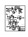
MC77 Limiting Amplifier
Effective with Serial Number 450
Operation and Service Manual
Table of Contents
1
2
3
4
5
6
7
8
9
10
11
12
Description
General Definitions
Specifications - Electrical
Specifications – General
Front Panel Controls
Back Panel Connections
Unpacking and Installation
Operating Instructions
Maintenance
Cleaning
Repairs & Warranty
News
13 Schematics
1. DESCRIPTION
The MC77 replaces the MC76 re-engineered 1176 type FET Limiter
After selling hundreds of the original MC76 units we incorporated new features based on
user feedback.
The MC77 is a gain limiting amplifier. Units of this type have been used for many years to
provide precise and automatic control of peak signal levels in recording studios, disc
mastering facilities, broadcast stations and sound reinforcement applications.
Gain reduction in the MC77 is accomplished using a Field Effect Transistor (FET) as a voltage
controlled variable resistor shunt. The FET is the first active component in the signal chain.
Large amounts of limiting can occur without large increases in distortion. There are four
compression ratios that can be used to best complement the program material and the
specific application.
Attack Time is continuously adjustable from less than 20microseconds to 800microseconds.
The fast attack time response is independent of peak frequency content or duration. Over
the audio band the full limiting action will stabilize in under a half cycle. Release time is
continuously variable from 50msec to 1.1sec. Release time is defined as the time it takes for
the gain to recover to within 63% of the normal non-limiting gain.
Provisions have been made for the interconnection of two MC77 limiters for stereo
operation.
2. GENERAL DEFINITIONS
Compressors and Limiters are used in many applications. A technical application for these
devices is when the dynamic range of program material is too large to be processed by
succeeding equipment, when the peak-to-peak amplitude is too large for the headroom of
the following equipment. Compressors and Limiters are used to reduce the dynamic range of
the program material so it "fits" through the equipment and systems that follow. Good
examples are broadcast transmitters and public address systems. A non-technical
application is as a production or creative tool. Any device that changes dynamic range will
cause some subjective change in the sound of the program material. Reducing the dynamic
range of an individual track in a multi-track recording and making it more consistent
makes it easier to control in the mixdown process. Its applications as a production tool are
limitless.
The two different terms (Compressors and Limiters) generally refer to the degree to which
the dynamic range is reduced. The relationship of input level change to output level
change is called the Compression Ratio. If, for example, an increase of 8 dB input signal
level should cause the output to increase by 2 dB, this would represent a 4:1 compression
ratio.
Amplifiers with compression ratios of up to 8:1 are often considered to be Compressors,
while those with ratios higher than 8:1 are called Limiters. The MC77 can function as a
compressor or a limiter since it has compression ratios from 4:1 to 20:1.
Signals at levels below the threshold will not be affected by the compression/limiting
action. Any change in input level below threshold will result in a corresponding and equal
change in output level while increases in input levels above the threshold will cause a
controlled decrease in amplifier gain resulting in a reduced increase in the output level in
proportion to the compression ratio. The MC77 Input Level control adjusts the amount of
signal to be processed above the threshold, and hence the degree of compression, or
limiting.
3. SPECIFICATIONS - ELECTRICAL
Note: the dB voltage level measurements listed here are referenced to
0.775 Volts RMS. We have seen dB measurements referenced to 0.775 Volts RMS labeled
interchangeably as dBu or dBv (note the little "v") while dBV (a big "V") uses 1 volt as a zero
reference... and to make things worse people still use the dBm scale to discuss voltage levels
across what they are measuring.... A dBm level is a measurement of power that references to
1mW dissipated into a given load and is almost always measured indirectly as a voltage
developed across a known load of 600 ohms. If someone tells us they are measuring +4dBm at
the input terminals of a device with a 10K ohm input impedance what are we to think? We
prefer the dBu scale because we are measuring voltages. Oftentimes, we are not measuring
across a 600 ohm "line" AND later when we read these specifications over the phone we
don't have to keep saying "dB little v"
Input: Constant Impedance Input Attenuator
Transformer Balanced and Floating
Input Impedance: 600 ohms at all input gain settings
Maximum Input Level: +30dBu with limiting active and input cranked up full
(Prolonged exposure to signal levels in excess of +30dBu may burn up the input attenuator)
Maximum Gain: 45dB ±1dB (with limit action switched off)
Frequency Response: 15Hz to 80KHz ±1dB typical
Output: Floating Transformer Balanced
Output Load: 150 ohms or higher
Load Dependence: The Output Level as measured while driving into a bridging load will
drop by no more than 1/2 dB when a load of 600 ohms is added there will be a loss in
headroom
Maximum Output Level: +24 dBm into 600 ohm load (12-1/4 volts RMS)
+30 dBu into bridging load (24-1/2 volts RMS)
SPECIFICATIONS - ELECTRICAL - continued
Distortion: Less than 0.5% THD+noise 22Hz-22KHz with limiting activeRelease time set to
1.1sec (fast release times will increase distortion at low frequencies) - NOTE: The VU meter
is now buffered from the audio and adds no appreciable distortion.
S/N Ratio: >81dB at threshold of limiting 22Hz - 22KHz unweighted
Attack Time: Less than 20µsec for full limiting action
adjustable to 800µsec with front panel control
Release Time: Minimum 50msec adjustable to 1.1sec maximum (for 63% recovery) with
front panel control
Threshold and Ratio: With the input control fully clockwise and the output gain control
set 10dB below maximum (at about 6 on the dial)
The overall gain (before limiting) should be 35dB (±1dB)
The threshold of limiting is defined here as 1dB of limiting
at 20:1 the threshold of limiting will occur with an input of -24dBu (±2dB) and yield an
output level of +10dBu
at 12:1 the threshold of limiting will occur with an input of -25dBu (±2dB) and yield an
output level of +9dBu
at 8:1 the threshold of limiting will occur with an input of -26dBu (±2dB) and yield an
output level of +8dBu
at 4:1 the threshold of limiting will occur with an input of -30dBu (±2dB) and yield an
output level of +7dBu
Note: lower ratios make the limiting action kick in sooner
SPECIFICATIONS - ELECTRICAL - continued
Power Requirements: 100-125 Volts AC or 200-250 Volts AC selectable
At 115 Volts the current draw is 1/2 mA (typical)
and the unit should be fused for 1/8 Amps
At 230 Volts the current draw is 1/4 mA (typical)
and the unit should be fused for 1/16 Amps
Line Frequency can be 50-60Hz
Temperature: The MC77 can operate safely over a temperature range of
0°C to +50°C
The MC77 can be stored over a temperature range of
-20°C to +60°C
4. SPECIFICATIONS - GENERAL
Dimensions: 2U 19" rack mounting enclosure (19" wide 3-1/2" high)
Depth behind front panel is 8" (not including connectors)
Finish: Front Panel is 1/8" thick aluminium purple anodized
with some variation in color - this can be viewed as a feature and lends a certain
individuality to each unit - Case finish is black powder coat. Legends are silk screened in
white.
Weight: 12 pounds – loose, 15 pounds – shipping weight.
5. DESCRIPTION OF FRONT PANEL CONTROLS
Input Level Control: Continuously adjustable rotary attenuator
Output Level Control: Continuously adjustable rotary potentiometer
Attack Time: Continuously adjustable rotary potentiometer
Ranges from the slowest attack time of 800 microseconds to the
fastest attack time of 20microseconds at the full clockwise rotation
Limiting In/Out: The Attack Time control has a switch position at its full
counter-clockwise rotation. This turns limiting action off
Release Time: Continuously adjustable rotary potentiometer
Ranges from the slowest release time of 1.1sec to the
fastest release time of 50msec at the full clockwise rotation
Insert: Engage for Insert/Key input mode. Side Chain Insert Loop Switch places a
differentially balanced send and return into the normal connection from the top of the
output pot to the side chain detector and gain control circuitry. This loop allows EQ, filters
and other external processors to be used to modify how the limiter responds i.e. as a vocal
stressor or with a low cut filter to limit bass and improve its definition. This insert is always
sending, return is bypassed until activated.
Link: Engage for stereo mode. New Stereo Link Circuit sums the audio feeding the control
circuitry of a pair of MC77 limiters instead of simply joining the FET busses. This eliminates
the need for alignment and the additive effect of attack and release times. Linked Stereo
limiting is now plug and play and the limiting action is now just as fast as in an unlinked
monaural MC76 or MC77.
Compression Ratio: Four Position Interlocked Push-button Switch allows selection of 4:1,
8:1, 12:1 and 20:1 compression ratios. Some users enjoy pushing more than one of these
buttons at once.
Meter Function: The VU meter is switchable between I/O level and Gain Reduction. Top
switch In position is for monitoring Gain Reduction, Out for monitoring I/O level. Second
switch In for Input level, Out for Output Level, Both referenced at +4dBu.
*Note Input level is monitored across the 600 Ohm input. You may notice a level drop
depending on source. This is normal loading and not a metering error
Bypass: The third switch is for system bypass, this connects the input directly to the
output so the user can quick A/B limiter in vs limiter out. Unit defaults to bypass when the
powered off.
Power Switch: The bottom switch is marked ON.
Gain Reduction "0" Adjust: Screwdriver accessible adjustment via small hole in front
panel between input and output level controls
6. BACK PANEL CONNECTIONS
XLR Pin Assignments:
PIN 1 = Chassis, Earth, Ground
PIN 2 = Signal "Hot", Positive, ø+
PIN 3 = Signal "Cold", Negative, ø-
Wiring systems vary from facility to facility. PIN 1 may or may not be used to terminate a
shield or drain wire. In general this pin and the shield or drain wires connected to it are
not to be used to “Ground” or “Earth” the unit. Shields and Drain Wires should NOT carry
current and are generally connected at only one end of any given wire. For your
convenience and to assure that the chassis can be easily grounded (earthed) there is a
Chassis Ground Lug on the back of the unit and the center pin of the IEC power inlet is
connected to the chassis as well.
PINS 2&3 of the input and output XLR connectors must be connected to get signal in and out
of the unit. Since the inputs and outputs are transformer balanced there is no problem
unbalancing either the input, the output or both. Because the input attenuator ahead of the
input transformer takes PIN 3 of the input XLR to signal common is the preferred way to
unbalance the input. To maintain consistent phase from input to output connection of PIN 3
to audio common is the preferred way to unbalance the output unless you WANT to flip the
phase.
Input & Output XLR: Standard connections - Transformer isolating.
Insert Send & Return XLR: a differentially balanced send and return into the normal
connection from the top of the output pot to the side chain detector and gain control
circuitry. This loop allows EQ, filters and other external processors to be used to modify how
the limiter responds i.e. as a vocal stressor or with a low cut filter to limit bass and improve
its definition. This insert is always sending return is bypassed until activated.
Stereo Interconnection: Two 1/4" Jacks marked Link, Input and Output are used to
connect two units together for stereo mode utilizing the link control on the front panel.
Using two 1/4” TS or TRS cables connect the Out jack on each unit to the In Jack on the
other unit.
IEC Power Inlet: Accepts standard IEC type power cable and includes:
Fuse Holder - see back panel markings for fuse rating
Audio & Chassis Ground: Audio ground is connected to the audio circuit, Chassis ground
is connected directly to the steel case and the IEC ground. These are shipped from the
factory linked, leave these linked unless you have a reason to separated your audio and
chassis grounds. If you do separate them leave the link on one of the lugs, otherwise you
will lose it.
7. UNPACKING AND INSTALLATION
Your MC77 was packed with care at the factory. The packaging was designed to protect the
unit from rough handling. However, once the unit leaves us, it may pass through the hands
of those who have no idea what is in the box, may not be happy with their job, or may like
to throw things. Despite the heavy duty carton and foam blocks the unit was packed with,
we recommend you inspect the box and its contents immediately for any sign of damage that
may have occurred in transit. If there is damage, you should save all the packing materials
and contact your vendor immediately. We recommend you keep the packing materials.
Murphy’s law states that once you throw away the box the likelihood you will need it back
will increase in proportion to the square of the distance from your service center
multiplied by the cost of replacement packing materials.
The carton we ship out contains:
*One MC77 Limiting Amplifier
*This Manual
*One six foot (two meters) IEC Cable
*Warranty Card
8. OPERATING INSTRUCTIONS
Start with all controls at mid–rotation. Insert Out, Link Out, Ratio 8, Meter GR with Bypass
out.
Adjust input to show some gain reductions. Switch Meter to I/O, OUT. Adjust Output level for
levels around 0 VU.
The Attack Time of the MC77 is the time it takes for the detector circuitry and FET to respond
to a signal as it exceeds the threshold. This parameter is variable by the user since the
adjustment may have a significant effect on the sound of the program material.
The Release Time may be defined as the time it takes the limiter to return to its normal gain,
after the signal which has caused the gain reduction has dropped below the threshold. The
release time is variable for the same reason that Attack time is and can substantially alter
the sound of the program material passing through the MC77.
Together, Attack and Release times will define much of the sound or coloration in any given
application.
For the dirtiest sound push in all four Ratio buttons, attack counter- clockwise, but not off,
Release clockwise.
For Bypass Mode Push in Bypass Button.
Insert places a differentially balanced send and return into the normal connection from
the top of the output pot to the side chain detector and gain control circuitry. This loop
allows EQ, filters and other external processors to be used to modify how the limiter
responds i.e. as a vocal stressor or with a low cut filter to limit bass and improve its
definition. This insert is always sending, return is bypassed until activated.
Link connects input of the compression amplifier to the output of the Link summing
amplifier. Link out is a buffered output that is also run into the summing amplifier with
the Link In signal. This summed output is then run into the compression amplifier.
9. MAINTENANCE
METER ZERO ADJUST (Allow 15 minutes warm-up)
Push the "GR" meter function switch. The VU meter should read "0" on the VU scale since
the limiting function is disabled (the attack control knob is turned to OFF). If the "0"
indication has drifted beyond + or - 1 dB with no signal, it should be adjusted. This may be
done through the hole in the front panel located between the Input and Output level
controls using a small screwdriver. The trim pot is straight back through this access hole
and requires a small slotted screwdriver.
INTERNAL SERVICE ADJUSTMENTS
These controls have been set at the factory and should not require adjustments except after
service work. If re-calibration is necessary, the test procedure that follows should be
performed very carefully, and adjustments performed in the exact manner and order
specified.
Before attempting any calibrations, the limiter should be on for at least 15 minutes. This
avoids subsequent drift.
WARNING: The full AC line voltage is present at several points inside the
chassis. Be careful to avoid personal shock when you work with the MC77 with
the covers removed. At worst you can be killed and at the very least it will
make you unhappy.
POWER SUPPLY
The positive DC voltage should be +30 volts (+or- .5) the test point to measure the level is top
trace end of R51.
The negative DC voltage should be -10 volt (+- .5) the test point to measure the level is the
right hand end of R90.
"Q" BIAS ADJUSTMENT - (R59, internal trimpot)
This is a very important parameter to assure the linear operation of the limiter. Therefore
the adjustment should be performed very carefully. Set the controls as follows:
Input = "24" mid rotation
Output = "24" mid rotation
Attack = full CCW (switched to off position)
Release = full CW
Compression ratio = 20:1
Meter mode = "GR"
Q-bias adjustment = full CCW
MAINTENANCE - continued
Apply a signal (1 KHz, O dB) to the input, and adjust the output to read +11db as read on an
external meter. Slowly turn the Q-bias adjust (R59) CW until a drop of 1 dB occurs, and the
external meter reads +10db. This places the gain reduction FET Q1 slightly into conduction.
GAIN REDUCTION METER TRACKING - (R75, internal trimpot)
Due to interaction of the adjustments, this procedure may have to be repeated to achieve
satisfactory tracking.
Setup:
No signal
Disconnect R44
Voltmeter across R74
Calibration
1.
2.
3.
4.
Zero MC77 "GR" meter with R71 (Thru front Panel Zero Adjust)
Adjust pot R75 for 0.0 Volts across R74.
Repeat 1 & 2 until both conditions are met.
Set controls as follows:
Input = "24" mid rotation
Output = "24" mid rotation
Attack = full CW
Release = full CW
Compression ratio = 20:1
Meter mode = "GR"
5. Apply a signal (1 KHz, 0db).
6 Set output control for 0db as read on an external meter.
7. Set attack full CCW (off position). Set input control for +10db as read on an external
meter.
8. Turn the attack control OFF (CCW) and readjust the output level control for "0" if
necessary.
9. Repeat 7 & 8 until the output drops 10dB whenever the attack control is turned ON.
10. Reconnect R44.
MAINTENANCE - continued
SIGNAL PREAMP LINEARITY
This control (R86) is in the feedback loop of the amplifier and affects the operation of Q1. It
will never be necessary to perform any adjustment of R86 unless resistors in this section of
the circuit have been replaced. If adjustment is required, set the controls as follows:
Input = Full CW
Output = to number "18" on the front panel
Attack = full CCW (switched to off position
Release = Full CW
Compression Ratio = 20:1
Meter mode = "GR"
Apply an input signal (500 Hz, -30 dB) and measure THD of the resulting output signal.
Adjust R86 until the minimum amount of distortion is achieved.
10. CLEANING THE LIMITER
The front panel of the MC77 may be cleaned with a non abrasive cleanser such as Formula
409, or "Fantastic" applied with a soft clean cloth. Additional protection of the anodized
panel can be afforded through a light application of a spray wax preparation such as
Pledge. NOTE: NEVER SPRAY THE PANEL DIRECTLY AS THE CLEANSER OR WAX MAY
ADVERSELY AFFECT CONTROLS OR METER, AND CAN CONTAMINATE CIRCUIT
BOARDS IF IT PENETRATES THE CHASSIS.
11. REPAIRS AND WARRANTY
*We will service and repair the unit free of charge for three years from the date it is
shipped. We track warranty by serial number therefore make sure to leave the serial
number tag on the unit. We will not repair damage that results from misuse, abuse or
neglect. We do not guarantee that the purple color of every unit will match the purple of
every other unit.
Should
a
malfunction
occur,
please
email
the
service
department
at
[email protected]. You will receive instructions for return. Be sure it is well packed
in a sturdy carton with shock absorbing material. Tape a note to the top of the unit
describing the malfunction and instructions for return. We will pay one-way return
shipping cost on any in-warranty repair.
Because of specially selected components in this product, field repairs are not authorized
during the warranty period. Attempts to perform repairs may invalidate the warranty.
Even if your unit is out of warranty, we recommend that you return it to the factory for
repairs. Our experienced personnel, supported by special test equipment, will be able to find
and eliminate any problem in the most efficient way.
12. NEWS
For current information about Purple Audio visit our website at:
“http//www.purpleaudio.com”.
PRE-AMP
OUTPUT AMP
meter buffer
+30V
J2
R14
22K
2 DECK POT IN EARLY UNITS
C4
100uf/25v
R1A
IN HIGH
R3
R2
+
C815
.1uf
R9
R2 & R3
620Ω 1/4W
T1
R1B
UTC 0-12 or Equivalent
1
2
3
4
IN LOW
R1A Front deck & R1B rear deck
R4
270
Q1
2N5457
6
7
8
500Ω: 200Ω
R18
180
R85
150
R1A
R6
2M2
C9
.22
C22
.22
R1B
R7
2M2
5K Z Tap
IN LOW
R12
910
C5
100uf/25v
R21
56K 1/4W
Ratio PCB
R19
R78
R20
56K 1/4W 68K 1/4W 56K 1/4W
Pin 2 +
OUT HI
XLR F P2
Relay RL1
W/ IN4003 D43
C12
R30
200K 100uf/25v
R27
1K5
+
CR1
IN4148
C818
.1uf
C14
.033
WHITEBLACK
GREY
WHITERED
VIOLET
C13
270pf
R31
10K
RED
NO
Pin 3 -
DS2 AROMAT
JUMPER
J1
C819
.1uf
C601
100uf/25v
XLR M P3
3
NC
XLR F P3
Bypass relay controlled by
bypass on meter switch assembly
Power Off/ Bypass
R32
39
+30V
Jumper
TO LINK CIRCUIT
(T&C)
R88
10K
FROM LINK CIRCUIT
Top
R61
470 1/4W
W/IN4003 D40
20:1
4:1
1
+30V @50ma Ripple = .25mv with load
"In"
Link Relay
12:1
R28
27K
INSERT LOOP DRIVE
Aromat TQ2E RL 3
8:1
NC
BLUE
BLACK
Q5
2N5088
W/IN4003 D41
INSERT RETURN
R1A FRONT, R1B MIDDLE, R1C REAR
4:1
3
Meter buffer
Q6
2N3053
Loop Relay
Distortion Adj
R22
47K 1/4W
500Ω Lin
XLR M P2
NO
Aromat TQ2E RL4
R86
100
J3*
R1C
R25
2M7
JUMPER
C15
.0047
BROWN
Q4
2N3391A
.15
R23
250K 2W
Output F.P.
Audio Taper
+
R29
1M2
R15 6K8
C3
200pf
C6
200pf
17
15
C7
1uf/50v
R11
82
R84
180
500Ω Lin
100uf/25v
R24
2M7
C8
R33
560
R34
8K2
C11
10pf
C10
1uf/50v
C816
.1uf
C600
Q3
2N3391A
C2
27pf
C28
100uf /25V
R10
10K
BOTTOM 3 DECK POT IN LATER UNITS
IN HIGH
C817 .1uf
+
5
C1
1uf
R5
27K
Q14
2N3391A
Q2
2N3391A
R8 560K
1K
R26
68K
+
TOP
6K8
R17
+
R13
1M
600 Ohm "T" Attenuator
12:1
8:1
2
R62
R63
560 1/4W 1K5 1/4W
R45
Q22
MPS3569
C820
.1uf
3
R87
200R
CR15
24V IN5252B
20:1
10M 1/4W
28 Orange
w/IN4003 D42
NO 3
+
2M7
R37
470K
Null Test
Q13
2N5088
R44
(T&C) ~1K
10K
R66
R72
1K5
Q7
2N5088
R40
2K4
R39
4K7 R41
270
R73
R71
680
2K
14
12
"0" Set F.P.
13
METER DRIVER
R47
44K2
R42
180K
R43
38K3
R48
7K68
CR28
Shunt Zener
R49
2K4
R52
47K
R53
47K
C20
10uf/35v
* J 1-6
30v/10w
ECG5202A
Attack Time Control F.P.
Q10
2N5088
C19
10uf/35v
R50
180
R75
2K Null Adj P.C.B.
R76
8K2
R51
4K7
Q9
2N5088
R46 47K
R69
1K5
R70
4K7
C18
100uf/50v
+
Q8
2N5088
C17
1uf/50v
R74
R68
1K5
Jumper
C814
.1uf
R36
1M
23
29 Blue
Q12
2N5088
J6*
NC
TO METER SWITCH
R67
3K9
R38
47K
C27 .022
R89
1K8
R54 470
C27
470uf/25v
Red 19
R55
25K 1/2W
CR2
FDH333
Violet 21
C813
.1uf
FDH333
CR3
C21
100uf/25v
R80
75 ohm 3W
+30V
R58
150Ω
+
22
Aromat TQ2E RL5
Comp Off
+30V
3
NC
TO METER SWITCH
Q11
2N5457
SIDECHAIN
+
NO
+30V
R79
15K
R65
3M9
Power Switch
Switch on attack
For use w/out relay
+
Controlled by Switch on rear of Attack
Release Control F.P. Blue 20
R64
1K5 1/4W
R56
5M 1/2W
R57
270K
R59
2K
Black 18
"Q" Bias Adj P.C.B.
Bias for 1db attenuation
+
C812
.1uf
R90
240
Vout
-10V
C810
.1uf
Adj
Vin
LM3xx
+
+
C809
.1uf
+
C811
.1uf
BLUE
C807.1uf
-10V Ripple =.5mv with load
CKC3001
Voltage Selector
YELLOW
ORANGE
BLACK
R81 CR7 1N4936Center tapped
100 1W
39.3vac x 2
R82
100 1 W
WHITE
BLUE
C25
CR6 1N4936
C26
3300uf/35v C806 .1uf
3300uf/35v
41v DC/ .15A DC
IEC
LOAD
FUSE
120V 1/8A SB / 240 1/16A SB
Dual Winding
115VAC .2A / 230VAC .1A
23VA
R35
10K
R60
3K9
-10V
Relays
MC77
1/2
used to bypass relays
6/04
-10V
CR41N4936
C805.1uf
C23
GREY
C24
3300uf/35v 3300uf/63v
CR5 1N4936
+
IEC NEUTRAL
T3
C808 .1uf
09/02
Copyright © 1997 permission given
to copy with proper acknowledgement.
Purple Audio MC76
Drawn By ALR
Date Drawn 7/97
+
R402
33k2
PIN 3-OUT
Aromat TQ2E
RL2
W/IN4003 D44
+
6
R406
6
5
9
A401A
Tl072
+
25
4
A401B
tl072
R411
56K2
R415
3K65
C406
22uf/25v
R414
120K
+
C201
22uf/25v
R204
1K
+30V
+15V
R203
100K
2
C202
22uf/25v
4
25K
A201a
TL072
+30V
R205
25K
7
5
+15V
R209
22R
A201b
TL072
R207
25K
+
5
+15V
5
R302
3K9
1
6
10K
R501
10K
R503
10K
22uf/25v
C310
+
3
8
1
2
-
6
4
R505
C501
22uf/25v
LOOP RELAY BOTTOM
A301B
TL072
+30V
R316
-2
INSERT RET+ P2
INSERT RET - P3
R314
10K
+
R317
R502
10K
LINK RELAY BOT
Voltage Divider
+3
#7
POWER INLET
22uf/25v
C203
+
+30V
10K
#5
PCB VOLTAGE SWITC
Loop Return Amp
6 -
6
GR 29 BLUE
+15V
R206
25K
8
-
Red
GR 28 ORANGE
RL 1 BYPASS GND
R208
25K
1
R202
Blue
OUT
IN
+
3
Pos
IN
#6
R412
100
C405
22uf/25v
8
7
6
-
R310
120
R303
3K9
4
R504
10K
C301
22uf/25v
+
R201
25K
Neg
#4
RL2 LEVEL GND
LOOP RELAY WIPER
Stereo Link
OUT
+30V
C404
R408 .22uf
56K
C403
120uf/16v
+
Meter switch
For use without buffer
R413
6K8
7
500
R409
9K8
C402
27uf/25v
R402
56K
3
22
+
PIN 2+ OUT
1
R401
33k2
C401
22uf/25v
R401
56k
1K82
R410
23
External
3K6
J 4 Jumper
OUT +
+
2
PIN 2 + INPUT
J 5 Jumper
OUT -
IN5229B
Meter Buffer
PIN 3 - INPUT
CR402
CR401
R405
10k
C304
470uf/16v
INSERT SEND - P3
R311
10K
R306
10K
#1
A303
5532
+
5
C306
22uf/25v
R315
10k
-
INSERT SEND + P2
+3
TL072
A301A
R304
3K9
7
6
R309
10K
R301
470
R305
3K9
1
+
Insert loop driver
TOP OF OUTPUT POT
All relays close on gnd closure
C305
22uf/25v
-2
R308
120
4
C302
22uf/25v
C303
470uf/16v
R312
10K
Jumpers
MC77
+
2/2
R307
10K
Copyright © 1997 permission given
to copy with proper acknowledgement.
6/04
8/02
Purple Audio MC76
Drawn By ALR
7/97