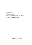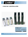
1
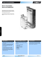
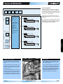
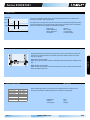
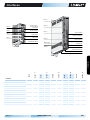
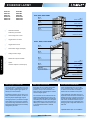
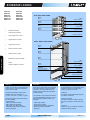
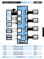
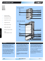
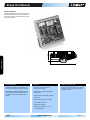
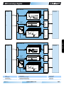
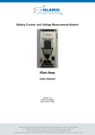
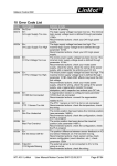
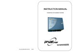
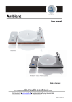
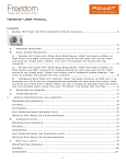
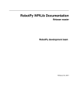
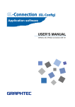
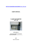
E100/1001 CONTROLLERS
Import Belgium & Luxembourg
Profilex s.a.
4A, Z.I. In den Allern
L-9911 Troisvierges
Tel: 00352/99 89 06
Fax: 00352/26 95 73 73
www.profilex-systems.com
[email protected]
The linear motor technology for industrial applications
Notes :
_____________________________________________________________________________________________________
_____________________________________________________________________________________________________
_____________________________________________________________________________________________________
_____________________________________________________________________________________________________
_____________________________________________________________________________________________________
_____________________________________________________________________________________________________
_____________________________________________________________________________________________________
_____________________________________________________________________________________________________
_____________________________________________________________________________________________________
_____________________________________________________________________________________________________
_____________________________________________________________________________________________________
_____________________________________________________________________________________________________
_____________________________________________________________________________________________________
_____________________________________________________________________________________________________
_____________________________________________________________________________________________________
_____________________________________________________________________________________________________
_____________________________________________________________________________________________________
_____________________________________________________________________________________________________
_____________________________________________________________________________________________________
__
The linear motor technology for industrial applications
Servo Controllers
Servo Controller
Series E100/E1001
The Series E100 servo controller and powerful
Series E1001 are compact, one, two or four-axis
position controllers with 16-bit position resolution
and integrated power elements.
E100/E1001
The controllers are suitable for simple and standard positioning tasks in the low to medium force
range.
Motor Interfaces
Connection to Machine Controller
Process Interfaces
Series E100 and E1001 servo controllers
allow control of up to four linear motors by
one controller.
The linear motors themselves are operated without any complicated peripherals,
such as end position monitors or reference switches.
The E100 and E1001 series servo controllers can be controlled through the following
interfaces:
As a fast process interface for direct reading
of sensor signals, one combined analog/digital input per drive is available as an analog
position target or a trigger input.
The individual linear motors are either
completely independently controlled, or
they are synchronized with each other in
special applications, in master booster or
master gantry mode.
232
•
•
•
•
•
•
•
Digital inputs and outputs
Analog Inputs
RS232 Serial Interface
RS485 Serial Interface
CANopen
DeviceNet
Profibus DP
www.LinMot.com
Edition 15
subject to change
Series E100/E1001
System Integration
Fieldbusses and interfaces to the overlaid control
Supply
Digital
I/O´s
RS232
RS485
Logic
Supply
Motor
Supply
CANopen
DeviceNet
Profibus
DP
Linmot
Servo Controller
Series
E100 / E1001
Process Inputs
Connection to the overlaid control is done via
analog and digital signals, a serial connection, or
fieldbusses.
Fmax = 200N
Position Controller:
• 16 Bit Position Value
• Resolution 20µm
Run Modes:
• VA Interpolated
Moves
• Analog Position
• Run Curves
• Two Point Trigger
Moves
Trigger
Inputs
Series E100/E1001 controllers are suitable for
controlling linear motors that are operated without optional peripherals such as reference and
end stop switches, external high-precision position sensors, or a holding brake.
The compact size is a great advantage of the Series E100/E1001 servo controllers, primarily for
compound and multi-axis applications, with regard to installation space and effort.
Fmax = 200N
Internal stored Curves:
• Max. 64 Curves
• Up to 4´000 set
points
Fmax = 200N
Analog
Inputs
E100/E1001
Config.
Fmax = 200N
RS232
Logic and Power Supply
Servo Controller E400 in use
Configuration
The servo controllers have two separate
power supplies for the logic and power elements.
Parameterization and configuration of the
servo controller is done via the RS232 interface on the front side.
In an E-stop and safe stop of the drive, only
the power element supply is cut off from the
controller. The logic supply and the controller continue to run.
The menu-drive Windows interface LinMot
Talk is used for configuration, with which up
to four Axis can be configured simultaneously on one controller. LinMot Talk provides extensive debugging tools, such as an
oscilloscope and an error inspector, for
simple and rapid start-up of the Axis.
This has the advantage that the controller
and linear motor do not need to be reinitialized when the machine is restarted, since
all process data, including the current position of the linear motor, are still up to date.
Edition 15
subject to change
www.LinMot.com
233
Operating Modes
Absolute & Relative Positioning Commands
Stroke [mm]
For direct position targets, using absolute or relative positioning, the desired position is
reached according to acceleration and velocity-limited motion profiles (VA interpolator). Positioning commands can be invoked via the serial interface, fieldbusses, ETHERNET, or the trigger input.
Goto 100mm
vmax = 2,5m/s
amax = 3,0m/s2
Time[ms]
Stroke range:
Position Resolution:
Velocity Resolution:
Acceleration:
±630mm
20µm (16 Bit)
1.0µm/s (16 Bit)
2
10.0µm/s (16 Bit)
Travel Along Time Curves
Stroke [mm]
E100/E1001
Start Curve 1
Up to 99 different time curves can be stored Series E1100 controllers, with up to 16,000 individual waypoints. The motor can thus travel along time curves of any complexity, such as
those generated by CAD programs and stored in the controller (Excel CSV format). The time
curves can be invoked via the serial interface, fieldbusses, ETHERNET, or the trigger input.
Curve 1
Time[ms]
Stroke range:
Position Resolution:
Motion profiles:
Curve points:
±630mm
20µm (16 Bit)
max. 64 curve profiles
max. 4’000points
Analog Position Target
For an analog position target, the linear motor travels to a position proportional to the input
voltage. The position is continuously read. In order to prevent uncontrolled jumps in position,
the motor travels to the positions with a programmable maximum acceleration and velocity
(VA interpolator).
0V
10V
Position Position
234
Inputs:
Voltage range:
Resolution:
Scanning rate:
www.LinMot.com
1 analog input per motor
0-10VDC
10 Bit
800µsec
Edition 15
subject to change
Series E100/E1001
Trigger 2 Point
Stroke[mm]
In the two-point trigger operating mode, two freely adjustable positions are controlled by the
overarching controller, using a trigger signal.
Pos 2
One target value for the high level, and one for the low level of the digital input signal are stored
in the drive electronics. If the signal at the drive electronics input changes, then the associated
position is moved to at the programmed acceleration and speed.
Pos 1
Trigger
Time [ms]
Stroke range:
Position Resolution:
Velocity Resolution:
Acceleration:
±630mm
20µm (16 Bit)
1.0µm/s (16 Bit)
2
10.0µm/s (16 Bit)
Using master-slave synchronization, two linear motors can be synchronized via a serial communications connection between two controllers, so that the overlaid controller can control
them as a single axis.
Master Gantry Synchronization
Master gantry synchronization is used for portal designs with two parallel Axis at different locations.
y
Master Booster Synchronization
Master booster synchronization is used to double the force when two motors are mechanically
rigidly connected to each other.
Internal Command Table
Command 1
Command 2
Command 3
Command 4
Command 5
...
...
Command 64
Edition 15
subject to change
Pos 125mm
Pos 250mm
Curve 1
Pos -30mm
Pos +12,5mm
Pos -12,5mm
Multi Trigger
With the Multi-Trigger-Table, up to 64 positions or independent travel commands can be
stored on the controller and addressed directly or indirectly via 4 digital inputs.
Digital inputs:
Interface:
Scanning rate:
www.LinMot.com
Max. 4
Sys2
800µsec
235
E100/E1001
X2
X1
Master Slave Synchronization
Configuration
LinMot Talk
E100/E1001
LinMot Talk configuration software is a Windows-based interface that supports the user during start-up and configuration of the LinMot
Series E100 and E1001 servo controllers. The
software has a powerful, modular, graphical interface that covers all the tasks surrounding the
LinMot servo controller. Great emphasis was
placed on a high level of user-friendliness during
development.
Start-up and Analysis Tools
Simple Installation
Integrated Documentation
Using the LinMot Talk PC interface, LinMot servo
controllers are configured. Additionally, the
drives can be monitored during operation with
the machine running, and the current motion sequences, as well as earlier warnings and error
messages, can be analyzed in detail (monitoring).
For start-up and monitoring, the servo controller
is connected to a PC via the RS232 interface on
the front, using a 9-pole D-sub connector (1:1
Connection). Up to four Axis on one controller
can be configured and monitored at the same
time using LinMot Talk.
After installation of LinMot Talk on the PC is complete, all manuals and installation instructions
are available via the Windows Start Menu. The
user thus always has the current documentation
available to him.
Parameterization
Optimization
Monitoring
Using the "Parameter Inspector," the controllers are parameterized in a simple manner. The user has a wide range of
adjustments available for operating modes,
error management, warning messages,
and regulating parameters. Entire parameter sets can be stored, loaded, and printed
out.
The integrated oscilloscope helps the user
during start-up and optimization of the drive system. Internal variables, such as the
target and actual position, can be shown in
real time on the screen, and then printed
out. The displayed data can be stored in
CSV format for further processing in MS
Excel, or stored for documentation purposes.
Using the "Error Inspector," the user can
read out stored errors, as well as the currently active warnings and error messages
in the LinMot servo controller. The last 10
error messages are stored in non-volatile
memory on the servo controller, together
with the operating hours counter.
The "Curve Editor" allows creation of travel
curves. In addition, existing curves can be
loaded, stored, edited, combined, and printed out. Further, complex motion sequences can be generated as desired in
MS Excel, and loaded into the controller.
236
www.LinMot.com
Further, the states of the inputs and outputs
can be viewed in the "Error Inspector." This
allows rapid and uncomplicated checking of
signals from and to the overlaid control.
Edition 15
subject to change
Interfaces
E4001-D
N-ME
1
1 Ph1+
red
2 Ph1-
Motor A
pink
Motor A
3 Ph2+
blue
4 Ph2-
grey
5 +5VD
C
6 AGND
white
inner shield
7 SIN
yellow
8 COS
10
black
LD outer
10 SHIE
shield
1
System Interface 1
Profibus Address
VF-Interface
Motor B
Motor B
Motor A
green
9 TEMP
10
System Interface 2
Profibus Interface
State
1
S2
F012
10
System Schnittstelle 1
Sys1
Supply
Motor /Logic
1
Motor D
Motor D
5 GND
9 CAN
H
RS/CAN Bus Address
8 CAN
3 RS23 L
2 Rx
7
2 RS23
2 Tx
6
1
MOT SUPPLY
Motor Supply
4
Regeneration
Resistor
COM / CONFIG
10
System Interface 2
Profibus Interface
Sys2
Motor D
S1
789A
CDE
B
COM Interface
Profibus Address
789A
56
34
H
(hex)
ID LOW
56
34
Motor C
ID HIG
CDE
B
Motor C
Motor C
F012
Motor B
PGND
PWR+
+
RR
-
COM Interface
Logic Supply
Logic Suppl
y
24 (22..5
0) VDC
Motor Suppl
y
72 (24..8
0) VDC
PE
+24VDC
DGND
Option Master Encoder
E1031-DP
E130-DP
E1001-DN
E100-DN
E1001-CO
E100-CO
E1001-MT
E100-MT
E1001-AT
E100-AT
E100/E1001
Option Master Encoder I/O’s
Interface
System Interface 1
System Interface 2
Profibus Address
Profibus Interface
COM Interface
Supply Motor
Supply Logic
Supply Logic/Motor
Regeneration Resistor
Bus Address RS/CAN
Motor Connector DSUB-9
Motor Connector MC01-P
Edition 15
subject to change
www.LinMot.com
237
E100/E1001-AT/MT
Series E100/E1001-AT/MT
E100-AT
E200-AT
E400-AT
E1001-AT
E2001-AT
E4001-AT
E100-MT
E200-MT
E400-MT
E1001-MT
E2001-MT
E4001-MT
E100, E200, E400-AT/MT
Mot A
Motor A
Sys 1
System Interface 1
Mot B
Motor B
Sys 2
System Interface 2
Mot C
Motor C
Com
COM Interface
Mot D
Motor D
PWR
Motor/Logic Supply
Absolute & Relative
Positioning Commands
RS/CAN Bus Address
Travel Along Time Curves
Trigger Mode: Two Point
E1001, E2001, E4001-AT/MT
E4001-
AT
1 Ph1+
red
2 Ph1-
pink
3 Ph2+
Mot A
Motor A
Motor A
Trigger Mode: Curves
1
blue
4 Ph2-
grey
5 +5VD
C
6 AGND
white
inner shield
7 SIN
yellow
8 COS
10
green
9 TEMP
10 SHIE
black
LD outer
shield
Internal Multi Trigger Table (MT)
Analog Position Target
Motor B
1
Mot B
Motor B
10
State
56
34
789A
S1
789A
56
34
(hex)
ID LOW
F012
S2
PWR Motor
Motor Power Supply
Regeneration Resistor
Sys 1
5 GND
9 CAN
H
10
4
8 CAN
3 RS23 L
2 Rx
7
2 RS23
2 Tx
6
1
Sys 2
System Interface 2
PGND
PWR+
+
RR
Motor Suppl
y
72 (24..8
0) VDC
Logic Suppl
y
24 (22..5
0) VDC
PE
+24VDC
DGND
COM / CONFIG
Mot D
Motor D
Sys 1
System Interface 1
Motor D
Option:
Customer-Specific Functions (MT)
1
Sys 2
10
MOT SUPPLY
E100/E1001-AT/MT
H
F012
ID HIG
CDE
B
Mot C
Motor C
CDE
B
Master-Slave Synchronization
Motor C
1
Com
COM Interface
PWR Logic
Logic Supply
Option Master Encoder
Option Master Encoder I/O’s
Analog Trigger Controller AT
Multi Trigger Controller MT
Serial Interface RS232/RS485
The target position is provided by the overlaid control (PLC, industrial PC) as analog
position signals, digital trigger signals, or
directly via a serial interface.
Multi trigger servo controllers allow direct
programming of complex motion sequences, with up to 64 commands. The
servo controller is actuated by the overlaid
control via digital signals.
Series E100/E1001E1001-AT and -MT
servo controllers offfer an ASCII protocol
for serial communication over RS232 /
RS484 with the overlaid control system.
End positions stored in the AT servo controller, or stored travel profiles, can be invoked using simple digital trigger signals.
The target position is provided as a voltage
at the analog input of the servo controller.
The position range associated with the voltage range at the analog input can be freely
configured by the user.
The commands for the individual Axis are
stored in the state table in the servo controller. The individual states in the table are
controlled by the overlaid control via digital
signal addressing. As soon as a state is invoked by the overlaid control, the Axis carry out their defined motion or defined
command.
The E100/E1001 controllers have two independent serial interfaces for RS232 and
RS485. If the servo controller communicates with the RS485 interface with the overlaid control, the RS232 interface may be
used the same time for configuration and
debugging with configuration software LinMot Talk.
Adjustable Baud rates: 9.6-115.2kBaud
238
www.LinMot.com
Edition 15
subject to change
Analog- / Multi-Trigger
E100-AT/MT
E1001-AT/MT
5...24VDC
SYS1
MOT A
PH1+
PH1PH2+
PH2+5V
GND
SIN
COS
TEMP
WARNING
ERROR
POS. ERROR
MSG / OUT4
OUT5
OUT6
STOP+
STOPFREEZE+
FREEZEDIGIN 5/6
OVERARCHING
CONTROLLER
DIGITAL SIGNALS:
5V TTL, 24VDC
ANALOG SIGNALS:
0 ... 10V
LINEAR MOTOR A
SYS2
TRIG/ANALOG IN 1
TRIG/ANALOG IN 2
TRIG/ANALOG IN 3
TRIG/ANALOG IN 4
RUN+
RUNINIT+
INITGND
MOT B
PH1+
PH1PH2+
PH2+5V
GND
SIN
COS
TEMP
LINEAR MOTOR B
COM
3
RS232 PC CONFIG.
INTERFACE
RS232
RS485
4
RS232 / RS 485
9.6 kBaud
COMMUNICATION
MOT C
MOTOR POWER
SUPPLY
24..48VDC
PWR
E100
2-PHASE POWER
STAGE
24...48VDC 3A
PHASE CURRENT
PH1+
PH1PH2+
PH2+5V
GND
SIN
COS
TEMP
LINEAR MOTOR C
E100/E1001-AT/MT
SUPPLY E100
SIGNAL POWER
SUPPLY
24..48VDC
MOT D
SUPPLY E1001
MOTOR POWER
SUPPLY
24..48VDC
PWR
E1001
2-PHASE_POWER
STAGE
24...80VDC 6A
PHASE CURRENT
SIGNAL POWER
SUPPLY
24..48VDC
PH1+
PH1PH2+
PH2+5V
GND
SIN
COS
TEMP
LINEAR MOTOR D
ID
RS/CAN BUS ADDRESS
ID LOW
ID HIGH
Item
E100-AT
E200-AT
E400-AT
E1001-AT
E2001-AT
E4001-AT
Description
AnalogTrigger Controller 1 Axis (48V/3A)
AnalogTrigger Controller 2 Axis (48V/3A)
AnalogTrigger Controller 4 Axis (48V/3A)
AnalogTrigger Controller 1 Axis (72V/8A)
AnalogTrigger Controller 2 Axis (72V/8A)
AnalogTrigger Controller 4 Axis (72V/8A)
Part Number
0150-1601
0150-1602
0150-1604
0150-2300
0150-2301
0150-2303
E100-MT
E200-MT
E400-MT
E1001-MT
E2001-MT
E4001-MT
Multi Trigger Controller 1 Axis (48V/3A)
Multi Trigger Controller 2 Axis (48V/3A)
Multi Trigger Controller 4 Axis (48V/3A)
Multi Trigger Controller 1 Axis (72V/8A)
Multi Trigger Controller 2 Axis (72V/8A)
Multi Trigger Controller 4 Axis (72V/8A)
0150-1611
0150-1612
0150-1614
0150-2304
0150-2305
0150-2307
Edition 15
subject to change
www.LinMot.com
239
E100/E1001-CO/DN
Series E100/E1001-CO/DN
E100-CO
E200-CO
E400-CO
E1001-CO
E2001-CO
E4001-CO
E100-DN
E200-DN
E400-DN
E1001-DN
E2001-DN
E4001-DN
E100, E200, E400-CO/DN
CO
Mot A
Motor A
Sys 1
System Interface 1
Mot B
Motor B
Sys 2
System Interface 2
Mot C
Motor C
Com
COM Interface
Mot D
Motor D
PWR
Motor/Logic Supply
Absolute & Relative
Positioning Commands
RS/CAN Bus Address
Travel Along Time Curves
Trigger Mode: Two Point
E1001, E2001, E4001-CO/DN
E4001-
CO
1 Ph1+
red
2 Ph1-
pink
3 Ph2+
Mot A
Motor A
Motor A
Trigger Mode: Curves
1
blue
4 Ph2-
grey
5 +5VD
C
6 AGND
white
inner shield
7 SIN
yellow
8 COS
10
green
9 TEMP
10 SHIE
black
LD outer
shield
Internal Command Table
Analog Position Target
Motor B
1
Mot B
Motor B
10
State
56
34
789A
S1
789A
56
34
(hex)
ID LOW
F012
S2
PWR Motor
Motor Power Supply
Regeneration Resistor
Sys 1
Mot D
Motor D
5 GND
9 CAN
H
10
4
8 CAN
3 RS23 L
2 Rx
7
2 RS23
2 Tx
6
1
Sys 2
System Interface 2
PGND
PWR+
+
RR
Motor Suppl
y
72 (24..8
0) VDC
Logic Suppl
y
24 (22..5
0) VDC
PE
+24VDC
DGND
COM / CONFIG
Option:
Customer-Specific Functions
Sys 1
System Interface 1
Motor D
1
Sys 2
10
MOT SUPPLY
E100/E1001-CO/DN
H
F012
ID HIG
CDE
B
Mot C
Motor C
CDE
B
Master-Slave Synchronization
Motor C
1
Com
COM Interface
PWR Logic
Logic Supply
Option Master Encoder
Option Master Encoder I/O’s
CANopen
DeviceNet
LinMot CO controllers, with integrated CANopen interface, support the CiA DS301
communication profile.
Series DN controllers feature an integrated
DeviceNet interface. With the DeviceNet
interface, even complicated motion sequences can be realized with the highest
possible flexibility.
The following CANopen resources are
available on the CO controllers: 1-5
T_PDO, 1-5 R_PDO 1 T_SDO, 1 R_SDO
The following protocols are supported by
the CO controllers:
- Node Guarding
- PDO acyclic with inhibit time
- SDO Upload and Download
- NMT (Start, Stop, Enter PreOp,
Reset Node, Reset Communication)
- Boot-Up Message
240
The controller can be actuated and monitored via the DeviceNet connection. The following expanded fieldbus functions are
available:
- Direct target position
- Invoke motion profiles
- Read and write access to parameters
- Monitoring internal parameters
- Diagnosis
www.LinMot.com
"Explicit Messaging" The DeviceNet Servo
Controllers support one "Explicit Messaging" connection per master.
"Polled IO"
The master initiates data interchange with
a "Polled IO" command.
"Change of State IO"
With this connection, the data is transferred only if the states or values have changed.
"Cyclic IO"
With the "Cyclic IO" connection, the data is
transferred strictly cyclically.
Edition 15
subject to change
CANopen / DeviceNet
E100-CO/DN
E1001-CO/DN
5...24VDC
SYS1
MOT A
PH1+
PH1PH2+
PH2+5V
GND
SIN
COS
TEMP
WARNING
ERROR
POS. ERROR
MSG / OUT4
OUT5
OUT6
STOP+
STOPFREEZE+
FREEZEDIGOUT 5/6
OVERARCHING
CONTROLLER
DIGITAL SIGNALS:
5V TTL, 24VDC
ANALOG SIGNALS:
0 ... 10V
SYS2
TRIG/ANALOG IN 1
TRIG/ANALOG IN 2
TRIG/ANALOG IN 3
TRIG/ANALOG IN 4
RUN+
RUNINIT+
INITGND
COM
RS232 PC CONFIG.
INTERFACE
RS232 / RS 485
9.6 kBaud
COMMUNICATION
LINEAR MOTOR A
3
4
2
MOT B
PH1+
PH1PH2+
PH2+5V
GND
SIN
COS
TEMP
LINEAR MOTOR B
RS232
RS485
CAN
CAN: CANOPEN
DEVICENET
max. 500kBaud
MOT C
MOTOR POWER
SUPPLY
24...48VDC
PWR
E100
2-PHASE
POWER STAGE
24...48VDC
3A PHASE
CURRENT
PH1+
PH1PH2+
PH2+5V
GND
SIN
COS
TEMP
LINEAR MOTOR C
E100/E1001-CO/DN
SUPPLY E100
SIGNAL POWER
SUPPLY
24...48VDC
SUPPLY E1001
MOTOR POWER
SUPPLY
48...72VDC
PWR
E1001
2-PHASE
POWER STAGE
24...80VDC
6A PHASE
CURRENT
SIGNAL POWER
SUPPLY
24...48VDC
MOT D
PH1+
PH1PH2+
PH2+5V
GND
SIN
COS
TEMP
LINEAR MOTOR D
ID
CAN BUS ADDRESS
ID LOW
ID HIGH
Item
E100-CO
E200-CO
E400-CO
E1001-CO
E2001-CO
E4001-CO
Description
CanOpen Controller 1 Axis (48V/3A)
CanOpen Controller 2 Axis (48V/3A)
CanOpen Controller 4 Axis (48V/3A)
CanOpen Controller 1 Axis (72V/8A)
CanOpen Controller 2 Axis (72V/8A)
CanOpen Controller 4 Axis (72V/8A)
Part Number
0150-1669
0150-1670
0150-1672
0150-2308
0150-2309
0150-2311
E100-DN
E200-DN
E400-DN
E1001-DN
E2001-DN
E4001-DN
DeviceNet Controller 1 Axis (48V/3A)
DeviceNet Controller 2 Axis (48V/3A)
DeviceNet Controller 4 Axis (48V/3A)
DeviceNet Controller 1 Axis (72V/8A)
DeviceNet Controller 2 Axis (72V/8A)
DeviceNet Controller 4 Axis (72V/8A)
0150-1641
0150-1642
0150-1644
0150-2312
0150-2313
0150-2315
Edition 15
subject to change
www.LinMot.com
241
E130/E1031-DP
Series E130/E1031-DP
E130-DP
E230-DP
E430-DP
E1031-DP
E2031-DP
E4031-DP
E4001-MT
E130, E230, E430-DP
Mot A
Motor A
ID
Profibus Bus Address
Mot B
Motor B
DP
Profibus Interface
Mot C
Motor C
Com
COM Interface
Mot D
Motor D
PWR
Motor/Logic Supply
Absolute & Relative
Positioning Commands
Travel Along Time Curves
Trigger Mode: Two Point
E1031, E2031, E4031-DP
E4001-
DP
1 Ph1+
red
2 Ph1-
pink
3 Ph2+
Mot A
Motor A
Motor A
Trigger Mode: Curves
1
blue
4 Ph2-
grey
5 +5VD
C
6 AGND
white
inner shield
7 SIN
yellow
8 COS
10
green
9 TEMP
10 SHIE
black
LD outer
shield
Internal Command Table
Analog Position Target
Motor B
1
Mot B
Motor B
10
State
789A
56
34
H
F012
ID HIG
S1
789A
56
34
(hex)
ID LOW
CDE
B
F012
Mot C
Motor C
CDE
B
Master-Slave Synchronization
Motor C
1
ID
Profibus Bus Address
S2
PWR Motor
Motor Power Supplyen
Regeneration Resistor
4
8 CAN
3 RS23 L
2 Rx
7
2 RS23
2 Tx
6
1
PGND
PWR+
+
RR
Motor Suppl
y
72 (24..8
0) VDC
Logic Suppl
y
24 (22..5
0) VDC
PE
+24VDC
DGND
PROFIBUS DP
5 GND
9 CAN
H
10
COM / CONFIG
Mot D
Motor D
Motor D
1
Option:
Customer-Specific Functions
MOT SUPPLY
E100/E1001-DP
10
DP
Profibus Interface
Com
COM Interface
PWR Logic
Logic Supply
Option Master Encoder
Option Master Encoder I/O’s
Profibus DP
Series DP servo controllers feature an integrated PROFIBUSDP interface. PROFIBUS-DP provides the user with a
standardized fieldbus interface for rapid
data interchange between the servo controller and the overlaid control.
With cyclical provision of target positions
and other process data, the Profibus controllers are the ideal solution for applications with motions and sequences that
change frequently, such as are required,
for example, in flexible machines and systems for rapid format changes.
242
The Profibus interface supports all Baud
rates from 9.6 Kbits/s to 12 Mbit/s. The maximum net data quantity exchanged in cyclical data traffic is 64 bytes per cycle. The
smallest achievable bus cycle time is 100
µs. The structure and scope of cyclical data
can be collected from any individual data
modules into an overall data quantity when
planning the system, whereby the data for
the individually connected motors can be
different.
A GSD device master file is provided for
open planning in conformance with the
standard.
www.LinMot.com
The front-side 9-pin DSUB bus connector
meets the PROFIBUS standard. It provides
power for an external bus termination. A
positive directional control signal is provided to control repeaters or optical fibers.
All signals on the PROFIBUS connector
are galvanically separated.
The PROFIBUS-DP address is set by two
hex code switches (ID1 and ID2). All
addresses permitted by the standard are
supported (0..125).
Edition 15
subject to change
Profibus DP
E130-DP
E1031-DP
MOT A
PH1+
PH1PH2+
PH2+5V
GND
SIN
COS
TEMP
ID HIGH
ID LOW
LINEAR MOTOR A
DP
5
PROFIBUS ID
PROFIBUS DP
COMMUNICATION
max. 12MBaud
MOT B
PH1+
PH1PH2+
PH2+5V
GND
SIN
COS
TEMP
COM
3
SUPPLY E130
MOTOR POWER
SUPPLY
24...48VDC
RS232
PWR
E130
-PHASE
POWER STAGE
24...48VDC
3A PHASE
CURRENT
SIGNAL POWER
SUPPLY
24...48VDC
SUPPLY E1031
MOTOR POWER
SUPPLY
48...72VDC
PWR
Edition 15
subject to change
PH1+
PH1PH2+
PH2+5V
GND
SIN
COS
TEMP
LINEAR MOTOR C
E1031
2-PHASE
POWER STAGE
24...80VDC
6A PHASE
CURRENT
MOT D
SIGNAL POWER
SUPPLY
24...48VDC
Item
E130-DP
E230-DP
E430-DP
E1031-DP
E2031-DP
E4031-DP
MOT C
E100/E1001-DP
RS232 PC CONFIG.
INTERFACE
RS232 / RS 485
9.6 kBaud
LINEAR MOTOR B
PH1+
PH1PH2+
PH2+5V
GND
SIN
COS
TEMP
Description
Profibus DP Controller 1 Axis (48V/3A)
Profibus DP Controller 2 Axis (48V/3A)
Profibus DP Controller 4 Axis (48V/3A)
Profibus DP Controller 1 Axis (72V/8A)
Profibus DP Controller 2 Axis (72V/8A)
Profibus DP Controller 4 Axis (72V/8A)
www.LinMot.com
LINEAR MOTOR D
Part Number
0150-1621
0150-1622
0150-1624
0150-2316
0150-2317
0150-2319
243
Break Out Module
Break Out Module
The Break Out Module for the AT and MT servo
controllers leads all input and output signal from
the SYS1 and SYS2 DSUB connectors to plugtype screw terminals.
Break Out Modul
48 mm
Break Out Modul
126 mm
Break Out Module
Features:
Cable & Connector Set
The Break Out Module is available in two
versions, with a digital or analog interface.
- Plug-type screw terminals for
all inputs and outputs
The connection cable to the servo controller and the plug-type screw terminals are
available as a set.
The Break Out Module is snapped onto the
DIN rail directly in the electrical enclosure.
Two tabs for screw mounting are also included.
- Digital inputs, galvanically isolated,
(24V/10mA)
- Digital outputs, galvanically isolated,
(24V/0.5A)
- Relay output (48V/2A, max. 60W)
- LED status indicator for
all inputs and outputs
- Analog input voltage -10…+10V
for analog module.
244
www.LinMot.com
Edition 15
subject to change
M01-analog/-digital
M01-DIGITAL
J1
SYS1
+ 5V
15
+ 5V
SYS1
In+
Out-
STOP
FREEZE
INIT
RUN
Galvanically
Isolated
on LinMot
Servo Controller
SYS1
RUN+
9
RUN-
SYS2
OUT 6
OUT 5
OUT 4
OUT 3
OUT 2
OUT 1
J4
+ 5V
R Closer
R Opener
R In
+ 5V
+ 24V + 24V
Out1
M01-ANALOG
SYS1
+ 5V
15
+
SYS1
/2
-
-1
STOP
FREEZE
INIT
RUN
Galvanically
Isolated
on LinMot
Servo Controller
RUN+
9
RUN-
SYS2
OUT 6
OUT 5
OUT 4
OUT 3
OUT 2
OUT 1
J4
+ 5V
R Closer
R Opener
R In
+ 5V
+ 24V + 24V
Out1
Item
M01-digital
M01-analog
M01-Connector
Edition 15
subject to change
OVERARCHING
CONTROLLER
11
J2
RUN+
RUNINIT+
INITFREEZE+
FREEZESTOP+
STOP-
8
J3
GND
+24V
OUT1
OUT2
OUT3
OUT4
OUT5
OUT6
GND
R_OPENER
R_IN
R_CLOSER
11
J1
TRIG IN 4
TRIG IN 3
TRIG IN 2
TRIG IN 1
LINMOT SERVO
CONTROLLER
SYS1
AGND
GND
+24V
IN1+
IN1IN2+
IN2IN3+
IN3IN4+
IN4-
Break Out Modul
TRIG IN 4
TRIG IN 3
TRIG IN 2
TRIG IN 1
LINMOT SERVO
CONTROLLER
Description
Breakout Module digital
Breakout Module analog
Cable and Connector set
www.LinMot.com
AGND
GND
+24V
IN1+
IN1IN2+
IN2IN3+
IN3IN4+
IN4-
OVERARCHING
CONTROLLER
11
J2
RUN+
RUNINIT+
INITFREEZE+
FREEZESTOP+
STOP-
8
J3
GND
+24V
OUT1
OUT2
OUT3
OUT4
OUT5
OUT6
GND
R_OPENER
R_IN
R_CLOSER
11
Part Number
0150-1932
0150-1933
0150-1934
245
Interfaces
E100
Supply Motor/Logic
GND internally connected
to controller housing
Internal Fuse
500mAT
PWR SIGNAL +
1
2
3
1
GND
GND
2
PWR MOTOR +
24...48VDC
24...48VDC
3
Internal Fuse
10AT
Supply GND must be
externally connected to
earth (Ground Bus)
Power Connector
Logic/Motor
1.5 mm² (AWG16)
Supply
Supply Voltage Logic:
Supply Voltage Motor:
24...48VDC (absolute max. Rating 48VDC + 10%)
24...48VDC (absolute max. Rating 48VDC + 10%)
Motor Supply GND must be externally connected to earth
- By exceeding 52VDC supply voltage, the controller will go into error state.
- Power supply connectors must not be connected or disconnected while DC voltage is present.
E1001
Supply Motor/Logic
E100/E1001
Optional:
external Regeneration Resistor
RR01-10/60
PGND
PWR+
1
RR -
2
RR +
GND
1
2
3
+
RR
-
PWR +
4
24...80VDC
3
PGND
GND
4
GND internally connected
to controller housing
Screw Terminals
2.5 mm² (AWG14)
GND internally
connected to
controller
housing
LOGIC SUPPLY 24V
1
GND
2
Internal Fuse
3AT
1
2
22...50VDC
GND
3
Phoenix MC1,5/2-STF-3.81
0.25-1.5mm² (AWG24-16)
Supply GND must be
externally connected to
earth (Ground Bus)
Supply:
Supply Voltage Logic:
Supply Voltage Motor:
24...80VDC (absolute max. Rating 92VDC)
48...72VDC (absolute max. Rating 72VDC + 5%)
Motor and Logic Supply GND must be externally connected to earth
- By exceeding 92VDC motor supply voltage, the controller will go into error state.
- By exceeding 52VDC logic supply voltage, the controller will go into error state.
- Power supply connectors must not be connected or disconnected while DC voltage is present.
- It is recommended that the motor and the logic be supplied and controlled separately.
246
www.LinMot.com
Edition 15
subject to change
Series E100/E1001
Mot A (B, C, D)
1
2
3
4
5
Motor connector E100
6
7
8
9
DSUB-9 (f)
RED
PHASE 1+
PINK
PHASE 1-
BLUE
PHASE 2+
GREY
PHASE 2-
WHITE
+5VDC
INNER SHIELD
AGND
YELLOW
SINE
GREEN
COSINE
BLACK
TEMP.
1
6
2
7
3
GND
8
4
2k2
9
5
2k2
10k
GND
GND
+5VDC
Outer shield connected to connector housing
Motor Cable
Motor connector E1001
1
RED
PHASE 1+
2
PINK
PHASE 1-
BLUE
PHASE 2+
GREY
PHASE 2-
WHITE
+5VDC
7
INNER SHIELD
AGND
8
YELLOW
SINE
9
GREEN
COSINE
10
BLACK
TEMP.
3
4
5
6
Outer shield connected to connector housing
MC01-P/f
1
2
3
4
+5VDC
5
GND
6
7
2k2
8
2k2
9
10k
GND
GND
E100/E1001
Mot A (B, C, D)
+5VDC
10
Motor Cable
Motor Cable
- Use only special double-shielded Linear Motor Cable (see motor accesories).
- LinMot offers a wide range of preassambled motor cable in standard and custom length (tested 1.5kV):
Standard Cable K05-...
High-Flex Cable KS05-...
Robot-Cable KR05-...
- Do NOT connect AGND (Pin 6) to ground or earth!
- Inner shield (AGND) and outer shield (earth) must be isolated to each other.
- Use +5V (Pin 3) and AGND (Pin 6) only for motor internal Hall Sensor supply (max. 100mA).
- Wrong Motor wiring may damage Linear Motors and/or Servo Controller.
If you are assembling motor cables by your own, double check motor wiring carefully before power up.
- Do not connect or disconnect the motors from controllers with voltage present.
Wait to connect or disconnect motors until all LinMot controller LED’s have turned off.
Edition 15
subject to change
www.LinMot.com
247
Interfaces
SYS1
System interface 1
5...24VDC
WARN OUT
ERROR OUT
POS ERROR / DIG OUT 3
MSG / DIG OUT 4
DIG OUT 5
1
2
3
4
5
11
12
13
14
15
DIG OUT 6
EMERGENCY STOP +
EMERGENCY STOP FREEZE +
FREEZEDIG IN 5
DIG IN 6
DSUB-15 (f)
DO NOT CONNECT!
OUTPUT +5V (max 50 mA)
GND
14
13
11
12
10
6
2
1
3
7
4
100k
8
100k
9
5V
5
GND
15
E100/E1001
Control Inputs: Stop (active low) / Freeze (active high)
Optical isolated inputs (Input voltage: 0 …. 24V)
- for logical zero: input voltage < 2V
- for logical one: input volateg > 3.5V
Input current: < 20 mA (internally limited to 20 mA)
Update rate: 1.6 ms
Digital Inputs: Dig In 5 / Dig In 6
24VDC inputs, input resistance 100kOhm
- for logical zero: input voltage < 2V
- for logical one: input volateg > 3.5V
Digital Outputs: Pos Error Out / MSG / Error Out / Warn Out / Dig Out 5 / Dig Out 6
Open Collector max 24V / 50 mA
Typical pull-up Resistor R:for V+ = 5V supply: R=150 Ohm/0.25 W
for V+=24V supply: R=820 Ohm / 1W
SYS2
System interface 2
TRIG/ANLOG IN 1
1
TRIG/ANLOG IN 2
5
4
3
2
1
9
8
7
6
TRIG/ANLOG IN 3
6
2
TRIG/ANLOG IN 4
RUN +
GND
100k
GND
GND
GND
GND
3
8
4
INT -
DSUB-9 (m)
100k
100k
7
RUN INT +
100k
9
5
GND
Digital/Analog Input: Trig/Analog IN
Input can be used as analog inputs between 0 … 10V (10 bit resolution) input resistance 100kOhm
or digital inputs (max. 24V, input resistance 100kOhm) for logical zero <2V,
for logical one >3.5V
Control Inputs: RUN (active high) / INIT (active high)
Optical isolated 24V inputs
Input voltage: 0 …. 24V
for logical zero <2V
for logical one >3.5V
Input current: < 20 mA (internally limited to 20 mA)
Update rate: 1.6 ms
248
www.LinMot.com
Edition 15
subject to change
Series E100/E1001
DP
Profibus DP interface
1
+ 5 V (ISOLATED)
1
2
3
4
5
6
7
8
9
6
2
7
RxD/TxD-P
3
RxD/TxD-N
8
CNTR-P
4
9
DSUB-9 (f)
GND (ISOLATED)
5
Isolated 5V output: max 50 mA
Com interface
RS485_TX+
5
4
3
2
1
9
8
7
6
RS232_TX
GND
RS485_TX-
7
RS232_RX
3
CAN_L
8
RS485_RX+
4
CAN_H
DSUB-9 (m)
RS232_TX
2
CAN_L
RS485_RX+
RS485_RX-
6
RS485_TXRS232_RX
RS485_TX+
1
RS485_RX-
CAN_H
9
5
100
GND
E100/E1001
COM
RS232: Configuration on all Controllers: use 1:1 connection cable to PC
LED
State display E100
Green
Yellow
Stat A Yellow:
STAT A : Coding for the actual operating state
The display of the various operating states is shown on the last page of this manual.
Stat B Yelllow:
STAT B: Coding for the actual operating state
The display of the various operating states is shown on the last page of this manual.
Yellow
Red
DISPLAY
Ready Green:
READY: The system has started correctly
Fault Red:
FAULT: An error has occurred
(In the state ERROR a blink code of the STAT LEDs A and B tells what the actual error is.
The blink codes are explained in chapter ‘Service’of the user Manual.)
State display E1001
8 Segement Display
Output of operating states and error codes
Edition 15
subject to change
www.LinMot.com
249
Accessories E100/E1001
Switched-Mode Power Supplies
E100/E1001 Accessories
Item
S01-48/300
S01-72/300
S01-72/600
SM01-300
SM01-600
115VAC / 230VAC
Description
Switched-Mode Power Supply 48V/300W for Controller Series E100
Switched-Mode Power Supply 72V/300W for Controller Series E1001
Switched-Mode Power Supply 72V/600W for Controller Series E1001
Mounting part for 300W Switched-Mode Power Supply
Mounting part for 600W Switched-Mode Power Supply
Transformer Supply T01
Item
T01-72/420...1500-Multi
250
Part Number
0150-1941
0150-1942
0150-1943
0150-3040
0150-3041
3x230/280/400/480VAC
Description
Transformer Supply 3x230/280/400/480VAC, 50/60Hz, 420...1500W
www.LinMot.com
Part Number
see page 328
Edition 15
subject to change
Accessories E100/E1001
Control Box B01-04
Description
Control Box for E100/E1001-AT/MT (230VAC, incl. cable and connectors)
Control Box for E100/E1001-AT/MT (115VAC, incl. cable and connectors)
Part Number
0150-1930
0150-1931
E100/E1001 Accessories
Item
B01-04 230VAC/50Hz
B01-04 115VAC/60Hz
COM connection cables and USB-converter
Item
RS232 PC cable
USB-RS232 converter
Edition 15
subject to change
Description
PC - RS232 connection cable for configuation (1.5m, 9 pin DSUB, f/f, 1:1)
USB-RS232 converter (0.3m, USB-9 pin DSUB, f)
www.LinMot.com
Part Number
0150-3009
0150-3110
251
Dimensions
178
119
330
Centers
194
Centers
315
210
A
89 B
12
F0 3
ID HIG
4567
12
F0 3
ID LOW
S1
A
89 B
CDE
(hex)
CDE
H
4567
296
176
S2
ly
Logic Supp
0) VDC
24 (22..5
E100/E1001
+24VDC
DGND
55
70
58
Dimensions in mm
E100
E200
E400
E1001
E2001
E4001
Interfaces
Width
mm
70
58
Height
mm
210
330
Height without fixings
mm
175
296
Depth
mm
Weight
kg
Protection Class
IP
40
40
Storage Temperture
°C
-25..70
-25..70
Operating Temperature
°C
0..50
0..50
Max. Case Temperature
°C
65
Max. Power Dissipation
W
Distance between Controllers
mm
252
120
1.1
22
1.2
38
50
www.LinMot.com
178
1.3
2. 5
2.6
2.7
65
70
80
50
Edition 15
subject to change
Item
E100-AT
E200-AT
E400-AT
E1001-AT
E2001-AT
E4001-AT
Description
AnalogTrigger Controller 1 Axis (48V/3A)
AnalogTrigger Controller 2 Axis (48V/3A)
AnalogTrigger Controller 4 Axis (48V/3A)
AnalogTrigger Controller 1 Axis (72V/8A)
AnalogTrigger Controller 2 Axis (72V/8A)
AnalogTrigger Controller 4 Axis (72V/8A)
Part Number
0150-1601
0150-1602
0150-1604
0150-2300
0150-2301
0150-2303
E100-MT
E200-MT
E400-MT
E1001-MT
E2001-MT
E4001-MT
Multi Trigger Controller 1 Axis (48V/3A)
Multi Trigger Controller 2 Axis (48V/3A)
Multi Trigger Controller 4 Axis (48V/3A)
Multi Trigger Controller 1 Axis (72V/8A)
Multi Trigger Controller 2 Axis (72V/8A)
Multi Trigger Controller 4 Axis (72V/8A)
0150-1611
0150-1612
0150-1614
0150-2304
0150-2305
0150-2307
E130-DP
E230-DP
E430-DP
E1031-DP
E2031-DP
E4031-DP
Profibus DP Controller 1 Axis (48V/3A)
Profibus DP Controller 2 Axis (48V/3A)
Profibus DP Controller 4 Axis (48V/3A)
Profibus DP Controller 1 Axis (72V/8A)
Profibus DP Controller 2 Axis (72V/8A)
Profibus DP Controller 4 Axis (72V/8A)
0150-1621
0150-1622
0150-1624
0150-2316
0150-2317
0150-2319
E100-DN
E200-DN
E400-DN
E1001-DN
E2001-DN
E4001-DN
DeviceNet Controller 1 Axis (48V/3A)
DeviceNet Controller 2 Axis (48V/3A)
DeviceNet Controller 4 Axis (48V/3A)
DeviceNet Controller 1 Axis (72V/8A)
DeviceNet Controller 2 Axis (72V/8A)
DeviceNet Controller 4 Axis (72V/8A)
0150-1641
0150-1642
0150-1644
0150-2312
0150-2313
0150-2315
E100-CO
E200-CO
E400-CO
E1001-CO
E2001-CO
E4001-CO
CanOpen Controller 1 Axis (48V/3A)
CanOpen Controller 2 Axis (48V/3A)
CanOpen Controller 4 Axis (48V/3A)
CanOpen Controller 1 Axis (72V/8A)
CanOpen Controller 2 Axis (72V/8A)
CanOpen Controller 4 Axis (72V/8A)
0150-1669
0150-1670
0150-1672
0150-2308
0150-2309
0150-2311
Edition 15
subject to change
www.LinMot.com
E100/E1001
Ordering Information
253