1
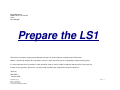
Nash Motorsports
BMW E36 LS1 Conversion
Part 2
Rev 30Aug05
Prepare the LS1
Follow these instructions step by step and by the end your LS1 will be ready for marriage to your E36 bimmer.
While it is possible to complete this prep work in a day it is more realistic to plan on 2-3 good days to get everything ready.
It is best to print out these instructions in black and white. Color is nice but it takes a long time and you will burn up a lot of ink.
If there are any questions, please call. I am here to help and want your swap to be a fantastic experience!
Sincerely,
Mike Collins
586-943-6385
Nash Motorsports
E36 LS1 Conversion
Part 2 – Prep the LS1
Last printed 7/1/2006 6:07:00 PM
Page - 1 -
In 1996 government regulations required all vehicles to be equipped with an emissions standard called
“onboard diagnostics 2” or OBD II. This standard requires the engine management system to perform
many tests on the emissions systems to determine proper function. One of the tests the PCM performs
is the catalytic converter function. This function is checked by comparing oxygen levels in the exhaust
gas before the cat and then after the cat. If the PCM determines the cat to be bad the vehicle will be
placed in “limp home mode”. Additionally the LS1 has a vehicle antitheft system (VATS) that requires
the body computer to send an “OK to start” signal to the PCM.
In this swap we have made no attempt to have an OBD II emissions compliant vehicle. As a result the
LS1 PCM needs to either fooled into running or reprogrammed. The PCM can be fooled into running by
using a VATS / dual O2 simulator. This simulator will send an “OK to start” signal to the PCM and will
send after cat O2 signal to the PCM that indicated proper cat function. With these two systems fooled,
the LS1 will start and run in full power mode.
Using the VATS / dual O2 simulator will not provide the PCM with information on the other emission
systems that are disabled. To the best of my knowledge the other systems being disabled will not put
the PCM into “limp home” mode but will cause the PCM to throw a bunch of codes and set the “check
engine” light.
The better solution is to have the PCM reprogrammed to eliminate checking systems that are no longer
functional. Doing this will allow the PCM the check the rest of the engine management systems for
proper function and set the light only when needed.
Nash Motorsports
E36 LS1 Conversion
Part 2 – Prep the LS1
Last printed 7/1/2006 6:07:00 PM
Page - 2 -
Note: In these instructions all references to pin locations on the LS1 connectors are for the f-body computers. There are
two version of these computers: 1998 or 1999 and newer. If you are using a computer from a corvette of GTO you will
have to reference the GM service manual to obtain wiring information.
1
2
3
Remove factory motor mounts from side of motor
Install new motor mount struts and torque to 65 Nm
Grind shifter as shown in picture.
Shifter tower.JPG
Nash Motorsports
E36 LS1 Conversion
Part 2 – Prep the LS1
Last printed 7/1/2006 6:07:00 PM
Page - 3 -
4
5
6
7
8
9
10
11
12
13
Remove shifter from transmission
Remove accessory drive belt
Remove alternator
Remove exhaust manifolds but save gaskets
For 1997 – 2001 motors, remove EGR plumbing (EGR valve can be removed from intake but hole will need to be plugged).
Remove AIR plumbing.
Cut transmission clutch line to 8" and install -4 female end fitting onto steel braided clutch line. To keep the steel braid from fraying,
wrap the clutch line with several layers of electrical tape at the cut location and use a die grinder with cutoff wheel and cut through the
tape and clutch line.
Install headers and check fit. Some motors have a plastic shield near the starter that will need to be cut away to allow room for the
headers. Torque header bolts to 35 N-m
Factory exhaust manifold gaskets are excellent. To he positive there is no leaks I recommend applying a coating of high temperature
RTV to both sides of the gasket prior to header installation.
Wrap starter in thermal protection blanket.
Nash Motorsports
E36 LS1 Conversion
Part 2 – Prep the LS1
Last printed 7/1/2006 6:07:00 PM
Page - 4 -
14
15
16
Remove electrical connector from Back Up light switch located on passenger side of transmission.
There is not enough room for the long back up light connector so wires need to be soldered to the switch terminals and 2 pin inline
connector installed. To do this first trim away the connector shield to expose copper connector. Then solder wires from new 2 pin inline
connector to these terminals.
Connect other side of inline connector to the backup light wires using crimp connectors. Protect wires with shrink tube and wire loom.
Backup switch trimmed.JPG
Nash Motorsports
E36 LS1 Conversion
Part 2 – Prep the LS1
Last printed 7/1/2006 6:07:00 PM
Page - 5 -
17
18
19
Same for the AC clutch. Disconnect AC clutch wire from compressor.
Trim away shield on connector being very careful not to damage the ceramic housing as it is fragil.
Solder wires from new 2 pin inline connector the AC compressor pins.
AC connector trimmed.JPG
Nash Motorsports
E36 LS1 Conversion
Part 2 – Prep the LS1
Last printed 7/1/2006 6:07:00 PM
Page - 6 -
20
Attach other side of new 2 pin connector to the compressor wires using crimp connectors. Be careful not to cross the wires. Protect
wires with shrink tube and wire loom.
AC Inline Connector.JPG
Nash Motorsports
E36 LS1 Conversion
Part 2 – Prep the LS1
Last printed 7/1/2006 6:07:00 PM
Page - 7 -
22
23
24
25
26
27
28
Reroute backup light wires to exit the harness at the back of the motor on the driver side above the valve cover.
Open the engine harness and reroute the driver side forward O2 sensor down the back of the motor and back near the shifter. Protect
O2 sensor wires with wire loom.
Reroute passenger side forward O2 sensor down back of motor and back near the backup light switch.
Always protect all electrical wires with wire loom.
If you are using Cats then you will have to reroute the rear O2 sensors or add extensions to move them into the correct location for your
rear O2.
If you are using the Dual O2 / VATS simulator then pull the rear O2 sensor wires out of the bundle all the way back to the PCM. The
rear sensor wires will be connected to the simulator which will be mounted next to the PCM. Follow the attached directions to wire the
simulator.
Also pull the VATS wire (blue wire connecter to PCM C1(red) pin 11 on 98 f-car computer, C2 (blue) pin 30 on 1999 and newer
computers).
Nash Motorsports
E36 LS1 Conversion
Part 2 – Prep the LS1
Last printed 7/1/2006 6:07:00 PM
Page - 8 -
The following directions explain how to
determine power and ground however in all
applications I have seen the 12v+ is always the
pink wire and ground is always the black wire.
The signal wire is purple or purple / white and
signal ground is tan or tan / white
.
Nash Motorsports
E36 LS1 Conversion
Part 2 – Prep the LS1
Last printed 7/1/2006 6:07:00 PM
Page - 9 -
VATS - Dual O2 Instructions.jpg
Nash Motorsports
E36 LS1 Conversion
Part 2 – Prep the LS1
Last printed 7/1/2006 6:07:00 PM
Nash Motorsports
E36 LS1 Conversion
Part 2 – Prep the LS1
Last printed 7/1/2006 6:07:00 PM
28
29
If you are reprogramming your PCM then you can either remove the rear O2 wires or just leave them in the harness.
In the fcar wiring harness there is a large breakout near the PCM. This breakout will have 3 connectors at the end. These are
connectors C100, C101, and C105. The wires in this breakout will be attached to the new electrical center. This breakout will have to be
relocated in the harness to exit closer to the PCM (see picture).
Connector breakout.JPG
Nash Motorsports
E36 LS1 Conversion
Part 2 – Prep the LS1
Last printed 7/1/2006 6:07:00 PM
Page - 12 -
30
Move the wiring harness that runs along the rear of the intake manifold to the top rear edge of the intake. (When the motor is installed
there is not enough room for the wiring harness to remain behind intake manifold.)
Wire Harness Routed Along Top of Intake.JPG
Nash Motorsports
E36 LS1 Conversion
Part 2 – Prep the LS1
Last printed 7/1/2006 6:07:00 PM
Page - 13 -
31
32
Locate the Data Link Connector (DLC) and cut the wires going to the DLC leaving about 2 feet of wire attached to the DLC.
Pull DLC wires out of the harness so they exit the harness back near the PCM and can be combined with the main connector breakout.
Connector breakout.JPG
Nash Motorsports
E36 LS1 Conversion
Part 2 – Prep the LS1
Last printed 7/1/2006 6:07:00 PM
Page - 14 -
33
34
35
36
37
Locate temperature gauge sending unit on the BMW motor This will have a brown / violet and a brown / yellow wire attached to it.
Remove this sensor and cut the wires leaving them as long as possible.
At the rear of the the passenger side head there is a 12mm plug. Remove this plug and install the BMW temperature gauge sending
unit. Note: The sending unit is probably an m14 thread. If so then the hole will have to be drilled out and tapped to m14 x 1.5 or I have
adapters available for $45.
Install oil pressure sending unit into oil filter bracket. The oil filter bracket is designed with a port to attach a sending unit. This port needs
to be drilled out and tapped using a 1/8" pipe tap.
Attach sensor wire to oil pressure sending unit and rout wire up back of block and attach securely using tie straps. Loose installl LH
header to be sure wire has a minimum of 1" clearance to the header pipes.
Find the following wires and break them out into a separate bundle. These will be connected to the BMW through an 8 pin connector
1998 Computer
a. Temperature sender - brown / yellow
b. Temperature sender - brown / violet
c. Tach signal - white wire from PCM C2 (blue) pin 35
d. AC request - dk green / white from PCM C1 (red) pin 47
e. Low oil level - Brown / white from PCM C1 (red) pin 41
f. Check engine - Brown / white from PCM C1 (red) pin 37
g. Generator status – Small red wire that comes from the alternator.
h. Oil pressure - New wire from oil pressure sending unit.
1999 and newer computer
i. Temperature sender - brown / yellow
j. Temperature sender - brown / violet
k. Tach signal - white wire from PCM C2 (blue) pin 10
l. AC request - dk green / white from PCM C2 (blue) pin 17
m. Low oil level - Brown / white from PCM C1 (red) pin 70
n. Check engine - Brown / white from PCM C2 (blue) pin 46
o. Generator status - Red from PCM C2 (blue) pin 15
p. Oil pressure - New wire from oil pressure sending unit.
Nash Motorsports
E36 LS1 Conversion
Part 2 – Prep the LS1
Last printed 7/1/2006 6:07:00 PM
Page - 15 -
Two Wire Back-Up
Lights Connector
Electrical 8 Wire Harness 1.JPG
Nash Motorsports
E36 LS1 Conversion
Part 2 – Prep the LS1
Last printed 7/1/2006 6:07:00 PM
Page - 16 -
Break out inside wire box.JPG
Nash Motorsports
E36 LS1 Conversion
Part 2 – Prep the LS1
Last printed 7/1/2006 6:07:00 PM
8 wire breakout.JPG
Page - 17 -
38
Use tie straps to attach 1" wire loom to bottom side of PCM (see picture).
Wire loom on PCM.JPG
Nash Motorsports
E36 LS1 Conversion
Part 2 – Prep the LS1
Last printed 7/1/2006 6:07:00 PM
Page - 18 -
39
Use tubing cutter to remove the taper on the fuel rail inlet. Tighten compression fitting onto fuel rail. Do not attach fuel line yet.
Fuel Attach to Rail.jpg
Nash Motorsports
E36 LS1 Conversion
Part 2 – Prep the LS1
Last printed 7/1/2006 6:07:00 PM
Page - 19 -
40
Brake booster vacuum port is located on the rear of the intake manifold. This port needs to be pulgged since we are running hydroboost.
The easiest way to plug this port is to run a tap on the inside of the plastic fitting and screw a bolt into the port. Apply silicon sealer to the
bolt before installing. I think an m12 tap works but it might be an m10. My notes don't tell me what size I used and I cannot get to it with
the motor is installed.
THAT’S IT FOR LS1 PREP
Nash Motorsports
E36 LS1 Conversion
Part 2 – Prep the LS1
Last printed 7/1/2006 6:07:00 PM
Page - 20 -
Revision History:
July 1, 2006
1.
2.
3.
4.
5.
Changed the length of the clutch line on the transmission from 10” to 8”.
Added picture of wire harness routing on top of intake
Added pinout information for 1999 computers
Added VATS information for 1999 computer.
Add header installation in the prep the motor section.
Nash Motorsports
E36 LS1 Conversion
Part 2 – Prep the LS1
Last printed 7/1/2006 6:07:00 PM
Page - 21 -