1
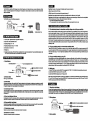
1.0 Foreword
The WK·G007 is utilized the AVes (Angular Vector Control System) and is of high performance, compact dimension and light
weight. It Is specially designed for the RC helicopter. The Integration of sensor section and control circuit makes the InstallaUon
easy and convenient.
2.0 Kit Contents
The WK-G007 comes with the following accessories:
• ro
Mini Screwdriver
emr Adjustments)
3.0 WK-G007 Technical Features
3.1 Control system: Digital advanced PI (proportional integration)
3.2 Gyro senaor: Mini piezoelectric sensor
3.3 Operating voltage: DC 4 - fN
3.4 Oparating temparature ranga: - 40 - +85"C
3.5 Dimension: 30 X 30 X 23 mm
3.7 Functions: reverse switch, AVes on/ofT switch, sensitivity trimmar, sarvo travel adjustmanl Tha gyro sansiliYily adjuslmant, and
AVCS mode & normal mode switch can be operated via the transmitler.
4.1 Idantifications
,----~. Gyro
LED -n~
.--t''::'::::'t='':;::J
4.2 Rewrse switch
Slow flash: Ihe gyro doeen'! receive the signal from the transmitter and the rudder servo Is out of control.
Fluh twiCII: in the AVes mode, the neulral position of the rudder servo current received signal is difrerent from the neutral position
which is previously saved in the gyro. Below are the situations of lIash twice:
a. The rudder servo bellaank is being adjusted;
b. The neutral pO$il:ion of the rudder servo has been drifted, and the neulral position h.. to be re.et.
6.0 Gyro Sensitivity Setting Via Transmitter
6.11he relationship between the b'ansmitler sensitivity setting value and the gyro sensitivity
When the receiver sensitivity channel sends the signal of neutral position, the gyro sensitivity value is O. When the signal sent is
above the neutral position, the gyro is in the AVes mode; whan the signal &ant is below Ihe neutral position, the gyro is in the normal
mode. If the transmitter, such as the WALKERA WK·1OO1, Is of gyro eensltlvlty adjustment function, Ihe gyro sensitivity can be adjusted
via the GYRO function In the transmitter; If the value Is set at 50%, the gyro sensitivity Is O. If the value Is set at 0 - 50%, the gyro
sensilivily is ranged from 100% to 0% (normal mode); iflhe value is setal50-1oo%, the gyro sensitivity is ranged from 0 to 100%
(Aves mode). The transmitter sensitivity switch can simultaneously control over the gyro sensitivity and operation moda. The ATV
value aI' the transmitter aanslUvity switch can alao take control aI' the gyro eensitlvlty. When the ATV Is at 90%, for example, the gyro
senslllYlly Is 100%.
Reverse switch
Take the WALKERA WK·1001 transmitter as an example. In tha Function Manu, salact the MODEL and access by pnissing the ENT
key, and then saled the GYRO and access via pressing the ENT kay again. Respectively set the normal flight mode (sensitivity at
75% for the Aves mode), ST·1 and ST·2 IIlght modes (sensitivity at 40% for the normal mode). SWitch the gyro sensitivity using the
mode awiIch.
8.3 Tha gyro Hnaitivity aatting by uaing ATV
4.0 WK-G007ldentifications and Functions
OS moda switch
LED orr: the gyro Is In the normal model or the power Is turned ofT.
8.2 Tha gyro Hnaltlvlty aattlng via tha tranamlttar aanaltMty switch
3.6 Weight: 27g
Control delay trimmer
Quick ftuh: the gyro is in the prooass of initialization when the power is tumed on.
LED on: the gyro Is In the AVCS mode.
travel adjustment trimmer
.........,. . . Gyro sensitivity Input connector
fF~~~b~• • Rudder Input connector
••
O§-~~~"'
Rudder servo connector
Aller the gyro control direction.
If the transmitter Is not of the gyro sensitivity setting function, choose an actlvlly switch, which Is awIIchable, In the transmitter (e.g.:
GEAR! INVERT switch in Ihe WALKERA WK-1oo1) and adjust the gyro sensilivityvia AT\! tetling mode. In the example al'WALKERA
WK-1001, enter the TRVADJ function item and respacliYaly the ATV of the GEAR as normal flight mode (sensitivity at 75% for
AVCS mode, the switch Is switched forward), ST·1 and ST-2 night modes (sensitivity at 40% for the normal mode, the switch Is
switched backward). Alterthe gyro sensitivity by switching the GEAR I INVERT switch.
8.4 Sattlng atap
1. Enter the TRVADJ menu to set the GEARATV by pressing the EXTI ENT, UP or ON (Rsfer to the InInsmltter user's manual).
2. SWitch GEAR/INVERT forward to 1181: ATV value at 75%.
3. SWitch GEAR/INVERT backward ID set ATV value at 40%.
Nota: while using the GEAR/INVERT to switch the gyro sensitivity, it is impossible to simultaneously sat the normal night mode,
ST·1 and ST·2 as AVes mode. One end of the GEAR/INVERT Is normal mode, and the other end Is the AVes mode. The GEAR!
INVERT should be set as NORM In the REVERS function.
4.3 AVCS awltch
Digital servo model switch. When the OS ONIOFF switch is switched to the ON position, the digital servo is activated; when the OS
ONIOFF switch Is switched to the OFF poelUon, the tradlUonal servo Is activated. Note: If the OS ONIOFF switch Is switched to the
ON position, damage or bum maybe happen on the low watt servo.
7.0 Use Method
4.4 Control dalay trimmar
Be careful when operating the switch and trimmer, because a small switch and trimmer ara used. Always operate the switch and
trimmer with the mini aaewdriver supplied. When mounting the WK·GOO7 gyro to the helicopter gyro bed, please use the double
adhesive tape with the WK-G007. At tna same time, please check the bottom of the gyro body Is perpendicular to the main shaft of
your helicopter. When used with a motor helicopter, mount the WK-G007 at least 10 em away from the drive motor.
The control delay trimmer Is used to adjust the signal speed. If a slO'lo'4peed servo Is used and found the hunting effect, clockwise
tunes the trimmer andlncreaees the delay Ume to eliminate the e1'Ject. If a hlgh....peed aarvo, such as a digital eervo, Is uaad, adjust
the trimmer to O.
4.5 Gyro travel adJuatmant trimmer
Set the maximum travel of the rudder servo. Pull the rudder stick to the fullllJll and right ends raspactivaly and adjust the rudder servo
travel within the maximum ranges of the tail rotor sleeve. Clockwi.e tuning Ihe trimmer increnes the rudder travel.
7.1 Mounting to tha fusel.ga
7.2 Wiring diagram
4.6 Gyro Hnsllvlty Input trimmer
r - • • Co"",""", 10 the raoaiver sensitivity input oonnector
Connects to the receiver senslllYlty Input channel (usually AUX 2 or AUX 3). Thelr1mmer can be used ID switch the gyro senslllYlly
and mode (AVCS moda and normal mode). Single oore is easy to be broken and is forbidden to draw.
4.7 Ruddar Input connactor
Rudder input connector connects to the rudder input channel of the receiver.
4.8 Ruddar HrvO connactor
Rudder servo connector connacls to the rudder salVO.
7.3 Servo Hlactlon
While UIIing the digital servo as the rudder servo, switch the OS ON/OFF switch to the ON position. \/\/hile using the traditional servo
as the rudder Hrvo, switch the OS ONI OFF switch to the OFF position. Not.: when using a traditional Mrvo and switching the OS
ONI OFF switch to the ON position, damage or even bum may happen on the low watt servo.
7.4 InspKt. the rudder bellcrank
Switch the gyro AVCS switch to the normal mode. Tum on the transmitter power and then tum on the receiver power. Don' move
ttw HrYO bIIIlcrank or ttw h-'ioopler for about 3 MOOI"Ids blK:aUM the WK-G007 gyro is initializing. LED will int.rmil:lently flash. \/\/h.., ttw
rudder servo is in neutral position, it must be linked at e position to which the servo bellCl"lllnk and servo push rod are perpendicular.
Adjust thelangih ofttw rudder 118M) ballcrank In accordance with the heilcoplBr manual. Try moving the rudder sUck to ttw left and righi,
and chllCk ttw direction of the rudder Mrvo oPliration. If the rudd.- Hrvo movn in the opposit8 direction, use tt. transmitlBr I'W'MIH
function to reverse it
Not.: if tt. rudder r.volution mixing function is activated, put the throttle slick at the neulral position wtwn setting tt. neutral position
at initialization. For the safety purpose, when setting the motor, tum off the motor power or awiIch off the rudder revolution mixing
funcUon, and set the value to zero.
7,5 Gyro sensitivity adjustment
The gyro Mnsitivity depends on the rudder Mrvo and heliooptar. In principle, the fastar the rudd.- HIVO spHd is, the high.- the
gyro sensitivity has to be set. The faster the main rotor blade rotation is, the higher the rudder servo sensitivity has to be inaeased.
So adjusting the gyro senslUvity Is a must. For example, the sensllMly for the aerobatlc maneuvers (ST-1, ST-2) must be lower than
that at hOVllring flight. Set the gyro sensitivity bimmer to the approximalBly SO - 70% for aerobatic maneuver, and 70 - 80% for
hovering lIight
7,6 Inspection of the gyro operation direction
Lift off and hover the helicopter, and shake the helicopter head leftward. The drift dlredlon of the rudder servo should be same
with the rudder stick of the transmitter, which moves rightward. otherwiHl, reverse the reverse switch in the gyro. Nota: if
setting the gyro operation direction wrong, the helicopter will auto rotate at high speed and result in .erious danger!
7.7 Adjustment of rudder Hrvo tl'O".1
Pull the rudder stick to the full left and right ends respectively and adjust the rudder servo travel within the maximum ranges of the
tall rotor sleeve. During 1I1ght, the rudder servo movement Is within the maximum travel and protect the servo and Its bellc:rank. Don't
set the rudder sarvo travel too narrow to decrease the gyro performance.
7.8 Flying adjustment
In the AVes mode, the WK-GOO7 automatically sets the rudder neutral position and stope any IIlIII drift. For the first flight or correcting
the bellcrank, tum off the AVCS function and adjust the mechanical neutral position. AVes mode is recommended during flight.
7.9 Rudder neutral adjustment
1. Tum off the transmitter I'8'JOlulion mixing or set the transmitter I'8'JOlution mbdng (pitch or rudder) 10 0%.
2. Switch the transmitter sensilivily switch to the normal mode. Tum on the transmitter power and receiver power in sequer1f::e. Don'
move the hellcopterfcr approxfmately three seconds because the WK-G007lnlllatea the data when the power Is turned on.
3. un off and hover the helicopter, and fieri adjust the rudder neulr1ll position with the transmitter bim.
4. Gradually adjust the gyro aansitivity just before the helicopter tail starts Ie hunt.
Nota: after the neutral setting Is finished, don't adjust the rudder b"lm again. Otherwise, the neutral poslUon has to be re-adjusted.
7.10 Lock mode adjustment
1. SWItch the flight mode. Alter the 'flIght, observe the LED. LED on means normal; LED flash twice means the neutral position has
been drllted and need to be reeat.
2. Hover the helicopter and adjust the gyro sensnlvlty to just before the helicopter begins to hunt. In principle, the gyro sensKlvlty In
the Aves mode Is lees then that In the normal mode.
3. Adjust the transmitter dual rate (DJR) to accord with your hand feeling.
4. Control the high-speed auto rotation via adjusting the helicopter rudder servo. \/\/hen the helK:oPter stops auto rotation and begins
to hunt, increase the delay trimmer. Low-speed servo will easily hunt. Don't adjust the delay trimmer at a big rate. Otherwise, the
rudder servo will drift and Its reaction will be slaw. \/\/hen a high-speed servo Is used, set the delay b"lmmer to 0 position.
S. With an AVes gyro, when the helicopter encounllllrs a cross-wlnd and the trail drifts, a control signal from the gyro stops the drift.
N. th. sarne time, the gyro oompu18s the drift angle and oonstllntly outputs a oontrol signal that resists the cross-wind. Therefore,
drifting of the tail can be stopped even if the crou-wind continues to affect the helicopter. The gyro itself automatically corrects
changes In helicopter tall trim by cross-wind.
Nota: alter the neutral setting Is finished, don't adjust the rudder b"lm again. Otherwise, the neutral poslUon has to be re-adjusted.