1
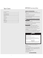
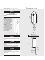
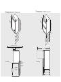
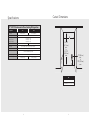
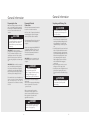
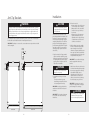
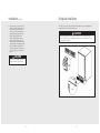
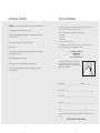
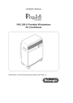
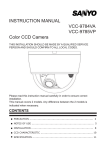
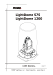
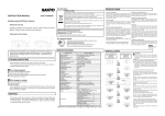
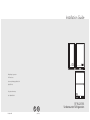
Installation Guide
Viking Range Corporation
111 Front Street
Greenwood, Mississippi 38930 USA
(662) 455-1200
For product information,
call 1-888-845-4641
UL
F20868A EN
C
UL
(020113)
15”W./24”W.
Undercounter Refrigeration
IMPORTANT–Please Read and Follow!
Table of Contents
Warnings & Important Information____________________________________________________________3
Proper Disposal ______________________________________________________________________________4
Dimensions (15”W. Professional) ______________________________________________________________5
Dimensions (24”W. Professional) ______________________________________________________________6
Dimensions (24”W. Professional) ______________________________________________________________7
Specifications ________________________________________________________________________________8
Cutout Dimensions ___________________________________________________________________________9
General Information_________________________________________________________________________10
Anti-Tip Brackets ____________________________________________________________________________12
Installation __________________________________________________________________________________13
Kickplate Installation ________________________________________________________________________15
Installation Checklist ________________________________________________________________________16
Service Information _________________________________________________________________________17
IMPORTANT – PLEASE READ AND FOLLOW
• Before beginning, please read these instructions completely and carefully.
• DO NOT remove permanently affixed labels, warnings, or plates from the product. This may
void the warranty.
• Please observe all local and national codes and ordinances.
• Please ensure that this product is properly grounded.
• The installer should leave these instructions with the consumer who should retain for local
inspector’s use and for future reference.
A GFI shall be used if required by NFPA-70 (National Electric Code), federal/state/local
laws, or local ordinances.
• The required use of a GFI is normally related to the location of a receptacle with respect to
any significant sources of water or moisture.
• Viking Range Corporation will NOT warranty any problems resulting from GFI outlets which
are not installed properly or do not meet the requirements below.
If
•
•
•
•
the use of a GFI is required, it should be:
Of the receptacle type (breaker type or portable type NOT recommended)
Used with permanent wiring only (temporary or portable wiring NOT recommended)
On a dedicated circuit (no other receptacles, switches or loads in the circuit)
Connected to a standard breaker of appropriate size (GFI breaker of the same size NOT
recommended)
• Rated for Class A (5 mA +/- 1 mA trip current) as per UL 943 standard)
• In good condition and free from any loose-fitting gaskets (if applicable in outdoor situations)
• Protected from moisture (water, steam, high humidity) as much as reasonably possible.
WARNING
To reduce the risk of fire, electric shock, or injury when using your unit, follow these basic precautions:
• Read all instructions before using the unit.
• Never allow children to operate, play with, or crawl inside the unit.
• Never clean unit parts with flammable fluids. The fumes can create a fire hazard or explosion.
• Always turn the power on/off switch (located behind the air grille on top right side) to the OFF position
before attempting to change light bulbs, clean, or service the unit.
FOR YOUR SAFETY
DO NOT STORE OR USE GASOLINE OR OTHER FLAMMABLE VAPORS AND LIQUIDS IN THE VICINITY OF
THIS OR ANY OTHER APPLIANCE. THE FUMES CAN CREATE A FIRE HAZARD OR EXPLOSION.
It is your responsibility to be sure your undercounter refrigeration is:
• located so the front is not blocked to restrict incoming or discharge air flow.
• properly leveled.
• located in a well ventilated area.
• connected to the proper kind of outlet, with the correct electric supply and grounding. A
115V, 60 Hz, 15 amp fused electrical supply is required. Note: Time delay fuse or circuit
breaker is recommended.
• not used by anyone unable to operate it properly.
• used only for its intended purpose.
• properly maintained.
•SAVE THESE INSTRUCTIONS•
2
3
Proper Disposal
(of old refrigeration unit)
Dimensions
DANGER
14
(37-7/8
”
.8
c
RISK OF CHILD ENTRAPMENT
Before You Throw Away Your Old Refrigeration Unit:
• Take off the doors.
• Leave the shelves in place so that children may not easily climb inside.
(15”W. Professional)
m)
34
30
-1
(76
.5
IMPORTANT: Child entrapment and suffocation are
not problems of the past. Junked or abandoned
refrigeration units are still dangerous—even if they
will sit for “just a few days”. If you are getting rid of
your old refrigeration unit, please follow these
instructions to help prevent accidents.
(87-1/4
.0 ”
mi cm)
n.
to
3
(89 5”
.0
ma cm)
x.
/8”
cm
)
”
/16)
1
m
226.0 c
(5
”
16)
/
1
241.1 cm
(6
”
/16)
9
26 .5 cm
IMPORTANT: Now that you have a new refrigeration
unit, it is extremely important that you dispose of
your old appliance in a way that minimizes the
possibility that children will find it. There have been
many cases in years past of children crawling inside
junked and abandoned refrigeration units and
becoming trapped or suffocated.
(67
Contact your municipal waste disposal authority to
find out the best and safest way to dispose of your old
refrigeration unit.
50” (127.0 cm) area in which
electrical outlet must be located
DANGER
Power cord 6-5/8”
(16.8 cm) off floor.*
5-1/16”
(12.9 cm)
Altering, cutting of the power cord, or removal of the power cord, removal of power plug, or
direct wiring can cause serious injury, fire and/or loss of property and/or life and will void the
warranty.
WARNING
• Never attempt to repair or perform maintenance on the unit until the electricity has been
disconnected.
• The anti-tip kit must be installed on this unit before it is used. Never use the drawers,
shelves or doors as steps or to support more than they were designed to support.
Door Swing
CAUTION
• Do not lift unit by drawer or door handles.
• Failure to clean the condenser every three months can cause the unit to malfunction. This
could void the warranty.
• Never install the unit behind closed doors. Be sure front louvered kickplate is free of
obstruction. Obstructing free airflow can cause unit to malfunction, and may void warranty.
4
15-25/32”
(40.1 cm)
min. clearance
for door swing
94.0° Swing
required for
pull-out shelf
clearance
5
2-3/16”
(5.6 cm) min.
clearance
from a corner
to achieve 94°
door swing
Dimensions
Dimensions
(24”W. Professional)
(24”W. Professional)
23
23
(60-7/8
.6 ”
c
(60-7/8
.6 ”
cm
)
m)
30
(76-1/8
.5 ”
cm
)
30
(76-1/8
.5 ”
cm
)
34
(87-1/4
.0 ”
mi cm)
n.
to
35
(89 ”
.0
ma cm)
x.
34
(87-1/4
.0 ”
mi cm)
n
to .
3
(89 5”
.0
ma cm)
x.
”
/16)
1
2 cm
/6”)
1
2 cm
2 6.0
5
(
2 .0
”
16
-1/ )
(56
”
/16)
1
m
4 c
241.1 cm
(6
”
16
-9/cm)
6
2 7.5
2 1.1
6
(
”
/16)
9
m
6 c
2 7.5
6
(6
(
50” (127.0 cm) area in which
electrical outlet must be located
7-9/16”
(12.9 cm)
40” (102.0 cm)
Power cord 6-7/16”
(16.8 cm) off floor.*
2-27/32”
(5.6 cm) min.
clearance
from a corner
to achieve 94°
door swing
Door Swing
24-25/32”
(40.1 cm)
min. clearance
for door swing
94.0° Swing
required for
pull-out shelf
clearance
Door Swing
22-1/16” (56.0 cm)
24-1/16” (61.1 cm)
26-9/16” (67.5 cm)
6
7
Cutout Dimensions
Specifications
15”/24”W. Undercounter/Freestanding Refrigeration
Description
Overall width
Overall height
15”
24”
14-7/8” (37.8 cm)
23-7/8” (60.6 cm)
34-1/4” (87.0 cm) min. to 35” (89.0 cm) max.
Overall depth from rear cabinet
(with door panel)
(with door handle)
Cutout width
15” (38.1 cm)
24” (61.0 cm)
Cutout height
34-1/2” (87.6 cm) min. to 35-1/2” (90.2 cm) max.
Cutout depth
24” (61.0 cm)
Electrical requirements
115V/60 Hz, 15 amp dedicated circuit
5’ 3-wire cord attached to product
Maximum amp usage
3.0 amps
Approximate shipping weight
A
22-1/16” (56.0 cm)
24-1/16” (61.1 cm)
26-9/16” (67.5 cm)
175 lbs. (79.0 kg)
” )
24 cm
.0
1
6
215 lbs. (98.0 kg)
34-1/2”
(87.6 cm)
min.
to
35-1/2”
(90.2 cm)
max.
4” (10.2 cm)
min.
to
10” (25.4 cm)
max.
(
A
15”W. Models - 15” (38.1 cm)
24”W. Models - 24” (61.0 cm)
8
9
General Information
General Information
Preparing the Area
Preparing Electrical
Connections
Make sure that the opening area where the
unit is to be installed is properly prepared.
Ensure the space dimensions and electrical
service are correct for the models to be
installed.
All electrical instructions assume that outlet is
located 4 to 10 inches from the floor.
A 115 volt, 60Hz, 15 amp circuit breaker and
electrical supply are required. A separate
circuit is required for each unit installed.
CAUTION
If unit is being installed under a countertop,
it is recommended that the countertop be
supported by structure other than the
refrigerated cabinet to prevent damage to
the countertop.
Follow the National Electrical Code and local
codes and ordinances when installing the
receptacle.
All units come equipped with a NEMA 5-15P
90° plug with a minimum of 5-feet of cord
extending beyond the rear of the cabinet.
The electrical outlet must be flush with or
recessed into the back wall.
IMPORTANT: For a door to operate
properly, the door must open a minimum of
94°. Use a minimum 3-inch filler in corner
installations to assure a 94° door opening.
Allow 24” clearance in front of the unit for
full door swing, shelf pull-out or drawer pullout.
IMPORTANT: Never use an extension cord
to extend the power cord to the electrical
receptacle.
IMPORTANT: Make sure the floor under the
unit is level with the surrounding finished
floor. Protect a finished floor with plywood,
cardboard or some other suitable material
before moving the unit into place. Failure to
do this may result in damage to the floor.
DANGER
ELECTROCUTION HAZARD
Electrical grounding required. This
appliance is equipped with a three prong
(grounding) polarized plug for your
protection against possible shock hazards.
Floor must be level in area of installation. Leg
levelers are used for fine-tune adjustment
only and should not be be used to
compensate for floor differences exceeding
1/2 inch.
Never remove the round grounding prong
from the plug.
• Never use a two-prong grounding adapter.
• Never use extension cord to connect
power to the unit.
Unpacking and Moving Unit
CAUTION
Do not cut cardboard sleeve covering the
unit. Cutting may result in damage to the
exterior of the cabinet.
1. Uncrate the unit outside on a flat level
surface. Remove the cardboard sleeve by
removing the banding holding the sleeve
to the shipping base. Carefully lift the
cardboard sleeve up over the top of the
unit.
2. Carefully lift unit off base and onto a hand
truck or dolly (this should be done with a
minimum of two people; larger units may
require additional help). Make sure unit is
balanced on transporting device. Secure
unit to transporting device using soft,
flexible strapping. Protect unit surfaces
with cloth material where strapping
contacts unit.
3. Before moving unit, secure door to unit
with tape so the door stays closed.
4. Carefully move unit to installation site and
place in front of opening. Take care to
protect floor surface with cardboard, rugs,
etc.
WARNING
A minimum of two people should lift the
unit at the base to prevent possible
personal injury.
Where a two-prong wall receptacle is
encountered or a longer power cord is
required, contact a qualified electrician to
have it replaced in accordance with
applicable electrical codes.
DANGER
Failure to comply with the above electrical
guidelines may result in possible injury,
death, fire or loss of property.
10
11
Installation
Anti-Tip Brackets
WARNING
Unit may tip forward if loaded racks/shelves are all pulled out at the same time. To prevent
tipping and provide a stable installation, the unit must be secured in place with the anti-tip
brackets provided with the unit. A set of metal anti-tip brackets are supplied with the unit.
The anti-tip brackets, when properly installed should secure the rear legs and prevent the
unit from tipping forward.
Some installation sites may require modification to provide a secure surface for attaching the
brackets. Refer to the illustrations below for mounting bracket locations.
IMPORTANT: If installing on a concrete floor, concrete fasteners are required and not included
with the anti-tip kit.
Anti-tip
Bracket
ø 3/8”
(1.0 cm)
15/16”
(2.4 cm)
13-1/2”
(34.3 cm)
3/16”
(0.5 cm)
22-1/32”
(56.0 cm)
15/16”
(2.4 cm)
3. If all surfaces are level:
a. Measure from the floor to the bottom
of the front edge of the countertop
b. Measure the rear of the unit cabinet
from the floor to top of cabinet, at
back corners
c. Adjust rear legs so B measurement
equals A measurement. Using an
adjustable wrench or pliers, turn legs
counterclockwise to raise the unit or
clockwise to lower the unit
CAUTION
Any finished flooring should be protected
with appropriate material to avoid damage
from moving the unit.
If unit has been laid on its back or sides,
place unit upright and allow minimum of 24
hours before connecting power.Re-installl
the doors by removing the upper pivot pin
completely, sliding the door onto the lower
pivot pin and re-installing the upper pivot
pin and fastening tightly. Before moving the
unit, make sure the door is secured to the
cabinet (tape may be required to hold the
doors closed).
4. Slide the cabinet into position, making
sure the rear cabinet leveling legs slide
under the anti-tip devices. Push the
cabinet into the opening until the bottom
front edge of the cabinet is flush with the
surrounding cabinetry or the leveling legs
are tight with the anti-tip devices.
1. Plug the unit into the 15 amp grounded
outlet located in the installation opening.
With power applied to the unit, check that
the lighting and cooling function operate
properly, then turn off power to the wall
outlet at the circuit breaker.
IMPORTANT: The rear cabinet leveling legs
must be engaged under the anti-tip
brackets.
WARNING
3/16”
(0.5 cm)
5. Shim the front of the unit so the front face
is flush with surrounding cabinetry. Adjust
the front legs to support the countertop
at the shimmed height. Using an
adjustable wrench or pliers, turn legs
counterclockwise to raise the unit or
clockwise to lower the unit. Countertop
should be resting on top of the unit.
Shut off power to the wall outlet before
installing into the opening.
2. Check that the following are level and
square:
• Front face and interior opening
• Installation opening and floor surface
• Countertop bottom front edge
IMPORTANT: If countertop is not resting
entirely on unit top, shim the countertop to
prevent damage to the countertop.
IMPORTANT: Leveling legs should not be
extended more than 3/4” from bottom of
the cabinet.
CAUTION
To prevent damage to the countertop and
unit underneath, do not place heavy
objects on countertop directly above the
unit.
IMPORTANT: The floor under the unit must
be at the same level as the surrounding
finished floor.
FRONT OF UNIT
FRONT OF UNIT
12
13
Installation
Kickplate Installation
(cont.)
6. Check interior door openings inside the
cabinet to ensure the cabinet is level. Reinstall all shelving and drawers. Take
extreme care to insert sliding shelving
and sliding drawers squarely into slide
brackets and proper slide bracket
grooves. When sliding shelving and
drawers are installed properly a click
should be heard from both slide bracket
retaining clips and should slide smoothly
in the tracks. When sliding shelving or
drawers are pulled out to full extension, a
stop is activated to prevent additional
pull-out.
When the unit is secured in place, install the slotted kickplate. Secure slotted kickplate by
snapping the latch into the latch catch on the unit.
CAUTION
The slotted kickplate must be removable for servicing. The floor cannot interfere with
removal. The slotted sections of the kickplate must not be covered or obstructed so as to
prevent proper air circulation.
CAUTION
Improper shelving or drawer installation
may not actuate slide stop mechanism.
14
15
Installation Checklist
IMPORTANT: To ensure a safe and proper installation, review below items directly with installer.
h Has all shipping tape, string and packing been removed?
h Has the unit been secured in place with the provided anti-tip bracket or is the unit 1 inch or
less from a solid soffit?
h Are all levelers extended down to make contact with the floor?
Service Information
If service is required, call your dealer or authorized service agency. The name of the authorized service
agency can be obtained from the dealer or distributor in your area.
When you make a service call, be sure to have the following information handy:
• Model Number
• Serial Number
• Date of Purchase
• Name of dealer from whom purchased
If you are unable to obtain the name of an authorized service agency, or if you continue to have service
problems, contact Viking Range Corporation at (888) 845-4641 or write to:
h Is the unit level?
h Is the power cord connected directly into a properly grounded 3-prong outlet in accordance
with all applicable local codes?
h Has all stainless protection film been removed?
h Are the panel(s) (wood overlays, if used) attached securely and properly?
h Allow the unit to operate for at least 24 hours before loading products or adjusting
temperature settings.
VIKING RANGE CORPORATION
PREFERRED SERVICE
1803 Hwy 82W
Greenwood, Mississippi 38930 USA
Record the information indicated below. You will need it if
service is ever required. The model and serial number for
your undercounter refrigeration unit are located in the top
right under the control housing.
Model and
Serial number
Model Number ____________________________________Serial Number _______________________
Date of Purchase _______________________________________________________________________
Date Installed __________________________________________________________________________
Dealer’s Name _________________________________________________________________________
Address _______________________________________________________________________________
If service requires installation of parts, use only authorized parts to insure protection under the
warranty.
KEEP THIS MANUAL FOR FUTURE REFERENCE.
16
17
18
19