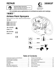
1
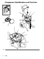
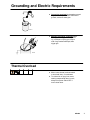
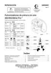
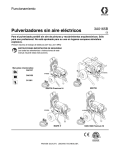
Repair Instructions and Parts List
309423M
Parts
- For portable spray application of architectural paints and coatings -
1900 Plust Airless Paint Sprayer
3000 psi (207 bar, 20.7 MPa) Maximum Working Pressure
Important Safety Instructions
Read all warnings and instructions in this manual.
Save these instructions.
. . . . . . . 309427
. . . . . . . 309971
. . . . . . . 309428
Model 233782 (Series A, B)
Model 246649 (Series A, B, C, D)
. . . . . . . 311062
Model 233782 (Series C, D, E, F)
ti8027a
ti7508a
Hi-Boy 233782
Series A, B, C, D, E, F
Stand 246649
Series A, B, C, D
Specifications
This equipment is not intended for use with flammable or combustible materials used in places such as
cabinet shops or other “factory” or fixed locations. If you intend to use this equipment in this type of
application, you must comply with NFPA 33 and OSHA requirements for the use of flammable and
combustible materials.
Warnings
The following Warnings are for the safe setup, use, grounding, maintenance and repair of this equipment. The
exclamation point symbol alerts you to a general warning and the hazard symbols refer to procedure--specific risks.
Refer back to these Warnings. Additional, product--specific warnings may be found throughout the body of this
manual where applicable.
WARNING
FIRE AND EXPLOSION HAZARD
Flammable fumes, such as solvent and paint fumes, in work area can ignite or explode. To help
prevent fire and explosion:
D Use equipment only in well ventilated area.
D Sprayer generates sparks. When flammable liquid is used in or near sprayer for flushing or cleaning, keep sprayer at least 20 feet (6 m) away from explosive vapors.
D Do not clean with materials having flash points lower than 70_F (21_C). Use water--based materials or mineral spirit--type material only. For complete information about your fluid, request the
MSDS from the fluid distributor or retailer.
D Eliminate all ignition sources; such as pilot lights, cigarettes, portable electric lamps, and plastic
drop clothes (potential static arc).
D Keep work area free of debris, including solvent, rags and gasoline.
D Do not plug or unplug power cords or turn lights on or off when flammable fumes are present.
D Ground equipment and conductive objects in work area. Read Grounding instructions.
D Use grounded hoses.
D Hold gun firmly to side of grounded pail when triggering into pail.
D If there is static sparking or you feel a shock, stop operating immediately. Do not use equipment
until you identify and correct the problem.
D Keep a fire extinguisher in the work area.
SKIN INJECTION HAZARD
High pressure fluid from gun, hose leaks, or ruptured components will pierce skin. This may look like
just a cut, but it is a serious injury that can result in amputation. Get immediate surgical treatment.
D Do not point gun at anyone or any part of the body.
D Do not put your hand over the spray tip.
D Do not stop or deflect leaks with your hand, body, glove, or rag.
D Do not spray without tip guard and trigger guard installed.
D Engage trigger lock when not spraying.
D Follow Pressure Relief Procedure in this manual, when you stop spraying and before cleaning,
checking or servicing equipment.
2
309423
WARNING
ELECTRIC SHOCK HAZARD
Improper grounding, setup, or usage of the system can cause electric shock.
D Turn off and disconnect power cord before servicing equipment.
D Use only grounded electrical outlets
D Use only 3--wire extension cords.
D Ensure ground prongs are intact on sprayer and extension cords.
D Do not expose sprayer to rain. Store indoors.
EQUIPMENT MISUSE HAZARD
Misuse can cause death or serious injury.
INSTRUCTIONS
D Do not operate the unit when fatigued or under the influence of drugs or alcohol.
D Do not exceed the maximum working pressure or temperature rating of the lowest rated system
component. See Technical Data in all equipment manuals.
D Use fluids and solvents that are compatible with equipment wetted parts. See Technical Data in
all equipment manuals. Read fluid and solvent manufacturer’s warnings. For complete information
about your material, request MSDS from the fluid distributor or retailer.
D Check equipment daily. Repair or replace worn or damaged parts immediately with genuine
manufacturer’s replacement parts only.
D Do not alter or modify equipment.
D Use equipment only for its intended purpose. Call your distributor for information.
D Route hoses and cables away from traffic areas, sharp edges, moving parts and hot surfaces.
D Do not kink or over bend hoses or use hoses to pull equipment.
D Keep children and animals away from work area.
D Comply with all applicable safety regulations.
PRESSURIZED ALUMINUM PARTS HAZARD
Do not use 1,1,1-trichloroethane, methylene chloride, other halogenated hydrocarbon solvents or
fluids containing such solvents in this equipment. Such use could result in a serious chemical reaction,
with the possibility of explosion, which could cause death, serious injury and/or substantial property
damage.
TOXIC FLUID HAZARD
Toxic fluid or fumes can cause serious injury or death if splashed in the eyes or on skin, inhaled, or
swallowed.
D Read MSDS’s to know the specific hazards of the fluids you are using.
D Store hazardous fluid in approved containers and dispose of it according to all applicable guidelines.
PERSONAL PROTECTIVE EQUIPMENT
You must wear appropriate protective equipment when operating, servicing, or when in the operating
area of the equipment to help protect you from serious injury, including eye injury, inhalation of toxic
fumes, burns, and hearing loss. This equipment includes, but is not limited to:
D Protective eye wear.
D Clothing and respirator as recommended by the fluid and solvent manufacturer.
D Gloves.
D Hearing protection.
309423
3
Component Identification and Function
T
A
J
H
R
B
P S
K
D
F
N
G
E
M
H
U
ti6013b
A
V
B
U
J
T
K
F
D
ti5875b
E
Fig. 1
4
309423
G
V
Component Identification and Function
A
Motor
DC motor, permanent magnet, fan cooled
B
Drive Assembly
Transfers power from DC motor to displacement pump
D
Displacement Pump
Transfers fluid to be sprayed from source through spray gun
E
Fluid Outlet
Spray gun is connected here
F
Prime Valve
Used to prime and drain sprayer (also relieves fluid outlet pressure) when
open
G
Fluid Filter (optional)
Final filter of fluid to spray gun
H
Pressure Adjusting Knob
Controls fluid outlet pressure
J
Pressure Control
Controls motor speed to maintain fluid outlet pressure at displacement pump
outlet. Works with pressure adjusting knob.
K
ON/OFF Switch
Power switch that controls main power to sprayer
M
50 ft (15 m) Main Hose
1/4 in. ID, grounded, nylon hose with spring guards on both ends
N
Spray Gun
High pressure spray gun with gun safety latch
P
Spray Tip
Uses high pressure fluid to clear tip clogs without removing tip from spray gun
R
Tip Guard
Tip guard reduces risk of injection injury
S
Thumb Lock Safety
Gun safety latch inhibits accidental triggering of spray gun
T
Power Cord Rack
Holds wrapped power cord for storage
U
Suction Hose
Transfers fluid to be sprayed from source to pump
V
Drain Tube
Fluid outlet used to drain and prime the sprayer
309423
5
Grounding and Electric Requirements
The sprayer must be grounded. Grounding reduces the risk of static
and electric shock by providing an escape wire for the electrical current due to static build up or in the event of a short circuit.
D The sprayer requires a 120V AC, 60 Hz, 15A
circuit with grounding receptacle. Never use
an outlet that is not grounded or an adapter.
ti3001b
D Do not use the sprayer if the electrical
cord has a damaged ground prong.
Only use a 3--wire extension cord with
an undamaged, 3--prong plug.
D Recommended extension cords for
use with this sprayer:
D
D
D
D
ti5572a
25 ft (7.6 m) 18 AWG
50 ft (15.2 m) 16 AWG
100 ft (30.5 m) 14 AWG
150 ft. (45.7 m) 12 AWG
Smaller gauge or longer extension cords
may reduce sprayer performance.
D Ground sprayer gun through connection to
a properly grounded fluid hose and pump.
D Ground fluid supply container.
Follow local code.
D Ground solvent pails used when flushing. Follow local code. Use only conductive, metal pails, placed on a grounded
surface such as concrete. Do not place the
pail on a non--conductive surface such as
paper or cardboard, which interrupts the
grounding continuity.
ti5850a
6
309423
Grounding and Electric Requirements
D Ground the metal pail by clamping one end
of ground wire to pail and the other end to
ground, such as a water pipe.
ti5851a
D Maintain grounding continuity when
flushing or relieving pressure by holding metal part of spray gun firmly to
side of a grounded metal pail, then
trigger gun.
ti6762a
Thermal Overload
D Motor has a thermal overload switch
to shut itself down if overheated.
D To reduce risk of injury from motor
starting unexpectedly when it cools,
always turn power switch OFF if
motor shuts down.
309423
7
Pressure Relief Procedure
Follow Pressure Relief Procedure when you
stop spraying and before cleaning, checking, servicing or transporting
equipment.
1. Turn power switch OFF and unplug power cord.
2. Turn Spray--Prime/Drain valve to PRIME/DRAIN to
relieve pressure.
PRIME
3. Turn pressure to lowest setting. Hold metal part of
gun firmly to a grounded metal pail. Trigger gun to
relieve pressure.
ti6762a
4. Engage trigger lock.
ti6763a
D Leave Spray--Prime/Drain valve in PRIME/DRAIN
position until you are ready to spray again.
PRIME
8
309423
D If you suspect the spray tip is clogged or that pressure
has not been fully relieved after following the above
steps, VERY SLOWLY loosen tip guard retaining nut
or hose end coupling to relieve pressure gradually.
Then loosen completely. Clear hose or tip obstruction.
General Repair Information
WARNING
WARNING
Flammable materials spilled on hot,
bare, motor could cause fire or
explosion. To reduce risk of burns, fire or
explosion, do not operate sprayer with
cover removed.
D Keep all screws, nuts, washers, gaskets, and
electrical fittings removed during repair procedures.
These parts usually are not provided with replacement kits.
D Test repairs after problems are corrected.
D If sprayer does not operate properly, review repair
procedure to verify you did it correctly. See Troubleshooting, page 10.
D Overspray may build up in the air passages. Remove any overspray and residue from air passages
and openings in the enclosures whenever you
service sprayer.
D Do not operate the sprayer without the motor
shroud in place. replace if damaged. Motor shroud
directs cooling air around motor to prevent overheating and insulate the control board from accidental electric shock.
To reduce risk of serious injury, including
electric shock:
D Do not touch moving or electric parts
with fingers or tools while testing repair
D Unplug sprayer when power is not
required for testing
D Install all covers, gaskets, screws and
washers before you operate sprayer
CAUTION
D Do not run sprayer dry for more than 30 seconds.
Doing so could damage pump packings.
D Protect the internal drive parts of this sprayer
from water. openings in the cover allow for air
cooling of the mechanical parts and electronics
inside. If water gets in these openings, sprayer
could malfunction or be permanently damaged.
D Prevent pump corrosion and damage from freezing. Never leave water or water--base paint in
sprayer when it is not in use in cold weather.
Freezing fluids can seriously damage sprayer.
Store sprayer with Pump armour to protect sprayer during storage.
D Do not operate the sprayer without the motor
shroud or control box cover in place. Replace if
damaged. Motor shroud directs cooling air around
motor to prevent overheating and the control box
cover insulates the control board from accidental
electric shock.
309423
9
Troubleshooting
Before performing any repairs, relieve pressure, page 8.
MOTOR WON’T OPERATE
TYPE OF PROBLEM
WHAT TO CHECK
If check is OK, go to next check
Basic Fluid Pressure
Problems
1. Pressure control knob setting. Motor will not run 1. Slowly increase pressure setting to see if moif at minimum setting (fully counterclockwise).
tor starts.
Basic Mechanical
Problems
WHAT TO DO
When check is not OK refer to this column
2. Spray tip or fluid filter may be clogged.
2. Relieve pressure and clear clog or clean filter; refer to separate gun or tip instruction
manual.
1. Pump (13) frozen or hardened paint.
1. Thaw sprayer if water or water-based paint
has frozen in sprayer. Place sprayer in warm
area to thaw. Do not start sprayer until
thawed completely. If paint hardened (dried)
in sprayer, replace pump packings. See
page 26 (Displacement Pump Replacement).
2. Displacement pump connecting rod pin (9a). 2. Push pin into place and secure with spring rePin must be completely pushed into connecting
tainer.
rod (9) and retaining spring (9b) must be firmly
in groove of pump pin. See Fig. 11.
3. Motor (1). Remove drive housing assembly 3. Replace motor (1) if fan won’t turn. See page
(10). See page 24. Try to rotate fan by hand.
25.
10
309423
1. Motor control board. Board shuts down and dis- 1. See Motor Control Board Diagnostics,
Basic Electrical Problems
plays error code on some models.
page 19.
See Wiring
page
g Diagram,
g
,p
g
17.
2. Electrical supply. Meter must read 100--130
2. Reset building circuit breaker; replace buildVAC for 110--120 VAC models and 210--255
ing fuses. Try another outlet.
VAC for 240 VAC models.
3. Extension cord. Check extension cord continu- 3. Replace extension cord.
ity with volt meter.
4. Sprayer power supply cord. Inspect for damage 4. Replace power supply cord.
such as broken insulation or wires.
5. Fuse. Check replaceable fuse on control board. 5. Replace fuse after motor inspection.
6. Motor leads are securely fastened and properly 6. Replace loose terminals; crimp to leads. Be
connected to control board.
sure terminals are firmly connected.
Clean circuit board terminals. Securely reconnect leads.
7. Motor thermal switch. Yellow motor leads must 7. Replace motor. See page 25, Motor Rehave continuity through thermal switch.
placement.
8. Brush cap missing or loose brush lead connec- 8. Install brush cap or replace brushes if leads
tions.
are damaged. See page 14, Motor Brush Replacement.
9. Brush length which must be 1/4 in. (6 mm) mini- 9. Replace brushes. See page 14, Motor Brush
mum.
Replacement.
NOTE: Brushes do not wear at the same rate on
both sides of motor. Check both brushes.
10.Motor armature commutator for burn spots, 10. Remove motor and have motor shop resurgouges and extreme roughness.
face commutator if possible. See page 25,
Motor Replacement.
11. Motor armature for shorts using armature tester 11. Replace motor. See page 25, Motor Re(growler) or perform spin test, page 14.
placement.
12.Pressure control not plugged in to control board. 12.Insert pressure control connector into control
board.
309423
11
Troubleshooting
LOW OR FLUCTUATING OUTPUT
TYPE OF PROBLEM
WHAT TO CHECK
If check is OK, go to next check
WHAT TO DO
When check is not OK refer to this column
Low Output
1. For worn spray tip.
1. Follow Pressure Relief Procedure Warning, then replace tip. See your separate
gun or tip manual.
2. Verify pump does not continue to stroke when 2. Service pump. See page 26.
gun trigger is released.
3. Filter clogged (If optional filter is installed).
3. Relieve pressure. Check and clean filter.
4. Prime valve leaking.
4. Relieve pressure. Repair prime valve.
5. Suction hose connections.
5. Tighten any loose connections.
6. Electrical supply with volt meter.
6. Reset building circuit breaker; replace
Meter must read:
building fuse. Repair electrical outlet or try
210--255 Vac for 220--240 Vac models.
another outlet.
85--130 Vac for 100--120 Vac models. Low voltages reduce sprayer performance.
7. Extension cord size and length; must be at least 7. Replace with a correct, grounded exten12 gauge wire and no longer than 300 ft. Longer
sion cord.
cord lengths reduce sprayer performance.
8. Leads from motor to pressure control circuit 8. Be sure male terminal blades are centered
board (35) for damaged or loose wires or conand firmly connected to female terminals.
nectors. Inspect wiring insulation and terminals
Replace any loose terminal or damaged
for signs of overheating.
wiring. Securely reconnect terminals.
9. For loose motor brush leads and terminals. See 9. Tighten terminal screws. Replace brushes
page 14.
if leads are damaged. See page 14.
10.For worn motor brushes which must be 1/4 in. (6 10. Replace brushes. See page 14.
mm) minimum. See page 14.
11. For broken or missing motor brush caps.
11. Replace brushcap if broken. Realign spring
with brush. See page 14.
12.Motor brushes for binding in brush holders. See 12.Clean brush holders, remove carbon dust
page 14.
with small cleaning brush. Align brush lead
with slot in brush holder to assure free vertical brush movement.
13.Low stall pressure.
13. Do either or both:
a. Turn pressure control knob fully
clockwise. Make sure pressure
control knob is properly installed to
allow full clockwise position.
b.
Try a new transducer.
14.Motor armature for shorts by using an armature 14.Replace motor. See page 25.
tester (growler) or perform spin test. See page
14.
12
309423
Troubleshooting
LOW OR FLUCTUATING OUTPUT
TYPE OF PROBLEM
WHAT TO CHECK
If check is OK, go to next check
WHAT TO DO
When check is not OK refer to this column
Motor runs and pump strokes
1. Paint supply.
1. Refill and reprime pump.
2. Intake strainer clogged.
2. Remove and clean, then reinstall.
3. Suction tube or fittings loose.
3. Tighten; use thread sealant or sealing tape
on threads if necessary.
4. To see if intake valve ball and piston ball are 4. Remove intake valve and clean. Check
seating properly. See page 26.
balls and seats for nicks; replace if necessary, page 26. Strain paint before using to
remove particles that could clog pump.
5. Leaking around throat packing nut which may 5. Replace packings, page 26. Also check
indicate worn or damaged packings. See
piston valve seat for hardened paint or
page 26.
nicks and replace if necessary. Tighten
packing nut/wet-cup.
6. Pump rod damage.
6. Repair pump, page 26.
7. Capacitor failure. Visually inspect capacitor 7. Replace capacitor.
near terminals. Ensure that orange safety relief plug is intact.
Motor runs but pump does not 1. Displacement pump pin (9a) (damaged or 1. Replace pump pin if missing. Be sure remissing), page 26.
tainer spring (9b) is fully in groove all
stroke
around connecting rod, page 26.
2. Connecting rod assembly (9) for damage, 2. Replace connecting rod assembly,
page 24.
page 24.
3. Gears or drive housing, page 24.
3. Inspect drive housing assembly and gears
for damage and replace if necessary,
page 24.
Motor is hot and runs intermit- 1. Be sure ambient temperature where sprayer 1. Move sprayer to shaded, cooler area if posis located is not more than 115 _F (46 _C) and
sible.
tently
sprayer is not located in direct sun.
2. Motor has burned windings indicated by re- 2. Replace motor. See page 25, Motor Removing positive (red) brush and seeing
placement.
burned adjacent commutator bars.
3. Tightness of pump packing nut. Overtighten- 3. Loosen packing nut. Check for leaking
ing tightens packings on rod, restricts pump
around throat. Replace pump packings if
action and damages packings.
necessary. See pump manual 309428.
309423
13
Spin Test
Setup
Armature, Brushes, and Motor Wiring Open
Circuit Test (Continuity)
1. Connect red and black motor leads together with
test lead. Turn motor fan by hand at about two
revolutions per second.
To check armature, motor winding and brush electrical
continuity:
1.
Relieve pressure; page 8.
2. Remove drive housing; page 24.
3. Fig. 2. Remove pressure control cover (39). Disconnect red and black motor leads from control
board.
2. If uneven or no resistance, check for: broken brush
springs, brush leads, motor leads; loose brush
terminal screws, motor lead terminals; worn
brushes. Repair as needed; page 14.
3. If still uneven or no resistance, replace motor;
page 25.
39
4. Fig. 3. Remove motor shroud (74).
F
G
Armature Short Circuit Test
Quickly turn motor fan by hand. If no electrical shorts,
motor coasts two or three revolutions before complete
stop. If motor does not spin freely, armature is
shorted. Replace motor; page 25.
9578A
Fig. 2
Motor Brush Replacement
Motor Brush Removal
Replace brushes worn to less than 1/4 in. (6 mm).
Check both sides. See Parts List pages 27 -- 40 for
correct brush kit for your series of sprayer.
74
1. Read General Repair Information; page 10.
2.
Relieve pressure; page 8.
3. Fig. 3. Remove four screws (18) and motor
shroud (74).
4. Pry off two brush caps (A). Tag locations of red (+)
and black (--) motor leads. Cut tie wrap.
5. Fig. 5. Remove screw (C) and discard brush (B)
for motor with capacitor attached. Remove brush
leads from control box for motor without capacitor
attached.
14
309423
18
Fig. 3
A
TI0053
Motor Brush Replacement
6. Fig. 4. Insert brush (B). Push cap (A) into place
over brush. Orient each cap with the 2 projections
on either side of the brush lead. You will hear a
“snap” when cap is securely in place.
CAUTION
When installing brushes, follow all steps carefully to
avoid damaging parts.
7. Fig. 4. Install red (+) and black (--) motor leads
according to tags. Install brush lead end with
screw (C) to motor-mounted capacitor or route
lead into control box and connect to board.
8. If replacement brush harness has 2 yellow wires
(C), cut, strip, and crimp the 2 yellow wires (D)
from the motor and butt splice (E) on the replacement harness.
9. Inspect commutator for excessive pitting, burning
or gouging. A black color on commutator is normal.
Have commutator resurfaced by a motor repair
shop if brushes wear too fast.
10. Test brushes.
a. Remove pump (13); Displacement Pump
Replacement, page 26.
A
b. With sprayer OFF, turn pressure control knob
fully counterclockwise to minimum pressure.
Plug in sprayer.
C
B
c.
E
To Motor (D)
ti7479a
11. Break in brushes.
a. Operate sprayer 1 hour with no load.
C
Fig. 4
Turn sprayer ON. Slowly increase pressure
until motor is at full speed.
b. Install pump (13); Displacement Pump ReTI0053
placement, page 26.
309423
15
On/Off Switch Replacement
Installation
1. Install new ON/OFF switch (23). Install locking ring
(24) and toggle boot (25).
Removal
1. Relieve pressure; page 8.
2. Connect two wires (A) to ON/OFF switch.
2. Fig. 5. Remove four screws (18) and pressure
control cover (39).
3. Install pressure control cover (39) with four
screws (18).
3. Disconnect two wires (A) from ON/OFF
switch (23).
4. Remove toggle boot (25) and locking ring (24).
Remove ON/OFF switch (23).
25
24
35 37
A
23
36
ti3917a
18
22
D
52
39
Fig. 5
16
309423
E
Wiring Diagram
120 Vac
60
(Capacitor on Motor)
1
233782, A
35
ON/OFF
Switch
34
Black
Power
Plug
Pressure Transducer
Green
TI0060
White
Yellow
from Motor
Potentiometer
Red (+)
Black (--)
1
Capacitor
Ref134
Used on 233782 A only
Ref133
(Capacitor on PC Board)
233782, B, C, D, E
246649, A, B, C
ON/OFF
Switch
N
L
White
Capacitor
J7
M+
Black
Power
Plug
M--
TO1
TO2
J8
Green
Red (+)
Pressure
Transducer
Black (--)
from Motor
Yellow
ti2159a
Potentiometer
Fig. 6
309423
17
Wiring Diagram
Black
233782: F
246649: D
White
ON/OFF
Switch
Power
Cord
Black
Green
Motor
Connector
White
Pressure
Switch
Black
ti7415a
Fig. 7
18
309423
Pressure Control Repair
Motor Control Board Diagnostics
For these Models and Series ONLY:
233782: A, B, C, D, E
246649: A, B, C
Note: Keep a new transducer on hand to use for test.
CAUTION
Do not allow sprayer to develop fluid pressure without transducer installed. Leave drain valve open if
test transducer is used.
1. Remove four screws (18) and cover (39).
2. Turn ON/OFF switch ON.
3. Observe LED operation and reference following
table:
4. Relieve pressure and unplug sprayer before
servicing control board; page 8.
LED
BLINKS
SPRAYER OPERATION
INDICATES
WHAT TO DO
Once
Sprayer runs
Normal operation
Do nothing
Once and
stays ON
Sprayer shuts down and LED stays ON
Motor open circuit or bad
control board
Check motor brushes and
armature. If OK, replace motor control board.
Two times
repeatedly
Sprayer shuts down and LED continues
to blink two times repeatedly
Run away pressure. Pres- Replace motor control board.
sure greater than 4500 psi See following Motor Control
(310 bar, 31 MPa).
Board procedure.
Three times
Sprayer shuts down and LED continues
to blink three times repeatedly
Pressure transducer is
faulty or missing
Check transducer connection.
Open drain valve. Substitute
new transducer for transducer
in sprayer. If sprayer runs,
replace transducer.
Four times
repeatedly
Sprayer shuts down and LED continues
to blink four times repeatedly
Line voltage is too high
Check for voltage supply
problems
Five times
repeatedly
Sprayer shuts down and LED continues
to blink five times repeatedly
Too much current
Check for locked rotor,
shorted wiring or motor. Repair or replace failed parts.
Six times
repeatedly
Sprayer shuts down and LED continues
to blink six times repeatedly
Motor thermal switch
open circuit
Check for binding in pump or
drive. Check for bad motor.
repeatedly
309423
19
Pressure Control Repair
Motor Control Board
For these Models and Series ONLY:
233782: A, B, C, D, E
246649: A, B, C
Removal
Refer to Fig. 5 and 6.
Installation
1. Clean pad on rear of motor control board. Apply
small amount of thermal compound 073019 to pad.
2. Fig. 5. Install motor control board (35) with five
screws (36).
1. Relieve pressure; page 8.
3. Connect to motor control board (35):
D Lead (E) to transducer.
2. Remove four screws (18) and cover (39).
D Lead (D) to potentiometer.
3. Disconnect at motor control board (35):
D Two line voltage leads.
D Four motor leads: two yellow, black (--)
and red (+).
D Two line voltage leads.
4. Install cover (39) with four screws (18).
D Lead (D) to potentiometer.
D Lead (D) from potentiometer.
D Two line voltage leads.
D Lead (E) from transducer.
D Four motor leads: two yellow, black (--)
and red (+).
4. Remove five screws (36) and circuit board (35).
20
D Four motor leads: two yellow, black (--)
and red (+).
309423
5. Install cover (39) with four screws (18).
Pressure Control Repair
For these Models and Series ONLY:
233782: A, B, C, D, E
246649: A, B, C
Pressure Control Transducer
Pressure Adjust Potentiometer
Removal
Refer to Fig. 5 and 6.
Removal
Refer to Fig. 5 and 6.
1. Relieve pressure; page 8.
2. Remove four screws (18) and cover (39).
3. Disconnect lead (E) from motor control
board (35).
4. Remove two screws (22) and filter housing (45).
5. Thread transducer lead plastic connector down
through transducer grommet (28).
6. Remove pressure control transducer (52) and
packing o-ring (51) from filter housing.
Installation
1. Install packing o-ring (51) and pressure control
transducer (52) in filter housing (45). Torque to
30--35 ft-lb.
2. Thread transducer lead plastic connector up
through transducer grommet (28).
3. Install filter housing (45) with two screws (22).
4. Connect lead (E) to motor control board (35).
5. Install cover (39) with four screws (18).
1. Relieve pressure; page 9.
2. Remove four screws (18) and cover (39).
3. Disconnect all leads from motor control board (35).
4. Remove five screws (36) and board (35)
5. Remove potentiometer knob (27), sealing shaft nut
(33) and pressure adjust potentiometer (26).
Installation
1. Install pressure adjust potentiometer (26), sealing
shaft nut (33) and potentiometer knob (27).
a. Turn potentiometer fully clockwise.
b. Install knob at full clockwise position.
2. Install board (35) with five screws (36).
3. Connect all leads to motor control board (35).
4. Install cover (39) with four screws (18).
309423
21
Pressure Control Repair
For these Models and Series ONLY:
233782: F
246649: D
Motor Control Board
Installation
Removal
1. Assemble control board (8) with 4 screws (9).
1. Relieve pressure; page 8.
2. Connect motor connector, pressure control connector, white wire to control board (8) and black
wire to switch (4).
2. Remove 4 screws (17) and control cover (16).
3. Disconnect motor connector, pressure control
connector, white wire to control board (8) and
black wire to switch (4).
3. Install cover (16) with 4 screws (17).
4. Remove 4 screws (9) and control board (8).
5
7
4
15
1
6
14
13
14a
3
12
9
2
17
11
8
16
10
2
Fig. 8 18
ti7414a
22
309423
19
Pressure Control Repair
For these Models and Series ONLY:
233782: F
246649: D
Pressure Control
Removal (See Fig. 8, page 22)
Installation (See Fig. 8, Page 22)
NOTE: The pressure control has been preset at the factory to the design stall pressure.
1. Apply red thread locking adhesive (provided in kit)
to the brass threads of the pressure control (12).
1. Relieve pressure; page 8.
2. Remove 4 screws (17) and control cover (16).
3. Disconnect pressure control connector from control board (8).
4. Remove clip (13) from control knob (14). Slide
knob (14) off of pressure control (12) and remove
knob (14) and baffle (14a) from control box (1).
5. Disconnect high pressure hose at pump.
6. Remove 2 screws (2) from fluid manifold and
remove manifold from sprayer.
7. Remove pressure control (12) from fitting (11).
2. Assemble pressure control (12) into fitting (11) and
torque to 140 in. lbs (12 ft. lbs). Do not pinch or
damage the wires on the pressure control.
3. Assemble the fluid manifold to the control box with
2 screws (2).
4. Connect the high--pressure hose at pump.
5. Turn pressure control (12) fully clockwise to maximum pressure.
6. Slide knob (14) and baffle (14a) onto stem of
pressure control (12). Install clip 13.
7. Install label (15) on knob (14) with indicator pointing at “+” on the control box (1).
8. Attach pressure control connector to control board
(8).
9. Install cover (16) with 4 screws (17).
309423
23
Drive Housing Replacement
4. Remove two front screws (22).
CAUTION
5. Remove two back screws (22).
Do not drop gear cluster (7) when removing drive
housing (10). Gear cluster may stay engaged in
motor front end bell or drive housing.
6. Pull drive housing (10) off of motor (1).
Assembly
Disassembly
1. Push drive housing (10) onto motor (1)
2. Install two front screws (22).
3. Install two back screws (22).
1. Relieve pressure, page 8.
4. Fig. 9. Install shroud (74) with two screw (18a).Tip
sprayer up. Install two screws (18b).
2. Remove pump (13), Displacement Pump Replacement, page 26.
5. Install pump (13) Displacement Pump
Replacement, page 26.
3. Fig. 9. Remove two screws (18a).Tip sprayer up.
Remove two screws (18b) and remove shroud
(74).
6. Install new access cover (10a) with two screws
(10b).
18a
74
1
22
18b
7
10
10b
18b
22 10a
ti6014a
Fig. 9
24
309423
Motor Replacement
Disassembly
7. Remove three screws (22) behind board and
remove control housing (21).
8. Remove four screws (22) and motor (1) from
frame (63).
1. Relieve pressure; page 8.
Assembly
2. Remove pump (13), Displacement Pump
Replacement, page 26.
1. Install new motor (1) on frame (63) with four
screws (22).
CAUTION
2. Install control housing (21) with three screws (22).
Do not drop gear cluster (7) when removing drive
housing (10). Gear cluster may stay engaged in
motor front end bell or drive housing.
3. Install strain relief (37; Fig. 13) and motor fan (2).
4. Install fluid manifold; Pressure Control
Replacement, page 20 or 22.
3. Remove drive housing (10), Drive Housing
Replacement, page 24.
5. Install control board; Control Board Replacement, page 19 or 21.
4. Remove fluid manifold; Pressure Control
Replacement, page 20 or 22.
6. Install drive housing (10); Drive Housing
Replacement, page 24.
5. Remove control board; Control Board
Replacement, page 19 or 21.
7. Install pump (13); Displacement Pump
Replacement, page 26.
6. Remove strain relief (37; Fig.13) and motor fan (2).
1
35
36
1
18
39
63
22
1
22
TI1646B
1
Liberally apply grease
Fig. 10
309423
25
Displacement Pump Replacement
Removal
1. Flush pump (13).
4. Cycle pump until pump pin (9a) is in position to be
removed. Remove pump pin (9a).
5. Fig. 12. Remove suction tube (78) and hose (19).
6. Loosen pump jam nut (12). Unscrew pump.
2. Relieve pressure; page 8.
3. Fig. 11. Remove two screws (10b) and
cover (10a).
19
12
10a
10b
78
ti6750a
ti6016a
9a
Fig. 11
Fig. 12
Installation
4. Screw in pump until threads are flush with drive
housing opening. Align pump outlet to back.
If pin works loose, parts could break off due to force of
pumping action. Parts could project through the air and
result in serious injury or property damage.
5. Fig. 12. Install suction tube (78) and hose (19).
6. Fig. 14. Screw jam nut (12) up onto pump until nut
stops. Tighten jam nut by hand, then tap 1/8 to 1/4
turn with a 20 oz (maximum) hammer to approximately 75 +/--5 ft--lb (102 N¡m).
CAUTION
If the pump locknut loosens during operation, the
threads of the drive housing will be damaged.
1. Fig. 13. Extend pump piston rod fully. Apply grease
to top of pump rod at (A) or inside connecting rod.
Fig. 14
ti6751a
7. Fig. 15. Fill packing nut with pisont lube until fluid
flows onto top of seal.
10a
A
Fig. 13
ti6753a
2. Fig. 11. Install pump pin (9a). Verify retainer spring
is in groove of pump pin.
3. Push pump up until pump threads engage.
26
309423
10b
Fig. 15
ti6752a
8. Fig. 11. Install cover (10a); with screws (10b).
Notes
309423
27
Parts Drawing -- Sprayer
Zip Spray 1900t Plus Sprayer
Model 246649,
Series A
74
127
18
75
126
71
2
18
69
1
3
7
9
22
78
10
70
9b
68
10b
PARTS, PAGE 40
53
Ref 19
128
19
31
55
10a
84 Ref
45
47
56
62
86
22
12
9a
57
85
114
59
58
38
82
62
31
13
Ref 84
49
103
135
Ref 78
84
67
22
112
77
63
92
65
ti3920c
67
113
28
87
309423
Parts List -- Sprayer
Zip Spray 1900 Plust Sprayer
Model 246649, Series A
REF
NO.
PART NO.
DESCRIPTION
1
2
3
7
9
245893†
115525
243219
243218
243221
9a
9b
10
195175
195512
243220
10a
10b
12
13
195099
115492
195150
243187
18
19
115492
241926
22
31
38
45
47
49
53
55
56
115495
195847
116150
195157
104361
195372
111699
15E022
235014
57
58
59
62
224807
111600
187625
162453
MOTOR, 120 Vac
BLADE, fan motor
GEAR, combination
CRANK SHAFT
CONNECTING ROD
includes 9a and 9b
PIN, pump
RETAINER, pin
DRIVE HOUSING
includes 10a and 10b
COVER
SCREW
NUT, jam, pump
PUMP
Manual 309428
SCREW, mach slot hex, washer hd
HOSE, coupled, high pressure,
Series A
SCREW, slot hd, hex, washer hd
ADAPTER, pipe, hex
FITTING, adapter
HOUSING, filter (Series A)
O--RING
CAP, filter
GASKET, seat, valve
VALVE, seat
ASSY, drain valve
includes 53 and 55
ASSY, cam, drain valve
PIN, grooved
HANDLE, valve, drain
NIPPLE, 1/4 npt(m) x 1/4 npsm
QTY
1
1
1
1
1
1
1
1
1
2
1
1
4
1
8
2
1
1
1
1
1
1
1
1
1
1
2
REF
NO.
PART NO.
DESCRIPTION
QTY
63
65
67
68
69
70
71
74
241858
195177
107310
115506
195425
100016
108063
245439
75
77
78
82
84
85
86
87
92
103
112
198933
115723
244354
187651
244040
241920
195186
114958
248681
115764
116987
113
114
126
127
128
135
116986
195811
195833Y
195838Y
115491
156684
FRAME, stand mount
HOLDER, suction tube
PLUG, tubing
SCREW, slot hd, hex, washer hd
HANDLE, sprayer
WASHER, lock
GRIP, handle
SHROUD, motor
includes 18, 75, 126, 127
VENT, side
SCREW, mach, pnhd, self--drill
HOSE, suction, flexible
STRAINER
HOSE, drain, includes 85, 86
DEFLECTOR, threaded
CLIP, spring (Series A)
STRAP, tie
FLUID, piston lube (6 pack)
FITTING, elbow, 90_
GUN, 400 Series, 4--Finger
Manual 309971
HOSE, coupled, 1/4 in. x 50 ft (15 m)
LABEL, instruction
LABEL, WARNING
LABEL, DANGER
WIPER, rod
UNION, adapter (swivel)
1
1
4
1
1
1
1
1
1
3
1
1
1
1
1
1
1
1
1
1
1
1
1
1
1
YReplacement Danger and Warning labels, tags, and cards
are available at no cost.
† Motor Brush Kit 243215 is available
309423
29
Parts Drawing -- Sprayer
74
Zip Spray 1900 Plust Sprayer
Model 246649,
Series B, C
127
18
75
126
71
2
18
69
1
7
3
9
22
78
10
70
9b
68
10b
Ref 19
PARTS, PAGE 40
53
128
19
45
55
56
47
57
82
59
58
Ref 84
84
9a
85
61
22
12
62
86
80
114
10a
84 Ref
13
103
135
81
87
Ref 78
49
67
22
112
77
63
65
ti6017b
92
67
113
30
309423
Parts List -- Sprayer
Zip Spray 1900 Plust Sprayer
Model 246649, Series B, C
REF
NO.
1
PART NO.
2
3
7
9
245893†
249610†
115525
243219
243218
243221
9a
9b
10
195175
195512
243220
10a
10b
12
13
195099
115492
195150
243187
18
19
115492
15C709
22
45
47
49
53
55
56
115495
15E180
104361
15E289
111699
15E022
235014
57
58
59
61
224807
111600
187625
15E539
62
162453
DESCRIPTION
MOTOR, 120 Vac
246649, B
246649, C
BLADE, fan motor
GEAR, combination
CRANK SHAFT
CONNECTING ROD
includes 9a and 9b
PIN, pump
RETAINER, pin
DRIVE HOUSING
includes 10a and 10b
COVER
SCREW
NUT, jam, pump
PUMP
Manual 309428
SCREW, mach slot hex, washer hd
HOSE, coupled, high pressure,
Series B
SCREW, slot hd, hex, washer hd
HOUSING, filter
O--RING
CAP, filter
GASKET, seat, valve
VALVE, seat
ASSY, drain valve
includes 53 and 55
ASSY, cam, drain valve
PIN, grooved
HANDLE, valve, drain
NIPPLE, 1/4 npsm x 1/8 npsm
(Series B only)
NIPPLE, 1/4 npt(m) x 1/4 npsm
QTY
1
1
1
1
1
1
1
1
1
1
2
1
1
4
1
8
1
1
1
1
1
1
1
1
1
1
1
REF
NO.
PART NO.
DESCRIPTION
QTY
63
65
67
68
69
70
71
74
241858
195177
107310
115506
195425
100016
108063
245439
75
77
78
80
81
82
84
85
86
87
92
103
112
198933
115723
244354
245527
15E288
187651
244240
241920
276888
114958
248681
115764
116987
113
114
126
127
128
135
116986
195811
195833Y
195838Y
115491
156684
FRAME, stand mount
HOLDER, suction tube
PLUG, tubing
SCREW, slot hd, hex, washer hd
HANDLE, sprayer
WASHER, lock
GRIP, handle
SHROUD, motor
includes 18, 75, 126, 127
VENT, side
SCREW, mach, pnhd, self--drill
HOSE, suction, flexible
FILTER, fluid
INSERT, manifold
STRAINER
HOSE, drain, includes 85, 86
DEFLECTOR, threaded
CLIP, spring
STRAP, tie
FLUID, piston lube (6 pack)
FITTING, elbow, 90_
GUN, 400 Series, 4--Finger
Manual 309971
HOSE, coupled, 1/4 in. x 50 ft (15 m)
LABEL, instruction
LABEL, WARNING
LABEL, DANGER
WIPER, rod
UNION, adapter (swivel)
1
1
4
1
1
1
1
1
1
3
1
1
1
1
1
1
1
1
1
1
1
1
1
1
1
1
YReplacement Danger and Warning labels, tags, and cards
are available at no cost.
† Motor Brush Kit 243215 is available
309423
31
Parts Drawing -- Sprayer
74
18
Zip Spray 1900 Plust Sprayer
Model 246649, Series D
127
75
126
71
77
69
1
3 7
2
9
22
78
10
70
9b
68
PARTS,
PAGE 41
10b
Ref 19
84 Ref
45
53
128
114
55
47
57
86
62
82
22
12
19
56
59
58
10a
9a
13
85
61
80
Ref 84
103
81
84
135
87
Ref 78
49
67
22
77
ti7411b
63
92
65
113
67
112
32
309423
Parts List -- Sprayer
Zip Spray 1900 Plust Sprayer
Model 246649, Series D
REF
NO.
PART NO.
DESCRIPTION
1
2
3
7
9
249826‡
249947†
243219
243218
243221
9a
9b
10
195175
195512
243220
10a
10b
12
13
195099
115495
195150
243187
18
19
22
45
47
49
53
55
56
117501
15C709
115495
15G326
104361
15E289
111699
15E022
235014
57
58
59
61
62
63
65
224807
111600
187625
15E539
162453
241858
195177
KIT, MOTOR, 120 vac
KIT, repair, fan
GEAR, combination
CRANK SHAFT
CONNECTING ROD
includes 9a and 9b
PIN, pump
RETAINER, pin
DRIVE HOUSING
includes 10a and 10b
COVER
SCREW
NUT, jam, pump
PUMP
Manual 309060
SCREW, mach slot hex, washer hd
HOSE, coupled, high pressure
SCREW, slot hd, hex, washer hd
HOUSING, filter
O--RING
CAP, filter
GASKET, seat, valve
VALVE, seat
ASSY, drain valve
includes 53 and 55
ASSY, cam, drain valve
PIN, grooved
HANDLE, valve, drain
NIPPLE, 1/4 npsm x 1/8 npsm
NIPPLE, 1/4 npt(m) x 1/4 npsm
FRAME, stand mount
HOLDER, suction tube
QTY
1
1
1
1
1
1
1
1
1
2
1
1
2
1
8
1
1
1
1
1
1
1
1
1
1
1
1
1
REF
NO.
PART NO.
DESCRIPTION
67
68
69
70
71
74
107310
115506
195425
100016
108063
253275
75
77
78
80
15G971
115723
244354
245527
245528
245526
15E288
245530
248217
241920
195186
114958
246681
115764
287960
277201
195811
195833Y
15D523Y
115491
156684
PLUG, tubing
SCREW, slot hd, hex, washer hd
HANDLE, sprayer
WASHER, lock
GRIP, handle
SHROUD, motor
includes 18, 126, 127
VENT, side
SCREW, mach, pnhd, self--drill
HOSE, suction, flexible
FILTER, 60 mesh
FILTER, 100 mesh
FILTER, 200 mesh
FILTER, insert
STRAINER
HOSE, drain, includes 85
DEFLECTOR, threaded
CLIP, spring
STRAP, tie
FLUID, piston lube (6 pack)
FITTING, elbow, 90_
GUN (Manual 309971)
HOSE, coupled, 1/4 in. x 50 ft (15 m)
LABEL, instruction
LABEL, WARNING
LABEL, DANGER
WIPER, rod
UNION, adapter (swivel)
81
82
84
85
86
87
92
103
112
113
114
126
127
128
135
QTY
4
1
1
1
1
1
1
3
1
1
1
1
1
1
1
1
1
1
1
1
1
1
1
1
1
1
1
Y Extra Danger and Warning tags and labels available free.
‡ Motor Brush Kit 249946 is available
† New fan included in Motor Kit 249826
309423
33
Parts Drawing -- Sprayer
Zip Spray 1900 Sprayer
Model 233782, Series A & B
* Parts 130 through 134 not used on later
models. See Parts List -- Sprayer, page 33.
69
112
74
18
1
126
2
71
130*
18
113
127
75
131*
132*
1
3
133*
134*
ti3921b
7
9
87
10
22
PARTS, PAGE 40
10b
72
9b
88
53
55
56
45
31
10a
65
19
22
12
62
47
9a
57
59
58
80
114
38
62
31
13
67
86
84
81
84
49
85
78
63
77
22
66
34
309423
70
82
67
Parts List -- Sprayer
Zip Spray 1900 Sprayer
Model 233782, Series A & B
REF
NO.
1
PART NO.
2
3
7
9
242009†
245893†
115525
243219
243218
243221
9a
9b
10
195175
195512
243220
10a
10b
12
13
195099
115492
195150
243187
18
19
22
31
38
45
47
49
53
55
56
115492
241926
115495
195847
116150
195157
104361
195139
111699
15E022
235014
57
58
59
62
63
65
66
224807
111600
187625
162453
241934
195497
101242
DESCRIPTION
KIT, MOTOR, 120 Vac
233782, A
233782, B
BLADE, fan motor
KIT, GEAR, combination
KIT, CRANK SHAFT
KIT, CONNECTING ROD
includes 9a and 9b
PIN, pump
RETAINER, pin
KIT, DRIVE HOUSING
includes 10a and 10b
COVER
SCREW
NUT, jam, pump
PUMP
Manual 309428
SCREW, mach slot hex, washer hd
HOSE, coupled, high pressure
SCREW, slot hd, hex, washer hd
ADAPTER, pipe, hex
FITTING, adapter
HOUSING, filter
O--RING
CAP, filter
GASKET, seat, valve
VALVE, seat
KIT, DRAIN VALVE
includes 53 and 55
ASSY, cam, drain valve
PIN, grooved
HANDLE, valve, drain
NIPPLE, 1/4 npt(m) x 1/4 npsm
FRAME, cart
HOOK, pail
RING, retaining, external
QTY
1
1
1
1
1
1
1
1
1
1
2
1
1
4
1
8
2
1
1
1
1
1
1
1
1
1
1
2
1
1
2
REF
NO.
PART NO.
DESCRIPTION
QTY
67
69
70
71
72
74
107310
241938
106062
115480
105521
245439
75
77
78
80
81
82
84
85
86
87
88
112
198933
104811
198973
245527
196773
245530
244042
241920
195696
115979
115097
116987
113
114
126
127
130
131
132
133
134
116986
195811
195833Y
195838Y
115762*
103546*
243415*
195936*
195937*
PLUG, tubing
HANDLE, cart
WHEEL, semi--pneumatic
KNOB, t--handle
PLUG, tubing
SHROUD, motor,kit
includes 18, 75, 126, 127
VENT, side
CAP, hub
TUBE, suction
FILTER, fluid
FILTER, insert
STRAINER, kit
KIT, RETURN line
DEFLECTOR, threaded
CLIP, spring
PLUG
SCREW
GUN, 400 Series, 4--Finger
Manual 309971
HOSE, 1/4 in. x 50 ft (15 m)
LABEL, instruction
LABEL, WARNING
LABEL, DANGER
SCREW
STRAP, tie, wire
KIT, CAPACITOR
WIRE, jumper, red
WIRE, jumper, black
4
1
2
2
4
1
1
2
1
1
1
1
1
1
1
1
1
1
1
1
1
1
2
1
1
1
1
Y Replacement Danger and Warning labels, tags, and cards
are available at no cost.
† Motor Brush Kit 243215 is available
* Used on 233782, A only
309423
35
Parts Drawing -- Sprayer
Zip Spray 1900 Sprayer
Model 233782,
Series C, D, E
(Series C shown)
69
112
74
18
1
126
2
113
127
75
18
71
1
3
ti7031b
7
9
87
10
22
PARTS, PAGE 40
10a
72
9b
88
53
128
22
12
45
55
56
10b
19
9a
62
47
57
13
114
61
59
58
80
84
67
89
76
91
90
84
81
49
78
85
86
63
22
77
36
309423
70
67
82
Parts List -- Sprayer
Zip Spray 1900 Sprayer
Model 233782, Series C, D, E
REF
NO.
1
PART NO.
2
3
7
9
245893†
249610†
115525
243219
243218
243221
9a
9b
10
195175
195512
243220
10a
10b
12
13
15E286
115492
195150
18
19
22
45
47
49
53
55
56
243187
287658
115492
15C709
115495
15E180
104361
15E289
111699
15E022
235014
57
58
59
61
62
63
67
69
224807
111600
187625
15E539
162453
241934
107310
241938
DESCRIPTION
KIT, MOTOR, 120 Vac
233782; C, D
233782; E
BLADE, fan motor
KIT, GEAR, combination
KIT, CRANK SHAFT
KIT, CONNECTING ROD
includes 9a and 9b
PIN, pump
RETAINER, pin
KIT, DRIVE HOUSING
includes 10a and 10b
HOOK, pail
SCREW
NUT, jam, pump
PUMP
Series C, manual 309428
Series D, manual 311062
SCREW, mach slot hex, washer hd
HOSE, coupled, high pressure
SCREW, slot hd, hex, washer hd
HOUSING, filter
O--RING
CAP, filter
GASKET, seat, valve
VALVE, seat
KIT, DRAIN VALVE
includes 53 and 55
ASSY, cam, drain valve
PIN, grooved
HANDLE, valve, drain
NIPPLE, 1/4 npsm x 1/8 npsm
NIPPLE, 1/4 npt(m) x 1/4 npsm
FRAME, cart
PLUG, tubing
HANDLE, cart
QTY
1
1
1
1
1
1
1
1
1
1
2
1
1
4
1
8
1
1
1
1
1
1
1
1
1
2
2
1
4
1
REF
NO.
PART NO.
DESCRIPTION
70
71
72
74
119451
115480
105521
245439
75
76
77
78
198933
15B652
119452
WHEEL, semi--pneumatic
KNOB, t--handle
PLUG, tubing
SHROUD, motor,kit
includes 18, 75, 126, 127
VENT, side
WASHER, suction (series D)
CAP, hub
TUBE, suction, intake
Series C
Series D
FILTER, fluid
FILTER, insert
STRAINER, kit
KIT, RETURN line
DEFLECTOR, threaded
CLIP, spring
PLUG
SCREW
WASHER, garden hose (series D)
NUT, intake tube (series D)
O--RING (series D)
GUN, 400 Series, 4--Finger
Manual 309971
HOSE, 1/4 in. x 50 ft (15 m)
LABEL, instruction
LABEL, WARNING
LABEL, DANGER
WIPER, rod (series D)
80
81
82
84
85
86
87
88
89
90
91
112
15E290
15F551
245527
15E288
187651
244242
241920
276888
115979
115097
115099
15E813
103413
116987
113
114
126
127
128
116986
195811
195833Y
195838Y
115491
QTY
2
2
4
1
1
1
2
1
1
1
1
1
1
1
1
1
1
1
1
1
1
1
1
1
1
Y Replacement Danger and Warning labels, tags, and cards
are available at no cost.
† Motor Brush Kit 243215 is available
309423
37
Parts Drawing
Zip Spray 1900 Sprayer
Model 233782, Series F
74
18
112
113
127
75
69
126
17
ti7413b
1
3
7
2
9
87
71
10
22
9b
10a
72
PARTS,
PAGE 41
57
56
68
55
63
45
114
10b
22
105
12
19
9a
47
13
53
61
59
58
80
84
14
89
67 76
91
90
81
49
78
84
85
86
77
38
309423
70
66
82
Parts List
Zip Spray 1900 Sprayer
Model 233782, Series F
REF
NO.
PART NO.
DESCRIPTION
1
2
3
7
9
249826‡
249947†
243219
243218
243221
9a
9b
10
10a
10b
12
13
195175
195512
243220
15E286
117501
195150
287658
14
17
18
19
22
45
47
49
53
55
56
162453
115723
117501
15C709
115495
15G326
104361
15E289
111699
15E022
235014
57
58
59
61
63
66
67
68
224807
111600
187625
15E539
241934
15B197
107310
115097
KIT, MOTOR, 120 vac
BLADE, fan motor
GEAR, combination
CRANK SHAFT
CONNECTING ROD
includes 9a and 9b
PIN, pump
RETAINER, pin
DRIVE HOUSING
HOOK, pail
SCREW
NUT, jam, pump
PUMP
Manual 311062
NIPPLE, 1/4 npt(m) x 1/4 npsm
SCREW, mach, pnhd, self drill
SCREW, mach slot hex, washer hd
HOSE, coupled, high pressure
SCREW, slot hd, hex, washer hd
HOUSING, filter
O--RING
CAP, filter
GASKET, seat, valve
VALVE, seat
ASSY, drain valve
includes 53 and 55
ASSY, cam, drain valve
PIN, grooved
HANDLE, valve, drain
NIPPLE, 1/4 npsm x 1/8 npsm
FRAME, cart
CAP, leg
PLUG, tubing
SCREW, curved head
QTY
REF
NO.
PART NO.
DESCRIPTION
1
1
1
1
1
69
70
71
72
74
241938
119451
115480
105521
253275
1
1
1
1
2
1
1
75
76
77
78
80
15G971
15B652
119452
15F551
245527
245528
245526
15E288
246385
244240
241920
276888
115979
115099
15E813
103413
115491
287960
277201
195811
195833Y
15D523Y
HANDLE, cart
WHEEL, semi--pneumatic
KNOB, t--handle
PLUG, tubing
SHROUD, motor,kit
includes 18, 75, 126, 127
VENT, side
WASHER, suction
CAP, hub
TUBE, suction
FILTER, 60 mesh
FILTER, 100 mesh
FILTER, 200 mesh
FILTER, insert
KIT, strainer
HOSE, drain, includes 85
DEFLECTOR, threaded
CLIP, spring
PLUG
WASHER, garden hose
NUT, intake tube
O--RING
WIPER, rod
GUN, (Manual 309971)
HOSE, 1/4 in. x 50 ft (15 m)
LABEL, instruction
LABEL, WARNING
LABEL, DANGER
1
2
2
1
8
1
1
1
1
1
1
1
1
1
1
1
2
2
2
81
82
84
85
86
87
89
90
91
105
112
113
114
126
127
QTY
1
2
2
2
1
1
1
2
1
1
1
1
1
1
1
1
1
1
1
1
1
1
1
1
1
1
1
Y Extra Danger and Warning tags and labels available free.
‡ Motor Brush Kit 249946 is available
† New fan included in motor kit 249826
309423
39
Parts Drawing -- Sprayer
29
25
Ref 1
24
32
27
33
26
30
23 37
ti6019a
35
34
36
39
60
22
18
21
22
28
52
40
51
Zip Spray 1900 Sprayer
233782 A, B, C, D, E
246649 A, B, C
REF
See Wiring Diagram, page 17.
NO.
PART NO.
DESCRIPTION
18
21
22
23
24
25
26
27
28
29
30
32
33
34
115492
276539
115495
195429
105658
195428
236352
116167
195423
241729
114421
196904
112382
115498
SCREW, slot hd, hex, washer hd
HOUSING, control
SCREW, slot hd, hex, washer hd
SWITCH, toggle
RING, locking
BOOT, toggle
POTENTIOMETER, adjust, pressure
KNOB, potentiometer
GROMMET, transducer
CORD SET, power
BUSHING, strain relief
LABEL, control
NUT, shaft, sealing
SCREW, slot hd, hex, washer hd
(see page 17)
40
309423
Ref 45
QTY
4
1
5
1
1
1
1
1
1
1
1
1
1
1
REF
NO.
35
PART NO.
36
37
39
40
51
52
241989
245892
245892
115494
115756
198935
15A256
111457
243222
60
195866
DESCRIPTION
BOARD, control (see page 17)
233782, A
233782, B, C, D, E
246649, A, B, C
SCREW, 6--32 X 1/2, TAPTITE
BUSHING, strain relief
CONTROL, cover
LABEL, identification
O--RING
TRANSDUCER, pressure control
includes 51
WIRE, jumper (see page 17)
QTY
1
1
1
5
1
1
1
1
1
1
Parts List -- Sprayer
Zip Spray 1900 Sprayer
Model 233782, Series F
Model 246649, Series D
5
15
7
4
1
6
14
13
14a
3
12
9
2
17
11
16
8
10
2
18
19
ti7414a
See Wiring Diagram, page 18.
REF
NO.
PART NO.
DESCRIPTION
QTY
1
2
3
4
5
6
7
8
9
10
11
277210
115495
15B118
195429
195428
15G388
115498
253118
115494
103338
15G424
BOX, control, 190
1
SCREW, mach, hex washer hd
5
BUSHING, motor wire
1
SWITCH, toggle
1
BOOT, toggle
1
CORD, power
1
SCREW, mch, slot, hex, wash hd
1
CONTROL, board, 190ES (LC)
1
SCREW, mach, phillips, pan hd
4
PACKING, o--ring
1
ADAPTER, extension, switch, pressure 1
REF
NO.
PART NO.
DESCRIPTION
QTY
12
253117
13
14
14a
15
16
17
18
19
107146
15G484
15H147
15G475
15G970
115492
15A256
195811
CONTROL, pressure, 190, 120V,
includes 15
RING, retaining, ext.
KNOB, control, plastic
BAFFLE, knob, pressure
LABEL, instructions
COVER, control, 190
SCREW, mach, slot hex wash hd
LABEL, identification
LABEL, instruction
1
1
1
1
1
1
4
1
1
309423
41
Technical Data
100--120V, ∅, A,
Hz
1, 15, 50/60
Generator
Minimum W
3000
Motor HP
(W)
7/8 (653)
Cycles per gallon
(liter)
680 (180)
Maximum
Delivery
gpm (lpm)
Maximum
Tip size
0.38 (1.25)
0.019
Fluid Outlet
npsm
1/4 in.
Basic Sprayer Wetted Parts: . . . . . . . . . . . . . . . . . . . . . . . . . . . .
zinc-plated carbon steel, polyurethane, polyethylene,
stainless steel, PTFE, acetal, chrome plating, leather, V-Maxt UHMWPE, aluminum, stainless steel,
tungsten carbide
Dimensions
42
Weight lb (kg)
with Hose and Gun
Height in. (cm)
Length in. (cm)
Width in. (cm)
Cart
59 (26.8)
40 (101.6)
21.5 (54.6)
21 (53.3)
Stand
47 (21.3)
18 (45.7)
17 (43.2)
14.5 (36.8)
309423
Notes
309423
43
ASM Standard Warranty
ASM warrants all equipment referenced in this document which is manufactured by ASM and bearing its name to be free from defects
in material and workmanship on the date of sale by an authorized ASM distributor to the original purchaser for use. With the exception
of any special, extended, or limited warranty published by ASM, ASM will, for a period of twelve months from the date of sale, repair or
replace any part of the equipment determined by ASM to be defective. This warranty applies only when the equipment is installed,
operated and maintained in accordance with ASM’s written recommendations.
This warranty does not cover, and ASM shall not be liable for general wear and tear, or any malfunction, damage or wear caused by
faulty installation, misapplication, abrasion, corrosion, inadequate or improper maintenance, negligence, accident, tampering, or substitution of non--ASM component parts. Nor shall ASM be liable for malfunction, damage or wear caused by the incompatibility of ASM
equipment with structures, accessories, equipment or materials not supplied by ASM, or the improper design, manufacture, installation, operation or maintenance of structures, accessories, equipment or materials not supplied by ASM.
This warranty is conditioned upon the prepaid return of the equipment claimed to be defective to an authorized ASM distributor for
verification of the claimed defect. If the claimed defect is verified, ASM will repair or replace free of charge any defective parts. The
equipment will be returned to the original purchaser transportation prepaid. If inspection of the equipment does not disclose any defect
in material or workmanship, repairs will be made at a reasonable charge, which charges may include the costs of parts, labor, and
transportation.
THIS WARRANTY IS EXCLUSIVE, AND IS IN LIEU OF ANY OTHER WARRANTIES, EXPRESS OR IMPLIED, INCLUDING BUT
NOT LIMITED TO WARRANTY OF MERCHANTABILITY OR WARRANTY OF FITNESS FOR A PARTICULAR PURPOSE.
ASM’s sole obligation and buyer’s sole remedy for any breach of warranty shall be as set forth above. The buyer agrees that no other
remedy (including, but not limited to, incidental or consequential damages for lost profits, lost sales, injury to person or property, or any
other incidental or consequential loss) shall be available. Any action for breach of warranty must be brought within two (2) years of the
date of sale.
ASM MAKES NO WARRANTY, AND DISCLAIMS ALL IMPLIED WARRANTIES OF MERCHANTABILITY AND FITNESS FOR A
PARTICULAR PURPOSE, IN CONNECTION WITH ACCESSORIES, EQUIPMENT, MATERIALS OR COMPONENTS SOLD BUT
NOT MANUFACTURED BY ASM. These items sold, but not manufactured by ASM (such as electric motors, switches, hose, etc.), are
subject to the warranty, if any, of their manufacturer. ASM will provide purchaser with reasonable assistance in making any claim for
breach of these warranties.
In no event will ASM be liable for indirect, incidental, special or consequential damages resulting from ASM supplying equipment hereunder, or the furnishing, performance, or use of any products or other goods sold hereto, whether due to a breach of contract, breach of
warranty, the negligence of ASM, or otherwise.
FOR ASM BRAZILIAN/CANADIAN/COLUMBIAN CUSTOMERS
The Parties acknowledge that they have required that the present document, as well as all documents, notices and legal proceedings
entered into, given or instituted pursuant hereto or relating directly or indirectly hereto, be drawn up in English.
TO PLACE AN ORDER OR FOR SERVICE, contact your ASM distributor,
or call 1--800--285--0032 to identify the nearest distributor.
All written and visual data contained in this document reflects the latest product information available at the time of publication. ASM reserves the right to make changes at any time without notice.
MM 309423
Manufactured by ASM Company; a division of Graco Inc.
ASM Company, 3500 N. 1st Avenue, Sioux Falls, SD 57104
www.asmcompany.com
PRINTED IN USA 309423
10/2001 Rev. 04/2006
44
309423