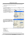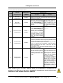
1
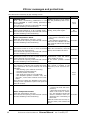
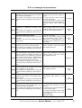
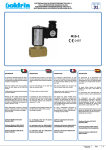
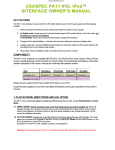
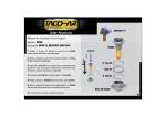
VIALE STAZIONE 5 - 36054 MONTEBELLO VIC. - VI - ITALY
Phone (+39) 0444 440441 - Fax (+39) 04444 440418
www.AXORINDUSTRIES.COM - [email protected]
6) Speeder One
Alarms Manual
ver.1 rev.06/'07
Enclosures to Service Manuals of:
• McbNET DigitalTM
• Magnum400TM
• MiniMagnum400TM
Enclosure to Service Manual
Alarms Manual ver.1 rev.06/'07
1
Summary
1
2
3
4
5
6
Protections
Error messages and protections
Alarms window
Reset Fault Function
Management via Modbus
Stop due an alarm
Release
3
4
7
8
9
10
Notes
ver.1 rev.06/'07
Preliminary first edition.
All rights reserved. Reproduction in whole or in part is prohibited without prior
written consent of the copyright owner. All specifications are subject to change
without prior notification.
This manual has been carefully checked. However, Axor does not assume liability
for errors or inaccuracies.
Print in Italy 06/2007
THIS MANUAL IS EXCLUSIVELY ADDRESSED TO TECHNICAL PERSONNEL WITH
AN APPROPRIATE TECHNICAL KNOWLEDGE ON SERVODRIVES.
BEFORE USING THIS MANUAL READ DRIVE'S SERVICE MANUAL AND ENCLOSURE
"SPEEDER ONE INTERFACE".
2
Enclosure to Service Manual
Alarms Manual ver.1 rev.06/'07
1 Protections
Axor digital drives are equipped with a series of protections which safeguard both the drive and the
motor in case of malfunctions.
There are three kinds of protection: reversible, resettable and irreversible.
Reversible protection intervention
It compares in presence of alarms which “reset itself” when the cause that has determined intervention is no longer present.
This causes the block of the drive. To restore the correct functioning it is necessary to:
1) disable the drive (using the “Disable” icon or the DGT-IN1 input);
2) eliminate the cause that has determined intervention;
3) enable the drive (using the “Enable” icon or the DGT-IN1 input).
Resettable protection intervention
It compares in presence of alarms which “can be reset” using the “Reset Fault” function.
This causes the block of the drive. To restore the correct functioning it is necessary to:
1) disable the drive (using the “Disable” icon or the DGT-IN1 input);
2) reset the alarm using the “Reset Fault” function;
3) enable the drive (using the “Enable” icon or the DGT-IN1 input).
Irreversible protection intervention
It compares in presence of alarms which "cannot be reset”.
This causes the disabling of the drive. To restore the correct functioning it is necessary to:
1) Disconnect the power (main power supply and auxiliary power supply);
2) eliminate the cause of the block;
3) power again.
N.B. Before powering again wait a short while until the drive is securely switched off.
Note: In some cases (Alarm 6, Alarm 10, 24 UP) the drive is not disable and the control visualises
only a message without change the system’s functioning.
Eventual functioning errors are visualized on the drive's display, besides they can be controlled by
using Speeder One interface.
Enclosure to Service Manual
Alarms Manual ver.1 rev.06/'07
3
2 Error messages and protections
The table below illustrates all the message errors:
ALARM
4
SOLUTION
RESET
AL1
EEPROM alarm
Disable the drive, try to memoError while memorising parameters to the rise the parameter, then re-endrive's EEPROM or while reading parameters able.
from Eeprom.
This causes the opening of the Relè OK contact
and the disabling of the functioning.
Reset
itself
AL2
Overcurrent alarm
Disconnect the power, verify the
Short circuit between U, V, W or toward earth.
wiring, then power again.
This causes the opening of the Relè OK contact
and the disabling of the functioning.
Not
resettable
AL3
Disable the drive, verify:
• the forced ventilation funcDrive Temperature alarm
tioning,
Heat sink temperature too high, >75°C.
Resettable
• the ambient temperature,
This causes the opening of the Relè OK contact
wait until the radiator has cool
and the disabling of the functioning.
off, reset the alarm then enable
the drive.
AL4
Hall alarm
Disable the drive, verify the
This alarm comes on if one or more of the hall cell's wire connection, reset the
Resettable
cell's wires are disconnected.
alarm, then enable the drive.
This causes the opening of the Relè OK contact
and the disabling of the functioning.
AL5
Encoder alarm
This alarm comes on if one or more of the encoder channels are interrupted.
This causes the opening of the Relè OK contact
and the disabling of the functioning.
Disable the drive, control the
connections, reset the alarm,
Resettable
then enable the drive.
If the alarm persists contact
Axor.
It is only a message.
The current is limited to the
rated one, set in "Current" window.
AL6
I2t Drive alarm
The internal I2t function has reached the maximum permitted. The cause could be one of the
following:
• the working cycle could be too heavy;
• a possible mechanical block;
• a motor phases inversion;
• the electronic brake is not unblocked;
• the amplifier dynamic costants: "KP", "KI"
and "KD", could create useless current oscillation.
This does not cause the disabling of the functioning, but it is possible to open or not open the
Relè OK contact.
AL7
Disable the drive:
• control the heat sink temperature;
• decrease the dynamic conMotor Temperature alarm
stant if the motor is vibrating. This situation causes the
Heat sink temperature too high.
Resettable
This causes the opening of the Relè Ok contact
current oscillation and conand the disabling of the functioning.
sequently the overheating of
the motor.
Wait the motor has cool off, reset the alarm, then enable the
drive.
Enclosure to Service Manual
Alarms Manual ver.1 rev.06/'07
Reset
itself
2 Error messages and protections
AL8
Regenerative Resistance alarm
Disable the drive:
The value I2t energy recovery has reached
• check the AC power supply inthe maximum permitted.
put;
This causes the opening of the Relè Ok
• check that the working cycles
contact and the disabling of the functionare not excessive;
ing.
• verify if the motor, going at half
speed, shows the same problem.
Reset the alarm, then enable the
drive.
AL9
Min/Max Voltage alarm
Minimum or maximum converter voltage.
This causes the opening of the Relè Ok
contact and the disabling of the functioning.
Disable the drive, wait the DC power
supply voltage reaches the correct
threshold, check the AC power supply input, then enable the drive.
Pre-Alarm Recovery alarm
80% of the I2t energy recovery has been
reached.
AL10
This does not cause the disabling of the
functioning.
It is only a message.
Check the AC power supply input
and the working cycles. This is a
visual alarm, it anticipates the intervention of the "Maximum recovery" alarm.
Resolver alarm
Disable the drive, control the reMissing one or more resolver signals.
solver's contact, reset the alarm,
AL12 This causes the opening of the Relè Ok then enable the drive.
contact and the disabling of the functioning.
Following Error
The error between the position reference
and the position feedback exceeds the
"Max Position Error" parameter, because
of the "Max Position Error" parameter is
AL14
too small, or the dynamic gains of the
velocity-positioning loop are wrong.
This causes the opening of the Relè Ok
contact and the disabling of the functioning.
Resettable
Reset
itself
Reset
itself
Not
resettable
Disable the drive, check the Max
Position Error parameter, check the
dynamic gains, reset the alarm,
then enable the drive.
Resettable
Limit Switch
Disable the drive, check the limit
The two fixed limit switches have both switches and external connections,
been disabled or interrupted.
then enable the drive.
AL15
This causes the opening of the Relè Ok
contact and the disabling of the functioning.
Reset
itself
Overcurrent regen resistance circuit Power off the drive, control the
Possible short-circuit in the regen resist- short-circuit, then power on the
ance circuit.
drive.
AL17
This causes the opening of the Relè OK
contact and the disabling of the functioning.
Not
resettable
Mechanical Brake
Disconnect the power:
Overcurrent at the internal brake com• control the external connecmand or wrong connections.
tions;
This causes the opening of the Relè Ok
• control the current absorption
AL18 contact and the disabling of the functionof the motor brake;
ing.
• verify the settings of the "Holding Brake" parameter on the "Motor" window;
then power again.
Not
resettable
Enclosure to Service Manual
Alarms Manual ver.1 rev.06/'07
5
2 Error messages and protections
24
UP
In-rush Bus
This is not an alarm.
It is only a message.
Indication of the drive's in-rush phase or
the lack of the main supply.
Reset
itself
Auxiliary Voltage
Disable the drive, then connect the
Presence of the main supply (L1, L2, L3), Auxiliary Voltage and then re-enbut the auxiliary +24Vdc voltage is miss- able.
Resettable
AL20 ing.
This causes the opening of the Relè Ok
contact and the disabling of the functioning.
Flash Alarm
Disable the drive, save new valErrors in reading/writing parameters on ues, then re-enable. If the probFlash, or Flash is empty.
lem persists contact Axor.
AL23
This causes the opening of the Relè Ok
contact and the disabling of the functioning.
Reset itself
Can Bus Alarm
Disable the drive, check the caError
during
communication
with bling and re-enable. If the problem
CanOpen protocol.
persists contact Axor.
Resettable via
AL24
Can Master
This causes the opening of the Relè Ok
contact and the disabling of the functioning.
Homing Error
Check the homing setup, then
Position error too high during the homing reset the alarm using the "Start
AL26
procedure.
Homing" function.
The motor stops, but it is not disabled.
If the provided solutions do not solve the alarm, contact Axor.
ATTENTION: McbNET DigitalTM does not manage alarms AL17, AL18 and AL20.
6
Enclosure to Service Manual
Alarms Manual ver.1 rev.06/'07
Resettable
with
Start Homing
function
3 Alarms window
Speeder One interface allows you to control the history of the drive’s alarms and the status of them,
by openig "Alarm" window:
There are not active alarms
There are active alarms
Clicking on Empty/Present button "Alarms" window opens:
A red dot and the red symbol near the alarm name indicate that the alarm is currently on, while
a red checkmark signifies that the alarm has been resolved.
It is possible to reset the history of the alarms by disabling and enabling the drive or clicking on
“Reset Historic Alarms”.
Enclosure to Service Manual
Alarms Manual ver.1 rev.06/'07
7
4 Reset Fault Function
The "Reset Fault" function, that can be set on one of the programmable digital inputs in the Digital
I/O window, allows you to reset all resettable alarms.
The resettable alarms are the following:
•
•
•
•
•
•
AL3: Drive's temperature;
AL4: Hall;
AL5: Encoder;
AL7: Motor's temperature;
AL8: Regenerative Resistance;
AL14: Following Error.
When a resettable alarm occurs the motor is blocked; to restore the correct functioning it is necessary
to:
1) disable the drive (using the "Disable" icon and/or DGT-IN1 input);
2) eliminate the cause that has determined intervention;
3) reset the alarm by setting the "Reset Fault" function in one of the available programmable digital inputs and applying a high logic signal to this input (see note below);
4) enable the drive (using the "Enable" icon and/or DGT-IN1 input).
Note: It is possible to apply a high logic signal to the input in two modes:
- utilising the Speeder One interface: clicking on the button near the name of the digital input
which will then show red on the “St” led.
- hardware: by applying the corresponding voltage on the connector pins. This will cause leds “St”
and “Hw” to show red.
Reset Fault function sequence:
ON
resettable
ALARM
OFF
T
ENABLE
INT
ON
OFF
T
+24V
ENABLE
(DGT-IN1)
0V
T
RESET
FAULT
+24V
0V
T
8
Enclosure to Service Manual
Alarms Manual ver.1 rev.06/'07
5 Management via Modbus
Parameters: Alarms HI (address 51), Alarms LO (address 52), Historic Alarms HI (address 83),
Historic Alarms LO (address 84), allows you to control alarms currently on and the history of alarms
via ModBus.
The following table illustrate the meaning of each bit:
Alarms HI and Historic Alarms HI
Bit
Description
0
Eeprom alarm
1
Overcurrent alarm
2
Drive temperature alarm
3
Hall alarm
4
Encoder alarm
5
I2t drive alarm
6
Motor temperature alarm
7
Regen resistance alarm
8
Min/Max voltage alarm
9
NA
10
NA
11
Resolver alarm
12
NA
13
Following error alarm
14
Limit switch alarm
15
NA
Alarms LO and Historic Alarms LO
0
Overcurrent regen resistance alarm (only Magnum400 and MiniMagnum)
1
Holding brake alarm (only Magnum400 and MiniMagnum)
2
In-rush bus alarm (only Magnum400 and MiniMagnum)
3
Auxiliry voltage alarm (only Magnum400 and MiniMagnum)
4
NA
5
NA
6
Flash alarm
7
CanBus alarm
8
NA
9
Homing alarm
10
NA
11
NA
12
NA
13
NA
14
NA
15
NA
You can find more information about ModBus management on enclosure "ModBus Manual" available
on the CD provided with the drive.
Enclosure to Service Manual
Alarms Manual ver.1 rev.06/'07
9
6 Stop due an alarm
In the following pages we illustrate the behaviour of the system in reference to these settings:
automatic or manual management of the stationary brake;
emergency stop.
We remember that:
• For the manual management of the brake it is necessary to set the "With" option in the "Holding Brake" box in the "Motor" window, then it is necessary to select the "Brake" function on one
of the programmable digital inputs.
• For the automatic management of the brake it is only necessary to set the "With" option in the
"Holding Brake" box in the "Motor" window (Attention: Do Not select the "Brake" function on one
of the programmable digital inputs).
• For the no management of the brake by drive
it is necessary to set the "Without" option in the
"Holding Brake" box in the "Motor" window.
• For the emergency stop function it is necessary to set the dedicated flag in the "General
Set" window, and to set the "Emer. Ramp"
parameter [in ms] in the "Speed" window.
Note: In the operative mode "7:CAN open"
the "Emer.Ramp" parameter is set via
CanBus.
The dangerous alarms, which cause the immediately insertion of the brake, are the followings:
- Al2: Over Current;
- Al4: Hall;
- Al5: Encoder;
- Al9: Max/Min Voltage;
- Al12: Resolver;
- Al14: Following Error;
- Al17: Over Current Brake.
All others alarms stop the system by using the emergency ramp before the brake's insertion.
10
Enclosure to Service Manual
Alarms Manual ver.1 rev.06/'07
6 Stop due an alarm
This table illustrates all possible cases:
BEHAVIOUR
CASES
BRAKE
MANAGEMENT
1°
No brake
management
2°
3°
4°
No brake
management
Automatic brake
management
Manual brake
management
EMERGENCY
STOP
FUNCTION
Disable
Enable
NOT DANGEROUS
ALARM
The internal enable immediately disables, the motor
remains free and will eventually stop due to the friction
and inertia of the axis.
The motor stops following
an emergency ramp equal
to the "Emer. Ramp" parameter set in the "Speed"
window.
Manual brake
management
The internal enable immediately disables, the
motor remains free and
will eventually stop due to
the friction and inertia of
the axis.
Enable or
Disable
The motor stops following The brake is immediately
an emergency ramp equal activated.
to the "Emer. Ramp" parameter set in the "Speed"
window; when 3% of the
max speed is reached
the brake output is disabled, then after the motor
stops, the internal enable
disables.
Disable
The internal enable disables, the motor remains free
and will eventually stop due to the friction and inertia
of the axis; after the motor stops it is possible to block
the axis enabling the brake command.
In particular conditions (for example: having a vertical
axis), it is possible to immediately enable the brake
without waiting the axis' stop the motor will stop
due to the friction.
ATTENTION: THE TIME FOR BRAKE ENABLE IS DECIDED BY THE USER.
The motor stops following the emergency ramp;
after the motor stops it is
possible to block the axis
enabling the brake command.
5°
DANGEROUS
ALARM
Enable
The motor remains free
and will eventually stop
due to the friction and inertia of the axis; after the
motor stops it is possible
to block the axis enabling
the brake command.
In particular conditions
(for example: having a
vertical axis), it is possible
to immediately enable the
brake without waiting the
axis' stop the motor will
stop due to the friction.
ATTENTION: THE TIME
FOR BRAKE ENABLE IS
DECIDED BY THE USER.
NOTE: McbNET DigitalTM DOES NOT MANAGE BRAKE, SO IN PRESENCE OF A DISABLE OR AN
ALARM IT FOLLOWS CASE 1° OR CASE 2° DEPENDENT ON EMERGENCY STOP FUNCTION SETTINGS SET IN THE "GENERAL SETTING" WINDOW.
Enclosure to Service Manual
Alarms Manual ver.1 rev.06/'07
11
12
Enclosure to Service Manual
Alarms Manual ver.1 rev.06/'07