1
DDM-2000 OC-3 Multiplexer
Release 13.0 and Later
User/Service Manual — Volume I
363-206-285
Issue 3
June 2001
Copyright© 2001 Lucent Technologies, All Rights Reserved.
This material is protected by the copyright laws of the United States and other countries. It may not be
reproduced, distributed or altered in any fashion by any entity, including other Lucent Technologies Business
Units or Divisions, without the expressed written consent of the Customer Training and Information Products
organization.
For permission to reproduce or distribute, please contact:
Product Development Manager 1-888-LTINFO6 (1-888-584-6366).
Notice
Every effort was made to ensure that the information in this document was complete and accurate at the time of
printing. However, information is subject to change.
Mandatory Customer Information
Interference Information: Part 15 of Federal Communications Commission (FCC) Rules.
NOTE: This equipment has been tested and found to comply with the limits for a Class A digital device, pursuant
to Part 15 of the FCC rules. These limits are designed to provide reasonable protection against harmful
interference when the equipment is operated in a commercial environment. This equipment generates, uses, and
can radiate radio frequency energy and, if not installed and used in accordance with the instruction manual, may
cause harmful interference to radio communications. Operation of this equipment in a residence is likely to cause
harmful interference in which case the user will be required to correct the interference at his own expense.
Security Statement
In rare instances, unauthorized individuals make connections to the telecommunications network through the
use of remote access features.
In such event, applicable tariffs require that the customer pay all network charges for traffic. Lucent Technologies
cannot be responsible for such charges and will not make any allowance or give any credit for charges that result
from unauthorized access.
Trademarks
5ESS, DACScan, LGX, SLC, ST, and Western Electric are registered trademarks of Lucent Technologies, Inc.
ANSI is a registered trademark of American National Standards Institute, Inc.
Common Language is a registered trademark, and CLEI, CLLI, CLCI, and CLFI are trademarks of Bell
Communications Research, Inc.
DEC is a trademark of Digital Equipment Corporation.
Gateway 2000 is a registered trademark of Gateway 2000, Inc.
Hayes is a registered trademark of Hayes Microcomputer Products, Inc.
HP is a registered trademark of Hewlett-Packard Company.
IBM is a registered trademark of International Business Machines Corporation.
IEEE is a registered trademark of The Institute of Electrical and Electronics Engineers, Inc.
MegaStar is a registered trademark of Harris Corporation.
Microsoft, MS-DOS, and Windows are registered trademarks of Microsoft Corporation.
National Electrical Code is a registered trademark of National Fire Protection Association, Inc.
NCR is a trademark of NCR Corporation.
NEC is a registered trademark of Nippon Denki Kabushiki Kaisha.
NMA and TIRKS are registered trademarks of Bell Communications Research, Inc.
PairGain is a registered trademark of PairGain Technologies, Inc.
Paradyne is a registered trademark of AT&T.
Penril is a registered trademark of Penril Corporation.
PROCOMM is a registered trademark of Datastorm Technologies, Inc.
RIDES is a registered trademark of Ericsson Raynet.
SAFARI is a registered trademark of AT&T.
SPARC is a registered trademark of SPARC International, Inc. licensed exclusively to SUN Microsystems, Inc.
Styrofoam is a registered trademark of The Dow Chemical Company.
SUN is a registered trademark of SUN Microsystems, Inc.
Titan is a registered trademark of Tellabs, Inc.
V-Series is a registered trademark of General Electric Capital Corporation.
Warranty
Lucent Technologies provides a 5-year limited warranty to this product. For more information, consult your
local Account Executive.
Document Ordering Information
The ordering number for this document is 363-206-200. To order this document, call 1-888-582-3688. For
more ordering information, refer to “How to Order Documents” in the section “About This Document.”
Customer Assistance and Technical Support
The Lucent Technologies Regional Technical Assistance Center (RTAC) provides a technical assistance
telephone number which is staffed 24 hours a day. For technical assistance, simply call 1-800-225-RTAC in
accordance with local operating procedures.
Documentation Support Telephone Number
Lucent Technologies provides a telephone number for you to report errors or to ask questions about the
information in this document. The support telephone number is 1-978-960-6838.
Developed by Lucent Technologies Network Systems Customer Training and Information Products.
Contents
About This Document
xxix
■
Purpose
xxix
■
Intended Audiences
xxix
■
Reason for Reissue
xxx
■
Operations Interworking using TARP
xxxi
■
Safety Instructions
xxxiii
Product Safety Labels
xxxiii
Lightwave Safety Guidelines
xxxiii
Electrostatic Discharge (ESD) Considerations
xxxvi
■
Related Documentation
xli
■
Related Training
xlvii
■
Customer Technical Support (CTS)
l
■
Engineering and Installation Services
liii
Customer Technical Support Enhanced Services
■
Documentation Support
liv
■
How to Order Documents
lv
Standing Orders
1
liv
lvi
■
How to Comment on This Document
lvi
■
Electronic Documentation
lvi
System Introduction
1-1
■
Overview
1-1
■
Lucent 2000 Product Family
1-1
■
DDM-2000 Product Family
1-3
■
Introduction to the DDM-2000 OC-3 Multiplexer
1-5
■
DDM-2000 OC-3 Multiplexer Releases
1-6
■
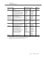
Release Descriptions
1-6
DDM-2000 OC-3 Multiplexer
Release 13.0
1-16
Release Description
1-16
Issue 3 June 2001
v
Contents
2
Applications
2-1
■
Overview
2-1
■
Introduction
2-2
■
Network Configurations
2-3
Path Switched Rings
2-3
Dual Homing
2-25
Dual Ring Interworking (DRI)
2-27
Dual Homing with DRI
2-33
OC-3/OC-12 Linear Optical Extensions from
OC-3, OC-12, and FT-2000 Rings
2-34
Hairpin Cross-Connections on Rings
2-35
Point-to-Point Topologies
2-41
2000 Product Family Interworking
2-46
Multi-Vendor OI Applications
2-51
■
3
Service Applications
2-52
Loop Feeder
2-52
Interoffice Transport
2-52
Broadband Business Access
2-53
LAN/WAN Data Networking
2-55
Gateway Between SONET and Asynchronous
Interfaces
2-59
Locked STS-3c (0x1) Broadband Services
2-60
Teleprotection and SCADA Applications
2-62
Intelligent Vehicle Highway System (IVHS)
Applications
2-64
DS1 Performance Monitoring for Tariff Verification
2-66
DS3 Transmultiplexer (TMUX) Application.
2-68
High Bit Rate Subscriber Line (HDSL) Application.
2-69
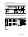
Shelf Descriptions and Configurations
3-1
■
Overview
3-1
■
DDM-2000 OC-3 Multiplexer Shelf
3-1
vi Issue 3 June 2001
Contents
4
5
■
DDM-2000 OC-3 Shelf Capacity
3-8
■
Shelf Configurations
3-9
■
DDM-2000 Fan Shelf
3-25
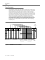
Power
4-1
■
Overview
4-1
■
Introduction
4-1
■
Power Description
4-2
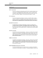
Circuit Packs
4-3
LEDs
4-5
Power Minor Alarm
4-5
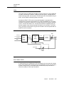
Power Distribution
4-6
Transmission and Synchronization Interfaces
5-1
■
Overview
5-1
■
Transmission Interfaces
5-2
■
Ring Interfaces
5-16
■
OC-3/OC-12 Ring (0x1)
5-16
DS3 Data Services on an OC-3 Ring
5-19
OC-3/OC-1 Ring (0x1)
5-20
OC-1 Ring Function Unit Pass-Through
5-23
OC-1/OC-1 Function Unit Hairpin Ring
5-24
Synchronization Interfaces
5-28
Timing Modes
5-28
Free-Running
5-28
DS1 Output Modes: MULT and SYNC OUT
5-29
Synchronization Messaging
5-34
Dual Homing DRI Synchronization Configurations
5-50
OC-3 and OC-1 External/Line Timing
5-54
Network Timing Distribution
5-56
Issue 3 June 2001
vii
Contents
6
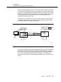
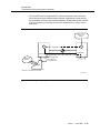
Operations Interfaces
■
Overview
6-1
■
Craft Interface Terminals (CIT)
6-2
■
■
Local Access
6-4
Using a PC as a CIT
6-6
Modem Access
6-6
Remote Access Using the Data Communications
Channel (DCC)
6-7
CPro-2000 Graphical User Interface and
Provisioning Tool
6-8
User Panel
6-8
User Panel LEDs
6-10
FE SEL Pushbutton
6-10
ACO/TST Pushbutton
6-10
UPD/INIT Pushbutton
6-11
Pushbutton Combinations
6-11
Equipment Indicators
6-12
FAULT Indicators
6-12
ACTIVE Indicators
6-12
■
Office Alarms
6-13
■
TL1/X.25 Interface
6-14
ITM SNC
7
6-1
6-14
■
IAO LAN Interface
■
User-Definable Miscellaneous Discretes—Environmental
Alarms and Controls
6-16
■
Order Wire
Circuit Pack Descriptions
6-15
6-18
7-1
■
Overview
7-1
■
Introduction
7-1
■
Compatibility
7-2
■
Control
7-2
viii Issue 3 June 2001
Contents
■
■
■
8
BBG8/BBG8B SYSCTL Circuit Pack Description
7-3
BBG9 OHCTL Circuit Pack Description
7-10
Synchronization
7-15
Synchronization Functions
7-15
BBF2B/BBF4 TGS/TG3 Circuit Pack Description
7-15
Transmission - Electrical Interface
7-25
BBF1/BBF1B DS1 Circuit Pack Description
7-25
BBF3/BBF3B DS1PM Circuit Pack Description
7-33
177A Retainer Card Description
7-41
BBF5 Jumper Circuit Pack Description
7-43
BBF8 High bit rate Digital Subscriber Line
7-44
BBF9/BBF10 IMA LAN Circuit Pack Description
7-53
BBG2/22G2B MXRVO Circuit Pack Description
7-61
BBG4/BBG4B DS3 Circuit Pack Description
7-66
BBG6 STS1E Circuit Pack Description
7-74
BBG19 DS3 Data Services Interface Circuit Pack
Description
7-84
BBG20 Transmultiplexer
7-91
Transmission - Optical Interface
7-99
Universal Optical Connector
7-99
22F/22F-U/22F2-U OLIU Circuit Pack Description
7-103
22D-U OLIU Circuit Pack Description
7-111
22G-U/22G2-U/22G3-U/22G4-U OLIU Circuit Pack
Description
7-118
24G-U OLIU Circuit Pack Description
7-126
26G2-U Circuit Pack Description
7-134
27G-U/27G2-U OLIU Circuit Pack Description
7-141
Administration and Provisioning
8-1
■
Overview
8-1
■
Administration
8-1
Version Recognition
8-1
Security
8-2
Issue 3 June 2001
ix
Contents
Software Upgrades
8-4
Software Compatibility
8-4
Controller Maintenance and Memory Administration 8-5
System Backup and Restoral
■
■
Multiplexing and Mapping
8-6
8-8
DS1 to OC-1/OC-3/OC-12
8-8
DS3 to OC-3/OC-12
8-12
EC-1 to OC-1/OC-3/OC-12
8-12
OC-1/OC-3/OC-12 to OC-1/OC-3/OC-12
8-13
DS3 to EC-1 Hairpin
8-14
EC-1 to EC-1 Hairpin
8-14
Provisioning
8-15
General
8-15
Default Provisioning
8-15
Remote Provisioning
8-15
Automatic Provisioning
8-15
Feature Package Provisioning
8-16
Data Communications Channel (DCC) Provisioning 8-16
■
Operations Interworking (OI) Provisioning
8-17
Port State Provisioning
8-20
Channel State Provisioning
8-20
Line State Provisioning
8-21
AIS or Unequipped Provisioning
8-21
Cross-Connection Provisioning
8-22
Cross-Connection Types
8-23
Cross-Connection Provisioning Commands
8-26
Allowable Cross-Connects
8-27
OC-3 and OC-12 Ring Cross-Connection
Provisioning
8-42
T1/TMUX Cross Connection and Description
8-47
OC-3/OC-12 VT1.5 Path Switched Ring (0x1)
Single Homing
8-55
OC-3/OC-1 Ring Cross-Connection Provisioning
8-59
■
Switch Selectable Parameters
8-70
■
CIT Selectable Parameters
8-70
x Issue 3 June 2001
Contents
9
Maintenance Description
■
9-1
Overview
9-1
Three-Tiered Operations
■
■
9-1
Single-Ended Maintenance Philosophy
9-4
Multi-Vendor OI
9-6
SEO Network Element Status Using Alarm
Gateway NE
9-7
In-Service Upgrades
9-9
Software Upgrades
9-9
■
Software Compatibility
9-10
■
Maintenance Signaling
9-12
Non-Ring Interfaces
9-14
Ring Applications
9-18
■
■
Fault Detection, Isolation, and Reporting
9-23
Detection
9-23
Isolation
9-23
Reporting
9-23
Protection Switching
9-24
Automatic Line Protection
9-24
Path Protection Switching (Path Switched Rings)
9-27
Dual Ring Interworking (DRI)
9-32
OC-3/OC-12 Path Switched Ring (0x1)
9-34
OC-3/OC-1 Path Switched Ring (0x1)
9-34
Status of ACTIVE LED on Rings
9-34
Equipment Protection
9-34
Synchronization Reference Protection
9-35
■
Loopbacks
9-36
■
Tests
9-37
■
Transmission Tests
9-37
Automatic Turnup Tests
9-37
Operations Interface Tests
9-39
Performance Monitoring (PM)
9-40
VT Performance Monitoring
9-42
Issue 3 June 2001
xi
Contents
■
10
DS1 Performance Monitoring
9-42
DS3 Performance Monitoring
9-44
Optical Parameters
9-45
OC-3 Section Parameters
9-46
OC-3/EC-1 Line Parameters
9-46
STS-1 Path Parameters
9-48
VT1.5 Path Parameters
9-49
DS1 Path Parameters
9-50
DS1 Line Parameters
9-51
DS3 Parameters
9-52
OC-1 Section Parameters
9-55
OC-1 Line Parameters
9-55
OC-12 Line Parameter
9-57
Performance Monitoring Data Storage and Reports
9-59
Performance Monitoring During Failed Conditions
9-59
Performance Parameter Thresholds
9-59
TCA Transmission to OS
9-60
Performance Monitoring Reports
9-60
Reports
9-61
Alarm and Status Report
9-61
Provisioning Reports
9-61
Database Change Transmission to OS
9-61
Maintenance History Report
9-61
State Reports
9-62
Equipment Report
9-62
Neighbor Map Report
9-62
Network Map Report
9-62
Technical Specifications
10-1
■
Overview
10-1
■
DDM 2000 OC-3 Multiplexer
10-1
External Transmission Interfaces
xii Issue 3 June 2001
10-1
Contents
A
Electrical Interfaces
10-2
Plug-In Maintenance Sparing Guidelines
10-47
SONET Overhead Bytes
10-52
Performance
10-52
Operations Interfaces
10-58
Physical Specifications
10-66
Environmental Specifications
10-67
Power Requirements
10-69
DDM-2000 OC-3 Reliability
10-72
A SONET Overview
A-1
■
Overview
A-1
■
History
A-1
■
Basic Purpose
A-2
■
Technical Overview
A-2
■
■
SONET Signal Hierarchy
A-2
SONET Layers
A-4
SONET Frame Structure
A-6
Section Overhead
A-6
Line Overhead
A-7
Path Overhead
A-8
SONET Multiplexing Procedure
A-10
SONET Demultiplexing Procedure
A-12
SONET Digital Multiplexing Schemes
A-14
Virtual Tributary Signals
A-15
Concatenated Mode
A-16
SONET Interface
A-18
SONET Payloads
A-19
Higher Rate Transport
A-20
Conclusion
A-20
Issue 3 June 2001
xiii
Contents
GL
Glossary
xiv Issue 3 June 2001
GL-1
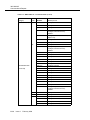
Figures
2
Applications
2-1
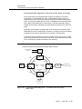
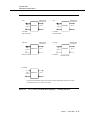
Path Switched Ring
2-5
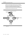
2-2
OC-3 Path Switched Ring
2-7
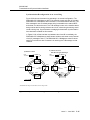
2-3
DDM-2000 OC-3 Path Switched Interoffice Ring
2-8
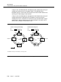
2-4
OC-12 Path Switched Ring — STS-1 Level Path
Switching
2-9
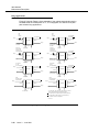
OC-12 Path Switched Ring Using OC-12
Multiplexer—Mixed STS-1 and VT1.5 Path
Switching
2-10
OC-12 VT Path Switched Ring Using DDM-2000
OC-3 Multiplexer With OC-12 Optics
2-11
2-5
2-6
2-7
OC-12 Path Switched Ring Using DDM-2000
OC-12, OC-3, and FiberReach Multiplexers With
OC-12 Optics
2-12
2-8
OC-3 Ring with OC-12 Ring Transport
2-13
2-9
Multinode OC-3 Ring With OC-12 Ring Transport
2-15
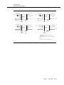
2-10
DDM-2000 OC-12 Path Switched Interoffice Ring
2-16
2-11
OC-12 Ring Transport (STS-1/VT1.5 0x1) With
FiberReach OC-3 Rings
2-18
2-12
Folded Ring Configuration
2-20
2-13
OC-1 Ring Transport on OC-3 Ring Configuration 2-22
2-14
DDM-2000 FiberReach Stand-Alone OC-1 Ring
2-23
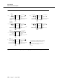
2-15
DDM-2000 FiberReach Single Homing to a
Stand-Alone OC-1 Hub Host
2-24
DDM-2000 FiberReach Dual Homing to a
DDM-2000 OC-3 Ring
2-26
2-17
Dual Access Configuration
2-28
2-18
Dual Ring Interworking Concepts
2-29
2-19
OC-3/12 to FT-2000 OC-48 Lightwave System Dual
Ring Interworking
2-31
2-20
DDM-2000 Ring Interworking with FT-2000
OC-48 Lightwave System Transport and
DACS IV-2000 Grooming
2-16
2-32
Issue 3 June 2001
xv
Figures
2-21
DDM-2000 FiberReach Ring Dual Homing to a
DDM-2000 OC-3 Ring in a Dual Wire Center
Application
2-33
2-22
VT1.5 Hairpin Cross-Connections
2-35
2-23
OC-1 Ring Pass-Through in a Function Unit
2-37
2-24
Single-Homed Hairpin Routing
2-38
2-25
Dual-Homed Hairpin Routing
2-39
2-26
Hairpin Local Drop Routing
2-40
2-27
OC-3 Point-to-Point Topology (Folded Ring)
2-42
2-28
Metro Application — Copper in the Riser
2-43
2-29
Metro Application — Fiber in the Riser
2-44
2-30
Campus CENTREX Configuration
2-45
2-31
OC-3 Loop Carrier Interface Configuration
2-46
2-32
Operations Interworking Application
2-47
2-33
OC-3 Ring Interfaces with FT-2000 OC-48
Lightwave System
2-48
OC-3 Linear Extension from FT-2000 Lightwave
System
2-49
OC-3 Ring Interfaces with FT-2000 OC-48
Lightwave System
2-50
Interworking of OC-1/OC-3/OC-12/OC-48 with
Tellabs TITAN 5500 DCS
2-51
2-34
2-35
2-36
2-37
Self-Healing Medical Campus Network Application 2-54
2-38
LAN/WAN Data Networking Using DS1/VT
Cross-Connections
2-56
2-39
LAN/ATM Data Networking Using Transmultiplexer
Circuit Pack
2-57
2-40
DDM-2000 Data Service with ATM Switch
2-41
OC-12 STS-1 Drop-and-Continue to DS3 Interfaces2-60
2-42
Locked (0x1) STS-3c - Broadband Services Using
DDM-2000 OC-3 Multiplexer With OC-12 Optics 2-61
2-43
Teleprotection and SCADA Application
2-63
2-44
Intelligent Vehicle Highway System (IVHS)
Application
2-65
xvi Issue 3 June 2001
2-58
Figures
2-45
3
DS1 Path Performance Monitoring for Tariff
Verification
2-67
2-46
DS3 Transmultiplexer Application
2-68
2-47
HDSL Application
2-70
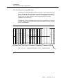
Shelf Descriptions and Configurations
3-1
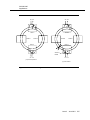
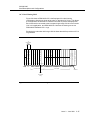
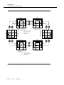
DDM-2000 OC-3 Group 4 Shelf — Front View
3-3
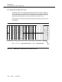
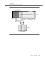
3-2
DDM-2000 OC-3 Shelf — Rear View
3-3
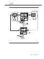
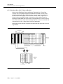
3-3
DDM-2000 OC-3 Multiplexer Front Panel
3-7
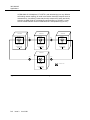
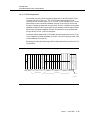
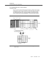
3-4
DDM-2000 OC-3 Ring Shelf
3-12
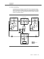
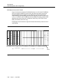
3-5
DDM-2000 OC-3 DRI Shelf
3-13
3-6
DDM-2000 OC-3 Ring Shelf With an Optical
Extension
3-14
3-7
DDM-2000 OC-3 VT/STS Hairpin Shelf
3-15
3-8
DS3 Data Services in OC-3 Shelf
3-16
3-9
DDM-2000 OC-3 Dual Homing Shelf
3-17
3-10
OC-3 DDM-2000 FiberReach Host Shelf
3-19
3-11
OC-3 DDM-2000 FiberReach Host Shelf Enhanced Routing Topologies
3-20
OC-3 DDM-2000 FiberReach Host Shelf Enhanced Routing with 26G2-U OLIU
3-21
3-13
OC-3/OC-12 Shelf with LAN Interface
3-22
3-14
OC-3/OC-12 Shelf with HDSL Interface
3-23
3-15
OC-3/OC-12 Shelf with Transmultiplexers
3-24
3-16
DDM-2000 Fan Shelf
3-25
3-17
DDM-2000 Fan Shelf — Fan Switches — Front
Cover Removed
3-26
DDM-2000 OC-3 Power Architecture
4-2
3-12
4
Power
4-1
Issue 3 June 2001
xvii
Figures
5
4-2
Circuit Pack Power and LED Control
4-5
4-3
Typical -48 Volt Power Supply for DDM-2000
OC-3 Multiplexer Single Shelf
4-6
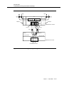
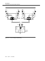
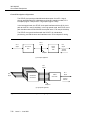
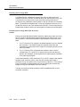
Transmission and Synchronization Interfaces
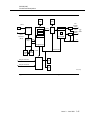
5-1
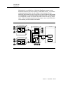
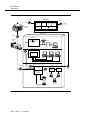
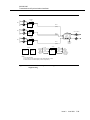
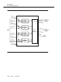
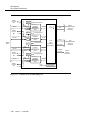
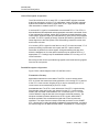
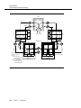
DDM-2000 OC-3 Multiplexer Block
Diagram — Terminal
5-3
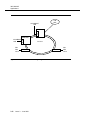
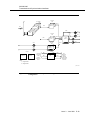
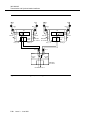
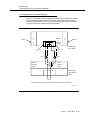
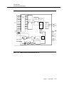
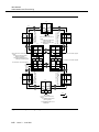
DDM-2000 OC-3 Multiplexer Block
Diagram — STS-1 Drop
5-5
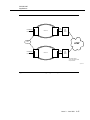
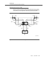
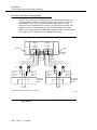
DDM-2000 OC-3 Multiplexer Block
Diagram — Hubbing
5-6
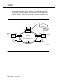
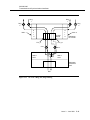
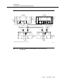
DDM-2000 OC-3 Multiplexer Block
Diagram — DS1/DS3/EC-1 Add/Drop,
and VT1.5/STS-1 Path Switched Ring
5-8
DDM-2000 OC-3 Multiplexer with OC-12 Optics
Block Diagram
5-9
DDM-2000 OC-3 Multiplexer Block
Diagram — DDM-2000 FiberReach
Host — Single Homing
5-11
DDM-2000 OC-3 Multiplexer Block
Diagram—FiberReach Stand-Alone
Host Configuration
5-13
5-8
Single Homing with 27G-U Dual OC-1 OLIUs
5-15
5-9
OC-3/OC-12 Ring (0x1) Single Homing
5-17
5-10
OC-3/OC-12 Ring (0x1) Dual Homing
5-18
5-11
DS3 Data Services on an OC-3 Ring
5-19
5-12
OC-3/OC-1 Ring (0x1) Single Homing
5-21
5-13
OC-3/OC-1 Ring (0x1) Dual Homing
5-22
5-14
OC-1 Ring Function Unit Pass-Through
5-23
5-15
OC-1/OC-1 Function Unit Hairpin Ring—
Inter-Function Unit Single Homing
5-24
OC-1/OC-1 Function Unit Hairpin Ring—
Inter-Function Unit Dual Homing
5-25
5-2
5-3
5-4
5-5
5-6
5-7
5-16
xviii Issue 3 June 2001
Figures
5-17
OC-1/OC-1 Function Unit Hairpin Ring—
Intra-Function Unit Single Homing
5-26
OC-1/OC-1 Function Unit Hairpin Ring—
Intra-Function Unit Dual Homing
5-27
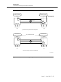
Synchronization Timing Configurations
(Sheet 1 of 2)
5-31
5-20
DS1 Timing Output — Dual Homing Linear
5-36
5-21
Synchronization Reconfiguration — Access Ring
5-38
5-22
Synchronization Reconfiguration — Externally
Timed Access Ring (Sheet 1 of 2)
5-43
Synchronization Reconfiguration — Access Ring
(Sheet 1 of 3)
5-45
5-18
5-19
5-23
6
7
5-24
DS1 Timing Output with Fiber Failure (Sheet 1 of 2 )5-48
5-25
OC-3 and FT-2000 OC-48 Lightwave System Dual
Homing DRI Configuration
5-51
5-26
OC-3 and OC-12 Dual Homing DRI Configuration
5-53
5-27
OC-3 and OC-1 External/Line Timing
5-55
5-28
OC-N Derived DS1 Timing Reference
5-57
5-29
Timing from Multiplexed DS1
5-59
Operations Interfaces
6-1
Craft Interface Terminal Connectors
6-4
6-2
Craft Interface Terminal Login Sessions
6-5
6-3
User Panel for Group 4 Shelf
6-9
6-4
Miscellaneous Discretes
6-17
Circuit Pack Descriptions
7-1
BBG8/BBG8B SYSCTL Circuit Pack
7-3
7-2
BBG8/BBG8B SYSCTL Circuit Pack Block Diagram7-5
7-3
BBG8/BBG8B SYSCTL Option Switches
7-8
7-4
BBG9 OHCTL Circuit Pack
7-11
Issue 3 June 2001
xix
Figures
7-5
BBG9 OHCTL Circuit Pack Block Diagram
7-13
7-6
BBF2B TGS and BBF4 TG3 Circuit Pack
7-16
7-7
BBF2B TGS and BBF4 TG3 Circuit Pack Block
Diagram
7-18
TG Option Switches for DDM-2000 OC-3
(Sheet 1 of 2)
7-22
7-9
BBF1/BBF1B DS1 Circuit Pack
7-26
7-10
BBF1/BBF1B DS1 Circuit Pack Block Diagram
7-28
7-11
BBF1/BBF1B DS1 Option Switches
7-32
7-12
BBF3/BBF3B DS1PM Circuit Pack
7-34
7-13
DS1PM Circuit Pack Block Diagram
7-36
7-14
BBF3 DS1PM Option Switches
7-40
7-15
177A Retainer Card
7-42
7-16
BBF5 Jumper Circuit Pack
7-43
7-17
BBF8 HDSL Circuit Pack
7-44
7-18
HDSL Circuit Pack Block Diagram
7-46
7-19
HDSL DIP Switch Settings
7-51
7-20
BBF9/BBF10 IMA LAN Circuit Pack
7-53
7-21
BBF9/BBF10 IMA LAN Circuit Pack Block Diagram 7-57
7-22
IMA LAN Power Settings
7-60
7-23
BBG2 MXRVO Circuit Pack
7-61
7-24
BBG2 MXRVO Circuit Pack Block Diagram
7-63
7-25
BBG4B DS3 Circuit Pack
7-67
7-26
BBG4/BBG4B DS3 Circuit Pack Block Diagram
7-69
7-27
BBG4/BBG4B DS3 Line Build-Out (LBO) Jumpers 7-72
7-28
BBG6 STS1E Circuit Pack
7-75
7-29
STS1E Circuit Pack Low-Speed and High-Speed
Modes
7-76
7-30
BBG6 STS1E Circuit Pack Block Diagram
7-77
7-31
BBG6 STS1E Line Build-Out (LBO) Jumpers and
Mode Switch
7-81
7-32
BBG19 DS3 Circuit Pack
7-84
7-33
BBG19 DS3 Circuit Pack Block Diagram
7-86
7-34
BBG19 DS3 Line Build-Out (LBO) Jumpers
7-89
7-8
xx Issue 3 June 2001
Figures
8
7-35
TMUX Circuit Pack
7-92
7-36
TMUX Circuit Pack Block Diagram
7-94
7-37
BBG20 TMUX Line Build-Out (LBO) Jumpers
7-97
7-38
Universal Optical Connector
7-100
7-39
22F/22F-U/22F2-U OLIU Circuit Pack
7-104
7-40
22F-type OLIU Circuit Pack Block Diagram
7-107
7-41
22D-U OLIU Circuit Pack
7-111
7-42
22D-U OLIU Circuit Pack Block Diagram
7-113
7-43
22G-U/22G2-U/22G3-U OLIU Circuit Pack
7-119
7-44
22G-U/22G2-U/22G3-U/22G4-U OLIU Circuit Pack
Block Diagram
7-122
7-45
24G-U OC-12 OLIU Circuit Pack — 24G-U Pair with
Interconnect Cable Assembly
7-127
7-46
24G-U OLIU Circuit Pack Block Diagram
7-130
7-47
26G2-U OLIU Circuit Packs
7-135
7-48
26G2-U OLIU Circuit Pack Block Diagram
7-137
7-49
27G-U/27G2-U OLIU Circuit Pack
7-142
7-50
27G-U/27G2-U OLIU Circuit Pack Block Diagram
7-145
7-51
Optical System Interfaces (Points S and R)
7-151
Administration and Provisioning
8-1
Locked Cross-Connection
8-24
8-2
Example of STS-1 Addresses
8-41
8-3
Example OC-3 Ring Configuration
Cross-Connections
8-46
8-4
Drop and Continue Nodes
8-52
8-5
Example Dual Ring Configuration
Cross-Connections
8-54
Example OC-3/OC-12 0x1 Single Homing
Configuration Cross-Connections
8-58
Example OC-1 Ring Configuration
Cross-Connections
8-60
8-6
8-7
Issue 3 June 2001
xxi
Figures
8-8
8-9
8-10
9
Example Single-Homed Path-Switched Ring
Configuration Cross-Connections
8-63
Example Dual-Homed OC-3/OC-1 Path-Switched
Ring Configuration Cross-Connections
8-66
Locked (0x1) STS-3c - Broadband Services Using
DDM-2000 OC-12 Multiplexer
8-69
Maintenance Description
9-1
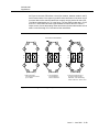
Three-Tiered Operations
9-3
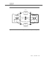
9-2
Single-Ended Operations
9-5
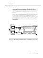
9-3
Example of Maintenance Signals as a Result of
Unprotected Incoming OC-3 Failure
9-13
DS1 Maintenance Signaling — Non-Ring
Interfaces
9-15
DS3 Maintenance Signaling — Non-Ring
Interfaces
9-16
OC-3 or EC-1 Line Maintenance Signaling —
Non-Ring Interfaces
9-17
9-7
Maintenance Signaling — VT Ring Application
9-18
9-8
Maintenance Signaling — VT Ring Application,
Unequipped
9-19
Maintenance Signaling — VT Ring Application,
TMUX circuit pack
9-20
9-10
Maintenance Signaling — STS Ring Application
9-21
9-11
Maintenance Signaling STS Ring Application —
Unequipped
9-22
9-12
Unidirectional Line Protection Switching
9-26
9-13
Two-Fiber Unidirectional Ring
9-28
9-14
Path Protection Switching
9-29
9-15
Locked DS3 Cross-Connect Path Protection
Switching
9-31
9-16
DRI Path Protection Switching
9-33
9-17
Local Equipment Test
9-39
9-18
Local Wiring Cross-Connect Test
9-39
9-4
9-5
9-6
9-9
xxii Issue 3 June 2001
Figures
9-19
9-20
10
A
DS1/DS3 Line and Path and DS3 Path
Performance Monitoring (PM)
9-41
DDM-2000 OC-3 Multiplexer DS1 Path
Performance Monitoring
9-43
Technical Specifications
10-1
T1EXT Span Powering
10-5
10-2
Optical System Interfaces (Points S and R)
10-26
10-3
Universal Optical Connector
10-50
A SONET Overview
A-4
SONET STS-1 Frame — Simplified Version
A-3
A-5
Section, Line, and Path Definitions
A-4
A-6
SONET Frame Format
A-5
A-7
VT Path Overhead Byte
A-9
A-8
SONET Multiplexing Procedure
A-11
A-9
SONET Demultiplexing Procedure
A-12
A-10
STS-1 Synchronous Payload Envelope in Interior
of STS-1 Frame
A-13
A-11
Asynchronous Multiplexing
A-14
A-12
Synchronous Multiplexing
A-15
A-13
STS-3c Concatenated Payload
A-17
A-14
SONET Interface
A-18
Issue 3 June 2001
xxiii
Figures
xxiv Issue 3 June 2001
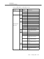
Tables
3
Shelf Descriptions and Configurations
3-1
DDM-2000 OC-3 Plug-Ins
3-4
3-2
DDM-2000 OC-3 Multiplexer Circuit Pack and
Software Compatibility Matrix
3-10
DDM-2000 Fan Shelf Switch Settings
3-27
3-3
5
Transmission and Synchronization Interfaces
5-1
6
7
8
DDM-2000 OC-3 Multiplexer Transmission
Interfaces
5-1
5-2
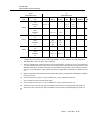
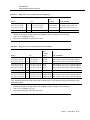
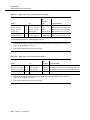
DDM-2000 OC-3 Synchronization
5-34
5-3
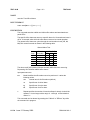
Synchronization Messages using K2 Byte
5-39
5-4
Synchronization Messages using S1 Byte *
5-40
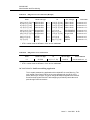
5-5
Available Synchronization References
5-41
Operations Interfaces
6-1
Craft Interface Terminals
6-3
6-2
DDM-2000 OC-3 Pushbutton Combinations
6-11
Circuit Pack Descriptions
7-1
HDSL Line Specifications
7-47
7-2
DDM-2000 OLIU Feature Summary
7-101
7-3
29G-U/29H-U OLIU Specifications
7-152
7-4
29G-U/29H-U OLIU Link Budgets (Notes)
7-153
7-5
Performance Monitoring Parameters Provisionable
via the CIT
7-155
Administration and Provisioning
8-2
Default DS1 to VT1.5 Mapping
8-10
8-3
OI Software Compatibility
8-17
8-8
Ring STS-1 Cross-Connections (Termination/Drop)
(Note)
8-34
Issue 3
June 2001
xxv
Tables
9
8-9
Ring STS-1 Cross-Connections (Hub/Drop)
8-34
8-10
Ring STS-1 Cross-Connections (Pass-Through)
8-35
8-11
Ring STS-1 Cross-Connections
(Drop and Continue)
8-35
8-12
Ring STS-1 Cross-Connections (Hairpin)
8-36
8-13
Ring VT1.5 Cross-Connections (Termination/Drop) 8-36
8-14
Ring VT1.5 Cross-Connections (Hub/Drop)
8-36
8-15
Ring VT1.5 Cross-Connections (OC-1 Hub/Drop)
8-37
8-16
Ring VT1.5 Cross-Connections
(Drop and Continue)
8-37
8-17
Ring VT1.5 Cross-Connections (Pass-Through)
8-38
8-18
Ring VT1.5 Cross-Connections (Locked)
8-38
8-19
Ring VT1.5 Cross Connections (Hairpin)
8-39
8-20
Ring STS-3c Cross Connections
8-39
8-21
Parameters Provisionable via Hardware Switches 8-70
8-22
Parameters Provisionable via the CIT
Maintenance Description
9-1
10
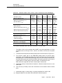
DDM-2000 OC-3 In-Service Software Upgrade
Compatibility (Note)
9-9
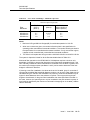
9-2
DDM-2000 OC-3 and OC-12 Software Compatibility
(Note)
9-10
9-3
DDM-2000 OC-3 and DDM-2000 FiberReach
Software Compatibility
9-11
DDM-2000 OC-3 Multiplexer Dual Ring
Interworking Software Compatibility
9-11
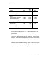
9-5
DS3 Performance Monitoring Enabling
9-53
9-6
DS3 Performance Monitoring (PM) Modes (Note) 9-54
9-4
xxvi
8-71
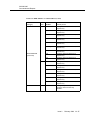
Technical Specifications
Issue 3
10-1
Transmission Interface Standards
10-1
10-2
BBF10 LAN Optical Characteristics
10-10
10-3
DS3 Interface Modes
10-13
10-4
Enhanced DS3 Performance Monitoring Modes
10-13
10-5
22D-U OLIU Specifications
10-27
June 2001
Tables
10-6
22D-U OLIU Link Budgets
10-28
10-7
22F/22F-U/22F2-U and 22G-U/22G2-U/22G3-U
/22G4-U OLIU Specifications
10-30
10-8
22F/22F-U/22F2-U, 22G-U, 22G2-U, 22G3-U, and
22G4-U OLIU Link Budgets
10-31
10-9
OC-3 OLIU Link Budget - Multimode Operation
10-33
10-10
24G-U/24H-U OLIU Specifications
10-34
10-11
24G-U/24H-U OLIU Link Budgets (Notes)
10-35
10-12
26G2-U/27G-U/27G2-U OLIU Specifications
10-37
10-13
26G2-U/27G-U/27G2-U OLIU Link Budgets (Note) 10-38
10-14
26G2-U/27G-U/27G2-U OLIU Link Budgets —
Multimode Operation (Notes)
10-39
10-15
29G-U/29H-U OLIU Specifications
10-40
10-16
29G-U/29H-U OLIU Link Budgets (Notes)
10-41
10-17
OC-3 Rate OLIU Mixes - Minimum Link
Budgets (dB)
10-43
OC-3 Rate OLIU Mixes - Maximum Link Budgets
for SM Fiber (dB)
10-44
OC-3 Rate OLIU Mixes—Maximum Link Budgets
for MM Fiber (dB)
10-46
10-20
Sparing Guidelines
10-48
10-21
Universal Buildout Attenuators
10-51
10-22
DDM-2000 OC-3/OC-1 Transmission Delay in
Microseconds
10-55
10-18
10-19
10-23
Performance Monitoring Parameters Provisionable
via the CIT
10-56
10-24
CIT Interface Pin Connections
10-58
10-25
TL1/X.25 Interface — Default VC Assignments
10-64
10-26
TL1/X.25 Interface — X.25 Packet Layer
Parameters
10-65
10-27
TL1/X.25 Interface — LAPB Link Layer Parameters 10-65
10-28
TL1/X.25 Interface — EIA-232-D Pin Connections 10-66
10-29
Power Dissipation and Current Drains
10-70
10-30
DDM-2000 OC-3 System Reliability Prediction
(Note 1)
10-75
10-31
DDM-2000 OC-3 Circuit Pack Reliability (Note 1)
10-76
10-32
DDM-2000 Fan Shelf Steady State Failure Rates
(Based on Telcordia Technologies RPP,
Issue 6, Data)
10-78
Issue 3
June 2001
xxvii
Tables
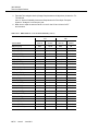
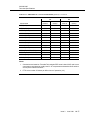
A
A SONET Overview
A-34
xxviii
Issue 3
SONET Transport Rates
June 2001
A-20
About This Document
Purpose
This DDM-2000 OC-3 Multiplexer User/Service Manual, Volume I, covers
Release 15.0 and provides the following:
■
Detailed descriptive information to circuit pack level
■
Technical specifications
■
Commands and reports descriptions.
The DDM-2000 OC-3 Multiplexer User/Service Manual (TOP), Volume II, covers
Release 15.0 and provides operation and maintenance (O&M) task oriented
practice (TOP) supporting acceptance, turnup, and maintenance.
Intended Audiences
This user/service manual is used by training and by the end users responsible for
O&M of the DDM-2000 OC-3 Multiplexer. It may be used by anyone desiring
specific information about the DDM-2000 OC-3 Multiplexer O&M.
Issue 3
June 2001
xxix
363-206-285
About This Document
Reason for Reissue
This document, Issue 2, replaces the DDM-2000 Multiplexer User/Service, Issue
1. Descriptive, application and engineering information has been added for the
DDD-2000 OC-3 Multiplexer through Release 15.0. The release descriptions are
listed in Section 1, "Introduction."
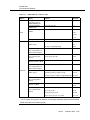
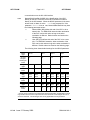
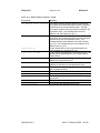
Major changes in this issue are noted by bars (|) in the outermost margins. Major
changes include adding information for the following:
xxx
■
Software Release 15.0 for the DDM-2000 OC-3 Multiplexer
■
Multi-Vendor Interworking with Target ID Address Resolution Protocol
(TARP) for OC-3. See the following page for further information on TARP
and its impact on Operations Interworking
■
Large networks up to 256 nodes using Level 1 provisioning and Level 2
routing
■
STS-3c 0X1 when shelf is equipped with 29G-U/29H-UOLIUs in MAIN slots
and 22-Type OLIUs in FUNCTION UNITS slots
■
STS-1/VT1.5 0X1 when shelf is equipped with 29-Type/24-Type/22-Type
OLIUs in MAIN slots and 22-Type OLIUs in FUNCTION UNITS slots
■
DCC provisioning on MAIN slots for OC-3/OC-12 to allow a remote OC-3
shelf to interconnect through its MAIN ring interfaces with a 1+1 extension
on a host OC-3, OC-12, or OC-48 shelf
■
Provisioning of asynchronous CIT port to run TL1, as well as the
provisioning of the synchronous X.25 port to be used for asynchronous TL1
interface
■
Remote alarm status using AGNE and Alarm Group concept
■
24H-U OLIU 1550 nm long reach OC-12 circuit packs
■
29G-U OLIU 1310 nm long reach OC-12 circuit packs
■
29H-U OLIU 1550 nm long reach OC-12 circuit packs
■
21G3-U OLIU 1310 nm long reach OC-3 circuit packs
■
22G4-U OLIU 1310 nm long reach OC-3 circuit packs
■
BBG2B MXRVO to supply power to BBF6 T1EXT circuit packs in Group 4
or earlier shelves
■
IMA LAN Interface circuit packs: BBF9 LAN 10/100 BaseT and BBF10 100
BaseFX circuit pack
■
BBF4 TG3 Stratum 3 Timing Generator circuit pack (OC-3 and OC-12)
■
BBF2C TGS circuit packs
■
BBF6 T1EXT circuit pack with individual T1 facility loopback capabilities.
Issue 3
June 2001
363-206-285
About This Document
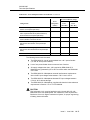
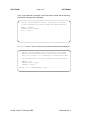
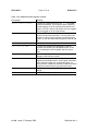
NOTE:
This User/Service Manual covers software releases up to and including
TARP releases R15.0. The impact of introducing TARP will affect many
areas of this document. Be aware that both TARP and the Lucent Directory
Services (LDS) protocol operations are discussed, and that some
operations and features available in pre-TARP releases will no longer be
applicable in Releases 15.0.
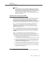
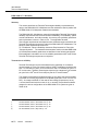
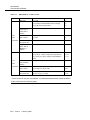
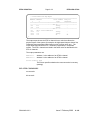
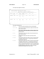
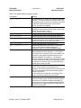
Operations Interworking using TARP
Release 15.0 of the DDM-2000 OC-3 Multiplexer uses Telcordia Technologies’
GR-253 Target ID Address Resolution Protocol (TARP). The Operations
Interworking function provided by TARP offers an alternative to the Lucent
Directory Services protocol (LDS)* but will impact operations in a number of ways.
The following synopsis highlights TARP and its impact on network operations:
Why — Lucent Technologies offers TARP for Operations Interworking as a
standard protocol recommended by Telcordia Technologies for TL1 OS
applications to support interworking with other vendor’s equipment (TARP is
supported by multiple vendors).
When — DDM-2000 OC-3 Releases 15.0 use TARP for OI use (transmission
through non-TARP NEs will not be affected). Future releases of DDM-2000
FiberReach (R4.0), FT-2000 (R9.1), and SLC-2000 (R4.7) will also be TARP
compatible.
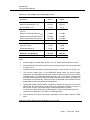
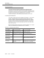
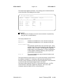
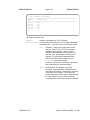
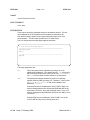
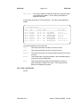
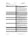
Impact — The following items list some of the areas impacted by the
implementation of TARP. For more detailed information refer to the DDM-2000
OC-3 Release 15.0 Software Release Description , 363-206-231, Issue 1.
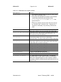
*
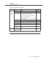
■
Remote alarms are not reported via the DCC using the AGNE and Alarm
Group concept in TARP OC-3 Release 13.x.
TL1/X.25 OS systems will also retrieve remote network alarm information.
■
Remote alarms will be reported via the DCC using the AGNE and Alarm
Group concept in TARP Release 15.0. TL1/X.25 OS systems will also
retrieve remote network alarm information.
■
There will no longer be a DSNE, TBOS, Site, and NE information. TARP
data cache will be maintained by each individual NE for its connectivity.
■
CPro-2000 Release 10.0 and ITM SNC Release 10.0 will support DDM2000 OC-3/OC-12 Releases 15.0.
Release 11.1 and any future non-TARP releases will continue to support LDS.
Issue 3
June 2001
xxxi
363-206-285
About This Document
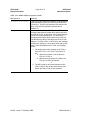
■
Releases 15.0 still support Lucent proprietary applications such as: remote
Craft Interface Terminal (CIT) login, remote software download, and remote
NE to NE automatic time/date synchronization at start-up.
Subnetworks of up to 256 NEs will be supported using subnetwork partitioning
into multiple Level 1 areas.
xxxii
Issue 3
June 2001
363-206-285
About This Document
Safety Instructions
Product Safety Labels
Important safety instructions are in this manual. In addition to the instructions on
the following page, there are other safety instructions you must follow. These
instructions involve lasers, lightwave optical cable and connectors, and
precautions when handling circuit packs to prevent damage from electrostatic
discharge. This manual also contains admonishments in the form of DANGERS,
WARNINGS, and CAUTIONS which must be followed at all times.
These admonishments have the following definitions:
■
DANGER indicates the presence of a hazard that will cause death or
severe personal injury if the hazard is not avoided.
■
WARNING indicates the presence of a hazard that can cause death or
severe personal injury if the hazard is not avoided.
■
CAUTION indicates the presence of a hazard that will or can cause minor
personal injury or property damage if the hazard is not avoided. The
caution is also used for property-damage-only accidents. This includes
equipment damage, loss of software, or service interruption.
Other important safety instructions that you should read are in the "Operation and
Maintenance" section of this manual. Only trained personnel should perform the
procedures in that section.
The alert symbol • appears throughout this product and in this manual to alert the
user to the presence of important operating and maintenance (servicing)
instructions for the DDM-2000 OC-3 Multiplexer.
Lightwave Safety Guidelines
General Laser Information
Lightwave/lightguide systems, their associated test sets, and similar operating
systems use semiconductor laser transmitters that emit light at wavelengths
between approximately 800 nanometers and 1600 nanometers. The emitted light
is above the red end of the visible spectrum, which is normally not visible to the
human eye. Although radiant energy at near-infrared wavelengths is officially
designated invisible, some people can see the shorter wavelength energy even at
power levels several orders of magnitude below any that have been shown to
cause injury to the eye.
Issue 3
June 2001
xxxiii
363-206-285
About This Document
Conventional lasers can produce an intense beam of monochromatic light. The
term monochromaticity means a single wavelength output of pure color that may
be visible or invisible to the eye. A conventional laser produces a small-size beam
of light; and because the beam size is small, the power density (also called
irradiance) is very high. Consequently, lasers and laser products are subject to
federal and applicable state regulations as well as international standards for their
safe operation.
A conventional laser beam expands very little over distance or is said to be very
well collimated. Thus, conventional laser irradiance remains relatively constant
over distance. However, lasers used in lightwave systems have a large beam
divergence, typically 10 to 20 degrees. Here, irradiance obeys the inverse square
law (doubling the distance reduces the irradiance by a factor of 4) and rapidly
decreases over distance.
Lasers and Eye Damage
Light energy emitted by laser and high-radiance LEDs in the 400-1400nm range
may cause eye damage if absorbed by the retina. When a beam of light enters the
eye, the eye magnifies and focuses the energy, magnifying the irradiance. The
irradiance of energy that reaches the retina is approximately10 5 or 100,000 times
that at the cornea, and if sufficiently intense, may cause a retinal burn.
The damage mechanism at the wavelengths used in telecommunications is
thermal in origin (that is, damage caused by heating). Therefore, a specific
amount of energy is required for a definite time to heat an area of retinal tissue.
Damage is not instantaneous. It occurs only when one looks at the light
sufficiently long enough that the product of the retinal irradiance and the viewing
time exceeds the damage threshold. Light energies above 1400 nm would cause
surface and skin burns and do not affect the retinal area.
Classification of Lasers
Manufacturers of lasers and laser products in the United States are regulated by
the Food and Drug Administration's Center for Devices and Radiological Health
(FDA/CDRH) under 21 CFR 1040. These regulations require manufacturers to
certify each laser or laser product as belonging to one of four major Classes —
Class I, II, IIa, IIIa, IIIb, or IV. Lasers are classified according to the accessibly
emission limits and their potential for causing injury. Lightwave systems are
generally classified as Class I, because, under normal operation conditions, all
energized laser transmitting circuit packs are terminated on optical fibers which
enclose the laser energy with fiber sheath, forming a protective housing. Also,
covers are in place over the circuit pack shelves.
xxxiv
Issue 3
June 2001
363-206-285
About This Document
Lightwave Safety Precautions
In its normal operating mode, a lightwave system is totally enclosed and presents
no risk of eye injury. It is a Class I system under the FDA/CDRH scheme.
The lightguide cables that interconnect various components of a lightwave system
can disconnect or break, and may expose people to lightwave emission. Also,
certain measures and maintenance procedures may expose the technician to
emission from the semiconductor laser during installation and servicing. Unlike
more familiar laser devices, such as solid-state and gas lasers, the emission
pattern of a semiconductor laser results in a highly divergent beam. In a divergent
beam, the irradiance (power intensity) decreases rapidly with distance. The
greater the distance, the less energy will enter the eye and the less potential risk
for eye injury.
Inadvertently viewing an unterminated fiber or damaged fiber with the unaided
eye at distances greater than 5 to 6 inches normally will not cause eye injury
provided the power in the fiber is less than a few mW at the shorter wavelengths
and higher at the longer wavelengths. However, damage may occur if an optical
instrument, such as a microscope, magnifying glass, or eye loupe is used to stare
at the energized fiber end.
!
CAUTION:
Use of controls or adjustments, or performance of procedures other than
those specified herein may result in hazardous laser radiation exposure.
Safety Precautions for Enclosed Systems
Under normal operating conditions, lightwave transmission systems are
completely enclosed; nonetheless, the following precautions should be observed:
1.
Because of the potential for eye damage, technicians should neither
disconnect any lightwave cable nor splice and stare into the optical
connectors terminating the cables.
2.
Under no circumstances shall lightwave/lightguide operations be
performed by a technician before satisfactorily completing an approved
training course.
3.
Since viewing lightwave emission directly with an optical instrument, such
as an eye loupe, greatly increases the risk of eye damage, an appropriate
label must appear in plain view on the front of the main frame or lightguide
termination/interconnection equipment. The label shall read as follows:
NOTICE: UNTERMINATED OPTICAL CONNECTORS MAY EMIT
LASER RADIATION. AVOID DIRECT EXPOSURE TO THE BEAM. DO
NOT VIEW THIS BEAM WITH OPICAL INSTRUMENTS.
Issue 3
June 2001
xxxv
363-206-285
About This Document
Safety Precautions for Unenclosed Systems
During service, maintenance, or restoration, a lightwave transmission system is
considered unenclosed. Under these conditions, follow these practices:
1.
Only authorized, trained personnel shall be permitted to do service,
maintenance, and restoration. Avoid exposing the eye to emissions from
unterminated, energized optical connectors at close distances. Connectors
associated with lightwave regenerators are recessed, which limits
exposure distance. However, technicians removing or replacing
regenerators should not stare or look directly into the vacant regenerator
slot with optical instruments or magnifying lenses. (Normal eyewear or
indirect viewing instruments are not considered magnifying lenses or
optical instruments.)
2.
Only authorized, trained personnel shall use the lightwave test equipment
during installation or servicing since this equipment contains
semiconductor lasers. (Some examples of lightguide test equipment are
OTDR's, Hand-Held Loss Test Sets, and Feature Finders.)
3.
Under no circumstances shall any personnel scan a fiber with an optical
test set without verifying that all lightwave sources on the fiber are turned
off.
4.
All unauthorized personnel shall be excluded from the immediate area of
lightwave transmission systems during installation and service.
Consult ANSI* Z136.1 American National Standard for Safe Use of Lasers for
guidance on the safe use of lasers in the workplace.
Electrostatic Discharge (ESD) Considerations
!
CAUTION:
Industry experience has shown that all integrated circuit packs can be
damaged by static electricity that builds up on work surfaces and personnel.
The static charges are produced by various charging effects of movement
and contact with other objects. Dry air allows greater static charges to
accumulate. Higher potentials are measured in areas with low relative
humidity, but potentials high enough to cause damage can occur anywhere.
*
xxxvi
Registered trademark of American Standards Institute, Inc.
Issue 3
June 2001
363-206-285
About This Document
The following precautions should be observed when handling circuit packs in
order to prevent damage by electrostatic discharge:
*
■
Assume all circuit packs contain solid state electronic components that can
be damaged by ESD. Use only Lucent Technologies’ manufactured UL
recognized circuit packs in this system. Recognized circuit packs are listed
in this user/service manual.
■
When handling circuit packs (storing, inserting, removing, etc.) or when
working on the backplane, always wear a grounded wrist strap or wear a
heel strap and stand on a grounded, static-dissipating floor mat. If a staticdissipating floor mat is used, be sure that it is clean.
■
Handle all circuit packs by the faceplate or latch and by the top and bottom
outermost edges. Never touch the components, conductors, or connector
pins.
■
Observe warning labels on bags and cartons. Whenever possible, do not
remove circuit packs from antistatic packaging until ready to insert them
into slots.
■
If possible, open all circuit packs at a static-safe work position, using
properly grounded wrist straps and static-dissipating table mats. If a staticdissipating table mat is used, be sure that it is clean.
■
Always store and transport circuit packs in static-safe packaging. Shielding
is not required unless specified.
■
Keep all static-generating materials, such as food wrappers, plastics, and
Styrofoam* containers, away from all circuit packs. Upon removal from the
bay, immediately put circuit packs into static-safe packages.
■
Whenever possible, maintain relative humidity above 20 percent.
Registered trademark of The Dow Chemical Company.
Issue 3
June 2001
xxxvii
363-206-285
About This Document
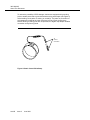
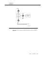
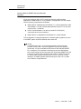
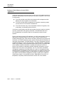
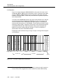
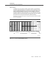
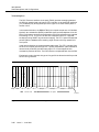
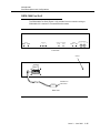
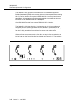
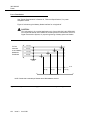
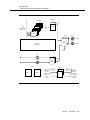
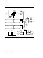
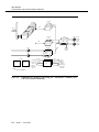
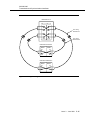
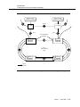
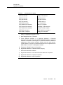
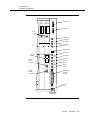
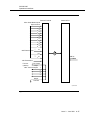
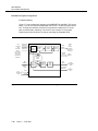
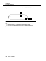
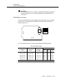
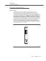
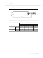
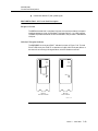
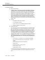
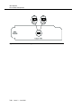
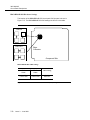
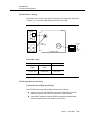
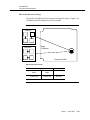
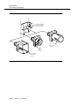
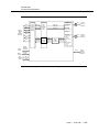
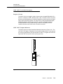
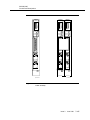
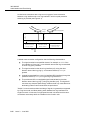
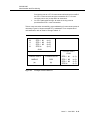
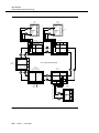
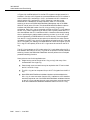
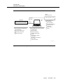
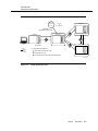
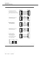
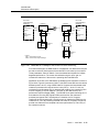
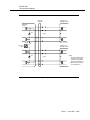
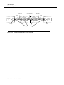
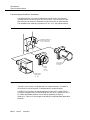
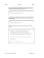
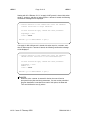
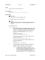
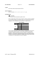
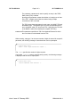
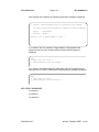
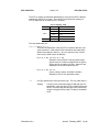
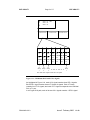
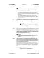
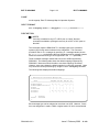
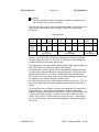
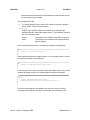
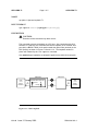
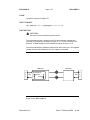
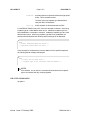
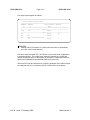
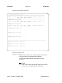
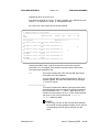
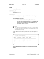
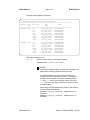
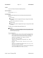
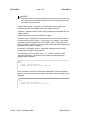
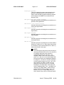
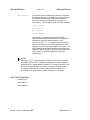
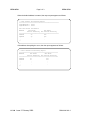
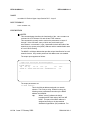
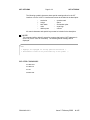
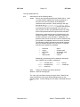
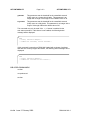
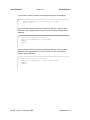
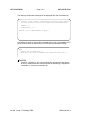
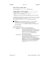
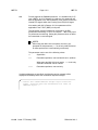
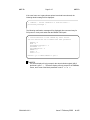
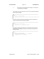
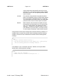
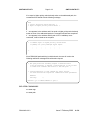
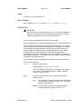
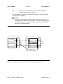
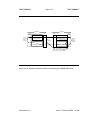
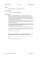
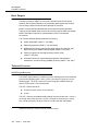
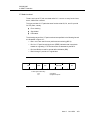
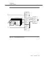
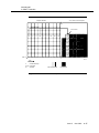
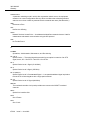
To reduce the possibility of ESD damage, shelves are equipped with grounding
jacks to enable personnel to ground themselves using wrist straps (see Figure A)
while handling circuit packs or working on a shelf(s). The jacks for connection of
wrist straps are located at the lower right-hand corner of each shelf and are
labeled. When grounding jacks are not provided, an alligator clip adapter enables
connection to bay frame ground.
To
Ground
Connection
Figure A. Static Control Wrist Strap
xxxviii
Issue 3
June 2001
363-206-285
About This Document
IMPORTANT SAFETY INSTRUCTIONS
1.
Read and understand all instructions.
2.
Follow all warnings and instructions marked on the product.
3.
Do not place this product on an unstable cart, stand, or table. The product
may fall, causing serious damage to the product.
4.
Slots and openings in this product's back or bottom are provided for
ventilation. To protect it from overheating, these openings must not be
blocked or covered. This product should not be placed in a built-in
installation unless proper ventilation is provided. For information on proper
ventilation requirements, consult the "Equipment Installation
Considerations" section of 363-206-204, DDM-2000 OC-3 Multiplexer
Installation Manual.
5.
This product should be operated only from the type of power source
indicated on the marking label. For information on proper electrical
distribution and power requirements, refer to the "Power" and "Technical
Specifications" sections of this user/service manual.
6.
Never push objects of any kind into this product through cabinet slots as
they may touch dangerous voltage points or short out parts that could
result in a risk of fire or electrical shock. Never spill liquid of any kind on the
product.
7.
To reduce the risk of electrical shock, do not disassemble this product.
Service should be performed by trained personnel only. Opening or
removing covers and/or circuit packs may expose you to dangerous
voltages or other risks. Incorrect reassembly can cause electrical shock
when the unit is subsequently used.
8.
Caution: Disconnect two (2) power connections when removing
power from the system.
9.
Use only Lucent manufactured UL recognized circuit packs in this system.
Recognized circuit packs are listed in this user/service manual.
SAVE THESE INSTRUCTIONS.
Issue 3
June 2001
xxxix
363-206-285
About This Document
IMPORTANT INSTALLATION SAFETY INSTRUCTIONS
1.
Read and understand all instructions.
2.
Installation and maintenance procedures must be followed and performed
by trained personnel only.
3.
All DS1 and DS3 interfaces should not leave the building premises unless
connected to telecommunication devices providing primary or secondary
protection, as applicable.
4.
For information on proper mounting instructions, consult 363-206-204,
DDM-2000 OC-3 Multiplexer Installation Manual.
5.
Never install telecommunication wiring during a lightning storm.
6.
Never install telecommunication connections in wet locations.
7.
Never touch uninsulated telecommunication wires or terminals unless the
telecommunication line has been disconnected at the DS1 or DS3
interface.
8.
Use caution when installing or modifying telecommunication lines.
SAVE THESE INSTRUCTIONS.
xl
Issue 3
June 2001
363-206-285
About This Document
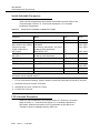
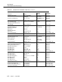
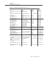
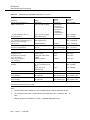
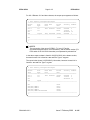
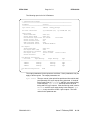
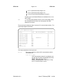
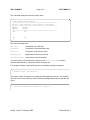
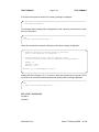
Related Documentation
The following documents provide additional information about the DDM-2000
Multiplexers:
■
Number: 365-576-130 (User Manual only) Release 7.0
Number: 365-576-131 (User Manual & Software) Release 7.0
Title: CPro-2000 User Manual
Audience: Maintenance personnel
Content: Using the tool to provision and maintain ring networks
■
Number: 363-206-200
Title: DDM-2000 OC-3 and OC-12 Multiplexers Applications, Planning, and
Ordering Guide
Audience: Network planners, equipment engineers, and sales teams
Content: Features, applications, high-level description, operations,
administration, maintenance, and provisioning (OAM&P), system planning,
ordering, product support, reliability information, technical specifications,
and a synchronous optical network (SONET) overview.
■
Number: 363-206-201
Title: DDM-2000 OC-3 Multiplexer, System Commands Quick Reference
Audience: Maintenance personnel
Content: Abbreviated list of system commands and parameters for
DDM-2000 OC-3 Multiplexers through Release 7.2
■
Number: 363-206-204
Title: DDM-2000 OC-3 Multiplexer Installation Manual
Audience: Customers planning to install the equipment
Content: Customer installation instructions
■
Number: 363-206-206
Title: DDM-2000 OC-12 Multiplexer — System Commands Quick
Reference
Audience: Maintenance personnel
Content: Abbreviated list of system commands and parameters for
DDM-2000 OC-12 Multiplexers through Release 3.1
■
Number: C107564270
Title: ITM SNC Users Guide
Audience: Operations personnel
Content: Integrated Transport Management Subnetwork Controller
information
Issue 3
June 2001
xli
363-206-285
About This Document
■
Number: 363-206-207
Title: DDM-2000 OC-12 Multiplexer and OC-12 Regenerator User/Service
Manual
Audience: Maintenance personnel
Content: Detailed description, technical specifications, commands and
reports, and O&M procedures for DDM-2000 OC-12 Multiplexers through
Release 3.1 and OC-12 Regenerator through Release 2.0
■
Number: 363-206-208
Title: DDM-2000 OC-12 Multiplexer Installation Manual
Audience: Customers planning to install the equipment
Content: Customer installation instructions
■
Number: 363-206-220
Title: DDM-2000 OC-3/OC-12 Multiplexer Circuit Pack Options Job Aid
Audience: Maintenance personnel
Content: List of circuit pack options
■
Number: 363-206-222
Title: DDM-2000 OC-3/OC-12 Multiplexer Acceptance Task List Job Aid
Audience: Maintenance personnel
Content: Checklist of acceptance and turnup procedures
■
Number: 363-206-223
Title: DDM-2000 OC-12 Regenerator — System Commands Quick
Reference
Audience: Maintenance personnel
Content: Abbreviated list of system commands and parameters
■
Number: 363-206-281
Title: DDM-2000 OC-3 Multiplexer — System Commands Quick Reference
Audience: Maintenance personnel
Content: Abbreviated list of system commands and parameters for
DDM-2000 OC-3 Multiplexers Releases 8.1 and 9.1
■
Number: 363-206-291
Title: DDM-2000 OC-12 Multiplexer — System Commands Quick
Reference
Audience: Maintenance personnel
xlii
Issue 3
June 2001
363-206-285
About This Document
Content: Abbreviated list of system commands and parameters for
DDM-2000 OC-12 Multiplexers Release 5.x
■
Number: 363-206-295
Title: DDM-2000 OC-12 Multiplexer User/Service Manual, Volumes I and II
Audience: Maintenance personnel
Content: Detailed description, technical specifications, commands and
reports (Volume I), and operations and maintenance procedures (Volume
II) for DDM-2000 OC-12 Multiplexer Release 7.0
■
Number: 363-206-300
Title: DDM-2000 FiberReach Multiplexer Applications, Planning, and
Ordering Guide
Audience: Network Planners, equipment engineers, and sales teams
Content: Features, applications, high-level description, operations,
administration, maintenance, and provisioning (OAM&P), system planning,
ordering, product support, reliability information, technical specifications,
and a synchronous optical network (SONET) overview
■
Number: 363-206-305
Title: DDM-2000 FiberReach Multiplexer Wideband/Narrowband TARP
Shelf User/Service Manual
Audience: Maintenance personnel
Content: Detailed description, technical specifications, and O&M
procedures for the DDM-2000 FiberReach Multiplexer Wideband Shelf.
■
Number: 363-206-310
Title: DDM-2000 FiberReach Multiplexer Installation Manual
Audience: Users planning to install the equipment
Content: Customer installation instructions
■
Number: 824-102-144
Title: Lucent Technologies 2000 Product Family Multi-Vendor Operations
Interworking Guide
Audience: System planners and engineers
Content: Operations interworking information for the Lucent Technologies
Product Family 2000 systems, including DDM-2000 Multiplexers and
FT-2000 OC-48 Lightwave Systems in multi-vendor subnetworks
■
Number: 824-102-147
Title: Lucent Technologies 2000 Product Family Operations Interworking
Guide
Issue 3
June 2001
xliii
363-206-285
About This Document
Audience: System planners and engineers l
Content: Operations interworking information for the Lucent Technologies
Product Family 2000 systems, including DDM-2000 Multiplexers and
FT-2000 OC-48 Lightwave System
■
Number: 824-102-151
Title: DDM-2000 Multiplexers Operations Systems Engineering Guide
Audience: Engineers
Content: Operations systems engineering information for the DDM-2000
Multiplexers
■
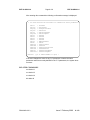
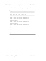
DDM-2000 OC-3 Drawings:
ED-8C724-10 OC-3 and OC-3/OC-12 Combined Bay Arrangements
ED-8C724-15 Cabling Plan (Rear Access)
ED-8C724-16 Cabling Plan (Front Access)
ED-8C724-20 Cable Assemblies
ED-8C724-21 Cable Assemblies
ED-8C724-30 DDM-2000 Shelf Assembly
ED-8C724-31 User Panel Assembly
ED-8C724-42 Release 13 Software Ordering
ED-8C724-43 Release 15 Software Ordering
ED-8C733-30 Fan, Filter, and Baffle Assemblies
SD-7C510-01 Application Schematic
xliv
T7C510-31
Interconnect Wiring (Rear Access)
T7C510-32
Interconnect Wiring (Front Access)
801-525-168
Floor Plan Data Sheets
Issue 3
June 2001
363-206-285
About This Document
■
DDM-2000 OC-12 Drawings:
ED-8C724-10 OC-3 and OC-3/OC-12 Combined Bay Arrangements
ED-8C727-10 Typical Bay Arrangements
ED-8C727-15 Cabling Plan (Rear Access)
ED-8C727-16 Cabling Plan (Front Access)
ED-8C727-20 Cable Assemblies
ED-8C727-21 Cable Assemblies
ED-8C727-30 Shelf Assembly
ED-8C727-31 User Panel Assembly
ED-8C727-37
DDM-2000 OC-12 Release 7 Software Ordering
ED-8C727-41 DDM-2000 OC-12 Regenerator Release 2 Software Ordering
SD-7C513-01 Application Schematic
T7C513-31
Interconnect Wiring Diagram (Rear Access)
T7C513-32
Interconnect Wiring (Front Access)
801-525-168
Floor Plan Data Sheets
DDM-2000 equipment is also available in traditional loop enclosure
arrangements, descriptions of which may be found in the following Lucent
Technologies practices:
■
Number: 363-205-000
Title: SLC® Series 5 Carrier System Ordering Guide — Loop Transmission
Systems (to be replaced by 363-205-010)
■
Number: 363-205-010
Title: SLC® Series 5 System Applications and Planning Guide
■
Number: 363-208-000
Title: SLC®-2000 Access System, Applications, Planning, and Ordering
Guide
■
Number: 363-208-001
Title: SLC®-2000 Access System, User/Service Manual
■
Number: 626-500-105
Title: 80-Type Cabinets Ordering Information and Lettering Guide
Issue 3
June 2001
xlv
363-206-285
About This Document
■
Number: 626-500-115
Title: 90-Type Cabinets Coding and Ordering Information
The following documents provide additional information about related equipment:
■
Number: 365-303-102
Title: DSX-3 Cross-Connect Bay, Description, Operation, and Maintenance
Manual
■
Number: 365-301-130
Title: System III DSX-3/4, Planning, Engineering, Installation, and
Operation — System Reference Guide
■
Number: 365-331-000
Title: DACS III-2000 Release 2.0 Applications, Planning, and Ordering
Guide
■
Number: 365-340-800
Title: DACS IV-2000 Release 5.0 Reference Manual
■
Number: 365-575-100
Title: FT-2000 OC-48 Lightwave System Applications, Planning, and
Ordering Guide
■
Number: 636-299-120
Title: LGXâ Distribution System, Planning, Engineering, Installation, and
Operation System Reference Guide
■
*
xlvi
Title: MegaStar* 2000 Documents
Comcode 107585648
Installation Manual
Comcode 407397512
Schematic Package
Comcode 107585655
Reference Manual
Comcode 107585671
System Application Manual
Registered trademark of Harris Corporation.
Issue 3
June 2001
363-206-285
About This Document
Related Training
The Customer Training and Information Products Centers at Altamonte Springs,
Florida, and Lisle, Illinois, provides management courses for planning,
engineering, and ordering, as well as training for telecommunications technicians
in installation, operations, and maintenance. Suitcasing of these courses is
available. Consult your local Lucent Technologies’ Account Executive for more
information or reservations.
Call 1-888-LUCENT8 (1-888-582-3688), prompt 2 for enrollment.
The following courses are provided by the National Product Training Center:
■
Number: LW2211 (CD-ROM)
Title: DDM-2000 OC-3/OC-12 Multiplexer Fundamentals
Audience: A CD-ROM-based course for anyone interested in learning the
fundamentals of operation of the DDM-2000 OC-3/OC-12 Multiplexers
Content: General information about the DDM-2000 OC-3 and OC-12
Multiplexers including a product overview, applications, and architecture
■
Number: LW2212
Title: DDM-2000 OC-3 and OC-12 Multiplexer Applications and
Architecture
Audience: Fundamental planners, account executives, and private
telecommunications network technical consultants
Content: General information about the DDM-2000 OC-3 and OC-12
Multiplexers including a product overview, applications, architecture, and
deployment planning (a course prerequisite for LW2312)
■
Number: LW2312
Title: DDM-2000 OC-3 and OC-12 Multiplexer Equipment Engineering and
Planning
Audience: Facility planners, outside plant engineers, central office
equipment engineers, and private network design engineers
Prerequisite: LW2212
Content: Information and guidelines required to plan and order DDM-2000
OC-3 and OC-12 Multiplexer equipment for loop feeder and interoffice
applications
Issue 3
June 2001
xlvii
363-206-285
About This Document
■
Number: LW2604
Title: DDM-2000 OC-3 Multiplexer Ring/Linear Networks, Operations and
Maintenance
Audience: Technicians, supervisors, maintenance engineers, and
operation support personnel involved in day-to-day provisioning and
maintenance
Content: Information supporting operations, maintenance, and provisioning
of ring and/or linear DDM-2000 OC-3 Multiplexers. On-site shelves are
used for extensive hands-on experience.
■
Number: LW2610
Title: DDM-2000 FiberReach Wideband Shelf, Operations and
Maintenance
Audience: Technicians, supervisors, maintenance engineers, and
operation support personnel involved in DDM-2000 FiberReach network
functions
Prerequisite: LW2212, LW2312, LW2603, or LW2608
Content: Information supporting operations, maintenance, and provisioning
of DDM-2000 FiberReach Wideband Shelf. On-site shelves are used for
extensive hands-on experience.
■
Number: LW2611
Title: DDM-2000 FiberReach Multiplexer Self-Paced Course
Audience: Technicians, supervisors, maintenance engineers, and
operation support personnel involved in DDM-2000 FiberReach network
functions
Prerequisite: LW2212, LW2312, LW2603, or LW2608
Content: Information supporting system engineering and planning,
applications, operations, maintenance, and provisioning of DDM-2000
FiberReach networks
■
Number: LW2612
Title: DDM-2000 OC-12 Multiplexer Operations and Maintenance
Audience: Technicians, supervisors, maintenance engineers, and
operation support personnel involved in day-to-day provisioning and
maintenance
Content: Information supporting operations, maintenance, and provisioning
of the DDM-2000 OC-12 Multiplexer. Includes information on DDM-2000
OC-12 linear and ring applications. On-site shelves are used for extensive
hands-on experience.
xlviii
Issue 3
June 2001
363-206-285
About This Document
■
Number: LW2614
Title: 2000 Product Family Surveillance and Performance Monitoring
Audience: Technicians, supervisors, maintenance engineers, and
operation support personnel involved in day-to-day provisioning and
maintenance
Content: Information supporting operations interfaces using X.25 links to
an operations center
■
Number: LW2618
Title: Advanced Ring Network Applications, Operations, and Maintenance
Audience: Technicians, supervisors, maintenance engineers, and
operation support personnel involved in day-to-day operations of FT-2000
and/or DDM-2000 OC-3/OC-12 rings having dual ring interworking (DRI)
traffic
Prerequisites: LW2608 and LW2616
Content: Information supporting operations, maintenance, and provisioning
of DRI networks. On-site shelves are used for extensive hands-on
experience.
Issue 3
June 2001
xlix
363-206-285
About This Document
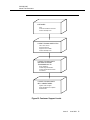
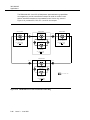
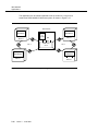
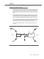
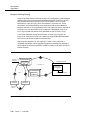
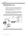
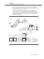
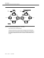
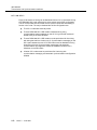
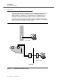
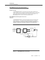
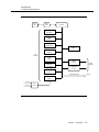
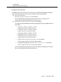
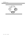
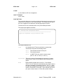
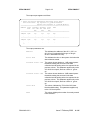
Customer Technical Support (CTS)
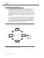
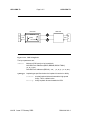
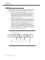
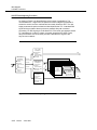
CTS is available through a toll-free technical assistance number. Lucent maintains
a highly-skilled, multi-tier support structure consisting of regional engineers,
product specialists, and system designers to support your network equipment. All
levels of technical expertise may be called upon to solve the customer problem
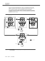
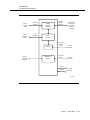
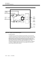
(refer to Figure B).
The CTS organization provides remote, diagnostic support. On-site assistance is
available on a billable contract or time and material basis. Support services may
include the following activities:
■
Responding to all requests for assistance
■
Tracking and maintaining visible ownership of all reported problems, from
inception through resolution
■
Analyzing and diagnosing reported problems
■
Providing restoration and recovery service
■
Providing preventive and/or circumvention measures
■
Communicating the actions, plans, and problem status to the reporting
customer
■
Initiating action to establish Modification Requests (MRs) for design issues
■
Writing and distributing technical bulletins (Urgent Problem Notification).
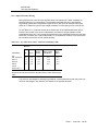
CTS services are available on a contract basis in three levels to meet varying
customer needs: Preferred, Standard, and Basic Agreements. The Preferred level
of support guarantees 24 x 7 (24 hour, 7 day-a-week) coverage of the customer’s
network. Guaranteed performance commitments for response, service
restoration, and problem resolution times are validated by published Service
Performance Reports. The Standard level of support guarantees 8 x 5 (8 hour, 5
day-a-week) coverage. Performance commitments are also validated by Service
Performance Reports. Out-of-hours support is available for an additional fee. The
Basic level of support guarantees 8 x 5 coverage with hourly billing for each
support call. Out-of-hours coverage is available with additional fees.
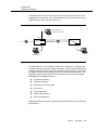
When the customer experiences a problem, the initial point of contact within
Lucent is the Regional Technical Assistance Center (RTAC). RTAC is divided into
three regions covering North America: region East (includes Canada), region
South, and region West. They can be reached by calling 1-800-CAL-RTAC (1-800225-7822). Lucent works with the customer to define the problem and determine
its severity. Problems are worked during the customer’s contracted coverage
period. By prior agreement, service-affecting problems are worked immediately
regardless of contracted coverage with billing reconciliation if required. Acting as a
single point of contact with the customer, the RTAC engineer will involve all
necessary tiers of support to solve the customer problem.
l
Issue 3
June 2001
363-206-285
About This Document
CUSTOMER
Craft
Customer Escalation Procedures
COACH Self-Help Tools
LUCENT TECHNOLOGIES RTAC
First Lucent Contact
Supports Customer
Supports Lucent Installer
COACH Self-Help Tools
LUCENT TECHNOLOGIES
NETWORK SYSTEMS
TRANSMISSION CTS
RTAC Assistance
Problem Diagnosis/Isolation
Provide Solutions/Work Arounds
Consultation
LUCENT TECHNOLOGIES
BELL LABORATORIES
Highest Level of Support
Design Modifications or Updates
Enhancements
Figure B. Customer Support Levels
Issue 3
June 2001
li
363-206-285
About This Document
The following COACH tools are available to the user:
■
Diagnostic Dictionary
The diagnostic dictionary contains histories of previously encountered
problems and descriptions of the solutions or workarounds. Your support
staff can use this tool when published documentation or standard
diagnostic procedures fail to address a problem.
■
News and Bulletins
Immediately after a user logs into COACH, the News and Bulletins tool
displays bulletins containing urgent information related to the user’s
products. All users are automatically notified about urgent matters, such as
problems with scheduled releases, recalls of hardware or software, or
scheduled maintenance for computer support. Less urgent messages are
distributed through news items that can be sent to individuals or categories
of users. Notification of news appears on the screen immediately following
current bulletins.
■
Compatibility Data
Occasionally, hardware/software configuration problems arise when new
software releases are issued. The Compatibility Data tools permit users to
view the correct hardware configuration associated with a specific software
release. The user simply enters the appropriate software release number
and COACH responds with page-formatted lists of circuit packs compatible
with the selected software release. This tool also contains the latest issue
numbers of the customer documentation.
■
COACH User's Guide
COACH supplies an on-line version of its User’s Guide. The COACH
User’s Guide includes instructions on using the customer support tools and
documents any changes to the previous version of the guide.
For information on obtaining a COACH login, contact:
COACH Software Development
Lucent Technologies
1600 Osgood St.
North Andover, MA. 01845
Telephone: 1-800-238-4021
The RTAC and CTS organization strive to provide proactive and responsive
technical customer support for all its products. Through the combined efforts of
the individual customer support groups and through COACH tools, the RTAC and
CTS organization provide the best possible customer support.
lii
Issue 3
June 2001
363-206-285
About This Document
Engineering and Installation Services
The Lucent Technologies Customer Support and Operations (CS&O) organization
provides customers with quality product support services. Whether you need
assistance in engineering, installation, normal system maintenance, or disaster
recovery, the support staff provides you with the quality technical support you
need to get your job done. Each segment of the CS&O organization regards the
customer as its highest priority and understands your obligation to maintain
quality service for your customer.
Within the CS&O organization, the Engineering and Installation Services group
provides a highly skilled force of support personnel to provide customers with
quality engineering and installation services. These engineering and installation
specialists use state-of-the-art technology, equipment, and procedures to provide
customers with highly competent, rapid response services. These services
include analyzing your equipment request, preparing a detailed specification for
manufacturing and installation, creating and maintaining job records, installing the
equipment, and testing and turning over a working system.
When the CS&O organization provides job records and installs the equipment,
operationally affective changes to the system are automatically identified and
applied to the system at no additional cost.
The Engineering and Installation Services group provides the customer with an
individually tailored, quality-tested job that meets our published high standards
and the customer's operational requirements. The group ensures that the
customer's system order is integrated into a complete working system tailored to
office conditions and preferences. This process provides for the customer's
complete needs. It includes provisions for cabling, lighting, power equipment, and
ancillary connections to local and/or remote alarm systems. The group will also
respond to any customer changes that occur during installation.
All equipment engineered and installed by Lucent is thoroughly tested and
integrated into a reliable system at cutover. Once approved by Lucent's Quality
Assurance Test group, the system is turned over to the customer.
The group also provides any specialized engineering and installation services
required for unusual or highly individualized applications. These services may
include engineering consultations and database preparation. Your local Lucent
Technologies’ Account Executive can provide more information about these
services.
Issue 3
June 2001
liii
363-206-285
About This Document
Customer Technical Support Enhanced Services
The goal of Lucent Technologies’ Customer Technical Support Enhanced
Services is to keep Lucent Transmission Systems products operating at maximum
performance and to prevent problems from interrupting service to customers.
Typical Enhanced Services include:
■
Network design, growth planning, and performance analysis
■
Multivendor troubleshooting
■
Network Integration
■
Preventive and remedial maintenance
■
Hardware and software upgrade services
■
On-site maintenance programs
■
Customized MOP (Method of Procedure) development.
For more information on Lucent Technologies’ Customer Technical Support
Services, contact your Lucent Technologies’ Account Executive.
Documentation Support
The Lucent Technologies Customer Training and Information Products
organization provides a contact to report errors or to ask questions about
information in this document. The document support telephone number is
(1-800-645-6759) (Monday through Friday, 8:00 a.m. to
4:00 p.m. EST).
liv
Issue 3
June 2001
363-206-285
About This Document
How to Order Documents
To order additional copies of this document and/or request placement on the
standing order list, send or call in an order as follows:
Telephone Order
Customer
Commercial
Customers *
Mail Order
Lucent Technologies
Customer Information Center
Attention: Order Entry Section
2855 N. Franklin Road
P.O. Box 19901
Indianapolis, IN 46219
(Monday through Friday)
Within USA:
1-888-LUCENT8
1-888-582-3688
7:30 a.m. to 6:30 p.m. EST
FAX: 1-800-566-9568
From Europe, The Middle
East & Africa:
Toll 1-317-322-6416
From Canada, the
Caribbean & Latin America:
Toll 1-317-322-6646
From Asia, the Pacific
Region & China:
Toll 1-317-322-6411
Worldwide:
FAX: 1-317-322-6699
RBOC/BOC
Process through your Company Documentation Coordinator
* For commercial customers, a check, money order, purchase order number,
or charge card number is required with all orders. Make checks payable to
Lucent Technologies.
Lucent entities should use Form IND 1-80.80 FA, available through the
Customer Information Center.
Issue 3
June 2001
lv
363-206-285
About This Document
Standing Orders
One-time orders include a binder (if applicable) and the document contents for the
current issue in effect at the time of order. Also, you may request placement on
the standing order list for all later reissues of the document. The standing order list
for each document provides automatic distribution for all reissues of the
document. RBOC/BOC customers should process document orders or standing
order requests through their Company Documentation Coordinator. For questions
regarding standing orders or to be placed on a standing order list, call the
applicable Lucent Technologies Customer Information Center number listed in
“How to Order Documents.”
How to Comment on This Document
Feedback forms are located immediately after the title page of this document.
Please fill out the form and return it to the address stamped on the front of the
form or fax it to the number provided on the form.
If the feedback forms are missing, send comments on this document to:
Lucent Technologies
Customer Training and Information Products
2400 Reynolda Road
Winston-Salem, NC 27106
You may also report errors or request changes to this document by calling the toll
free number, 1-800-645-6759, and giving the 9-digit document number.
Electronic Documentation
Documentation for the DDM-2000 OC-3 Multiplexer is now available in electronic
form, on compact disk, read-only memory (CD-ROM). CD-ROM has many
advantages over traditional paper documentation, including cost savings, search
and retrieve capability, and the assurance of the most current documentation.
CD-ROM is available by annual subscription (on standing order).
■
lvi
Issue 3
To order, call your Technical Information Resource Manager, your Lucent
Technologies’ Account Executive, or the Lucent Customer Information
Center1-888-LUCENT8 (1-888-582-3688).
June 2001
363-206-285
About This Document
■
For pricing information, contact your Lucent Technologies Network
Systems’ Account Executive or the Lucent Customer Information Center
1-888-LUCENT8 (1-888-582-3688).
The CD-ROM Product Line Order Number for the All Access and Transport
Products Grouping is 300-100-010.
■
For technical information, call Lucent Technologies Documentation Support
(1-800-645-6759).
Issue 3
June 2001
lvii
363-206-285
About This Document
lviii
Issue 3
June 2001
1
System Introduction
Table of Contents
Overview
1-1
Lucent 2000 Product Family
1-1
DDM-2000 Product Family
1-3
Introduction to the DDM-2000 OC-3 Multiplexer
1-5
DDM-2000 OC-3 Multiplexer Releases
1-6
■
Release Descriptions
1-6
DDM-2000 OC-3 Multiplexer
Release 13.0
■
1-16
Release Description
1-16
Issue 3
June 2001
1-i
Table of Contents
1-ii
Issue 3
June 2001
System Introduction
1
Overview
1
1
This section introduces the Lucent Technologies 2000 Product Family and briefly
describes the DDM-2000 OC-3 Multiplexer.
Lucent 2000 Product Family
1
Lucent Technologies is focused on a carefully planned and growing product family
designed to provide total network solutions. The 2000 Product Family complies
with the synchronous optical network (SONET) standard and builds on features
and capabilities that customers have found to be useful and successful in
networks, such as single-ended maintenance features and product upgrade
capabilities. These upgrade capabilities allow a graceful evolution from today's
asynchronous networks to the world-class intelligent networks of the future. The
2000 Product Family provides the significant elements of the Lucent Service Net2000 Architecture.
Lucent's Service Net-2000 Architecture starts with the network as it exists today
and provides real-world solutions to build upon your existing base. It also allows a
graceful evolution from rigid wire centers to a network of flexible nodes. This
network distributes intelligence to where it functions best.
The Service Net-2000 Architecture offers access bandwidth, service on demand,
and self-healing network applications. Access bandwidth offers increased
capacity, giving end-users the ability to access any desired service. This
increased access bandwidth, provided over fiber, offers superior network reliability
while opening up new revenue opportunities.
Service on demand offers high-capacity services implemented in short intervals.
This application gives local exchange carriers the opportunity to generate new
revenue faster by provisioning new services at a competitive "fast start" pace. At
the same time, they help maintain the existing revenue base by increasing
Issue 3
June 2001
1-1
363-206-285
System Introduction
customer satisfaction. Service on demand also reduces start-up costs, thereby
improving capital management.
The self-healing network application involves careful planning and provisioning of
cross-product capabilities with the 2000 Product Family. At the core of this
network is DACS III-2000 and DACS IV-2000 Cross-Connect Systems, the nerve
center of interoffice transmission. The intelligent DACS III-2000 and
DACS IV-2000 Cross-Connect Systems, working with the ITM XM Controller, can
identify failed connections and reroute signals according to a preestablished
recovery plan.
The Lucent 2000 Product Family includes the:
1-2
■
DDM-2000 OC-3 Multiplexer
■
DDM-2000 OC-12 Multiplexer
■
DDM-2000 FiberReach Multiplexer
■
FT-2000 OC-48 Lightwave System
■
DACS III-2000 Cross-Connect System
■
DACS IV-2000 Cross-Connect System
■
■
ITM XM
SLCâ-2000 Access System
■
Business Remote Terminal-2000 (BRT-2000)
■
ITM SNC Sub-Network Controller.
■
CPro-2000
Issue 3
June 2001
363-206-285
System Introduction
DDM-2000 Product Family
1
The DDM-2000 Product Family includes the DDM-2000 OC-3 Multiplexer, the
DDM-2000 OC-12 Multiplexer, the DDM-2000 FiberReach Multiplexer, and
DDM-Plus. The DDM-2000 OC-3 and OC-12 Multiplexers are designed for loop
(access), interoffice (transport), and customer location applications. They start
with many of the proven features of Lucent's DDM-1000 Multiplexer and extend
into the future with the flexibility of the SONET standard. The DDM-2000 OC-3
Multiplexer operates at 51 Mb/s,155 Mb/s or 622 Mb/s, the DDM-2000 OC-12
Multiplexer operates at 622 Mb/s, and the DDM-2000 FiberReach Multiplexer
operates at 51 Mb/s. These multiplexers provide flexible and evolvable network
solutions. With common operations practices and circuit pack reuse, your
investment (for example, technician training, circuit pack inventory) is preserved
as the network evolves to higher capacities and advanced topologies.
The DDM-Plus provides a cost-effective fiber extension from the DDM-1000 or
DDM-2000 Multiplexers transporting one to four DS1s on a fiber pair, either in a
1x1 protected or unprotected configuration.
The DDM-2000 FiberReach Multiplexer is the newest member of the DDM-2000
product family. The DDM-2000 FiberReach Multiplexer is a full-service access
product, combining a 48-line optical network unit with a complete DS1 interface
product. DDM-2000 FiberReach is a SONET product that is "hosted" by either a
DDM-2000 OC-3 Multiplexer or a SLC-2000 Access System. The extension from
the host node is an OC-1 signal in a ring topology. The DDM-2000 FiberReach
Multiplexer operates at 51.84 Mb/s. The DDM-2000 FiberReach Multiplexer can
be used in DDM-Plus applications where increased capacity and interworking
features are needed. See 363-206-300, DDM-2000 FiberReach Applications,
Planning, and Ordering Guide, for more information.
The DDM-2000 OC-3 Multiplexer supports many network topologies, such as
point-to-point, OC-3 fiber hubbing, and linear and ring DS1/DS3/EC-1 add/drop
and OC-1, OC-3, and OC-12 rings with time slot interchange (TSI) in a single 8.5
inch high shelf. Each topology is supported with efficiency and a full complement
of operations features. The DDM-2000 OC-3 Multiplexer provides integrated DS1
to OC-12 multiplexing.
The DDM-2000 OC-12 Multiplexer supports several stand-alone topologies,
including point-to-point, hubbing, add/drop, and ring configurations. The
DDM-2000 OC-12 Multiplexer also supports regenerator applications in balanced
and unbalanced modes.
The DDM-2000 Multiplexers are designed for easy installation and operation.
Centralized operations are supported by a full set of single-ended control and
maintenance features. Integrated test capabilities and default provisioning simplify
installation. Most tasks can be performed using a craft interface terminal (CIT) to
give access to sophisticated provisioning, maintenance and reporting features.
Issue 3
June 2001
1-3
363-206-285
System Introduction
A personal computer (PC) is needed to download software and to run the
CPro-2000 graphical user interface tool software.
In this document, the term "DDM-2000 Multiplexer" is used to reflect the
DDM-2000 OC-3, DDM-2000 OC-12, and DDM-2000 FiberReach Multiplexers.
Since many features, functions, and circuit packs are common among these
multiplexers, information generic to all multiplexers is presented with the
DDM-2000 Multiplexer designation. Information specific to a multiplexer is
described with the DDM-2000 OC-3, DDM-2000 OC-12, or DDM-2000
FiberReach designation, as appropriate.
1-4
Issue 3
June 2001
363-206-285
System Introduction
Introduction to the DDM-2000 OC-3
Multiplexer
1
The DDM-2000 OC-3 Multiplexer is a single shelf SONET digital multiplexer. It is
capable of multiplexing up to 84 DS1 signals, or 3 DS3 signals, or 3 EC-1 signals,
or 6 OC-1 signals, or a combination of DS1, EC-1, and DS3, and OC-1 signals,
into a SONET standard 51.84 Mb/s OC-1, 155.52 Mb/s OC-3 or 622.08 Mb/s
OC-12 signal. The OC-1, OC-3, and OC-12 lines, all transmission-affecting circuit
packs, and the −48 V DC power feeders may be optionally protected. The shelf
can be equipped to serve many diverse network applications and supports a
variety of operations interfaces for current and evolving network operations
needs.
The DDM-2000 OC-3 Multiplexer is designed for loop (access), interoffice
(transport), and customer location applications. The DDM-2000 OC-3 Multiplexer
starts with many of the proven features of Lucent's DDM-1000 multiplexer and
extends into the future with the flexibility of the SONET standard.
A single 8.5-inch high shelf supports a mix of DS1, DS3, OC-1, OC-3, OC-12,
EC-1, OC-3c (STS-3c), and IS-3 signal interfaces, satisfying a wide range of
lightwave terminal and SONET electrical multiplexer applications. It supports
point-to-point, hubbing, DS1/DS3/EC-1 add/drop, STS-1 drop applications, ring
networks and OC-1 extensions.
The DDM-2000 OC-3 Multiplexer is designed for easy installation and operation.
Centralized operation is supported by a full set of single-ended operations (SEO),
control, and maintenance features. Integrated test capabilities and default
provisioning simplifies installation. Some tasks can be performed using faceplate
LED displays and controls, while a CIT gives access to sophisticated
maintenance, provisioning, and reporting features. A PC is needed to download
software and to run CPro-2000 graphical user interface tool software.
Built-in maintenance capabilities support both installation and system operation. A
DDM-2000 OC-3 Multiplexer can be fully tested and installed without external test
equipment.
The DDM-2000 OC-3 Multiplexer has a phased release plan. This manual has
been issued to introduce Release 13.0 and will be updated to cover additional
releases as they become available.
Issue 3
June 2001
1-5
363-206-285
System Introduction
DDM-2000 OC-3 Multiplexer Releases
1
Release Descriptions
1
The following paragraphs provide brief descriptions of the DDM-2000 OC-3
Multiplexer releases.
Release 2 and later features allow additional circuit pack configurations to activate
hubbing and STS-1 linear drop applications. The TL1 message-based interface to
Telecordia Technologies Network Monitoring and Analysis (NMA) operations
system feature comes as part of the controller hardware and software which must
always be furnished separately with Release 2 and later equipment.
Release 3.2 features include two new circuit packs (and associated software): the
22F intermediate reach optical line interface unit (OLIU), which provides full DS1
and DS3 add/drop capability and the BBF2B TGS circuit pack, which provides
DS1 timing outputs. The DS1 timing output is derived from the OC-3 signal.
Release 3 includes a security feature that offers security against unauthorized
access to the CIT system functions. Logins, passwords, and user categories are
provided. Security can be enabled or disabled.
Release 5.1 supersedes Release 5.0 (from this release on, odd feature numbers
are for ring releases while even feature numbers are for linear releases) and is a
two-fiber, virtual tributary (VT) path switched, ring release that requires the use of
22F OLIUs in the Main-1 and Main-2 slots of all shelves in the ring. Time slots
must be reserved all the way around the ring limiting the ring capacity to 84 DS1s.
The ring interfaces include DS1 low-speed, DS3 with STS-1 path protection
switching and cross-connections, EC-1 low-speed with VT1.5 or STS-1 based
cross-connections, or mixed DS1, DS3, and EC-1 interfaces with a total capacity
not exceeding the OC-3 bandwidth.
Release 5.1 features include two new circuit packs (and associated software): the
BBF3 DS1PM which provides DS1 performance monitoring and the BBG6 STS1E
(EC-1) provisioned for low-speed operation. The DS1PM can be mixed with the
DS1 circuit packs in the Low-Speed Group slots. The optional DS1 PM feature
allows measuring of near-end performance and the extended superframe (ESF)
far-end performance report of the incoming DS1 signal. This allows the service
provider to determine the end-to-end performance of the DS1 signal. SONET
synchronization messaging is used to communicate the quality of network timing,
internal timing status, and timing states throughout a subnetwork.
1-6
Issue 3
June 2001
363-206-285
System Introduction
Release 6.0 supports linear applications with new features that include OC-3/
OC-12 interworking using the open systems interconnection (OSI) 7-layer
protocol stack over the data communications channel (DCC). The OSI 7-layer
protocol stack refers to the OSI reference model, a logical structure for network
operations standardized by the international standards organization (ISO). This
OC-3c transport feature is used to interface with broadband terminals.
Release 6.0 includes one new circuit pack (and associated software): the BBG6
STS1E which provides a high-speed or low-speed EC-1 interface. The STS1E
circuit packs are used in the Function Unit slots for EC-1 electrical multiplexer
(high-speed) or EC-1 low-speed applications. The optional VT1.5 performance
monitoring (PM) feature provides the PM of the V5 byte for errored seconds (ES),
severely errored seconds (SES), and unavailable seconds (UAS). The optional
DS1 PM feature allows measuring of near-end performance and the ESF far-end
performance report of the incoming DS1 signal. This allows the service provider to
determine the end-to-end performance of the DS1 signal. Enhanced security
features include additional logins. The TL1 message-based interface, introduced
in Release 2.0 and enhanced in subsequent releases, for centralized surveillance
by NMA systems is enhanced in this release to allow Telcordia’s OPS/INE system
to provide centralized flow through provisioning of ports and cross-connections.
Release 6.2 replaces Release 6.1 and includes linear optical extensions from an
OC-3 ring and an automatic synchronization reconfiguration feature. Automatic
synchronization reconfiguration provides the ability to automatically select another
synchronization source and to automatically reconfigure the synchronization
provisioning in the event of a synchronization source failure or a synchronization
change in the network, for example, a fiber cut. The feature can be enabled or
disabled. Additional TL1 messages support provisioning, maintenance, testing,
PM, and security functions.
Release 6.2 includes SLC-2000 Release 3.1 and 3.2 interworking and channel
state provisioning. Channel state provisioning is a capability provided on
DDM-2000 Multiplexers that suppresses reporting of alarms and events during
provisioning by supporting multiple states (automatic, in-service, and notmonitored) for VT1.5 and STS-1 channels.
Release 7.0 is an enhanced ring release. Release 7.0 supports a "drop and
continue" feature which is used with DRI applications and an automatic
synchronization reconfiguration feature. Release 7.0 features include two new
plug-ins (and associated software): the 22D-U and the 22G-U OLIUs. The 22D-U
OLIU provides a short-reach IS-3 with TSI optical interface between colocated
OC-3 and OC-12 and SLC-2000 ring shelves. The 22G-U OLIU has the same
functionality of the 22F OLIU but with a 23 dB outside plant loss budget allowing
for spans of up to 51 km. The 22D-U and 22G-U OLIUs support signal degrade
protection switching. The "U" designation for the 22D-U and 22G-U OLIUs means
the OLIUs have universal optical connectors. These OLIUs have adapters that
allow the use of ST â, SC, or FC connectors on the faceplates. The 22D-U and
Issue 3
June 2001
1-7
363-206-285
System Introduction
22G-U OLIUs can be used in all releases that currently support 22F OLIUs
(Release 3.1 and later).
Release 7.1 is an enhanced ring release featuring interworking with an OC-12
ring and interworking with SLC-2000 Release 3.1 and 3.2 in a ring. Release 7.1’s
new features include channel state provisioning, STS-1 signal degrade protection
switching, OC-12 VT1.5 path switched ring (ring 0x1 low-speed interface) optical
interconnections between DDM-2000 OC-3 and OC-12 ring shelves (OC-3/IS-3),
enhanced DS3 PM, and additional TL1 commands and enhancements.
Channel state provisioning is a capability provided on DDM-2000 OC-3 and
OC-12 Multiplexers that suppresses reporting of alarms and events during
provisioning by supporting multiple states (automatic, in-service, and notmonitored) for VT1.5 and STS-1 channels. The STS-1 signal degrade feature
requires the 22G-U or 22D-U OLIUs and measures the BIP-8 (B3) parity
violations and causes a protection switch to the alternate path if the provisioned
bit error rate threshold is crossed. The OC-12 VT1.5 path switched ring (ring 0x1
low-speed interface) OC-3/IS-3 interface offers a significant advantage over the
1+1 protected OC-3/IS-3 interface for VT1.5 path switched ring applications. Ring
(0x1) low-speed interface means two service lines (no protection lines) are used
between the OC-12 Multiplexer ring and the OC-3 Multiplexer ring. Switching is
not done on the DDM-2000 OC-12 Multiplexer; rather VT1.5 or STS-1 level
switching is done at the DDM-2000 OC-3 Multiplexer.
Enhanced DS3 PM provides a collection (from the fiber or high-speed interface) of
the DS3 parity-bit (P-Bit) and frame and multiframe (F&M) bit ES, SES, and UAS
to the already provided coding violations and severely errored frame seconds
(SESF). The feature is mainly used for DS3 tariff verification.
Release 7.2 is a ring release that provides OC-3 operations interworking with the
FT-2000 OC-48 Lightwave System. It also allows interworking between the old
controllers (BBG5 and BBG7) and the new controllers (BBG8/BBG8B and BBG9).
DDM-2000 FiberReach (OC-1) extensions can be added to Release 7.1 rings by
upgrading the rings to Release 7.2 and adding a Release 9.0 OC-3 host node.
Only OC-3 DDM-2000 FiberReach host nodes need Release 9.0 software and the
new controllers.
■
New applications:
— OC-3 operations interworking with FT-2000 OC-48 Lightwave
System. Single-ended operations and DCC connectivity supported
over OC-3 interfaces. Requires FT-2000 OC-48 Lightwave System
Release 6.0 software.
— OC-3/IS-3 DRI with VT1.5/STS-1 drop and continue. Single-ended
operations and DCC connectivity between DDM-2000 systems or
DDM-2000 and FT-2000 OC-48 Lightwave Systems in DRI
applications.
— Increased network size. A DDM-2000/SLC-2000/FT-2000 OC-48
Lightwave System subnetwork of 24 network elements (NE).
1-8
Issue 3
June 2001
363-206-285
System Introduction
■
New features:
— Multiple OS Gateway Network Element (GNE). In DDM-2000/
SLC-2000 networks, more than one NE can be physically connected
to X.25 allowing OSs to automatically select an alternate GNE in
case of primary GNE failure. The feature also allows different GNEs
to support different OSs simultaneously.
— Provisionable X.25 packet size of 128 or 256 bytes.
— Enhanced PM. Enhancements to DS1 and DS3 line and path PM to
further support tariff verification. Enhanced DS3 PM requires the
new BBG4B DS3 circuit pack.
— CPro-2000 R3.0, 4.0, 5.0, and 6.0.
Release 8.0 is a linear release using the new BBG8/BBG8B system controller and
BBG9 overhead controller circuit packs.
■
New applications:
— OC-3 operations interworking with FT-2000 OC-48 Lightwave
System. Single-ended operations and DCC connectivity supported
over OC-3 interfaces. Requires FT-2000 OC-48 Lightwave System
Release 6.0 software.
— OC-3/IS-3 linear extensions from OC-12 rings. 1+1 linear OC-3 and
IS-3 extensions from OC-12 rings.
— Increased subnetwork sizes. A DDM-2000/SLC-2000 subnetwork of
32 NEs. A mixed DDM-2000/SLC-2000/FT-2000 OC-48 Lightwave
System/OC-3 Release 7.2 subnetwork of 24 to 32 NEs.
■
New features:
— Multiple Operations System (OS) Gateway Network Element (GNE).
In DDM-2000/SLC-2000 networks, more than one NE can be
physically connected to X.25 allowing OSs to automatically select
an alternate GNE in case of primary GNE failure. The feature also
allows different GNEs to support different OSs simultaneously.
— Additional X.25 switched virtual circuits. Nine virtual circuits can be
provisioned in any combination of switched and permanent virtual
circuits for connections to OSs.
— Provisionable X.25 packet size of 128 or 256 bytes.
— Centralized operations over X.25 link. DDM-2000 CIT commands
have equivalent TL1 commands. This allows centralized operations
of DDM-2000 systems via the TL1/X.25 link as an alternative to CIT
commands.
Issue 3
June 2001
1-9
363-206-285
System Introduction
— New controllers. The new BBG8/BBG8B and BBG9 controller circuit
packs provide expanded memory and processing capacity needed
to support large networks. Feature enhancements available with the
new controllers include:
— Remote software download. Software can be downloaded
from a PC connected to a DDM-2000/SLC-2000 NE to either
the local or remote DDM-2000/SLC-2000 NE.
— Electronic provisioning. Provisionable parameters are set by
software, thus decreasing the need for DIP switches. CIT
baud rate is provisioned automatically via autobaud
detection.
— User-assigned RT miscellaneous discretes increased from
15 to 21.
— Upgrades to the new controllers can be done in service.
— Enhanced PM. Enhancements to DS1 and DS3 line and path PM to
further support tariff verification. Enhanced DS3 PM requires the
new BBG4B DS3 circuit pack.
— Enhanced security. General and reports-only users increased from
50 to 100. Lockout of nonpriviliged users and log of all login
attempts is provided.
— Electrical facility loopbacks. DS1, DS3, and EC-1 equipment
loopbacks of the incoming low-speed signal back towards the DSX.
— STS path trace. Provided in the J1 byte of the SONET path
overhead to verify STS path continuity. Allows "labeling" of STS-1s
and retrieval of the path by the "label." For example, "ABC #1." STS
path trace requires the new BBG4B DS3 circuit pack.
— Provisionable AIS or unequipped conditions. Path AIS provisionable
on a path basis. Provides user provisionable generation of AIS or
path unequipped signal on a per-shelf basis. Useful in managing
cross-connection provisioning if cross-connections are inadvertently
deleted.
— Provisionable line and path AIS alarm levels. Alarm levels can be
provisioned on a per-line or per-path basis.
— Brownout protection. If the voltage to the shelf drops below the safe
operating voltage, the system will suspend normal operations and
wait for safe operating voltage to return. Assuming a sufficient
voltage level, an "L" will be displayed on the system controller
(SYSCTL).
1-10
Issue 3
June 2001
363-206-285
System Introduction
— SYSCTL optical faceplate latch. An optical switch on the BBG8/
BBG8B SYSCTL circuit pack latch causes a suspension of
controller operations and an "F" to be displayed on the controller
panel display when the latch is pulled. Closing the latch causes a
controller reset.
— CPro-2000, ITM SNC. Release 8.0 is supported by
CPro-2000 Releases 4.0, 5.0, and 6.0, and ITM SNC Release 2.1.
Release 8.1 is a linear release supporting MegaStar* 2000 SONET Radio.
Release 8.1 requires the BBG8/BBG8B SYSCTL system controller and BBG9 or
new BBG10 OHCTL overhead controller. Release 8.1 may be used for nonMegaStar 2000 applications when S1 byte synchronization messaging is desired.
Release 8.1 will interwork with Releases 7.2 or 9.0.
■
New Applications:
— MegaStar 2000 SONET Radio. Part of Lucent Technologies and
Harris-Farinon MegaStar 2000 Radio system supporting mixed fiber
and radio topologies. MegaStar applications require the BBG10
OHCTL.
■
New Features:
— S1 Byte synchronization messaging. Uses the S1 byte of the
SONET overhead to pass timing status information to different
nodes in a loop-timed network. Synchronization messaging mode
(S1 byte or K2 byte) is provisionable on a per OC-N basis.
— CPro-2000, ITM SNC. Release 8.1 is supported by
CPro-2000 Releases 5.0, 6.0, and ITM SNC Release 4.0.
Release 9.0 provides all of the features of Release 7.2 and is a ring release using
the new BBG8/BBG8B system controller and BBG9 overhead controller circuit
packs.
■
New applications:
— OC-3 DDM-2000 FiberReach host. An OC-3 shelf equipped with
27G-U dual OC-1 OLIUs that supports OC-1 ring extensions from an
OC-3 ring, linear, or stand-alone network.
— Automatic synchronization reconfiguration of timing from both Main
and Function Unit C slots.
— Increased subnetwork sizes. A DDM-2000/SLC-2000 subnetwork of
32 NEs. A mixed DDM-2000/SLC-2000/FT-2000 OC-48 Lightwave
System/OC-3 Release 7.2 subnetwork of 24 to 32 NEs.
*
MegaStar is a registered trademark of Harris Corporation.
Issue 3
June 2001
1-11
363-206-285
System Introduction
— VT hairpin. Cross-connections are allowed between Function Unit A
to Function Unit C and Function Unit B to Function Unit C. Optical
extensions from Function Unit A slots are also allowed.
— Dual homing. Ring (0x1) low-speed interface cross-connections
between Main and Function Unit slots for dual homing applications
between DDM-2000 OC-3 Multiplexers and DDM-2000 FiberReach.
— Locked cross-connections. Ring (0x1) low-speed interface or VT
locked cross-connections between low-speed and high-speed time
slots, locking ring traffic onto a designated ring rotation. Used in
utility market applications.
■
New features:
— Additional X.25 switched virtual circuits. Nine virtual circuits can be
provisioned in any combination of switched and permanent virtual
circuits for connections to OSs.
— Centralized operations over X.25 link. DDM-2000 CIT commands
have equivalent TL1 commands. This allows centralized operations
of DDM-2000 systems via the TL1/X.25 link as an alternative to CIT
commands.
— New controllers. The new BBG8/BBG8B and BBG9 controller circuit
packs provide expanded memory and processing capacity needed
to support large networks. Feature enhancements available with the
new controllers include:
— Remote software download. Software can be downloaded
from a PC connected to a DDM-2000/SLC-2000 network
element to either the local or remote DDM-2000/SLC-2000
NE.
— Electronic provisioning. Provisionable parameters are set by
software, thus decreasing the need for DIP switches. CIT
baud rate is provisioned automatically via autobaud
detection.
— User-assigned RT miscellaneous discretes increased from
15 to 21.
— Upgrades to the new controllers can be done in service.
— Enhanced PM. Enhancements to DS1 and DS3 line and path PM to
further support tariff verification. Enhanced DS3 PM requires the
new BBG4B DS3 circuit pack.
— Enhanced security. General and reports-only users increased from
50 to 100. Lockout of nonpriviliged users and log of all login
attempts provided.
— Electrical facility loopbacks. DS3, and EC-1 equipment loopbacks of
the incoming low-speed signal back towards the DSX.
1-12
Issue 3
June 2001
363-206-285
System Introduction
— STS path trace. Provided in the J1 byte of the SONET path
overhead to verify STS path continuity. Allows "labeling" of STS-1s
and retrieval of the path by the "label." For example, "ABC #1." STS
path trace requires the new BBG4B DS3 circuit pack.
— Provisionable AIS or unequipped conditions. Path AIS provisionable
on a path basis. Provides user provisionable generation of AIS or
path unequipped signal on a per-shelf basis. Useful in managing
cross-connection provisioning if cross-connections are inadvertently
deleted.
— Provisionable line and path AIS alarm levels. Alarm levels can be
provisioned on a per-line or per-path basis.
— OC-1 line state provisioning. A capability provided on DDM-2000
OC-3 Multiplexers that suppresses reporting of alarms and events
by supporting multiple states (in-service and not monitored) for OC1 lines.
— Brownout protection. If the voltage to the shelf drops below the safe
operating voltage, the system will suspend normal operations and
wait for safe operating voltage to return. Assuming an insufficient
voltage level, an "L" will be displayed on the SYSCTL.
— SYSCTL optical faceplate latch. An optical switch on the BBG8/
BBG8B SYSCTL circuit pack latch causes a suspension of
controller operations and an "F" to be displayed on the controller
panel display when the latch is pulled. Closing the latch causes a
controller reset.
Release 9.1 is a ring release which provides all the features of Release 9.0 and
requires the BBG8/BBG8B and BBG9 or BBG10 controller hardware. In addition,
Release 9.1 supports the following applications and features:
■
New Applications:
— MegaStar 2000 SONET Radio. Part of Lucent Technologies and
Harris-Farinon MegaStar 2000 Radio system supporting mixed fiber
and radio topologies. MegaStar 2000 applications require BBG10
OHCTL.
— Extended FiberReach topologies. Using the new 27G2-U OLIU and
Release 2.0 or 2.1 of FiberReach, Release 9.1 supports:
■
Hairpin single and dual 0x1 cross-connects between OC-1s
within the same 27G2-U OLIU.
■
Hairpin single and dual 0x1 cross-connects between 27G2-U
OLIUs in different function units.
■
Pass-through cross-connects for an OC-1 ring terminated on
27G2-U OLIUs in a function unit.
■
Mixing of all supported cross-connect types.
Issue 3
June 2001
1-13
363-206-285
System Introduction
■
New Features:
— S1-byte Synchronization Messaging. Uses the S1 byte of the
SONET overhead to pass timing status information to different
nodes in a loop-timed network. Synchronization messaging mode
(S1 byte or K2 byte) is provisionable on a per-OC-3 basis.
— Enhanced DS1 PM. Provides 15 minute bins for DS1 path and line
PM data.
— Fourth Level of Security. A new Maintenance security level, which
allows access to Reports and some maintenance activities is
provided in addition to the three current levels of privileged, general,
and reports-only.
— Quad-DS1 electrical loopbacks. Provides an electrical facility
loopback of four DS1 interfaces from a given BBF1B or BBF3 DS1
circuit pack.
— Large networks. Supports DDM-2000 and FiberReach networks of
up to 50 nodes.
— CPro-2000, ITM SNC support. Release 9.1 is supported by
CPro-2000 Releases 5.0 and 6.0, and ITM SNC Releases 2.2
and 4.0.
— 27G2-U OLIU. The new 27G2-U OLIU supports the new crossconnects necessary to provide enhanced FiberReach topologies.
Release 11.0 is an enhanced ring release which provides all the features of
Release 9.1. In addition, Release 11.0 supports the following applications and
features:
■
New Applications:
— OC-12 high-speed optics for OC-3 shelf. Increases ring capacity by
providing low-speed DS1 and FiberReach services directly from an
OC-12 ring via the OC-3 shelf. Minimizes need for back-to-back
equipment. Supports mixing of OC-3 and OC-12 shelves on the
same ring during upgrades.
— Enhanced FiberReach topologies. Supports a hairpin local drop of
traffic from an OC-1 ring terminated on 27G2-U OLIUs in a function
unit to a DS1/EC-1/OC-3 interface in the other function unit group.
The 27G2-U is required for these applications. Release 11.0 also
supports mixing of local drop, pass-through, and 0x1 cross-connect
types.
— Multi-media Data Services: A new DS3 interface provides the
flexibility to offer a full range of multi-media data services via
embedded and new DDM-2000 networks. This full-solution offering
1-14
Issue 3
June 2001
363-206-285
System Introduction
is made possible by interfacing DDM-2000 to any of the numerous
commercially available data edge devices which provide the various
data services interfaces.
— Native Mode LAN Interface. By deploying DDM-2000 with an
adjunct LAN router/ATM switch, Release 11.0 provides a Native
Mode LAN Interface. DDM-2000 offers up to 4 LAN ports per STS-1
of bandwidth. Point-to-point and point-to-multi-point service is
provided. In a later release, this functionality will be integrated
directly in the DDM-2000 shelf.
■
New Features:
— New OC-12 OLIU (24G-U) for OC-3 shelf. The new 24G-U OLIU
provides OC-12 optics directly from the DDM-2000 OC-3 shelf. This
allows the OC-3 shelf to support an OC-12 ring, with the low-speed
inputs and capacity of the OC-3 shelf. The 24G-U OLIU provides
visibility to the full STS-12 bandwidth and allows for selection of any
traffic from any 3 STS-1s on the OC-12 ring for drop at the OC-3
shelf. Remaining traffic can be passed-through on the OC-12 ring.
— Data Services Interface. A new DS3 circuit pack and cross-connect
software provide the DDM-2000 interface to an external LAN router/
ATM switch for providing Native Mode LAN or general data services
via the SONET network.
— Enhanced Software Download. The software upgrade from Release
9.1 to 11.0 and later releases provides a software installation or
copy capability which allows compressed files containing the new
software generic to be downloaded—locally or remotely—to the
DDM-2000 system while the current version is still running. This
enhancement reduces both the time the controller is unavailable
and the time to download the software. When the appropriate
command is initiated, the new generic is installed. Installation of the
new generic can be scheduled, allowing coordination of cutover of
several NEs in the subnetwork.
— CPro-2000, ITM SNC support. Release 11.0 is supported by:
CPro-2000 Release 6.0 and ITM SNC Release 4.0.
— Frequency error monitoring. STS pointer justification performance
monitoring and thresholding provide a means to detect frequency
errors in the synchronization network.
Issue 3
June 2001
1-15
363-206-285
System Introduction
DDM-2000 OC-3 Multiplexer
Release 13.0
1
Release Description
1
NOTE:
DDM-2000 OC-3 Release 13.0 is NOT compatible with previous releases of
DDM-2000 OC-3. Therefore, when upgrading a subnetwork, care should be
taken to avoid isolating NEs that have not yet been upgraded to Release
13.0.
The following paragraphs provides a brief description of the DDM-2000 OC-3
Multiplexer Release 13.0.
Release 13.0 is an enhanced ring release which provides all the transmission
features of previous DDM-2000 releases. In addition, Release 13.0 supports the
following applications and features:
■
New Applications:
— Enhanced FiberReach topologies. Supports enhanced routing with
the single OC-1 26G2-U OLIU. The 26G2-U, with built-in multiplexer
capabilities, can drop DS1s without the need for the MXRVO
Multiplexer or BBF5 Jumper circuit packs. The 26G2-U provides
OC-1 ring pass-through, OC-1 ring hairpin single-homed and dualhomed, and OC-1 ring hairpin local drop applications.
— Transmultiplexer DS3 path termination. The new TMUX circuit pack
(BBG20) provides path termination functions for an M13 or C-bit
parity DS3 signal. It demultiplexes the DS3 into 28 DS1s, performs
DS1 PM, maps each DS1 into a VT1.5, and multiplexes the 28
VT1.5s into an STS-1.
— High bit rate Digital Subscriber Line (HDSL). The HDSL circuit pack
(BBF8) provides HDSL interface capability on the DDM-2000 OC-3
shelf. It allows the transport of T1 payloads, for up to 12,000 feet,
over two metallic 24 AWG twisted-pair lines.*
— Interworking with Tellabs TITAN † 5500/S Release 5.0 Digital
Cross-Connect System.
*
†
1-16
The HDSL circuit pack can also be installed in DDM-2000 OC-3 shelves running linear
Releases 6.2 and later, and ring Releases 7.1 and later. Refer to information included with
each circuit pack for provisioning instructions.
TITAN is a trademark of Tellabs, Inc.
Issue 3
June 2001
363-206-285
System Introduction
■
New Features:
— Multi-Vendor Operations Interworking (OI) compatibility.
■
DDM-2000 is compatible with any other-vendor NEs that
support Target ID Address Resolution (TARP) protocol, OSI
on the DCC, IAO LAN, and TL1/X.25 as specified in Telcordia
GR-253.
■
Compatible with Tellabs TITAN 5500/S Release 5.0 Digital
Cross-Connect System, including TL1/X.25 OS access with
TITAN serving as the TL1/X.25 GNE.
— Lucent 2000 Product Family OI compatibility.
■
Compatible with DDM-2000 OC-12 R7.0, FiberReach R3.0,
and FT-2000 R8.0 (but not with earlier releases due to multivendor OI support).
■
DDM-2000 OC-3 R13.0 can serve as the TL1/X.25 GNE for
FT-2000 R8.0 remote NEs.
— Large subnetworks.
■
Supports large subnetworks of up to 256 NEs by partitioning
into multiple areas connected via Level 2 Intermediate
Systems (ISs).
— IntrAOffice LAN (IAO LAN).
■
Provides an extension of the SONET DCC for operations
data communications. All NE-to-NE features supported over
the DCC are supported over the IAO LAN.
■
Supports ITM SNC software download to DDM-2000*
■
Supports ITM SNC as the TL1-GNE for DDM-2000.
— Stratum 3 timing generator circuit pack (BBF4).† The TG3 operates
with an internal oscillator of ±4.6 ppm long term accuracy.
— STS-1 hairpin cross-connection.
— Single DS1 facility loopback using the BBF3B circuit pack.
— Intermediate node STS performance monitoring. This feature
collects, reports, and thresholds PM status for the SONET STS-1
Path (B3) derived parameters at intermediate Network Element
interfaces.
*
†
This feature will be useful when upgrading from DDM-2000 OC-3 R13.0 to later releases.
Available third quarter 1998 for use with Release 13.0 and later.
Issue 3
June 2001
1-17
363-206-285
System Introduction
— Alarm severity escalation. Allows the user to provision (enable/
disable) the alarming of service affecting/non-service affecting
entities.
— CPro-2000, ITM SNC support. Release 13.0 is supported by:
CPro-2000 Release 7.0; ITM SNC Release 5.0 (supports enhanced
database backup and restore capabilities).
— Reports all active users through the DCC and X.25.
— Default TID. The default Target Identifier (TID) for R13.0 is LT-DDM2000, instead of the previous default of Site#NE#.
— TL1 commands:
— RTRV-CID-SECU (also new CIT command RTRV-SECU) to
report the active user logins.
— RTRV-LOG to report the 500 most recent events in the
history log (equivalent to existing CIT command RTRVHSTY).
— ENT-FECOM to provision DCC user-side/network-side
settings and to enable or disable remote access via each
DCC (equivalent to existing CIT command SET-FECOM
which is now supported via CIT remote login and OS).
— RTRV-FECOM to report the provisioned state of each DCC
(equivalent to existing CIT command RTRV-FECOM).
Release 15.0 is an enhanced ring release which provides all the transmission
features of Release 13.0. In addition, Release 15.0 supports the following
applications and features:
■
New Applications:
— IMA LAN Interface. With the introduction of a new low-speed circuit
pack, Release 15.0 provides a direct IMA LAN to WAN interface
through the DDM-2000 OC-3.
■
The IMA LAN (BBF9 metallic or BBF10 optical) circuit pack
provides an interface for one 10/100BaseT, 100BaseFX IEEE
802.3 standard compliant interface.
— T1 Interface. The T1EXT (BBF6) circuit pack provides line
termination for two bi-directional T1 line interfaces. Signals received
from the T1 interface are mapped into SONET VT1.5 signals. The
resulting signals are routed to the OLIU circuit packs. The T1EXT
circuit pack is used only with the enhanced MXRVO (BBG2B) circuit
pack in Groups 3 and 4 shelves. This can also be used in Group 3
shelves per C8854. Requires separate secondary lightning and
surge protection in outside plant applications.
1-18
Issue 3
June 2001
363-206-285
System Introduction
— STS-3c 0x1 Configuration. This application provides the ability of
transporting STS-3c services on OC-3c low speed FUNCTION
UNITS optical interfaces that have been provisioned for 0x1 with
29G-U/29H-U OLIUs in MAIN and 22-Type OLIUs in FUNCTION
UNITS slots. STS-3c routing is restricted to FUNCTION UNITS C.
— STS-1/VT1.5 0x1 Configuration. This application provides the ability
of transporting STS-1 services on OC-3 low speed FUNCTION
UNITS optical interfaces that have been provisioned for 0x1 with 29/
24/22-Type OLIUs in MAIN and 22-Type OLIUs in FUNCTION
UNITS slots of the host OC-3 shelf.
■
New Features:
— Support the OC-12 optics through the 29G-U/29H-U OLIU circuit
packs in the Main Unit slots. The related features are as follows.
■
STS-1/STS-3c/VT1.5 pass-through cross-connections on the
29G-U/29H-U OC-3 equipped shelves.
■
STS-1 and VT1-5 cross-connections between MAIN slots
equipped with the 29G-U/29H-U OLIU and FUNCTION
UNITS slots, providing a fully flexible assignment of VT and
STS-1 timeslots out of any of the 12 STS-1s that are
available on the 29-type OLIU.
■
In service upgrades to the new 29G-U/29H-U OLIU
— Stratum 3 timing generator circuit pack (BBF4). The TG3 operates
with an internal oscillator of ±4.6 ppm long term accuracy.
— Support DCC provisioning on MAIN (identical/distinct) for OC-3/OC12 ring interface. An Identical DCC mode will allow a remote OC-3
shelf to interconnect through its MAIN ring interfaces with a 1+1
linear extension on a host OC-3, OC-12, or OC-48 shelf using ring
software.
— Support the provisioning of asynchronous CIT port to run TL1, as
well as the provisioning of the synchronous X.25 port to be used for
asynchronous TL1 interface.
— Remote alarm status (using the AGNE and the Alarm Group
concept)
— CPro-2000, ITM SNC support. Release 15.0 is supported by:
CPro-2000 Release 10.0; ITM SNC Release 10.0.
— Software download to upgrade BBF9 and BBF10 IMA LAN circuit
pack.
Issue 3
June 2001
1-19
363-206-285
System Introduction
1-20
Issue 3
June 2001
2
Applications
Table of Contents
Overview
2-1
Introduction
2-2
Network Configurations
2-3
■
■
Path Switched Rings
2-3
OC-3 Path Switched Ring
2-6
OC-12 Path Switched Rings
2-9
OC-3 Ring with OC-12 Ring Transport
2-13
OC-12 STS-1/VT1.5 Path Switched Ring (0x1)
2-17
OC-1 Path Switched Ring
2-18
Folded Ring
2-19
OC-1 Ring Transport on OC-3 Ring
2-21
Stand-Alone OC-1 Ring/Hub Networks
2-23
Dual Homing
2-25
OC-1 Ring Transport on OC-3 Ring
2-25
■
Dual Ring Interworking (DRI)
2-27
■
Dual Homing with DRI
2-33
■
OC-3/OC-12 Linear Optical Extensions from
OC-3, OC-12, and FT-2000 Rings
2-34
Hairpin Cross-Connections on Rings
2-35
■
Enhanced Routing
2-36
OC-1 Ring Pass-Through
2-37
OC-1 Ring Hairpin Routing, Single-Homed
2-38
OC-1 Ring Hairpin Routing, Dual-Homed
2-39
Hairpin Local Drop Routing
2-40
Issue 3
June 2001
2-i
Table of Contents
■
Point-to-Point Topologies
OC-3 Point-to-Point (Folded Ring)
■
■
2-41
2000 Product Family Interworking
2-46
SLC-2000 Access System
2-46
FT-2000 OC-48 Lightwave System
2-47
Multi-Vendor OI Applications
Service Applications
2-ii
2-41
2-51
2-52
■
Loop Feeder
2-52
■
Interoffice Transport
2-52
■
Broadband Business Access
2-53
■
LAN/WAN Data Networking
2-55
■
Gateway Between SONET and Asynchronous Interfaces
2-59
■
Locked STS-3c (0x1) Broadband Services
2-60
■
Teleprotection and SCADA Applications
2-62
■
Intelligent Vehicle Highway System (IVHS) Applications
2-64
■
DS1 Performance Monitoring for Tariff Verification
2-66
■
DS3 Transmultiplexer (TMUX) Application.
2-68
■
High Bit Rate Subscriber Line (HDSL) Application.
2-69
Issue 3
June 2001
Applications
2
Overview
2
2
The DDM-2000 Multiplexers serve a wide range of service applications in a wide
variety of network configurations economically and efficiently. The first part of this
section, "Network Configurations," describes some of the network configurations
in which the DDM-2000 Multiplexers and related products can be used to provide
specific service applications. The second part of this section, "Service
Applications," describes some of the many service applications that can be served
with DDM-2000 Multiplexers.
Because the DDM-2000 Multiplexers are very flexible, most of the service
applications described in the second part of this section can be served with many
of the network configurations described in the first part. The particular network
configuration used for a particular service application depends on many factors
such as the physical locations involved, cost, mix of multiple services to be
provided with a single network, required interconnections to other networks, and
others.
Issue 3
June 2001
2-1
363-206-285
Applications
Introduction
2
DDM-2000 Multiplexers provide the flexibility required for operation in today's
changing telecommunications networks. With topology and capacity upgrades, a
DDM-2000 network can be installed with minimum first cost and then easily grown
to add new sites and new services. Many DDM-2000 circuit packs are common
with other Lucent Technologies 2000 Product Family products, resulting in further
savings as the network evolves.
The DDM-2000 OC-3 and OC-12 Multiplexers are also an ideal solution for private
network and customer location applications. The DDM-2000 OC-3 and OC-12
Multiplexers comply with electromagnetic compatibility (EMC) requirements per
FCC Title 47, Part 15, and safety requirements per UL 1459 for equipment in
dedicated equipment rooms. The DDM-2000 Multiplexers also have Canadian
Standards Association (CSA) Certification Standard C22.2 No. 225-M90.
Standard access node configurations are available in Lucent's 51A, 80-type and
90-type BRT-2000 cabinets. Fiber distribution of DS1 services is supported with
the DDM-Plus extension shelf or DDM-2000 FiberReach, which allows mixing of
DS1 line repeater interfaces for embedded metallic facilities and protected quad
DS1 optical interfaces. DS0 and Integrated Services Digital Network (ISDN)
services are supported from the SLCâ-2000 Access System through copper and
fiber distribution.
The DDM-2000 FiberReach Multiplexer is the newest member of the DDM-2000
product family and can be used in all DDM-Plus applications where increased
capacity and integrated operations, maintenance, and provisioning features are
needed. Only representative DDM-2000 FiberReach Multiplexer applications are
included in this section. For more application information, see 363-206-300,
DDM-2000 FiberReach Applications, Planning, and Ordering Guide.
2-2
Issue 3
June 2001
363-206-285
Applications
Network Configurations
2
This part describes many of the network configurations in which the DDM-2000
Multiplexers can be used. In addition to the configurations specifically described,
many other combinations of these network configurations can be used to meet
specific application needs.
To clarify interface terminology, the terms single 0x1 and dual 0x1 have been
replaced with the term ring (0x1) low-speed interface(s) or simply (0x1). The
terms single and dual are used in describing homing topologies. The term 1+1 has
been replaced by the term linear (1+1) low-speed interface(s) or simply (1+1).
To clarify timing terminology, the term loop timing is a special case of line
timing. See the "Glossary" for definitions of these terms.
Path Switched Rings
2
The need to prevent service outage caused by network failure has created a new
class of applications. The 2000 Product Family offers a wide range of self-healing
network features that automatically protect against service outage caused by
cable cuts and equipment failures, which in turn protect customers and generate
increased revenue. These self-healing features include flexible DACS-based
restoration with the ITM XM controller, FT-2000 OC-48 Lightwave System twoand four-fiber rings, DDM-2000 OC-3 and OC-12 virtual tributary 1.5 (VT1.5) and
STS-1 path switched rings, and SLC-2000 Access System path switched rings.
DDM-2000 OC-3, SLC-2000 Access System, and DDM-2000 OC-12 self-healing
rings offer the performance and administrative benefits demonstrated by the
successful Lucent FT Series G Ring Diversity Switch. Since the DDM-2000 OC-3
and OC-12 path switched rings operate in an integrated, single-ended fashion,
complex network-level coordination is not necessary to restore traffic. This means
restoration is faster and more reliable. Furthermore, bandwidth administration and
network reconfigurations (for example, adding or deleting nodes) can be easier
because path switching does not require special time slot assignment rules.
Issue 3
June 2001
2-3
363-206-285
Applications
A network which requires the bulk of its traffic to be dropped at a single node is an
ideal application for path switched rings. A typical loop feeder network, where
most traffic is between the subscriber loop to a central office, fits this mold. Such
an application calls for the delivery of protected DS1 and DS3 service to customer
locations. In many cases, where the network serves only voice traffic and DS1s, a
DDM-2000 OC-3/SLC-2000 path switched ring is a perfect fit. If DS3 service or a
mixture of DS1 and DS3 service is needed, multiple OC-3 rings or an OC-12 ring
may be necessary. Cost, fiber availability, and bandwidth flexibility all play a part in
determining whether a single OC-3 ring, multiple OC-3 rings, or an OC-12 ring will
be the best network solution.
The DDM-2000 OC-3 and OC-12 VT1.5 or STS-1 path switched rings operate as
shown in Figure 2-1(a.). Traffic entering a path switched ring node is sent onto
both rotations of the ring. At the receiving node, the signal having the highest
integrity (based on SONET path information) is selected and dropped as outgoing
traffic. At intermediate nodes, the traffic is "passed-through" without changing the
SONET path information. The DDM-2000 OC-3/OC-12's VT1.5/STS-1 Time Slot
Interchange (TSI) capabilities make the provisioning of add/drop and passthrough traffic quick and easy.
The self-healing nature of the path switched ring is shown in Figure 2-1(b.). In this
case, the fiber failure between nodes C and D causes node C to switch from the
counterclockwise ring to the clockwise ring, thus maintaining service between
node A and C.
In addition, the backup and restoral capability of CPro-2000 can be used to
significantly reduce the effort and increase the accuracy of installing several
complex ring shelves having similar or identical configurations. After manually
provisioning the first node, CPro-2000 can be used to make a copy of the
configuration. This copy can then be used to quickly and easily configure all of the
remaining nodes using the restoral feature of CPro-2000. Using system backup
and restoral in this fashion provides a much quicker and less error-prone
installation than manual provisioning.
2-4
Issue 3
June 2001
363-206-285
Applications
AC CA
AC CA
Node A
Node D
Node A
Node B
Node D
Node B
Node C
Node C
SWITCH
MADE
AC CA
AC CA
(a.) Normal Operation
(b.) Path Failure
Figure 2-1.
Path Switched Ring
Issue 3
June 2001
2-5
363-206-285
Applications
OC-3 Path Switched Ring
2
The OC-3 path switched ring allows several remote sites to share the two-fiber
ring facility back to the CO (Figure 2-2). The DDM-2000 OC-3 Multiplexer
interfaces to the ring through the Main slots at the OC-3 rate and uses its
programmable VT1.5/STS-1 TSI capability. Path switching can be done on VT1.5
paths, STS-1 paths, or a mixture of these. Up to 84 DS1s, 3 DS3s, 3 EC-1s, or
equivalent combination can be added/dropped from the DDM-2000 OC-3
Multiplexer path switched ring at any node. Because of the ring's path protection
scheme, time slots must be reserved all the way around the ring for all ring traffic,
limiting the capacity of the ring to the OC-3 line rate. Like the DDM-2000 OC-3
add/drop topology, the TSI feature offers full flexibility in assigning signals
between low-speed DS1, DS3, or EC-1 ports, and the high-speed interface at
each node. The DDM-2000 OC-3 Multiplexer can easily adapt to unpredicted
growth at a ring node.
Extensive equipment reuse between DDM-2000 OC-3 terminal, add/drop, and
ring nodes offers a significant operational advantage. The DDM-2000 OC-3
Multiplexer ring shelf is the same shelf as used in terminal and add/drop
applications. Also, circuit packs can be retained when upgrading a linear network
to a ring.
The ring topology routes traffic between a CO site and a set of RT sites, as in the
add/drop topology, while providing complete protection. In addition, only two
OLIUs are needed per DDM-2000 OC-3 Multiplexer, which provides a cost
savings over the add/drop topology. Traffic can also be routed between RT sites.
The ring can start with as few as two nodes and grow to support many nodes
through in-service node additions.
For protection against a CO failure, it may be desirable to include a second CO
node in the ring. This dual homing architecture allows all services to be routed to
the alternate CO while the first CO is out of service.
2-6
Issue 3
June 2001
363-206-285
Applications
Central Office
RT Site
RT Site
DDM-2000
OC-3
DDM-2000
OC-3
OC-3
SLC R -2000
Access System
RT
DS1
OC-1
DDM-2000
Fiber Reach
OC-3
DS1, EC-1
TO: DACS IV-2000,
5ESS R Switch,
etc.
VF,
DS0,
ISDN
DDM-Plus
DDM-2000
OC-3
DS1
T1
DS1
QUAD
DS1
SLC R -2000
MSDT
VF, DS0,
ISDN
RT Site
SLC R -2000
Access System
RT
OC-3
DS1
OC-3
VF,
DS0,
ISDN
DDM-Plus
VT/STS-1 TSI
T1
DS1
QUAD
DS1
SLC R -2000
MSDT
Figure 2-2.
OC-3 Path Switched Ring
Issue 3
June 2001
2-7
363-206-285
Applications
A DDM-2000 OC-3 Multiplexer VT1.5/STS-1 path switched ring is a very effective
self-healing network topology for small cross-section interoffice networks such as
outstate trunks. Low-density routes that primarily transport DS1 traffic are ideally
suited to the DDM-2000 OC-3 Multiplexer path switched ring. DS3s/EC-1s may
also be carried between offices on DDM-2000 OC-3 Multiplexers (Figure 2-3).
Central Office
DDM-2000
OC-3
Central Office
OC-3
DDM-2000
OC-3
Central Office
OC-3
DS1, DS3, EC-1, OC-3
DS1, DS3, EC-1, OC-3
DS1, DS3, EC-1, OC-3
TO: DACS IV-2000
5ESS R Switch
TO: DACS IV-2000
5ESS R Switch
DDM-2000
OC-3
TO: DACS IV-2000
5ESS R Switch
Central Office
OC-3
DDM-2000
OC-3
DS1, DS3, EC-1, OC-3
TO: DACS IV-2000
5ESS R Switch
Figure 2-3.
2-8
Issue 3
DDM-2000 OC-3 Path Switched Interoffice Ring
June 2001
OC-3
VT1.5/STS-1 TSI
363-206-285
Applications
OC-12 Path Switched Rings
2
The DDM-2000 OC-12 Multiplexer provides STS-1/STS-3c level path protection
switched ring capability. As shown in Figure 2-4, it provides transport of 12 DS3s,
12 EC-1s, 4 OC-3cs, or a mixture with path switching at the STS-1 level (STS-3c
level for OC-3c traffic). Such a ring provides an economical, flexible, and reliable
solution for loop feeder networks.
remote terminal
DDM-2000
OC-12
.. .
OC-12
DDM-2000
OC-3
DDM-2000
OC-3
DDM-Plus
OC-12
DDM-2000
OC-12
DDM-2000
OC-12
OC-12
EC-1/
DS3
remote terminal
remote terminal
OC-3c
DS1, DS3,
EC-1
DDM-Plus
Broadband
Terminal
DDM-2000
OC-12
DS1, DS3,
EC-1
central
office
OC-12
.. .
EC-1/
DS3
OC-3c
Broadband
Switch
Figure 2-4.
STS-1 TSI
OC-12 Path Switched Ring — STS-1 Level Path Switching
Issue 3
June 2001
2-9
363-206-285
Applications
Figure 2-5 shows how DDM-2000 OC-3 and OC-12 Multiplexers can be used
together to provide a path switched ring operating simultaneously at the VT1.5,
STS-1, and STS-3c levels. This ring is especially useful for loop feeder
applications with large bandwidth needs. It can also be developed as a result of
an upgrade from an OC-3 ring in an environment where growth has exhausted the
bandwidth of the OC-3 ring.
Customer RT Site
RT Site
BRT-2000
DDM-2000
OC-12
IS-3
OC-12
EC-1/DS3/OC-3c
Central Office
DDM-2000
OC-12
IS-3
IS-3
IS-3
IS-3
DDM-2000
OC-3
DDM-2000
OC-3
DS1, DS3, STS-1E
DS1
T0: SLC-2000 Series 5 COT
DACS IV-2000
5ESS R Switch
VF, DS0,
ISDN
DDM-Plus
QUAD
DS1
EC-1/DS3/OC-3c
DDM-2000
OC-3
SLC R -2000
Access
System RT
DS3
DDM-Plus
DDM-2000
OC-12
OC-12
T1
DS1
QUAD
DS1
SLC -2000
MSDT
VF, DS0, ISDN
RT Site
DDM-2000
OC-12
OC-12
OC-12
IS-3
IS-3
SLC-2000
Access
System RT
VT or STS-1 TSI
DS1
DDM-Plus
VF, DS0,
ISDN
T1
DS1
QUAD
DS1
SLC-2000
MSDT
VF, DS0, ISDN
Figure 2-5.
2-10
OC-12 Path Switched Ring Using OC-12 Multiplexer—Mixed STS-1 and VT1.5
Path Switching
Issue 3
June 2001
IS-3
363-206-285
Applications
Alternatively, a DDM-2000 OC-3 Multiplexer can be equipped with OC-12 optics.
This option offers a cost effective solution at locations where the dropped traffic is
primarily VT1.5 based and is accessed from any three of the 12 STS-1s. OC-12
and OC-3 multiplexers equipped with OC-12 optics can be mixed in the same OC12 ring. The OC-12 multiplexers can be used at sites requiring DS3 and other
higher bandwidth STS path-switched traffic, while the OC-3 multiplexer is used at
sites requiring VT path access for DS1, FiberReach, etc. Figure 2-6 shows an
OC-12 ring that includes both OC-3 and OC-12 multiplexers.
CO
DS1
T1
DS1
DDM-2000
OC-3/12
DDM-2000
OC-3/12
OC-12
OC-12
DS1
T1
DDM-2000
OC-3/12
DDM-2000
OC-3/12
T1
DS1
T1
OC-12
OC-12
DDM-2000
OC-3/12
OC-1
DDM-2000
FiberReach
DS1
Figure 2-6.
T1
OC-12 VT Path Switched Ring Using DDM-2000 OC-3 Multiplexer
With OC-12 Optics
Alternatively, a DDM-2000 FiberReach can be equipped with OC-12 optics. This
option offers a cost effective solution at locations where the dropped traffic is
Issue 3
June 2001
2-11
363-206-285
Applications
primarily VT1.5 based and is accessed from any one of the 12 STS-1s. OC-12
and OC-3 multiplexers equipped with OC-12 optics can be mixed in the same
OC-12 ring. The OC-12 multiplexers can be used at sites requiring DS3 and other
higher bandwidth STS path-switched traffic, while the FiberReach multiplexer is
used at sites requiring VT path access for DS1, T1, etc. Figure 2-7 shows an OC12 ring that includes both OC-3, OC-12, and FiberReach multiplexers.
CO
T1
DDM-2000
OC-3
DS3
EC-1
OC-3c
DDM-2000
OC-12
OC-12
OC-12
DS3
OC-3c
DDM-2000
FiberReach
OC-12
DDM-2000
OC-12
OC-12
DS1
T1
OC-12
DDM-2000
OC-3/12
OC-1
Figure 2-7.
2-12
Issue 3
OC-12 Path Switched Ring Using DDM-2000 OC-12, OC-3, and
FiberReach Multiplexers With OC-12 Optics
June 2001
363-206-285
Applications
OC-3 Ring with OC-12 Ring Transport
2
If fiber exhaustion is a problem, the 2000 Product Family provides several
alternatives for the network planners to pick from, depending on the specifics of
their application. If fiber is available, multiple DDM-2000 OC-3 Multiplexer rings
can be installed; or if fiber is unavailable or if the administrative ease of a single
ring is desired, a single DDM-2000 OC-12 Multiplexer ring can be installed. Fiber
exhaustion often occurs when customer demand for voice, DS1, and DS3
services grows to fill the OC-3 ring's capacity. If the growth has come from only
one or two sites and there is spare fiber in place, these high demand sites may be
cut to a new OC-3 ring without interrupting service. Alternatively, driven by fiber
exhaustion or evolution to customer DS3 services, the OC-3 ring may be
upgraded in service to an OC-12 ring. In this configuration (Figure 2-8),
DDM-2000 OC-3 Multiplexer equipment is colocated with a DDM-2000 OC-12
Multiplexer shelf to provide a unified VT1.5 path switched ring node with an OC12 high-speed interface.
Access Provider Network
DDM-2000
OC-3/OC-12
CO
OC-12
OC-12
Customer Premises
Customer Premises
DS1, EC-1, OC-3, OC-3c
DDM-2000
OC-3
Network
Interface
DDM-2000
OC-12
DDM-2000
OC-12
OC-3
0X1
0X1
Network
Interface
RT
RT
OC-12
DS1, DS3, EC-1
DDM-2000
OC-3
OC-3
OC-12
DS1, DS3, EC-1
DDM-2000
OC-12
RT
0X1
OC-3
Network
Interface
DDM-2000
OC-3
Customer
Premises
DS1, DS3, EC-1
Figure 2-8.
OC-3 Ring with OC-12 Ring Transport
Issue 3
June 2001
2-13
363-206-285
Applications
VT1.5 bandwidth rearrangement is available which allows the unused VT1.5s
from an STS-1 dropped at one site to be dropped at other sites. All DDM-2000
OC-3 and OC-12 Multiplexer shelves connected together in this subnetwork can
communicate, using the single-ended operations capability of DDM-2000
Multiplexers. Once the DDM-2000 Multiplexer OC-12 ring is in place, it can be
used by itself to provide STS-1 level path switching with DDM-2000 OC-3
Multiplexers to provide VT1.5 level path switching, or in a mixed configuration
where both STS-1 level and VT1.5 level switching are supported simultaneously.
The link between the DDM-2000 OC-12 and OC-3 Multiplexers is 0x1 protected
for this ring configuration. In this case, the DDM-2000 OC-12 Multiplexer feeds
STS-1s directly off of each ring rotation to the DDM-2000 OC-3 Multiplexer where
path switching is done. Switching is not done on the DDM-2000 OC-12
Multiplexer; rather VT1.5 or STS-1 level switching is done on the DDM-2000 OC-3
Multiplexer. Interconnecting the DDM-2000 OC-12 and OC-3 Multiplexers via a
0x1 interface allows the same STS-1 to be dropped to DDM-2000 OC-3 shelves
at several nodes on the OC-12 ring. This combination of interconnected DDM2000 OC-12 and OC-3 Multiplexers provides full VT1.5 switching granularity
across the entire OC-12 bandwidth at any node on the ring, resulting in a fullfledged VT1.5 path switched OC-12 ring.
The DDM-2000 OC-12 path switched ring can be used in conjunction with the
DDM-2000 OC-3 Multiplexer by an access provider to provide OC-3 ring service
on an OC-12 ring for end users. It is becoming more frequent that a single end
user desires a virtual private network from an access provider to connect several
sites in a metropolitan area together. It is accomplished by deploying a DDM-2000
OC-12 ring in conjunction with DDM-2000 OC-3 Multiplexers. As described
previously, the DDM-2000 OC-3 Multiplexers provide VT1.5 and STS-1 path
switching; however, in this case, they are placed at end-user locations. The
DDM-2000 OC-3 equipment is then used exclusively by that end user and three
STS-1s worth of bandwidth are reserved on the OC-12 ring for that end user.
The end user is given logon privileges to the OC-3 equipment located on their
premises, allowing them to gather performance data, provision service, and
administer their virtual OC-3 ring network. From the end user's point of view, they
have a virtual OC-3 ring network at their disposal.
For customers who have significant bandwidth demands or whose geographical
situation requires additional OC-3 shelves from a single OC-12 location,
Figure 2-9 shows how these applications can also be met. In addition, diverse
routing to two separate OC-12 shelves can increase the reliability of the network
even further.
2-14
Issue 3
June 2001
363-206-285
Applications
DDM-2000
OC-12
DDM-2000
OC-3
DDM-2000
OC-12
DDM-2000
OC-12
STS-1 Path Switched
OC-12 Ring
Single
Homed
OC-3 Ring
DDM-2000
OC-3
DDM-2000
OC-12
DDM-2000
OC-3
DDM-2000
OC-12
Dual
Homed
OC-3 Ring
DDM-2000
OC-3
DDM-2000
OC-3
Figure 2-9.
Multinode OC-3 Ring With OC-12 Ring Transport
Issue 3
June 2001
2-15
363-206-285
Applications
The DDM-2000 OC-3 and OC-12 Multiplexers' path switched ring capabilities
work together to provide cost-effective transport for small or medium crosssection interoffice networks such as outstate trunks. Such a ring, shown in
Figure 2-10, provides DS1, DS3, EC-1, and OC-3c transport.
Central Office
Central Office
DDM-2000
OC-12
DDM-2000
OC-12
OC-12
IS-3
DS3, EC-1, OC-3, OC-3c
DS3, EC-1, OC-3, OC-3c
Central Office
OC-12
IS-3
DS3, EC-1, OC-3, OC-3c
DDM-2000
OC-3
TO: DACS IV-2000
5ESS R Switch
DDM-2000
OC-12
TO: DACS IV-2000
5ESS R Switch
DS1, DS3, EC-1
TO: DACS IV-2000
5ESS R Switch
Central Office
DDM-2000
OC-12
OC-12
IS-3
DS3, EC-1, OC-3, OC-3c
OC-12
IS-3
DDM-2000
OC-3
VT or STS-1 TSI
DS1, DS3, EC-1
TO: DACS IV-2000
5ESS R Switch
Figure 2-10.
2-16
DDM-2000 OC-12 Path Switched Interoffice Ring
Issue 3
June 2001
363-206-285
Applications
In a ring configuration, the DDM-2000 OC-12 Multiplexer can provide two highspeed optical interfaces. At a 1310 nm wavelength, it supports a span length of up
to 51 kilometers (32 miles) without regenerators. At a 1550 nm wavelength, it
supports a span length of up to 100 kilometers (61 miles) without regenerators.
Regenerators or add/drop systems can be used to increase the distances for
1310 nm installations.
Each ring node can be independently synchronized from a Building Integrated
Timing Supply (BITS) clock. This BITS clock can also be timed using the
DDM-2000 DS1 timing output feature.
OC-12 STS-1/VT1.5 Path Switched Ring (0x1)
2
The DDM-2000 OC-12 ring supports (0x1) OC-3/IS-3 interfaces in its Function
Unit slots. These interfaces must be provisioned as 0x1. Signals pass through the
DDM-2000 OC-12 transport ring and exit to the DDM-2000 OC-3 ring. OC-12
Function Unit slot FN(x)-1 is connected to OC-3 Main-1 and OC-12 Function Unit
slot FN(x)-2 is connected to OC-3 Main-2. Switching is not done on the
DDM-2000 OC-12 Multiplexer on these lines, or paths on these lines; rather VT1.5
or STS-1 level path switching is done on the DDM-2000 OC-3 Multiplexer. This
allows DDM-2000 OC-3 nodes running ring software to interface with DDM-2000
nodes of an OC-12 ring in such a way as to provide ring-on-ring architecture.
Each OC-3 ring so supported occupies up to three STS-1 time slots on the OC-12
ring. Each OC-12 node can provision the same STS-1 time slots as other OC-12
nodes to drop to the OC-3 shelf (to share STS-1s among several OC-3 shelves)
or the OC-12 node can provision different STS-1s at different sites. With 0x1
operation, the OC-12 ring passes the contents of these STS-1 time slots between
the low-speed OC-3/IS-3 lines and OC-12 high-speed lines without terminating
them or performing any path protection switching on them. Up to four OC-3 rings
can be supported in this fashion by an OC-12 ring to maximize the OC-12
bandwidth utilization. This allows access to any and all VT1.5 signals at an
OC-12 site. Since the high-speed signals from the OC-3 ring(s) are sent as two
copies (one clockwise, the other counter-clockwise) on the OC-12 ring, the OC-12
ring capacity is limited to the OC-12 line rate.
The OC-3/IS-3 lines between an OC-12 node and an OC-3 node connected in a
ring (0x1) fashion, behave like the OC-3 lines between the nodes on an OC-3 ring
and do not perform line level protection switching. Instead, the OC-3 shelves
perform the normal path protection switching functions.
The STS-1/VT1.5 0x1 feature has been added to DDM-2000 OC-3 Release 15.0
to allow a single remote OC-3 or FiberReach shelf (FiberReach requires Release
4.0 for DCC) to interconnect through its Main ring interface to a single host OC-3
shelf (Figure 2-11) in a single homed 0x1 configuration. Alternately, one or more
remote OC-3 or FiberReach shelves can be connected through their Main ring
interfaces to two host OC-3 shelves through their OC-3 Low Speed interfaces in a
dual homed 0x1 configuration.
Issue 3
June 2001
2-17
363-206-285
Applications
Each OC-3 node provisions the same STS-1/VT time slots as the other OC-3
nodes on the same ring. With 0x1 application, the host OC-3 or OC-12 ring
passes the content of the STS-1/VT time slots to the hosted OC-3 shelf(ves)
without terminating them or performing protection switching on them. Ring path
switching is not done on the DDM-2000 OC-12 ring; rather STS-1/VT level path
switching is done elsewhere in the network.
DDM-2000
OC-3/12
DDM-2000
OC-3/12
DDM-2000
OC-3/12
STS-1 Path Switched
OC-12 Ring
DDM-2000
OC-3/12
Single
Homed
OC-3 Ring
DDM-2000
FiberReach
OC-3
DDM-2000
OC-3/12
Dual
Homed
OC-3 Ring
DDM-2000
FiberReach
OC-3
Figure 2-11.
DDM-2000
FiberReach
OC-3
OC-12 Ring Transport (STS-1/VT1.5 0x1) With FiberReach OC-3 Rings
OC-1 Path Switched Ring
2
DDM-2000 FiberReach Multiplexers can be configured in an OC-1 path switched
ring. The path switched OC-1 ring is best suited for DS1, DS0, and broadband
2-18
Issue 3
June 2001
363-206-285
Applications
channel transport in a campus or other self-contained environment where there is
no need for the additional capacity and flexibility of an OC-3 backbone network.
Folded Ring
2
DDM-2000 OC-3 and OC-12 rings offer several benefits in addition to service
assurance. Economically, a ring network minimizes overall network cost by
requiring fewer optical transmit/receive units than a comparable linear add/drop
network. Operationally, a ring network provides significant flexibility to increase
bandwidth at existing nodes and to add new nodes at locations where
unanticipated bandwidth is required.
These benefits make rings highly desirable even when fiber route diversity is not
available. When route diversity is not available on part or all of the ring, ring
technology can be used to support split and tapered feeder routes to derive
economic benefits, provide bandwidth flexibility, ease the process of adding and
deleting nodes and supply survivability against single-node failures.
When route diversity is not available or fiber cable cuts are not a driving concern,
the two-fiber path switched ring feature can be applied in a "folded" (a folded ring
is a single path ring) configuration (Figure 2-12). This use of DDM-2000 OC-3,
OC-12, and SLC-2000 access resource manager (ARM) path switched rings
applies in particular to hubbing and linear topologies where there is no return path
from the end remote site to the CO. While a complete cut through the fiber cable
cannot be protected, single-node equipment failures are still protected.
Furthermore, a two-fiber ring ARM uses only one optical transmitter/receiver in
each direction (two per remote shelf), in contrast to a 1+1 line protection
arrangement that requires four optical transmitter/receivers per remote shelf.
Thus the ring configuration reduces equipment costs, a benefit independent of its
survivability advantage. The ring topology also makes node addition/deletion
straightforward.
Issue 3
June 2001
2-19
363-206-285
Applications
Central Office
RT Site
RT Site
OC-3
SLC R 2000
Access System
RT
DDM-2000
OC-3
OC-3
DDM-Plus
DS1
DDM-Plus
VF, DS0,
ISDN
T1
T1
DS1
QUAD
DS1
QUAD
DS1
SLC R 2000
MSDT
VF, DS0,
ISDN
Figure 2-12.
2-20
Folded Ring Configuration
Issue 3
June 2001
DDM-2000
OC-3
OC-3
SLC R 2000
Access
System RT
DS1
OC-3
VF,
DS0
DS1,
EC-1
TO: DACS IV 2000
5ESS R Switch etc.
363-206-285
Applications
OC-1 Ring Transport on OC-3 Ring
2
OC-1 ring transport on OC-3 rings can be used in both single-homed and dualhomed configurations. Figure 2-13 shows how single-homed OC-1 extensions
can satisfy a growing access network. Single-homing applications connect both
rotations of the OC-1 extension to a single DDM-2000 OC-3 or SLC-2000 Access
System host. The DDM-2000 FiberReach is located at the customer's location,
such as in a telecommunications equipment closet on each floor of a high-rise
office complex, and delivers up to 16 fully protected DS1 channels per system.
The OC-1 ring capability allows multiple DDM-2000 FiberReach systems to be
connected to the backbone network via a single facility. Compared to other optical
extension products that are limited to a single remote node per extension, the
ring-based DDM-2000 FiberReach solution uses far less fiber and host optics for
typical serving areas with multiple business locations. Network growth is as easy
as adding another DDM-2000 FiberReach node on the ring; no additional fiber or
host circuit packs need to be added.
With the dual OC-1 capability of the 27-type OLIU, a DDM-2000 OC-3 ring node
supports up to six single-homed OC-1 extensions; a SLC-2000 Access System
ARM shelf can supply up to two single-homed OC-1 extensions. Thus, competing
businesses in the same serving area can receive a dedicated access facility into
the backbone ring, alleviating any privacy concerns.
The single OC-1 26G2-U OLIU further expands the options by allowing the
dropping of DS1s without the need for the MXRVO or BBF5 Jumper circuit packs
(a Group 4 shelf is required).
The DDM-2000 FiberReach remote systems employ standard path protection
switching for a highly reliable network that guarantees 60 millisecond recovery
from any single facility or equipment failure. Path protection switching occurs at
the nodes where a channel is dropped from the ring to a low-speed interface.
Channels pass between the OC-1 and OC-3 rings at the host DDM-2000 OC-3
and SLC-2000 systems with a 0x1 low-speed cross-connection. This arrangement
supports full TSI assignment between low-speed and high-speed time slots while
preserving independent service and protection paths between the host and
extension rings.
Issue 3
June 2001
2-21
363-206-285
Applications
DDM-2000
FiberReach
RT Sites
SLC-2000
Access
System
DS1/T1
Wire Center
DDM-2000
FiberReach
DDM-2000
OC-3
OC-3
OC-1
Host
Systems
DDM-2000
OC-3
DS1/EC-1/IS3
Up to 6
separate OC-1
extensions per
DDM-2000 OC-3
OC-1
DS1/T1
OC-1
DDM-2000
FiberReach
DS1/T1
Figure 2-13.
2-22
Multiple
nodes on a
High-Rise
"Fiber in
the Riser"
ring
DDM-2000
FiberReach
OC-1 Ring Transport on OC-3 Ring Configuration
Issue 3
June 2001
DS1/T1
363-206-285
Applications
Stand-Alone OC-1 Ring/Hub Networks
2
In applications such as campus or other self-contained environments, DDM-2000
FiberReach can be deployed in a stand-alone OC-1 ring. This OC-1 ring
extension can be configured directly from a DDM-2000/SLC-2000 shelf with
27-type OLIUs in the main slots. A mix of DS1 and T1 carrier traffic from remote
DDM-2000 FiberReach nodes can be flexibly groomed and dropped at the host to
a mix of DS1, EC-1, and OC-3 interfaces, as shown in Figure 2-14. Channels can
be established directly between two DDM-2000 FiberReach remotes on the same
OC-1 ring. This configuration would be very effective for customers within a short
radius of the wire center or for isolated demand at a distant location where there is
no appropriate access network yet in place.
Wire Center
DACS
IV2000
EC-1
DS1
..
DDM-2000
OC-3
DDM-2000
FiberReach
DDM-2000
FiberReach
OC-1 Ring
...
DS1/T1
...
DS1/T1
DDM-2000
FiberReach
...
DS1/T1
tpa 843673/01
Figure 2-14.
DDM-2000 FiberReach Stand-Alone OC-1 Ring
Issue 3
June 2001
2-23
363-206-285
Applications
This application can be further expanded to hub up to two OC-1 rings from a
stand-alone DDM-2000/SLC-2000 host system, as shown in Figure 2-15.
Wire Center
DDM-2000
FiberReach
DACS
IV2000
DS1/T1
DDM-2000
FiberReach
DS1/T1
DS1
EC-1
OC-1
DDM-2000
OC-3
OC-1
DDM-2000
FiberReach
DDM-2000
FiberReach
DS1/T1
DS1/T1
Figure 2-15.
2-24
DDM-2000 FiberReach Single Homing to a Stand-Alone OC-1 Hub Host
Issue 3
June 2001
363-206-285
Applications
Dual Homing
2
End-users are demanding service with higher and higher availability. Service
providers are responding with tariffs that rely on self-healing networks to offer
such high availability service. Some of these tariffs even call for penalties for the
service provider when service is interrupted or has a high error rate. The Lucent
SONET product family offers many options for meeting these service needs.
OC-1 Ring transport on OC-3 Ring and OC-3 Ring transport on OC-12 ring
networks can be implemented in dual homing configurations.
OC-1 Ring Transport on OC-3 Ring
2
Dual homing offers even more survivability than a single-homed network, as even
the catastrophic failure of a host node can be protected. Figure 2-16 shows a
dual-homed OC-1 extension from two remote nodes on an OC-3/OC-12 access
ring. OC-1 extensions from OC-12 rings are available in R11 using OC-12 optics
in the OC-3 shelf. The host nodes can be two DDM-2000 OC-3/OC-12 or two
SLC-2000 Access Systems, or one DDM-2000 OC-3/OC-12 Multiplexer and one
SLC-2000 Access System.
Path protection switching is employed for dual-homed applications, just like in
single-homed applications. That is, 60 millisecond path switching is supplied by
the remote DDM-2000 FiberReach nodes and the DDM-2000 OC-3 or OC-12
systems in the wire center. The OC-3 host node configuration differs from that
used for single-homing because each host node terminates only one leg of the
OC-1 extension. At each host node, a connection is made from the single OC-1
extension to just one rotation of the OC-3/OC-12 host ring. Dual- and singlehomed extensions can also be mixed at a host node, allowing the access network
to be tailored efficiently to different groups of customers.
Dual and single-homed extensions can also be mixed at a host node, allowing the
access network to be tailored efficiently to different groups of customers.
Issue 3
June 2001
2-25
363-206-285
Applications
Wire Center
RT Sites
DDM-2000
FiberReach
DDM-2000
OC-3/OC-12
OC-3/OC-12
DS1/T1
DDM-2000
OC-3/OC-12
OC-1
DDM-2000
FiberReach
DDM-2000
OC-3/OC-12
DS1/EC-1/IS-3
OC-1
DS1/T1
DDM-2000
FiberReach
DDM-2000
FiberReach
DS1/T1
DS1/T1
tpa 826720/01
Figure 2-16.
2-26
DDM-2000 FiberReach Dual Homing to a DDM-2000 OC-3 Ring
Issue 3
June 2001
363-206-285
Applications
Dual Ring Interworking (DRI)
2
In an interconnected ring or DRI topology two rings are connected together at two
geographically separate nodes. In addition to the facility and node failure
protection that a single ring provides, the dual node interconnection between the
rings provides an automatic alternate route in the event of a catastrophic failure at
one of the interconnecting nodes. Typically, such a topology is used to
interconnect a loop feeder access ring to a higher bandwidth interoffice ring as
shown in Figure 2-17. This architecture can withstand any single equipment or
fiber failure in each of the rings or a failure (which could range from a CO
shutdown in the case of fire, for example, or equipment failure, or failure of the
facility connecting the two rings) of either of the two interconnecting nodes without
losing service on either the access ring or the interoffice ring. Such a catastrophic
failure would cause a service outage for a simple ring architecture.
Issue 3
June 2001
2-27
363-206-285
Applications
CO
Primary CO
Secondary CO
Interoffice
Network
Insurance Company Office
File
Server
BRT-2000
SLC®-2000
Access System
RT/DDM-Plus
T1
LAN
Bridge
BRT-2000
DDM-2000/
SLC®-2000
Access System
DDM-Plus
Figure 2-17.
2-28
Dual Access Configuration
Issue 3
June 2001
Voice/Data
Access
Network
LAN
363-206-285
Applications
As Figure 2-18 shows, DRI allows a circuit (for instance, between nodes A and Z)
with one termination in the upper ring and the other termination in the lower ring to
survive a failure of the shared node that is currently carrying service for the circuit.
The failure is depicted by an "X" in the figure. The two shared nodes are in CO B
and CO C. Both nodes have the signal available to them at all times. When a
failure occurs, the two terminating nodes and the two shared nodes switch so that
traffic is carried through CO C and around the node failure.
DUAL RING INTERWORKING
A
A
CO
B
CO
C
CO
B
CO
C
Z
1. DRI Configuration:
Two Rings Interconnected
by Two Nodes
Figure 2-18.
2. Circuit Originating
and Terminating in
Node A and Node Z
CO
B
CO
C
Z
3. LOS Failure (Depicted by X)
at Node in CO B Triggers a
DRI Switch, That Automatically
Selects Traffic from Node in CO C.
Dual Ring Interworking Concepts
Issue 3
June 2001
2-29
363-206-285
Applications
DDM-2000 OC-3, OC-12, and FT-2000 OC-48 Lightwave Systems can be
configured to offer this topology. Often the DDM-2000 equipment is used for the
loop feeder access ring, and the FT-2000 OC-48 Lightwave System equipment is
used for the interoffice ring. Figure 2-19 shows a DDM-2000 OC-3 (or OC-12)
path switched ring interworking with an FT-2000 OC-48 Lightwave System
bidirectional line-switched ring.
The DDM-2000 OC-12 Multiplexer also supports DS3 DRI in addition to the EC-1
and OC-3 interfaces. In the event of a DS3 failure, the OC-12 Multiplexer inserts
an STS-1 AIS signal into the STS-1 ring channel used by the DS3 to activate the
downstream STS path protection switch.
In this application, the DDM-2000 provides an appearance of loop traffic at both
the primary and secondary nodes by dropping traffic at the primary node and
simultaneously continuing it on to the secondary node. This capability is called
"drop-and-continue." The DDM-2000 OC-3 Multiplexer allows DS1 signals to be
multiplexed for handoff at an economical EC-1 or OC-3 rate in the COs. Also, the
DDM-2000 OC-3's flexible TSI can be used to prepackage all DRI protected DS1s
into a single EC-1 for economical handoff to the OC-48 ring. This capability allows
for the easy mixing of DRI and non-DRI services on the same ring network. In this
way, only specially tariffed services need to be configured for the extra reliability
that DRI provides. DS3/STS1 clear channel services are also supported. The
companion FT-2000 OC-48 Lightwave System ring picks up the traffic at these two
nodes and carries it to the destination node, unless a failure condition causes a
protection switch to the secondary signal. In the reverse direction, a similar
process is followed with the OC-48 ring handing off the two copies of the signal at
the primary and secondary nodes and the OC-3 ring providing the switching at the
destination node.
2-30
Issue 3
June 2001
363-206-285
Applications
DS3/EC-1
OC-48
FT-2000
OC-48
OC-48
CO #2
CO #1
2-Fiber Bidirectional
Line Switched Ring
FT-2000
OC-48
FT-2000
OC-48
OC-48
EC-1/
OC-3
EC-1/
OC-3
DDM-2000
OC-3/12
DDM-2000
OC-3/12
OC-3/12
VT1.5/STS-1
drop & continue
OC-3/12
DDM-2000
OC-3/12
OC-3/12
DS1/DS3/EC-1/OC-3
Figure 2-19.
OC-3/12 to FT-2000 OC-48 Lightwave System Dual Ring Interworking
Issue 3
June 2001
2-31
363-206-285
Applications
The DDM-2000 drop-and-continue feature also finds an excellent application in
interconnecting two rings via an intermediate transport network. In the example
shown in Figure 2-20, DDM-2000 OC-3 Multiplexer access rings act as a DRI pair
via an FT-2000 OC-48 Lightwave System and DACS IV-2000 interoffice network.
The advantage of this network is the grooming for DRI traffic provided by the
DACS IV-2000. Both DDM-2000 OC-3 rings provide drop and continue at each of
their two duplicate COs. Both copies of the signal are transported as separate
tributaries through the interoffice network, and path switching is implemented at
the edges of the network. Signal redundancy is preserved on an end-to-end basis.
In offices where SONET interconnections are not available, DS3 interfaces can be
used between dual OC-12 offices. This architecture is not recommended over the
all SONET architecture, since DS3 interface failures are potentially service
affecting.
DS1
OC-3
DS3
OC-3
DDM-2000
Access Ring
DDM-2000
DDM-2000
OC-3
DACS IV-2000
DACS IV-2000
OC-48
FT-2000
FT-2000
OC-48
FT-2000
FT-2000
EC-1
VT1.5 (DS1)
packing/
grooming
From
Async
DS3
systems
EC-1
DACS
IV-2000
DS1
DACS
IV-2000
EC-1
OC-3/12
DDM-2000
OC-3/12
DDM-2000
OC-3/12
DS1
EC-1
DS3
DDM-2000
OC-3/12
Drop & Continue
DDM-2000
OC-3/12
Drop & Continue
Multiple Access Rings
OC-3/12
OC-3/12
DDM-2000/
SLC R -2000
Customer
Figure 2-20.
2-32
DS1/DS3
DDM-2000 Ring Interworking with FT-2000 OC-48 Lightwave System Transport
and DACS IV-2000 Grooming
Issue 3
June 2001
363-206-285
Applications
Dual Homing with DRI
2
The survivability and networking benefits of Lucent's DRI solution are costeffectively extended to smaller locations via DDM-2000 FiberReach dual-homing
capabilities. Figure 2-21 shows an OC-3 feeder ring from duplicated wire centers,
with dual-homed DDM-2000 FiberReach extensions from selected feeder ring
remote sites.
The host nodes and remote DDM-2000 FiberReach systems are configured just
like the previously described dual-homing configuration with single 0x1 crossconnections employed by the host. In the dual wire center architecture, the access
network is also protected from a catastrophic failure of one wire center, because
the access and interoffice networks have duplicate points of interworking. The
DDM-2000 OC-3 systems in the two wire centers employ the drop and continue
cross-connection.
Customer Locations
Wire Center #1
RT Sites
DDM-2000
FiberReach
DDM-2000
OC-3
DDM-2000
OC-3
EC-1 DACS IV2000
EC-1
FT-2000
DS1/T1
OC-1
DDM-2000
FiberReach
OC-48
Interoffice
Ring
OC-3
SLC -2000
Access
System
DDM-2000
OC-3
EC-1 DACS IV2000
EC-1
FT-2000
DS1/T1
Wire Center #2
Figure 2-21.
DDM-2000 FiberReach Ring Dual Homing to a DDM-2000 OC-3 Ring in a Dual
Wire Center Application
Issue 3
June 2001
2-33
363-206-285
Applications
OC-3/OC-12 Linear Optical Extensions from
OC-3, OC-12, and FT-2000 Rings
2
An additional topological flexibility offered by the DDM-2000 OC-3 and OC-12
Multiplexers is 1+1 protected or unprotected linear OC-3 and IS-3 optical
extensions from OC-3, OC-12, and FT-2000 rings. Using this capability, the DDM2000 OC-3 and OC-12 Multiplexers can support many of the new network
configurations desired in the evolving loop feeder environment. An access
provider can use linear optical extensions from an OC-12 or FT-2000 ring to
provide OC-3/OC-3c signals directly to end users. This gives the end users the
bandwidth they need for large bandwidth applications, such as video, and
provides it to them via the path switched ring architecture. Full single-ended
operations are available on all NEs. This gives the end user full control of
performance monitoring (PM) data, network reconfigurations, and provisioning of
the network.
OC-3 optical extensions can also be used to interconnect SONET subnetworks.
Examples include interconnection of two access networks and interconnection
between access and interoffice rings. Optical extensions can be used to
interconnect OC-3 and OC-12 ring subnetworks to an OC-3 terminal, OC-3 and
OC-12 add/drop networks, and another OC-3, OC-12,or FT-2000 ring.
The DDM-2000 OC-3 Release 15.0 allows the Main OC-3/OC-12 ring interface on
the DDM-2000 OC-3 shelf to support “identical” DCC data link mode. This will
allow an OC-3 shelf to interconnect through its Main ring interface to an OC-N 1+1
interface on another NE(Function Unit of host NE). The user must provision the
remote (hosted) OC-3 NE for “identical” DCC mode on the Main interfaces. Only
protected OC-3 interfaces are supported. This allows a TARP extension using
Release 15.0 ring software.
2-34
Issue 3
June 2001
363-206-285
Applications
Hairpin Cross-Connections on Rings
2
The DDM-2000 OC-3 Multiplexer supports a VT1.5 "hairpin" cross-connection
where VT1.5 signals from one Function Unit can be cross-connected to VT1.5
signals in another Function Unit. Figure 2-22 shows a hairpin cross-connection
between Function Unit C and Function Unit A or Function Unit C and Function
Unit B.
The advantage of hairpin cross-connections is equipment savings. If there is a
need to access a DS1 within an OC-3 signal, rather than install another OC-3
shelf, you can use the unused Function Unit slots in any other OC-3 shelf. This
type of cross-connection does not use any time slots on the OC-3 ring itself.
Figure 2-22 also shows how hairpin cross-connections can be used on a ring.
Hairpin cross-connections can also be used in ring configurations with multiple
optical extensions to provide a hubbing topology with a ring at the hub.
See Section 4, "Product Description," for more information on hairpin crossconnections.
VT Hairpin
OC-3
DDM-2000
OC-3 Ring
DDM-2000
OC-3
Function
Unit C
Function Unit
A or B
DDM-2000
OC-3
DDM-2000
OC-3 Ring
EC-1/DS1
Figure 2-22.
VT1.5 Hairpin Cross-Connections
Issue 3
June 2001
2-35
363-206-285
Applications
Enhanced Routing
2
DDM-2000 FiberReach hosts can support a collection of enhanced routing
features as shown in Figure 2-23, Figure 2-24, Figure 2-25, and Figure 2-26.
These features support cross-connections within and across function units without
using bandwidth on the main OC-3 or OC-12 rings. This allows even greater
networking flexibility and efficiency. While the high-speed OC-3 interface can
carry up to 84 VT1.5 channels, each of the 3 function units has a two OC-1
capacity, or up to an additional 168 VT1.5 channels. For example, a DDM-2000
OC-3 system with 22-type OLIUs in the main slots and 27G2-U dual OC-1 OLIUs
in each function unit supports up to 168 VT1.5 channels: 84 between high-speed
OC-3 and low-speed OC-1, and another 84 channels that pass directly between
this host’s remote FiberReach system.
The OC-1 ring interconnection enhanced routing options utilize 0x1 or passthrough cross-connections at the DDM-2000 host. Path protection switching is
performed at the DDM-2000 FiberReach systems at the path endpoints. The local
drop enhanced routing option employs path protection switching in the OC-3
host’s function unit in order to drop to local EC-1, DS1, or OC-3 ports.
2-36
Issue 3
June 2001
363-206-285
Applications
OC-1 Ring Pass-Through
2
This enhanced routing option establishes pass-through cross-connections for
channels on an OC-1 ring terminating on a pair of 27G2-U OLIUs in a function unit
as shown in Figure 2-23. These cross-connections are just like the pass-through
cross-connections that can be provisioned for rings terminating on main slots.
This allows traffic to be routed from one FiberReach node to another FiberReach
node on the same OC-1 ring without using bandwidth on the OC-3/OC-12 ring.
RT HOST NODE
CENTRAL OFFICE
DDM-2000/
SLC R -2000
OC-3/OC-12
DDM-2000/
SLC R -2000
RT HOST NODE
OC-1
DDM-2000
FiberReach
DS1/T1
Figure 2-23.
DS1/EC-1/IS-3/OC-3
DDM-2000/
SLC R -2000
DDM-2000
FiberReach
DS1/T1
OC-1 Ring Pass-Through in a Function Unit
Issue 3
June 2001
2-37
363-206-285
Applications
OC-1 Ring Hairpin Routing, Single-Homed
2
This routing option establishes cross-connections between channels on two
separate OC-1 facilities that terminate on 27G2-U OLIU circuit packs, in either the
same or different function units as shown in Figure 2-24. In the single-homed
configuration, both rotations of each of the two OC-1 rings terminate on a pair of
27G2-U OLIUs. There may be a single pair of 27G2-U OLIUs that terminates both
rings, or one pair of 27G2-U OLIUs in each of two function units that terminates
the rings. Each rotation of one ring is cross-connected to the corresponding
rotation of the other ring. This allows traffic to be routed from one FiberReach
node on one OC-1 ring, to any other FiberReach node on another OC-1 ring,
without using bandwidth on the OC-3/OC-12 ring.
OC-3/OC-12
RING
DDM-2000 OC-3
DDM-2000
FiberReach
DS1/T1
OC-1
DDM-2000
FiberReach
Figure 2-24.
2-38
Single-Homed Hairpin Routing
Issue 3
June 2001
OC-1
DDM-2000
FiberReach
DDM-2000
FiberReach
DS1/T1
363-206-285
Applications
OC-1 Ring Hairpin Routing, Dual-Homed
2
With this routing option, shown in Figure 2-25, cross-connections are established
between channels on two separate OC-1 facilities that terminate on 27G2-U OLIU
circuit packs in either the same or different function units. In the dual-homed
arrangement, only one rotation of each of the two OC-1 rings terminates on a
single OC-3 shelf. At the OC-3 shelf, there may be a single 27G2-U OLIU that
terminates both rings or a 27G2-U OLIU in each of two function units that
terminates the rings. The other rotation of each ring terminates on a different
OC-3 shelf. This allows traffic to be routed from one FiberReach node on one
OC-1 ring to any other FiberReach node on another OC-1 ring without using
bandwidth on the OC-3/OC-12 ring.
RT HOST NODE
CENTRAL OFFICE
DDM-2000/
SLC R -2000
OC-3/OC-12
DDM-2000/
SLC R -2000
RT HOST NODE
OC-1
DDM-2000/
SLC R -2000
DDM-2000
FiberReach
DS1/EC-1/IS-3/OC-3
DS1/T1
DDM-2000
FiberReach
DS1/T1
Figure 2-25.
Dual-Homed Hairpin Routing
Issue 3
June 2001
2-39
363-206-285
Applications
Hairpin Local Drop Routing
2
Figure 2-26 shows hairpin local drop routing. In this configuration, path-protection
switched drop cross-connections are established between channels on an OC-1
ring and ports/channels on DS1/EC1/OC-3 circuit packs. The OC-1 facility
terminates on a pair of 27G2-U OLIU circuit packs in a function unit. These
connections are just like the drop cross-connections that can be established
between channels on a ring terminating on the main slots and ports or channels in
a function unit. This allows traffic to be routed from a FiberReach node on an
OC-1 ring to a local drop without using bandwidth on the OC-3/OC-12 ring.
A mix of the enhanced routing services shown in Figure 2-23, Figure 2-24,
Figure 2-25, and Figure 2-26 can be created in a single DDM-2000 FiberReach
host. 27G2-U OLIUs are needed for these services.
Beginning with Release 13.0, the single OC-1 26G2-U OLIU, with built-in
multiplexer capabilities, further expands the options by allowing the dropping of
DS1s without the need for the MXRVO or BBF5 Jumper circuit packs (a Group 4
shelf is required).
DS1/EC-1/
IS-3/OC-3
RT HOST NODE
CENTRAL OFFICE
DDM-2000/
SLC R -2000
OC-3/OC-12
DDM-2000/
SLC R -2000
RT HOST NODE
OC-1
DDM-2000
FiberReach
DDM-2000/
SLC R -2000
DDM-2000
FiberReach
DS1/T1
Figure 2-26.
2-40
Hairpin Local Drop Routing
Issue 3
June 2001
DS1/EC-1/IS-3/OC-3
363-206-285
Applications
Point-to-Point Topologies
2
OC-3 Point-to-Point (Folded Ring)
2
The point-to-point application is the traditional means of providing optical transport
in the loop feeder. In situations where new demand is isolated to a small number
of carrier-serving areas along a given feeder route, maximum simplicity and cost
efficiency make point-to-point configurations a good choice. The point-to-point
application has the added benefit of consistency with existing operations systems
and operations practices.
The point-to-point applications provide an ideal platform from which the loop
network can evolve in step with changing service needs. Evolution to multispan
applications like add/drop, hubbing, and path switched rings offers planning
flexibility and network equipment savings. Starting at the OC-3 rate, the access
network can be sized to maximize utilization with an easy upgrade to higher
capacities like OC-12.
A single 8.5-inch shelf provides OC-3 optical transport for a mix of DS1 and DS3
traffic. Equipped in this manner, the DDM-2000 OC-3 Multiplexer is a low-cost,
full-function terminal. The OC-3 point-to-point network (Figure 2-27) consists of
OC-3 Multiplexers in the CO and RT sites, connected by four single-mode or
multimode fibers (two service, two protection). At the RT site, the OC-3
Multiplexer typically interfaces to digital loop carrier systems like the SLC Series 5
Carrier System. DS1 extensions to customer premises or another RT site are
provided by the DDM-Plus low-speed extension shelf or DDM-2000 FiberReach,
with a choice of DS1 line repeaters or quad DS1 optical interfaces. DDM-Plus
optical interfaces can be terminated at a DDM-Plus extension shelf or a DDM-Plus
distant terminal.
Issue 3
June 2001
2-41
363-206-285
Applications
Remote Terminal Site
Central Office
OC-3
DDM-2000
OC-3
DDM-2000
OC-3
DS1
DDM-Plus
To
DDM-Plus
Wall/Cabinet
DT
Figure 2-27.
2-42
SLC R
Series 5
RT
T1
DS1
5ESS
R
Switch
DS1/EC-1
DACS IV-2000
QUAD DS1
OC-3 Point-to-Point Topology (Folded Ring)
Issue 3
June 2001
363-206-285
Applications
Figure 2-28 and Figure 2-29 show two typical applications in a metropolitan highrise, where an OC-3 point-to-point folded ring topology network runs from the CO
to the customer's building. Figure 2-28 shows an initial application with
preexisting copper wiring in the building risers. From a basement cabinet, the
DDM-2000 OC-3 Multiplexer and DDM-Plus or DDM-2000 FiberReach provide
direct DS1 service over this wiring to cabinets on the floors above.
METALLIC
CUSTOMER LOCATION
T1
SLC R
Series 5
RT
BRT
T1
SLC R
Series 5
RT
BRT
Basement
SLC R
Series 5
RT
DS1
Central Office
OC-3
DDM-2000
OC-3
DDM-2000
OC-3
DS1
OC-3
DDM-Plus
DS1
5ESS
R
Switch
Protection
Route
DS1/EC-1
DACS IV-2000
BRT-2000
Figure 2-28.
Metro Application — Copper in the Riser
Issue 3
June 2001
2-43
363-206-285
Applications
Figure 2-29 shows a larger application with fiber in the riser, using the optical
extension capability of DDM-Plus or DDM-2000 FiberReach, to extend optical
bandwidth to individual floors. Satellite locations contain the DDM-Plus distant
terminal (DT) to convert the optical extension interface into four standard DS1
signals. Self-healing needs can be met with cabled ring or diverse routing. The
OC-3 bandwidth to customer locations also positions the network to deliver higher
bandwidth services, such as video.
FIBER
CUSTOMER LOCATION
SLC R
Series 5
RT
DS1
DDMPlus
BRT
SLC R
Series 5
RT
DS1
DDMPlus
BRT
Basement
SLC R
Series 5
RT
DS1
Central Office
OC-3
DDM-2000
OC-3
DDM-2000
OC-3
DS1
OC-3
DDM-Plus
DS1
5ESS
Protection
Route
R
Switch
DS1/EC-1
DACS IV-2000
BRT-2000
Figure 2-29.
2-44
Metro Application — Fiber in the Riser
Issue 3
June 2001
363-206-285
Applications
DDM-2000 OC-3 and DDM-Plus or DDM-2000 FiberReach systems provide
bandwidth features to improve the delivery of CENTREX services. In a multisite
campus application (Figure 2-30), SLC Series 5 Carrier System RTs and
DDM-Plus optical extensions carry voice traffic from each building to a DDM-2000
OC-3 Multiplexer at a conveniently located remote terminal site. The DDM-2000
OC-3 Multiplexer provides economical and reliable access to the serving 5ESSâ
switch. The OC-3 capacity supports a growing campus, as up to 84 DS1s (2016
voice channels) can be provisioned as needed.
Customer Location B
Customer Location A
QUAD
DS1
BRT-2000
96
SLC R
Series 5
RT
DS1
DDMPlus
Central Office
BRT-2000
T1
SLC R
Series 5
RT
BRT-2000
OC-3
DDM-2000
OC-3
DDM-2000
OC-3
OC-3
DS1
Customer Location C
QUAD
DS1
BRT-2000
96
SLC R
Series 5
RT
Figure 2-30.
DS1
DDMPlus
DS1
DS1
SLC R
Series 5
RT
5ESS
Switch
(CENTREX)
R
Protection
Route
DDMPlus
Campus CENTREX Configuration
Issue 3
June 2001
2-45
363-206-285
Applications
2000 Product Family Interworking
2
SLC-2000 Access System
2
The SLC-2000 Access System is Lucent's next generation digital loop carrier
(DLC) system. The SLC-2000 Access System can be installed in any existing pair
gain application, providing telephone service, integrated services digital network
(ISDN) capability, DS1 pipes, and special services. Full DS0 bandwidth
management capabilities (based on Telcordia Technologies TR-303) provide for
more efficient and flexible network growth.
Figure 2-31 shows a business narrowband application using the DDM-2000
FiberReach Multiplexer on an OC-1 path switched ring. This application provides
protected POTS, ISDN, and special services, as well as DS1 services. The ring
host is a DDM-2000 OC-3/OC-12 remote node on an OC-3/OC-12 path switched
ring via a SLC-2000 ARM or a DDM-2000 OC-3 Multiplexer.
WIRE CENTER
DACS IV2000
OC-3/OC-12
PSR
DDM-2000/
SLC-2000 ARM
EC-1
DDM-2000
OC-3
TR-08/
303
OC-1
PSR
SLC-2000
Access System
DDM-2000
FiberReach
...
DS1/Telephony
Special Services
DDM-2000
FiberReach
...
DS1/Telephony
Special Services
Figure 2-31.
2-46
OC-3 Loop Carrier Interface Configuration
Issue 3
June 2001
5ESS
363-206-285
Applications
FT-2000 OC-48 Lightwave System
2
Operations interworking (OI) provides the capability to access, operate, provision,
and administer remote Lucent SONET NEs from any location in a SONET
subnetwork or from a centralized OS. Figure 2-32, Figure 2-33, and Figure 2-34
are examples of OI applications with DDM-2000 Multiplexers and FT-2000 OC-48
Lightwave Systems. Refer to 824-102-144, Lucent Technologies 2000 Product
Family Multi-Vendor Operations Interworking Guid e, for more information.
FT-2000*
0x1
Connection
DDM-2000
FT-2000*
FT-2000*
OC-48
Line-Switched
Ring
0x1
Connection
OC-3
Path-Switched
Ring
DDM-2000
FT-2000*
DDM-2000
FT-2000*
FT-2000*
FT-2000*
OC-48
Line-Switched
Ring
DDM-2000
FT-2000*
0x1
Connections
FT-2000*
OC-3
Path-Switched
Ring
DDM-2000
DDM-2000
0x1
Connection
DDM-2000
OC-3
Figure 2-32.
Operations Interworking Application
Issue 3
June 2001
2-47
363-206-285
Applications
OC-48
DDM-2000
OC-3
Linear 1+1
OC-3
DDM-2000
OC-3
DDM-2000
OC-3
FT-2000
OC-3
DDM-2000
OC-3
DDM-2000
OC-3
FT-2000
OC-48
Figure 2-33.
2-48
DDM-2000
OC-3
Ring 0x1
OC-3
DDM-2000
OC-3
OC-3 Ring Interfaces with FT-2000 OC-48 Lightwave System
Issue 3
June 2001
363-206-285
Applications
FT-2000
or
WaveStar
2.5G
Linear
1+1
DDM-2000
OC-3
OC-3
or
OC-12
WaveStar 2.5G and FT-2000 running TARP needs
R15.0 or higher of the DDM-2000 OC-3
tpa853831-01
Figure 2-34.
OC-3 Linear Extension from FT-2000 Lightwave System
*Wavestar 2.5G and FT-2000 runing TARP needs R15.0 or higher of the DDM2000 OC-3.
Issue 3
June 2001
2-49
363-206-285
Applications
DS3/EC-1
OC-48
FT-2000
OC-48
OC-48
CO #2
CO #1
2-Fiber Bidirectional
Line Switched Ring
FT-2000
OC-48
FT-2000
OC-48
OC-48
OC-3/IS-3
DDM-2000
OC-3
OC-3/IS-3
DDM-2000
OC-3
OC-3
VT1.5/STS-1
drop & continue
OC-3
DDM-2000
OC-3
OC-3
DS1/DS3/EC-1/OC-3
Figure 2-35.
2-50
OC-3 Ring Interfaces with FT-2000 OC-48 Lightwave System
Issue 3
June 2001
363-206-285
Applications
Multi-Vendor OI Applications
2
Figure 2-36 shows a multi-vendor application partnering Lucent’s DDM-2000,
FT-2000, and ITM SNC with Tellabs TITAN*5500 DCS. This OI, based on SONET
standards, allows service providers to offer more flexible services to generate
revenues and improve overall network maintenance efficiency.
ITM
SNC
OC-12
IAO LAN
OC-3
DDM-2000
FiberReach
OC-1
FT-2000
OC-48
TITAN
5500
DCS
DDM-2000
OC-3
OC-1
OC-48
FT-2000
OC-48
OC-3
OC-3
OC-48
OC-48
OC-3
DDM-2000
OC-1
OC-3
TITAN
5500
DCS
OC-48
FT-2000
OC-48
FT-2000
OC-48
OC-12
tpa 851613/01
Figure 2-36.
*
Interworking of OC-1/OC-3/OC-12/OC-48 with Tellabs TITAN 5500 DCS
TITAN is a trademark of Tellabs, Inc.
Issue 3
June 2001
2-51
363-206-285
Applications
Service Applications
2
Loop Feeder
2
The DDM-2000 Multiplexers provide a full set of interfaces, topologies, operations
and upgradability to provide the flexibility and ease of operation required to meet
the dynamic requirements of the loop feeder environment.
The DDM-2000 Multiplexers are particularly suited to the evolving needs of loop
feeder applications. They offer many essential features: compact size,
environmental hardening, single-ended operations, and capacity and topology
upgrades. The DDM-2000 Multiplexers' extensive set of topologies allows the
network to be optimized for a particular route geography, service mix, and growth
forecast. See Figure 2-27 for loop feeder examples.
Interoffice Transport
2
The DDM-2000 Multiplexers provide the features necessary for interoffice
transport applications. Examples include long span optics, OC-12 regenerators,
easy capacity upgrades, and full DS1 and DS3 add/drop capability. Interoffice
applications include point-to-point, stand-alone SONET electrical multiplexing,
add/drop, path switched ring, and DRI.
The DDM-2000 OC-3 and OC-12 Multiplexers provide the following features for
interoffice applications:
■
DS1 transport
■
DS3 transport
■
EC-1 transport
■
OC-3c transport
■
Synchronization distribution
■
Single-ended or independent operations
■
Single-mode fiber spans up to 55 kilometers (34 miles) for OC-3, up to 51
kilometers (32 miles) for OC-12 at a wavelength of 1310 nm, and up to 100
kilometers (61 miles) for OC-12 at a wavelength of 1550 nm.
A VT1.5/STS-1 path switched OC-3 ring is a very effective self-healing network
configuration for small cross-section interoffice networks, such as outstate trunks.
Any number of nodes in a DDM-2000 interoffice network can be independently
synchronized from a BITS clock. Timing inputs can also be provided to the BITS
from a DDM-2000 OC-3 or OC-12 Multiplexer using the DS1 timing output feature.
2-52
Issue 3
June 2001
363-206-285
Applications
Broadband Business Access
2
New telecommunications needs for customer networks include higher bandwidth
services based on DS1, DS3, and STS-3c rates; a self-healing capability for
businesses most sensitive to service disruption; and rapid service deployment
and rearrangement to keep pace with a changing environment. The flexible,
advanced capabilities of the DDM-2000 OC-3 and OC-12 Multiplexers create a
powerful platform along with other Lucent 2000 Product Family systems to keep
pace with these dynamic customer needs.
The more a business relies on telecommunications, the more important selfhealing networks become. In particular, finance, medical, transportation,
education, and government users are insisting on a highly reliable network.
These users are also driving for higher bandwidth data and video services.
The large multisite medical facility shown in Figure 2-37 uses broadband services
for intersite imaging and video needs as well as lower bandwidth voice and data
services into the public network based in ISDN primary rate interface (PRI) and
basic rate interface (BRI) interfaces. These services can be delivered efficiently
with the DDM-2000 OC-3, OC-12, and SLC-2000 Access System's flexible TSI
and add/drop capabilities. The ring architecture prevents service outage due to a
cable cut or node failure.
Issue 3
June 2001
2-53
363-206-285
Applications
Central Offfice
OC-12
OC-48
DDM-2000
OC-12
DACS IV2000
DDM-2000
OC-3
Administration
Center
DACS III2000
5ESS
R
FT-2000
Switch
Main Hospital
OC-12
BRT-2000
Outpatient
Facility
Voice
R
SLC -2000
Access System
RT
Data
BRI
ISDN
T1
Mux
PRI
OC-3
BRT-2000
Imaging Stations
DDM-2000
OC-3
DS3
OC-3
OC-12
BRT-2000
DDM-2000
OC-12
Broadband
Terminal
R
SLC -2000
Access
System RT
OC-3c
Voice/data
Imaging
Stations
ISDN BRI
Figure 2-37.
2-54
Self-Healing Medical Campus Network Application
Issue 3
June 2001
Main
Frame
OC-12
363-206-285
Applications
LAN/WAN Data Networking
2
Increasing demands for data and multimedia applications have led to a significant
growth in local area network (LAN) service needs among business customers. To
transport these LAN data services over the public network, LAN routers and
concentrators collect the data at a LAN location and the LAN circuit pack maps it
with 1 to 8 DS1 transmission signals using the ATM forum IMA protocol. These
DS1 signals can then be transmitted over an Access/Transport Network to
another location where the data can be dropped to a LAN circuit pack (see
Figure 2-38). DDM-2000 OC-3 Multiplexers are ideally suited to serving the
growing demands for such LAN services. The DS1s from the LAN circuit pack can
also be multiplexed into a DS3 by a transmultiplexer (TMUX) circuit pack (see
Figure 2-39) and connected to an ATM edge switch that supports the IMA protocol
for transmission over the ATM transport ATM transport network or a facilities ring
SONET network. Using such an approach, DDM-2000 OC-3 Multiplexers can
provide the necessary transport and bandwidth management capabilities to meet
the business customer LAN interconnect service needs. Delivering LAN
interconnect services using DDM-2000 provides the same high level of reliability
and availability for these services as is supported for all other premium business
services. Beginning with Release 15.0, the Low Speed slots of the DDM-2000
OC-3 shelf will support the LAN circuit pack to be used to interconnect a LAN
through its IEEE standard 802.3 compliant interface.
Issue 3
June 2001
2-55
363-206-285
Applications
10/100BaseT
LAN
ITM
SNC
DDM-2000
L
A
N
DDM-2000
10/100BaseT L
A
LAN
OC-3/12
N
DS1
DS3
OC-N
Figure 2-38.
2-56
DDM-2000
DDM-2000
LAN/WAN Data Networking Using DS1/VT Cross-Connections
Issue 3
June 2001
DS1
DS3
OC-N
363-206-285
Applications
DDM-2000
10/100BaseT L
A
LAN
DDM-2000
OC-3/12
N
DS3
T Channel
M
U
X
ATM
Edge
Switch
ITM
SNC
ATM*
DDM-2000
10/100BaseT L
A
LAN
N
DDM-2000
OC-3/12
DS3
T Channel
M
U
X
ATM
Edge
Switch
* The facilities network
can be used instead of ATM
transport network.
tpa 852266-03
Figure 2-39.
LAN/ATM Data Networking Using Transmultiplexer Circuit Pack
Issue 3
June 2001
2-57
363-206-285
Applications
Release 11.0 introduced a DS3 Data Services Interface circuit pack (BBG19) for
use with data edge devices. Figure 2-40 shows an example of the DDM-2000
providing ring access to ATM Switch. Up to four BBG19s can be installed in the
DDM-2000 function units connecting data edge devices with services such as
Ethernet, Token Ring, ATM, FDDI, Frame Relay, and others to the SONET access
ring.
ITM
SNC
ATM
Manager
ATM
Switch
SNMP agent
over 10baseT
or EIA-232
DS3
DDM-2000
Ethernet
LAN
DS3
DS3
ATM
Switch
DDM-2000
DS1
DS3
OC-N
DDM-2000
OC-12/3
STS-1 dedicated to ATM
based data services
DDM-2000
DDM-2000
ATM
Switch
Ethernet
LAN
DS1
DS3
OC-N
tpa 852266-01
Figure 2-40.
2-58
DDM-2000 Data Service with ATM Switch
Issue 3
June 2001
363-206-285
Applications
Gateway Between SONET and Asynchronous
Interfaces
2
Figure 2-41 shows an OC-12 STS-1 drop and continue to DS3 interface
application for DDM-2000 OC-12 ring releases. The application is a DRI network
with the following components and releases:
■
DDM-2000 OC-3 Multiplexers with Release 7.1 or later software/SLC-2000
with Release 3.1 or later software path switched ring with VT1.5 drop and
continue to EC-1 interfaces.
■
DACS IV-2000 Release 3.0 or later to provide EC-1/DS3 (M13)
conversions and cross-connections
■
DDM-2000 OC-12 Multiplexers with Release 3.1 or later software.
This configuration is a specific application for interfacing DS1 signals at one end
of a SONET system and DS3 interfaces at the other end.
NOTE:
A complete loss of CO 1 or CO 2 would protect the end-to-end path.
However, unless there is a specific application requiring this gateway
functionality, it is recommended that DRI be done with standard SONET
EC-1 interfaces. This is because incoming asynchronous DS3 failures,
such as AIS at drop and continue nodes, will not generate SONET STS AIS
if drop and continue cross-connections are made on a 3DS3 circuit pack.
As a result, path protection switching will not occur on the OC-12 ring
resulting in unusable signals at the terminating end. (R5.1 OC-12.) DS3
LOS, however, will generate AIS.
Issue 3
June 2001
2-59
363-206-285
Applications
DS3
DDM-2000
OC-12
DS1
CO 1
DDM-2000
OC-3
OC-3
DS1
OC-12
DDM-2000
OC-3
CO 3
DACS IV2000
EC-1
DDM-2000
OC-12
DDM-2000
OC-12
DS3
DS3
DDM-2000
OC-3
CO 2
DDM-2000
OC-3
OC-3
CO 4
DACS IV2000
EC-1
DDM-2000
OC-12
DDM-2000
OC-12
DS3
SLC R -2000
DS3
DDM-2000
OC-12
DS1
DS3
Figure 2-41.
OC-12 STS-1 Drop-and-Continue to DS3 Interfaces
Locked STS-3c (0x1) Broadband Services
2
Beginning with Release 5.0 DDM-2000 OC-12 Multiplexer and with Release 15.0
DDM-2000 OC-3 Multiplexer (when the MAIN slots are equipped with 29-type
OLIU OC-12 optics) the OC-12 ring will transport STS-3c 0x1 services through 22type OLIU (in OC-3 NEs).
STS-3c path switching does not take place on the DDM-2000 OC-12 ring; it is
executed elsewhere in the network (e.g., when the OC-12 ring transports ATM
STS-3c traffic path switching is performed through the external ATM-based
router).
Figure 2-42 shows an STS-3c 0x1 application. Each OC-12 node provisions the
same dropped STS-3c time slot as other nodes on the same ring. For different
applications, an OC-12 node can assign the other STS-3cs to different time slots
at different sites. With 0x1 applications the OC-12 ring passes the contents of
these STS-3c time slots between the low-speed OC-3/IS-3 lines and the OC-12
high-speed lines without terminating them or performing path protection switching.
2-60
Issue 3
June 2001
363-206-285
Applications
Since the STS-3c traffic is received by the low-speed interfaces and transmitted
as two copies on the OC-12 ring (one clockwise, one counterclockwise), the ring
capacity is limited to the OC-12 line rate.
ATM
Switch
(A)
OC-3c
OC-3c
Fn-c-2
Fn-c-1
m2
ATM
Switch
(D)
OC-12
m1
m1
m2
DDM-2000
OC-3
Fn-c-2
OC-3c
OC-3c
ATM
Switch
(B)
DDM-2000
OC-3
m2
Fn-c-1
Fn-c-1
OC-3c
DDM-2000
OC-12
Fn-c-2
OC-12
m1
m1
OC-12
DDM-2000
OC-3
Fn-c-1
OC-3c
m2
OC-12
Fn-c-2
OC-3c
OC-3c
ATM
Switch
(C)
tpa851635-01
Figure 2-42.
Locked (0x1) STS-3c - Broadband Services Using DDM-2000 OC-3 Multiplexer
With OC-12 Optics
Issue 3
June 2001
2-61
363-206-285
Applications
Teleprotection and SCADA Applications
2
Electric utilities are facing an unprecedented demand for increased
communications bandwidth to support modern operations and business
applications such as substation automation, computer networking, and video
teleconferencing. Many electric utilities are installing SONET fiber optic
backbones to meet these needs. SONET fiber optic backbones are a valuable
communications resource that can also be used for real time protective relay and
supervisory control and data acquisition (SCADA) applications.
DDM-2000 OC-3, DDM-2000 OC-12, and DDM-2000 FiberReach Multiplexers
can be used in a flexible backbone network among electrical substations and
other important sites. These systems provide an innovative "locked crossconnection" feature that enhances the ability of SONET rings to transport
protective relay and SCADA communications. The locked cross-connection
feature meets the teleprotection requirements for minimum and stable
transmission delay, minimum system outage during a protection switch, and DS0
level bandwidth management at all ring nodes.
The locked cross-connection feature allows a DS1 to be removed from the
TR-496 compliant VT path protection switching algorithm and provisioned as an
unprotected path between any two nodes on the ring. As shown in Figure 2-43,
locked cross-connection can be used to interconnect adjacent nodes all the way
around SONET rings, thereby permitting access to the DS1 at each SONET node.
Figure 2-43 shows a single DS1 locked between ring nodes, but this can be
extended to an arbitrary number of DS1s within the available SONET bandwidth.
This locked cross-connection feature fixes the ring rotation (and delay) of the DS1
paths on the ring and also permits DS0 grooming of the DS1s at each DDM-2000
or DDM-2000 FiberReach node using an external drop/insert multiplexer, such as
the RFL 9001 Intelligent Multiplexer. Figure 2-43 shows the DDM-2000
interconnecting at the DS1 level with an adjacent RFL 9001 Intelligent Multiplexer
that, in turn, connects on the low-speed side to protective relay and SCADA
equipment. Specially designed channel units in the RFL 9001 Intelligent
Multiplexer detect when a fault occurs on the power line or substation and
communicate at the DS0 level with other substation nodes to isolate the power
grid fault.
In addition to the efficient DS0 grooming capability, the RFL 9001 Intelligent
Multiplexer implements its own protection algorithm that can restore the DS0 level
circuits within the locked cross-connections should the ring be cut. This algorithm
operates much faster than the SONET TR-496 algorithm, thereby minimizing
system outage during a protection switch.
2-62
Issue 3
June 2001
363-206-285
Applications
Figure 2-43 also shows an optical drop/insert DS1 extension from the SONET
rings implemented with RFL 9001 Intelligent Multiplexers. This extension is useful
for serving low bandwidth sites remote from the SONET backbone. The figure
shows a single host DDM-2000 interconnecting the rings, but the application
could be a DRI to provide node survivability.
Drop/Insert
T1
Multiplexer
DS1s
DDM-2000
Drop/Insert
T1
Multiplexer
Note
DS1s
DDM2000
OC-3/12
Ring
Drop/Insert
T1
Multiplexer
DDM2000
Note
DS1s
Power
Grid
DS1s
HOST
Drop/Insert
T1
Multiplexer
Note
DS1 Optical
Drop/Insert
T1
Multiplexer
Note
Note
Drop/Insert
T1
Multiplexer
DDM-
DS1s
2000
FiberReach
OC-1
Ring
Drop/Insert
T1
Multiplexer
FiberReach
Note
DS1s
FiberReach
DS1s
DS1 Optical
Note: Teleprotection and Supervisory Control
and Data Acquisition (SCADA)
Figure 2-43.
Teleprotection and SCADA Application
Issue 3
June 2001
2-63
363-206-285
Applications
Intelligent Vehicle Highway System (IVHS)
Applications
2
IVHSs are beginning and will grow to play a major role in the roadway systems of
the future. Their primary use in the near-term is to reduce congestion. This is done
in several ways.
■
The IVHS provides more efficient and optimal traffic management which
attempts to avoid congestion in the first place.
■
The IHVS provides better management of congestion caused by random
occurrences such as accidents or breakdowns.
■
The IVHS eliminates many of the foreseeable causes of congestion, such
as toll-taking, by automating these functions.
In the future, these systems will also help travelers plan their routes by providing
up-to-the-minute traffic and highway information. The DDM-2000 OC-3 and
OC-12 Multiplexers are a perfect match for the networking needs of these
systems.
Figure 2-44 shows a typical IVHS application. An IVHS network calls for carrying
data between roadside equipment, such as traffic counters, speed sensors,
variable messaging signs, video cameras, toll-taking equipment, pay phones and
call boxes, and a traffic operations center, where incoming data is processed and
responses are generated. The DDM-2000 OC-3 and OC-12 Multiplexers provide
a perfect backbone for carrying this information. The DDM-2000 OC-3 Multiplexer
SONET ring capability, when coupled with diverse fiber routing on opposite sides
of the roadway, makes the backbone completely self-healing in the face of
failures. Such reliability is absolutely essential, especially as travelers come to
depend more and more on IVHS networks. The VT1.5 and STS-1 bandwidth
management capabilities of the DDM-2000 OC-3 and OC-12 Multiplexers allow
flexible allocation of bandwidth to match the dynamics of a roadway system which
is undergoing unpredictable changes in traffic patterns, breakdowns, accidents,
and repairs. Such bandwidth management provides a system which meets the
IVHS network needs in a cost-effective manner. DDM-2000 OC-3 and OC-12
Multiplexers completely meet the transmission needs of an IVHS network.
2-64
Issue 3
June 2001
363-206-285
Applications
Traffic Operations Center
Roadside Hub
Roadside Hub
DDM-2000
OC-3
Roadside Hub
DDM-2000
OC-3
VF
RS232
SLC R 5
COT
DT Shelf
OC-3
OC-12
SLC 5
COT
DS1
DDM-2000
OC-12
VF RS-232
DDM-2000
OC-12
DS3 Encoder
DS3 Decoder
NTSC Video
Matrix
Switch
Analog Video
Optical Terminal
Access
Cabinet
VF
MSDT
Analog Video
Optical Terminal
Local Controller
RS-232
Loops, Sensors, etc.
OC-3
OC-12
Figure 2-44.
Intelligent Vehicle Highway System (IVHS) Application
Issue 3
June 2001
2-65
363-206-285
Applications
DS1 Performance Monitoring for Tariff Verification 2
It is critical in the growing, high-reliability DS1 services market that DS1
performance be accurately measured and recorded in order to verify the terms of
a DS1 tariff. The DDM-2000 OC-3 Multiplexer's DS1 PM capability allows a
service provider to access this lucrative market by gathering and maintaining DS1
path performance data. The service provider can then use this data to confidently
verify the terms of a DS1 tariff.
Figure 2-45 demonstrates a typical configuration for DDM-2000 OC-3 Multiplexers
configured to provide DS1 PM. In this example, a business customer is using
DS1s to interconnect a LAN at their remote office with an LAN at their corporate
headquarters. The DS1 circuit is provided by a public carrier. Starting at the
corporate headquarters (location A), an extended superframe (ESF) formatted
DS1 is fed into the DDM-Plus or DDM-2000 FiberReach and DDM-2000 OC-3
equipment, carried across the public network, and delivered to the LAN bridge/
router at the company's remote office (location Z). There the LAN bridge/router
(owned by the business customer) evaluates the number of bit errors occurring in
the trip from headquarters to the remote office and sends a message in the
opposite direction of the ESF data link, reporting these error statistics. The
DDM-2000 OC-3 Multiplexer receives this message and stores the information
locally on its DS1PM circuit pack. The DDM-2000 OC-3 Multiplexer does this
continuously, gradually building a repository of DS1 performance data on the link
from location A to location Z. This information is always available to the public
carrier's operations center by querying the DDM-2000 OC-3 Multiplexer via its CIT
or TL1 links. Similarly, the DDM-2000 OC-3 Multiplexer at the company
headquarters maintains all the performance data on the link from location Z to A
and this data is also transmitted over the TL1 interface. Taken together, these two
sources of data provide verification of the 2-way DS1 link between location A
and Z.
Beginning with Releases 11.1 and 13.0, a DS3 Transmultiplexer (TMUX) circuit
pack is available for installation in the function unit slots of the DDM-2000 OC-3
shelf. The TMUX accepts an M13 or C-bit formatted DS3 signal and demultiplexes
it into 28 DS1s. Performance monitoring can then be done at the DS3 and DS1
(measuring the same path parameters as the DS1 PM circuit pack) levels . This
new circuit pack eliminates the need for a separate M13 multiplexer and can add
versatility to your tariff verification capabilities (TMUX not shown in Figure 2-45).
See Figure 2-46 for a DS3 Transmultiplexer application.
2-66
Issue 3
June 2001
363-206-285
Applications
End-to-End
DS1 Path
Performance
Data at OS
Center
OS
A to Z
PM
Z to A
PM
CO B
DACS IV2000
DDM-2000
OC-3
FT-2000
OC-48
Company HQ
CO A
FT-2000
LAN Bridge/
Router
DDM-2000
OC-3
DACS IV2000
OC-3
M
DS1s
A
DDM-Plus
Remote Office
OC-3
DDM-Plus
LAN Bridge/
Router
DS1s
M
M
DS1s
DDM-2000
OC-3
M
BRT-2000
DDM-2000
OC-3
Figure 2-45.
Z
DS1 Path Performance Monitoring for Tariff Verification
Issue 3
June 2001
2-67
363-206-285
Applications
DS3 Transmultiplexer (TMUX) Application.
2
The transmultiplexing feature provides an economical means for collection of
DS1s at a customer site, and handoff of a fully groomed asynchronous DS3 to the
interexchange carrier without the need for external M13 multiplexers.
Figure 2-46 shows an example of a total of 28 DS1s connected to three NEs and
transported on three different STS-1s. The DS1s are collected and groomed in the
DDM-2000 OC-3 shelf on the right, multiplexed to a DS3, and then passed on to
the interexchange carrier. The DS3 Transmultiplexer (TMUX) circuit pack provides
this feature.
In the transmit direction the TMUX accepts one DS3 signal and demultiplexes it
into 28 DS1s. Performance monitoring can then be performed on the DS1s before
they are mapped into floating VT1.5s. The 28 VT1.5s are then multiplexed into
STS-1s before being sent to the high-speed OLIU. In the receive direction the
reverse process takes place. The TMUX circuit pack also provides enhanced DS3
performance monitoring as well as DS1, VT, and STS-1 PM.
DS1s that form DS3 can come from multiple STS-1s
7 DS1s on STS-1 #1 to IEC
DDM-2000
OC-3
DDM-2000
OC-3
OC-3/12
Path Switched Ring
DDM-2000
OC-3
1 DS3 to IEC
Transmux CPs are
only required here!
DS3 & Individual DS1
Terminal & Facility
Loopbacks Provided
10 DS1s on
STS-1 #2 to IEC
DDM-2000
OC-3
11 DS1s on STS-1 #3 to IEC
tpa 852317/01
Figure 2-46.
2-68
DS3 Transmultiplexer Application
Issue 3
June 2001
363-206-285
Applications
High Bit Rate Subscriber Line (HDSL) Application.
2
The HDSL circuit pack (BBF8) provides HDSL interface capability on the
DDM-2000 OC-3 shelf to compatible PairGain® equipment at the customer
premises. It allows the transport of T1 payloads, for up to 12,000 feet, over two
metallic 24 AWG twisted-pair lines. Figure 2-47 shows examples of HDSL circuit
packs providing this capability in both the DDM-2000 OC-3 and the DDM-2000
FiberReach shelves. Applications for business customers, the private network,
cell sites, PBXs, customer premises equipment (CPE), and other applications are
supported.
The BBF8 circuit pack fits into the low-speed slots and provides two, four-wire
HDSL interfaces. Each interface provides a full DS1 payload capacity mapped to
a SONET VT1.5 and then VT cross-connected into an STS-1. Once in SONET,
the DS1 payload is treated as a normal DS1.*
*
Note that the HDSL circuit pack can be installed in DDM-2000 OC-3 shelves running linear
Releases 6.2 and later, and ring Releases 7.1 and later. Refer to information included with
each circuit pack for provisioning instructions.
Issue 3
June 2001
2-69
363-206-285
Applications
DDM-2000
OC-3
H
D
SL
Network
Interface
DDM-2000
OC-3
OC-3/12
Path Switched Ring
DDM-2000
OC-3
Cell
Site
HDSL
HD
SL
CPE
DDM-2000
OC-3
OC-1
DDM-2000
FiberReach
tpa 852329/01
Figure 2-47.
2-70
HDSL Application
Issue 3
June 2001
3
Shelf Descriptions and
Configurations
Table of Contents
Overview
3-1
DDM-2000 OC-3 Multiplexer Shelf
3-1
DDM-2000 OC-3 Shelf Capacity
3-8
Shelf Configurations
3-9
OC-3 Ring Shelf
3-12
OC-3 Dual Ring Interworking (DRI) Shelf
3-13
OC-3 Ring Shelf with Optical Extension
3-14
OC-3 VT/STS Hairpin Shelf
3-15
DS3 Data Services in OC-3 Shelf
3-16
OC-3 Dual Homing Shelf
3-17
OC-3 DDM-2000 FiberReach Host Shelf
3-18
OC-3 FiberReach Host Shelf - Enhanced Routing
3-20
OC-3 FiberReach Host Shelf - Enhanced Routing with
26G2-U OLIU
3-21
LAN Interface
3-22
HDSL Interface
3-23
Transmultiplexer
3-24
DDM-2000 Fan Shelf
3-25
Issue 3
June 2001
3-i
Table of Contents
3-ii
Issue 3
June 2001
Shelf Descriptions and
Configurations
3
Overview
3
3
This section provides the physical description of the DDM-2000 OC-3 Multiplexer
shelf and illustrates typical shelf equipage for different configurations. In addition,
this section provides a physical description of the DDM-2000 Fan Shelf.
DDM-2000 OC-3 Multiplexer Shelf
3
The DDM-2000 OC-3 Multiplexer is shown in Figure 3-1 and Figure 3-2.
Figure 3-1 is the Group 4 Shelf. This shelf measures 8.5 inches high by 21.25
inches wide by 13.25 inches deep and fits in a standard 23-inch wide bay. The
Group 1 or Group 3 shelf measures 8.5 inches high by 21.25 inches wide by 12
inches deep and fits in a standard 23-inch wide bay. User panels are
interchangeable between shelves (old in the new or new in the old). Each shelf is
a stand-alone entity with its own fiber cabling and interfaces to DSX-1, DSX-3,
STSX-1 office power, and operations interfaces. Cabling for office alarms, craft
interface terminal (CIT) interfaces, and DS1 timing inputs can be shared among
shelves in a bay. The default configuration provides rear access cabling. Front
access through dangler cables is available as an option. Front-access optical
connectors interconnect to optical fiber facilities and facilitate shelf loopback and
fiber tests. The optical connectors are mounted on the optical line interface unit
(OLIU) circuit pack faceplate.
Issue 3
June 2001
3-1
363-206-285
Shelf Descriptions and Configurations
The DDM-2000 OC-3 Multiplexers provide Lucent Technologies’ universal optical
connector on all OLIUs. These OLIUs are designated by a -U. The universal
optical connectors are receptacles on the faceplate of the OLIUs that allow a
single OLIU to support either STâ, FC-PC, or SC connectors as needed.
A DDM-2000 OC-3 Multiplexer shelf consists of the following:
■
36 circuit pack slots
— 26 four-inch slots
— 10 eight-inch slots
3-2
■
User panel
■
Fully connectorized backplane
■
Front and back covers.
Issue 3
June 2001
363-206-285
Shelf Descriptions and Configurations
MAIN
BBF2B
S1:1
TGS
A
22F
S1:1
OLIU
22F
S1:1
OLIU
BBG2
S1:1
MXRVO
BBF1B
S1:1
DS1
BBF1B
S1:1
DS1
BBF1B
S1:1
DS1
BBF1B
S1:1
DS1
BBF1B
S1:1
DS1
BBF1B
S1:1
DS1
BBF1B
S1:1
DS1
BBF1B
S1:1
DS1
BBF1B
S1:1
DS1
BBF1B
S1:1
DS1
BBG9
S1:1
OHCTL
BBG8
S1:1
SYSCTL
Lucent
Lucent
Lucent
Lucent
Lucent
Lucent
Lucent
Lucent
Lucent
Lucent
Lucent
Lucent
Lucent
Lucent
Lucent
FAULT
FAULT
FAULT
FAULT
FAULT
FAULT
FAULT
FAULT
FAULT
FAULT
FAULT
FAULT
FAULT
FAULT
FAULT
FAULT
FAULT
FAULT
FAULT
FAULT
FAULT
FAULT
FAULT
ACTIVE
ACTIVE
ACTIVE
ACTIVE
ACTIVE
ACTIVE
ACTIVE
ACTIVE
ACTIVE
FA
X X X X X
X X X X X
X X X X X
X X X X X
X X X X X
X X X X X
X X X X X
X X X X X
X X X X X
X X X X X
X X X X X
X X X X X
X X X X X
Lucent
BBF1B
S1:1
DS1
X X X X X
Lucent
X X X X X
Lucent
BBF1B
S1:1
DS1
C
B
A
BBG2
S1:1
MXRVO
X X X X X
Lucent
BBG2
S1:1
MXRVO
X X X X X
Lucent
C
BBG2
S1:1
MXRVO
X X X X X
X X X X X
Lucent
Lucent
BBG2
S1:1
MXRVO
X X X X X
X X X X X
X X X X X
X X X X X
Lucent
B
BBG2
S1:1
MXRVO
FB
CR
MJ
MN
PMN
ACO
2
5
6
7
5
8(P)
7
6
5
8(P)
6
7
A
8(P)
PWR
ON
B
BBF2B
S1:1
TGS
BBF1B
S1:1
DS1
BBF1B
S1:1
DS1
BBF1B
S1:1
DS1
BBF1B
S1:1
DS1
BBF1B
S1:1
DS1
BBF1B
S1:1
DS1
BBF1B
S1:1
DS1
BBF1B
S1:1
DS1
BBF1B
S1:1
DS1
BBF1B
S1:1
DS1
ABN
Lucent
Lucent
Lucent
Lucent
Lucent
Lucent
Lucent
Lucent
Lucent
Lucent
Lucent
Lucent
Lucent
FAULT
FAULT
FAULT
FAULT
FAULT
FAULT
FAULT
FAULT
FAULT
FAULT
FAULT
FAULT
FAULT
NE
ACTY
FE
ACTY
FE ID
X X X X X
X X X X X
X X X X X
X X X X X
X X X X X
X X X X X
X X X X X
X X X X X
X X X X X
X X X X X
X X X X X
IN
BBF1B
S1:1
DS1
X X X X X
X X X X X
IN
BBF1B
S1:1
DS1
FE SEL
UPD/INIT
CIT
ACTIVE
OUT
1
OUT
1
2(P)
1
MAIN
TIMING
2(P)
2(P)
1
1
B
A
2(P)
1
2
C
3
4
1
Figure 3-1.
2
3
4
1
2
GROUP B
GROUP A
3
4
SYS
CTL
AUX
CTL
GROUP C
LOW SPEED
FUNCTION UNITS
USER
PANEL
DDM-2000 OC-3 Group 4 Shelf — Front View
CIT, TBOS,
Modem
Lucent
Misc. Discrete
(Remote
Term.)
Misc. Discrete
(Central Office)
Office Alarms
(Multishelf)
Office Alarms
P61
P
1
1
4
P56
P
1
1
3
P
1
1
2
P
1
0
7
P
1
0
6
P
1
0
5
TBOS Serial
Telemetry
Q3, TL-1/X.25
Interface
Modem
Interface
J53
J60
CIT,
TBOS,
Modem
Lucent
J34
P62
P
1
4
2
P
1
4
1
P
1
4
0
P
1
2
8
P
1
2
7
P57
P
1
2
6
P
1
3
5
P
1
3
4
P
1
3
3
P
1
2
1
P
1
2
0
P
1
1
9
J33
J32
J31
J30
J29
J27
J28
J25
J26
J24
J45
J43
C
IN
J42
C
OUT
J41
B
IN
J52
J39
A
IN
J40
B
OUT
J38
A
OUT
J2
J23
J44
J58
J36
J35
J22
P
1
3
9
P
1
3
8
P
1
3
7
P
1
3
6
P
1
2
5
P
1
2
4
P
1
2
3
P
1
2
2
P
1
1
1
P
1
1
0
P
1
0
9
P
1
0
8
P
1
3
2
P
1
3
1
P
1
3
0
P
1
2
9
P
1
1
8
P
1
1
7
P
1
1
6
P
1
1
5
P
1
0
4
P
1
0
3
P
1
0
2
P
1
0
1
J21
J20
J19
P55
Parallel
Telemetry
(Multishelf)
J18
J17
J16
J15
J14
J13
J12
J11
DS1
Timing
J37
J10
J9
J8
J7
J6
J51
J50
P54
Parallel
Telemetry
IAO LAN
J5
J4
J3
Orderwire
Interface
P1
P2
Power
Figure 3-2.
DS1
Timing
(MultiShelf
or DS1
Output)
DDM-2000 OC-3 Shelf — Rear View
Issue 3
June 2001
3-3
J1
363-206-285
Shelf Descriptions and Configurations
Table 3-1 lists the DDM-2000 OC-3 Multiplexer plug-ins.
Table 3-1.
DDM-2000 OC-3 Plug-Ins
Product Code
Functional Name
Functional Designation
BBF1B
DS1 Low-speed Interface
DS1
BBF2B
Synchronous Timing Generator
TGS
BBF3/BBF3B
DS1 Performance Monitoring
DS1PM
BBF4
Synchronous Timing Generator 3
TG3
BBF5 *
Jumper circuit pack
JUMPER
BBF6
T1 Extensions
T1EXT
BBF8
HDSL Interface
HDSL
BBF9
LAN Interface (10/100 BaseTX)
LAN
BBF10
LAN Interface (100 BaseFX)
LAN
BBG2
VT-to-STS-1 Multiplexer
MXRVO
BBG2B %
VT-to-STS-1 Multiplexer
Enhanced MXRVO
BBG4B †
DS3 Low-speed Interface
DS3
BBG5
System Controller
SYSCTL
BBG6
EC-1 Interface
STS1E (EC-1)
BBG7
Overhead Controller
OHCTL
BBG8/BBG8B
System Controller
SYSCTL
BBG9 ‡
Overhead Controller
OHCTL
BBG19
DS3 Data Services Interface
DS3
BBG20
Transmultiplexer
TMUX
22F2-U
OC-3 OLIU with TSI
OLIU
22G-U/22G2-U
OC-3 OLIU with TSI
OLIU
22G3-U
OC-3 OLIU with TSI
OLIU
22D-U
IS-3 OLIU with TSI
OLIU
24G-U
OC-12 Ring OLIU
OLIU
26G2-U §
OC-1 OLIU
OLIU
27G-U/27G2-U ‡
OC-1 (Dual OC-1) OLIU
OLIU
29G-U
OC-12 OLIU with TSI
OLIU
29H-U
OC-12 OLIU with TSI (Long Reach)
OLIU
177A
Retainer
3-4
Issue 3
June 2001
363-206-285
Shelf Descriptions and Configurations
*
Required in Group 1 and Group 3 shelves serving as DDM-2000 FiberReach host with
27-type OLIUs. Required in Slot 8(P) of the low-speed group associated with the
function unit(s) housing 27G-U OLIUs. Required in low-speed slots 4 and 8 associated
with function units(s) housing 27G2-U OLIUs.
†
Required for enhanced DS3 performance monitoring. Replaces BBG4.
‡
Used in DDM-2000 FiberReach host shelves.
§
Requires Group 4 shelf.
%
For supplying -48V to low-speed slots equipped with BBF9/BBF10 or BBF6 circuit
packs. Furthermore, BBF9/BBF10 packs can be used with BBG2 (regular MXRVO).
Issue 3
June 2001
3-5
363-206-285
Shelf Descriptions and Configurations
As shown in Figure 3-1, starting at the far left, two 4-inch slots are reserved for
service and protection timing circuit packs (TG).
The next two 8-inch slots are reserved for service and protection main dual OC-1,
OC-3, IS-3 or OC-12 OLIU circuit packs.
The following six 8-inch slots are for the function units. These slots are divided in
three groups designated A, B, and C. The function unit slots can be equipped,
depending on the application, with DS3, TMUX, MXRVO, EC-1 or OC-1 or OC-3
OLIU circuit packs.
The next section of the shelf is reserved for the DS1 low-speed interface or HDSL
circuit packs. These slots are also divided into three groups designated A, B, and
C which correspond to the function unit groups. Each group consists of eight 4inch slots for service and optional protection DS1 circuit packs (1x7 protected).
Unused low-speed interface slots within a partially equipped group must be
equipped with retainer cards (177A retainer) if DS1 protection is used.
The next section of the shelf consists of two 8-inch slots reserved for control
circuit packs. The auxiliary control slot is reserved for a required overhead
controller (OHCTL) circuit pack. The system controller (SYSCTL) slot is reserved
for the SYSCTL circuit pack.
The user panel, mounted on the right side of the shelf, consists of the following:
■
Two −48 volt fuses (5A)
■
Four alarm LEDs
■
ACO/TEST pushbutton control
■
Four (five on Group 4 shelves) status LEDs
■
CIT port
■
Electrostatic discharge (ESD) jack.
Accidental insertion of same-size circuit packs in incorrect slots is prevented
through circuit pack keying. Three keying combinations are provided. The key
mechanism is located on the faceplate latch, with an interference mechanism on
the shelf.
As shown in Figure 3-3, the front of the shelf is covered with an electromagnetic
compatibility (EMC) cover. If the shelf needs to be accessed for maintenance
activities, the cover is hinged to drop down 180 degrees, or it can be easily
removed by pulling out when at 45 degrees. The back of the shelf is covered by
an inner cover over the DS1 interface connectors and an outer cover over the rear
of the shelf. All covers are necessary to meet the EMC guidelines set by the
Federal Communications Commission (FCC).
3-6
Issue 3
June 2001
363-206-285
Shelf Descriptions and Configurations
DDM-2000 OC-3
Lucent Technologies
FA
Bell Labs Innovations
FB
CR
MJ
MN
PMN
ACO
A
B
PWR
ON
ABN
NE
ACTY
FE
ACTY
CIT
Figure 3-3.
DDM-2000 OC-3 Multiplexer Front Panel
Issue 3
June 2001
3-7
363-206-285
Shelf Descriptions and Configurations
DDM-2000 OC-3 Shelf Capacity
3
The DDM-2000 OC-3 Multiplexer provides multiplexing and transport for up to three
STS-1 signals in a terminal, add/drop, or ring configuration. In a ring configuration,
the drop capacity of 3 STS-1s may be utilized in any combination of low-speed
inputs as follows:
■
84 DS1s
■
56 DS1s and 1 DS3 (or EC-1 or OC-1 or 2 partially filled OC-1s)
■
28 DS1s and 2 DS3s (or EC-1s or up to 4 partially filled OC-1s)
■
3 DS3s (or EC-1s or up to 6 partially filled OC-1s)
■
3 (partially filled) OC-3s
■
6 single-homed or 12 dual-homed OC-1 extensions or a mix with other
services not to exceed the OC-3 shelf capacity.
In a linear add/drop configuration, this capacity may be utilized in any combination
of low-speed inputs as follows:
■
56 DS1s
■
28 DS1s and 1 DS3 (or EC-1)
■
2 DS3s (or EC-1s)
■
2 OC-3s.
System growth proceeds in a modular fashion. Capacity can grow in increments of
4 DS1 signals, up to 28 DS1s per STS-1. The DDM-2000 OC-3 Multiplexer can also
provide transport of a single STS-3c signal from one OC-3 interface to another.
In many instances, the OC-3 capacity may be sufficient for many years of growth.
Should network needs grow beyond the OC-3 capacity, the facility can be upgraded
while in service to the OC-12 capacity using the 24G-U OLIUs.
3-8
Issue 3
June 2001
363-206-285
Shelf Descriptions and Configurations
Shelf Configurations
3
A single DDM-2000 OC-3 shelf supports all the DDM-2000 OC-3 applications. Users configure
shelves for an application by equipping slots with the appropriate circuit packs and providing the
required external cabling and software. See 363-206-200, DDM-2000 Multiplexer Applications,
Planning, and Ordering Guide for cabling information. Only Lucent designated cables should be
used with the DDM-2000 OC-3 Multiplexer. Failure to use Lucent designated cables could void
the product warranty. Each shelf configuration requires a SYSCTL and OHCTL circuit pack to
provide the basic maintenance feature set, single-ended operations (SEO), data communication
channel (DCC) processing, and the TL1/X.25 interface. A synchronous timing generator (TGS)
circuit pack distributes a common clock to the transmission circuit packs and is required for all
configurations. A protection TGS circuit pack is recommended. Equipage of other slots depends
on the application.
All applications should be equipped with a heat baffle as shown in ED-8C724-10.
Table 3-2 is a list of circuit packs that are allowed mapped by release and shelf slots. See
Section 10, "Technical Specifications," for information on mixing OLIUs. See Section 7, "Circuit
Pack Descriptions," for more information on these and other circuit packs.
Issue 3
June 2001
3-9
363-206-285
Shelf Descriptions and Configurations
Table 3-2.
DDM-2000 OC-3 Multiplexer Circuit Pack and Software Compatibility Matrix
Slot Name
Release
Number
13.0/
15.0†
(Ring)
TG
Main
Fn-A
Fn-B
Fn-C
BBF2
BBF2B‡
BBF4
22F/22F-U/
22F2-U§
22D-U
22G-U/22G2-U
22G3-U
24G-U††
27G-U/
27G2-U¶
22D-U
22F/22F-U/
22F2-U
22G-U/22G2-U
22G3-U
26G2-U‡‡
27G-U/
27G2-U¶¶
BBG2/2B
BBG4/4B***
BBG6(ls)†††
BBG19‡‡‡
BBG20
22D-U
22F/22F-U/
22F2-U
22G-U/22G2-U
22G3-U
26G2-U‡‡
27G-U/
27G2-U¶¶
BBG2/2B
BBG4/4B***
BBG6(ls)†††
BBG19‡‡‡
BBG20
22D-U
22F/22F-U/
22F2-U
22G-U/22G2-U
22G3-U
26G2-U‡‡
27G-U/
27G2-U¶¶
BBG2/2B
BBG4/4B***
BBG6(ls)†††
BBG19‡‡‡
BBG20
29G-U
29H-U
LS
Group*
BBF1B
BBF3/
BBF3B¶
BBF5∗∗
BBF8§§
AUXCTL
SYSCTL
BBG9
BBG8/
BBG8B
BBF6¶
BBF9
BBF10
∗
177A Retainer card must be installed in unused slots of a partially equipped muldem. Not required with BBF5.
†
The 22-type OLIUs must be present in main-1 and main-2 for proper ring operation. If signal degrade protection is not used,
the 22F/22F-U and 22G-U/22G2-U OLIUs can be mixed in the same shelf. The 22F2-U provides signal degrade protection
switching and can be mixed with 22G-U/22G2-U OLIUs. The BBF2B TGS is recommended for rings to minimize protection
switching times in case of a manual circuit pack removal.
‡
The BBF2B circuit pack optionally provides DS1 timing outputs. It is recommended for rings to minimize protection switching
times in case of a manual circuit pack removal.
§
Signal degrade protection switching requires 22D-U or 22G-U/22G2-U or 22F2-U OLIUs.
¶
The BBF3 is the DS1PM circuit pack which can be used in place of or mixed with the BBF1/1B. If mixed within a low-speed
group the protection circuit pack must be a BBF3. If the DS1PM feature is "enabled" using the set-feat command, the BBF3
has additional performance monitoring capabilities. The BBF3B can perform individual DS1 loopbacks using R13 or later.
∗∗
Required in Group 1 and Group 3 shelves functioning as DDM-2000 FiberReach hosts with 27G-U/27G2-U OLIUs.
††
When 24G-Us are used in a G3 shelf (the 24G-Us must be deployed in pairs), the front cover must be modified using the G3
to G4 Front Cover Modification Kit. The 24G-Us also require an Interconnect Cable Assembly 847721271.
‡‡
26G2-U requires OC-3 Group 4 Shelf.
§§
Up to three BBF8s can be installed per low-speed group. Future enhancements may support higher density.
¶¶
The 27G2-U is required for some enhanced FiberReach host topologies with Release 13.0. When the 27G-U/27G2-U is used
in a G3 shelf, the front cover must be modified using the G3 to G4 Front Cover Modification Kit.
∗∗∗
BBG4B DS3 required to support enhanced DS3 performance monitoring.
†††
The BBG6(ls) is the BBG6 circuit pack with its switch set for low-speed.
3-10
Issue 3
June 2001
363-206-285
Shelf Descriptions and Configurations
‡‡‡
Due to cable congestion, it is recommended that no more than four BBG19s be used per shelf. A G4 shelf or G3 to G4 Fron
Cover Modification Kit is required.
Note:
The following circuit packs require the G4 Shelf, or G3 to G4 Front Cover Upgrade Kit: 24G-U OLIU, 27G-U/27G2-U OLIUs
26G2-U OLIU (always requires G4 Shelf for backplane compatibility), and BBG19 DS3. Additionally, the G3 to G4 upgrade k
is recommended wherever fiber contusion and/or cable dressing is a concern.
The BBF1, BBF2, BBG4, 22F, 22F-U and 22G-U circuit packs have been rated discontinued availability (DA).
A single DDM-2000 OC-3 shelf supports various shelf configurations including:
■
STS-1 drop
■
Ring
■
Dual Ring Interworking
■
Optical extension
■
VT Hairpin
■
DDM-2000 FiberReach host
■
Dual homing
■
Enhanced routing.
The following sub-sections describe some examples of how the DDM-2000 OC-3
Multiplexer could be equipped for each of these configurations.
Issue 3
June 2001
3-11
363-206-285
Shelf Descriptions and Configurations
OC-3 Ring Shelf
3
An example of an OC-3 ring shelf is shown in Figure 3-4. The 22-type OLIU circuit
packs are equipped in the main positions. The ring shelf optionally supports DS1,
DS3, and EC-1 low-speed interfaces. Total ring capacity must not exceed 84
DS1s.
The shelf can be used in an OC-12 VT1.5 path switched ring (0x1) application.
Equipping the main slots with 24-type OLIUs allows the shelf to provide an OC-12
ring interface.
T
G
D
S
1
2
2
2
2
2
T
G
O
L
I
U
O
L
I
U
1
1
2(P)
Timing
Main
M
X
R
V
O
M
X
R
V
O
1
2(P)
A
5
B
C
D
S
1
6
D
S
1
D
S
1
7 8(P)
D
S
1
D
S
1
D
S
1
D
S
1
1
2
3
4
Group A
Function Units
O
H
C
T
L
Group B
Group C
S
Y
S
C
T
L
U
S
E
R
P
A
N
E
L
AUXCTL
Low Speed
SYSCTL
Figure 3-4.
3-12
DDM-2000 OC-3 Ring Shelf
Issue 3
June 2001
363-206-285
Shelf Descriptions and Configurations
OC-3 Dual Ring Interworking (DRI) Shelf
3
An example of an OC-3 DRI shelf is shown in Figure 3-5. The 22-type OLIU circuit
packs are equipped in the main positions and can be equipped in function units A,
B, or C. At least one pair of STS1E circuit packs must be equipped in at least one
of the function unit slots. A DRI shelf can also support MXRVOs and DS3
interfaces for non-DRI circuits.
DRI traffic can be interconnected using 22-type OLIU circuit packs in the function
unit slots. Equipping the main slots with 24-type OLIUs allows the shelf to provide
an OC-12 ring interface.
D
S
1
T
G
D
S
1
D
S
1
D
S
1
2
2
2
2
T
G
O
L
I
U
O
L
I
U
D
S
1
D
S
1
D
S
1
D
S
1
1
1 2(P) 1 2(P) 1 2(P) 1 2(P) 1
2
3
4
2
Timing
Main
M
X
R
V
O
M
X
R
V
O
A
S
T
S
1
E
S
T
S
1
E
B
D
S
3
D
S
3
C
5
6
7 8(P)
Group A
Function Units
O
H
C
T
L
Group B
Group C
S
Y
S
C
T
L
U
S
E
R
P
A
N
E
L
AUXCTL
Low Speed
SYSCTL
Figure 3-5.
DDM-2000 OC-3 DRI Shelf
Issue 3
June 2001
3-13
363-206-285
Shelf Descriptions and Configurations
OC-3 Ring Shelf with Optical Extension
3
An example of an OC-3 ring shelf with an optical extension is shown in Figure 3-6.
The 22-type OLIU circuit packs in the main positions carry ring traffic. The 22-type
OLIU circuit packs in function unit B or C positions provide the optical extension
capability. Optical extensions can also be provided from function unit A.
Equipping the main slots with 24-type OLIUs allows the shelf to provide an OC-12
ring interface.
T
G
2
T
G
1
Timing
2
2
2
2
O
L
I
U
O
L
I
U
M
X
R
V
O
M
X
R
V
O
D
S
3
1
2(P)
1
2(P)
1
Main
A
2
2
2
2
D
S
3
O
L
I
U
O
L
I
U
2(P)
1
2(P)
B
Function Units
C
D
S
1
5
D
S
1
6
D
S
1
D
S
1
O
H
C
T
L
7 8(P)
D
S
1
D
S
1
D
S
1
D
S
1
1
2
3
4
Group A
Group B
Group C
S
Y
S
C
T
L
U
S
E
R
P
A
N
E
L
AUXCTL
Low Speed
SYSCTL
Figure 3-6.
3-14
DDM-2000 OC-3 Ring Shelf With an Optical Extension
Issue 3
June 2001
363-206-285
Shelf Descriptions and Configurations
OC-3 VT/STS Hairpin Shelf
3
An example of an OC-3 shelf equipped to allow both VT and STS hairpin crossconnects is shown in Figure 3-7. The VT/STS hairpin feature allows crossconnections from Function Units C to A, or C to B. In this example, the VT hairpin
feature allows cross-connections between Function Units A and C when those
Function Units are equipped with 22-type OLIUs, STS1E, or MXRVO circuit packs
(MXRVO-to-MXRVO cross-connections are not allowed); the STS hairpin feature
allows cross-connections between Function Units B and C when equipped with
22-type OLIUs, STS1E, or DS3 circuit packs.
The hairpin feature keeps local VT/STS traffic from being placed on the OC-3 ring.
This increases the usable bandwidth on the OC-3 ring and may remove the need
to add additional OC-3 shelves.
Equipping the main slots with 24-type OLIUs allows the shelf to provide an OC-12
ring interface.
T
G
2
T
G
1
Timing
2
2
2
2
O
L
I
U
O
L
I
U
M
X
R
V
O
M
X
R
V
O
D
S
3
1
2(P)
1
2(P)
1
Main
A
2
2
2
2
D
S
3
O
L
I
U
O
L
I
U
2(P)
1
2(P)
B
C
D
S
1
D
S
1
5
6
D
S
1
D
S
1
D
S
1
D
S
1
1
2
3
4
D
S
1
D
S
1
O
H
C
T
L
7 8(P)
Group A
Function Units
Group B
Group C
S
Y
S
C
T
L
U
S
E
R
P
A
N
E
L
AUXCTL
Low Speed
SYSCTL
tpa 844765-01
Figure 3-7.
DDM-2000 OC-3 VT/STS Hairpin Shelf
Issue 3
June 2001
3-15
363-206-285
Shelf Descriptions and Configurations
DS3 Data Services in OC-3 Shelf
3
Figure 3-8 shows an example of DS3 Data Services in an OC-3 shelf. The BBG19
DS3 circuit packs installed in function units A and B can provide a full range of
Multimedia Data Services Offerings. Four BBG19s are recommended due to
cable dressing (right angle BNC connectors are required) for use in function units
A, B, or C. However, up to six BBG19s can be installed connecting customer data
edge devices with services such as Ethernet, Token Ring, ATM, FDDI, Frame
Relay, and others, to the OC-3 ring.
Equipping the main slots with 24-type OLIUs allows the shelf to provide an OC-12
ring interface.
T
G
2
T
G
1
Timing
2
2
2
2
O
L
I
U
O
L
I
U
B
B
G
1
9
B
B
G
1
9
B
B
G
1
9
B
B
G
1
9
1
2(P)
1
2(P)
1
2(P)
Main
A
B
O
H
C
T
L
C
Group A
Function Units
Group B
Group C
S
Y
S
C
T
L
U
S
E
R
P
A
N
E
L
AUXCTL
Low Speed
SYSCTL
Figure 3-8.
3-16
DS3 Data Services in OC-3 Shelf
Issue 3
June 2001
363-206-285
Shelf Descriptions and Configurations
OC-3 Dual Homing Shelf
3
Figure 3-9 shows a DDM-2000 OC-3 shelf equipped for a dual homing
configuration, allowing two hosts to be active on the same OC-3 ring. This allows
a 0x1 application where traffic is routed to both hosts to provide host protection.
Each host node is connected to the low-speed ring through OLIUs in the Function
Unit. In this application, two DDM-2000 OC-3 shelves are hosting one or two
DDM-2000 FiberReach OC-1 rings.
Equipping the main slots with 24-type OLIUs allows the shelf to provide an OC-12
ring interface.
To
High-Speed
Ring
T
G
2
T
G
1
Timing
2
2
2
2
O
L
I
U
O
L
I
U
M
X
R
V
O
M
X
R
V
O
1
2(P)
1
2(P)
Main
A
2
7
G
U
O
L
I
U
1
2(P)
B
1
2(P)
C
D
S
1
D
S
1
D
S
1
D
S
1
5
6
D
S
1
D
S
1
D
S
1
D
S
1
1
2
3
4
O
H
C
T
L
7 8(P)
Group A
Function Units
Group B
Group C
U
S
E
R
S
Y
S
C
T
L
P
A
N
E
L
AUXCTL
Low Speed
SYSCTL
To
Low-Speed
Ring
Figure 3-9.
DDM-2000 OC-3 Dual Homing Shelf
Issue 3
June 2001
3-17
363-206-285
Shelf Descriptions and Configurations
OC-3 DDM-2000 FiberReach Host Shelf
3
An example of an OC-3 DDM-2000 FiberReach host shelf is shown in
Figure 3-10. As a host node, the OC-3 shelf provides add/drop capability between
the OC-3 ring and OC-1 rings (DDM-2000 FiberReach extensions). The ring (0x1)
cross-connection between the rings supports full TSI assignment between the
low-speed and high-speed time slots while preserving independent service and
protection paths between the rings. Using 27-type dual OC-1 OLIUs in the
Function Units, a single OC-3 shelf can support up to six OC-1 extensions in a
single-homing arrangement (the 27-type OLIUs must be equipped in pairs). When
fully loaded with six 27-type OLIUs, the OC-3 shelf can support up to 12 OC-1
extensions in a dual-homing arrangement (for a maximum capacity of 84 DS1s).
Equipping the main slots with 24-type OLIUs allows the shelf to provide an OC-12
ring interface.
Note that In Group 1 or 3 shelves, a BBF5 jumper circuit pack must be installed in
Slot 8 of the low-speed group associated with the Function Unit equipped with a
pair of 27-type OLIUs. In addition, a BBF5 must be installed in Slot 4 if both OLIUs
in the function unit are 27G2-Us.
3-18
Issue 3
June 2001
363-206-285
Shelf Descriptions and Configurations
Function Units
B
A
T
G
2
2
2
2
2
O
L
I
U
O
L
I
U
1
2(P)
T
G
1
Timing
C
2
7
G
-
2
7
G
U
U
O
L
I
U
O
L
I
U
1
2(P)
O
H
C
T
L
1
2(P)
1
S
Y
S
C
T
L
U
S
E
R
P
A
N
E
L
DDM-2000
OC-3 Shelf
2(P)
Main
Group A
Group B
Group C
AUXCTL
Low Speed
SYSCTL
OC-1
OC-1
D D D D
2
S
S
S
S
6
1 G-U
1
1
1
(P) (P) (P) (P)
O
L
I
D D D D
U
S
S
S
S
1
A
1
1
B C
Group
D
1
Low Speed
Figure 3-10.
2
6
S
Y
S
C
T
L
G-U
O
L
I
U
Main
u
s
e
r
p
a
n
e
l
DDM-2000
FiberReach
Shelf
Function
Units
OC-3 DDM-2000 FiberReach Host Shelf
Issue 3
June 2001
3-19
363-206-285
Shelf Descriptions and Configurations
OC-3 FiberReach Host Shelf - Enhanced Routing
3
When hosting FiberReach Enhanced Routing Topologies (OC-1 Ring PassThrough, OC-1 Ring Hairpin Single-Homed and Dual-Homed, and OC-1 Ring
Hairpin Local Drop), an OC-3 shelf changes in only two ways. First, 27G2-U
OLIUs must be used instead of 27G-U OLIUs. Second, when using Group 1 or
Group 3 shelves, two BBF5 jumper circuit packs must be installed in the lowspeed group associated with the Function Unit equipped with the 27G2-U OLIUs,
one in slot 4 and one in slot 8. As an example, Figure 3-11 shows a host shelf that
is equipped for the OC-1 Ring Hairpin Local Drop application.
Equipping the main slots with 24-type OLIUs allows the shelf to provide an OC-12
ring interface.
Function Units
B
A
T
G
2
2
2
2
2
O
L
I
U
O
L
I
U
T
G
1
Timing
1
2(P)
2
7
G
2
U
2
7
G
2
U
O
L
I
U
O
L
I
U
1
2(P)
C
M
X
R
V
O
M
X
R
V
O
1
2(P)
1
2(P)
Main
B
B
F
5
D
S
1
P
M
D
S
1
P
M
D
S
1
P
M
D
S
1
P
M
B
B
F
5
D
S
1
P
M
D
S
1
P
M
D
S
1
P
M
D
S
1
P
M
Group A
Group B
O
H
C
T
L
Group C
S
Y
S
C
T
L
U
S
E
R
P
A
N
E
L
DDM-2000
OC-3 Shelf
AUXCTL
Low Speed
SYSCTL
OC-1
OC-1
2
D D D D
6
S S S S
G
1
1
1
1
(P) (P) (P) (P)
U
2
6
G
U
O
L
I
U
O
L
I
U
D
S
1
D
S
1
D
S
1
D
S
1
A
B C
Group
D
Low Speed
Figure 3-11.
3-20
Main
S
Y
S
C
T
L
u
s
e
r
p
a
n
e
l
DDM-2000
FiberReach
Shelf
Function
Units
OC-3 DDM-2000 FiberReach Host Shelf - Enhanced Routing Topologies
Issue 3
June 2001
363-206-285
Shelf Descriptions and Configurations
OC-3 FiberReach Host Shelf - Enhanced Routing
with 26G2-U OLIU
3
Figure 3-12 shows enhanced routing with the single OC-1 26G2-U OLIU in place
of the dual OC-1 27G2-U OLIU. The 26G2-U can drop DS1s without the need for
the MXRVO Multiplexer or BBF5 Jumper circuit packs. The 26G2-U provides
OC-1 Ring Pass-Through, OC-1 Ring Hairpin Single-Homed and Dual-Homed,
and OC-1 Ring Hairpin Local Drop applications. The Group 4 shelf is required.
Function Units
B
A
T
G
2
2
2
2
2
O
L
I
U
O
L
I
U
T
G
1
Timing
1
2(P)
2
6
G
2
U
2
6
G
2
U
O
L
I
U
O
L
I
U
1
2(P)
C
D
S
1
P
M
1
2(P)
1
2(P)
D
S
1
P
M
Main
D
S
1
P
M
D
S
1
P
M
D
S
1
P
M
D
S
1
P
M
D
S
1
P
M
O
H
C
T
L
D
S
1
P
M
Group A
Group B
Group C
S
Y
S
C
T
L
U
S
E
R
P
A
N
E
L
DDM-2000
OC-3 Shelf
AUXCTL
Low Speed
SYSCTL
OC-1
OC-1
D D D D
S
S
S S
1
1
1
1
(P) (P) (P) (P)
D
S
1
D
S
1
D
S
1
D
S
1
A
B C
Group
D
Low Speed
Figure 3-12.
2
6
G
U
2
6
G
U
O
L
I
U
O
L
I
U
Main
S
Y
S
C
T
L
u
s
e
r
p
a
n
e
l
DDM-2000
FiberReach
Shelf
Function
Units
OC-3 DDM-2000 FiberReach Host Shelf - Enhanced Routing with
26G2-U OLIU
Issue 3
June 2001
3-21
363-206-285
Shelf Descriptions and Configurations
LAN Interface
3
Figure 3-13 shows examples of BBG2B MXRVO circuit packs in function unit B,
coupled with BBF9 or BBF10 LAN circuit packs in slots 1 through 6 of low-speed
group B.* BBG2B or BBG2 MXRVOs can be used when LAN circuit packs are
installed in low speed slots. A LAN circuit pack uses two low speed slot positions
and is not protected.
In function unit B the BBG2B supports one to three LAN interfaces, the LANs are
connected through the backplane to the BBG2Bs in function unit group B. The
LAN circuit packs convert a 100BaseFX LAN optical signal or a 10/100BaseT
electrical signal and pass it on to the BBG2Bs. These interfaces provide for either
electrical or optical LANs. A maximum of three LAN circuit packs are allowed per
LOW SPEED GROUP. Both FUNCTION UNITS slots must be equipped with
MXRVO circuit packs. Mixing with DS1, DS1PM, or T1EXT circuit packs is
allowed within the same LOW SPEED GROUP.
Equipping the main slots with 22-type, 24-type, 27-type, or 29-type OLIUs support
a LAN interface.
T
G
2
T
G
1
Timing
O
L
I
U
O
L
I
U
B
B
G
2
B
B
B
G
2
B
B
B
G
2
B
B
B
G
2
B
1
2(P)
1
2(P)
1
2(P)
Main
A
B
1
B
B
F
7
B
B
F
10
B
B
F
9
B
B
F
7
5
6
7 8(P)
O
H
C
T
L
U
S
E
R
S
Y
S
C
T
L
P
A
N
E
L
2(P)
C
Group A
Function Units
Group B
Group C
AUXCTL
Low Speed
SYSCTL
Figure 3-13.
*
3-22
OC-3/OC-12 Shelf with LAN Interface
The example in Figure 3-13 uses a Group 4 shelf. If a Group 3 shelf is used, the
G3 to G4 Front Cover Upgrade Kit must be installed for proper cable dressing.
Issue 3
June 2001
363-206-285
Shelf Descriptions and Configurations
HDSL Interface
3
The BBF8 circuit pack provides for HDSL interface capability on the DDM-2000
OC-3 shelf. It allows the transport of T1 payloads, for up to 12,000 feet, over two
metallic 24 AWG twisted-pair lines. Figure 3-14 shows examples of HDSL circuit
packs providing this capability. Function group A is an example of a 1xN (1x2)
protected configuration, while function group C is in the unprotected mode. At the
present time there is a limit of three HDSL circuit packs per function unit (including
the Protection slot). Future enhancements will increase this capacity.
Equipping the main slots with 24-type or 29-type OLIUs allows the shelf to provide
an OC-12 ring interface.
T
G
2
T
G
1
Timing
O
L
I
U
O
L
I
U
M
X
R
V
O
M
X
R
V
O
1
2(P)
1
2(P)
Main
A
1
2(P)
B
M
X
R
V
O
M
X
R
V
O
1
2(P)
C
1
7
7
A
1
7
7
A
1
7
7
A
5
6
H
D
S
L
H
D
S
L
1
7
7
A
1
2
3
H
D
S
L
1
7
7
A
5
6
1
7
7
A
H
D
S
L
H
D
S
L
H
D
S
L
1
7
7
A
4
1
2
3
4
7 8(P)
Group A
Function Units
Group B
1
7
7
A
1
7
7
A
1
7
7
A
7 8(P)
Group C
O
H
C
T
L
S
Y
S
C
T
L
U
S
E
R
P
A
N
E
L
AUXCTL
Low Speed
SYSCTL
tpa 852306/01
Figure 3-14.
OC-3/OC-12 Shelf with HDSL Interface
Issue 3
June 2001
3-23
363-206-285
Shelf Descriptions and Configurations
Transmultiplexer
3
The DS3 Transmux interface circuit pack (TMUX) provides a mapping between
the DS3 low-speed signal and internal STS-1 signals. Up to three DS3 interfaces
(1x1 protected) may be supported per shelf. Figure 3-15 shows TMUX packs in
function unit A.
In the transmit direction, the BBG20 TMUX circuit pack accepts one 44.736 Mb/s
bipolar 3-zero substitution (B3ZS) coded DS3 signal and demultiplexes it into 28
DS1s. Performance monitoring is performed on the DS1s before they are mapped
into floating VT1.5s. The 28 VT1.5s are then multiplexed into STS-1 payload
envelope(s) using SONET asynchronous mapping. The STS-1 path overhead and
pointer bytes are added and the resulting signal is sent to the high-speed OLIU
circuit pack.
In the receive direction the reverse process takes place: The STS-1 signal(s) from
the OLIU circuit pack goes through STS-1 pointer interpretation, path overhead is
removed and processed, and the twenty-eight VT1.5s are stripped of their
overhead to produce 28 DS1s. The DS1s are then multiplexed back into the DS3.
Equipping the main slots with 24-type or 29-type OLIUs allows the shelf to provide
an OC-12 ring interface.
T
G
2
T
G
1
Timing
O
L
I
U
O
L
I
U
T
M
U
X
T
M
U
X
1
2(P)
1
2(P)
Main
A
O
H
C
T
L
1
2(P)
B
Function Units
1
S
Y
S
C
T
L
U
S
E
R
P
A
N
E
L
2(P)
C
Group A
Group B
Group C
AUXCTL
Low Speed
SYSCTL
Figure 3-15.
3-24
OC-3/OC-12 Shelf with Transmultiplexers
Issue 3
June 2001
363-206-285
Shelf Descriptions and Configurations
DDM-2000 Fan Shelf
3
The DDM-2000 Fan Shelf (Figure 3-16) provides forced convection cooling to
DDM-2000 OC-3 shelves in uncontrolled environments.
POWER RESET
ALARM
RESET
TEST
1
REPLACE
FILTER
FAN FAULT
2 3
4
CONTROL
FAULT
POWER
FAULT
A
B
ON
Front View
Ground
POWER
A
B
Miscellaneous
Alarm Cable
J1
Rear View
Figure 3-16.
DDM-2000 Fan Shelf
Issue 3
June 2001
3-25
363-206-285
Shelf Descriptions and Configurations
The fan shelf is only required in DDM-2000 OC-3 non-Network Equipment
Building Standards (NEBS) environments (direct air inlet temperatures exceeding
50° C). The fan shelf is not required in DDM-2000 OC-3 controlled environment
applications. All applications should be equipped with a heat baffle as shown in
ED-8C724-10 for the DDM-2000 OC-3 Multiplexer.
One DDM-2000 Fan Shelf can cool two DDM-2000 OC-3 shelves.
The fan shelf is 3.9 inches high by 9.3 inches deep by 21.2 inches wide and
weighs 25 pounds. Mounting brackets can be attached in three positions to
accommodate both front and rear access installations in different bay frames. The
fan shelf is fully accessible from the front for service and maintenance.
When the front cover is removed, the four fan units and a four-part switch to the
left of center on the front of the shelf are visible (see Figure 3-17). The switches
should be set as shown in Table 3-3.
ON
1234
OFF
Figure 3-17.
3-26
DDM-2000 Fan Shelf — Fan Switches — Front Cover Removed
Issue 3
June 2001
363-206-285
Shelf Descriptions and Configurations
Table 3-3.
DDM-2000 Fan Shelf Switch Settings
Switch Settings
Cooling Arrangement
Set Point
S1
S2
S3
S4
DDM-2000 OC-3 *
400 fpm
on
off
on
on
* Non-NEBS environments (direct air inlet temperatures exceeding 50° C).
The four fan units are independent of each other; any of them can be removed by
removing the connectorized fan cord and the screws that hold the fan unit in the
shelf.
A filter must be installed on the bottom of the DDM-2000 OC-3 shelf that is directly
under the fan shelf. The filter is attached to the bottom of the DDM-2000 OC-3
shelf by magnetic strips attached to the top of the filter frame.
A terminal block is provided for the direct termination of the two −48 V power
feeders. If direct termination is not needed, optional cable assemblies are
available (in DDM-2000 OC-12) to connect the power feeders from the DDM-2000
bay power cables to the terminal strip on the rear of the fan shelf. A dangler cable
provides an alarm interface so that fan shelf alarms can be reported through an
associated DDM-2000 system. The alarm output is a dry contact closure. It is
activated whenever a fault is detected on the fan shelf and whenever one or both
-48 V power feeders fail. Alarm and power cable openings are provided for both
rear and front access installations. A ground stud is provided on the left rear of the
fan shelf to meet the UL grounding requirements for rear- and front-access
applications. Two ground cables are provided with the fan shelf, one 6-inch cable
for rear-access applications and one 18-inch cable for front-access applications.
To reach the front of the fan shelf, the 18-inch front-access ground cable must go
through the rear cable access opening, through the fan shelf, and exit from the
right front cable access opening.
The following pushbuttons and LEDs are accessible through the front cover of the
fan shelf:
■
The ALARM RESET pushbutton near the left side of the front of the shelf is
used to reset fan shelf alarms and register a new combination of set-point
switch settings. Once a fan shelf alarm is turned on, it can be reset only by
clearing the trouble condition and then pressing the ALARM RESET
pushbutton.
Issue 3
June 2001
3-27
363-206-285
Shelf Descriptions and Configurations
■
The ALARM TEST pushbutton provides a test of the fan shelf alarms.
When pressed and held, all LEDs except the CONTROL FAULT LED and
POWER FAULT LED will be lit. After a test is done, the ALARM RESET
pushbutton must be pressed to turn the LEDs off. This is a local test; the
alarm on the fan shelf alarm interface is not activated.
■
Four red FAN FAULT LEDs indicate faults in each of the four independent
fan units.
■
The red FILTER REPLACE LED indicates that it is time to replace the filter.
■
The red CONTROL FAULT LED indicates a fault in the fan shelf monitoring
and control system.
■
3-28
The red POWER FAULT LED indicates a failure in one of the −48 V power
feeders.
■
The green POWER ON LED indicates that the fan shelf is receiving power
from one of the two −48 V power feeders.
■
Two pushbutton circuit breakers are located near the right side of the front
of the shelf.
Issue 3
June 2001
4
Power
Table of Contents
Overview
4-1
Introduction
4-1
Power Description
4-2
■
Circuit Packs
4-3
OLIU Circuit Packs
4-3
TG Circuit Packs
4-3
DS3/TMUX Circuit Packs
4-3
STS1E Circuit Packs
4-3
MXRVO Circuit Packs
4-3
DS1/DS1PM/HDSL/T1EXT/LAN Circuit Packs
4-3
Control Circuit Packs
4-4
■
LEDs
4-5
■
Power Minor Alarm
4-5
■
Power Distribution
4-6
Issue 3
June 2001
4-i
Table of Contents
4-ii
Issue 3
June 2001
Power
4
Overview
4
4
This section describes the power distribution of the DDM-2000 OC-3 Multiplexer.
Introduction
4
The DDM-2000 OC-3 Multiplexer is powered by −48 volts direct current. The
voltages required to power the circuits within the DDM-2000 OC-3 Multiplexer are
generated by DC-to-DC converters mounted on circuit packs within the shelf.
The information in this section is for typical applications only. Refer to Section 10,
"Technical Specifications," 801-525-168, DDM-2000 Floor Plan Data Sheets, and
T-82046-30, Power Systems DC Distribution Circuit for Digital Transmission
System, for proper engineering of battery plant and feeders for OC-3 Systems.
Issue 3
June 2001
4-1
363-206-285
Power
Power Description
4
Two independent −48 volt office power feeders (A and B) enter the shelf through
dangler cables and are distributed, after fuses, to the circuit packs. These feeder
fuses are located on the user panel. Power conversion is performed through
modular power converters located on the circuit packs. In each circuit pack, the
two feeders are diode ORed, fused, filtered, and regulated by the board-mounted
power modules. This provides the required redundancy in case of the loss of one
feeder or one fuse. Figure 4-1 shows which circuit packs have converters
mounted on the printed wiring boards. Power modules are located on the TG,
OLIU, MXRVO, OHCTL, SYSCTL, STS1E, and DS3/TMUX circuit packs. The
power converter on the MXRVO/STS1E circuit pack in the Function Unit slots also
provides power to the DS1/DS1PM circuit packs located in the corresponding
multiplexer group.
-48V
A&B
FEEDERS
-48V
to
+5V
-48V
to
+5V
-48V
to
+5V
-48V
to
+5V
-48V
to
+5V
-48V
to
+5V
-48V
to
+5V
-48V
to
+5V
-48V
to
+5V
D
D
D
D
D
D
D
D
D
D
D
D
-48V
to
+5V
S
S
S
S
S
S
S
S
S
S
S
S
TGS
1
1
1
1
1
1
1
1
1
1
1
1
2
5
6
7
8(P)
5
6
7
8(P)
5
6
7
8(P)
-48V
to
+5V
-48V
A
FUSE
-48V
B
FUSE
U
S
-48V
to
+5V
O
O
L
L
I
I
U
U
A
A
B
B
C
S
D
D
D
D
D
D
D
D
D
D
D
D
S
S
S
S
S
S
S
S
S
S
S
S
1
1
1
1
1
1
1
1
1
1
1
1
TGS
1
TIMING
1
2(P)
MAIN
1
2(P)
1
2(P)
FUNCTION UNITS
1
2(P)
1
2
3
GROUP A
4
1
2
3
4
GROUP B
LOW SPEED
Figure 4-1.
4-2
Issue 3
DDM-2000 OC-3 Power Architecture
June 2001
E
C
1
2
3
GROUP C
O
H
C
T
L
R
Y
S
P
C
A
T
N
L
E
L
4
AUXCTL
SYSCTL
363-206-285
Power
Circuit Packs
4
OLIU Circuit Packs
4
The OLIU circuit packs are powered by two DC-to-DC converters located on the
circuit packs. The backplane power feeders supply A and B −48 volts to these
converters via diode ORed circuits and are fuse-mounted on each of the circuit
packs. One converter supplies +5 volts and the other supplies −5.2 volts.
TG Circuit Packs
4
The TG circuit packs are powered by −48 volt to +5 volt DC-to-DC converters
located on the packs. The backplane power feeders supply A and B −48 volts to
these converters via diode ORed circuits and a fuse mounted on each of the
circuit packs. The converters provide +5 volts DC power for the TG circuit packs.
DS3/TMUX Circuit Packs
4
The DS3/TMUX circuit packs are powered by −48 volt to +5 volt DC-to-DC
converters located on the packs. The backplane power feeders supply A and B −
48 volts to these converters via diode ORed circuits and a fuse mounted on each
of the circuit packs. The converters provide +5 volts DC power for the DS3/TMUX
circuit packs.
STS1E Circuit Packs
4
The STS1E circuit packs are powered by −48 volt to +5 volt DC-to-DC converters
located on the circuit packs. The backplane power feeders supply A and B −48
volts to these converters via diode ORed circuits and fuses mounted on the circuit
packs. The STS1E circuit packs provide +5 volt DC power for their associated
DS1/DS1PM circuit packs.
MXRVO Circuit Packs
4
The MXRVO circuit packs are powered by −48 volt to +5 volt DC-to-DC converters
located on the circuit packs. The backplane power feeders supply A and B −48
volts to these converters via diode ORed circuits and fuses mounted on the circuit
packs. The MXRVO circuit packs provide +5 volt DC power for their associated
DS1/DS1PM circuit packs.
DS1/DS1PM/HDSL/T1EXT/LAN Circuit Packs
4
The DS1/DS1PM/HDSL/LAN circuit packs receive +5 volt power via backplane
connections from the MXRVO circuit packs. The DS1/DS1PM/HDSL packs in the
Issue 3
June 2001
4-3
363-206-285
Power
"A Group" receive power from the MXRVO/STS1E packs mounted in the "A" Function
Unit slots. The "B" and "C" DS1/DS1PM/HDSL circuit packs likewise receive +5 volt
power from the MXRVO/STS1E circuit packs in the "B" and "C" Function Unit slots. Both
MXRVO/STS1E circuit packs in a protection pair supply power to the DS1/DS1PM/HDSL
packs. Power selector circuits (diode ORed) and fuses for the +5 volts are located on the
DS1/DS1PM/HDSL circuit packs. The fuses on the DS1/DS1PM/HDSL circuit packs
protect the backplane and prevent DS1/DS1PM/HDSL unit failures from affecting service
in the other DS1 units or MXRVO/STS1E units within the group.
The power selector circuits on the DS1/DS1PM/HDSL/LAN circuit packs automatically
select power from either MXRVO/STS1E circuit pack. Each MXRVO/STS1E power
converter can support the load of all DS1/DS1PM/HDSL circuit packs in the group (a
condition that occurs if there is an MXRVO/STS1E circuit pack failure).
NOTE:
If any DS1PM/HDSL/LAN circuit packs are used in a Function Unit group, both
Function Unit slots must be equipped with MXRVO/STS1E circuit packs.
Requirements for equipping both Function Unit slots prevent the potential for
continued loss of service after a shelf power failure and subsequent power
recovery.
Removal of a single MXRVO/STS1E circuit pack is allowed during maintenance
activities (for example, circuit pack failure and replacement) and a non-serviceaffecting alarm will be activated until the removed circuit pack is replaced.
Control Circuit Packs
4
The SYSCTL and OHCTL circuit packs are each powered by a −48 volt to +5 volt DC-toDC converter located on the pack. The backplane power feeders supply A and B −48 volts
to these converters via diode ORed circuits and fuses mounted on the circuit packs.
4-4
Issue 3
June 2001
363-206-285
Power
LEDs
4
Two green power on (PWR ON A and B) on Group 4 shelves or a single PWR ON
on Group 1 and Group 3 shelves—LED(s) on the user panel—indicate that the
shelf is receiving fused −48 volt power. The LED will remain illuminated as long as
either −48 volt feeder is supplying power to the shelf.
Normally the FAULT LED on the circuit pack faceplates is operated via the
controller which provides a ground return for current generated by the on-board
converter. In the event of a DC-to-DC converter failure, the LED will be operated
via the −48 volt power leads. The −48 volt power leads are supplied through an
electronic gate or relay contact normally held open by the converter. The power,
fusing, and LED circuits shown in Figure 4-2 are used on all circuit packs with onboard DC-to-DC converters.
Relay
-48 V (A)
-48 V (B)
RTN
Diode
ORing
&
Current
Limiter
-48 V
RTN
Fuse
&
Filtering
-48 V
RTN
+5 V
DC/DC
Converter
GND
LED Control
Fault LED
(Red)
Figure 4-2.
Circuit Pack Power and LED Control
Power Minor Alarm
4
A yellow power minor (PMN) alarm LED is provided on the user panel to indicate
an AC power failure at the remote terminal. The PMN alarm can be provisioned by
a switch on the SYSCTL circuit pack at the central office (CO) to be either an
office minor (MN) or office major (MJ) alarm.
Issue 3
June 2001
4-5
363-206-285
Power
Power Distribution
4
See "Power Requirements" in Section 10, "Technical Specifications," for power
dissipation values.
Figure 4-3 shows a typical battery feeder interface for a single shelf.
!
CAUTION:
This information is for a typical application only. Consult 801-525-168, DDM-2000
Floor Plan Data Sheets, and T-82046-30, Power Systems DC Distribution Circuit for
Digital Transmission System, for proper engineering of battery plant and feeders.
-48 V (A)
To Fuse
Protection
At -48 V Battery
Distribution
Fuse Board
RTN (A)
-48 V (B)
RTN (B)
NOTE
12 GA
RTN (B)
-48 V (B)
RTN (A)
-48 V (A)
To DDM-2000 Shelf
NOTE: Feeder size is selected per T82046-30 and EIM 90MV001, Issue 5.
Figure 4-3.
4-6
Issue 3
Typical −48 Volt Power Supply for DDM-2000 OC-3 Multiplexer Single Shelf
June 2001
5
Transmission and
Synchronization Interfaces
Table of Contents
Overview
5-1
Transmission Interfaces
5-2
Ring Interfaces
5-16
■
OC-3/OC-12 Ring (0x1)
5-16
■
DS3 Data Services on an OC-3 Ring
5-19
■
OC-3/OC-1 Ring (0x1)
5-20
■
OC-1 Ring Function Unit Pass-Through
5-23
■
OC-1/OC-1 Function Unit Hairpin Ring
5-24
Synchronization Interfaces
5-28
■
Timing Modes
5-28
■
Free-Running
5-28
■
■
■
Line Timing
5-28
DS1 External
5-29
Holdover
5-29
DS1 Output Modes: MULT and SYNC OUT
5-29
DS1 Output Mode, MULT
5-29
DS1 Output Mode, SYNC OUT
5-30
Synchronization Messaging
5-34
Applications
5-35
Feature Details and Options
5-39
Examples
5-42
Dual Homing DRI Synchronization Configurations
5-50
OC-3 and FT-2000 OC-48 Lightwave System
5-50
Issue 3
June 2001
5-i
Table of Contents
OC-3 and OC-12
5-ii
5-52
■
OC-3 and OC-1 External/Line Timing
5-54
■
Network Timing Distribution
5-56
Issue 3
Interoffice Timing Distribution
5-56
Access Network Timing Distribution
5-58
June 2001
5
Transmission and Synchronization
Interfaces
5
Overview
5
This section describes the DDM-2000 OC-3 Multiplexer transmission and
synchronization interfaces. Table 5-1 summarizes the DDM-2000 OC-3
Multiplexer transmission interfaces for the current software release.
Table 5-1.
DDM-2000 OC-3 Multiplexer Transmission Interfaces
Application
Ring
R13.0
R15.0
DS1 Low-Speed
X
X
DS3 Low-Speed
X
X
DS3 Data
X
X
EC-1 Low-Speed
X
X
IMA LAN
X
IS-3
X
X
OC-3
X
X
OC-1
X
X
OC-12
X*
X
24-type and 29-type
X
X
* 24G-U OLIU only
Issue 3
June 2001
5-1
363-206-285
Transmission and Synchronization Interfaces
Transmission Interfaces
5
The DDM-2000 OC-3 Multiplexer supports DS1, DS3, 10/100 BaseT and 100
BaseFX low-speed interfaces, EC-1 low-speed and high-speed interfaces, OC-3
low-speed and high-speed interfaces, OC-1 low-speed and high-speed interfaces,
and an IS-3 interface. The DS1 and DS3 interfaces accept any DSX-1 or DSX-3
compatible signal (clear channel interfaces) and can be mixed on a per-STS-1
basis.
Figure 5-1 is an overall block diagram of the DDM-2000 OC-3 Multiplexer in a
terminal configuration. Internally, the OC-3 Multiplexer uses synchronous optical
network (SONET) standard multiplexing (refer to Appendix A). On the low-speed
side, each group of 28 DS1 signals map into 28 asynchronous floating mode
VT1.5 signals. The VT1.5 signals are combined into seven VT groups and then
multiplexed to one STS-1 signal. A DS3 signal maps directly to an STS-1 signal
via the asynchronous mapping. An EC-1 or OC-1 signal is converted to an STS-1
signal. Three internal STS-1 signals are multiplexed to an STS-3 signal and
converted to an OC-3 optical signal.
In the opposite direction, a received OC-3 signal is converted back to an electrical
STS-3 signal. The STS-3 signal is then demultiplexed to three STS-1 signals.
DS3, EC-1, and OC-1 signals are recovered from their STS-1 signals, while a
DS1-formatted STS-1 signal is demultiplexed to 7 VT1.5 groups and then to 28
VT1.5 signals.
5-2
Issue 3
June 2001
363-206-285
Transmission and Synchronization Interfaces
Function
Unit
Low Speed
2(P)
1
VT-G
5,6
3,4
STS-1
MXRVO
6
1,2
10/100 BaseT
Function
Unit
Low Speed
2(P)
1
8(P)
7
VT-G
6
DS1
7
STS-1
MXRVO
5
28
4
3
2
1
OC-3 or OC-12
Main
DS1
2(P)
2(P)
1
STS-1
OLIU
(Note)
1
OC-3 or OC-12
STS1E
EC-1
Receive
Clocks to
the TGSs
2(P)
1
DS3
Timing
Control
SYSCTL
STS-1
DS3
OHCTL
External
Reference
Inputs
Receive
Clocks from
the Main
OLIUs
DS1
DS1
2(P)
1
DS1
TGS
DS1
DS1
Reference
Outputs
Intrashelf
Timing to Main
and Function
Unit Slots
Note: 21-type, 22-type, or 24-type OLIU
tpa832481-01
Figure 5-1.
DDM-2000 OC-3 Multiplexer Block Diagram — Terminal
Issue 3
June 2001
5-3
363-206-285
Transmission and Synchronization Interfaces
With OC-3 interfaces installed in the function unit positions, the OC-3 Multiplexer
can be configured for the STS-1 drop (Figure 5-2) and OC-3 hubbing (Figure 5-3)
applications. STS-1 drop addresses linear network routes by sending through
traffic directly from the OLIU circuit packs in the main positions to the OLIU circuit
packs in the C Function Group positions. The hubbing application equips the B
and/or A Function Groups with OLIU circuit packs in addition to the OLIUs used in
the main and C groups for STS-1 drop. This allows multiple optical extensions
from one shelf or a fiber hub as shown in Figure 5-2. In this application, STS-1
signals are routed between the main slots and the function group slots. For both
STS-1 drop and hubbing applications, default STS-1 routing is provided based on
circuit pack equipage with other routing options supported through provisioning.
The OC-3 Multiplexer also supports an optimized interface, the IS-3, to the
DDM-2000 OC-12 Multiplexer. This is implemented via a cost-effective optical
interface (21D-U OLIU) in the main slots, allowing all the OC-3 applications to be
upgraded to an OC-12 line rate.
Dual OC-1 interfaces provided by the 27-type OLIU can be equipped in the
function unit slots to support DDM-2000 FiberReach host applications.
The BBG6 STS1E circuit pack converts the seven virtual tributary group (VT-G)
signals into a standard EC-1 electrical signal that reuses the same coaxial
backplane interface as the DS3 signals.
5-4
Issue 3
June 2001
363-206-285
Transmission and Synchronization Interfaces
Function
Unit
Low Speed
8(P)
7
6
DS1
28
5
2(P)
STS-1
1
VT-G
7
MXRVO
4
3
2
1
DS1
Main
OC-3
2(P)
1
OC-3
OLIU
(Note)
Position
Unequipped
Receive
Clock
OC-3
2(P)
1
OC-3
OLIU
(Note)
Control
SYSCTL
Timing
OHCTL
External
Reference
Inputs
Receive
Clocks from
OLIUs
Lucent
Figure 5-2.
STS-1
2
DS1
2(P)
DS1
1
DS1
DS1
TG
DS1
Reference
Outputs
Intrashelf
Timing to Main
and Function
Unit Slots
DDM-2000 OC-3 Multiplexer Block Diagram — STS-1 Drop
Issue 3
June 2001
5-5
363-206-285
Transmission and Synchronization Interfaces
Function
Unit
Low Speed
8(P)
7
6
DS1
28
5
2(P)
STS-1
1
VT-G
7
MXRVO
4
3
2
1
DS1
Main
OC-3
OC-3
2(P)
2(P)
1
1
OC-3
OLIU
(Note)
OC-3
OLIU
(Note)
STS-1
OC-3
Receive
Clock
2(P)
1
OC-3
OLIU
(Note)
STS-1
Timing
Control
External
Reference
Inputs
SYSCTL
Figure 5-3.
5-6
Issue 3
OHCTL
Receive
Clocks from
OLIUs
Lucent
DS1
2(P)
DS1
1
TG
DDM-2000 OC-3 Multiplexer Block Diagram — Hubbing
June 2001
DS1
DS1
DS1
Reference
Outputs
Intrashelf
Timing to Main
and Function
Unit Slots
363-206-285
Transmission and Synchronization Interfaces
For the DS1 add/drop and ring (Figure 5-4) application, the time slot interchange
(TSI) feature of the 22-type OLIUs provides full flexibility in selecting traffic for
each DS1, DS3, or EC-1 low-speed port from any high-speed time slot. The TSI
function supports cross-connections across the full bandwidth of each OC-3
interface as well as to any low-speed port.
Figure 5-4 is a block diagram of the DDM-2000 OC-3 Multiplexer VT1.5/STS-1
path switched ring application. The DDM-2000 OC-3 Multiplexer interfaces to the
ring through the main slots at the OC-3 rate and uses the programmable VT1.5/
STS-1 TSI capability. Path switching can be done on VT1.5 paths, STS-1 paths,
or a mixture of these. Up to 84 DS1s, 3 DS3s, 3 EC-1s, 1 OC-3/IS-3 1+1 linear
optical extensions, or equivalent combination can be added/dropped from the
DDM-2000 OC-3 Multiplexer self-healing ring at any node. Because of the ring's
path protection scheme, time slots must be reserved all the way around the ring
for all ring traffic, limiting the capacity of the ring to the OC-3 line rate. Like the
add/drop topology, the TSI feature offers full flexibility in assigning signals
between low-speed DS1, DS3, EC-1 or OC-3 ports and the high-speed interface
at each shelf.
The DDM-2000 OC-3 Multiplexer dual ring interworking (DRI) application uses the
same shelf configuration as the OC-3 path switched ring (Figure 5-4). The main
difference is that the VT1.5/STS-1 paths desired for DRI should be provisioned for
drop and continue. As with the VT1.5/STS-1 path switched ring, path selection is
at the VT1.5/STS-1 level. The DDM-2000 OC-3 and OC-12 Multiplexer path
switched ring architecture allows mixing of drop and continue circuits with
standard path switched circuits. TSI flexibility is also maintained in the assignment
of low-speed ports to the high-speed interface.
Issue 3
June 2001
5-7
363-206-285
Transmission and Synchronization Interfaces
Function
Unit
Low Speed
8(P)
2(P)
7
6
DS1
1
VT-G
STS-1
MXRVO
5
28
4
3
2
1
DS1
2(P)
DS3
1
OC-3 or OC-12
Main
Function
Unit
2(P)
OLIU 1
(Note 1)
STS-1
OC-3 or OC-12
DS3
OLIU
(Note 1)
OC-3
Receive
Clocks to
the TGs
3
1
Timing
Control
SYSCTL
STS-1
Function
Unit
2(P)
OC-3
DS1
OHCTL
External
Reference
Inputs
Receive
Clocks from
OLIUs
2(P)
DS1
1
DS1
TG
DS1
DS1
Reference
Outputs
Intrashelf
Timing to Main
and Function
Unit Slots
Note:
1. 22- or 24-type OLIU
Figure 5-4.
5-8
Issue 3
DDM-2000 OC-3 Multiplexer Block Diagram — DS1/DS3/EC-1 Add/Drop, and
VT1.5/STS-1 Path Switched Ring
June 2001
363-206-285
Transmission and Synchronization Interfaces
Figure 5-5 is an overall block diagram of the DDM-2000 OC-3 Multiplexer in a
terminal configuration. In this case, however, 29 type OLIUs are installed in main
providing OC-12 optics in an OC-3 shelf.
The 29 type OLIU receives an OC-12 signal and converts it to an electrical
STS-12. This STS-12 is then demultiplexed into 12 STS-1 signals with the
capability of routing any of these 12 STS-1s to the function unit slots. The STS-1s
that are dropped can contain any combination of VT-G, EC-1, or DS3 signals
routed to the function units.
Function
Unit
Low Speed
8(P)
2(P)
7
1
VT-G
6
DS1
7
STS-1
MXRVO
5
28
4
3
(Note 3)
2
1
12 STS-1s
Main
DS1
OC-12
2
2(P)
1
OLIU
(Note 1)
STS-1
1
OC-12
STS1E
EC-1
(Note 2)
Receive
Clocks to
the TGSs
2(P)
1
DS3
DS3
Timing
Control
SYSCTL
OHCTL
External
Reference
Inputs
Receive
Clocks from
the Main
OLIUs
Figure 5-5.
STS-1
DS1
2(P)
DS1
1
DS1
TGS
DS1
DS1
Reference
Outputs
Intrashelf
Timing to Main
and Function
Unit Slots
Notes:
1. 29-type OLIU only.
2. Any of the 12 STS-1s can
be dropped at this node.
3. Through-connection of r up to
12 STS-1s via a 29G-U OLIU
faceplate connector.
DDM-2000 OC-3 Multiplexer with OC-12 Optics Block Diagram
Issue 3
June 2001
5-9
363-206-285
Transmission and Synchronization Interfaces
Figure 5-6 is a block diagram of the DDM-2000 OC-3 Multiplexer serving as a
DDM-2000 FiberReach host. Dual OC-1 interfaces provided by the 27-type OLIU
can be equipped in the function unit slots to support single-homing and dualhoming applications.
Figure 5-6 shows a single-homing arrangement with six 27-type OLIUs in the
function unit slots. Each OLIU supports one leg (transmit and receive) of two
independent OC-1 rings for a total termination capacity of six OC-1s. Each OC-1
has the capacity of up to 28 VT1.5s. Enhanced routing hairpin connections
between OC-1 rings terminating on function unit slots do not consume bandwidth
on the ring supported by the OLIUs in the main unit slots. This increases the total
capacity of the shelf beyond the 84 VT1.5s supported by the main unit OLIUs.
The 27-type OLIU circuit pack interfaces between two 1310 nm OC-1 optical lines
in the transmit and receive directions. It can be used in the main and/or function
unit slots of the DDM-2000 OC-3 Multiplexer. Each pair of 27-type OLIUs supports
up to two independent OC-1 ring interfaces on a DDM-2000 OC-3 Multiplexer
(see Figure 5-8). To support dual homing applications, one 27-type of a pair can
be installed in one DDM-2000 OC-3 shelf and the other can be installed in another
DDM-2000 OC-3 shelf on the same ring.
5-10
Issue 3
June 2001
363-206-285
Transmission and Synchronization Interfaces
Function
Unit
2P
OC-1
OLIU
(Note 2)
1
STS-1
(Note 3)
Function
Unit
2P
OC-1
OLIU
(Note 2)
1
OC-3 or OC-12
Main
2(P)
STS-1
OLIU 1
(Note 1)
(Note 3)
Function
Unit
OC-3 or OC-12
2P
OC-1
OLIU
(Note 2)
1
Receive
Clocks to
the TGs
STS-1
(Note 3)
Timing
Control
SYSCTL
OHCTL
External
Reference
Inputs
DS1
2(P)
DS1
1
DS1
TG
Receive
Clocks from
OLIUs
DS1
DS1
Reference
Outputs
Intrashelf
Timing to Main
and Function
Unit Slots
Notes:
1. 22 or 24-type OLIU.
2. 27-type OC-1 OLIU. One direction of two independent OC-1 rings.
3. One or two STS-1s. Shelf capactiy is 3 STS-1s (84 DS1s).
Figure 5-6.
DDM-2000 OC-3 Multiplexer Block Diagram — DDM-2000 FiberReach Host —
Single Homing
Issue 3
June 2001
5-11
363-206-285
Transmission and Synchronization Interfaces
With 27-type OLIUs in the main slots, VT1.5 or STS-1 signals from the function
slots can be routed to either of the two OC-1 ring interfaces. The signal is
transmitted on both rotations of the ring. Standard SONET overhead is added on
each OC-1 interface transmitted by the 27-type OLIU. In the receive direction, the
27-type OLIU processes the SONET overhead, monitors the received signals (for
parity errors, loss of signal, line and path AIS, etc.), performs standard STS-1 or
VT1.5 path switching as required, and routes the signals to any function unit. In
both directions of transmission, the two OC-1 ring interfaces are handled
independently. Figure 5-7 is an example of this configuration.
5-12
Issue 3
June 2001
363-206-285
Transmission and Synchronization Interfaces
Function
Unit
Low Speed
8(P)
2(P)
7
6
DS1
1
VT-G
STS-1
MXRVO
5
28
4
3
2
Main
1
OC-1
2(P)
DS1
Function
Unit
2(P)
DS3
1
OC-1
1
STS-1
OLIU
(Note 1)
DS3
OC-1
OC-1
OLIU
(Note 2)
OC-3
3
1
Timing
Control
SYSCTL
STS-1
Function
Unit
2(P)
OC-3
DS1
OHCTL
External
Reference
Inputs
Receive
Clocks from
OLIUs
2(P)
DS1
1
DS1
TG
DS1
DS1
Reference
Outputs
Intrashelf
Timing to Main
and Function
Unit Slots
Note:
1. 27-type OLIU
2. 22-type OLIU
tpa 851644/01
Figure 5-7.
DDM-2000 OC-3 Multiplexer Block Diagram—FiberReach Stand-Alone Host
Configuration
Issue 3
June 2001
5-13
363-206-285
Transmission and Synchronization Interfaces
Fiber access is via four universal optical connectors on the faceplate: one transmit
and one receive for each of the two OC-1 ring interfaces (OC-1 line 1 and OC-1
line 2; OC-1 line 1 is the bottom pair). These connectors support STâ, SC, and FC
type optical connectors. Single mode fiber is suggested for optimum performance;
multimode facilities are also supported. The 27-type OLIU photonics exceed the
span length requirements for SONET intermediate reach interfaces. The 27-type
OLIU optical interfaces are compatible with those of the 26-type OLIU, which is
used in the DDM-2000 FiberReach Wideband Shelf.
When used in the main shelf position, the 27-types can pass through signals on
the OC-1 rings, route signals between the OC-1 ring interfaces and interfaces in
the function unit slots, and route signals between function unit slots. When used in
the function unit shelf positions, the 27-type can route signals from the OC-1 ring
interfaces to the main slots. 27G2-U OLIUs route signals between OC-1
interfaces in the same or different function unit slots.
In DDM-2000 FiberReach host applications using the DDM-2000 OC-3
Multiplexer Group 1 or Group 3 shelves, the BBF5 jumper circuit pack is a passive
circuit pack that provides a method for connecting DCC related control signals
and transmission signals between slots in a function unit equipped with 27-type
OLIUs. The BBF5 circuit pack is not needed in Group 4 shelves. A single
BBF5 should be installed in Slot 8(P) of the low-speed group associated with the
function unit where the 27G-U OLIUs are equipped. A pair of BBF5 circuit packs
should be installed in slots 4 and 8 of the low-speed group associated with the
function unit where 27G2-U OLIUs are equipped.
5-14
Issue 3
June 2001
363-206-285
Transmission and Synchronization Interfaces
DDM-2000 OC-3
FN ( )-1 FN ( )-2
IN
IN
OUT
OUT
IN
IN
OUT
OUT
OC-1 Ring
Extension #1
OC-1 Ring
Extension #2
DDM-2000 FiberReach
MAIN 1
MAIN 2
IN
IN
OUT
OUT
DDM-2000 FiberReach
MAIN 1
Figure 5-8.
MAIN 2
IN
IN
OUT
OUT
Single Homing with 27G-U Dual OC-1 OLIUs
Issue 3
June 2001
5-15
363-206-285
Transmission and Synchronization Interfaces
Ring Interfaces
5
Ring interfaces can be used in single or dual homing applications. This part
describes the following ring interfaces:
■
OC-3/OC-12 ring (0x1) single homing
■
OC-3/OC-12 ring (0x1) dual homing
■
OC-3/OC-12 linear (1+1) optical extensions
■
OC-3/OC-1 ring (0x1) single homing
■
OC-3/OC-1 ring (0x1) dual homing.
OC-3/OC-12 Ring (0x1)
5
The DDM-2000 OC-12 ring supports (0x1) OC-3/IS-3 interfaces in its function unit
slots. These interfaces must be provisioned as 0x1 in either single homing or dual
homing applications (see Figure 5-9 and Figure 5-10). Signals pass through the
DDM-2000 OC-12 transport ring and exit to the DDM-2000 OC-3 ring. OC-12
function unit slot FN(x)-1 is connected to OC-3 main-1 and OC-12 function unit
slot FN(x)-2 is connected to OC-3 main-2. Switching is not done on the
DDM-2000 OC-12 Multiplexer on these lines, or paths on these lines; rather VT1.5
or STS-1 level path switching is done on the DDM-2000 OC-3 Multiplexer. This
allows DDM-2000 OC-3 nodes running ring software to interface with DDM-2000
nodes of an OC-12 ring in such a way as to provide ring-on-ring architecture.
Each OC-3 ring so supported occupies up to three STS-1 time slots on the OC-12
ring. Each OC-12 node can provision the same STS-1 time slots as other OC-12
nodes to drop to the OC-3 shelf (to share STS-1s among several OC-3 shelves)
or the OC-12 node can provision different STS-1s at different sites. The OC-12
ring passes the contents of these STS-1 time slots between the low-speed OC-3/
IS-3 lines and OC-12 high-speed lines without terminating them or performing any
path protection switching on them. Up to four OC-3 rings can be supported in this
fashion by an OC-12 ring to maximize the OC-12 bandwidth utilization. This
allows access to any and all VT1.5 signals at an OC-12 site.
The OC-3/IS-3 lines between an OC-12 node and an OC-3 node connected in a
ring (0x1) fashion, behave like the OC-3 lines between the nodes on an OC-3 ring
and do not perform line level protection switching. Instead, the OC-3 shelves
perform the normal path protection switching functions.
5-16
Issue 3
June 2001
363-206-285
Transmission and Synchronization Interfaces
Ring
1
Ring
1
Ring
2
Main B-1
Ring
2
TSI
O
L
I
U
21-Type
OLIUS
FN ( )-1
O
L
I
U
Main B-2
DDM-2000 OC-12 Shelf
FN ( )-2
OC-3
OC-3
Main-1
Main-2
22-Type OLIU
22-Type OLIU
DDM-2000 OC-3 Shelf
DS1/DS3/EC-1/OC-3
Figure 5-9.
OC-3/OC-12 Ring (0x1) Single Homing
Issue 3
June 2001
5-17
363-206-285
Transmission and Synchronization Interfaces
Ring
2
Ring
2
Ring
2
Ring
1
Ring
2
Ring
1
Ring
1
Ring
1
TSI
TSI
Main B-1
O
L
I
U
21-Type
OLIUS
FN ( )-1
O
L
I
U
Main B-2
DDM-2000
OC-12 Shelf
Main B-1
DDM-2000
OC-12 Shelf
FN ( )-2
O
L
I
U
21-Type
OLIU
FN ( )-1
OC-3
OC-3
Main-1
22-Type
OLIU
Main-2
22-Type
OLIU
DDM-2000
OC-3 Shelf
DS1/DS3/EC-1/OC-3
Figure 5-10.
5-18
OC-3/OC-12 Ring (0x1) Dual Homing
Issue 3
June 2001
O
L
I
U
FN ( )-2
Main B-2
363-206-285
Transmission and Synchronization Interfaces
DS3 Data Services on an OC-3 Ring
5
Figure 5-11 shows an example of using the BBG19 DS3 Data Services Interface
circuit pack to connect to data edge devices providing access to the SONET ring
for ATM, Ethernet, Token Ring, FDDI, Frame Relay, and other data services.
Ring
1
Ring
1
Ring
2
Ring
2
Main -1
O
L
I
U
BBG19
O
L
I
U
BBG19
FN ( )-1
Main -2
DDM-2000
OC-3 Shelf
FN ( )-2
DS3
DS3
DATA SERVICES
DEVICE
tpa 852254/01
Figure 5-11.
DS3 Data Services on an OC-3 Ring
Issue 3
June 2001
5-19
363-206-285
Transmission and Synchronization Interfaces
OC-3/OC-1 Ring (0x1)
5
The OC-3/OC-1 path switched ring is similar to the OC-3/OC-12 ring-on-ring. A
DDM-2000 FiberReach shelf interconnects with a DDM-2000 OC-3 ring host shelf
through 0x1 provisioned low-speed OC-1 interfaces on a single OC-3 ring shelf.
VT/STS path protection switching is done on the DDM-2000 FiberReach shelf.
In single homing, the DDM-2000 FiberReach ring interconnects through the ring
interface with the low-speed OC-1 0x1 interface on a single OC-3 shelf.
In dual homing, the OC-1 ring interconnects with the OC-1 0x1 interfaces on two
separate and normally non-colocated OC-3 shelves. Different function unit slots
on the two shelves must be used to connect the OC-1 ring. For example, function
unit C2 on one shelf and function unit C1 on the other shelf (see Figure 5-12 and
Figure 5-13).
5-20
Issue 3
June 2001
363-206-285
Transmission and Synchronization Interfaces
Ring
1
Ring
1
Ring
2
Ring
2
Main -1
O
L
I
U
O
L
I
U
27-type
OLIUs
FN ( )-1
Main -2
DDM-2000
OC-3 Shelf
FN ( )-2
OC-1
OC-1
Main-1
Main-2
26G-U
OLIU
26G-U
OLIU
DDM-2000
FiberReach
Shelf
DS1
Figure 5-12.
OC-3/OC-1 Ring (0x1) Single Homing
Issue 3
June 2001
5-21
363-206-285
Transmission and Synchronization Interfaces
Ring
2
Ring
1
Main -1
Ring
2
Ring
2
Ring
1
Ring
1
O
L
I
U
27G-U
OLIUS
FN ( )-1
O
L
I
U
Ring
2
Main -2
O
L
I
U
Main -1
DDM-2000
OC-3 Shelf
DDM-2000
OC-3 Shelf
FN ( )-2
Ring
1
27G-U
OLIU
FN ( )-1
OC-1
OC-1
Main-1
Main-2
26G-U
OLIU
26G-U
OLIU
DDM-2000
FiberReach
Shelf
DS1
Figure 5-13.
5-22
OC-3/OC-1 Ring (0x1) Dual Homing
Issue 3
June 2001
O
L
I
U
FN ( )-2
Main -2
363-206-285
Transmission and Synchronization Interfaces
OC-1 Ring Function Unit Pass-Through
5
The OC-1 ring function unit pass-through is identical in functionality to the passthrough supported in the main slots. A function unit pass-through connection
consumes no bandwidth on the ring supported by the OLIUs in the main slots.
Figure 5-14 shows an example of this configuration.
* Main -1
O
L
I
U
O
L
I
U
26G2-U
or
27G2-U
OLIUs
FN ( )-1
FN ( )-2
OC-1
* Main -2
DDM-2000
OC-3 Shelf
OC-1
Main-1
Main-2
26-type
OLIU
26-type
OLIU
DDM-2000
Fiber Reach
Shelf
DS1
* Main OLIUs required for Function-Unit Pass-through connections
tpa 849776/01
Figure 5-14.
OC-1 Ring Function Unit Pass-Through
Issue 3
June 2001
5-23
363-206-285
Transmission and Synchronization Interfaces
OC-1/OC-1 Function Unit Hairpin Ring
5
The OC-1/OC-1 Function Unit Hairpin Ring is the interconnection of two OC-1
rings terminated in function units. Figure 5-15 through Figure 5-18 show four
configurations of OC-1/OC-1 function unit hairpin rings. Each OC-1 ring
terminates on 0x1 protected 27G2-U OLIUs. In the single homing cases, both
rotations of an OC-1 ring terminate on a pair of 27G2-U OLIUs in the same
function unit. In the dual homing cases, each rotation of an OC-1 ring terminates
on a 27G2-U OLIU in a function unit in a different OC-3 shelf.
26G2-U
or
27G2-U
OLIUs
O
L
I
U
* Main -1
26G2-U
or
27G2-U
OLIUs
O
L
I
U
* Main -2
DDM-2000
OC-3 Shelf
FN ( )-2
FN ( )-1
FN ( )-2
FN ( )-1
FN ( )-2
OC-1
OC-1
OC-1
OC-1
Main-1
Main-2
Main-1
Main-2
26-type
OLIU
26-type
OLIU
26-type
OLIU
26-type
OLIU
DDM-2000
FiberReach
Shelf
DS1/T1
DDM-2000
FiberReach
Shelf
DS1/T1
* Main OLIUs required for hairpin cross-connects
tpa 851668/01
Figure 5-15.
5-24
OC-1/OC-1 Function Unit Hairpin Ring—Inter-Function Unit
Single Homing
Issue 3
June 2001
363-206-285
Transmission and Synchronization Interfaces
DDM-2000
OC-3 Shelf
* Main -1
O
L
I
U
26G2-U
or
27G2-U
OLIUs
DDM-2000
OC-3 Shelf
26G2-U
or
27G2-U
OLIUs
O
L
I
U
* Main -1
FN ( )-1
FN ( )-1
26G2-U
or
27G2-U
OLIUs
* Main -2
O
L
I
U
26G2-U
or
27G2-U
OLIUs
* Main -2
O
L
I
U
FN ( )-1
FN ( )-2
FN ( )-2
FN ( )-1
FN ( )-1
OC-1
OC-1
OC-1
FN ( )-2
OC-1
Main-1
Main-2
Main-1
Main-2
26-type
OLIU
26-type
OLIU
26-type
OLIU
26-type
OLIU
DDM-2000
FiberReach
Shelf
DS1/T1
DDM-2000
FiberReach
Shelf
DS1/T1
* Main OLIUs required for hairpin cross-connects
tpa 851669/01
Figure 5-16.
OC-1/OC-1 Function Unit Hairpin Ring—Inter-Function Unit
Dual Homing
Issue 3
June 2001
5-25
363-206-285
Transmission and Synchronization Interfaces
27G2-U
OLIUs
O
L
I
U
* Main -1
FN ( )-1
O
L
I
U
Line 1
Line 2
* Main -2
DDM-2000
OC-3 Shelf
FN ( )-2
Line 1
Line 2
OC-1
OC-1
OC-1
OC-1
Main-1
Main-2
Main-1
Main-2
26-type
OLIU
26-type
OLIU
26-type
OLIU
26-type
OLIU
DDM-2000
FiberReach
Shelf
DS1/T1
DDM-2000
FiberReach
Shelf
DS1/T1
* Main OLIUs required for hairpin cross-connects
tpa 851670/01
Figure 5-17.
5-26
OC-1/OC-1 Function Unit Hairpin Ring—Intra-Function Unit
Single Homing
Issue 3
June 2001
363-206-285
Transmission and Synchronization Interfaces
DDM-2000
OC-3 Shelf
DDM-2000
OC-3 Shelf
* Main -1
* Main -1
O
L
I
U
27G2-U
OLIU
FN ( )-1
O
L
I
U
Line 2
* Main -2
FN ( )-2
27G2-U
OLIU
O
L
I
U
FN ( )-1
Line 1
* Main -2
O
L
I
U
Line 2
FN ( )-2
Line 1
OC-1
OC-1
OC-1
OC-1
Main-1
Main-2
Main-1
Main-2
26-type
OLIU
26-type
OLIU
26-type
OLIU
26-type
OLIU
DDM-2000
FiberReach
Shelf
DS1/T1
DDM-2000
FiberReach
Shelf
DS1/T1
* Main OLIUs required for hairpin cross-connects
tpa 851671/01
Figure 5-18.
OC-1/OC-1 Function Unit Hairpin Ring—Intra-Function Unit
Dual Homing
Issue 3
June 2001
5-27
363-206-285
Transmission and Synchronization Interfaces
Synchronization Interfaces
5
Timing Modes
5
Each DDM-2000 OC-3 Multiplexer can be provisioned to one of three timing
modes:
■
Free-running from an internal oscillator
■
Line-timed from an incoming optical interface. This timing reference is used
to generate all outgoing signals.
■
External timing from the digital synchronization network via DS1 references
(DS1 External).
NOTE:
The synchronization and timing examples used throughout this chapter
reference the timing generators as “TG.” This could represent either the
BBF2B TGS or the stratum 3 BBF4 TG3.
Free-Running
5
For free-running operation, the TG derives timing from a temperaturecompensated, voltage-controlled crystal oscillator (TCVCXO) and a digital phaselocked loop (DPLL) with a full temperature range end-of-life accuracy of ±15 partsper-million (ppm) for the BBF2B TGS, and ±4.6 ppm for the BBF4 TG3.
Line Timing
5
The reference signal feeding the PLL is selected from the internal oscillator or a
line timing clock derived from the incoming optical line. In line timing mode, the
OC-N line being selected for transmission is also selected as the timing reference.
In addition, the OC-3 line in function unit C selected for transmission can
optionally be selected for the timing reference. This selection is under the control
of the on-board microcontroller and the SYSCTL circuit pack and is dependent on
the timing mode selected by the user via on-board selection switches and the
status of the references. Loss of both line timing references causes the TG circuit
pack to go into holdover mode to maintain system timing.
The terms loop timing and line timing have been changed to clarify timing
terminology. When the OLIU derives local shelf timing from the incoming
optical signal and the shelf is an intermediate shelf (choice of OC-N lines for
timing) in a linear network for example, it is called line timing. Loop timing is
a subset of line timing used to describe the timing mode of the terminating
node (single source of timing) of a linear network, for example.
5-28
Issue 3
June 2001
363-206-285
Transmission and Synchronization Interfaces
DS1 External
5
Each TG circuit pack receives one DS1 reference signal which it monitors and
from which it recovers a clock signal. The recovered clock is cross-fed to its
companion TG circuit pack in the same shelf. If the microprocessor on one TG
circuit pack detects an incoming DS1 reference failure, it will signal the
microprocessor on the companion TG circuit pack. Thus, each TG circuit pack has
two DS1 references to choose from, one which is input directly and the other
cross-fed. Both TG circuit packs will normally select the same DS1 input. A loss of
both DS1 references results in the TG circuit pack entering holdover mode.
Holdover
5
The TG circuit pack has an internal TCVCXO that maintains shelf timing within
± 4.6 ppm (BBF2B TGS) or ± 0.37 ppm (BBF4 TG3) for 24 hours in the event of
an unprotected timing DS1 reference failure.
DS1 Output Modes: MULT and SYNC OUT
5
The DDM-2000 supports two DS1 output modes: MULT and SYNC OUT. Both
modes are used in conjunction with external synchronization modes but only one
may be supported on a single shelf.
DS1 Output Mode, MULT
5
In a CO environment where multiple DDM-2000 Multiplexers are installed in a
network bay frame, a single pair of DS1 timing references from the building
integrated timing supply (BITS) can be used to externally synchronize all shelves
in a bay. This unique feature reduces the number of BITS output ports required to
externally synchronize multiple DDM-2000s, thus minimizing network costs.
Each DDM-2000 provides two sets of DS1 input and output ports, one set per TG
circuit pack. A DS1 timing reference is initially connected to the bottom shelf in the
bay (shelf 1) and each TG terminates and actively buffers this timing reference.
The reference is then used as a synchronization reference for that shelf. The
buffered signal is also output from each TG as a DSX level (with adjustable
equalization). (The TG does not retime or influence the DS1 output when in the
holdover mode.) This DS1 output is then connected to the DS1 input port of the
next DDM-2000 in the bay via a special (MULT) cable forming a MULT chain. See
363-206-200, DDM-2000 Multiplexer Applications, Planning, and Ordering Guide ,
for cabling information.
If a TG in the MULT chain is removed, shorting contacts in the backplane will
redirect input and output signals so the subsequent shelves continue to receive
valid DS1 signals. However, if a BBF2B/BBF4 provisioned for SYNC OUT is
inserted in the MULT chain, the traceability of the DS1 output will be affected. This
Issue 3
June 2001
5-29
363-206-285
Transmission and Synchronization Interfaces
could result in untraceable timing or the creation of timing loops. To ensure that
replacement circuit packs are provisioned correctly, the DDM-2000 software will
monitor newly inserted packs for the correct “shelf provisioning.” If a newly
inserted pack does not match the shelf provisioning, the fault LED is lit on that
pack and indicates that a provisioning error has occurred. It is always best to
verify TG provisioning before insertion.
DS1 Output Mode, SYNC OUT
5
In a CO environment, it may be necessary to externally synchronize a BITS to a
SONET reference with traceability to a primary reference source (PRS). When
optioned for SYNC OUT, the DDM-2000 will output a derived DS1 traceable to a
selected OC-3 or OC-12 input. The frequency of the optical line is divided down to
a 1.544 MHz signal and used to create the derived DS1.
When using SYNC OUT, two input timing modes are available: DS1 externaltiming or line-timing. These timing modes will only influence the synchronization
source used for the derived DS1. In SYNC OUT mode the DDM-2000 uses an
external DS1 reference for synchronization. This external reference typically
comes from a BITS. In line-timing SYNC OUT mode, the DDM-2000 will use a
selected optical reference for synchronization. The derived DS1 is carried to the
BITS by a special SYNC OUT cable which is capable of externally timing the
DDM-2000 if the DS1 external SYNC OUT mode is selected. See 363-206-200,
DDM-2000 Multiplexer Applications, Planning, and Ordering Guide, for cabling
information.
If a TG provisioned for MULT is inserted into a DDM-2000 provisioned for SYNC
OUT, the traceability of the DS1 output will be altered. This could result in
untraceable timing or the creation of timing loops. To ensure that replacement
packs are provisioned correctly, the DDM-2000 software monitors newly inserted
packs for the correct “shelf provisioning.” If a newly inserted pack does not match
the shelf provisioning, the fault LED is lit on that pack and indicates that a
provisioning error has occurred. It is always best to verify TG provisioning before
insertion.
The Free-Running, Line Timing, and DS1 External Timing modes can be
combined into various subnetwork configurations, some of which are shown in
Figure 5-19. The figures show basic single span configurations. In more complex
subnetworks, such as hubbing, these basic span configurations are duplicated
and/or mixed, depending on the application, to produce a subnetwork
synchronization configuration.
5-30
Issue 3
June 2001
363-206-285
Transmission and Synchronization Interfaces
Free-Running
Loop-Timed
TG
TG
OC-N
DDM-2000
DDM-2000
DS1/DS3/EC-1
DS1/DS3/EC-1
CO
Small CO or RT
(a) Free-Running/Loop-Timing Configuration
Clock Source
(Stratum 3 or better)
DS1
Loop-Timed
DS1 Timing
Output
TG
TG
(Optional
BBF2B)
OC-N
DDM-2000
DDM-2000
DS1/DS3/EC-1
DS1/DS3/EC-1
CO
BITS Clock
RT
(b) External Timing/Loop-Timing Configuration
tpa 820926/01
Figure 5-19.
Synchronization Timing Configurations (Sheet 1 of 2)
Issue 3
June 2001
5-31
363-206-285
Transmission and Synchronization Interfaces
Figure 5-19a shows that the CO system is internally timed (free-running). At the
RT, the TG derives its timing from the incoming optical signal and uses it to time
itself and loop timing back to the CO.
Figure 5-19b and Figure 5-19c show the CO timed from an external stratum 3 or
better timing source. The RT derives its timing from the incoming optical line and
can send a DS1 output to a BITS clock.
The external timing configuration (Figure 5-19d) uses external DS1 timing to each
DDM-2000 Multiplexer in the network. Since this configuration requires local office
clocks at each site, it is most suited to interoffice applications. A DDM-2000
network may have all DS1 references traceable to a primary reference source
(PRS) called synchronous operation or multiple PRSs called plesiochronous
operation.
The PRS is equipment that provides a timing signal whose long-term accuracy is
maintained at 10-11 or better with verification to universal coordinated time (time
and frequency standard maintained by the U.S. National Institute of Standards
and Technology), and whose timing signal is used as the basis of reference for the
control of other clocks in a network.
An interoffice ring should have each node externally timed if BITS clocks are
available. All other rings should have one node externally timed (two in some dual
homing architectures) and the rest of the nodes line-timed. See 363-206-200,
DDM-2000 Multiplexer Applications, Planning, and Ordering Guide, for more
synchronization information.
5-32
Issue 3
June 2001
363-206-285
Transmission and Synchronization Interfaces
Clock Source
(Stratum 3 or better)
External Clock
(Stratum 3 or better)
DS1
DS1 Timing Output
(Optional BBF2B)
DS1
TG
OC-N
TG
DDM-2000
DDM-2000
DS1/DS3/EC-1
DS1/DS3/EC-1
CO
CO
(c) External Timing At Both Ends Configuration
Clock Source
(Stratum 3 or better)
May be Plesiochronous
External Clock
(Stratum 3 or better)
DS1
DS1
TG
OC-N
TG
DDM-2000
DDM-2000
DS1/DS3/EC-1
DS1/DS3/EC-1
CO
CO
(d) External Timing Plesiochronous (BBF2B)
tpa 820927/01
Figure 5-19.
Synchronization Timing Configurations (Sheet 2 of 2)
Issue 3
June 2001
5-33
363-206-285
Transmission and Synchronization Interfaces
Table 5-2 summarizes the DDM-2000 OC-3 synchronization modes for the current
software release.
Table 5-2.
DDM-2000 OC-3 Synchronization
Application
Ring
R13.0
Free-Running
X
Line Timing
X
External Timing
X
DS1 Sync Output
X
Synchronization Messaging
X
Line Timing from Fn-C
X
Automatic Synchronization
Reconfiguration
X
Synchronization Messaging
5
SONET synchronization messaging is used to communicate the quality of
subnetwork timing, internal timing status, and timing states throughout a
subnetwork. Transitions to and from holdover or between OC-N references, for
shelf timing, and to and from DS1 AIS, for the DS1 Output, are based on
synchronization messages received over the OC-N line from which the DDM-2000
system is extracting timing.
In ring networks with synchronization messaging, the TG circuit pack allows line
timing and automatic switching from either of the two ring optical interfaces or
function unit C.
The DDM-2000 OC-3 and OC-12 Multiplexers provide a synchronization
messaging feature to ensure the integrity of network synchronization during both
normal and abnormal conditions. Through the use of synchronization messaging,
the current quality of the timing source can be conveyed from one DDM-2000 OC-3
Multiplexer to the next.
NOTE:
If the DDM-2000 is used in a multi-vendor environment, certain
synchronization options may need to be exercised. If used to provide or
receive line-timing with a non-Lucent SONET multiplexer, the DDM-2000 S1
Byte synchronization messaging must be enabled. This allows the flow of
sync messages between the two SONET multiplexers.
This capability allows the DDM-2000 OC-3 and OC-12 Multiplexers to automatically
change their timing reference in order to always maintain the highest quality timing
5-34
Issue 3
June 2001
363-206-285
Transmission and Synchronization Interfaces
available. The capability also allows the DDM-2000 OC-3 and OC-12 Multiplexers
to inform a local BITS clock when the DS1 timing output has been degraded and
should no longer be used as a reference. This synchronization messaging feature
is based on the scheme developed in the ANSI T1X1 standards committee.
Applications
5
The applications that are currently supported with the synchronization messaging
feature can be divided into three categories:
1.
DS1 timing output integrity
2.
Automatic synchronization reconfiguration
3.
Synchronization provisioning integrity.
DS1 Timing Output Integrity
5
The DS1 timing outputs are typically used to distribute timing from the BITS clock
in one office (master) to the BITS clock in the next office (slave), using the SONET
transmission facilities between them as the synchronization vehicle. The BITS are
typically of stratum 2 or stratum 3 accuracy. The DDM-2000 Multiplexer does not
introduce its own internal timing source onto the SONET facility but merely
transfers the quality of its timing reference. This ability preserves the required
hierarchical structure of the timing network and should be maintained at all times.
If the DDM-2000 Multiplexer at the master office enters holdover due to a
disconnected reference cable or a local BITS failure, the quality of the DS1 timing
output at the slave office will now be traceable directly to the DDM-2000
Multiplexer. If the master DDM-2000 system contains a TG3 circuit pack, stratum
3 accuracy will be maintained indefinitely. This provides acceptable timing for
stratum 3 NEs at slave offices. If the master DDM-2000 contains a TGS circuit
pack, stratum 3 accuracy will be maintained for the first 24 hours of holdover. After
the first 24 hours, the DDM-2000 system could exceed stratum 3 accuracy.
If a DDM-2000 system contains a TGS pack, it may change the output of its
derived DS1 under some conditions. If the incoming synchronization message is
better than internal clock (IC) the derived DS1 will be an ‘all ones’ with framing.
This format is suitable for providing synchronization to a BITS of stratum 3
accuracy. If the co-located DDM-2000 enters holdover or the incoming
synchronization message is IC or worse, the derived DS1 format will change to ‘all
ones’ without framing (AIS). This will prevent a BITS from using this input and
force the BITS to either select a new input or enter holdover. This change to AIS
preserves the stratum timing hierarchy by allowing the BITS to synchronize from a
clock of equal or higher quality.
Available in R13.0 and later is the threshold AIS feature. This feature allows the
user to select the value of the incoming message that causes the derived DS1
output to output AIS. This feature will allow stratum 2 BITS clock to receive timing
from a TGS or TG3 without violating stratum timing rules.
Issue 3
June 2001
5-35
363-206-285
Transmission and Synchronization Interfaces
As shown in Figure 5-20 (an OC-3 linear application, although not supported in
Release 13.0, is used to explain the concepts of synchronization messaging), the
use of SONET synchronization messaging notifies the DDM-2000 OC-3
Multiplexer at the slave site to place AIS on the DS1 timing output. This BITS can
then enter holdover or switch to an alternate reference.
a.) Normal
CO
PRS
Traceable
BITS
DS1
OC-N
CO
RT
RT
loop-timed
OC-N
loop-timed
PRS
Traceable
BITS
DS1
OC-N
Ext
Timed
Ext
Timed
DDM-2000
DDM-2000
DDM-2000
DDM-2000
b.) Failure/Recovery
CO
CO
PRS
Traceable
BITS
DS1
OC-N
RT
RT
holdover
OC-N
loop-timed
PRS
Traceable
BITS
AIS
DS1
OC-N
Ext
Timed
Ext
Timed
DDM-2000
c.)
DDM-2000
DDM-2000
DDM-2000
Reconfigured
CO
CO
PRS
Traceable
BITS
DS1
OC-N
RT
loop-timed
RT
OC-N
loop-timed
PRS
Traceable
BITS
AIS
DS1
OC-N
Ext
Timed
Ext
Timed
DDM-2000
DDM-2000
DDM-2000
Sync Flow
Figure 5-20.
5-36
DS1 Timing Output — Dual Homing Linear
Issue 3
June 2001
DDM-2000
363-206-285
Transmission and Synchronization Interfaces
Automatic Synchronization Reconfiguration
5
SONET was designed to operate optimally in a synchronous environment.
Although plesiochronous and asynchronous operation can be supported through
the use of pointer adjustments, transmission quality is affected by the generation
of additional jitter and wander due to pointer adjustments. Because of this, it is
desirable to maintain synchronous operation whenever possible. Through the use
of synchronization messages, the quality of the different timing references can be
made available at each DDM-2000 OC-3 Multiplexer. The DDM-2000 OC-3
Multiplexer shelf can be optioned to determine the best timing reference and
switch to it. Through this mechanism, the synchronous operation of the
subnetwork can be maintained. The switching of timing references is hitless, and
the synchronization messages also allow it to be done without creating timing
loops in the process.
In the linear dual-homing network in Figure 5-20c, normal operation includes an
external timing reference at each of the COs. The RT sites are each line-timed
from the CO DDM-2000 OC-3 Multiplexers on the left. If a fiber failure occurs
between the first two DDM-2000 OC-3 Multiplexers, the automatic
synchronization reconfiguration feature will cause the line-timed DDM-2000 OC-3
Multiplexers to change their direction of line timing. This prevents any DDM-2000
OC-3 Multiplexer from operating in holdover for an extended period of time.
Consider the access ring network in Figure 5-21. Under normal operation, the ring
has one DDM-2000 OC-3 Multiplexer externally timed and the others line-timed in
the counterclockwise direction. If a fiber failure occurs between the first two
DDM-2000 OC-3 Multiplexers, the automatic synchronization reconfiguration
feature will cause the DDM-2000 OC-3 Multiplexers to change their line timing
directions to clockwise. The result is that the ring is again operating
synchronously. The ring already provides self-healing restoration of the traffic, so
it is especially important to maintain synchronous operation during this type of
failure to prevent service degradation due to increased jitter and wander.
Issue 3
June 2001
5-37
363-206-285
Transmission and Synchronization Interfaces
Normal
PRS
Traceable
BITS
Failure/Reconfiguration
PRS
Traceable
BITS
DDM-2000
DDM-2000
DDM-2000
DDM-2000
DDM-2000
DDM-2000
DDM-2000
DDM-2000
Sync Flow
Figure 5-21.
Synchronization Reconfiguration — Access Ring
Synchronization Provisioning Integrity
A welcomed side feature of synchronization messaging is that it helps prevent
provisioning errors. Provisioned timing loops on the DDM-2000 OC-3 Multiplexers
will be quickly detected through the synchronization messaging algorithm and
prevented by forcing a shelf into holdover. The system can then be reprovisioned
correctly.
5-38
Issue 3
June 2001
5
363-206-285
Transmission and Synchronization Interfaces
Feature Details and Options
5
As mentioned previously, SONET synchronization messaging is used to
communicate the quality of the subnetwork timing throughout the subnetwork.
This is done using bits 1-3 of the K2 byte found in the SONET overhead. In OC-3
Release 9.1 and later releases, synchronization messaging can also be done
using bits 5-8 of the S1 byte in the SONET overhead (not supported on OC-1
links). If a DDM-2000 OC-3 system is deriving timing from a given OC-N interface
and synchronization messaging is enabled on that interface (Kbyte messages and
Sbyte messages are provisioned using the set-ocn command), the system
interprets the received message to determine its internal timing status. The
system also determines the state of the DS1 output, if the DS1 output is enabled.
The DDM-2000 OC-3 system also transmits over the particular OC-N interface
and all other OC-N interfaces that are enabled for synchronization messaging, the
appropriate message indicating the quality of its timing, and its active timing
mode. Table 5-3 and Table 5-4 list the associated internal timing status and DS1
output states that are associated with synchronization messages received from
the OC-N interface when synchronization messaging is enabled. The tables list
the messages from low- to high-quality.
Table 5-3.
Synchronization Messages using K2 Byte
Active Timing Mode ∗
Default
DS1 Output State
Quality
Level
Don't Use
Holdover
AIS
7
Timing Looped Back (TLB)
Holdover
AIS
7
Stratum 4 †
Holdover
AIS
6
Internal Clock (IC)
OK to use
AIS
5
Internal Clock (IC) (w/TG3)
Holdover
AIS
5
Stratum 3 †‡
OK to use
Good
4
Stratum 2 †
OK to use
Good
3
Sync Quality Unknown (SQU)
OK to use
Good
2
Stratum 1 †
OK to use
Good
1
Received Message
*
This column applies only when provisioned for line-timing mode.
†
Presently, DDM-2000 OC-3 Multiplexers cannot generate these messages, but they
could be retransmitted and supported for autoreconfiguration if any of these are
received by a DDM-2000 OC-3 Multiplexer.
‡
The TG3 circuit pack can generate a stratum 3 signal.
Issue 3
June 2001
5-39
363-206-285
Transmission and Synchronization Interfaces
Table 5-4.
Synchronization Messages using S1 Byte *
Active Timing
Mode †
Default DS1
Output State
Quality
Level
Don't Use
Holdover
AIS
7
Traceable SONET minimum Clock
OK to use
AIS
5
Traceable SONET Clock minimum (w/TG3)
Holdover
AIS
5
Traceable Stratum 3 ‡§
OK to use
Good
4
Traceable Stratum 2 ‡
OK to use
Good
3
Sync Trace Unknown
OK to use
Good
2
PRS Traceable ‡
OK to use
Good
1
Received Message
*
S1 byte not supported on OC-1 links.
†
This column applies only when provisioned for line-timing mode.
‡
Presently, DDM-2000 OC-3 Multiplexers cannot generate these messages, but they
could be retransmitted and supported for autoreconfiguration if any of these are
received by a DDM-2000 OC-3 Multiplexer.
§
The TG3 circuit pack can generate a stratum 3 message.
Synchronization messaging using the SONET K2 byte and S1 byte can be
disabled on a per OC-N interface using the set-ocn command (not supported by
OC-1). Zeros will be transmitted on bits 1-3 of the K2 byte if this is done; all ones
will be transmitted on bits 5-8 of the S1 byte if this is done. The timing and
synchronization status of a shelf can be determined using the rtrv-sync
command.
The "Don't Use" message is sent when the system determines that its timing is
not suitable for synchronization; for example, due to failure.
When the DDM-2000 OC-3 system is configured for external timing and its DS1
output port is provisioned for MULT mode, the message Sync Quality Unknown
(SQU) for K byte, or Sync Trace Unknown (STU) for S byte, is sent on all the
OC-N interfaces where synchronization messaging is provisioned. When the
capability of communicating with a BITS clock over the DS1 overhead exists, the
quality of the reference signal will be transmitted instead; for example, Stratum 1.
When the DDM-2000 OC-3 system is configured for external timing and its DS1
output port is provisioned for SYNC OUT mode, the Timing Looped Back (TLB)
message for K byte, or “Don’t Use” message for S byte, will be sent on the OC-N
interfaces towards the NE from which the DS1 timing output is being derived. The
SQU message for K byte or STU for S byte will be sent on all other OC-N
interfaces where synchronization messaging is provisioned. If the DS1 output is
5-40
Issue 3
June 2001
363-206-285
Transmission and Synchronization Interfaces
generating AIS while the system is configured in this way, the message SQU for K
byte, or STU for S byte, will be transmitted on all OC-N interfaces.
When the DDM-2000 OC-3 system is configured for free run or is in holdover
mode, the Internal Clock message for K byte or Traceable SONET Clk for S byte
will be sent on all OC-N interfaces where synchronization messaging is
provisioned.
When the DDM-2000 OC-3 system is configured for line timing, the TLB message
for K byte and “Don’t Use” for S byte will be sent on the OC-N interfaces towards
the NE from which the timing is being derived. The message received on the
OC-N interface will be sent on all other OC-N interfaces where synchronization
messaging is provisioned.
With automatic synchronization reconfiguration, the DDM-2000 OC-3 Multiplexer
systems use and compare the incoming synchronization messages on the OC-N
interfaces available for line timing to select the highest quality synchronization
reference available. If the received quality levels are the same on the references
available for timing, the existing line timing reference take precedence. This
feature guarantees the non-revertive operation of reconfiguration. The line timing
reference is provisioned by the set-sync command.
The existence of automatic synchronization reconfiguration does not change the
system's behavior on traditional line failures; for example, LOF, LOP, LOS, and
others.
There are synchronization references in the DDM-2000 OC-3 system that can be
provisioned as network timing sources but are not considered as timing sources
for automatic synchronization reconfiguration. Examples of these are the linear
extensions off of a DDM-2000 OC-3 ring. This type of interface is considered a
linear interface, and the system treats it as such with regards to synchronization.
Table 5-5 lists the synchronization references available on DDM-2000 OC-3 and
OC-12 system topologies.
Table 5-5.
Available Synchronization References
System
Manually Provisionable
Automatically Reconfigurable
OC-3 Linear
Main, Fn-C
Main, Fn-C
OC-3 Rings
Main-1, Main-2, Fn-C
Main-1, Main-2, Fn-C
OC-12 Linear
Main-B
Not applicable
OC-12 Rings
Main-B-1, Main-B-2
Main-B-1, Main-B-2
Function unit C, when equipped with an OC-3/IS-3 OLIU, can be selected as an
option for automatic synchronization reconfiguration. This is useful in DRI
networks where an OC-3 ring is connected through an OC-3/IS-3 optical interface
to an OC-12 or FT-2000 OC-48 Lightwave System ring.
Issue 3
June 2001
5-41
363-206-285
Transmission and Synchronization Interfaces
Sending DS1 AIS on the output of the BBF2B/BBF4 circuit pack can be
provisioned by using the set-sync command. Depending on the quality level of
the incoming sync messages, this new parameter can be provisioned to send DS1
AIS upon receiving level 5 (default), level 4, level 3, or level 2. Refer to Table 5-3
and Table 5-4 for definitions of quality levels. AIS will be sent as long as the
received message is at the provisioned or greater in quality level number.
Examples
5
In this part, some detailed examples are given to show specifically how the
synchronization messages propagate through the DDM-2000 OC-3 network and
assist in the recovery from a fiber failure. Through these examples, one can
extend the same concept to any other network that may include different
topologies, number of sites, failure locations, and number of BITS clocks.
NOTE:
All nodes in a ring using automatic synchronization reconfiguration must
have the synchronization messaging and automatic synchronization
reconfiguration features enabled to prevent alarms.
In all of the following examples, if the sync message parameter within the
set-oc3 command has been provisioned to “S byte” for an optical interface, then
the equivalent quality level S byte message will be transmitted from that optical
interface. The following are equivalent messages:
K2: Sync Quality Unknown is the same as, S1: Sync Trace Unknown
K2: Timing Looped Back is the same as, S1: Don’t Use
K2: Internal Clock is the same as, S1: Traceable SONET minimum Clock
K2: Stratum 3 is the same as, S1: Traceable Stratum 3.
5-42
Issue 3
June 2001
363-206-285
Transmission and Synchronization Interfaces
Synchronization Reconfiguration Using an Externally Timed Access Ring
Figure 5-22a shows an externally timed access ring operating in its normal
configuration. The DDM-2000 OC-3/OC-12 Multiplexer at the CO (Site A) is
externally timed from a BITS clock referenced to a PRS traceable source (host
node). The remaining DDM-2000 OC-3/OC-12 Multiplexers are externally timed
from a BITS clock referenced to a derived DS1. The SQU message is sent to
indicate where timing is traceable to an external BITS and where it is valid to be
used.
Automatic synchronization reconfiguration is not an option for externally timed
DDM-2000 OC-3/OC-12 Multiplexers; therefore, a change in the synchronization
message will not cause an automatic synchronization reconfiguration.
The stratum level of the BITS clock at the CO (Site A) must be equal to or better
(more accurate) than the stratum level of the BITS clocks used at the other sites.
This is necessary to maintain the stratum level hierarchy.
a) Synchronization Reconfiguration Example (Before Failure)
BITS
CLOCK
PRS Traceable
Source
SQU
SQU
SQU
BITS
CLOCK
DDM-2000
Site A
DDM-2000
Site D
SQU
SQU
BITS
CLOCK
DDM-2000
Site B
DDM-2000
Site C
Alternate PRS
Traceable Source
SQU
SQU
SQU
BITS
CLOCK
Figure 5-22.
Synchronization Reconfiguration — Externally Timed Access Ring
(Sheet 1 of 2)
Issue 3
June 2001
5-43
5
363-206-285
Transmission and Synchronization Interfaces
In Figure 5-22b, a fiber has been cut between sites A and B. Immediately the
DDM-2000 OC-3/OC-12 Multiplexer at site B changes the format of its derived
DS1 to AIS. This forces the BITS clock at site B to enter holdover or switch input
source (if a valid one is available). Because automatic synchronization
reconfiguration is not available, the synchronization status messages are not
used. All other non-host nodes will track the holdover clock at site B. Although no
timing loops have been formed, the timing of all non-host nodes will differ from the
host node by the accuracy of the holdover clock at site B.
b) Synchronization Reconfiguration (After Failure)
BITS
CLOCK
PRS Traceable
Source
SQU
SQU
DDM-2000
Site A
SQU
AIS
BITS
CLOCK
DDM-2000
Site D
SQU
BITS
CLOCK
DDM-2000
Site B
DDM-2000
Site C
Holdover
Mode
SQU
SQU
SQU
BITS
CLOCK
Figure 5-22.
5-44
Synchronization Reconfiguration — Externally Timed Access Ring
(Sheet 2 of 2)
Issue 3
June 2001
Alternate PRS
Traceable Source
363-206-285
Transmission and Synchronization Interfaces
Synchronization Reconfiguration in an Access Ring
5
Figure 5-23a shows the access ring operating in its normal configuration. The
DDM-2000 OC-3 Multiplexer at the CO is externally timed, and each of the other
DDM-2000 OC-3 Multiplexers are line-timed in a counterclockwise direction. The
SQU message is sent to indicate where timing is traceable to an external BITS
and where it is valid to be used. The TLB message is sent on the interface that is
being used as the line timing reference and, thus, where using that timing would
create a timing loop. Synchronization messaging and automatic synchronization
have both been enabled for this network.
In Figure 5-23b, a fiber has been cut between sites A and B. Immediately, the
DDM-2000 OC-3 Multiplexer at site B enters holdover and sends out the internal
clock (IC) message to site C. The DDM-2000 OC-3 Multiplexer at site B cannot
switch to line time from site C because it is receiving the TLB message on that
interface.
b) Failure Occurs,
Site B Changes Message
a) Before Failure
PRS
Traceable
PRS
Traceable
BITS
SQU
BITS
SQU
DDM-2000
Site A SQU
DDM-2000
Site A SQU
TLB
SQU
Site B
DDM-2000
Site B
DDM-2000
Site D
DDM-2000
SQU
TLB
TLB
SQU
Site C
DDM-2000 SQU
Site D
IC *
DDM-2000
TLB
TLB
Site C
DDM-2000 SQU
Sync Flow
*STRATUM 3 if using a TG3 at site B, or IC if using a TGS.
Figure 5-23.
Synchronization Reconfiguration — Access Ring (Sheet 1 of 3)
Issue 3
June 2001
5-45
363-206-285
Transmission and Synchronization Interfaces
In Figure 5-23c, the DDM-2000 OC-3 Multiplexer at site C detects the incoming IC
message and sends out the IC message to site D. The DDM-2000 OC-3
Multiplexer at site C cannot switch to line time from the other rotation because it is
receiving the TLB message on that interface.
In Figure 5-23d, the DDM-2000 OC-3 Multiplexer at site D detects the incoming IC
message. Because this DDM-2000 OC-3 Multiplexer is receiving the SQU
message from site A, it will switch to line time from site A because SQU is higher
quality than IC. After the switch occurs, the TLB message is sent back to site A
and the SQU message is retransmitted to site C.
c) Site C Changes Message
d) Site D Reconfigures
PRS
Traceable
PRS
Traceable
BITS
BITS
SQU
SQU
DDM-2000
Site A SQU
DDM-2000
Site A SQU
IC
SQU
Site B
DDM-2000
Site D
DDM-2000
IC *
TLB
TLB
Site C
DDM-2000 IC
TLB
Site B
DDM-2000
Site D
IC *
SQU
TLB
Site C
DDM-2000
IC
Sync Flow
* STRATUM 3 if using a TG3 at Site B, or IC if using a TGS.
Figure 5-23.
5-46
Synchronization Reconfiguration — Access Ring (Sheet 2 of 3)
Issue 3
June 2001
DDM-2000
363-206-285
Transmission and Synchronization Interfaces
In Figure 5-23e, the DDM-2000 OC-3 Multiplexer at site C detects the incoming
SQU message from site D. The SQU message is a better quality message than
the IC message being received from site B, so the DDM-2000 OC-3 Multiplexer at
site C switches to line time from site D. After the switch occurs, the TLB message
is sent back to site D, and the SQU message is retransmitted to site B.
In Figure 5-23f, the DDM-2000 OC-3 Multiplexer at site B detects the incoming
SQU message from site C. The SQU message is a better quality message than
the internal holdover capability, so the DDM-2000 OC-3 Multiplexer at site B
switches to line time from site C. After the switch occurs, the TLB message is sent
back to site C, and the SQU message is forwarded to site A. When the failure
clears, the synchronization remains in the new configuration unless it is manually
switched back.
e) Site C Reconfigures
f) Site B Reconfigures
PRS
Traceable
PRS
Traceable
BITS
BITS
SQU
SQU
DDM-2000
Site A SQU
DDM-2000
Site A SQU
IC
Site B
DDM-2000
SQU
TLB
Site D
DDM-2000
IC *
SQU
SQU
Site C
DDM-2000 TLB
TLB
Site B
DDM-2000
DDM-2000
Site D
TLB
SQU
SQU Site C
DDM-2000 TLB
Sync Flow
* STRATUM 3 if using a TG3 at site B, or IC if using a TGS.
Figure 5-23.
Synchronization Reconfiguration — Access Ring (Sheet 3 of 3 )
Issue 3
June 2001
5-47
363-206-285
Transmission and Synchronization Interfaces
Synchronization Messaging to Support DS1 Timing Outputs
5
Figure 5-24a (an OC-3 linear application, although not supported in Release 13.0,
is used to explain the concepts of synchronization messaging) shows a dual
homing linear network operating in its normal configuration. The DDM-2000 OC-3
Multiplexer at site A is externally timed, and the DDM-2000 OC-3 Multiplexers at
sites B and C are line-timed from site A. The DDM-2000 OC-3 Multiplexer at site
D is also externally timed from another BITS. Both BITS should be PRS traceable.
The SQU message is sent to indicate where timing is traceable to an external
BITS and where it is valid to be used. The TLB message is sent to indicate where
line timing has been used and, thus, where using that timing would create a timing
loop. Synchronization messaging has been enabled for this network, but
automatic synchronization reconfiguration has not been enabled.
a) Before Failure
CO
CO
PRS
Traceable
BITS
RT
PRS
Traceable
RT
BITS
DS1
DS1
SQU
SQU
TLB
DDM-2000
Site A
TLB
DDM-2000
DS1
SQU
Site B
TLB
DDM-2000
DDM-2000
Site C
Site D
b) After Failure, Site B Changes Message
CO
CO
PRS
Traceable
BITS
RT
PRS
Traceable
RT
DS1
DS1
IC *
SQU
DDM-2000
DDM-2000
Site A
Site B
TLB
DDM-2000
Site C
STRATUM 3 if using a TG3 at site B, or IC if using a TG3.
Figure 5-24.
5-48
DS1 Timing Output with Fiber Failure (Sheet 1 of 2 )
Issue 3
June 2001
DS1
SQU
Sync Flow
*
BITS
TLB
DDM-2000
Site D
363-206-285
Transmission and Synchronization Interfaces
In Figure 5-24b, a fiber has been cut between sites A and B. Immediately, the
DDM-2000 OC-3 Multiplexer at site B enters holdover and sends out the IC
message to site C.
In Figure 5-24c, the DDM-2000 OC-3 Multiplexer at site C detects the incoming IC
message from site B and forwards it on to site D.
In Figure 5-24d, the DDM-2000 OC-3 Multiplexer at site D detects the incoming IC
message from site C and sends out AIS to the BITS. The BITS will either switch to
an alternate reference, if available, or enter holdover.
If the automatic synchronization reconfiguration feature had been enabled in this
example, at this point, sites C and B would attempt to switch line timing directions
to retime from site D.
c) Site C Changes Message
CO
CO
PRS
Traceable
BITS
RT
PRS
Traceable
RT
BITS
DS1
DS1
IC *
SQU
DS1
IC *
TLB
DDM-2000
DDM-2000
Site A
Site B
Site C
RT
RT
TLB
DDM-2000
DDM-2000
Site D
d) Site D Changes Message
CO
CO
PRS
Traceable
BITS
PRS
Traceable
DS1
IC *
SQU
DDM-2000
DDM-2000
Site A
Site B
IC *
TLB
BITS
DS1
AIS
DS1
SQU DDM-2000
DDM-2000
Site C
Site D
Sync Flow
* STRATUM 3 if using a TG3 at site B, or IC if using a TGS.
Figure 5-24.
DS1 Timing Output with Fiber Failure (Sheet 2 of 2)
Issue 3
June 2001
5-49
363-206-285
Transmission and Synchronization Interfaces
Dual Homing DRI Synchronization Configurations 5
OC-3 and FT-2000 OC-48 Lightwave System
5
Figure 5-25 shows how OC-N timing can be distributed from an FT-2000 OC-48
Lightwave System line switched ring to a DDM-2000 OC-3 path switched ring
using a dual homing DRI configuration. The OC-3 DRI nodes are connected via
OC-3 point-to-point links terminating in function unit C slots. The major
characteristics of this configuration are:
5-50
■
The FT-2000 OC-48 Lightwave System nodes are through-timed and
derive timing from different rotations of the OC-48 ring.
■
The FT-2000 OC-48 Lightwave System must be provisioned to write
stratum 3 synchronization message to the K2 byte so the DDM-2000 ring
can use synchronization messaging.
■
The two DDM-2000 OC-3 DRI nodes coordinate timing using
synchronization status messages on the OC-3 ring so that all nodes will
accept timing in the same direction.
■
The two DDM-2000 OC-3 DRI nodes must be provisioned for line timing
with timing derived from function unit C. Synchronization messaging on the
OC-3 span between the two OC-3 DRI nodes must be disabled so timing
loops are not formed. Synchronization messaging and automatic
synchronization reconfiguration should be enabled on all other OC-3
interfaces on the DRI nodes.
■
All other OC-3 nodes must be provisioned for line timing with
synchronization messaging and automatic synchronization reconfiguration
enabled.
Issue 3
June 2001
363-206-285
Transmission and Synchronization Interfaces
External Clock
(Stratum 3 or better)
External Clock
(Stratum 3 or better)
OC-48
FT-2000
FT-2000
OC-3
OC-3
Sync. Messaging
Disabled
FN-C
FN-C
DDM-2000
DDM-2000
OC-3
Path-Switched
Ring
FN-C
FN-C
DDM-2000
DDM-2000
Timing
Direction
Figure 5-25.
OC-3 and FT-2000 OC-48 Lightwave System Dual Homing DRI Configuration
Issue 3
June 2001
5-51
363-206-285
Transmission and Synchronization Interfaces
OC-3 and OC-12
5
Figure 5-26 shows how timing can be distributed from an OC-12 line switched ring
to a DDM-2000 OC-3 path switched ring using a dual homing DRI configuration.
The OC-3 DRI nodes are connected via OC-3 point-to-point links terminating in
function unit C slots. The major characteristics of this configuration are:
5-52
■
The OC-12 nodes are externally timed
■
The two DDM-2000 OC-3 DRI nodes coordinate timing using
synchronization status messages on the OC-3 ring so that all nodes will
accept timing in the same direction.
■
The two DDM-2000 OC-3 DRI nodes must be provisioned for line timing
with timing derived from function unit C. Synchronization messaging on the
OC-3 span between the two OC-3 DRI nodes must be disabled so timing
loops are not formed. Synchronization messaging and automatic
synchronization reconfiguration should be enabled on all other OC-3
interfaces on the DRI nodes.
■
All other OC-3 nodes must be provisioned for line timing with
synchronization messaging and automatic synchronization reconfiguration
enabled.
Issue 3
June 2001
363-206-285
Transmission and Synchronization Interfaces
External Clock
(Stratum 3 or better)
OC-12
Path-Switched
Ring
External Clock
(Stratum 3 or better)
DDM-2000
OC-12
DDM-2000
OC-12
OC-3
OC-3
Sync. Messaging
Disabled
FN-C
FN-C
DDM-2000
DDM-2000
OC-3
Path-Switched
Ring
FN-C
FN-C
DDM-2000
DDM-2000
Timing
Direction
Figure 5-26.
OC-3 and OC-12 Dual Homing DRI Configuration
Issue 3
June 2001
5-53
363-206-285
Transmission and Synchronization Interfaces
OC-3 and OC-1 External/Line Timing
5
The external/line-timing configuration (shown in Figure 5-27) integrates loop
feeder and customer location networks into the digital synchronization network as
required by the SONET standard. This application is ideal for networks where only
one location has a BITS; for example, a loop feeder. The network is synchronized
to a local CO clock via DS1 references. The local office clock should be stratum 3
or better, with timing traceable to a primary reference source. The local
DDM-2000 OC-3 Multiplexer times its transmitted signals at the low- and highspeed interfaces from the internal oscillator that is locked on the external
reference. The remote DDM-2000 FiberReach Multiplexer recovers timing from
the incoming OC-N signal and unidirectional timing path and uses this timing for
its transmitted signals.
This timing configuration is also recommended for multispan topologies. Line
timing can be extended to many DDM-2000 sites without any degradation of
timing quality. In the ring topology, synchronization messaging allows automatic
synchronization reconfiguration in the event of a fiber or equipment failure. See
363-206-305, DDM-2000 FiberReach Multiplexer Wideband/ Narrowband TARP
Shelf User/Service Manual, for more OC-1 timing configurations.
5-54
Issue 3
June 2001
363-206-285
Transmission and Synchronization Interfaces
External Clock
TG
DDM-2000
OC-3
Line-Timed
Line-Timed
OLIU
OLIU
DDM-2000
FiberReach
DDM-2000
FiberReach
Line-Timed
OLIU
active timing direction
Figure 5-27.
DDM-2000
FiberReach
OC-3 and OC-1 External/Line Timing
Issue 3
June 2001
5-55
363-206-285
Transmission and Synchronization Interfaces
Network Timing Distribution
5
DS1 signals have long been used to pass timing information through the network
synchronization hierarchy. These DS1 timing references should be transmitted
between master and slave clock sources over the most reliable facilities available.
In some cases, these DS1 signals also carry traffic. The facility of choice has
evolved from T-carrier through asynchronous lightwave systems to SONET
lightwave systems. As these systems are upgraded to SONET systems, timing
distribution plans should be revisited to ensure the quality of the timing signals are
not degraded. With proper planning, SONET can be used to improve the overall
quality of the network timing.
Interoffice Timing Distribution
5
One way SONET can be used to improve the quality of interoffice network timing
is through the use of OC-N timing distribution. DDM-2000 OC-3 supports the
evolution to interoffice OC-N timing distribution by providing a DS1 timing output
derived from the incoming OC-N signal. The DS1 timing output is traceable to the
clock source that times the DDM-2000 OC-3 subnetwork and has extremely low
jitter and wander. This is true regardless of the number of DDM-2000 OC-3
systems connected in the network. This DS1 can be fed to the local BITS clock
which subsequently times the local DDM-2000 OC-3 and the other equipment in
the office. If a BITS clock is not available in the office, the DS1 timing output can
be used to time other equipment (including another DDM-2000 OC-3) directly.
DDM-2000 OC-3 can provide DS1 timing outputs in all supported topologies (for
example, point-to-point, add/drop, and ring).
5-56
Issue 3
June 2001
363-206-285
Transmission and Synchronization Interfaces
With OC-N timing distribution, the OC-N line signal, rather than a DS1 multiplexed
into the SONET payload, will provide a timing transport mechanism better suited
to a complex, heavily interconnected SONET network. In this configuration, a DS1
reference from the CO BITS clock still times the OC-N transmitted to the remote
site. At the remote site, a DS1 output reference is created directly from the
received OC-N signal (Figure 5-28).
The stratum level of the BITS clock at the CO must be equal to or better (more
accurate) than the stratum level of the BITS clocks used at the RT site. This is
necessary to maintain the stratum level hierarchy.
PRS
Traceable
Source
External Clock
(Stratum 3 or better)
Bits Clock
DS1 out
DS1
DS1
OC-N
TG
TG
DDM-2000
DDM-2000
Other
Network
Elements
DS3/OC-3/DS1/EC-1
DS1/EC-1/DS3/OC-3
RT
CO
tpa 849847/01
Figure 5-28.
OC-N Derived DS1 Timing Reference
OC-N timing distribution has several potential advantages. It preserves transport
bandwidth for customer services and guarantees a high-quality timing signal.
Also, as the CO architecture evolves to replace DSX interconnects with SONET
EC-1 and IS-3 interconnects and direct OC-N interfaces, OC-N distribution
becomes more efficient than multiplexing DS1 references into an access facility in
the CO.
Issue 3
June 2001
5-57
363-206-285
Transmission and Synchronization Interfaces
A previous drawback to using OC-N timing distribution was that network timing
failures could not be communicated to downstream clocks via DS1 AIS, since the
DS1 signal does not pass over the OC-N interface. With synchronization
messaging, clock stratum levels can be passed from NE to NE, allowing
downstream clocks to switch timing references without creating timing loops, if a
network synchronization failure occurs. If a quality timing reference is no longer
available, the DDM-2000 OC-3 sends AIS over the DS1 interface. If the local
OC-N lines fail, DDM-2000 OC-3 outputs AIS on the DS1 output or an upstream
DDM-2000 OC-3 system enters holdover.
Access Network Timing Distribution
5
OC-N timing distribution can also be used in access networks or to small COs. In
this configuration, a DS1 reference from the CO BITS clock still times the OC-N
transmitted to the remote site. The line-timing capability of the DDM-2000 OC-3
Multiplexers provides the ability to recover OC-N timing. The DS1 timing output
feature can be used to also extend timing to customer networks or remote sites. In
this case, the DS1 timing output can be used to time switch remotes, DDM-2000
OC-3 and OC-12 shelves, or other local equipment directly. Ideally, the equipment
can provide an external timing reference. Otherwise, the signal must be input to a
traffic DS1 port on the external equipment which will tie up some of this
equipment's bandwidth. In this configuration, it is important that the DS1 reference
to the DDM-2000 OC-3 in the CO be traceable to the same clock used to source
the DS1s being carried to the customer site or small CO. If it is not, slips may
occur.
Although an ideal source of timing, OC-N timing distribution, via a DS1 timing
output, cannot be used to provide timing in all applications. In cases where the
local equipment is not provided with an external timing reference input, or in some
private networks where the timing is to be distributed from another private network
location, timing may be distributed via traffic-carrying DS1s. In these applications,
a stable DS1 timing source can be achieved by ensuring that all elements in the
SONET network are directly traceable to a single master clock via line timing. In
this environment, the high-performance desynchronizer design of the DDM-2000
OC-3 Multiplexer allows a DS1 timing reference to be carried as a multiplexed
DS1 payload*.
It is recommended that, where possible, the DS1 sources (switch, PBX, or other
equipment) be traceable to the same timing source used to time the DDM-2000
*
5-58
Synchronous operation via line timing eliminates the generation of VT pointer adjustments,
thus maintaining the phase stability needed for a high-quality DS1 timing reference. Crossconnecting at the STS-1 level also eliminates the VT pointer adjustments. While the design
of the DDM-2000 OC-3 Multiplexer maintains jitter/wander within standard DS1 interface
requirements, even in the presence of VT pointer adjustments, and while the DS1 is likely
to be stable enough for most equipment to use as a timing reference, some equipment may
have more stringent stability requirements for its timing references.
Issue 3
June 2001
363-206-285
Transmission and Synchronization Interfaces
OC-3 SONET network. Multiplexed DS1 reference transport is also consistent
with current planning and administration methods. Applications include passing
synchronization from the public switched network to a PBX-based private network
(Figure 5-29) and synchronizing an end-office remote switch to a larger office's
host switch.
External Clock
Stratum 3 or
Better
DS1
TG
TG *
OC-N
DDM-2000
DDM-2000
Customer
Network
DS1
DS1 Carrying Data
and Used as a
Timing Reference
DS1
CO
PBX
RT
* May be a TG3 if the CO is a TG3.
tpa 814268/01
Figure 5-29.
Timing from Multiplexed DS1
Issue 3
June 2001
5-59
363-206-285
Transmission and Synchronization Interfaces
5-60
Issue 3
June 2001
6
Operations Interfaces
Table of Contents
Overview
6-1
Craft Interface Terminals (CIT)
6-2
■
Local Access
6-4
■
Using a PC as a CIT
6-6
■
Modem Access
6-6
■
Remote Access Using the Data Communications Channel (DCC)
6-7
■
CPro-2000 Graphical User Interface and Provisioning Tool
6-8
User Panel
6-8
■
User Panel LEDs
6-10
■
FE SEL Pushbutton
6-10
■
ACO/TST Pushbutton
6-10
■
UPD/INIT Pushbutton
6-11
■
Pushbutton Combinations
6-11
Equipment Indicators
6-12
■
FAULT Indicators
6-12
■
ACTIVE Indicators
6-12
Office Alarms
6-13
TL1/X.25 Interface
6-14
■
ITM SNC
6-14
IAO LAN Interface
6-15
User-Definable Miscellaneous Discretes—
Environmental Alarms and Controls
6-16
Order Wire
6-18
Issue 3
June 2001
6-i
Table of Contents
6-ii
Issue 3
June 2001
Operations Interfaces
6
Overview
6
6
This section presents the operations interfaces that support technician and
provisioning access to the DDM-2000 OC-3 Multiplexer and allow alarms and
status information generated by the system to be reported.
Operations interfaces include:
■
Two EIA-232-D craft interface terminal (CIT) interfaces
■
User panel controls and indicators
■
Equipment status indicators
■
Office alarms
■
TL1/X.25 interface to an alarm surveillance OS, such as Telcordia's
Network Monitoring and Analysis (NMA), Operations Systems/Intelligent
Network Elements (OPS/INE), and Lucent Technologies ITM SNC
(Integrated Transport Management SubNetwork Controller)
■
IntrAOffice LAN (IAO LAN) interface for use with ITM SNC
■
User definable miscellaneous discrete environmental alarms and controls
■
Order Wire.
Complete detailed information on the OS interfaces is provided in 824-102-151,
DDM-2000 Multiplexers Operations Systems Engineering Guide.
Issue 3
June 2001
6-1
363-206-285
Operations Interfaces
Craft Interface Terminals (CIT)
6
The DDM-2000 OC-3 Multiplexer supports three types of access mechanisms
through the CIT that can be supported simultaneously.
■
Local access
■
Remote access via a modem port
■
Remote access via the data communications channel (DCC).
A CIT is recommended for installation, maintenance, and administrative activities.
The CIT can be either an RS-232-D terminal or personal computer (PC). An
MS-DOS * PC is required for software download and to run CPro-2000 software.
Any PC may function as a CIT when loaded with a commercially-available
terminal emulation program. See Section 10, "Technical Specifications," for PC
specifications.
Table 6-1 lists some of the terminals and PCs that can be used with the CIT
interface. Note that some terminals and PCs may no longer be commercially
available but can still be used.
*
6-2
Registered trademark of Microsoft Corporation.
Issue 3
June 2001
363-206-285
Operations Interfaces
Table 6-1.
Craft Interface Terminals
AT&T 610 terminal
DEC§ VT100 terminal
AT&T 615 terminal
ADM 5A terminal
AT&T 630 terminal
HP¶ 2621 terminal
AT&T 730 terminal
HP 2623 terminal
AT&T 5425 terminal†
HP 110 computer**
AT&T 6286 WGS computer‡
IBM†† XT computer
AT&T 6312 WGS computer‡
Toshiba‡‡ T1000 computer
AT&T 6386 WGS computer‡
Toshiba T12000 computer
AT&T 6300 computer‡
AT&T 6300 Plus computer‡
AT&T Safari* computer
NCR§§ 3170 computer
*
Safari is a registered trademark of AT&T.
†
Was Teletype 5425 or ATTIS 4425.
‡
These MS-DOS (MS-DOS is a registered trademark of Microsoft
Corporation) PCs were tested with PROCOMM (PROCOMM is a registered
trademark of Datastorm Technologies, Inc.) terminal emulation software for
maintenance. Other terminal emulation software may also work properly.
CTRM software is required for software downloads and is supplied with the
DDM-2000 OC-3 and OC-12 Multiplexer software.
§
Trademark of Digital Equipment Corporation.
¶
Registered trademark of Hewlett-Packard Company.
**
With terminal emulation software.
††
Registered trademark of International Business Machines Corporation.
‡‡
Registered trademark of Toshiba Corporation.
§§
Registered trademark of NCR Corporation.
Issue 3
June 2001
6-3
363-206-285
Operations Interfaces
Local Access
6
Figure 6-1 shows the system has two EIA-232-D compatible interfaces for a CIT.
The front access interface is configured as data communications equipment
(DCE) for direct CIT access (CIT 1). The rear access CIT interface (CIT 2) is
configured as data terminal equipment (DTE) to allow a permanent modem
connection without requiring a null modem. However, a null modem is required
when connecting a CIT directly to the rear access DTE interface. CIT access via a
modem connection is identical to local CIT access.
U
S
E
R
P
A
N
E
L
CIT
CIT
Front View
J45
J52
Modem
J
4
4
CIT
Modem
Modem
Remote Location
Rear View
Figure 6-1.
6-4
Issue 3
Craft Interface Terminal Connectors
June 2001
363-206-285
Operations Interfaces
The terminal sessions over the front and rear CIT ports (and over the DCC) are
independent of one another. Up to three simultaneous CIT login sessions can be
supported at any given time (see Figure 6-2).
Login Session 2
(Direct or via modem)
CIT 2
DDM-2000
DDM-2000
Login Session 3
CIT 1
Login Session 1
Figure 6-2.
Craft Interface Terminal Login Sessions
The DDM-2000 OC-3 CIT interface is based on the Telcordia TL1 language and
provides prompt and command modes of operation. On-line context sensitive help
is always available to help the technician through command execution. The output
messages and reports are presented in easy-to-read sentences and tables. The
following functions are provided via the CIT interfaces for the local and remote
DDM-2000 OC-3 Multiplexer shelves:
■
Loopbacks and testing
■
Protection switching
■
Performance monitoring (PM)
■
Provisioning
■
Fault management
■
Software downloading
■
Security management.
Detailed specifications of the CIT interface are provided in Section 10, "Technical
Specifications."
Issue 3
June 2001
6-5
363-206-285
Operations Interfaces
In a bay multiple CIT cabling arrangement, connecting a CIT to any shelf in the
bay provides CIT access to that DDM-2000 shelf and any other DDM-2000 OC-3
or OC-12 Multiplexer shelf in that bay. The shelf is selected by using the shelf ID
login. In this arrangement, only one front and one rear CIT access can be used.
Also with this arrangement, access to shelves in multiple subnetworks can be
achieved from the same physical interface. A subnetwork consists of all shelves
interconnected with the SONET DCC.
For example, with 6 shelves per bay and 8 bays in a subnetwork, access to 48
shelves is achieved with a single physical interface.
Using a PC as a CIT
6
In addition to CIT functions, a PC is required for software downloads and
facilitates software program updates. Any MS-DOS PC can be used to emulate a
traditional CIT through a variety of low-cost terminal emulator software packages;
thus, an MS-DOS PC can serve DDM-2000 OC-3 Multiplexer needs very
efficiently. In addition, the DDM-2000 OC-3 Multiplexer user interface can be
accessed from within Windows* (Version 3.0 or later) on an MS-DOS PC.
The DDM-2000 OC-3 Multiplexer uses flash erasable program memory (EPROM)
devices that can be upgraded through direct download from an MS-DOS PC.
Upgrades are made available through the distribution of floppy disks compatible
with the recommended PCs.
Modem Access
6
The rear access CIT interface (CIT 2) is configured as DTE to allow a permanent
modem connection without requiring a null modem. However, a null modem is
required when connecting a CIT directly to the rear access DTE interface. CIT
access via a modem connection is identical to local CIT access. Automatic
selection (autobaud detection) data rates of 1200, 2400, 4800, 9600, and 19,200
baud are provided for both CIT interfaces.
NOTE:
The DDM-2000 OC-3 Multiplexer CIT interface supports data rates up to
19,200 baud but does not provide flow control. Some terminals and PCs
when set for higher data rates will not work properly at these rates with
equipment like the DDM-2000 OC-3 Multiplexer that does not provide flow
control. The system may appear to stop working when reports or long
prompts are displayed. If this happens, try setting the terminal to a lower
data rate. The data rate of the DDM-2000 OC-3 Multiplexer is automatically
set to match the data rate of the terminal (autobaud).
*
6-6
Registered trademark of Microsoft Corporation.
Issue 3
June 2001
363-206-285
Operations Interfaces
The NCR * 3170 computer and the AT&T Safari† computer have a built-in modem
and meet the modem requirements.
The following stand-alone modems meet the modem requirements and can be
used with the DDM-2000 OC-3 system. This is not an exhaustive list of
compatible modems:
■
Paradyne† 2224-CEO modem (at 1200 and 2400 baud)
■
Paradyne 2224 modem (at 1200 and 2400 baud)
■
Paradyne 4024 modem (at 1200 and 2400 baud)
■
Paradyne 2296 modem (at 4800 and 9600 baud)
■
Hayes ‡ V-series Smartmodems
■
Penril § Alliance V.32 modem.
Remote Access Using the Data Communications
Channel (DCC)
6
The DDM-2000 OC-3 system supports CIT remote access from the local terminal
to a remote system using the data communications channel (DCC) over OC-N
interfaces or the IAO LAN. The DDM-2000 OC-3 system supports one incoming
remote login session and one outgoing login session over the DCC at a time. For
example, a local user can gain remote access to a remote DDM-2000 in the same
subnetwork at the same time a remote user at another DDM-2000 in the
subnetwork can gain remote access to the local system. CIT remote login is also
supported in multi-vendor subnetworks, but only between DDM-2000 Multiplexers
(or from FT-2000 to DDM-2000).
Operations Interworking (OI) also allows remote logins between DDM-2000 and
the SLC-2000 Access System and from the FT-2000 OC-48 Lightwave System to
other Lucent 2000 Product Family systems in the same subnetwork.
*
†
‡
§
Trademark of NCR Corporation.
Registered trademark of AT&T.
Trademark of Hayes Microcomputer Products, Inc.
Registered trademark of Penril Corporation.
Issue 3
June 2001
6-7
363-206-285
Operations Interfaces
CPro-2000 Graphical User Interface and
Provisioning Tool
6
The CPro-2000 Graphical User Interface (GUI) and Provisioning Tool is a
Microsoft* Windows based user interface that can optionally be used with the
DDM-2000 OC-3 Multiplexer. The tool simplifies and mechanizes administration,
maintenance, and provisioning operations. With the tool a user can:
■
Display and control cross-connections at each NE in a ring and the entire
ring, including dual ring interworking (DRI) (for example, drop and continue
paths at DRI nodes).
■
Obtain and display graphical images of the ring configuration, equipment,
and cross-connections.
■
Perform an analysis of the ring to detect provisioning errors.
■
Retrieve and store data about a selected NE.
■
Backup and restore provisioning information including cross-connections,
DS1 port options, DS3 port options, EC-1 port options, and OC-3 line
options.
In response to a user, the tool automatically compiles and sends all the necessary
commands to perform a task. If the user is provisioning cross-connections, for
example, the tool automatically prevents provisioning errors by comparing the new
provisioning information with the ring inventory. For more information, see 365576-130, CPro-2000 User Manual, Release 7.0. See Section 10, "Technical
Specifications," for PC requirements to use the tool.
User Panel
6
The user panel for the Group 4 shelf, shown in Figure 6-3, provides system-level
information and control functions, while the ACTIVE and FAULT LED on each
faceplate provide circuit pack level information. These features let many
operations tasks (for example, fault isolation or circuit pack replacement) to be
performed when a CIT or external test equipment is not available.
The user panel is a factory-installed unit mounted next to the right-hand flange.
Additional LEDs and controls are mounted on the SYSCTL faceplate to support
basic operations, administration, and maintenance functions without a CIT.
*
6-8
Registered trademark of Microsoft Corporation.
Issue 3
June 2001
363-206-285
Operations Interfaces
BBG9
S1:1
OHCTL
-48V A Fuse
FA
9 2 0 0 0
9 2 0 0 0
Fault
LEDs
BBG8
S1:1
SYSCTL
Lucent
Lucent
FAULT
FAULT
-48V B Fuse
FB
Critical Alarm
CR
MJ
MN
PMN
ACO
TST
Major Alarm
Minor Alarm
Power/Minor
Alarm
ACO/LED Test
Power On A
7-Segment
Display
A
B
Far-End
Select
Pushbutton
Power On B
Abnormal
ABN
NE
ACTY
FE
ACTY
FE ID
FE SEL
Update/
Initialize
Pushbutton
PWR
ON
Near-End
Activity
Far-End
Activity
Craft Interface
Terminal
Connector
UPD/INIT
CIT
Ground
Jack
USER PANEL
Figure 6-3.
User Panel for Group 4 Shelf
Issue 3
June 2001
6-9
363-206-285
Operations Interfaces
User Panel LEDs
6
The user panel LEDs show a composite of all alarms and status conditions in the
local shelf. The composite is defined as follows:
■
The highest level alarm LED (CR, MJ, PMN, or MN) of all alarms at the
local shelf is lit. (At most, one alarm LED will be lit at any time.)
■
The ABN LED is lit if an abnormal condition exists on this shelf.
■
The ACO LED is lit if the alarm cutoff function is active on this shelf.
■
■
Each PWR ON LED is lit if the local shelf is receiving −48 V power from its
power feeders.
The NE ACTY LED is lit if any alarm, ABN, or "activity" condition exists on
this shelf.
When this composite information is being displayed on the user panel, the
7-segment FE ID is blank.
FE SEL Pushbutton
6
In DDM-2000 OC-3 TARP Release 15.0 the FE SEL pushbutton allows
technicians to see far-end DDM-2000 conditions from the local shelf. In TARP
Release 13.0 when the FE SEL pushbutton is pushed for the first time, the FE ID
display shows "L" and the user panel LEDs show the conditions of the local shelf
only.
Each time the FE SEL pushbutton is pushed again within 15 seconds, the FE ID
display will show the local shelf address (with the decimal point), and the user
panel LEDs will again show a composite of the alarm and status condition of that
same shelf.
ACO/TST Pushbutton
6
The ACO/TST pushbutton tests all the LEDs on the shelf. All LEDs on the shelf
will be lit while the pushbutton is pressed. If the ACO pushbutton is pressed and
held for more than 2 seconds, the three digits of the software release number are
displayed in the 7-segment FE ID display. If there are any active alarms when the
ACO pushbutton is pressed, the audible office alarms will be silenced and the
ACO LED (part of the pushbutton) on the user panel will be lit.
6-10
Issue 3
June 2001
363-206-285
Operations Interfaces
UPD/INIT Pushbutton
6
This pushbutton is used to initialize a controller when it is first installed in a shelf,
to update the system's internal equipment inventory when signals or equipment
are removed from the shelf, and when circuit pack options are changed. The
system automatically detects new equipment or signals added to the shelf. In
these cases, it is not necessary to push the UPD/INIT pushbutton.
An optical switch on the BBG8/BBG8B SYSCTL circuit pack latch causes a
suspension of controller operations and an “F” to be displayed on the controller
panel display when the latch is pulled. Closing the latch causes a controller reset.
Pushbutton Combinations
6
The three pushbuttons described previously are used in combinations to perform
seven functions. These functions, listed in Table 6-2, are used as part of the
procedures described in the TOP section of this manual (Volume II).
Table 6-2.
DDM-2000 OC-3 Pushbutton Combinations
Function
Pushbutton
ACO/TST
UPD/INIT
1. Update
Press
2. SYSCTL Initialization ∗
Press
3. Remove SYSCTL †
Press
4. Software version
Hold
5. LED test
Hold
6. Alarm cutoff
Press
7. Software download †
FE SEL
Press
Hold
Hold
∗ Used after a SYSCTL is replaced. Press pushbutton during the 10-second
interval that the CR LED on the user panel is flashing.
† See TOP section of this manual (Volume II) for detailed procedures.
Issue 3
June 2001
6-11
363-206-285
Operations Interfaces
Equipment Indicators
6
FAULT Indicators
6
Red FAULT indicators are provided on all circuit packs. Retainer cards and the
BBF5 JMPR circuit pack do not have LEDs. The circuit pack FAULT indicator is lit
whenever a failure has been isolated to that pack.
Common failures (for example, power, synchronization, control, etc.) do not cause
the FAULT indicators on all circuit packs affected by the failure to be lit; only the
FAULT indicator on the failed pack is lit.
FAULT indicators on high- and low-speed transmission interface and timing circuit
packs are flashed when a failure of the incoming signal is detected (for example,
LOS, LOF, LOP, or crossing of the signal fail or signal degrade threshold).
The FAULT LED on the BBG9 OHCTL blinks when a failure of the DCC from a farend shelf is detected.
ACTIVE Indicators
6
A green ACTIVE indicator is provided on each 1x1, 0x1, and 1+1 protected circuit
pack. It indicates which circuit packs, "service" and/or "protection," are active
(carrying service) at any given time.
Although there is no ACTIVE LED on each low-speed circuit pack to indicate it is
carrying service, the status of the circuit packs can normally be determined
without the CIT. If a service DS1 circuit pack FAULT LED is lit and the DS1
protection circuit pack FAULT LED is not lit, then the protection circuit pack is
carrying service and the failed circuit pack can be removed. The exception to this
rule is if a manual protection switch has been executed. In this case, the ABN LED
on the user panel will be lit and the user will have to use a CIT to check the status
of the system.
6-12
Issue 3
June 2001
363-206-285
Operations Interfaces
Office Alarms
6
The DDM-2000 OC-3 Multiplexer provides relay contacts for wiring to the office
audible and visual alarms. Contacts are provided for each alarm condition: CR
(critical), MJ (major), and MN (minor).
The MJ and CR contact closures are designed to allow these office alarms to be
ORed together and reported as an office MJ alarm.
The CR alarms are fail-safed against power failures. They are activated even if the
shelf loses both power feeders.
The audible office alarms for a given site are silenced through activation of the
ACO function. Visual alarms are not extinguished by the ACO function.
An alarm hold-off delay is provided, to prevent transient failures from causing
unnecessary maintenance activity. The office alarms will not be activated unless a
condition of greater duration than the alarm hold-off delay occurs. When a failure
clears, an alarm clear delay prevents premature clearing of the alarm.
As with the user panel indicators, when multiple alarms are active, the highest
level office alarm (audible and visual) is activated. When the highest level alarm
clears, the office alarm "bumps down" to the next highest level active alarm.
If the ACO function has been activated to silence all active audible alarms, then
when a "bump down" occurs the audible alarms remain silent. (That is, the lower
level visual alarm is activated, but the corresponding audible alarm is not reactivated.) If another alarm occurs while the ACO is active, the highest level
audible alarm is activated even if the new alarm is a lower level condition. (For
example, if a MJ and MN alarm were active and silenced via the ACO and another
MN alarm occurred, the MJ audible alarm would sound.)
See Section 8, "Administration and Provisioning," for more information.
Issue 3
June 2001
6-13
363-206-285
Operations Interfaces
TL1/X.25 Interface
6
The DDM-2000 OC-3 Multiplexer supports a TL1/X.25 interface via a rear access,
synchronous, EIA-232-D port capable of speeds of 1200, 2400, 4800, 9600, and
19,200 baud to control and report alarm and status conditions and PM data to an
alarm surveillance OS such as Telcordia's NMA. This TL1/X.25 interface provides
detailed information such as identifying specific circuit packs and facilities.
The TL1 maintenance messages of the DDM-2000 OC-3 Multiplexer are based
on Telcordia's TR-NWT-000833, Issue 3, Rev. 1, Issue 4, Supplement 1, and
Issue 5, Rev. 1. The TL1 provisioning messages of the DDM-2000 OC-3
Multiplexer are based on Telcordia's TR-NWT-000199, Issue 2, and TA-NWT000199, Issue 6, Supplement 1.
The DDM-2000 serves as the TL1/X.25 GNE for DDM-2000 TL1-RNEs.
DDM-2000 can now serve as the TL1/X.25 GNE for FT-2000 TL1-RNEs (as an
alternative to FT-2000’s existing capability to serve as the TL1/X.25 GNE for
DDM-2000 TL1-RNEs). ITM SNC (see following paragraph) or other vendor NEs,
such as Tellabs TITAN, may also be the TL1/X.25 GNE for DDM-2000 TL1-RNEs.
The reverse is not necessarily supported; the DDM-2000 can not serve as a TL1/
X.25 GNE for Tellabs TITAN R5.0.
The GNE serves as a single interface to the OS for the Lucent NEs in the same
Lucent 2000 Product subnetwork, using X.25 interfaces. The GNE receives
operations information from all the Lucent NEs through the DCC and reports this
information, as well as its own information, to the OS. The operations information
is in the form of TL1 messages. Through the GNE, the OS can send TL1
commands to any Lucent NE in the subnetwork.
The OS can use more than one NE as a GNE to provide redundancy and/or to
distribute TL1 message volume across multiple X.25 links. For example, two NEs
could each be connected via their TL1/X.25 interface to the same type of OS with
one GNE serving as a backup for the other.
Autonomous and command/response messages are also supported. Section 10,
"Technical Specifications," provides detailed specifications for the X.25 interface.
Detailed information about engineering a subnetwork with multiple DDM-2000
GNEs and the input and output parameters for TL1 messages is provided in 824102-151, DDM-2000 Multiplexers Operations Systems Engineering Guide.
ITM SNC
6
ITM SNC is an element management system (EMS) that supports SONET NEs
such as the Lucent Technologies’ DDM-2000, FT-2000, SLC®-2000, and the
Fujitsu Lightwave Multiplexer (FLM). ITM SNC provides fault, provisioning,
configuration, and security management functions via a Graphical User Interface
6-14
Issue 3
June 2001
363-206-285
Operations Interfaces
(GUI). Through these functions, ITM SNC is able to support TL1/X.25
communication multiplexing or concentration, to provide network security, and to
record all database changes. ITM SNC also provides a cut-through capability,
allowing the ITM SNC user to access an NE through its native (TL1) command
set.
ITM SNC operates as an enhanced graphical tool and as a general configuration
management aid. It provides NE, port, cross-connection, and path provisioning,
as well as flowthrough from provisioning OSs to NEs. ITM SNC also provides fault
management through subnetwork alarm and event pre-processing prior to
sending fault information to a network surveillance system such as Telcordia’s
Network Monitoring and Analysis-Facility (NMA-F).
IAO LAN Interface
6
DDM-2000 OC-3 R13.0 and OC-12 R7.0 support an IntrAOffice LAN (IAO LAN)
interface for operations data communications. The IAO LAN is necessary to
support the following ITM SNC R5.0 features:
■ITM
SNC as the TL1-GNE for DDM-2000
■ITM
SNC software download to DDM-2000.*
Because the IAO LAN is effectively an extension of the SONET DCC, the IAO
LAN may also be used to join multiple, otherwise separate subnetworks. All NEto-NE OI features that are supported by DDM-2000 OC-3 R13.0 and OC-12 R7.0
over the DCC are also supported over the IAO LAN.
The IAO LAN interface is a software-only enhancement to DDM-2000 OC-3 R13.0
and OC-12 R7.0. The current DDM-2000 overhead controller (OHCTL) circuit
packs already support the IAO LAN interface (via an RJ45 connector).
DDM-2000’s IAO LAN interface is compatible with 10BaseT Ethernet hubs
operating at 10 Mb/s over 4-wire twisted pair cables (per Telcordia GR-253, ANSI/
IEEE 802.2 [ISO 8802-2] and ANSI/IEEE 802.3 [ISO 8802-3]).
See also 824-102-144, Lucent Technologies 2000 Product Family Multi-Vendor
Operations Interworking Guide.
*
This feature will be useful when upgrading from DDM-2000 OC-3 R13.0 and OC-12 R7.0 to
subsequent releases.
Issue 3
June 2001
6-15
363-206-285
Operations Interfaces
User-Definable Miscellaneous Discretes—
Environmental Alarms and Controls
6
To allow monitoring and control of equipment in a DDM-2000 OC-3 Multiplexer, a
set of user-definable miscellaneous discrete environmental alarms and controls is
provided.
Twenty-one miscellaneous discrete alarm/status points are provided to monitor
environmental conditions in a DDM-2000 shelf (open door, high temperature,
etc.). The first 14 points and points 16 through 21 are activated by contact
closures. The fifteenth point (External Minor) is for monitoring of remote structure
power and fan apparatus (for example, DC power shelf failure); this point is
activated by a −48 volt input.
Four control points are provided to control equipment (pumps, generators, etc.) at
remote terminal sites. When activated, the control points provide a contact closure
between the control point output and ground.
OS access to all miscellaneous discretes alarm/status points (1 through 21) is
provided via TL1/X.25. Figure 6-4 shows OS access to miscellaneous discretes
through the DDM-2000 Multiplexer at the CO. Access to all miscellaneous
discrete alarm/status points is also provided through the CIT. The state of the
control points can be reported, but not controlled, through the CIT; control points
are activated by the TL1 command “OPR-EXT-CONT.”
The names and alarm levels of the 21 alarm/status points and the names of the
four control points can be provisioned through the CIT in remote systems. (Refer
to the set-attr-env, set-attr-cont, rtrv-attr-env, and rtrvattr-cont commands in Section 11, "Commands and Reports.")
6-16
Issue 3
June 2001
363-206-285
Operations Interfaces
Remote Terminal
Central Office
Misc. Alarm/Status Inputs
Input Common
1
2
3
4
5
6
7
8
9
-48V External Minor
15
16
CIT or
TL1/X.25
21
-48V Power Minor
Fan Control
Fan Unit
(cabinet)
Output
Misc. Control Outputs 1
2
3
4
Output
Common
tpa 852346/01
Figure 6-4.
Miscellaneous Discretes
Issue 3
June 2001
6-17
363-206-285
Operations Interfaces
Order Wire
6
The DDM-2000 OC-3 Multiplexer uses the E1 byte in the SONET overhead and
provides a 64 kb/s complimentary metal oxide semiconductor (CMOS) or
transistor-transistor logic (TTL) compatible interface to an external order wire shelf
to provide point-to-point voice communication between DDM-2000 OC-3 systems.
The order wire shelf must be installed within 3 feet of the DDM-2000 OC-3
Multiplexer to which it is connected.
The order wire is available only between DDM-2000 OC-3 shelves connected to
each other via OLIUs in the Main slots. In multi-span applications order wire
communication is available only between the CO and the first RT.
The BBG10 OHCTL provides enhanced order wire capability (intended for
MegaStar applications). Six 64Kb/s overhead channels (E1, E2, and F1 from two
OLIUs) are multiplexed onto a DS1 interface for connection to an external
Channel Service Unit. The DS1 interface uses the same connector (J51) normally
used for the E1-Only interface.
The E1-Only interface of the DDM-2000 OC-3 Multiplexer has been tested with
the DANTEL* Order Wire Assembly A18-04588-02, and the multiplexed order wire
interface has been tested with the Harris/Farinon CSU.
*
6-18
Registered trademark of Dantel, Inc.
Issue 3
June 2001
7
Circuit Pack Descriptions
Table of Contents
Overview
7-1
Introduction
7-1
Compatibility
7-2
Control
7-2
■
■
BBG8/BBG8B SYSCTL Circuit Pack Description
7-3
Purpose of Circuit
7-3
BBG8/BBG8B SYSCTL Faceplate Controls and Indicators
7-3
General Description of Operation
7-4
Detailed Description of Operation
7-4
BBG8/BBG8B SYSCTL Quick Reference Summary
7-9
BBG9 OHCTL Circuit Pack Description
7-10
Purpose of Circuit
7-10
Faceplate Indicator
7-10
General Description of Operation
7-12
Detailed Description of Operation
7-12
BBG9 OHCTL Quick Reference Summary
7-14
Synchronization
7-15
■
Synchronization Functions
7-15
■
BBF2B/BBF4 TGS/TG3 Circuit Pack Description
7-15
Purpose of Circuit
7-15
TG Faceplate Indicators
7-16
General Description of Operation
7-17
Detailed Description of Operation
7-18
Issue 3
June 2001
7-i
Table of Contents
TG Hardware Settings
7-21
TG Quick Reference Summary
7-24
Transmission - Electrical Interface
■
■
■
BBF1/BBF1B DS1 Circuit Pack Description
7-25
DS1 Faceplate Indicator
7-25
General Description of Operation
7-27
Detailed Description of Operation
7-27
DS1 Hardware Settings
7-31
DS1 Quick Reference Summary
7-32
BBF3/BBF3B DS1PM Circuit Pack Description
■
7-ii
Issue 3
7-33
Purpose of Circuit
7-33
DS1PM Faceplate Indicator
7-33
General Description of Operation
7-35
Detailed Description of Operation
7-35
DS1PM Hardware Settings
7-39
DS1PM Quick Reference Summary
7-40
177A Retainer Card Description
BBF5 Jumper Circuit Pack Description
Purpose of Circuit
■
7-25
Purpose of Circuit
Purpose of Card
■
7-25
BBF8 High bit rate Digital Subscriber Line
7-41
7-41
7-43
7-43
7-44
Purpose of Circuit
7-44
HDSL Faceplate Indicator
7-44
General Description of Operation
7-45
Detailed Description of Operation
7-45
HDSL Quick Reference Summary
7-52
BBF9/BBF10 IMA LAN Circuit Pack Description
7-53
Purpose of Circuit
7-53
IMA LAN Faceplate Indicator
7-53
LAN Interface (BBF9)
7-54
LAN Interface (BBF10)
7-55
June 2001
Table of Contents
IMA LAN Power Settings
■
■
■
■
■
7-59
BBG2/22G2B MXRVO Circuit Pack Description
7-61
Purpose of Circuit
7-61
MRXVO Faceplate Indicators
7-61
General Description of Operation
7-62
Detailed Description of Operation
7-62
MXRVO Quick Reference Summary
7-64
BBG4/BBG4B DS3 Circuit Pack Description
7-66
Purpose of Circuit
7-66
BBG4/BBG4B DS3 Faceplate Indicators
7-66
General Description of Operation
7-68
Detailed Description of Operation
7-68
BBG4/BBG4B DS3 Hardware Settings
7-72
BBG4/BBG4B DS3 Quick Reference Summary
7-73
BBG6 STS1E Circuit Pack Description
7-74
Purpose of Circuit
7-74
STS1E Faceplate Indicators
7-74
General Description of Operation
7-76
Detailed Description of Operation
7-78
STS1E Hardware Settings
7-81
STS1E Quick Reference Summary
7-81
BBG19 DS3 Data Services Interface Circuit Pack Description
7-84
Purpose of Circuit
7-84
BBG19 DS3 Faceplate Indicators
7-84
General Description of Operation
7-85
Detailed Description of Operation
7-85
BBG19 DS3 Hardware Settings
7-89
BBG19 DS3 Quick Reference Summary
7-90
BBG20 Transmultiplexer
7-91
Purpose of Circuit
7-91
BBG20 TMUX Faceplate Indicators
7-91
General Description of Operation
7-92
Detailed Description of Operation
7-93
Issue 3
June 2001
7-iii
Table of Contents
BBG20 TMUX Hardware Settings
7-97
BBG20 TMUX Quick Reference Summary
7-98
Transmission - Optical Interface
■
Universal Optical Connector
Optical Interface Circuit Packs
■
■
■
■
■
7-iv
Issue 3
22F/22F-U/22F2-U OLIU Circuit Pack Description
7-99
7-99
7-101
7-103
Purpose of Circuit
7-103
22F/22F-U/22F2-U OLIU Faceplate Indicators
7-103
General Description of Operation
7-104
Detailed Description of Operation
7-105
22F-type OLIU Quick Reference Summary
7-109
22D-U OLIU Circuit Pack Description
7-111
Purpose of Circuit
7-111
22D-U OLIU Faceplate Indicators
7-111
General Description of Operation
7-112
Detailed Description of Operation
7-113
22D-U OLIU Quick Reference Summary
7-116
22G-U/22G2-U/22G3-U/22G4-U OLIU Circuit Pack Description
7-118
Purpose of Circuit
7-118
22G-U/22G2-U/22G3-U/22G4-U OLIU Faceplate Indicators
7-118
General Description of Operation
7-120
Detailed Description of Operation
7-120
22G-U/22G2-U/22G3-U/22G4-U OLIU Quick Reference
Summary
7-124
24G-U OLIU Circuit Pack Description
7-126
Purpose of Circuit
7-126
24G-U OLIU Faceplate Indicators
7-126
General Description of Operation
7-128
Detailed Description of Operation
7-128
24G-U OLIU Quick Reference Summary
7-132
26G2-U Circuit Pack Description
7-134
Purpose of Circuit
7-134
26G2-U OLIU Faceplate Indicators
7-134
June 2001
Table of Contents
■
General Description of Operation
7-136
Detailed Description of Operation
7-136
26G2-U OLIU Quick Reference Summary
7-140
27G-U/27G2-U OLIU Circuit Pack Description
7-141
Purpose of Circuit
7-141
27G-U/27G2-U OLIU Faceplate Indicators
7-141
General Description of Operation
7-143
Detailed Description of Operation
7-143
27G-U/27G2-U OLIU Quick Reference Summary
7-148
Long Reach OC-12 Interface (29G-U/29H-U)
7-150
Issue 3
June 2001
7-v
Table of Contents
7-vi
Issue 3
June 2001
Circuit Pack Descriptions
7
Overview
7
7
This section provides a detailed functional description of the DDM-2000 OC-3
Multiplexer circuit packs.
Introduction
7
The circuit packs in the DDM-2000 OC-3 Multiplexer are divided into three main
categories:
■
Control circuit packs
— BBG8/BBG8B system controller (SYSCTL)
— BBG9 overhead controller (OHCTL)
■
Synchronization circuit pack
— BBF2B timing generator (TGS)
— BBF4 timing generator 3 (TG3)
■
Transmission circuit packs
— BBF1/BBF1B DS1 low-speed interface (DS1)
— BBF3/BBF3B DS1 performance monitoring (DS1PM)
— BBF8 high bit rate digital subscriber line (HDSL)
— BBG2/BBG2B VT to STS-1 multiplexer (MXRVO)
— BBG4/BBG4B DS3 low-speed interface (DS3)
— BBG6 EC-1 high-speed and low-speed interface (STS1E)
— BBG19 DS3 data services interface
— BBG20 Transmultiplexer
— 22F/22F-U/22F2-U OC-3 (Intermediate Reach) OLIU
Issue 3
June 2001
7-1
363-206-285
Circuit Pack Descriptions
— 22D/22D-U OC-3 (IS-3) OLIU
— 22G-U/22G2-U/22G3-U/22G4-U OC-3 (Long Reach) OLIU
— 24G-U OC-12 OLIU on OC-3 shelf
— 24H-U OLIU 1550 OC-12 (nm Long Reach) OLIU
— 26G2-U OC-1 OLIU
— 27G-U/27G2-U OC-3 (Dual OC-1 Long Reach) OLIU
— 29G-U 1310 OC-12 (nm Long Reach) OLIU
— 29H-U 1550 OC-12 (nm Long Reach) OLIU.
Compatibility
7
Note the following circuit pack compatibility requirements:
■
The BBG8/BBG8B SYSCTL circuit pack and the BBG9 OHCTL circuit pack
are both required and must be running compatible software.
Control
7
There are two control circuit pack slots, one for the SYSCTL and one for an
OHCTL. The control system controls and reports the status of the signal
transmission through the DDM-2000 OC-3. All system features are implemented
or supported through the control system. However, transmission is unaffected by
control system failure. If a controller does fail, protection switches are not done.
Therefore, if there is another circuit pack failure requiring a protection switch along
with the controller failure, service may be affected depending on the function of
the failed circuit pack. The control system continuously monitors the equipment to
determine if a protection switch is necessary and to provide equipment
performance information.
The control system in each DDM-2000 in a subnetwork can communicate with the
control system of other DDM-2000 NEs in that subnetwork via the SONET section
data communications channel (DCC). This allows a user at one point in the
subnetwork to control the shelves throughout the subnetwork.
7-2
Issue 3
June 2001
363-206-285
Circuit Pack Descriptions
BBG8/BBG8B SYSCTL Circuit Pack Description
7
Purpose of Circuit
7
The BBG8/BBG8B SYSCTL circuit pack is the main system controller in the
system. Together, with its companion overhead controller (OHCTL), it has control
over all shelf functions and provides all user interfaces into the system. The
BBG8/BBG8B SYSCTL must be used with the BBG9 OHCTL.
BBG8/BBG8B SYSCTL Faceplate Controls and
Indicators
7
The BBG8/BBG8B SYSCTL circuit pack faceplate controls and indicators are
shown in Figure 7-1. The SYSCTL has a red FAULT LED and a 7-segment
numeric LED display, as well as the FE SEL and UPD/INIT pushbuttons on its
faceplate. The red FAULT LED lights on detection of a circuit pack failure.
Relay
-48 V (A)
-48 V (B)
RTN
Diode
ORing
&
Current
Limiter
-48 V
RTN
Fuse
&
Filtering
-48 V
RTN
+5 V
DC/DC
Converter
GND
LED Control
Fault LED
(Red)
Figure 7-1.
BBG8/BBG8B SYSCTL Circuit Pack
Issue 3
June 2001
7-3
363-206-285
Circuit Pack Descriptions
An optical switch on the circuit pack latch causes a suspension of controller
operations and an “F” to be displayed on the controller panel display when the
latch is pulled. Closing the latch causes a controller reset. Controls and indicators
are discussed in more detail under "User Panel" in Section 6, "Operations
Interfaces."
General Description of Operation
7
The SYSCTL circuit pack provides the majority of the control functions on the
shelf. These include circuit pack monitoring, PM, protection switching, and user
interfaces.
The SYSCTL, which contains a microprocessor, controls links to all other circuit
packs in the system and links to user interfaces. The processor also provides link
access procedure (LAPD) and LAPD packet data processing to support SONET
section DCC.
Detailed Description of Operation
7
Control Circuitry
7
Processor. Figure 7-2 provides an overall block diagram of the SYSCTL circuit
pack. This processor is the highest level processor in the system.
7
Memory
7
Program Flash-EPROM . The main program is stored in the flash-EPROM, which 7
combines the nonvolatility of EPROM with the in-circuit reprogramming ability of
electrically erasable programmable read-only memory (EEPROM). Electrically
Erasable Programmable Read-Only Memory FEPROM allows in-service software
upgrades to be performed locally or remotely without replacing the SYSCTL
circuit pack. Program upgrades of remote DDM-2000 OC-3 shelves can also be
done via the DCC. Of course, software upgrades may also be accomplished by
replacing circuit packs with packs that have already had software upgrades.
RAM. The main processor's random access memory (RAM) is used to store all 7
volatile information, such as system alarms, PM information, and parameters, for
the main processor's operating system.
EEPROM. All nonvolatile parameters, such as provisioning, are stored in the
EEPROM, which maintains its data indefinitely during a power loss.
7-4
Issue 3
June 2001
7
363-206-285
Circuit Pack Descriptions
Fault
LED
Sanity
Timer
Processor
7-Segment
LED Display
FE and Update/
Initialize
Buttons
User Panel LED's
and ACO Button
Memory
CIT
Interface
User
Interfaces
Office
Alarms
Intrashelf
Control
Miscellaneous
Discretes
Inputs/Outputs
Internal
Interfaces
Intershelf
Control
Fan
Control
Main Processor Bus
AUXCTL
Power
Monitor
-48 V (A)
-48 V (B)
Figure 7-2.
Power
Circuit
BBG8/BBG8B SYSCTL Circuit Pack Block Diagram
Issue 3
June 2001
7-5
363-206-285
Circuit Pack Descriptions
Transmission/Timing Circuit Pack Interfaces
7
The main processor can read and write parameters on the transmission circuit
packs through a custom serial interface called the intra-shelf control bus. These
circuit packs have a built-in serial link receiver which provides an address map
into the device. Through this interface, the processor accesses the custom
devices and circuit pack parameters, as well as a small EEPROM which stores
each circuit pack's inventory information (Common Language * code, date of
manufacture, etc.). Through this link, the main processor can also light the
faceplate LEDs on the circuit packs.
Redundancy has been built into this bus to allow a pack to be switched out of
service in the event of a failure within a circuit pack.
Operation Interfaces
7
The SYSCTL supports all of the operations interfaces described in Section 6,
"Operations Interfaces."
OC-3 Transport Overhead Channel
7
The OHCTL terminates an overhead channel from each main and function unit
slot in the shelf, passing information to the SYSCTL over the intra-shelf processor
bus.
Power Monitoring and Fan Control
The SYSCTL monitors the two −48 volt feeders and generates an alarm if one
fails. It also monitors AC power in a RT application via a PMN alarm input closure
and can control the external fan based on an on-board temperature sensor. The
system also monitors the fan control relay for contact failure.
If the voltage to the shelf drops below the safe operating voltage, the system will
suspend normal operations and wait for safe operating voltage to return. This is
referred to as "brownout protection." Assuming a sufficient voltage level, an "L"
will be displayed on the SYSCTL. The BBG8 operates in integrated grounding
(-48VRTN connected to frame ground) architecture systems. The BBG8B
operates in either integrated or isolated grounding (-48VRTN not connected to
frame ground) architecture systems.
*
7-6
Common Language is a registered trademark, and CLEI, CLLI, CLCI, and CLFI are
trademarks of Bell Communications Research, Inc.
Issue 3
June 2001
7
363-206-285
Circuit Pack Descriptions
Interface to Other DDM-2000 OC-3 Shelves
7
The SYSCTL interfaces with SYSCTLs of other DDM-2000 OC-3 shelves through
inter-shelf control bus. This interface allows the user to access each DDM-2000
OC-3 shelf in a bay via a modem or craft interface terminal (CIT) connected to any
shelf in that bay.
Power Circuitry
7
The SYSCTL receives two sources of −48 volts which are diode ORed, fused, and
filtered prior to conversion to a +5 volt source to power the rest of the circuit pack.
A failure of the fuse or converter causes the red FAULT LED to light.
BBG8/BBG8B SYSCTL Hardware Setting
7
The BBG8/BBG8B has two hardware switches, Switch 1 (S1) for Product
Identification (see Figure 7-3) and Switch 2 (S2) for TBOS Termination used with
Release 11.1 and earlier releases. Settings for S2 are not applicable for Release
13.0 and later releases.
Switch 1 (S1) Settings
Product Identification
VALUE
S1-1
S1-2
S1-3
DDM-2000/SLC-2000/
DDM-2000 FiberReach
OFF
OFF
OFF
Issue 3
June 2001
7-7
363-206-285
Circuit Pack Descriptions
ON
ON
S1
S1
Edge
Connector
1
2
3
OFF
ON
S2
ON
S2
1 2 3 4 5 6 7 8
Component Side
Notes:
1. The switch is set by moving the slide toward the desired position.
2. The FAULT LED will also light if the companion OHCTL is not inserted.
Figure 7-3.
7-8
Issue 3
BBG8/BBG8B SYSCTL Option Switches
June 2001
OFF
363-206-285
Circuit Pack Descriptions
BBG8/BBG8B SYSCTL Quick Reference Summary 7
Interface Functions
7
Intra-shelf interface functions performed by the SYSCTL are as follows:
■
Direct control of other circuit packs via a serial control link and intra-shelf
control bus
■
Control of circuit pack and user panel LEDs
■
Detecting the presence of, and identifying, circuit packs installed in the
system.
Craft Interface:
■
Local and remote craft interface automatically provisioned to 300, 1200,
2400, 4800, 9600, or 19,200 baud
■
Provides interface for all advanced provisioning, PM, administration, and
maintenance activities.
User Panel
■
Alarm and status indicators
■
Controls.
7
Miscellaneous Discrete Functions
7
Miscellaneous discrete functions provided by the SYSCTL are as follows:
■
Miscellaneous discrete environmental alarms and control.
Maintenance Functions
7
Maintenance functions provided by the SYSCTL are as follows:
■
Automatic reset on powerup
■
Fault detection, isolation, and reporting
■
Protection switching control of other circuit packs
■
Inventory information (CLEI code, date of manufacture, etc.).
Issue 3
June 2001
7-9
363-206-285
Circuit Pack Descriptions
BBG9 OHCTL Circuit Pack Description
7
Purpose of Circuit
7
The overhead controller (OHCTL) circuit pack is used in conjunction with the
DDM-2000 OC-3 BBG8/BBG8B system controller (SYSCTL). It provides
overhead channel interfaces for the system.
Faceplate Indicator
7
The OHCTL circuit pack faceplate indicator is shown in Figure 7-4. The red
FAULT LED lights on detection of circuit pack failure. The red FAULT LED flashes
in the event of a SONET DCC failure.
7-10
Issue 3
June 2001
363-206-285
Circuit Pack Descriptions
BBG9
S1:1
OHCTL
x
x
x
x
x
FAULT
Figure 7-4.
BBG9 OHCTL Circuit Pack
Issue 3
June 2001
7-11
363-206-285
Circuit Pack Descriptions
General Description of Operation
7
The BBG9 OHCTL circuit pack provides the following basic functions:
■
Overhead communications channels
■
X.25 message-based OS interface
■
IntrAOffice Local Area Network (IAO LAN) interface
■
Basic order wire interface.
Detailed Description of Operation
7
OC-3 Transport Overhead Channel
7
Figure 7-5 provides an overall block diagram of the BBG9 OHCTL circuit pack.
The OHCTL terminates an overhead channel from each main and function unit
slot. The overhead channel includes a 192 kb per section DCC (SONET bytes
D1-D3) and a 64-kb/s order wire channel (SONET byte E1).
User Definable Miscellaneous Discrete Environmental Alarms and Controls 7
The system provides four miscellaneous discrete control outputs and 21
miscellaneous discrete alarm/status inputs when the DDM-2000 OC-3 is
configured as a RT. For this application, the SYSCTL supplies all of the necessary
miscellaneous discrete I/O. Alarms are reported via CIT or TL1/X.25. Controls are
also via the CIT or TL1/X.25.
X.25 Message-Based OS Interface
The BBG9 OHCTL provides the TL1/X.25 interface to OSs such as Telcordia
Network Monitoring and Analysis (NMA).
7-12
Issue 3
June 2001
7
363-206-285
Circuit Pack Descriptions
To/From
Orderwire
Shelf
To/From
Operations
Center
Orderwire
Channel
TL1
Messages
SONET
Overhead
Processors
To/From Main
And Function
Unit Slots
(Service And
Protection)
Main
Processors
Memory
To/From
Co-located
Equipment
SONET
Transport
Overhead
Miscellaneous
Discrete
Intra-shelf
Processor
Bus
Inter-shelf
Control
To/From
SYSCTL
To/From
SYSCTL
-48V (A)
-48V (B)
From Shelf
-48V Fuses
tpa 813446/01
Figure 7-5.
BBG9 OHCTL Circuit Pack Block Diagram
Issue 3
June 2001
7-13
363-206-285
Circuit Pack Descriptions
Order wire Interface
7
The BBG9 OHCTL provides order wire capability via the overhead E1 byte. An
external analog to digital converter supplying 64 kb/s data and clock signals is
required to use this capability.
BBG9 OHCTL Quick Reference Summary
7
Functions
Major functions of the OHCTL circuit packs are as follows:
■
SONET overhead communications channel interface to OLIU circuit packs
■
An X.25 message-based OS interface
■
External order wire interface
■
Inventory information (CLEI code, date of manufacture, etc.)
■
Intra-office (IAO) LAN interface.
DDM-2000 OC-3 R13.0 and OC-12 R7.0 support an IntrAOffice LAN (IAO
LAN) interface for operations data communications.
7-14
Issue 3
June 2001
7
363-206-285
Circuit Pack Descriptions
Synchronization
7
Synchronization Functions
7
The DDM-2000 OC-3 Multiplexer supports three synchronization modes:
1.
DS1 timing input from stratum 3 or better office clock for CO applications
2.
Free-running in CO applications when external timing inputs are not
available
3.
Line (formerly loop) timing for remote timing functions.
In addition, the BBF2B/BBF4 TGS/TG3 circuit pack provides a DS1 timing output
that is used for network synchronization and allows line (formerly loop) timing and
DS1 Output timing to be derived from either the main or function unit C OLIU.
The timing circuit packs distribute clock and frame signals, derived from the
selected reference source, to the transmission circuit packs. The BBF4 circuit
pack provides stratum 3 accuracy while the BBF2B provides stratum 4 accuracy.
BBF2B/BBF4 TGS/TG3 Circuit Pack Description
7
Purpose of Circuit
7
The synchronous timing generator (TG) circuit pack provides timing for the shelf.
Other functions include a derived DS1 output for use as a reference signal by a
building integrated timing supply (BITS) or a DS1 MULT capability for
synchronizing other shelves in the bay. The derived DS1 is traceable to timing
from either the main or function unit C OLIUs.
Issue 3
June 2001
7-15
363-206-285
Circuit Pack Descriptions
TG Faceplate Indicators
7
The TG circuit pack faceplate indicators are shown in Figure 7-6.
The red FAULT LED lights on detection of circuit pack hardware failure or improper
switch settings.
The red FAULT LED flashes in the event of an incoming DS1 timing reference
failure.
The green ACTIVE LED lights when the circuit pack is providing timing to the rest
of the shelf.
Figure 7-6.
7-16
Issue 3
BBF2B
BBF4
S1:1
TGS
x
x
x
x
x
S1:1
TG3
x
x
x
x
x
Lucent
Lucent
FAULT
FAULT
ACTIV E
ACTIV E
BBF2B TGS and BBF4 TG3 Circuit Pack
June 2001
363-206-285
Circuit Pack Descriptions
General Description of Operation
7
The TG circuit pack provides timing signals to the DDM-2000 OC-3 circuit packs.
The TG circuit pack is microprocessor controlled and has the capability to
synchronize to external DS1 references or to loop references from an incoming
optical signal. The on-board oscillator has sufficient accuracy to provide timing
signals without synchronization references for point-to-point systems (freerunning) and a DS1 timing output for network timing distribution.
The TG circuit pack supports three timing modes to serve a wide range of
DDM-2000 OC-3 synchronization needs: external timing, line (formerly loop)
timing, and free-running. In addition, external timing or line (formerly loop) timing
with DS1 output provisioned for network synchronization is provided.
In external timing mode, each TG circuit pack accepts one DS1 reference from an
external stratum 3 or better clock and one cross-coupled from its companion TG
circuit pack. A high-stability digital phase-locked loop (DPLL) removes any
transient impairments on the DS1 reference for improved jitter performance.
In line (formerly loop) timing mode, the TG circuit pack derives local shelf timing
from the received OC-N signal. In addition, the timing function can also be derived
from an OLIU equipped in function unit C. This option is only available through
software provisioning
In free-running mode, the TG circuit pack derives timing from a high stability
temperature-compensated, voltage-controlled crystal oscillator.
In case of unprotected synchronization reference failure, the TG circuit pack will
switch to "holdover mode" and continue to provide system timing, using the
internal oscillator to maintain the last known good reference frequency.
DS1 Timing Output
7
The DS1 Output provided by the TG circuit pack can be provisioned to one of two
modes of operation:
■
MULT
— This mode is normally used to distribute a DS1 timing reference to
other shelves in the bay. In this mode, the distributed DS1 Output is
buffered from the external DS1 reference that is input to the shelf.
■
SYNC OUT
— This mode is used to distribute a derived DS1 timing reference to a
BITS. In this mode, the distributed DS1 Output is based on the
timing signal the TG circuit pack has derived from the received OC-3
signal from either the main OLIU or an OLIU equipped in function
unit C.
— If the DS1 output is provisioned for SYNC OUT mode, DS1 AIS will
be inserted on detection of unprotected OC-N line failure.
Issue 3
June 2001
7-17
363-206-285
Circuit Pack Descriptions
Detailed Description of Operation
7
Control Circuitry
7
Figure 7-7 is an overall block diagrams of the BBF2B TGS and BBF4 TG3 circuit
packs. The TG circuit pack interfaces with the SYSCTL via the intra-shelf control
bus. Through this interface, the SYSCTL monitors the health of the TG circuit
pack to provide alarm reporting. The SYSCTL also controls TG circuit pack
switching and mode functions, as well as controlling the faceplate LEDs.
From
Companion
TGS
From Main
OLIUs
and for OC-3
only, Function
Unit C Slot
(Service and
Protection)
Cross-coupled
Reference
Output
Drivers
DS1 Output
Source
Select
From
Stratum 3
Clock
PLL
DS1
Interface
DS1
Output
Mode
DS1
Output
Xmit
DS1
Interface
Cross-coupled
Reference
-48V A
From
-48V Shelf
Fuses
7-18
Internal
Oscillator
Digital
PLL
Intrashelf
Control
DS1
Reference
Figure 7-7.
Timing
Mode
Select
Line Timing
References
Timing
Outputs
-48V B
BBF2B TGS and BBF4 TG3 Circuit Pack Block Diagram
Issue 3
June 2001
To Main
and
Function
Unit Slots
(Service and
Protection)
To/From
SYSCTL
To Next
Shelf or BITS
Clock
To
Companion
TGS
363-206-285
Circuit Pack Descriptions
Timing Circuitry
7
DS1 External Timing. Each TG circuit pack receives one DS1 reference signal 7
which it monitors and from which it recovers a clock signal. The recovered clock is
cross-fed to its companion TG circuit pack in the same shelf. If the microprocessor
on one TG circuit pack detects an incoming DS1 reference failure, it will signal the
microprocessor on the companion TG circuit pack. Thus, each TG circuit pack has
two DS1 references to choose from, one which is input directly and the other
cross-fed. Both TG circuit packs will normally select the same DS1 input. A loss of
both DS1 references will result in the TG circuit pack entering holdover mode.
Line Timing. The reference signal feeding the phase-locked loop is selected from 7
the internal oscillator or a loop-timing clock derived from the incoming optical line.
In line (formerly loop)-timing mode, the OC-N line being selected for transmission
is also selected as the timing reference. The OC-3 line in function unit C selected
for transmission can optionally be selected for the timing reference. This selection
is under the control of the on-board microcontroller and the SYSCTL and is
dependent on the timing mode selected by the user via on-board selection
switches and the status of the references. Loss of both line (formerly loop)-timing
references will cause the TG circuit pack to go into holdover mode to maintain
system timing.
Free-Running. For free-running operation, the TG derives timing from a
7
temperature-compensated, voltage-controlled crystal oscillator (TCVCXO) and a
digital phase-locked loop (DPLL) with a full temperature range end-of-life
accuracy of ±15 parts-per-million (ppm) for the BBF2B TGS, and ±4.6 ppm for the
BBF4 TG3.
DS1 Output. The DS1 output port of the TG circuit pack can be provisioned for 7
either MULT or SYNC OUT mode via a hardware switch. In the SYNC OUT mode,
the derived DS1 output signal is generated from the incoming OC-N lines through
timing synchronization signals from the DDM-2000 OC-3 main OLIUs (main-1 or
main-2), which is the default, or function unit C by software command. In the
MULT mode, the DS1 output signal is buffered from an external DS1 input
reference. This external reference is typically a DS1 from a building integrated
timing supply (BITS).
Selection of these timing synchronization signals for the DS1 output in SYNC
mode is controlled by the SYSCTL circuit pack. This selection can be provisioned
via software command to "track" the active received side of the OC-N line used for
transmission, to always select its timing from the specified OC-3 line (main-1 or
main-2), or function unit C (fn-c-1 or fn-c-2), regardless of its maintenance
condition. Loss of timing reference for the DS1 output will result in the insertion of
DS1 AIS on this output port.
Holdover. The TG circuit pack has an internal TCVCXO that will maintain shelf
7
timing in the event of an unprotected timing DS1 reference failure (that is,
holdover mode). The TGS (BBF2B) will maintain frequency stability to better than
a SONET minimum clock (SMC) accuracy. The TG3 (BBF4) will maintain
Issue 3
June 2001
7-19
363-206-285
Circuit Pack Descriptions
frequency stability to better than a stratum 3 accuracy. Beyond this 24 hour period
holdover will gradually return to a free-run accuracy.
Clock Output Functions
7
Intra-shelf Timing Distribution. The generated timing signals are distributed
7
through output drivers to the main and function unit slots. The TG circuit pack
provides eight differential 51.84-MHz master clock signals and eight differential
8-kHz composite STS-1 frame sync signals. In the 8-kHz sync signal, every fourth
pulse is stretched to double width, providing an embedded 2-kHz reference for the
virtual tributary (VT) superframe synchronization.
DS1 Outputs . The DS1 output port can be provisioned by hardware switches for 7
MULT mode or DS1 timing synchronization (SYNC OUT) mode.
■
SYNC OUT Mode
— The DS1 output port of the BBF2B/BBF4 TGS circuit pack can be
provisioned to be a derived DS1 signal traceable to a received
optical line used for network timing distribution. The SYNC OUT
capability is available for a DDM-2000 set for external-timing or linetiming.
■
MULT Mode
— The DS1 output port of the TGS circuit pack can be provisioned to
output a buffered copy (at a DSX level) of the DS1 signal at the input
port. A DS1 traceable source is applied to the first DDM-2000 shelf.
The output of the first shelf is then cabled to the second shelf, and
all subsequent shelves fed from the previous ones. In this way, a
MULT chain is formed from a single DS1 reference. The MULT
capability is only available for a DDM-2000 provisioned for externaltiming.
Protection Circuitry
In both external and line (formerly loop)-timing modes, the synchronization
references are continuously monitored for error-free operation. If the active
reference becomes corrupted, the TG circuit pack will select the standby
reference without causing service degradations (that is, hitless reference
switching). If both reference inputs are corrupted, the TG circuit pack enters
holdover mode where the DPLL holds the on-board oscillator frequency at the last
good reference sample while the references are repaired.
In addition, optional 1x1 nonrevertive TG circuit pack protection is provided. When
the active TG circuit pack microcontroller determines that its clock output is out of
tolerance, it suppresses its timing outputs and signals its TG circuit pack
companion unit of its failed condition. The suppressed timing outputs cause a
timing hardware switch to the standby TG circuit pack by the transmission circuit
packs.
7-20
Issue 3
June 2001
7
363-206-285
Circuit Pack Descriptions
Fault Detection Circuitry
7
The TG circuit pack has in-service and out-of-service built-in test capability. In-service
testing is continuous and errors are reported when they occur to the SYSCTL via the
intra-shelf control bus. An out-of-service test is performed whenever the TG circuit pack
is inserted or recovers from a transient failure.
The incoming DS1 references are monitored for:
■
LOS (128 consecutive zeros)
■
DS1 AIS
■
LOF
■
Excessive out-of-frame count
■
Greater than 10-3 bit error ratio (BER).
Power Circuitry
7
The TG circuit pack receives two sources of −48 volts which are diode ORed, fused,
and filtered prior to conversion to a +5 volt source to power the rest of the circuit pack. A
failure of the fuse or converter causes the red FAULT LED to light.
TG Hardware Settings
7
The TG circuit pack option switches provide the following functions:
■
DS1 Reference Line Coding — Selects either alternate mark inversion (AMI) or
AMI with bipolar 8-zero substitution (B8ZS) line coding for both DS1 input and
DS1 output.
■
DS1 Reference Format — Selects either super frame (SF) or extended super
frame (ESF) for both DS1 input and DS1 output.
■
Timing Mode — Sets timing mode to free run, external DS1, or line (formerly
loop) timed.
■
DS1 output mode — Sets DS1 output (SF or ESF "all ones" signal) for intra-shelf
timing derived either from DS1 external input or from network timing distribution
derived from received line. Reference for DS1 timing output is taken from either
the main or function unit C OLIU groups.
■
Sets equalizer switch for proper cable length when provisioned for SYNC OUT
mode. Equalizer settings will be automatically set to shortest cable length when
the DS1 output is provisioned for MULT mode.
Issue 3
June 2001
7-21
363-206-285
Circuit Pack Descriptions
Figure 7-8 shows the location of the option switches for the BBF2B/BBFY TGS circuit pack.
ON
1
2
3
OFF
S2
Edge
Connector
ON
S1
Component Side
Figure 7-8.
1
2
3
4
5
OFF
TG Option Switches for DDM-2000 OC-3 (Sheet 1 of 2)
Notes:
1. The switches are set by moving the slide toward the desired position.
2. If the invalid switch setting is selected, the FAULT LED lights and an alarm is
generated.
7-22
Issue 3
June 2001
363-206-285
Circuit Pack Descriptions
3. The main OLIU is the default reference when in Line Timing or SYNC OUT mode.
TG DS1 Line Coding and Frame Format Switch Settings (Note)
DS1 Line Code
Switch S1-1
DS1 Frame Format
Switch S1-2
AMI *
B8ZS
ON
OFF
SF *
ESF
ON
OFF
Note: Controls line coding and frame format for both DS1 input and output.
* Factory default.
TG Timing Mode Switch Settings
Timing Mode
Switch Settings
S1-3
S1-4
S1-5 (DS1 Output)
Free-Running
ON
ON
OFF
DS1 External, MULT Mode*
OFF
ON
OFF
Line Timing Main†
ON
OFF
OFF
Line Timing, SYNC OUT Mode†
ON
OFF
ON
DS1 External, SYNC OUT Mode†
ON
ON
ON
Invalid
OFF
OFF
ON
Invalid
OFF
OFF
OFF
Invalid
OFF
ON
ON
* Factory default.
† Main OLIU is default; function unit C by set-sync command.
Issue 3
June 2001
7-23
363-206-285
Circuit Pack Descriptions
Equalizer Switch Settings
Equalization (Note)
S2-1
S2-2
S2-3
0' to 131'
ON
ON
OFF
131' to 262'
ON
OFF
ON
262' to 393'
ON
OFF
OFF
393' to 524'
OFF
ON
ON
524' to 655'
OFF
ON
OFF
Invalid
OFF
OFF
OFF
Invalid
OFF
OFF
ON
Invalid
ON
ON
ON
Note: Distance in feet for 22 gauge PIC (ABAM) cable.
Figure 7-8.
TG Option Switches for DDM-2000 OC-3 (Sheet 2 of 2)
TG Quick Reference Summary
7
Provisioned Modes
7
The TG circuit pack can be provisioned through on-board option switches to any
one of three timing modes: (a) External timing mode (b) Line (formerly loop) timing
mode or (c) Free-running mode.
In addition, the TGS circuit pack can be provisioned through on-board option
switches to provide a DS1 output for network timing distribution or for shelf timing
distribution. Line (formerly loop) timing from the main OC-3 line is the factory
default. Line (formerly loop) timing for function unit C can be provisioned with the
CIT.
Holdover Mode
7
The holdover mode maintains the last good reference frequency during
unprotected failure of external or line (formerly loop)-timing references.
Maintenance and Control
The following maintenance functions are provided on the TG circuit pack: (a) DS1
reference monitoring, (b) TG and OLIU circuit pack protection switching, and (c)
inventory information (CLEI code, date of manufacture, etc.).
7-24
Issue 3
June 2001
7
363-206-285
Circuit Pack Descriptions
DS1 Output
7
— DS1 Output (MULT) — a buffered copy of the external DS1 input reference
used for intershelf timing
— DS1 Output (SYNC OUT) — derived from received OC-3 line for network
timing distribution.
Transmission - Electrical Interface
7
The electrical transmission circuit packs are the DS1, DS1PM, HDSL, MXRVO,
DS3, TMUX, and STS1E.
BBF1/BBF1B DS1 Circuit Pack Description
7
Purpose of Circuit
7
The DS1 circuit pack provides a low-speed interface between asynchronous DS1
rate signals and SONET virtual tributary group (VT-G) signals.
DS1 Faceplate Indicator
7
The DS1 circuit pack FAULT indicator is shown in Figure 7-9. This red FAULT LED
is lit by the SYSCTL on detection of a DS1 circuit pack failure. In the event of an
incoming signal failure, this LED flashes on and off.
Issue 3
June 2001
7-25
363-206-285
Circuit Pack Descriptions
BBF1B
S1:1
DS1
x
x
x
x
x
AT&T
FAULT
Figure 7-9.
7-26
Issue 3
BBF1/BBF1B DS1 Circuit Pack
June 2001
363-206-285
Circuit Pack Descriptions
General Description of Operation
7
The DS1 circuit pack terminates four bidirectional DS1 lines complying with
standard DSX-1 signal specifications. The DS1 circuit pack interfaces to the
MXRVO/STS1E circuit pack at the VT-G rate (6.912 MHz) and to the SYSCTL.
The BBF1 and BBF1B DS1 circuit packs are functionally equivalent. Either one
can be used to replace the other. The BBF1B has improved protection switching
performance on circuit pack removal and insertion.
Detailed Description of Operation
7
Transmission Circuitry
7
Transmit Direction. Figure 7-10 provides an overall block diagram of the DS1
7
circuit pack. The transmit direction points towards the VT-G and the receive
direction points toward the DS1s. In the transmit direction, the DS1 receives four
balanced DS1 bipolar signals. Each of these signals passes through a relay to a
DS1 interface circuit that converts it to unipolar nonreturn to zero (NRZ) format,
recovers its clock, and sends it to the multiplexer (MUX) circuit. The MUX circuit
converts each DS1 rate input into a 1.728 Mb/s VT1.5 signal, and then byte
interleaves the four VT1.5s to create a VT-G signal that it sends to the MXRVO/
STS1E pack using the frame sync and clock received from the MXRVO/STS1E.
Receive Direction. The DS1 receives a VT-G with clock and frame information from 7
the MXRVO/STS1E and demultiplexes the VT-G into four unique VT1.5 signals.
Each VT1.5 passes through circuitry that performs pointer interpretation, removes
the VT path overhead bits, the fixed stuff bits, and the overhead communications
channel bits, and desynchronizes the embedded DS1. The DS1 rate signal is AMI
or B8ZS encoded, pre-equalized with a selectable line buildout (LBO). It is then
sent as a balanced signal to a DSX-1 that may be located up to 655 feet from the
DDM-2000 OC-3.
Control Circuitry
7
The DS1 circuit pack interfaces with the SYSCTL via the intra-shelf control bus.
Redundancy in the intra-shelf control bus assures the level of control required to
perform protection switching and alarming of a faulty circuit pack. The DS1
provides maintenance elements for reporting the status of the circuit pack and the
incoming VT1.5 and DS1 signals, as well as the circuit pack inventory information
(CLEI code, date of manufacture, etc.). These maintenance elements are used by
the SYSCTL for fault detection and isolation. Conversely, the DS1 responds to
control signals from the SYSCTL (such as FAULT LED control).
Issue 3
June 2001
7-27
363-206-285
Circuit Pack Descriptions
To/From
Prot. Sw.
Bus
DS1 #1
Loopback
LBO
DS1 to VT 1.5
Processor
VT 1.5
Adds (Removes)
VT OH
VT-G
Loopback
VT-G
To/From
MXRVO/STS1E CPs
(Service &
Protection)
To/From
Prot. Sw.
Bus
DS1 #2
Loopback
LBO
DS1 to VT 1.5
Processor
VT 1.5
Adds (Removes)
VT OH
Timing
VT 1.5
Byte
Interleave &
(Disinterleave)
To/From
DSX-1
DS1 #3
Loopback
LBO
DS1 to VT 1.5
Processor
VT 1.5
Adds (Removes)
VT OH
Intrashelf
Control
To/From
Prot. Sw.
Bus
DS1 #4
Loopback
LBO
DS1 to VT 1.5
Processor
VT 1.5
Adds (Removes)
VT OH
To/From
Prot. Sw.
Bus
Figure 7-10.
7-28
BBF1/BBF1B DS1 Circuit Pack Block Diagram
Issue 3
June 2001
+5V Power
From
MXRVO/STS1E CPs
(Service &
Protection)
To/From
SYSCTL
Circuit Pack
363-206-285
Circuit Pack Descriptions
Timing Circuitry
7
The timing distribution to the DS1 contains ten timing signals: two high-speed
clocks (active and standby), four VT-G clocks (two active and two standby), and
four frame sync signals (two active and two standby).
The DS1 receives from the MXRVO/STS1E a synchronous transport signal
(STS-1) rate high-speed clock that provides the frequency reference for the
desynchronizing phase-locked loop. This high-speed reference clock is also used
to synthesize the DS1 rate AIS clock source for the DS1 devices and to provide a
DS1 test signal.
The DS1 uses the VT-G clocks (6.912 MHz) and the frame sync signals it receives
from the MXRVO/STS1E to clock VT-G data to/from the MXRVO/STS1E.
Protection Circuitry
7
Optional 1x7 revertive DS1 circuit pack protection is provided and this protection
is independent of the MXRVO/STS1E circuit pack(s). The DS1 protection switch
points are implemented with on-board relays on the DSX-1 side and with logic
selectors at the VT-G level on the active and standby MXRVO/STS1E circuit
packs. The SYSCTL controls these relays through two serial interfaces so that a
failure of one serial interface to the DS1 does not prevent control of the relays. If
+5 V power on the DS1 fails, the relays default to the protection state. If the
SYSCTL is removed, the relays remain in their current state.
Shorting contacts are provided in the DS1 backplane connector so that when the
circuit pack is removed, the DSX-1 cable pairs short through to the protection bus.
!
CAUTION:
Unused low-speed interface slots within a partially equipped group must be
equipped 177A Retainer cards if DS1 protection is used. Failure to do so
may result in corrupted transmission. The BBF3 DS1PM circuit pack can be
mixed with the BBF1/1B. If mixed, the protection circuit pack must be a
BBF3 DS1PM.
When a DS1 circuit pack is inserted, the relays are in the protection state until the
SYSCTL determines that the circuit pack is good.
Issue 3
June 2001
7-29
363-206-285
Circuit Pack Descriptions
Fault Detection Circuitry
7
The DS1 circuit pack has in-service and out-of-service built-in test capability. Inservice testing is continuous and errors are reported when they occur to the
SYSCTL via the intra-shelf control bus. An out-of-service test is performed
whenever the DS1 circuit pack is inserted or recovers from a transient failure. The
incoming DS1 signal is monitored for bipolar threshold crossings in excess of 10-3
or 10-6. Incoming VT1.5 signals are monitored for VT AIS, VT LOP, and yellow.
Loopbacks
7
The DS1 circuit pack has a DS1 terminal loopback controlled by the SYSCTL via
the intra-shelf control bus.
The terminal loopback is provided on the DS1 circuit pack for each DS1 lowspeed interface. The loopback is done inside the MUX/DEMUX/DESYNC device
and bridges the desynchronizer output signal (transmitted towards the DSX-1)
back to the DS1 synchronizer input. When the loopback is operated, the DS1
interface device forces AIS towards the DSX-1.
The DS1 circuit pack also provides a facility loopback for all four DS1 signals
(Release 9.1 and later) on a circuit pack. When this loopback is completed, all four
DS1 signals received from the DSX are simultaneously looped back toward the
DSX. The loopback is a bridge, so the transmitted DS1 signals (towards the highspeed interface) are not affected.
Performance Monitoring
7
The DS1 circuit pack monitors VT path parameters derived from the V5 coding
violations.
Power Circuitry
The MXRVO/STS1E circuit packs supply +5 V power to the DS1 circuit packs in
the corresponding DS1 circuit pack groups. These two inputs are diode ORed and
the output is fused and then filtered before it is used to power the rest of the circuit
pack. A failure of the fuse or converter causes the red FAULT LED to light.
7-30
Issue 3
June 2001
7
363-206-285
Circuit Pack Descriptions
DS1 Hardware Settings
7
The line coding and line build out (LBO) are switch settable. The locations of the
DS1 circuit pack option switches are shown in Figure 7-11.
ON
S1
Edge
Connector
1 2 3 4 5 6 7 8
OFF
Component Side
Note: The switches are set by moving the slide toward the desired position.
DS1 Cable LBO Settings
613C (608C)
Cable Length
(feet)
1249C
Cable Length
(feet)
Other Cable
dB Loss at
772 KHz
DIP Switch Settings
S1-1
S1-2
S1-3
0 to 133*
0 to 90*
0 to 0.6
OFF
OFF
OFF
>133 to 267
>90 to 180
>0.6 to 1.2
OFF
OFF
ON
>267 to 400
>180 to 270
>1.2 to 1.8
OFF
ON
OFF
>400 to 533
>270 to 360
>1.8 to 2.4
OFF
ON
ON
>533 to 655
>360 to 450
>2.4 to 2.8
ON
OFF
OFF
* Minimum of 30 feet required to meet EMI requirements.
Issue 3
June 2001
7-31
363-206-285
Circuit Pack Descriptions
DS1 Line Code Settings
DIP Switch Settings (Note 1)
Line Code Format
(Note 2)
S1-4
(Port 1)
S1-5
(Port 2)
S1-6
(Port 3)
S1-7
(Port 4)
B8ZS
OFF
OFF
OFF
OFF
AMI
ON
ON
ON
ON
Notes:
1. Switch section 8 (S1-8) is unused and ignored by the system.
2. Line code is software overrideable.
Figure 7-11.
BBF1/BBF1B DS1 Option Switches
DS1 Quick Reference Summary
7
Transmit Functions
7
Major transmit functions of the DS1 circuit pack are as follows:
■
Receives four AMI or B8ZS encoded DS1 signals from a DSX-1
■
Recovers DS1 clock and NRZ data from each DS1 signal
■
Synchronizes and maps each data signal to a VT1.5 synchronous payload
envelope (SPE)
■
Inserts VT path overhead
■
Multiplexes four VT1.5 SPEs to a byte-interleaved VT-G signal
■
Provides the VT-G signal to a MXRVO/STS1E circuit pack.
Receive Functions
Major receive functions of the DS1 circuit pack are as follows:
7-32
■
Receives a SONET VT-G clock and frame synchronizing signals from its
associated MXRVO/STS1E
■
Demultiplexes the VT-G into four VT1.5 signals
■
Terminates VT path and the embedded DS1 signal from each VT1.5 SPE
■
Desynchronizes the DS1 signals
■
Encodes each DS1 signal into either AMI or B8ZS format
■
Pre-equalizes (with LBO) each DS1 and provides them to a DSX-1 as
bipolar signals.
Issue 3
June 2001
7
363-206-285
Circuit Pack Descriptions
Control Functions
7
The major control functions of the DS1 circuit pack are as follows:
■
Protection switching for MXRVO/STS1E circuit pack protection
■
VT path overhead processing
■
Internal fault detection
■
Inventory information (CLEI code, date of manufacture, etc.).
Maintenance Signal Functions
7
The major maintenance signal functions are as follows:
■
Detects VT path AIS
■
Inserts DS1 AIS toward fiber and toward DSX-1
■
Inserts and detects VT path yellow signal.
BBF3/BBF3B DS1PM Circuit Pack Description
7
Purpose of Circuit
7
The DS1PM circuit pack provides all of the functions of a BBF1B circuit pack and
also provides performance monitoring (PM) of SF and ESF signals to allow for T1
tariff verification. For PM, the DS1 signals from the DSX are monitored; PM data
from the opposite direction is provided by accessing the ESF data link. The new
BBF3B has the additional capability of allowing single DS1 facility loopbacks.
DS1PM Faceplate Indicator
7
The DS1PM circuit pack FAULT indicator is shown in Figure 7-12. This red FAULT
LED is lit by the SYSCTL on detection of a DS1PM circuit pack failure. In the
event of an incoming signal failure, this LED flashes on and off.
Issue 3
June 2001
7-33
363-206-285
Circuit Pack Descriptions
BBF3B
S1:1
DS1PM
x
x
x
x
x
AT&T
FAULT
Figure 7-12.
7-34
Issue 3
BBF3/BBF3B DS1PM Circuit Pack
June 2001
363-206-285
Circuit Pack Descriptions
General Description of Operation
7
The DS1PM circuit pack terminates four bidirectional DS1 lines complying with
standard DSX-1 signal specifications. The DS1PM circuit pack interfaces to the
MXRVO/STS1E circuit pack at the VT-G rate (6.912 MHz) and to the SYSCTL.
The DS1 and DS1PM circuit packs are, with respect to transmission, functionally
equivalent. In addition to performing all of the functions of the DS1 circuit pack,
the DS1PM circuit pack provides PM for the DS1 rate transmit signals.
Detailed Description of Operation
7
Transmission Circuitry
7
Transmit Direction. Figure 7-13 provides an overall block diagram of the DS1PM 7
circuit pack. The transmit direction points towards the VT-G and the receive
direction points toward the DS1s. In the transmit direction, the DS1PM receives
four balanced DS1 bipolar signals. Each of these signals passes through a relay
to a DS1 interface circuit that converts it to unipolar NRZ format, recovers its
clock, and sends it to the MUX and framing (framer) circuits. The MUX circuit
converts each DS1 rate input into a 1.728 Mb/s VT1.5 signal and then byteinterleaves the four VT1.5s to create a VT-G signal that it sends to the MXRVO/
STS1E circuit pack, using the frame sync and clock received from the MXRVO/
STS1E.
Receive Direction. The DS1PM receives a VT-G with clock and frame information 7
from the MXRVO/STS1E and demultiplexes the VT-G into four unique VT1.5
signals. Each VT1.5 passes through circuitry that performs pointer interpretation,
removes the VT path overhead bits, the fixed stuff bits, and the overhead
communications channel bits, and desynchronizes the embedded DS1. The DS1
rate signal is AMI or B8ZS encoded, pre-equalized with a selectable LBO, and
then sent as a balanced signal to a DSX-1 that may be located up to 655 feet from
the DDM-2000 OC-3.
Control Circuitry
7
The DS1PM circuit pack interfaces with the SYSCTL over the intra-shelf control
bus. Redundancy in the intra-shelf control bus assures the level of control
required to perform protection switching and alarming of a faulty circuit pack. The
DS1PM provides maintenance elements for reporting the status of the circuit pack
and the incoming VT1.5 and DS1 signals, as well as the circuit pack inventory
information (CLEI code, date of manufacture, etc.). These maintenance elements
are used by the SYSCTL for fault detection and isolation. Conversely, the DS1PM
responds to control signals from the SYSCTL (such as FAULT LED control). The
PM processor collects information from the framing circuitry and generates DS1
PM parameters which are sent to the SYSCTL.
Issue 3
June 2001
7-35
363-206-285
Circuit Pack Descriptions
To/From
Prot. Sw.
Bus
Framer
Loopback
LBO
DS1 #1
To/From
Prot. Sw.
Bus
Framer
Loopback
LBO
DS1 #2
To/From
DSX-1
Framer
Loopback
LBO
DS1 #3
To/From
Prot. Sw.
Bus
Framer
Loopback
LBO
DS1 #4
To/From
Prot. Sw.
Bus
Figure 7-13.
7-36
To PM Processor
DS1 to VT 1.5
Processor
VT 1.5
Adds (Removes)
VT OH
DS1 to VT 1.5
Processor
To/From
MXRVO/STS1E CPs
(Service &
Protection)
VT 1.5
Adds (Removes)
VT OH
Timing
To PM Processor
DS1 to VT 1.5
Processor
VT 1.5
Byte
Interleave &
(Disinterleave)
Intrashelf
Control
To PM Processor
DS1 to VT 1.5
Processor
+5V Power
From
MXRVO/STS1E CPs
(Service &
Protection)
VT 1.5
Adds (Removes)
VT OH
VT 1.5
Adds (Removes)
VT OH
DS1PM Circuit Pack Block Diagram
June 2001
VT-G
To PM Processor
From
Framers
Issue 3
VT-G
Loopback
PM Processor
To/From
SYSCTL
Circuit Pack
363-206-285
Circuit Pack Descriptions
The framer circuit acquires frame information (either SF or ESF) from the DS1
signal and sends the information to the PM processor. The PM processor then
generates near-end and far-end (ESF only) DS1 PM parameters. When
provisioned for DS1 clear channel, no PM path parameters are generated.
Timing Circuitry
7
The timing distribution to the DS1PM contains ten timing signals: two high-speed
clocks (active and standby), four VT-G clocks (two active and two standby), and
four frame sync signals (two active and two standby).
The DS1PM receives from the MXRVO/STS1E an STS-1 rate high-speed clock
that provides the frequency reference for the desynchronizing phase-locked loop.
This high-speed reference clock is also used to synthesize the DS1 rate AIS clock
source for the DS1 devices and to provide a DS1 test signal.
The DS1PM uses the VT-G clocks (6.912 MHz) and the frame sync signals it
receives from the MXRVO/STS1E to clock VT-G data to/from the MXRVO/STS1E.
Protection Circuitry
7
Optional 1x7 revertive DS1PM circuit pack protection is provided, and this
protection is independent of the MXRVO/STS1E circuit pack(s). The DS1PM
protection switch points are implemented with on-board relays on the DSX-1 side
and with logic selectors at the VT-G level on the active and standby MXRVO/
STS1E circuit packs. The SYSCTL controls these relays through two serial
interfaces so that a failure of one serial interface to the DS1PM does not prevent
control of the relays. If +5 V power on the DS1PM fails, the relays default to the
protection state. If the SYSCTL is removed, the relays remain in their current
state.
Shorting contacts are provided in the DS1PM backplane connector so that when
the circuit pack is removed, the DSX-1 cable pairs short through to the protection
bus.
!
CAUTION:
Unused low-speed interface slots within a partially equipped group must be
equipped with 177A Retainer cards if DS1PM protection is used. Failure to
do so may result in corrupted transmission. The BBF3 DS1PM circuit pack
can be mixed with the BBF1/1B. If mixed, the protection circuit pack must be
a BBF3 DS1PM. Failure to do so may result in loss of transmission.
When a DS1PM circuit pack is inserted, the relays are in the protection state until
the SYSCTL determines that the circuit pack is good.
Issue 3
June 2001
7-37
363-206-285
Circuit Pack Descriptions
Fault Detection Circuitry
7
The DS1PM circuit pack has in-service and out-of-service built-in test capability.
In-service testing is continuous and errors are reported when they occur to the
SYSCTL via the intra-shelf control bus. An out-of-service test is performed
whenever the DS1PM circuit pack is inserted or recovers from a transient failure.
The incoming DS1 signal is monitored for bipolar threshold crossings in excess of
10-3 or 10-6. Incoming VT1.5 signals are monitored for VT AIS, VT LOP, and
yellow.
Loopbacks
7
The DS1PM circuit pack has two loopback types: terminal and facility. Both
loopbacks are controlled by the SYSCTL via the intra-shelf control bus. The two
loopbacks must be done independently.
A terminal loopback is provided on the DS1PM circuit pack for each DS1 lowspeed interface. The loopback is done inside the MUX/DEMUX/DESYNC device
and bridges the desynchronizer output signal (transmitted towards the DSX-1)
back to the DS1 synchronizer input. When the loopback is operated, the DS1
interface device forces AIS towards the DSX-1.
The DS1PM circuit pack also provides a facility loopback for all four DS1 signals
(Release 9.1 and later) on a circuit pack. When this loopback is completed, all four
DS1 signals received from the DSX are simultaneously looped back toward the
DSX. The loopback is a bridge, so the transmitted DS1 signals (towards the highspeed interface) are not affected.
The new BBF3B DS1PM circuit pack also has single DS1 facility loopback
capability. The loopback, however, is not a bridge and AIS will be transmitted
toward the high-speed interface. This feature requires Release 13.0 or higher.
The circuit pack is backwards compatible and can be used in place of the BBF3.
Performance Monitoring
7
The DS1PM circuit pack provides PM circuitry for the following performance
parameters:
■
VT path parameters derived from V5 coding violations
■
DS1 PM derived from SF/ESF frame format depending on provisioning.
Power Circuitry
The MXRVO/STS1E circuit packs supply +5 V power to the DS1PM circuit packs
in the corresponding DS1PM circuit pack groups. These inputs are diode ORed
and the output is fused and then filtered before it is used to power the rest of the
circuit pack. A failure of the fuse or converter causes the red FAULT LED to light.
7-38
Issue 3
June 2001
7
363-206-285
Circuit Pack Descriptions
!
CAUTION:
For power reliability, when a muldem is equipped with DS1PM circuit packs,
the associated function unit must be equipped with two MXRVO/STS1E
circuit packs.
DS1PM Hardware Settings
7
The line coding and LBO are switch settable. Other parameters are provisionable
through the CIT. The locations of the DS1PM circuit pack option switches are
shown in Figure 7-14.
ON
S1
Edge
Connector
12345678
OFF
Component Side
Note: The switches are set by moving the slide toward the desired position.
DS1 Cable LBO Settings
613C (608C)
Cable Length
(feet)
1249C
Cable Length
(feet)
Other Cable
dB Loss at
772 KHz
DIP Switch Settings
S1-1
S1-2
S1-3
0 to 133*
0 to 90*
0 to 0.6
OFF
OFF
OFF
>133 to 267
>90 to 180
>0.6 to 1.2
OFF
OFF
ON
>267 to 400
>180 to 270
>1.2 to 1.8
OFF
ON
OFF
>400 to 533
>270 to 360
>1.8 to 2.4
OFF
ON
ON
>533 to 655
>360 to 450
>2.4 to 2.8
ON
OFF
OFF
* Minimum of 30 feet required to meet EMI requirements.
Issue 3
June 2001
7-39
363-206-285
Circuit Pack Descriptions
.
DS1 Line Code Settings
DIP Switch Settings (Note 1)
Line Code Format
(Note 2)
S1-4
(Port 1)
S1-5
(Port 2)
S1-6
(Port 3)
S1-7
(Port 4)
B8ZS
OFF
OFF
OFF
OFF
AMI
ON
ON
ON
ON
Notes:
1. Switch section 8 (S1-8) is unused and ignored by the system.
2. Line code is software overrideable.
Figure 7-14.
BBF3 DS1PM Option Switches
DS1PM Quick Reference Summary
7
Transmit Functions
7
Major transmit functions of the DS1PM circuit pack are as follows:
■
Receives four AMI or B8ZS encoded DS1 signals from a DSX-1
■
Recovers DS1 clock and NRZ data from each DS1 signal
■
Synchronizes and maps each data signal to a VT1.5 SPE
■
Inserts VT path overhead
■
Multiplexes four VT1.5 SPEs to a byte-interleaved VT-G signal
■
Provides the VT-G signal to a MXRVO/STS1E circuit pack.
Receive Functions
7
Major receive functions of the DS1PM circuit pack are as follows:
■
Receives a SONET VT-G clock and frame synchronizing signals from its
associated MXRVO/STS1E
■
Demultiplexes the VT-G into four VT1.5 signals
■
Terminates VT path and the embedded DS1 signal from each VT1.5 SPE
■
Desynchronizes the DS1 signals
■
Encodes each DS1 signal into either AMI or B8ZS format
■
Pre-equalizes (with LBO) each DS1 and provides them to a DSX-1 as
bipolar signals.
Control Functions
The major control functions of the DS1PM circuit pack are as follows:
7-40
Issue 3
June 2001
7
363-206-285
Circuit Pack Descriptions
■
Protection switching for MXRVO/STS1E circuit pack protection
■
VT path overhead processing
■
Internal fault detection
■
Inventory information (CLEI code, date of manufacture, etc.)
■
Monitors a DS1 signal with SF or ESF frame format and generates PM
data.
Maintenance Signal Functions
7
The major maintenance signal functions are as follows:
■
Monitors DS1 signal for near-end and far-end performance
■
Detects VT path AIS
■
Inserts DS1 AIS toward fiber and toward DSX-1
■
Inserts and detects VT path yellow signal.
177A Retainer Card Description
7
Purpose of Card
7
To ensure proper operation of DS1/DS1PM circuit pack protection switching, the
177A Retainer card (Figure 7-15) must be installed in all unused slots within a
low-speed group that is partially equipped with DS1/DS1PM circuit packs.
!
CAUTION:
Unused low-speed interface slots within a partially equipped group must be
equipped with 177A Retainer cards if DS1 protection is used. Failure to do
so may result in corrupted transmission.
Issue 3
June 2001
7-41
363-206-285
Circuit Pack Descriptions
177A
S1:1
RTNR
x
x
x
x
x
tpa 789738/01
Figure 7-15.
7-42
Issue 3
177A Retainer Card
June 2001
363-206-285
Circuit Pack Descriptions
BBF5 Jumper Circuit Pack Description
7
Purpose of Circuit
7
In DDM-2000 FiberReach host applications using the DDM-2000 OC-3
Multiplexer Group 1 or Group 3 shelves, the BBF5 jumper circuit pack
(Figure 7-16) connects signals between slots of a function unit equipped with
27-type OLIUs. The BBF5 also cross-couples the STS-1 signals between function
units equipped with 27G2-U OLIUs. The BBF5 circuit pack is not needed in
Group 4 shelves in any application. The BBF5 must be installed in Slot 8 of the
low-speed group associated with the function unit where both function unit slots
are equipped with 27G-U OLIUs. BBF5 circuit packs must be installed in slots 4
and 8 of the low-speed group associated with the function unit where both
function unit slots are equipped with 27G2-U OLIUs. Depending on the crossconnection configuration, the removal of a BBF5 may affect transmission and/or
communications over the DCC interface.
BBF5
S1:1
JMPR
x
x
x
x
x
tpa 789738/02
Figure 7-16.
BBF5 Jumper Circuit Pack
Issue 3
June 2001
7-43
363-206-285
Circuit Pack Descriptions
BBF8 High bit rate Digital Subscriber Line
7
Purpose of Circuit
7
The HDSL circuit pack (BBF8) provides HDSL interface capability on the
DDM-2000 OC-3 shelf to compatible PairGain® equipment at the customer
premises. It allows the transport of T1 payloads, for up to 12,000 feet, over two
metallic 24 AWG twisted-pair lines.
The BBF8 circuit pack fits into the low-speed slots and provides two, four-wire
HDSL interfaces. Each interface provides a full DS1 payload capacity mapped to a
SONET VT1.5 and then VT cross-connected into an STS-1. Once in SONET, the
DS1 payload is treated as a normal DS1.
HDSL Faceplate Indicator
7
The HDSL circuit pack FAULT indicator is shown in Figure 7-17. This red FAULT
LED is lit by the SYSCTL on detection of an HDSL circuit pack failure. In the event
of an incoming signal failure, this LED flashes on and off.
BBF8
S1:1
HDSL
Lucent
FAULT
tpa 852341/01
Figure 7-17.
7-44
Issue 3
BBF8 HDSL Circuit Pack
June 2001
363-206-285
Circuit Pack Descriptions
General Description of Operation
7
Figure 7-18 provides an overall block diagram of the HDSL circuit pack. The BBF8
circuit pack provides an HDSL interface capability on the DDM-2000 OC-3
Multiplexer. HDSL is an access technology that allows the transport of DS1
payloads over metallic twisted pairs. This technology performs an inverse
multiplexing function which splits the DS1 payload into two 784 Kb/s data streams.
These two data streams are combined at the far-end to reconstruct the original
DS1 payload.
HDSL is a point-to-point transmission technology between two nodes. One of the
nodes (master) is responsible for establishing communications over the PairGain
proprietary embedded operations channel (EOC). The EOC is required for
synchronizing the two HDSL data streams as well as providing OAM&P between
the two nodes. The other node (slave) may only retrieve or view these parameters.
In each pair of HDSL nodes there must be one master and one slave.
The HDSL signal format used by the BBF8 is compatible with PairGain HDSL
equipment. Since the BBF8 circuit pack does not provide line powering, the farend PairGain HDLS equipment must be externally powered.
Detailed Description of Operation
7
Transmission Circuitry
7
The BBF8 fits into a low-speed slot and provides two, four-wire (2 pair) HDSL
interfaces. These interfaces are compatible with PairGain HDSL equipment which
may be located up to 12,000 feet away. A 2B1Q line code is used on each
transmission pair. Each interface provides a full DS1 payload capacity which is
mapped to a SONET VT1.5. The HDSL overhead is in a PairGain proprietary
format and can only be terminated by equipment capable of processing this
information. As with the BBF1B (Quad DS1) circuit pack, an MXRVO must be
used in the DDM-2000 OC-3 shelf to perform a VT cross-connect function. Once
in SONET, the DS1 payload is treated as a normal DS1.
Issue 3
June 2001
7-45
363-206-285
Circuit Pack Descriptions
To/From
Prot. Sw.
Bus
HDSL to DS1
Processor &
PM Processor
HDSL #1
To/From
Lightning
Protection
Shelf
DS1
Clock & Data
Faceplate
Mounted
Mgt. Port
VT-G
Loopback
VT-G
To/From
MXRVO CPs
(Service and
Protection)
VT 1.5
Processor &
Byte
Interleave &
(Disinterleave)
To/From
Prot. Sw.
Bus
HDSL to DS1
Processor &
PM Processor
HDSL #2
DS1
Clock & Data
tpa 852355/01
Figure 7-18.
HDSL Circuit Pack Block Diagram
The distance limitations for HDSL are based on a maximum signal attenuation of
35 dB. Since signal attenuation decreases as the cable gauge (number)
decreases, the lower the gauge the greater the length the HDSL can be extended.
Table7-2 identifies and lists these distances, as well as indicates the loss on the
line, in dB per feet, at 196 kHz.
Due to the increased power needs of the BBF8, only three BBF8 circuit packs
(including Protection) may be used in a function group. Powering for these packs
is determined by the MXRVO for the OC-3 shelf. The 28-type OLIU is required for
powering in the FiberReach shelf. Pack mixing with Quad DS1 circuit packs is not
allowed. The HDSL interfaces do not support line powering. The BBF8 is
compatible with DDM-2000 Release 6.2 and later.
7-46
Issue 3
June 2001
363-206-285
Circuit Pack Descriptions
Table 7-1.
HDSL Line Specifications
Cable Gauge
Loss at
196 kHz
dB/ft
Ohms
per
kft
Maximum Loop
for 35 dB Loss
Ohms at
Maximum
Length
26/0.40 mm
3.880
83.3
9.0 kft/2.75 km/1.7 mi
750
24/0.51 mm
2.841
51.9
12.3 kft/3.75 km/2.3 mi
638
22/0.61 mm
2.177
32.4
16.1 kft/4.9 km/3.0 mi
520
19/0.91 mm
1.535
16.1
22.8 kft/6.95 km/4.3 mi
367
Control Circuitry
7
The HDSL circuit pack interfaces with the SYSCTL over the intra-shelf control
bus. Redundancy in the intra-shelf control bus assures the level of control
required to perform protection switching and alarming of a faulty circuit pack. The
HDLS provides maintenance elements for reporting the status of the circuit pack
and the incoming VT1.5 and HDSL signals, as well as the circuit pack inventory
information (CLEI code, date of manufacture, etc.). These maintenance elements
are used by the SYSCTL for fault detection and isolation. Conversely, the HDSL
responds to control signals from the SYSCTL (such as FAULT LED control). The
PM processor collects information from the framing circuitry and generates DS1
PM parameters which are stored in the HDSL pack. Access to the PM information
is via a faceplate-mounted connector. Each connector supports two RS-232
interfaces (one for each HDSL port). The port is accessed by using a cable
supplied with the circuit pack.
Timing Circuitry
7
The timing distribution to the HDSL contains ten timing signals: two high-speed
clocks (active and standby), four VT-G clocks (two active and two standby), and
four frame sync signals (two active and two standby).
The HDSL receives from the MXRVO an STS-1 rate high-speed clock that
provides the frequency reference for the desynchronizing phase-locked loop. This
high-speed reference clock is also used to synthesize the DS1 rate AIS clock
source for the DS1 devices and to provide a DS1 test sigtnal.
The HDSL uses the VT-G clocks (6.912 MHz) and the frame sync signals it
receives from the MXRVO to clock VT-G data to/from the MXRVO.
Protection Circuitry
7
Optional 1xN revertive HDSL circuit pack protection is provided, and this
protection is independent of the MXRVO circuit pack. The HDSL protection switch
points are implemented with on-board relays on the HDSL side and with logic
selectors at the VT-G level on the active and standby MXRVO circuit pack. The
Issue 3
June 2001
7-47
363-206-285
Circuit Pack Descriptions
SYSCTL controls these relays through two serial interfaces so that a failure of one
serial interface to the HDSL does not prevent control of the relays. If +5V power
on the HDSL fails, the relays default to the protection state.
Shorting contacts are provided in the HDSL backplane connector so that when the
circuit pack is removed, the HDSL cable pairs short through to the protection bus.
!
CAUTION:
Unused low-speed interface slots within a partially equipped group must be
equipped with 177A Retainer cards if HDSL protection is used. Failure to do
so may result in corrupted transmission. The HDSL circuit pack can not be
mixed with the BBF1/1B/3Bs.
When a HDSL circuit pack is inserted, the relays are in the protection state until
the SYSCTL determines that the circuit pack is good.
Fault Detection Circuitry
7
The HDSL circuit pack has in-service and out-of-service built-in test capability. Inservice testing is continuous and errors are reported when they occur to the
SYSCTL via the intra-shelf control bus. An out-of-service test is performed
whenever the HDSL circuit pack is inserted or recovers from a transient failure.
The incoming HDSL signal is monitored for HDSL synchronization errors.
Incoming VT1.5 signals are monitored for VT AIS, VT LOP, and yellow.
Loopbacks
7
The HDSL circuit pack has two types of loopback, terminal and facility. Both types
are controlled by the SYSCTL via the intra-shelf control bus. The two loopbacks
must be done independently.
The terminal loopback is provided on the HDSL circuit pack for each HDSL
interface. The loopback is done inside the VT1.5 processor device and bridges
the desynchronizer output signal (transmitted towards the far-end HDSL
equipment) back to the DS1 synchronizer input. When the loopback is operated,
the DS1 interface device forces AIS towards the far-end HDSL equipment.
The facility loopback is provided for both HDSL signals on the circuit pack. When
this loopback is completed, all DS1 clock and data signals received from the
VT1.5 processor are simultaneously looped back toward the far-end HDSL
equipment. The loopback is a bridge, so the transmitted DS1 signals (towards the
high-speed interface) are not affected.
Optional HDSL Settings
All system settings are stored in NVRAM at the unit designated as the system
Master. Access to these settings is through the RS-232 faceplate port only. These
settings are downloaded to the slave unit at system synchronization and at regular
7-48
Issue 3
June 2001
7
363-206-285
Circuit Pack Descriptions
intervals during operation to keep the slave unit updated. The NVRAM is
guaranteed to have a capability of 1,000 write cycles. The current state of
loopbacks is not considered a system setting, and an active loopback becomes
inactive during system resynchronization. Provisioning is not available at either
the slave unit or doubler units. The following system settings are available:
■
Smartjack Loopback Code Detection: ENABLE or DISABLE
■
Special Loopback Code Detection: A1LB, A2LB, A3LB, A4LB, or A5LB
■
Errored Second Threshold: NONE, 17, or 170 per 24 hours
■
Loopback Time-out: NONE, 20, 60, 120 minutes
■
Alarm Notification: ENABLE or DISABLE
■
Allocation of DS0 time slots on HDSL loop: ALTERNATE or CONTIGUOUS
■
Margin Alarm Threshold: 0-15 dB, 1 dB increments
■
DS0 blocking: individually (T1, FT1)
■
Fast Loss of Sync Word (LOSW): ENABLE or DISABLE
Performance Monitoring
7
From any unit in a system, HDSL performance data may be accessed for each
HDSL span in the circuit, including up to two HDSL doublers (three total HDSL
spans). Access to all PM data is through the faceplate RS-232 port only. Any unit
provides access to the following:
■
■
HDSL Span Current Status:
■
Alarms
■
Loopbacks
■
Margins
■
HDSL Pulse Attenuation
■
HDSL clock offset (PPM)
■
24-hour HDSL Errored Seconds
■
24-hour HDSL Unavailable Seconds
HDSL Span History:
■
15-min, 24-hour, 7-day HDSL Errored Seconds
■
15-min, 24-hour, 7-day HDSL Unavailable Seconds
Issue 3
June 2001
7-49
363-206-285
Circuit Pack Descriptions
■
HDSL Alarm History
■
LOSW, HDSL1 - Loss of Sync on Loop 1
■
LOSW, HDSL2 - Loss of Sync on Loop 2
■
ES, HDSL1 - Exceeded ES Threshold on Loop 1
■
ES, HDSL2 - Exceeded ES Threshold on Loop 2
■
Margin, HDSL1 - Exceeded Threshold on Loop 1
■
Margin, HDSL2 - Exceeded Threshold on Loop 2
Power Circuitry
The MXRVO circuit packs supply +5V power to the HDSL circuit packs in the
corresponding DS1PM circuit pack groups. These inputs are diode ORed and the
output is fused and then filtered before it is used to power the rest of the circuit
pack. A failure of the fuse or converter causes the red FAULT LED to light.
!
CAUTION:
For power reliability, when a muldem is equipped with HDSL circuit packs,
the associated function unit must be equipped with two MXRVO circuit
packs.
7-50
Issue 3
June 2001
7
363-206-285
Circuit Pack Descriptions
Figure 7-19 shows HDSL options selectable via S1.
ON
S1
Edge
Connector
1 2 3 4
OFF
Component Side
Figure 7-19.
HDSL DIP Switch Settings
DIP Switch Settings
HDSL Options
HDSL Port #1
HDSL Port #2
S1-1
S1-2
S1-3
S1-4
HDSL
Master
—
OFF
—
OFF
START-UP
Slave
—
ON
—
ON
HDSL
Local
OFF
—
OFF
—
MANAGEMENT
Through
ON
—
ON
—
Issue 3
June 2001
7-51
363-206-285
Circuit Pack Descriptions
HDSL Quick Reference Summary
7
Transmission Functions
7
Major transmission functions of the HDSL circuit pack are as follows:
■
Multiplexes four VT1.5 SPEs to a byte-interleaved VT-G signal
■
Provides the VT-G signal to a MXRVO/STS1E circuit pack
■
Inserts VT path overhead
■
PairGain compatible, 4-wire HDSL
■
Bi-directional transmission port of 1.544 Mb/s over twisted pair
■
Loopback options
■
Receives up to two HDSL formatted signals
■
Receives a SONET VT-G clock and frame synchronizing signals from its
associated MXRVO/STS1E
■
Demultiplexes the VT-G into four VT1.5 signals
■
Terminates VT path and the embedded DS1 signal from each VT1.5 SPE
■
Desynchronizes the DS1 signals and maps directly into PairGain HDSL
■
Provides HDSL to VT1.5 mapping
■
Recovers DS1 clock and NRZ data from each HDSL payload
■
Synchronizes and maps each data signal to a VT1.5 SPE.
Control Functions
7
The major control functions of the HDSL circuit pack are as follows:
■
Protection switching for MXRVO/STS1E circuit packs
■
VT path overhead processing
■
Internal fault detection
■
Inventory information (CLEI code, date of manufacture, etc.)
■
Monitors a DS1 signal with SF or ESF frame format and generates PM
data
Maintenance Signal Functions
The major maintenance signal functions are as follows:
7-52
■
Monitors DS1 signal for near-end and far-end performance
■
Detects VT path AIS
■
Inserts DS1 AIS toward fiber and far-end HDSL equipment
Issue 3
June 2001
7
363-206-285
Circuit Pack Descriptions
■
Inserts and detects VT path yellow signal.
BBF9/BBF10 IMA LAN Circuit Pack Description
7
Purpose of Circuit
7
The BBF9 electrical 802.3 compliant LAN port circuit pack provides a low-speed
interface between a single 10/100 BaseT LAN port and from 1 to 8 DS1 signals.
The BBF10 provides the same function as the BBF9, but provides a 100 BaseFX
LAN port.
IMA LAN Faceplate Indicator
7
The BBF9/BBF10 circuit pack FAULT indicator is shown in Figure 7-20. This red
FAULT LED is lit by the SYSCTL on detection of a IMA LAN circuit pack failure. In
the event of an incoming LAN signal failure, this LED flashes on and off.
BBF9
BBF10
S1:1
IMA
S1:1
IMA
Lucent
Lucent
FAULT
BBF9 IMA
ELECTRICAL VERSION
FAULT
BBF10 IMA
OPTICAL VERSION
bbf9-bbf10 11/99
Figure 7-20.
BBF9/BBF10 IMA LAN Circuit Pack
Issue 3
June 2001
7-53
363-206-285
Circuit Pack Descriptions
LAN Interface (BBF9)
■
7
Electrical Specification:
The BBF9 LAN circuit pack provides a single 10/100BaseT, IEEE 802.3
compliant interface. The LAN port performs protocol transparent filtering
and bridging of incoming MAC frames. MAC frames with a destination
address on the local bus are filtered by the BBF9 to prevent unnecessary
transmission of frames over the wide area network (WAN). The LAN
interface autonegotiates mode (full/half duplex) and speed (10/100 Mb/s)
when interfacing with other 802.3 compliant devices over twisted pair
media. The circuit pack occupies two adjacent low-speed slots and uses
from one to 8 DS1 signals to provide native mode LAN transport through a
SONET WAN.
■
LAN port:
— 10/100BaseT IEEE 802.3 compliant
— RJ-45 faceplate connector
— Cat-3 or CAT-5 UTP (unshielded twisted pair) medium
— Buffering .5 MByte for each direction
■
Format Specification:
The LAN interface converts incoming MAC frames to an ATM cell format
using ATM adaptation layer 5 (AAL5) encapsulation as specified in IETF
RFC-1483. ATM cells are distributed in round robin order on 1 to 8 ESF
formatted DS1 signals using the ATM forum IMA Specification Version 1.1
for inverse multiplexing. The DS1 signals are mapped into asynchronous
VT1.5 signals, four of which are muxed to create a VT-G for transport
through a SONET network. Two VT-G signals are sent to the MXRVO for
multiplexing into an STS-1. The circuit pack can compensate for up to 50
ms of differential delay among the 8 DS1s and uses a single IMA group
with one ATM virtual channel (VC). The following provisioning options are
provided:
— AAL5 Protocol - VC multiplex or LLC encapsulation (Bridged)
— MAC Frame Check Sequence (FCS) Preservation - enable or
disable
— ATM Virtual Path ID and Virtual Channel ID
— IMA group ID
— IMA Frame Length - 32, 64, 128, 256
— ATM scrambler - on/off
— ATM polynomial - on/off.
The IMA link IDs are assigned automatically by the system in the range 0 to
7. The IMA protocol operates in symmetric configuration with common
clock.
7-54
Issue 3
June 2001
363-206-285
Circuit Pack Descriptions
■
Alarms:
Local LAN port failures are detected by monitoring for the presence of
either MAC frames or Link Pulses per IEEE 802.3. From the SONET
direction, failures are detected by monitoring for VT1.5 (AIS, LOP), DS1
LOF, Loss of IMA frame, Loss of IMA Delay Synchronization (LODS), Loss
of Cell Delineation (LCD) and excessive AAL5 CRC errors. The alarm level
for a local LAN port failure is user provisionable (Major, Minor, Not
Alarmed).
LAN Interface (BBF10)
■
7
Electrical Specification:
The BBF10 LAN circuit pack provides a single 100BaseFX, IEEE 802.3
compliant interface. The LAN port performs protocol transparent filtering
and bridging of incoming MAC frames. MAC frames with a destination
address on the local bus are filtered by the BBF10 to prevent unnecessary
transmission of frames over the wide area network (WAN). The LAN
interface autonegotiates mode (full/half duplex) and speed (100 Mb/s)
when interfacing with other 802.3 compliant devices over fiber. The circuit
pack occupies two adjacent low-speed slots and converts an optical signal
to from one to 8 DS1 signals to provide native mode LAN transport through
a SONET WAN.
■
LAN port:
— 100BaseFX IEEE 802.3 compliant
— SC optical connector
— 1300 nm nominal center wavelength
— 62.5 micron multimode fiber
— Buffering .5 MByte for each direction
— See Table 10-2 for optical characteristics.
■
Format Specification:
The LAN interface converts incoming MAC frames to an ATM cell format
using ATM adaptation layer 5 (AAL5) encapsulation as specified in IETF
RFC-1483. ATM cells are distributed in round robin order on 1 to 8 ESF
formatted DS1 signals using the ATM forum IMA Specification Version 1.1
for inverse multiplexing. The DS1 signals are mapped into asynchronous
VT1.5 signals for transport through a SONET network. The circuit pack can
compensate for up to 50 ms of differential delay among the 8 DS1s and
uses a single IMA group with one ATM virtual channel (VC). The following
provisioning options are provided:
— AAL5 Protocol - VC multiplex or LLC encapsulation (Bridged)
Issue 3
June 2001
7-55
363-206-285
Circuit Pack Descriptions
— MAC Frame Check Sequence (FCS) Preservation - enable or
disable
— ATM Virtual Path ID and Virtual Channel ID
— IMA group ID
— IMA Frame Length - 32, 64, 128, 256
— ATM scrambler - on/off
— ATM polynomial - on/off.
The IMA link IDs are assigned automatically by the system in the range 0 to
7. The IMA protocol operates in symmetric configuration with common
clock.
■
Alarms:
Local LAN port failures are detected by monitoring for the presence of
either MAC frames or Link Pulses per IEEE 802.3. From the SONET
direction, failures are detected by monitoring for VT1.5 (AIS, LOP), DS1
LOF, Loss of IMA frame, Loss of IMA Delay Synchronization (LODS), Loss
of Cell Delineation (LCD) and excessive AAL5 CRC errors. The alarm level
for a local LAN port failure is user provisionable (Major, Minor, Not
Alarmed).
Control Circuitry
The IMA LAN circuit pack interfaces with the SYSCTL via the intra-shelf control
bus. It provides maintenance elements for reporting the status of the circuit pack
and the incoming VT1.5 signal, as well as the circuit pack inventory information
(CLEI code, date of manufacture, etc.). The status of the 10/100 BaseT or
100BaseFx LAN signal is also reported as well as data protocol errors at the
MAC, ATM and AAL5 levels. These maintenance elements are used by the
SYSCTL for fault detection and isolation. Conversely, the DS1 responds to control
signals from the SYSCTL (such as FAULT LED control).
7-56
Issue 3
June 2001
7
363-206-285
Circuit Pack Descriptions
1MB
SRAM
128k x 8
SRAM
(BBF9)
IEEE 802.3
Transceiver
RJ45
MII Interface
IMA
DS1 Framers - 8
MII
IEE 802.3
Bridge
VT1.5
ATM Cell Control
VT-G
Slot 2
to
Backplane MXRV0
Interface
DS1 FRAMER
LEDS
MII
C1
CUSTOM DEVICE 1
Microprocess Bus
UTOPIA
EDO to
SDRAM
PAL
VT1.5
C1
RFC-1483
To/From External
Optical
Transceivers
(BBF10)
UTOPIA
Slot 1
Backplane
Interface
IMB
SCRAM
Microprocessor
Debug Port for SW IDE
Flash
.5 MB
Debug Port for RS-232C
SDRAM
1 MB
Ima-ck-pk-bdiag
Figure 7-21.
BBF9/BBF10 IMA LAN Circuit Pack Block Diagram
Issue 3
June 2001
7-57
363-206-285
Circuit Pack Descriptions
Timing Circuitry
7
The timing distribution to the IMA LAN contains timing signals: four high-speed
clocks (active and standby), eight VT-G clocks (four active and four standby), and
eight frame sync signals (two active and two standby).
Fault Detection Circuitry
7
The DS1 circuit pack has in-service and out-of-service built-in test capability. Inservice testing is continuous and errors are reported when they occur to the
SYSCTL via the intra-shelf control bus. An out-of-service test is performed
whenever the DS1 circuit pack is inserted or recovers from a transient failure. The
incoming DS1 signals are monitored for DS1 OOF. Incoming VT1.5 signals are
monitored for VT AIS, VT LOP, and yellow.
Loopbacks
7
The IMA LAN circuit pack has a DS1 terminal loopback controlled by the SYSCTL
via the intra-shelf control bus.
The terminal loopback is provided on the circuit pack for each DS1. The loopback
is done inside the MUX/DEMUX/DESYNC device and bridges the desynchronizer
output signal (transmitted towards the DSX-1) back to the DS1 synchronizer input.
Performance Monitoring
In addition to DS1 path and VT1.5 path performance monitoring, the BBF9/BBF10
circuit pack supports performance monitoring of data flow in both directions. The
parameters supported are:
— Transmit MAC packets forwarded (towards the WAN)
— Transmit MAC packets discarded
— Receive MAC packets forwarded (towards the LAN)
— Receive MAC packets discarded.
In addition, to monitor the efficiency of the IMA link the following parameters are
supported:
— Transmit ATM cells total
— Transmit ATM idle cells
— Receive ATM cells total
— Received ATM cells Idle.
7-58
Issue 3
June 2001
7
363-206-285
Circuit Pack Descriptions
Software Download
7
The BBF9/BBF10 support software download via a local CIT or via the DCC.
Power Circuitry
7
The MXRVO circuit packs supply +5 V power and (-48 V for BBA2B) to the circuit
packs in the corresponding DS1 circuit pack groups. These two inputs are diode
ORed and the output is fused and then filtered before it is used to power the rest
of the circuit pack. A failure of the fuse or converter causes the red FAULT LED to
light.
IMA LAN Power Settings
7
Take care to avoid damaging the LEDs that protrude through the opening in the
faceplate of the IMA LAN circuit pack.
The only hardware option settings on IMA LAN circuit packs are the power
settings (located on the bottom circuit board) shown in Figure 7-1. If there are
other jumpers on the circuit pack similar to the power jumpers, they are factory
test points and should be ignored.
Refer to Figure 7-1 and Table A and set power jumpers.
Table A – IMA LAN Power Settings
Corresponding FUNCTION UNITS
MXRVO Circuit Pack
BBG2 MXRVO
BBG2B MXRVO
IMA Power Setting
+5 V
–48 V
X
X
Issue 3
June 2001
7-59
363-206-285
Circuit Pack Descriptions
Issue 3
June 2001
-48V
+5V
7-60
IMA LAN Power Settings
-48V
-48V
+5V
Figure 7-22.
+5V
363-206-285
Circuit Pack Descriptions
BBG2/22G2B MXRVO Circuit Pack Description
7
Purpose of Circuit
7
The virtual tributary (VT) to optical multiplexer (MXRVO) circuit pack interfaces
between the DS1 and OLIU circuit packs.
MRXVO Faceplate Indicators
7
The MXRVO circuit pack faceplate indicators are shown in Figure 7-23.
The red FAULT LED lights on detection of circuit pack hardware failure.
The green ACTIVE LED lights when the circuit pack is active (carrying service).
BBG2
S1:1
MXRVO
x
x
x
x
x
AT&T
FAULT
ACTIVE
Figure 7-23.
BBG2 MXRVO Circuit Pack
Issue 3
June 2001
7-61
363-206-285
Circuit Pack Descriptions
General Description of Operation
7
The MXRVO circuit pack accepts eight VT-G signals from DS1 circuit packs,
selects seven, combines them to form an STS-1 signal, inserts STS-1 path
overhead, and sends the resulting STS-1 signal to active and standby OLIUs.
The MXRVO selects one of two received STS-1 signals from the OLIUs,
terminates STS-1 path overhead, and demultiplexes the STS-1 into seven VT-G
signals.
The MXRVO interfaces with the OLIU at the STS-1 rate, to eight low-speed DS1
circuit packs at the VT-G rate, and with the SYSCTL circuit pack.
Detailed Description of Operation
7
Transmission Circuitry
7
Transmit Direction. In the transmit direction (from the DS1 low-speed packs), the 7
VT-G signals from each DS1 are combined into an STS-1 signal (see
Figure 7-24). The STS-1 path overhead and pointer are inserted, and the signal is
transmitted to the OLIU.
Receive Direction. In the receive direction (from the OLIU), the STS-1 path is
terminated. Then, the STS-1 signal is split into seven VT-G signals for
transmission to the DS1 circuit packs.
7
Control Circuitry
7
The MXRVO circuit pack interfaces with the SYSCTL via the intra-shelf control
bus. The MXRVO provides maintenance elements for reporting the status of the
circuit pack and the incoming STS-1 and VT-G signals, as well as the circuit pack
inventory information (CLEI code, date of manufacture, etc.). These maintenance
elements are used by the SYSCTL for fault detection and isolation. Conversely,
the MXRVO responds to control signals from the SYSCTL (such as ACTIVE and
FAULT LED controls).
7-62
Issue 3
June 2001
363-206-285
Circuit Pack Descriptions
#1
#2
VT-G
VT-G
VT-G
Protection
Switch
Selector
7 OF 8
VT-G
#3
VT-G
VT-G
#4
VT-G
VT-G
To/From
DS1 CPs
#5
VT-G
VT-G
#6
VT-G
VT-G
#7
VT-G
VT-G
STS-1
VT-G to STS-1
Multiplexer
STS-1 to VT-G
Demultiplexer
Adds STS-1
Path Overhead
Removes STS-1
Path Overhead
Timing
SONET
OH
Figure 7-24.
From
TGS CPs
(Service And
Protection)
To/From
SYSCTL
48V A
48V B
#8 (P) VT-G
To DS1
Circuit
Packs
To/From
OLIU C.P.s
(Service
And
Protection)
From Shelf
48V Fuses
Intrashelf
Control
To/From
SYSCTL
+5V PWR
Timing
BBG2 MXRVO Circuit Pack Block Diagram
Timing Circuitry
7
The MXRVO receives STS-1 timing signals which are traceable to the STS-1
clocks generated by the TG circuit packs.
The MXRVO can select between the supplied timing signals as requested by the
SYSCTL via the intra-shelf control bus. The selected timing signals are used to
time both the receive and transmit directions of the MXRVO.
Protection Circuitry
7
The MXRVO protection switch points reside on the OLIU and on each low-speed
circuit pack for the STS-1 and VT-G signals, respectively. Optional 1x1
nonrevertive MRXVO circuit pack protection is provided and is independent of the
OLIU and low-speed DS1 circuit packs.
Issue 3
June 2001
7-63
363-206-285
Circuit Pack Descriptions
The MXRVO provides protection switching for the VT-G side of the low-speed
circuit packs. The MXRVO can be requested by the SYSCTL through the intrashelf control bus to replace any of the seven service VT-G inputs with the
protection VT-G input. The MXRVO can be requested by the SYSCTL to bridge
any of the seven VT-G service outputs to the protection output.
The MXRVO provides SYSCTL-controlled selectors for the STS-1 side of the
main OLIU protection switch.
The MXRVO provides selectors for an STS-1 timing switch. The timing switch
may be performed autonomously by the MXRVO based on the quality of the
received timing signals or by the SYSCTL.
Fault Detection Circuitry
7
The MXRVO circuit pack has in-service and out-of-service built-in test capability.
In-service testing is continuous and any errors are reported when they occur to
the SYSCTL via the intra-shelf control bus. An out-of-service test is performed
whenever the MXRVO circuit pack is inserted or recovers from a transient failure.
Performance Monitoring
7
The MXRVO circuit pack provides PM circuitry for STS path parameters derived
from B3 coding violations.
Power Circuitry
7
The MXRVO provides power to the corresponding DS1 low-speed circuit packs
associated with the function unit group that the MXRVO is in. It receives two
sources of −48 volts which are diode ORed, fused, and filtered prior to conversion
into a +5 volt source for use by the MXRVO and the low-speed DS1 circuit packs.
A failure of the fuse or converter causes the red FAULT LED to light.
!
CAUTION:
For power reliability, when a muldem is equipped with DS1PM circuit packs,
the associated function unit must be equipped with two MXRVO/STS1E
circuit packs.
MXRVO Quick Reference Summary
7
Transmit Functions
The major transmit functions of the MXRVO are as follows:
7-64
■
Selects and multiplexes seven VT-G channels into one STS-1 SPE
■
Adds STS-1 path overhead
Issue 3
June 2001
7
363-206-285
Circuit Pack Descriptions
■
Provides STS-1 signal to main OLIU circuit packs.
Receive Functions
7
The major receive functions of the MXRVO are as follows:
■
Terminates STS-1 path
■
Demultiplexes the STS-1 SPE into seven VT-G signals
■
Supplies the seven VT-G signals to the DS1 circuit packs
■
Provides timing signals to DS1 circuit packs.
Control Functions
7
Major control functions are as follows:
■
STS-1 path overhead processing
■
Protection switching for OLIU circuit pack protection
■
Protection switching for DS1 circuit pack protection
■
Inventory information (CLEI code, date of manufacture, etc.).
Maintenance Signal Functions
7
The major maintenance signal functions are as follows:
■
Detects STS-1 path AIS coming from the fiber
■
Inserts VT path AIS
■
Inserts and detects STS-1 path yellow signals
■
Inserts VT path unequipped signals.
Issue 3
June 2001
7-65
363-206-285
Circuit Pack Descriptions
BBG4/BBG4B DS3 Circuit Pack Description
7
Purpose of Circuit
7
The BBG4/BBG4B DS3 circuit pack provides a low-speed interface between
asynchronous DS3-rate signals and SONET STS-1 signals. The BBG4B DS3
provides the same functions as the BBG4 DS3 and can be used in place of the
BBG4 DS3 in all applications. In addition, the BBG4B DS3 has enhanced DS3 PM
capabilities.
BBG4/BBG4B DS3 Faceplate Indicators
7
The BBG4/BBG4B DS3 circuit pack faceplate indicators are shown in Figure 7-25.
7-66
Issue 3
June 2001
363-206-285
Circuit Pack Descriptions
BBG4B
S1:1
DS3
x
x
x
x
x
AT&T
FAULT
ACTIVE
Figure 7-25.
BBG4B DS3 Circuit Pack
Issue 3
June 2001
7-67
363-206-285
Circuit Pack Descriptions
The red FAULT LED lights by the SYSCTL on detection of BBG4/BBG4B DS3
circuit pack failure. In the event of an incoming DS3 signal failure, this LED will
flash on and off. The green ACTIVE LED lights when the circuit pack is active
(carrying service).
General Description of Operation
7
The BBG4/BBG4B DS3 circuit pack provides bidirectional transport of one DS3
signal through DDM-2000 OC-3 in either clear channel (CC) mode, violation
monitor and removal (VMR) mode, or violation monitor (VM) mode, by mapping
the DS3 into an STS-1 signal. The BBG4/BBG4B DS3 performs maintenance and
provisioning functions associated with the STS-1 and DS3 signals and provides
access to the STS-1 path overhead. It interfaces to the OLIU at the STS-1 rate, to
the DSX-3, and to the SYSCTL, and receives timing signals traceable to the TG
circuit pack. When provisioned for the CC mode, the DS3 can transport any DS3
rate signal that meets specified electrical interface requirements. When
provisioned for the VMR or VM mode, the DS3 signal must meet both electrical
and DS3 frame format requirements.
Detailed Description of Operation
Transmission Circuitry
7
7
Transmit Direction. Figure 7-26 provides an overall block diagram of the BBG4/ 7
BBG4B DS3 circuit pack. The transmit direction is the direction towards the STS-1
signal, and receive direction refers to the direction towards the DSX-3. In the
transmit direction, the BBG4/BBG4B DS3 receives an incoming B3ZS encoded
DS3 signal from the DSX-3. A closed protection relay contact routes the DS3 to a
circuit that splits the signal and sends one output to the companion (standby)
circuit pack and the other to its own receiver. The BBG4/BBG4B DS3 receiver
performs equalization and clock recovery. The MUX circuitry performs B3ZS
decoding, optional automatic DS3 AIS insertion, and a provisionable VMR
function, then synchronizes and maps the DS3 to the STS-1 rate. The DS3 signal
is then synchronized to the STS-1 payload rate, STS-1 path overhead is inserted,
and an STS-1 rate signal is transmitted to an OLIU pair.
Receive Direction. The BBG4/BBG4B DS3 receives STS-1 data from both the
7
active and standby OLIUs, selects one STS-1, performs pointer interpretation,
processes and removes the path overhead, desynchronizes the embedded DS3,
provides a provisionable VMR function, and then B3ZS encodes the signal for
transmission to the DSX-3. A jumper allows the user to insert or remove an LBO
network (225 ft. of 734A-type cable equivalent) to provide the required signal level
and shape at the DSX-3.
7-68
Issue 3
June 2001
363-206-285
Circuit Pack Descriptions
To/From
Companion CP
DS3
Receiver
Hybrid
To/From
DSX-3
DS3
STS-1
To/From
OLIU CPs
(Service &
Protection)
Timing
From
TGS CPs
(Service &
Protection)
Multiplexer
Loopback
Protection
Relays
Demultiplexer
LBO
DS3
Driver
-48V A
-48V B
Intrashelf
Control
Figure 7-26.
From
Shelf
-48V Fuses
To/From
SYSCTL
BBG4/BBG4B DS3 Circuit Pack Block Diagram
VMR Function
7
Before the DS3 signal is B3ZS-encoded (receive) or decoded (transmit), a VMR
function can be provisioned via the control circuitry for one of three possible
modes. These three modes are as follows:
■
VMR with DS3 AIS insertion—default
■
VM without removal of violations but with AIS insertion
■
No violation monitoring CC mode with options for
— AIS insertion
— No AIS insertion.
Issue 3
June 2001
7-69
363-206-285
Circuit Pack Descriptions
Control Circuitry
7
The BBG4/BBG4B DS3 circuit pack interfaces with the SYSCTL via the intra-shelf
control bus. Redundancy in the intra-shelf control bus assures the level of control
required to perform protection switching and alarming of a faulty circuit pack. The
BBG4/BBG4B DS3 provides maintenance elements for reporting the status of the
circuit pack, status of the incoming STS-1 and DS3 signals, as well as the circuit
pack inventory information (CLEI code, date of manufacture, etc.). These
maintenance elements are used by the SYSCTL for fault detection and isolation.
Conversely, the BBG4/BBG4B DS3 responds to control signals from the SYSCTL
(such as active and fault LED controls).
Timing Circuitry
7
The BBG4/BBG4B DS3 derives its timing information from the recovered DS3
clock from the DSX-3 incoming signal. In the transmit direction, a 44.736 MHz
clock is recovered from the incoming DS3 signal and is used to recover DS3 data.
In the receive direction, a smoothed 44.736 MHz clock is generated by a phaselocked loop to accompany the DS3 signal extracted from the STS-1 payload.
In addition to the recovered DS3 clock, the BBG4/BBG4B DS3 circuit pack
requires STS-1 timing supplied, via the circuit pack edge connector, from the
backplane.
Protection Circuitry
Optional 1x1 nonrevertive BBG4/BBG4B DS3 circuit pack protection is provided.
Switch points for the STS-1 side of the DS3 are located on the OLIU circuit packs.
Switch points for the DS3 side are implemented with relays on the BBG4/BBG4B
DS3 circuit pack. To ensure that the relays can be operated when the circuit pack
fails, the relay is controlled by the SYSCTL, via the control interfaces. Also, if
power to the board is lost, the relay switches autonomously to the standby state.
When a new board is inserted, it defaults to the standby state until provisioned
active by the SYSCTL.
On the DS3 side, a single DS3 input from a DSX-3 is sent to both the active and
standby BBG4/BBG4B DS3 circuit packs. Only the active unit selects the DS3
input. The SYSCTL supervises the state of the active and standby units so that
the relay state of each is always the inverse of the other. The hybrid on the active
unit splits the DS3 input signal and sends it to the standby unit and to its own
receiver. To implement a protection switch on the DS3 side, the SYSCTL switches
the relays on each unit to their opposite state.
When a BBG4/BBG4B DS3 is removed, shorting contacts on the backplane
connector operate so that the DS3 input signal from its companion unit is returned
for proper termination.
7-70
Issue 3
June 2001
7
363-206-285
Circuit Pack Descriptions
Fault Detection Circuitry
7
The BBG4/BBG4B DS3 circuit pack has in-service and out-of-service built-in test
capability. In-service testing is continuous and errors are reported when they
occur to the SYSCTL via the intra-shelf control bus. An out-of-service test is
performed whenever the BBG4/BBG4B DS3 circuit pack is inserted or recovers
from a transient failure.
The incoming DS3 signal is monitored for bipolar threshold crossings in excess of
10-3 or 10-6, LOS, DS3 OOF, and DS3 AIS. Incoming STS-1 signals are monitored
for STS AIS, STS LOP, and yellow and are also monitored for DS3 OOF and AIS.
Loopbacks
7
Two loopbacks are provided on the BBG4/BBG4B DS3. The terminal loopback
bridges the DS3 desynchronizer output signal (transmitted towards the DSX-3)
back into the DS3 synchronizer input. Operation of the loopback does not affect
the signal transmitted to the DSX-3. The facility loopback bridges the STS-1
output signal to the OLIU back towards the DSX-3. Operation of this loopback
does not affect the signal transmitted to the fiber. Both loopbacks are controlled by
the SYSCTL through the intra-shelf control bus.
Performance Monitoring
7
The BBG4/BBG4B DS3 circuit pack provides PM circuitry for the following
performance parameters:
■
STS path parameters derived from B3 coding violations
■
DS3 path parameters derived from P-bit coding violations
■
DS3 path parameters derived from frame and multiframe (F&M) bit errors
■
DS3 line errors based on B3ZS violations (BBG4B only)
■
DS3 P-bit and F&M bit PM for both directions of transmission (BBG4B only)
■
C-bit parity and FEBE performance monitoring for both directions of
transmission (BBG4B only).
Issue 3
June 2001
7-71
363-206-285
Circuit Pack Descriptions
BBG4/BBG4B DS3 Hardware Settings
7
The location of the BBG4/BBG4B DS3 circuit pack LBO jumpers is shown in
Figure 7-27. The BBG4/BBG4B DS3 LBO settings are shown in the table.
LBO IN
LBO OUT
Edge
Connector
Component Side
BBG4/BBG4B DS3 LBO Settings
Cable Length (Ft)
735A
Cable
734D
Cable
LBO Setting
0 to 125
>125 to 250
0 to 225
>225 to 450
LBO IN
LBO OUT
Figure 7-27.
7-72
Issue 3
BBG4/BBG4B DS3 Line Build-Out (LBO) Jumpers
June 2001
363-206-285
Circuit Pack Descriptions
Power Circuitry
7
The BBG4/BBG4B DS3 circuit pack receives two sources of −48 volts that are in
turn diode ORed, fused, and filtered before conversion to +5 volts to power the
rest of the circuit pack. A failure of the fuse or converter causes the red FAULT
LED to light.
BBG4/BBG4B DS3 Quick Reference Summary
7
Transmit Functions
7
The BBG4/BBG4B DS3 transmit functions are as follows:
■
Receives a B3ZS-encoded DS3 signal from a DSX-3
■
Recovers DS3 clock and NRZ data
■
Optionally checks and/or corrects P-bit parity errors
■
Synchronizes the data signal to STS-1 signal rate
■
Inserts STS-1 path overhead
■
Provides the STS-1 signal to the OLIU circuit packs.
Receive Functions
7
The following receive functions are performed by the BBG4/BBG4B DS3 circuit
pack:
■
Desynchronizes the incoming STS-1 signal
■
Terminates the STS-1 path
■
Optionally checks and/or corrects P-bit parity errors
■
B3ZS encodes the outgoing DS3 signal
■
Pre-equalizes the DS3 signal (with LBO) and transmits it to a DSX-3.
Control Functions
7
The major control functions are as follows:
■
Protection switching for BBG4/BBG4B DS3 circuit packs
■
STS-1 path overhead processing
■
Internal fault detection
■
Inventory information (CLEI code, date of manufacture, etc.).
Issue 3
June 2001
7-73
363-206-285
Circuit Pack Descriptions
Maintenance Signal Functions
7
The major maintenance signal functions are as follows:
■
Detects STS-1 path AIS coming from the fiber
■
Detects STS-1 path unequipped signal coming from the fiber
■
Inserts DS3 AIS toward the fiber and DSX-3
■
Detects DS3 AIS coming from the fiber
■
Inserts and detects STS-1 path yellow signal to/from the fiber
■
Detects DS3 OOF from the fiber
■
Detects DS3 B3ZS violation threshold crossings from the DSX-3
■
Inserts and detects STS-1 path trace (BBG4B only).
BBG6 STS1E Circuit Pack Description
7
NOTE:
All references to “high-speed” applications of the BBG6 STS1E circuit pack are not
applicable to DDM-2000 OC-3 Release 13.0.
Purpose of Circuit
7
The STS1E circuit pack provides an interface between EC-1 and DS1-rate
(high-speed) or EC-1 and OC-3-rate (low-speed) applications.
STS1E Faceplate Indicators
7
The STS1E circuit pack faceplate indicators are shown in Figure 7-28.
The red FAULT LED is lighted by the SYSCTL on detection of STS1E circuit pack
failure. In the event of an incoming signal failure, this LED flashes on and off. The
green ACTIVE LED lights when the circuit pack is active (carrying service).
7-74
Issue 3
June 2001
363-206-285
Circuit Pack Descriptions
BBG6
S1:1
STS1E
x
x
x
x
x
AT&T
FAULT
ACTIVE
Figure 7-28.
BBG6 STS1E Circuit Pack
Issue 3
June 2001
7-75
363-206-285
Circuit Pack Descriptions
General Description of Operation
7
The STS1E circuit pack provides bidirectional transport of one EC-1 signal
through the DDM-2000 OC-3 Multiplexer and has two operating modes, EC-1
low-speed (Figure 7-29a) and EC-1 high-speed (Figure 7-29b).
In the low-speed mode, the STS1E circuit pack interfaces with the OLIU circuit
pack at the STS-1 rate (51.84 Mb/s). In the high-speed mode, the STS1E circuit
pack interfaces with the DS1/DS1PM circuit pack at the VT-G rate (6.192 Mb/s).
The STS1E circuit pack interfaces with the SYSCTL for maintenance,
provisioning, and PM functions and interfaces to the TG circuit pack for timing.
STS-1
Signal
OC-3
Signal
STS1E
Circuit
Pack
OLIU Circuit
Pack
EC-1
Signal
Transmit
Direction
Backplane
(a) Low-Speed Application
VT-G
Signal
DS1
Signal
STS1E
Circuit Pack
DS1/DS1PM
Circuit Pack
EC-1
Signal
Transmit
Direction
Backplane
(b) High-Speed Application
Figure 7-29.
7-76
STS1E Circuit Pack Low-Speed and High-Speed Modes
Issue 3
June 2001
363-206-285
Circuit Pack Descriptions
#1
VT-G
VT-G
Protection
Switch
Selector
7 OF 8
#2
VT-G
#3
VT-G
VT-G
#4
VT-G
VT-G
#5
VT-G
VT-G
VT-G
To/From
DS1 CPs
#6
VT-G
VT-G
#7
VT-G
VT-G
High-Speed
Mode
Adds STS-1
Path Overhead
VT-G to STS-1
Multiplexer
Removes STS-1
Path Overhead
STS-1 to VT-G
Demultiplexer
Note
VT
Pointer
Processing
and
STS Path
Overhead
Processing
High-Speed
Low-Speed
Selector
STS-1
Low-Speed
Mode
STS-1
To/From
Main
(Service And
Protection)
#8 (P) VT-G
+5V PWR
To DS1
Circuit
Packs
Timing
Timing
SONET
Transport
OH
To/From
Companion CP
Intrashelf
Control
To/From
STSX-1
EC-1
STS-1
Pointer
Processor
EC-1
Receiver
Hybrid
Terminal
Loopback
Protection
Relays
LBO
-48V A
Adds STS-1
Transport Overhead
(Removes STS-1
Transport Overhead)
-48V B
To/From
TGS CPs
(Service &
Protection)
To/From
OHCTL
To/From
SYSCTL
From
Shelf
-48V Fuses
EC-1
Driver
Note: Applicable in the low-speed mode with VT cross-connects.
Figure 7-30.
BBG6 STS1E Circuit Pack Block Diagram
Issue 3
June 2001
7-77
363-206-285
Circuit Pack Descriptions
Detailed Description of Operation
7
Figure 7-30 is a block diagram of the STS1E circuit pack. The STS1E circuit pack
has two modes of operation determined by the setting of a hardware switch, VT-G
to and from EC-1 (high-speed mode) or STS-1 to and from EC-1 (low-speed
mode).
In the high-speed mode, the STS1E circuit pack receives eight incoming VT-G
channels (seven service and one protection) from the eight low-speed DS1/
DS1PM circuit packs and selects seven channels. These seven channels, along
with STS-1 path overhead, transport overhead, a valid STS-1 pointer, and parity
are byte-interleaved into an STS-1 formatted signal and transmitted as an EC-1
signal. In the receive direction, the incoming EC-1 signal is demultiplexed into
seven VT-G signals.
In the low-speed mode, the STS1E circuit pack selects an STS-1 signal, either
service or protection, from the OLIU circuit pack backplane and sends the signal
to the EC-1 interface (receive direction). In the transmit direction, the incoming
EC-1 signal is processed and routed to the backplane as an STS-1 signal.
In the low-speed mode, the STS1E circuit pack can be configured for a VT-based
STS-1. In this case, the STS-1 path overhead (POH) for the EC-1 is terminated.
For non-VT-based STS-1s, the STS-1 path is sent through the STS1E circuit pack
unaffected.
Regardless of the operating mode, the STS1E circuit pack:
■
Inserts transport overhead
■
Provides scrambling and descrambling
■
Provides B3ZS encoding and decoding
■
Provides waveshaping
■
Provides optional LBO for transmission to the STSX-1.
Control Circuitry
The STS1E circuit pack interfaces with the SYSCTL and OHCTL circuit packs.
The SYSCTL receives maintenance elements for reporting the status of the circuit
pack, the status of the incoming signal, and inventory information (CLEI code,
date of manufacture, etc.). These maintenance elements are used for fault
detection and isolation. Conversely, the STS1E circuit pack responds to signals
from the SYSCTL including protection switching and LED control commands.
The STS1E circuit pack accesses the SONET transport overhead and routes it,
via the transport overhead channel interface, to the OHCTL.
7-78
Issue 3
June 2001
7
363-206-285
Circuit Pack Descriptions
Timing Circuitry
7
The STS1E circuit pack receives timing signals which are traceable to the clocks
generated by the TG circuit packs.
The STS1E circuit pack can select between the supplied timing signals as
requested by the SYSCTL via the intra-shelf control bus. The selected timing
signals are used to time both the receive and transmit directions of the STS1E
circuit pack.
Protection Circuitry
7
Optional 1x1 nonrevertive STS1E circuit pack protection is provided.
In the high-speed mode, the STS1E provides protection switching for the VT-G
side of the low-speed circuit packs. The STS1E can be requested by the SYSCTL
through the intra-shelf control bus to replace any of the seven service VT-G inputs
with the protection VT-G input. The STS1E can be requested by the SYSCTL to
bridge any of the seven VT-G service outputs to the protection output. In the lowspeed mode, the STS1E provides SYSCTL-controlled selectors for the STS-1
side of the main OLIU protection switch.
STS1E circuit pack protection switch points for the STS-1 side are located on the
OLIU circuit packs. Switch points for the EC-1 side are implemented with relays
on the STS1E circuit pack. To ensure that the relays can be operated when the
circuit pack fails, the relay is controlled by the SYSCTL, via the control interface.
Also, if power to the board is lost, the relay switches autonomously to the standby
state. When a new board is inserted, it defaults to the standby state until
provisioned active by the SYSCTL.
On the EC-1 side, a single STS-1 input from an STSX-1 is sent to both the active
and standby STS1E circuit packs. Only the active unit selects the STS-1 input.
The SYSCTL supervises the state of the active and standby units so that the relay
state of each is always the inverse of the other. The hybrid on the active unit splits
the STS-1 input signal and sends it to the standby unit and to its own receiver. To
implement a protection switch on the EC-1 side, the SYSCTL switches the relays
on each unit to their opposite state.
When an STS1E is removed, shorting contacts on the backplane connector
operate so that the STS-1 input signal from its companion unit is returned for
proper termination.
Issue 3
June 2001
7-79
363-206-285
Circuit Pack Descriptions
Fault Detection Circuitry
7
The STS1E circuit pack has in-service and out-of-service built-in test capability.
In-service testing is continuous and errors are reported when they occur to the
SYSCTL via the intra-shelf control bus. An out-of-service test is performed
whenever the STS1E circuit pack is inserted or recovers from a transient failure.
Loopbacks
7
One loopback is provided on the STS1E circuit pack. This terminal loopback loops
the EC-1 output signal transmitted towards the STSX-1 back into the STSX-1
transport overhead processor input.
Performance Monitoring
7
The STS1E provides PM circuitry for the following performance parameters:
■
Line parameters derived from B2 coding violations
■
STS-1 parameters derived from B3 coding violations.
Power Circuitry
The STS1E receives two sources of −48 volts that are diode ORed, fused, and
filtered before being converted to +5 volts to power the circuit pack and +5.3 volts
to power the DS1/DS1PM circuit packs in the low-speed slots.
!
CAUTION:
For power reliability, when a muldem is equipped with DS1PM circuit packs,
the associated function unit must be equipped with two MXRVO/STS1E
circuit packs.
7-80
Issue 3
June 2001
7
363-206-285
Circuit Pack Descriptions
STS1E Hardware Settings
7
The location of the STS1E circuit pack LBO jumpers and mode switch are shown
in Figure 7-31. The STS1E LBO settings are shown in the table.
LBO IN
LBO OUT
Edge
Connector
HIGH-SPEED
MODE
S1
II
I or III
Component Side
LOW-SPEED
MODE
STS1E LBO Settings
Cable Length (Ft)
735A
Cable
734D
Cable
0 to 125
>125 to 250
0 to 225
>225 to 450
Figure 7-31.
LBO Setting
LBO IN
LBO OUT
BBG6 STS1E Line Build-Out (LBO) Jumpers and Mode Switch
STS1E Quick Reference Summary
7
Transmit Functions (High-Speed Mode)
7
The STS1E transmit (high-speed mode) functions are as follows:
■
Selects VT-Gs from DS1/DS1PM circuit packs, multiplexes VT-Gs with
protection selection into a SPE, and adds STS-1 path overhead
■
Adds SONET transport overhead, B3ZS encodes and scrambles data,
converts to bipolar format, and sends it to the STSX-1.
Issue 3
June 2001
7-81
363-206-285
Circuit Pack Descriptions
Transmit Functions (Low-Speed Mode)
7
The STS1E transmit (low-speed mode) functions are as follows:
■
Receives B3ZS-encoded and scrambled EC-1 (STS-1) signal from STSX-1
■
B3ZS decodes and descrambles the signal and removes transport
overhead
■
Processes STS-1 pointers and frame synchronizes the signal
■
Optionally provides 6.48 Mb/s reference clock for TG circuit packs
■
Terminates STS-1 path (VT-based only).
Receive Functions (High-Speed Mode)
7
The STS1E receive functions (high-speed mode) are as follows:
■
Receives B3ZS-encoded and scrambled EC-1 signal from STSX-1
■
B3ZS decodes and descrambles signal and removes transport overhead
■
Processes STS-1 pointers and frame synchronizes the STS-1 signal
■
Optionally provides 6.48 Mb/s reference clock for TG circuit packs
■
Terminates STS-1 path
■
Demultiplexes the SPE into seven VT-G signals and supplies VT-G signals
to the DS1/DS1PM circuit packs.
Receive Functions (Low-Speed Mode)
7
The STS1E receive (low-speed mode) functions are as follows:
■
Selects an STS-1 input from the OLIU circuit pack and adds transport
overhead
■
B3ZS encodes and scrambles data, converts to bipolar format, and sends it
to the STSX-1.
Control Functions
7
The major control functions are as follows:
■
STS-1 path overhead processing
■
Protection switching for OLIU and DS1/DS1PM circuit packs
■
Protection switching for TG circuit packs
■
Inventory information (CLEI code, date of manufacture, etc.).
Maintenance Signal Functions (High-Speed Mode)
The STS1E major maintenance signal functions (high-speed mode) are as
follows:
7-82
Issue 3
June 2001
7
363-206-285
Circuit Pack Descriptions
■
Detects STS-1 path AIS
■
Detects VT1.5 path AIS
■
Detects STS-1 LOP
■
Detects VT LOP
■
Inserts VT path AIS
■
Inserts STS-1 path unequipped signal
■
Inserts and detects EC-1 line AIS
■
Inserts and detects line FERF
■
Inserts and detects STS-1 path yellow signal
■
Detects EC-1 line failures (LOS, LOF, AIS, and BER)
■
Detects EC-1 line signal degrade BER.
Maintenance Signal Functions (Low-Speed Mode)
7
The major maintenance signal functions (low-speed mode) are as follows:
■
Detects STS-1 path AIS (VT cross-connected)
■
Detects STS-1 LOP
■
Detects VT LOP (VT cross-connected)
■
Inserts VT path AIS (VT cross-connected)
■
Inserts STS path AIS (STS cross-connected)
■
Inserts STS-1 path unequipped signal
■
Inserts and detects EC-1 line AIS
■
Inserts and detects line FERF
■
Inserts and detects STS-1 path yellow signal (VT cross-connected)
■
Detects EC-1 line failures (LOS, LOF, AIS, and BER)
■
Detects EC-1 line signal degrade BER.
Issue 3
June 2001
7-83
363-206-285
Circuit Pack Descriptions
BBG19 DS3 Data Services Interface Circuit Pack
Description
7
Purpose of Circuit
7
The BBG19 DS3 circuit pack provides a low-speed interface between
asynchronous DS3-rate signals and SONET STS-1 signals. It provides front
access to DS3 Data Services, such as Ethernet, Token Ring, ATM, FDDI, Frame
Relay, and others, via BNC faceplate connectors.
BBG19 DS3 Faceplate Indicators
7
The BBG19 DS3 circuit pack faceplate indicators are shown in Figure 7-32.
BBG19
SNI25 - - - - - - -
DS3
Lucent
FAULT
ACTIVE
IN
OUT
tpa 852246/01
Figure 7-32.
7-84
Issue 3
BBG19 DS3 Circuit Pack
June 2001
363-206-285
Circuit Pack Descriptions
The red FAULT LED lights by the SYSCTL on detection of BBG19 DS3 circuit
pack failure. In the event of an incoming DS3 signal failure, this LED will flash on
and off. The green ACTIVE LED lights when the circuit pack is active (carrying
service).
General Description of Operation
7
The BBG19 DS3 circuit pack provides bidirectional transport of one DS3 signal
through DDM-2000 OC-3 in either CC mode, VMR mode, or VM mode, by
mapping the DS3 into an STS-1 signal. The BBG19 DS3 performs maintenance
and provisioning functions associated with the STS-1 and DS3 signals and
provides access to the STS-1 path overhead. It interfaces to the OLIU at the
STS-1 rate, to the data services device, and to the SYSCTL, and receives timing
signals traceable to the TG circuit pack. When provisioned for the CC mode, the
DS3 can transport any DS3 rate signal that meets specified electrical interface
requirements. When provisioned for the VMR or VM mode, the DS3 signal must
meet both electrical and DS3 frame format requirements.
Detailed Description of Operation
7
Transmission Circuitry
7
Transmit Direction. Figure 7-33 provides an overall block diagram of the BBG19 7
DS3 circuit pack. The transmit direction is the direction towards the STS-1 signal,
and receive direction refers to the direction towards the data services device. In
the transmit direction, the BBG19 DS3 receives an incoming B3ZS encoded DS3
signal from the data services device. BNC connectors on the faceplate of the
BBG19 provide input and output for the data services signal. The BBG19 DS3
receiver performs equalization and clock recovery. The MUX circuitry performs
B3ZS decoding, optional automatic DS3 AIS insertion, and a provisionable VMR
function, then synchronizes and maps the DS3 to the STS-1 rate. The DS3 signal
is then synchronized to the STS-1 payload rate, STS-1 path overhead is inserted,
and an STS-1 rate signal is transmitted to an OLIU pair.
Receive Direction. The BBG19 DS3 receives STS-1 data from the OLIUs, selects 7
one STS-1, performs pointer interpretation, processes and removes the path
overhead, desynchronizes the embedded DS3, provides a provisionable VMR
function, and then B3ZS encodes the signal for transmission to the data services
device. A jumper allows the user to insert or remove an LBO network (225 ft. of
734A-type cable equivalent) to provide the required signal level and shape at the
data services device.
Issue 3
June 2001
7-85
363-206-285
Circuit Pack Descriptions
DS3
Receiver
To/From
Data Services
Device
Loopback
Multiplexer
DS3
STS-1
To/From
OLIU CPs
Timing
From
TGS CPs
(Service &
Protection)
Demultiplexer
LBO
DS3
Driver
-48V A
-48V B
Intrashelf
Control
From
Shelf
-48V Fuses
To/From
SYSCTL
tpa 852245/01
Figure 7-33.
7-86
BBG19 DS3 Circuit Pack Block Diagram
Issue 3
June 2001
363-206-285
Circuit Pack Descriptions
VMR Function
7
Before the DS3 signal is B3ZS-encoded (receive) or decoded (transmit), a VMR
function can be provisioned via the control circuitry for one of three possible
modes. These three modes are as follows:
■
VMR with DS3 AIS insertion—default
■
VM without removal of violations but with AIS insertion
■
No violation monitoring CC mode with options for
— AIS insertion
— No AIS insertion.
Control Circuitry
7
The BBG19 DS3 circuit pack interfaces with the SYSCTL via the intra-shelf
control bus. The BBG19 DS3 provides maintenance elements for reporting the
status of the circuit pack, status of the incoming STS-1 and DS3 signals, as well
as the circuit pack inventory information (CLEI code, date of manufacture, etc.).
These maintenance elements are used by the SYSCTL for fault detection and
isolation. Conversely, the BBG19 DS3 responds to control signals from the
SYSCTL (such as active and fault LED controls).
Timing Circuitry
7
The BBG19 DS3 derives its timing information from the recovered DS3 clock from
the data services device incoming signal. In the transmit direction, a 44.736 MHz
clock is recovered from the incoming DS3 signal and is used to recover DS3 data.
In the receive direction, a smoothed 44.736 MHz clock is generated by a phaselocked loop to accompany the DS3 signal extracted from the STS-1 payload.
In addition to the recovered DS3 clock, the BBG19 DS3 circuit pack requires
STS-1 timing supplied, via the circuit pack edge connector, from the backplane.
Locked DS3 Circuitry
7
The DDM-2000 OC-3 accepts two BBG19s installed side-by-side in a dual 0x1
configuration. This configuration allows for efficient bandwidth utilization in the
network for data services traffic. Each DS3 is assigned to both rotations of the ring
using the same STS-1 time slot. This dual 0x1 interface also provides route
diversity for point to multi-point interconnectivity and route restoration to data
networking devices utilizing the BBG19s for access to the SONET network.
Issue 3
June 2001
7-87
363-206-285
Circuit Pack Descriptions
Fault Detection Circuitry
7
The BBG19 DS3 circuit pack has in-service and out-of-service built-in test capability. Inservice testing is continuous and errors are reported when they occur to the SYSCTL
via the intra-shelf control bus. An out-of-service test is performed whenever the BBG19
DS3 circuit pack is inserted or recovers from a transient failure.
The incoming DS3 signal is monitored for bipolar threshold crossings in excess of 10 -3
or 10-6, LOS, DS3 OOF, and DS3 AIS. Incoming STS-1 signals are monitored for STS
AIS, STS LOP, and yellow and are also monitored for DS3 OOF and AIS.
Loopbacks
7
Two loopbacks are provided on the BBG19 DS3. The terminal loopback bridges the
DS3 desynchronizer output signal (transmitted towards the data services device) back
into the DS3 synchronizer input. Operation of the loopback does not affect the signal
transmitted to the data services device. The facility loopback bridges the STS-1 output
signal to the OLIU back towards the data services device. Operation of this loopback
does not affect the signal transmitted to the fiber. Both loopbacks are controlled by the
SYSCTL through the intra-shelf control bus.
Performance Monitoring
The BBG19 DS3 circuit pack provides PM circuitry for the following performance
parameters:
7-88
■
STS path parameters derived from B3 coding violations
■
DS3 path parameters derived from P-bit coding violations
■
DS3 path parameters derived from F&M bit errors
■
DS3 line errors based on B3ZS violations
■
DS3 P-bit and F&M bit PM for both directions of transmission
■
C-bit parity and FEBE PM for both directions of transmission.
Issue 3
June 2001
7
363-206-285
Circuit Pack Descriptions
BBG19 DS3 Hardware Settings
7
The location of the BBG19 DS3 circuit pack LBO jumpers is shown in Figure 7-34.
The BBG19 DS3 LBO settings are shown in the table.
LBO IN
Edge
Connector
LBO OUT
Component Side
BBG19 DS3 LBO Settings
Cable Length (Ft)
LBO Setting
735A
Cable
734D
Cable
0 to 125
>125 to 250
0 to 225
>225 to 450
Figure 7-34.
LBO IN
LBO OUT
BBG19 DS3 Line Build-Out (LBO) Jumpers
Issue 3
June 2001
7-89
363-206-285
Circuit Pack Descriptions
Power Circuitry
7
The BBG19 DS3 circuit pack receives two sources of −48 volts that are in turn
diode ORed, fused, and filtered before conversion to +5 volts to power the rest of
the circuit pack. A failure of the fuse or converter causes the red FAULT LED to
light.
BBG19 DS3 Quick Reference Summary
7
Transmit Functions
7
The BBG19 DS3 transmit functions are as follows:
■
Receives a B3ZS-encoded DS3 signal from a data services device
■
Recovers DS3 clock and NRZ data
■
Optionally checks and/or corrects P-bit parity errors
■
Synchronizes the data signal to STS-1 signal rate
■
Inserts STS-1 path overhead
■
Provides the STS-1 signal to the OLIU circuit packs.
Receive Functions
7
The following receive functions are performed by the BBG19 DS3 circuit pack:
■
Desynchronizes the incoming STS-1 signal
■
Terminates the STS-1 path
■
Optionally checks and/or corrects P-bit parity errors
■
B3ZS encodes the outgoing DS3 signal
■
Pre-equalizes the DS3 signal (with LBO) and transmits it to a data services
device.
Control Functions
The major control functions are as follows:
7-90
■
STS-1 path overhead processing
■
Internal fault detection
■
Inventory information (CLEI code, date of manufacture, etc.).
Issue 3
June 2001
7
363-206-285
Circuit Pack Descriptions
Maintenance Signal Functions
7
The major maintenance signal functions are as follows:
■
Detects STS-1 path AIS coming from the fiber
■
Detects STS-1 path unequipped signal coming from the fiber
■
Inserts DS3 AIS toward the fiber and data services device
■
Detects DS3 AIS coming from the fiber
■
Inserts and detects STS-1 path yellow signal to/from the fiber
■
Detects DS3 OOF from the fiber
■
Detects DS3 B3ZS violation threshold crossings from the data services
device
■
Inserts and detects STS-1 path trace.
BBG20 Transmultiplexer
7
Purpose of Circuit
7
The BBG20 Transmultiplexer (TMUX) circuit pack provides a low-speed interface
between asynchronous DS3-rate signals and SONET STS-1 signals. The BBG20
TMUX provides DS1, DS3, VT, and STS-1 performance monitoring capabilities
with R13.0 and later.
BBG20 TMUX Faceplate Indicators
7
The TMUX circuit pack faceplate indicators are shown in Figure 7-35. The red
FAULT LED lights by the SYSCTL on detection of BBG20 TMUX circuit pack
failure. In the event of an incoming DS3 signal failure, this LED will flash on and
off. The green ACTIVE LED lights when the circuit pack is active (carrying
service).
Issue 3
June 2001
7-91
363-206-285
Circuit Pack Descriptions
BBG20
S1:1
TMUX
x
x
x
x
x
AT&T
FAULT
ACTIVE
Figure 7-35.
TMUX Circuit Pack
General Description of Operation
7
The BBG20 TMUX circuit pack provides bidirectional transport of one DS3 signal
through the DDM-2000 OC-3 shelf.
In the transmit direction, the BBG20 TMUX circuit pack accepts one 44.736 Mb/s
bipolar 3-zero substitution (B3ZS) coded DS3 signal and demultiplexes it into 28
DS1s. Performance monitoring is performed on the DS1s before they are mapped
into floating VT1.5s. The 28 VT1.5s are then multiplexed into an STS-1 payload
envelope using SONET asynchronous mapping. The STS-1 path overhead and
pointer bytes are added and the resulting signal is sent to the high-speed OLIU
circuit pack.
In the receive direction the reverse process takes place: The STS-1 signal from
the OLIU circuit pack goes through STS-1 pointer interpretation, path overhead is
7-92
Issue 3
June 2001
363-206-285
Circuit Pack Descriptions
removed and processed, and the 28 VT1.5s are stripped of their overhead to
produce 28 DS1s. The DS1s are then multiplexed back into the DS3.
Detailed Description of Operation
7
Transmission Circuitry
7
Transmit Direction. Figure 7-36 provides an overall block diagram of the BBG20
TMUX circuit pack. The transmit direction is the direction towards the STS-1
signal, and receive direction refers to the direction towards the DSX-3. In the
transmit direction, the BBG20 TMUX receives an incoming B3ZS encoded DS3
signal from the DSX-3. A closed protection relay contact routes the DS3 to a
circuit that splits the signal and sends one output to the companion (standby)
circuit pack and the other to its own receiver. The BBG20 TMUX receiver
performs equalization and clock recovery. The TMUX circuitry performs B3ZS
decoding and demultiplexes it into 28 DS1s. Performance monitoring is performed
on the DS1s before they are mapped into floating VT1.5s. The 28 VT1.5s are then
multiplexed into an STS-1 payload envelope using SONET asynchronous
mapping. The STS-1 path overhead and pointer bytes are added and the resulting
signal is sent to the high-speed OLIU circuit pack.
Receive Direction. The BBG20 TMUX receives STS-1 or VT1.5 data from both the
active and standby OLIUs, performs pointer interpretation, processes and
removes the path overhead, and strips the 28 VT1.5s of their overhead to produce
28 DS1s. The DS1s are then multiplexed back into the DS3.
A jumper allows the user to insert or remove an LBO network to provide the
required signal level and shape at the DSX-3.
Issue 3
June 2001
7-93
363-206-285
Circuit Pack Descriptions
To/From
Companion CP
DS3
Receiver
Hybrid
To/From
DSX-3
Protection
Relays
DS3
M13
LBO
DS3
Driver
28
DS1s
DS1
To
VT1.5
To
STS-1
Mapping
STS-1
To/From
OLIU CPs
(Service &
Protection)
Timing
From
TGS CPs
(Service &
Protection)
-48V A
-48V B
Intrashelf
Control
Figure 7-36.
From
Shelf
-48V Fuses
To/From
SYSCTL
TMUX Circuit Pack Block Diagram
Control Circuitry
The BBG20 TMUX circuit pack interfaces with the SYSCTL via the intra-shelf
control bus. Redundancy in the intra-shelf control bus assures the level of control
required to perform protection switching and alarming of a faulty circuit pack. The
BBG20 TMUX provides maintenance elements for reporting the status of the
circuit pack, status of the incoming STS-1 and DS3 signals, as well as the circuit
pack inventory information (CLEI code, date of manufacture, etc.). These
maintenance elements are used by the SYSCTL for fault detection and isolation.
Conversely, the BBG20 TMUX responds to control signals from the SYSCTL
(such as active and fault LED controls).
7-94
Issue 3
June 2001
7
363-206-285
Circuit Pack Descriptions
Timing Circuitry
7
The BBG20 TMUX recovers DS3 clock from the DSX-3 incoming signal. In the
transmit direction, a 44.736 MHz clock is recovered from the incoming DS3 signal
and is used to recover DS3 data and to generate the clocks needed by the M13
device to convert the DS3 into 28 DS1s. The circuit pack provides a 44.736 MHz
clock to time the DS3 output signal.
In addition to the recovered DS3 clock, the BBG20 TMUX circuit pack requires
STS-1 timing supplied, via the circuit pack edge connector, from the backplane.
Protection Circuitry
7
Optional 1x1 nonrevertive BBG20 TMUX circuit pack protection is provided.
Switch points for the STS-1 side of the pack are located on the OLIU circuit packs.
Switch points for the DS3 side are implemented with relays on the BBG20 TMUX
circuit pack. To ensure that the relays can be operated when the circuit pack fails,
the relay is controlled by the SYSCTL via the control interfaces. Also, if power to
the board is lost, the relay switches autonomously to the standby state. When a
new board is inserted, it defaults to the standby state until provisioned active by
the SYSCTL.
On the DS3 side, a single DS3 input from a DSX-3 is sent to both the active and
standby BBG20 TMUX circuit packs. Only the active unit selects the DS3 input.
The SYSCTL supervises the state of the active and standby units so that the relay
state of each is always the inverse of the other. The hybrid on the active unit splits
the DS3 input signal and sends it to the standby unit and to its own receiver. To
implement a protection switch on the DS3 side, the SYSCTL switches the relays
on each unit to their opposite state.
When a BBG20 TMUX is removed, shorting contacts on the backplane connector
operate so that the DS3 input signal from its companion unit is returned for proper
termination.
Fault Detection Circuitry
7
The BBG20 TMUX circuit pack has in-service and out-of-service built-in test
capability. In-service testing is continuous and errors are reported when they
occur to the SYSCTL via the intra-shelf control bus. An out-of-service test is
performed whenever the BBG20 TMUX circuit pack is inserted or recovers from a
transient failure.
The incoming DS3 signal is monitored for parity threshold crossings in excess of
10-3 or 10-6, LOS, DS3 OOF, and DS3 AIS. Incoming STS/VT signals are
monitored for STS/VT AIS, STS/VT LOP, STS/VT Unequipped, and yellow.
Issue 3
June 2001
7-95
363-206-285
Circuit Pack Descriptions
Loopbacks
7
Four loopback types are provided on the BBG20 TMUX. Both DS1 and DS3
terminal and facility loopbacks are provided on this pack. For DS1 loopbacks, all
28 are individually addressable. All loopbacks are controlled by the SYSCTL
through the intra-shelf control bus.
Performance Monitoring
The BBG20 TMUX circuit pack provides PM circuitry for the following
performance parameters:
7-96
■
STS path parameters derived from B3 coding violations
■
VT path parameters derived from V5 coding violations
■
DS3 path parameters derived from P-bit, F&M-bit, or C-bit coding violations
■
DS3 line errors based on B3ZS violations
■
DS1 path parameters derived from near-end SF or ESF framed signals and
far-end ESF framed signals.
Issue 3
June 2001
7
363-206-285
Circuit Pack Descriptions
BBG20 TMUX Hardware Settings
7
The location of the TMUX circuit pack LBO jumpers is shown in Figure 7-37. The
TMUX DS3 LBO settings are shown in the table.
= ON
= OFF
P3
Edge
Connector
Component Side
BBG20 TMUX LBO Settings
Cable Length (Ft)
735A
Cable
734D
Cable
LBO Setting
0 to 65
>65 to 250
0 to 120
>120 to 450
LBO ON
LBO OFF
Figure 7-37.
BBG20 TMUX Line Build-Out (LBO) Jumpers
Power Circuitry
7
The BBG20 TMUX circuit pack receives two sources of -48 volts that are in turn
diode ORed, fused, and filtered before conversion to +5 volts to power the rest of
the circuit pack. A failure of the fuse or converter causes the red FAULT LED to
light.
Issue 3
June 2001
7-97
363-206-285
Circuit Pack Descriptions
BBG20 TMUX Quick Reference Summary
7
Transmit Functions
7
The BBG20 TMUX transmit functions are as follows:
■
Receives a B3ZS-encoded DS3 signal from a DSX-3
■
Recovers DS3 clock and NRZ data
■
Calculates parity errors on the DS3 input
■
Demultiplexes the M13 or C-bit formatted DS3 signal into 28 DS1s
■
Maps the 28 DS1s into VT1.5s and then into an STS-1
■
Inserts STS-1 path overhead
■
Provides the STS-1 signal to the OLIU circuit packs.
Receive Functions
7
The BBG20 TMUX receive functions are as follows:
■
Interprets the STS-1 pointer values
■
Terminates the STS-1 path
■
Disinterleaves the STS-1 signal into 28 VT1.5s and interprets VT pointer
values
■
Converts the VT1.5 signals to 28 DS1 signals
■
Multiplexes the 28 DS1 signals to an M13 or C-bit formatted DS3 signal
■
B3ZS encodes the outgoing DS3 signal
■
Pre-equalizes the DS3 signal (with LBO) and transmits it to a DSX-3.
Control Functions
The major control functions are as follows:
7-98
■
Protection switching for BBG20 TMUX circuit packs
■
STS-1 path overhead processing
■
Internal fault detection
■
Inventory information (CLEI code, date of manufacture, etc.)
Issue 3
June 2001
7
363-206-285
Circuit Pack Descriptions
Maintenance Signal Functions
7
The BBG20 TMUX detects the following DS3 signal failures from the DSX-3:
■
LOS
■
OOF
■
AIS
■
BER.
The BBG20 TMUX inserts DS1 AIS on all DS1 outputs (toward fiber) upon
detection of DS3 LOS, OOF, and AIS, and DS2 OOF.
Transmission - Optical Interface
7
Universal Optical Connector
7
Circuit packs having a "-U" after their designation indicate that these circuit packs
have a universal optical connector.
The following circuit packs are available with the connector:
■
22D-U OLIU
■
22G-U/22G2-U/22G3-U/22G4-U* OLIU
■
24G-U /24H-U OLIU
■
22F-U/22F2-U
■
26G2-U OLIU
■
27G-U/27G2-U OLIU
■
29G-U/29H-U*
*Ship with SC buildout and ST shiped loose with each pack.
This connector, 29G-U/29H-U (Figure 7-38), is a two-part connector consisting of
a faceplate-mounted block and an optical buildout. The faceplate block optionally
supports an ST®, SC, or FC-type optical buildout.
A 0 dB SC-type connector is shipped as standard with each OLIU. Optional ST 0
dB buildouts are shipped loose with each OLIU. Optional SC, ST, or FC-PC 0 dB
or attenuated buildouts can be ordered separately. See Chapter 10, "Technical
Specifications," for a list of universal buildout attenuators. All OLIU’s will phase to
SC buildout mountd and ST shipped loose.
Issue 3
June 2001
7-99
363-206-285
Circuit Pack Descriptions
Faceplate-mounted block
that universally accepts
ST , SC, or FC buildout
A2070 / A3070
Buildout (White)
ST ®-Type
A3080
Buildout
(White)
FC - Type
A2060 / A3060
Buildout (Blue)
SC - Type
Figure 7-38.
7-100
Universal Optical Connector
Issue 3
June 2001
363-206-285
Circuit Pack Descriptions
Optical Interface Circuit Packs
7
Table7-2 lists the DDM-2000 OLIU Feature Summary
Table 7-2.
DDM-2000 OLIU Feature Summary
OLIU
Line
Rate
(Mb/s)
Span
Length
(Km)
VT/STS Sig.
Degrade
PS
22D-U
155.52
<3
Yes
22F
155.52
33
22F-U
155.52
22F2-U
Fiber
Type
Ext.
Atten.
System
STS-1/VT1.5
MM
No
OC-3
No
STS-1/VT1.5
SM/MM
No
OC-3
1, 3
33
No
STS-1/VT1.5
SM/MM
No
OC-3
3
155.52
33
Yes
STS-1/VT1.5
SM/MM
No
OC-3
22G-U
155.52
51
Yes
STS-1/VT1.5
SM/MM
7.0 dB
OC-3
22G2-U
155.52
51
Yes
STS-1/VT1.5
SM/MM
No
OC-3
22G3-U
155.52
55
Yes
STS-1/VT1.5
SM/MM
No
OC-3
22G4-U
155.52
55
Yes
STS-1/VT1.5
SM/MM
No
OC-3
24G-U
622.08
51
Yes
STS-1/STS-3c/
VT1.5
SM
8.0 dB
OC-3
26G2-U
51.84
44
Yes
STS-1/VT1.5
SM/MM
13.8 dB
FiberReach/
OC-1
27G-U
51.84
44
Yes
STS-1/VT1.5
SM/MM
13.8 dB
OC-3
2
27G2-U
51.84
44
Yes
STS-1/VT1.5
SM/MM
13.8 dB
OC-3
2, 4
29G-U
622.08
51
Yes
STS-1/VT1.5
SM/MM
10 dB
OC-1,3
6
29H-U
622.08
94
Yes
STS-1/VT1.5
SM
10 dB
OC-1,3
6
TSI
See
Note
3
7
24H-U
See notes on following page.
* Not available at time of issue.
Issue 3
June 2001
7-101
363-206-285
Circuit Pack Descriptions
Table 7-2. DDM-2000 OLIU Feature Summary (Contd)
Notes:
1. OLIU has ST® connectors on faceplate.
2. OLIU has two sets of optical interfaces.
3. OLIU is discontinued. Functionally equivalent alternatives are available or planned: See
the next line in the table. See Chapter 10 for availability.
4. OLIU has extended TSI capabilities to support pass-through and hairpin crossconnections for OC-1 rings terminated in function units of a DDM-2000 OC-3.
5. OLIU has 0 dB SC connectors installed and 0 dB ST connectors shipped loose.
6. 24G-U or higher OLIUs ship with SC connectors installed and ST connectors shipped
loose.
All OLIUs have universal optical connectors (compatible with ST, SC, and FC connectors)
unless specified otherwise.
All OLIUs operate at 1310 nm (nominal), except 24H-U and 29H-U.
All OLIUs have one optical transmitter and one optical receiver unless specified otherwise.
The “Span Length” column shows maximum span length for single mode fiber in controlled
environment, based on certain assumptions about loss budget. (See Chapter 10 “Technical
Specifications” for details.)
The “VT/STS Sig. Degrade PS” column indicates which OLIUs support VT1.5 path protection
switching based on signal degrade conditions on individual VT1.5 channels. These OLIUs
also support path protection switching based on STS signal degrade and VT unequipped
conditions.
The “TSI” column indicates what type of cross-connection (time slot interchange) capability is
supported by each OLIU.
The “Fiber Type” column indicates whether the OLIU is compatible with single-mode fiber,
multimode fiber, or both.
The “Ext. Atten.” column indicates whether an external attenuator is required for optical
loopbacks and short span lengths. “No” indicates none required. A dB value indicates the
minimum attenuation required.
The “System” column indicates whether the OLIU can be used in the DDM-2000 OC-3
system the DDM-2000 OC-12 system, or both.
7-102
Issue 3
June 2001
363-206-285
Circuit Pack Descriptions
22F/22F-U/22F2-U OLIU Circuit Pack Description
7
Purpose of Circuit
7
The 22F/22F-U/22F2-U OLIU circuit pack performs the optical/electrical
conversion between the OC-3 and STS-3 signals, multiplexing between STS-3
and three STS-1 signals and SONET transport overhead access. This circuit pack
also provides routing of the STS-1s and VT1.5s between the OC-3 interface and
other main and function unit slots in the shelf and DS1/DS3 add/drop and ring
capability. When used to perform DS1/DS3 add/drop or VT1.5 routing, STS-1 path
overhead access is also provided.
The 22F-U provides a universal optical connector capable of interfacing with
STS-1. The 22F2-U provides additional VT1.5/STS-1 path signal monitoring to
support VT1.5/STS-1 path protection switching. All three circuit packs have the
same optical interface specifications.
22F/22F-U/22F2-U OLIU Faceplate Indicators
7
The 22F/22F-U/22F2-U OLIU circuit pack faceplate indicators are shown in
Figure 7-39.
The red FAULT LED lights on detection of circuit pack hardware failure. In the
event of an incoming signal failure, this LED will flash on and off.
The green ACTIVE LED lights when the circuit pack is active (carrying service).
Issue 3
June 2001
7-103
363-206-285
Circuit Pack Descriptions
22F-U
S1:1
OLIU
x
x
x
x
x
FAULT
ACTIVE
AT&T
IN
Universal
Optical
Connectors
AT&T
OUT
Figure 7-39.
22F/22F-U/22F2-U OLIU Circuit Pack
General Description of Operation
7
The 22F-type OLIUs multiplex three STS-1 signals to an STS-3, inserts the
SONET transport overhead bytes (line and section), and scrambles the resulting
signal. This STS-3 signal drives the laser transmitter to create the OC-3 output.
The received OC-3 signal is converted back to an electrical STS-3. This STS-3 is
descrambled and demultiplexed into three STS-1 signals, and transport/path
overhead is accessed. Some of the overhead (for example, section datacom
channel) is passed via serial data links to the control packs, while other bytes (for
example framing, parity check) are processed on board. The STS-1 signals go
through a pointer processor to guarantee STS-1 frame alignment to the local
system clock before being routed to the other main and function unit slots.
If an incoming STS-1 signal from the fiber is to be VT1.5 cross-connected, VT1.5
pointer-processing is performed on this pack and STS-1 path overhead
termination is performed on these signals. All signals entering this pack from
either the backplane or from the optical interface may be routed as STS-1s. If
appropriate, VT1.5 routings may be established between STS-1s using a VT1.5
cross-connection.
7-104
Issue 3
June 2001
363-206-285
Circuit Pack Descriptions
Each 22F-type OLIU provides timing signals to, and receives timing signals from,
the TG circuit packs.
Fiber access is via a pair of ST lightguide cable connectors from the OLIU
faceplate. The 22F-type OLIU photonics comply with SONET intermediate-reach
specifications. While single-mode fiber is suggested for optimum performance,
multimode facilities are also supported as long as a single-mode jumper is placed
between the 22F-type OLIU optical output connector and the multimode fiber.
Detailed Description of Operation
7
Figure 7-40 is a block diagram of the 22F-type OLIU.
Transmission Circuitry
7
STS-1 Router and VT1.5 Cross-Connect. The STS-1 router is used to select
7
STS-1s for both the transmit and receive directions. All incoming STS-1s are fed
to the VT1.5 cross-connect. Outgoing STS-1s may be sourced by this VT1.5
cross-connect or sourced directly by an STS-1 input.
Transmit Direction. The STS-1 router selects three of the STS-1 signals directly 7
from the other main and function unit slots or from the VT1.5 cross-connect.
SONET path overhead is then added to STS-1s sourced by the VT1.5 crossconnect before the signals are sent to the multiplexer. The multiplexer takes the
three STS-1 signals, adds SONET transport overhead, then byte-interleaves and
scrambles the signal with a frame synchronous scrambler. The output from the
multiplexer is in the SONET STS-3 format and is used to amplitude modulate the
laser transmitter, converting the electrical signal to an NRZ-encoded SONET
compatible OC-3 optical signal.
Receive Direction. In the receive direction, the optical receiver converts the light 7
pulses from an NRZ-encoded OC-3 signal to equivalent electrical pulses. The
output from the optical receiver goes into a timing recovery device. The device
recovers received clock (155.520 MHz) and uses it to retime the received data.
The demultiplexer circuit accepts the retimed STS-3 bit stream, frames on the
incoming signal, descrambles it, demultiplexes it into three STS-1 signals, and
processes OC-3 transport overhead. The overhead information is sent to the
SYSCTL circuit pack via the intra-shelf control bus and to the OHCTL circuit pack
by the transport overhead channel interface.
The STS-1 outputs from the demultiplexer are sent to the STS-1 pointer processor
which performs pointer interpretation and generation on each received STS-1,
using the local timing signals. The output of the STS-1 pointer processor is three
STS-1 signals, frame synchronous to each other, which are sent to the VT1.5
pointer processor. VT1.5 pointer processing is performed on each STS-1 that is to
be VT1.5 cross-connected. STS-1 path overhead termination is also done on
these VT1.5 based signals. STS-1s that do not require VT1.5 cross-connections
are passed through without VT1.5 pointer processing or STS-1 path overhead
Issue 3
June 2001
7-105
363-206-285
Circuit Pack Descriptions
termination. The output from the VT1.5 pointer processor is sent to the STS-1/
VT1.5 router. The router cross-connects the appropriate VT1.5 tributaries and
sends each of the three STS-1 signals to the appropriate main or function unit
slots.
Control Circuitry
The 22F-type OLIU circuit packs interface with the BBG8/BBG8B SYSCTL and
with the OHCTL circuit packs.
The 22F-type OLIUs provide maintenance elements for reporting the status of the
circuit pack, status of the incoming optical and electrical signals, as well as
inventory information (CLEI code, date of manufacture, etc.). These maintenance
elements are used by the SYSCTL for fault detection and isolation. Conversely,
the 22F-type OLIUs respond to control signals from the SYSCTL, such as STS-1
routing, VT1.5 routing, protection switching, and LED control commands.
The 22F-type OLIUs access the SONET transport overhead and routes it via the
transport overhead channel interface to the OHCTL.
The 22F-type OLIUs access the STS-1 path overhead and routes it via the intrashelf control bus to the SYSCTL circuit pack.
7-106
Issue 3
June 2001
7
363-206-285
Circuit Pack Descriptions
Multiplexer
STS-1
STS-1
STS-1
To/From
Main/FN
Slots
(Service &
Protection)
STS-1
STS-1
Router
and/or
VT1.5
Cross
Connect
STS-1 #1
STS-1 #2
STS-1 #3
STS-1
Path
Overhead
Termination
Demultiplexer
From
-48V Shelf
Fuses
Rx Fiber
(Service or
Protection)
STS-1 #1
STS-1 #2
STS-1 #3
VT1.5
Pointer
Processor
STS-1 #1
STS-1 #2
STS-1 #3
STS-1
Pointer
Processor
STS-1 #1
STS-1 #2
STS-1 #3
Converts OC-3
to STS-3
Processes
Section and Line
OH
Byte
Disinterleaves an
STS-3 into
3 STS-1s
SONET
Transport
Overhead
To/From
SYSCTL
OC-3
Converts STS-3
into OC-3
STS-1
To/From
OHCTL
Tx Fiber
(Service or
Protection)
Write Section
and Line OH
Bytes of STS-1 #1
STS-1
STS-1
OC-3
Byte Interleaves
3 STS-1s into
an STS-3
STS-1 #1
STS-1 #2
STS-1 #3
Timing
Intrashelf
Control
To/From
TGS CPs
(Service &
Protection)
-48V A
-48V B
Figure 7-40.
22F-type OLIU Circuit Pack Block Diagram
Issue 3
June 2001
7-107
363-206-285
Circuit Pack Descriptions
Timing Circuitry
7
Each TG circuit pack sends timing signals to each 22F-type OLIU. Each 22F-type
OLIU monitors the timing inputs from both TG circuit packs. The 22F-type OLIU
normally selects the timing signals from the TG selected by the SYSCTL. Each
22F-type OLIU provides timing signals derived from the incoming optical signal to
both TG circuit packs for line (formerly loop) timing and DS1 output (BITS).
Protection Circuitry
7
Optional 1+1 nonrevertive unidirectional line protection switching compliant with
SONET specifications is provided. The 22F-type OLIU is protection switched by
the SYSCTL in response to an external command, incoming optical signal failure,
or internal equipment fault. The 22F OLIU circuit pack is protection switched with
the OC-3 line.
The 22F-type OLIU interfaces with STS-1 signals from the circuit packs in the
main and function unit slots. It selects the signals from the service or protection
slot of each pair as directed by the SYSCTL.
The 22F-type OLIU provides selectors for timing signals from the TG circuit packs,
monitors these inputs, and autonomously selects either TG circuit pack. The
SYSCTL can inhibit autonomous selection and make its own selection.
Fault Detection Circuitry
7
The 22F-type OLIU circuit pack has in-service and out-of-service built-in test
capability. In-service testing is continuous and errors are reported when they
occur to the SYSCTL via the intra-shelf control bus. An out-of-service test is
performed whenever the OLIU circuit pack is inserted or recovers from a transient
failure.
The 22F-U OLIU has provisionable VT signal degrade and STS signal degrade
BER threshold capabilities for path protection switching.
Performance Monitoring
The 22F-type OLIU provides PM circuitry for the following performance
parameters:
7-108
■
Section SEFS count
■
Line parameters derived from B2 coding violations
■
STS-1 path parameters derived from B3 coding violations.
Issue 3
June 2001
7
363-206-285
Circuit Pack Descriptions
Power Circuitry
7
Power for the 22F-type OLIU circuit pack is provided by two DC-to-DC converters
located on the 22F-type OLIU circuit pack. One converter supplies +5 volts and
the other supplies −5.2 volts. Both A and B −48 volt backplane busses supply
power to the converters through diode ORed circuit pack-mounted power select
circuits and a circuit pack-mounted fuse. Failure of the fuse or either converter
causes the red FAULT LED to light.
22F-type OLIU Quick Reference Summary
7
Transmit Functions
7
Major transmit functions of the 22F-type OLIU circuit pack are as follows:
■
Selects STS-1 inputs from MXRVO, DS3, STS1E, or other OLIU circuit
packs
■
Provides STS-1/VT1.5 signal cross-connections
■
Adds SONET transport overhead and, if VT1.5 cross-connected, adds
STS-1 path overhead
■
Byte-interleaves and scrambles the three selected STS-1 signals to
produce an STS-3 signal
■
Uses a laser transmitter to produce a SONET standard OC-3 optical signal
from an STS-3 electrical signal.
Receive Functions
7
The following are major receive functions of the 22F-type OLIU circuit pack:
■
Receives a SONET standard OC-3 optical signal and converts it to an
electrical STS-3 signal
■
Extracts STS-3 clock and retimes the received data
■
Demultiplexes the STS-3 signal into three STS-1 signals
■
Extracts transport overhead and, if VT1.5 cross-connected, extracts path
overhead
■
Processes the STS-1 pointer and frame-synchronizes the STS-1 signals
■
Processes the VT1.5 pointers and frame-synchronizes the VT1.5 signal, if
VT1.5 cross-connected
■
Provides STS-1/VT1.5 signal cross-connections
■
Processes the received clock and provides a reference clock to the TG
circuit packs.
Issue 3
June 2001
7-109
363-206-285
Circuit Pack Descriptions
Control Functions
7
The major control functions are as follows:
■
Switches protection for OC-3 line and DS3, MXRVO, STS1E, other OLIU,
and TG circuit packs
■
Processes transport and path overhead
■
Stores inventory information (CLEI code, date of manufacture, etc.)
■
Supports VT and STS signal degrade protection switching (22F2-U only)
■
Supports STS-1 BER signal fail (10-3 or 10-6) path protection switching
■
Supports path protection switching based on STS-1 unequipped, STS-1
AIS, STS-1 LOP, VT AIS, and VT LOP
■
Supports path protection switching based on VT unequipped (22F2-U
only).
Maintenance Signal Functions
The major maintenance signal functions are as follows:
7-110
■
Inserts and detects STS-1 path AIS or inserts and detects VT1.5 path AIS
■
Inserts and detects OC-3 line AIS
■
Inserts and detects STS-1 path unequipped signal
■
Inserts and detects line FERF
■
Inserts and detects STS-1 path yellow, if VT1.5 cross-connected
■
Inserts and detects the STS-1 unequipped signal
■
Inserts and detects the VT unequipped signal (22F2-U only)
■
Detects OC-3 line failures (LOS, LOF, AIS, and BER)
■
Detects OC-3 line signal degrade BER.
Issue 3
June 2001
7
363-206-285
Circuit Pack Descriptions
22D-U OLIU Circuit Pack Description
7
Purpose of Circuit
7
The 22D-U OLIU circuit pack is used to interconnect colocated DDM-2000 OC-3
and OC-12 shelves or SLCâ-2000 at the OC-3 rate. The 22D-U OLIU circuit pack
performs the optical/electrical conversion between the optical interconnect signal
level 3 (IS-3) and STS-3 signals. The 22D-U OLIU circuit pack also does MUX/
DEMUXing between STS-3 and three STS-1 signals and SONET transport
overhead access. It also provides routing of the STS-1s between the IS-3
interface and other main and function unit slots in the shelf.
22D-U OLIU Faceplate Indicators
7
The 22D-U OLIU circuit pack faceplate indicators are shown in Figure 7-41. The
red FAULT LED lights on detection of circuit pack hardware failure. In the event of
an incoming signal failure, this LED will flash on and off. The green ACTIVE LED
lights when the circuit pack is active (carrying service).
22D-U
S1:1
OLIU
x
x
x
x
x
AT&T
FAULT
ACTIVE
AT&T
IN
Universal
Optical
Connectors
AT&T
OUT
Figure 7-41.
22D-U OLIU Circuit Pack
Issue 3
June 2001
7-111
363-206-285
Circuit Pack Descriptions
A faceplate-mounted universal optical connector allows the 22D-U OLIU to accept
fiber terminated with ST, SC, or FC connectors. The 22D-U OLIU comes with a
0 dB ST buildout. Various combinations of buildouts and connectors are also
available. See Section 10, "Technical Specifications," for a list of universal
buildout attenuators. A 10 dB attenuator is required for loopback testing. The 22DU OLIU circuit pack provides cost effective interconnect for intra-office
applications and is used only for DDM-2000 OC-3 and OC-12 or SLC-2000
interworking over multimode fiber.
General Description of Operation
7
The 22D-U OLIU circuit pack multiplexes three STS-1 signals to an STS-3, inserts
the SONET transport overhead bytes (line and section), and scrambles the
resulting signal. This STS-3 signal drives an LED transmitter to create the IS-3
output.
The received IS-3 signal is converted back to an electrical STS-3. This STS-3 is
descrambled and demultiplexed to three STS-1 signals, and transport overhead is
accessed. Some of the overhead (for example, section datacom channel) is
passed via serial data links to the control packs, while other bytes (for example
framing, parity check) are processed on-board. The STS-1 signals go through a
pointer processor to guarantee frame alignment to the local system clock before
being routed to the other main and function unit slots.
If an incoming STS-1 signal from the fiber is to be VT1.5 cross-connected, VT1.5
pointer-processing is performed on this pack and STS-1 path overhead
termination is performed on these signals. All signals entering this pack from
either the backplane or from the optical interface may be routed as STS-1s. If
appropriate, VT1.5 routings may be established between STS-1s using a VT1.5
cross-connection.
The 22D-U OLIU circuit pack provides timing signals to and receives timing
signals from the TG circuit packs.
7-112
Issue 3
June 2001
363-206-285
Circuit Pack Descriptions
Detailed Description of Operation
7
Figure 7-42 is a block diagram of the 22D-U OLIU circuit pack.
The STS-1 router is used to select STS-1s for both the transmit and receive
directions. All incoming STS-1s are fed to the VT1.5 cross-connect. Outgoing
STS-1s may be sourced by this VT1.5 cross-connect or sourced directly by an
STS-1 input.
Multiplexer
STS-1
Router
and/or
VT1.5
Cross
Connect
STS-1 #1
To/From
Main/FN
Slots
(Service &
Protection)
To/From
SYSCTL
From
-48V Shelf
Fuses
To/From
TGS CPs
(Service &
Protection)
STS-1
Path
Overhead
Termination
Tx Fiber
(Service or
Protection)
OC-3
Rx Fiber
(Service or
Protection)
Write Section
and Line OH
Bytes of STS-1 #1
Converts STS-3
into OC-3
Demultiplexer
STS-1 #3
SONET
Transport
Overhead
OC-3
Byte Interleaves
3 STS-1s into
an STS-3
STS-1 #1
STS-1 #2
STS-1 #3
STS-1 #2
STS-1 Ring
To/From
OHCTL
STS-1 #1
STS-1 #2
STS-1 #3
STS-1 #1
STS-1 #2
STS-1 #3
VT1.5
Pointer
Processor
STS-1 #1
STS-1 #2
STS-1 #3
STS-1
Pointer
Processor
STS-1 #1
STS-1 #2
STS-1 #3
Converts OC-3
to STS-3
Processes
Section and Line
OH
Byte
Disinterleaves an
STS-3 into
3 STS-1s
Intrashelf
Control
-48V A
-48V B
Timing
Figure 7-42.
22D-U OLIU Circuit Pack Block Diagram
Transmit Direction. The STS-1 router selects three of the STS-1 signals directly 7
from the other main and function unit slots or from the VT1.5 cross-connect.
SONET path overhead is then added to STS-1s sourced by the VT1.5 crossconnect before the signals are sent to the multiplexer. The multiplexer takes the
three STS-1 signals, adds SONET transport overhead, then byte-interleaves and
scrambles the signal with a frame synchronous scrambler. The output from the
multiplexer is in the SONET STS-3 format and is used to amplitude modulate the
Issue 3
June 2001
7-113
363-206-285
Circuit Pack Descriptions
LED transmitter, converting the electrical signal to an NRZ-encoded SONET
compatible IS-3 optical signal.
Receive Direction. In the receive direction, the optical receiver converts the light 7
pulses from an NRZ-encoded IS-3 signal to equivalent electrical pulses. The
output from the optical receiver goes into a timing recovery device. The device
recovers received clock (155.520 MHz) and uses it to retime the received data.
The demultiplexer circuit accepts the retimed STS-3 bit stream, frames on the
incoming signal, descrambles it, demultiplexes it into three STS-1 signals, and
processes transport overhead. The overhead information is sent to the SYSCTL
circuit pack via the intra-shelf control bus and to the OHCTL circuit pack by the
transport overhead channel interface.
The STS-1 outputs from the demultiplexer are sent to the STS-1 pointer processor
which performs pointer interpretation and generation on each received STS-1,
using the local timing signals. The output of the STS-1 pointer processor is three
STS-1 signals, frame synchronous to each other, which are sent to the VT1.5
pointer processor. VT1.5 pointer processing is performed on each STS-1 that is to
be VT1.5 cross-connected. STS-1 path overhead termination is also done on
these VT1.5 based signals. STS-1s that do not require VT1.5 cross-connections
are passed through without VT1.5 pointer processing or STS-1 path overhead
termination. The output from the VT1.5 pointer processor is sent to the STS-1/
VT1.5 router. The router cross-connects the appropriate VT1.5 tributaries and
sends each of the three STS-1 signals to the appropriate main or function unit
slots.
Control Circuitry
The 22D-U OLIU circuit pack interfaces with the SYSCTL and with the OHCTL
circuit packs.
The 22D-U OLIU circuit pack provides maintenance elements for reporting the
status of the circuit pack, status of the incoming optical and electrical signals, as
well as inventory information (CLEI code, date of manufacture, etc.). These
maintenance elements are used by the SYSCTL for fault detection and isolation.
Conversely, the 22D-U OLIU circuit pack responds to control signals from the
SYSCTL, such as STS-1 routing, protection switching, and LED control
commands.
The 22D-U OLIU circuit pack accesses the SONET transport overhead and routes
it via the transport overhead channel interface to the AUXCTL slot and/or to the
SYSCTL. The transport overhead is routed from the main slots to both the
AUXCTL and SYSCTL slots and from the function unit slots to the AUXCTL slot.
7-114
Issue 3
June 2001
7
363-206-285
Circuit Pack Descriptions
Timing Circuitry
7
Each TG circuit pack sends timing signals to each OLIU. Each OLIU monitors the
timing inputs from both TG circuit packs. The 22D-U OLIU normally selects the
timing signals from the active TG. Each OLIU provides timing signals derived from
the incoming optical signal to both TG circuit packs for line (formerly loop) timing
and DS1 timing outputs (BITS).
Protection Circuitry
7
Optional 1+1 nonrevertive unidirectional line protection switching compliant with
SONET specifications is provided. The 22D-U OLIU is protection switched by the
SYSCTL in response to an external command, incoming signal failure, or internal
equipment fault. The 22D-U OLIU circuit pack is protection switched with the
optical line.
The 22D-U OLIU circuit pack interfaces with STS-1 signals from the circuit packs
in the main and function unit slots and selects the signals from the service or
protection slot of each pair as directed by the SYSCTL.
The 22D-U OLIU provides selectors for timing signals from the TG circuit packs.
The 22D-U OLIU monitors these inputs and can autonomously select either one.
The SYSCTL can inhibit autonomous selection and make its own selection.
Fault Detection Circuitry
7
The 22D-U OLIU circuit pack has in-service and out-of-service built-in test
capability. In-service testing is continuous and errors are reported when they
occur to the SYSCTL via the intra-shelf control bus. An out-of-service test is
performed whenever the OLIU circuit pack is inserted or recovers from a transient
failure.
The 22D-U OLIU has provisionable VT signal degrade and STS signal degrade
BER threshold capabilities for path protection switching.
Performance Monitoring
7
The 22D-U OLIU provides PM circuitry for the following performance parameters:
■
Section SEFS count
■
Line parameters based on B2 coding violations.
Issue 3
June 2001
7-115
363-206-285
Circuit Pack Descriptions
Power Circuitry
7
Power for the 22D-U OLIU circuit pack is provided by a DC-to-DC converter
located on the circuit pack. The converter supplies +5 volts and −5.2 volts. Both A
and B −48 volt backplane busses supply power to the converter through diode
ORed circuit pack-mounted power select circuits and a circuit pack-mounted fuse.
Failure of the fuse or converter causes the red FAULT LED to light.
22D-U OLIU Quick Reference Summary
7
Transmit Functions
7
The following are the major transmit functions of the 22D-U OLIU circuit pack:
■
Selects STS-1 inputs from MXRVO, DS3, STS1E, or other OLIU circuit
packs
■
Provides VT1.5/STS-1 signal cross-connections
■
Adds SONET transport overhead and, if VT1.5 cross-connected, adds
STS-1 path overhead
■
Byte-interleaves and scrambles the three selected STS-1 signals to
produce an STS-3 signal
■
Converts the STS-3 electrical signal to an IS-3 optical signal and transmits
it over the fiber.
Receive Functions
The following are major receive functions of the 22D-U OLIU circuit pack:
7-116
■
Receives an IS-3 optical signal and converts it to an electrical STS-3 signal
■
Extracts STS-3 clock and retimes the received data
■
Demultiplexes the STS-3 signal into three STS-1 signals
■
Extracts transport overhead and, if VT1.5 cross-connected, extracts path
overhead
■
Processes the STS-1 pointer and frame-synchronizes the STS-1 signals
■
Processes the VT1.5 pointers and frame-synchronizes the VT1.5 signal, if
VT1.5 cross-connected
■
Provides STS-1/VT1.5 signal cross-connections
■
Processes the received clock and provides a reference clock to the TG
circuit packs
■
Provides express processing for VT AIS.
Issue 3
June 2001
7
363-206-285
Circuit Pack Descriptions
Control Functions
7
The following are the major control functions of the 22D-U OLIU circuit pack:
■
Switches protection for the optical line and DS3, MXRVO, STS1E, and TG
circuit packs
■
Processes transport overhead
■
Stores inventory information (CLEI code, date of manufacture, etc.)
■
Supports VT and STS signal degrade path protection switching.
■
Supports STS-1 BER signal fail (10-3 or 10-6) path protection switching
■
Supports path protection switching based on STS-1 unequipped, STS-1
AIS, STS-1 LOP, VT AIS, VT unequipped, and VT LOP.
Maintenance Signal Functions
7
The following are the major maintenance signal functions of the 22D-U OLIU
circuit pack:
■
Inserts and detects STS-1 path AIS or inserts and detects VT1.5 path AIS
■
Inserts and detects SONET line AIS and inserts and detects line FERF
■
Inserts and detects STS-1 path unequipped signal
■
Inserts and detects VT path unequipped signal
■
Inserts and detects STS-1 path yellow, if VT1.5 cross-connected
■
Detects IS-3 line failures (LOS, LOF, AIS, and BER)
■
Detects IS-3 line signal degrade BER.
Issue 3
June 2001
7-117
363-206-285
Circuit Pack Descriptions
22G-U/22G2-U/22G3-U/22G4-U OLIU Circuit Pack
Description
7
Purpose of Circuit
7
The 22G-U/22G2-U/22G3-U /22G4-U OLIU circuit pack performs the optical/
electrical conversion between the optical carrier level 3 (OC-3) and STS-3 signals,
multiplexing between STS-3 and three STS-1 signals and SONET transport
overhead access. The 22G-U/22G2-U/22G3-U /22G4-U OLIU also provides
routing of the STS-1s between the OC-3 interface and other main and function
unit slots in the shelf as well as VT1.5/STS-1 add/drop and ring capabilities. When
used to perform VT1.5 add/drop or ring capabilities, STS-1 path overhead access
is also provided.
The 22G2-U/22G3-U/22G4-U OLIU is the same as the 22G-U but has improved
receiver overload sensitivity, eliminating the need for an external attenuator. The
22G2-U/22G3-U/22G4-U OLIU can be used in place of the 22G-U in all
applications.
22G-U/22G2-U/22G3-U/22G4-U OLIU Faceplate
Indicators
7
The 22G-U/22G2-U/22G3-U /22G4-U OLIU circuit pack faceplate indicators are
shown in Figure 7-43.
The red FAULT LED lights on detection of circuit pack hardware failure. In the
event of an incoming signal failure, this LED will flash on and off.
The green ACTIVE LED lights when the circuit pack is active (carrying service).
A faceplate-mounted universal optical connector allows the 22G-U/22G2-U/
22G3-U/22G4-U OLIU to accept fiber terminated with ST, SC, or FC connectors.
The 22G-U/22G2-U/22G3-U/22G4-U OLIU comes with a 0 dB ST buildout. For
the 22G-U, a 10 dB attenuator is required for loopback testing. The 22G2-U/
22G3-U/22G4-U does not need an external attenuator for loopback testing. The
22G-U/22G2-U/22G3-U/22G4-U OLIU operates over single mode fiber. Various
combinations of buildout attenuators and connectors are also available. See
Chapter 10, "Technical Specifications," for a list of universal buildout attenuators.
7-118
Issue 3
June 2001
363-206-285
Circuit Pack Descriptions
22G-U
S1:1
OLIU
x
x
x
x
x
FAULT
ACTIVE
Lucent
IN
Universal
Optical
Connectors
Lucent
OUT
tpa 832538/01
Figure 7-43.
22G-U/22G2-U/22G3-U OLIU Circuit Pack
Issue 3
June 2001
7-119
363-206-285
Circuit Pack Descriptions
General Description of Operation
7
The 22G-U/22G2-U/22G3-U/22G4-U OLIU multiplexes three STS-1 signals to an
STS-3, inserts the SONET transport overhead bytes (line and section), and
scrambles the resulting signal. This STS-3 signal drives the laser transmitter to
create the OC-3 output.
The received OC-3 signal is converted back to an electrical STS-3. This STS-3 is
descrambled and demultiplexed into three STS-1 signals, and transport/path
overhead is accessed. Some of the overhead (for example, section DCC) is
passed via serial data links to the control packs, while other bytes (for example
framing, parity check) are processed on board. The STS-1 signals go through a
pointer processor to guarantee STS-1 frame alignment to the local system clock
before being routed to the other main and function unit slots.
If an incoming STS-1 signal from the fiber is to be VT1.5 cross-connected, VT1.5
pointer-processing is performed on this pack and STS-1 path overhead
termination is performed on these signals. All signals entering this pack from
either the backplane or from the optical interface may be routed as STS-1s. If
appropriate, VT1.5 routings may be established between STS-1s using a limited
VT1.5 cross-connection.
Each 22G-U/22G2-U/22G3-U/22G4-U OLIU provides timing signals to and
receives timing signals from the TG circuit packs.
Detailed Description of Operation
7
Figure 7-44 is a block diagram of the 22G-U/22G2-U/22G3-U/22G4-U OLIU.
Transmission Circuitry
7
STS-1 Router and VT1.5 Cross-Connect. The STS-1 router is used to select
7
STS-1s for both the transmit and receive directions. All incoming STS-1s are fed
to the limited VT1.5 cross-connect. Outgoing STS-1s may be sourced by this
VT1.5 cross-connect or sourced directly by an STS-1 input.
Transmit Direction. The STS-1 router selects three of the STS-1 signals directly 7
from the other main and function unit slots or from the VT1.5 cross-connect.
SONET path overhead is then added to STS-1s sourced by the VT1.5 crossconnect before the signals are sent to the multiplexer. The multiplexer takes the
three STS-1 signals, adds SONET transport overhead, then byte-interleaves and
scrambles the signal with a frame synchronous scrambler. The output from the
multiplexer is in the SONET STS-3 format and is used to amplitude modulate the
laser transmitter, converting the electrical signal to an NRZ-encoded SONET
compatible OC-3 optical signal.
7-120
Issue 3
June 2001
363-206-285
Circuit Pack Descriptions
Receive Direction. In the receive direction, the optical receiver converts the light 7
pulses from an NRZ-encoded OC-3 signal to equivalent electrical pulses and
recovers the received clock (155.520 MHz) and uses it to retime the received
data. The demultiplexer circuit accepts the retimed STS-3 bit stream, frames on
the incoming signal, descrambles it, demultiplexes it into three STS-1 signals, and
processes OC-3 transport overhead. The overhead information is sent to the
SYSCTL circuit pack via the intra-shelf control bus and to the OHCTL circuit pack
by the transport overhead channel interface.
The STS-1 outputs from the demultiplexer are sent to the STS-1 pointer processor
which performs pointer interpretation and generation on each received STS-1,
using the local timing signals. The output of the STS-1 pointer processor is three
STS-1 signals, frame synchronous to each other, which are sent to the VT1.5
pointer processor. VT1.5 pointer processing is performed on each STS-1 that is to
be VT1.5 cross-connected. STS-1 path overhead termination is also done on
these VT1.5 based signals. STS-1s that do not require VT1.5 cross-connections
are passed through without VT1.5 pointer processing or STS-1 path overhead
termination. The output from the VT1.5 pointer processor is sent to the STS-1/
VT1.5 router. The router cross-connects the appropriate VT1.5 tributaries and
sends each of the three STS-1 signals to the appropriate main or function unit
slots.
Control Circuitry
7
The 22G-U/22G2-U/22G3-U/22G4-U OLIU circuit pack interfaces with the BBG8/
BBG8B SYSCTL and with the OHCTL circuit packs.
The 22G-U/22G2-U/22G3-U /22G4-U OLIU provides maintenance elements for
reporting the status of the circuit pack, status of the incoming optical and electrical
signals, as well as inventory information (CLEI code, date of manufacture, etc.).
These maintenance elements are used by the SYSCTL for fault detection and
isolation. Conversely, the 22G-U/22G2-U/22G3-U/22G4-U OLIU responds to
control signals from the SYSCTL, such as STS-1 routing, VT1.5 routing,
protection switching, and LED control commands.
The 22G-U/22G2-U/22G3-U /22G4-U OLIU accesses the SONET transport
overhead and routes it via the transport overhead channel interface to the
OHCTL.
The 22G-U/22G2-U/22G3-U /22G4-U OLIU accesses the STS-1 path overhead
and routes it via the intra-shelf control bus to the SYSCTL circuit pack.
Issue 3
June 2001
7-121
363-206-285
Circuit Pack Descriptions
Multiplexer
STS-1 STS-1 #1
Router
STS-1 #2
and/or
VT1.5 STS-1 #3
Cross
Connect
STS-1 #1
To/From
Main/FN
Slots
(Service &
Protection)
To/From
SYSCTL
From
-48V Shelf
Fuses
To/From
TGS CPs
(Service &
Protection)
VT1.5
Pointer
Processor
STS-1 #1
STS-1 #2
STS-1 #3
STS-1
Pointer
Processor
STS-1 #1
STS-1 #2
STS-1 #3
Converts OC-3
to STS-3
Processes
Section and Line
OH
Byte
Disinterleaves an
STS-3 into
3 STS-1s
-48V A
-48V B
Timing
22G-U/22G2-U/22G3-U/22G4-U OLIU Circuit Pack Block Diagram
June 2001
OC-3
Rx Fiber
(Service or
Protection)
Converts STS-3
into OC-3
Intrashelf
Control
Issue 3
Tx Fiber
(Service or
Protection)
Write Section
and Line OH
Bytes of STS-1 #1
Demultiplexer
SONET
Transport
Overhead
Figure 7-44.
7-122
STS-1 #1
STS-1 #2
STS-1 #3
STS-1 #3
STS-1 #1
STS-1 #2
STS-1 #3
OC-3
Byte Interleaves
3 STS-1s into
an STS-3
STS-1 #2
STS-1 Ring
To/From
OHCTL
STS-1
Path
Overhead
Termination
363-206-285
Circuit Pack Descriptions
Timing Circuitry
7
Each TG circuit pack sends timing signals to each 22G-U/22G2-U/22G3-U/22G4U OLIU. Each 22G-U/22G2-U/22G3-U/22G4-U OLIU monitors the timing inputs
from both TG circuit packs. The 22G-U/22G2-U/22G3-U/22G4-U OLIU normally
selects the timing signals from the TG selected by the SYSCTL. Each 22G-U/
22G2-U/22G3-U/22G4-U OLIU provides timing signals derived from the incoming
optical signal to both TG circuit packs for line (formerly loop) timing and DS1
output (BITS).
Protection Circuitry
7
Optional 1+1 nonrevertive unidirectional line protection switching compliant with
SONET specifications is provided. The 22G-U/22G2-U/22G3-U/22G4-U OLIU is
protection switched by the SYSCTL in response to an external command,
incoming optical signal failure, or internal equipment fault. The 22G-U/22G2-U/
22G3-U/22G4-U OLIU circuit pack is protection switched with the OC-3 line.
The 22G-U/22G2-U/22G3-U /22G4-U OLIU interfaces with STS-1 signals from
the circuit packs in the main and function unit slots. It selects the signals from the
service or protection slot of each pair as directed by the SYSCTL.
The 22G-U/22G2-U/22G3-U /22G4-U OLIU provides selectors for timing signals
from the TG circuit packs, monitors these inputs, and autonomously selects either
TG circuit pack. The SYSCTL can inhibit autonomous selection and make its own
selection.
Fault Detection Circuitry
7
The 22G-U/22G2-U/22G3-U/22G4-U OLIU circuit pack has in-service and out-ofservice built-in test capability. In-service testing is continuous and errors are
reported when they occur to the SYSCTL via the intra-shelf control bus. An out-ofservice test is performed whenever the OLIU circuit pack is inserted or recovers
from a transient failure.
The 22G-U/22G2-U/22G3-U /22G4-U OLIU has provisionable VT signal degrade
and STS signal degrade BER threshold capabilities for path protection switching.
Performance Monitoring
7
The 22G-U/22G2-U/22G3-U/22G4-U OLIU provides PM circuitry for the following
performance parameters:
■
Section SEFS count
■
Line coding violation counts
■
STS-1 path coding violation counts.
Issue 3
June 2001
7-123
363-206-285
Circuit Pack Descriptions
Power Circuitry
7
Power for the 22G-U/22G2-U/22G3-U /22G4-U OLIU circuit pack is provided by
two DC-to-DC converters located on the 22G-U/22G2-U/22G3-U/22G4-U OLIU
circuit pack. The converters supply +5 volts. Both A and B −48 volt backplane
busses supply power to the converters through diode ORed circuit pack-mounted
power select circuits and a circuit pack-mounted fuse. Failure of the fuse or
converters causes the red FAULT LED to light.
22G-U/22G2-U/22G3-U/22G4-U OLIU Quick
Reference Summary
7
Transmit Functions
7
Major transmit functions of the 22G-U/22G2-U/22G3-U/22G4-U OLIU circuit pack
are as follows:
■
Selects STS-1 inputs from MXRVO, DS3, STS1E, or other OLIU circuit
packs
■
Provides VT1.5/STS-1 signal cross-connections
■
Adds SONET transport overhead and, if VT1.5 cross-connected, adds
STS-1 path overhead
■
Byte-interleaves and scrambles the three selected STS-1 signals to
produce an STS-3 signal
■
Uses a laser transmitter to produce a SONET standard OC-3 optical signal
from an STS-3 electrical signal.
Receive Functions
The following are major receive functions of the 22G-U/22G2-U/22G3-U/22G4-U
OLIU circuit pack:
7-124
■
Receives a SONET standard OC-3 optical signal and converts it to an
electrical STS-3 signal
■
Extracts STS-3 clock and retimes the received data
■
Demultiplexes the STS-3 signal into three STS-1 signals
■
Extracts transport overhead and, if VT1.5 cross-connected, extracts path
overhead
■
Processes the STS-1 pointer and frame-synchronizes the STS-1 signals
■
Processes the VT1.5 pointers and frame-synchronizes the VT1.5 signal, if
VT1.5 cross-connected
■
Provides VT1.5/STS-1 signal cross-connections
Issue 3
June 2001
7
363-206-285
Circuit Pack Descriptions
■
Processes the received clock and provides a reference clock to the TG
circuit packs
■
Provides express processing for VT AIS.
Control Functions
7
The major control functions are as follows:
■
Switches protection for OC-3 line and DS3, MXRVO, STS1E, other OLIU,
and TG circuit packs
■
Processes transport and path overhead
■
Stores inventory information (CLEI code, date of manufacture, etc.)
■
Supports VT and STS signal degrade protection switching
■
Supports STS-1 BER signal fail (10-3 or 10-6) path protection switching
■
Supports path protection switching based on STS-1 unequipped, STS-1
AIS, STS-1 LOP, VT AIS, VT unequipped, and VT LOP.
Maintenance Signal Functions
7
The major maintenance signal functions are as follows:
■
Inserts and detects STS-1 path AIS or inserts and detects VT1.5 path AIS
■
Inserts and detects OC-3 line AIS
■
Inserts and detects STS-1 path unequipped signal
■
Inserts and detects VT path unequipped signal
■
Inserts and detects line FERF
■
Inserts and detects STS-1 path yellow, if VT1.5 cross-connected
■
Detects OC-3 line failures (LOS, LOF, AIS, and BER)
■
Detects OC-3 line signal degrade BER.
Issue 3
June 2001
7-125
363-206-285
Circuit Pack Descriptions
24G-U OLIU Circuit Pack Description
7
Purpose of Circuit
7
The 24G-U OC-12 OLIU circuit pack performs the optical/electrical conversion
between the optical carrier level 12 (OC-12) and STS-12 signals, multiplexing
between STS-12 and twelve STS-1 signals, and SONET transport overhead
access. The 24G-U OLIU also provides routing of any 3 of the twelve STS-1s
between the OC-12 interface and other main and function unit slots in the shelf as
well as VT1.5/STS-1 add/drop and ring capabilities. When used to perform VT1.5
add/drop or ring capabilities, STS-1 path overhead access is also provided.
The 24G-U OLIU can also be used as an OC-12 upgrade from an OC-3 ring.
24G-U OLIU Faceplate Indicators
7
The 24G-U OLIU circuit pack faceplate indicators are shown in Figure 7-45.
The red FAULT LED lights on detection of circuit pack hardware failure. In the
event of an incoming signal failure, this LED will flash on and off.
The green ACTIVE LED lights when the circuit pack is active (carrying service).
A faceplate-mounted universal optical connector allows the 24G-U OLIU to accept
fiber terminated with ST, SC, or FC connectors. An additional interconnect cable
assembly is required between faceplates of the two 24G-Us to support passthrough traffic on the OC-12 ring (see Figure 7-45). The 24G-U OLIU comes with
a 0 dB ST buildout. For the 24G-U, a 10 dB attenuator is required for loopback
testing. The 24G-U OLIU operates over single-mode fiber. Various combinations
of buildout attenuators and connectors are also available. See Section 10,
"Technical Specifications," for a list of universal buildout attenuators.
7-126
Issue 3
June 2001
363-206-285
Circuit Pack Descriptions
OLIU
x
x
x
x
x
x
x
x
x
x
x
x
x
x
x
S :
S :
S :
FAULT
FAULT
FAULT
LUCENT
LUCENT
LUCENT
ACTIVE
ACTIVE
ACTIVE
IN
IN
IN
OUT
OUT
OUT
tpa 852243/01
Figure 7-45.
SMRX0-----
24G-U
OLIU
SMRX0-----
24G-U
OLIU
SMRX0-----
24G-U
tpa 852255/01
24G-U OC-12 OLIU Circuit Pack — 24G-U Pair with Interconnect
Cable Assembly
Issue 3
June 2001
7-127
363-206-285
Circuit Pack Descriptions
General Description of Operation
7
The 24G-U OLIU multiplexes twelve STS-1 signals to an STS-12, inserts the
SONET transport overhead bytes (line and section), and scrambles the resulting
signal. This STS-12 signal drives the laser transmitter to create the OC-12 output.
The received OC-12 signal is converted to an electrical STS-12. This STS-12 is
descrambled and demultiplexed into twelve STS-1 signals, and transport/path
overhead is accessed. Some of the overhead (for example, section DCC) is
passed via serial data links to the control packs, while other bytes (for example,
framing, parity check) are processed on board. The twelve STS-1 signals go
through a pointer processor to guarantee STS-1 frame alignment to the local
system clock before being routed to the other main and function unit slots. Any
three of the twelve STS-1s can be routed to the function unit slots.
If an incoming STS-1 signal from the fiber is to be VT1.5 cross-connected, VT1.5
pointer-processing is performed on this pack and STS-1 path overhead
termination is performed on these signals. All signals entering this pack from
either the backplane or from the optical interface may be routed as STS-1s. If
appropriate, VT1.5 routings may be established between STS-1s using a limited
VT1.5 cross-connection.
Each 24G-U OLIU provides timing signals to and receives timing signals from the
TG circuit packs.
Detailed Description of Operation
7
Figure 7-46 is a block diagram of the 24G-U OLIU.
Transmission Circuitry
7
STS-1 Router and VT1.5 Cross-Connect. The STS-1 router is used to select
7
STS-1s for both the transmit and receive directions. All incoming STS-1s are fed
to the limited VT1.5 cross-connect. Outgoing STS-1s may be sourced by this
VT1.5 cross-connect or sourced directly by an STS-1 input.
Transmit Direction. The STS-1 router selects up to three of the STS-1 signals
7
directly from the other main and function unit slots or from the VT1.5 crossconnect. SONET path overhead is then added to STS-1s sourced by the VT1.5
cross-connect before the signals are sent to the multiplexer. The multiplexer takes
these three STS-1 signals and the remaining STS-1s from the ring (through the
faceplate connector), adds SONET transport overhead, then byte-interleaves and
scrambles the signal with a frame synchronous scrambler. The output from the
multiplexer is in the SONET STS-12 format and is used to amplitude modulate the
laser transmitter, converting the electrical signal to an NRZ-encoded SONET
compatible OC-12 optical signal.
7-128
Issue 3
June 2001
363-206-285
Circuit Pack Descriptions
Receive Direction. In the receive direction, the optical receiver converts the light 7
pulses from an NRZ-encoded OC-12 signal to equivalent electrical pulses and
recovers received clock (622.08 MHz) and uses it to retime the received data. The
demultiplexer circuit accepts the retimed STS-12 bit stream, frames on the
incoming signal, descrambles it, demultiplexes it into twelve STS-1 signals, and
processes OC-12 transport overhead. The overhead information is sent to the
SYSCTL circuit pack via the intra-shelf control bus and to the OHCTL circuit pack
by the transport overhead channel interface.
The STS-1 outputs from the demultiplexer are sent to the STS-1 pointer processor
which performs pointer interpretation and generation on each of the twelve
received STS-1, using the local timing signals. The output of the STS-1 pointer
processor is twelve STS-1 signals, frame synchronous to each other. Any three of
these STS-1s then are sent to the VT1.5 pointer processor. VT1.5 pointer
processing is performed on each STS-1 that is to be VT1.5 cross-connected.
STS-1 path overhead termination is also done on these VT1.5 based signals.
STS-1s that do not require VT1.5 cross-connections are passed through without
VT1.5 pointer processing or STS-1 path overhead termination. The output from
the VT1.5 pointer processor is sent to the STS-1/VT1.5 router. The router crossconnects the appropriate VT1.5 tributaries and sends each of the three STS-1
signals to the appropriate main or function unit slots. All twelve of the received
STS-1s are passed through the faceplate connector to the other main OLIU.
Control Circuitry
7
The 24G-U OLIU circuit pack interfaces with the BBG8/BBG8B SYSCTL and with
the BBG9 OHCTL circuit packs.
The 24G-U OLIU provides maintenance elements for reporting the status of the
circuit pack, status of the incoming optical and electrical signals, as well as
inventory information (CLEI code, date of manufacture, etc.). These maintenance
elements are used by the SYSCTL for fault detection and isolation. Conversely,
the 24G-U OLIU responds to control signals from the SYSCTL, such as STS-1
routing, VT1.5 routing, protection switching, and LED control commands.
The 24G-U OLIU accesses the SONET transport overhead and routes it via the
transport overhead channel interface to the OHCTL.
The 24G-U OLIU accesses the STS-1 path overhead and routes it via the intrashelf control bus to the SYSCTL circuit pack.
Issue 3
June 2001
7-129
363-206-285
Circuit Pack Descriptions
To/From the
other Main
(via faceplate
connector)
To/From the
other Main
(via backplane)
12 STS-1s
3 STS-1s
2 STS-1s
To/From
FN Slots
(Service &
Protection)
2 STS-1s
STS-1
Router
and/or
VT1.5
Cross
Connect
STS-1 #a
STS-1 #b
STS-1 #c
STS-1
Path
Overhead
Termination
STS-1 #a
STS-1 #b
STS-1 #c
SONET
Transport
Overhead
STS-1 #a
STS-1 #b
STS-1 #c
Intrashelf
Control
To/From
SYSCTL
From
-48V Shelf
Fuses
To/From
TGS CPs
(Service &
Protection)
VT1.5
Pointer
Processor
Multiplexer
Byte Interleaves
12 STS-1s into
an STS-12
OC-12 Tx Fiber
(Service or
Protection)
Write Section
and Line OH
Bytes of STS-1 #1
STS-1
Pointer
Processor
and
Selector
3 STS-1s
To/From
OHCTL
STS-1 #1
STS-1 #2
STS-1 #3
STS-1 #a
STS-1 #b
STS-1 #c
STS-1 #12
STS-1 #1
STS-1 #2
STS-1 #3
STS-1 #12
Converts STS-12
into OC-12
Demultiplexer
Converts OC-12
to STS-12
OC-12 Rx Fiber
(Service or
Protection)
Processes
Section and Line
OH
Byte
Disinterleaves an
STS-12 into
12 STS-1s
-48V A
-48V B
NOTE: Any 3 of the twelve STS-1s
can be selected
Timing
tpa 852242/01
Figure 7-46.
7-130
24G-U OLIU Circuit Pack Block Diagram
Issue 3
June 2001
363-206-285
Circuit Pack Descriptions
Timing Circuitry
7
Each TG circuit pack sends timing signals to each 24G-U OLIU. Each 24G-U
OLIU monitors the timing inputs from both TG circuit packs. The 24G-U OLIU
normally selects the timing signals from the TG selected by the SYSCTL. Each
24G-U OLIU provides timing signals derived from the incoming optical signal to
both TG circuit packs for line timing and DS1 output (BITS).
Protection Circuitry
7
The 24G-U OLIU is protection switched by the SYSCTL in response to an external
command or internal equipment fault. The 24G-U OLIU also supports protection
switching for unidirectional path switched rings at the VT and STS level.
The 24G-U OLIU interfaces with STS-1 signals from the circuit packs in the main
and function unit slots. It selects the signals from the service or protection slot of
each pair as directed by the SYSCTL.
The 24G-U OLIU provides selectors for timing signals from the TG circuit packs,
monitors these inputs, and autonomously selects either TG circuit pack. The
SYSCTL can inhibit autonomous selection and make its own selection.
Fault Detection Circuitry
7
The 24G-U OLIU circuit pack has in-service and out-of-service built-in test
capability. In-service testing is continuous and errors are reported when they
occur to the SYSCTL via the intra-shelf control bus. An out-of-service test is
performed whenever the OLIU circuit pack is inserted or recovers from a transient
failure.
The 24G-U OLIU has provisionable VT signal degrade and STS signal degrade
BER threshold capabilities for path protection switching.
Performance Monitoring
7
The 24G-U OLIU provides PM circuitry for the following performance parameters:
■
Section SEFS count for the OC-12 input
■
Line coding violation counts for the OC-12 input
■
STS-1 path coding violation counts for up to three STS-1s that are VT1.5
cross-connected.
Issue 3
June 2001
7-131
363-206-285
Circuit Pack Descriptions
Power Circuitry
7
Power for the 24G-U OLIU circuit pack is provided by two DC-to-DC converters
located on the 24G-U OLIU circuit pack. The converters supply both +5 and +3.3
volts. Both A and B −48 volt backplane busses supply power to the converters
through diode ORed circuit pack-mounted power select circuits and a circuit packmounted fuse. Failure of the fuse or converters causes the red FAULT LED to
light.
24G-U OLIU Quick Reference Summary
7
Transmit Functions
7
Major transmit functions of the 24G-U OLIU circuit pack are as follows:
■
Selects STS-1 inputs from MXRVO, DS3, STS1E, or other OLIU circuit
packs
■
Provides VT1.5/STS-1 signal cross-connections
■
Adds SONET transport overhead and, for up to three VT1.5 crossconnected STS-1s, adds STS-1 path overhead
■
Byte-interleaves and scrambles up to three selected STS-1 signals plus the
other nine to twelve STS-1s on the ring to produce an STS-12 signal
■
Uses a laser transmitter to produce a SONET standard OC-12 optical
signal from an STS-12 electrical signal.
Receive Functions
The following are major receive functions of the 24G-U OLIU circuit pack:
7-132
■
Receives a SONET standard OC-12 optical signal and converts it to an
electrical STS-12 signal
■
Extracts STS-12 clock and retimes the received data
■
Demultiplexes the STS-12 signal into twelve STS-1 signals
■
Extracts transport overhead and, for up to three STS-1s (if VT1.5 crossconnected), extracts path overhead
■
Processes the STS-1 or STS-3c pointers and frame-synchronizes the
STS-1/STS-3c signals
■
Processes the VT1.5 pointers and frame-synchronizes the VT1.5 signal, if
VT1.5 cross-connected, for up to three STS-1s
■
Provides VT1.5/STS-1 signal cross-connections for up to three STS-1s
■
Provides STS-1/STS-3c pass-through cross-connections for remaining
STS-1s
Issue 3
June 2001
7
363-206-285
Circuit Pack Descriptions
■
Processes the received clock and provides a reference clock to the TG
circuit packs
■
Provides express processing for VT AIS for VT cross-connected STS-1s.
Control Functions
7
The major control functions are as follows:
■
Switches protection for DS3, MXRVO, STS1E, other OLIU, and TG circuit
packs
■
Processes transport and path overhead
■
Stores inventory information (CLEI code, date of manufacture, etc.)
■
Supports VT and STS signal degrade unidirectional path protection
switching for up to three STS-1s
■
Supports STS-1 BER signal fail (10-3 or 10-6) path protection switching for
up to three STS-1s
■
Supports path protection switching based on STS-1 unequipped, STS-1
AIS, STS-1 LOP, VT AIS, VT unequipped, and VT LOP for up to three
STS-1s.
Maintenance Signal Functions
7
The major maintenance signal functions are as follows:
■
Inserts and detects STS-1 path AIS
■
inserts and detects VT1.5 path AIS for up to three STS-1s
■
Inserts and detects OC-12 line AIS
■
Inserts and detects STS-1 path unequipped signal for up to three STS-1s
■
Inserts and detects VT path unequipped signal for up to three STS-1
■
Inserts and detects line FERF
■
Inserts and detects STS-1 path yellow for up to three STS-1s if VT1.5
cross-connected
■
Detects OC-12 line failures (LOS, LOF, AIS, and BER)
■
Detects OC-12 line signal degrade BER, STS-1 path and VT1.5 path signal
degrade, and signal fail for up to three STS-1s.
Issue 3
June 2001
7-133
363-206-285
Circuit Pack Descriptions
26G2-U Circuit Pack Description
7
Purpose of Circuit
7
The 26G2-U OLIU circuit pack interfaces with a 1310 nm optical line in the
transmit and receive directions. It provides an interface between the OC-1 optical
line and the electrical STS-1 and VT-G signals. The 26G2-U OLIU circuit pack
also has the following functions:
— Active VT timeslot interchanging in the function slot
— Access to low speed slots and main slots from the function slot
The 26G2-U OLIU may be used in the main slots of the DDM-2000 FiberReach
wideband shelf or the function unit slots of the DDM-2000 OC-3 shelf (Group 4 or
later). The fiber is accessed via a pair of universal optical connectors on the
26G2-U faceplate that supports STâ, SC, and FC type optical connectors. Both
single mode and multi mode facilities are supported.
26G2-U OLIU Faceplate Indicators
7
The 26G2-U OLIU circuit pack faceplate indicators are shown in Figure 7-47. The
red FAULT LED lights on detection of circuit pack hardware failure. In the event of
an incoming OC-1 signal failure, this LED will flash on and off. The green ACTIVE
LED lights when the circuit pack is active (carrying service).
7-134
Issue 3
June 2001
363-206-285
Circuit Pack Descriptions
26G2-U
S1:1
OLIU
x
x
x
x
x
Lucent
FAULT
ACTIVE
Lucent
IN
Universal
Optical
Connectors
Lucent
OUT
Figure 7-47.
26G2-U OLIU Circuit Packs
Issue 3
June 2001
7-135
363-206-285
Circuit Pack Descriptions
A faceplate-mounted universal optical connector allows the 26G2-U OLIU to
accept fiber terminated with ST, SC, or FC connectors. The 26G2-U OLIU comes
with a 0 dB ST buildout. A 10 dB attenuator is required for loopback testing.
Various combinations of buildout attenuators and connectors are also available.
See Chapter 10, "Technical Specifications" for a list of universal buildout
attenuators.
General Description of Operation
7
The 26G2-U circuit pack accepts eight VT-G signals from the DS1 circuit packs,
performs protection switch selections, combines the selected signals to form an
STS-1 signal, inserts STS-1 path overhead, inserts SONET transport overhead
bytes (line and section) and STS path overhead bytes, and scrambles the
resulting signal which drives a separate laser transmitter to create an OC-1
output.
The 26G2-U circuit pack converts a received OC-1 signal back to an electrical
STS-1, descrambles and demultiplexes it, and processes the transport overhead.
It sends some of the overhead (for example, section data communications
channel) via serial data links to the control packs, and processes other bytes (for
example framing, parity check) on board. It performs STS-1 pointer processing to
guarantee STS-1 frame alignment to the local system clock and STS-1 path
overhead and VT1.5 pointer processing. The 26G2-U then performs VT1.5 TSI,
multiplexes four VT1.5 signals to VT-Gs, and sends the VT-Gs to the low-speed
slots.
The 26G2-U provides an interface of eight VT-G signals in both the wideband
shelf and the OC-3 shelf. These groups are multiplexed into an STS-1 signal. A
VT1.5 cross-connect allows VT1.5 switching as required.
Detailed Description of Operation
7
Figure 7-48 is a block diagram of the 26G2-U OLIU circuit pack.
7-136
Issue 3
June 2001
363-206-285
Circuit Pack Descriptions
To/From
Function
Unit
STS-1
SONET
Transport OH
To/From SYSCTL
To/From
Companion
OLIU
To/From
Low
Speed
Slots
To
Low
Speed
Slots
S1
VT-G
S2
VT-G
S3
VT-G
VT-G
S4
VT-G
VT-G
S5
VT-G
VT-G
S6
VT-G
VT-G
S7
VT-G
VT-G
S8 (P)VT-G
VT-G
Protection
Switch
Selector
7 of 8
STS-1
VT-G
VT-G
STS-1
STS-1
Router
and
VT1.5
CrossConnect
and
Path
STS-1
Protection
Switch
VT-G to STS-1
Mulitplexer
Transport
Overhead
Processor
Adds STS-1
Path Overhead
OC-1
Tx Fiber
Wide Section
and Line OH
Converts STS-1
into OC-1
VT1.5
Pointer
Processor
OC-1
Removes STS-1
Path Overhead
STS-1
Pointer
Processor
Rx Fiber
Converts OC-1
to STS-1
Processes
Section and Line
OH
(STS-1 to VT-G
Demultiplexer)
-48 V A
-48 V A
Intrashelf
Control
+5V PWR
From Shelf
-48V Fuses
To/From
SYSCTL
Timing
Figure 7-48.
26G2-U OLIU Circuit Pack Block Diagram
Transmission Circuitry
7
STS-1 Router and VT1.5 Cross-Connect . The STS-1 router is used to select STS- 7
1s for both the transmit and receive directions. All incoming STS-1s are fed to the
VT1.5 cross-connect. The outgoing STS-1 may be sourced by this VT1.5 crossconnect or sourced directly by an STS-1 input.
Transmit Direction . In the transmit direction (from the low-speed slots toward the 7
optical interface), the VT-G signals from the low-speed slots are combined into an
STS-1 signal. SONET path overhead is then added to STS-1 sourced by the
VT1.5 cross-connect before the signals are sent to the transport overhead
processor. The transport overhead processor takes the STS-1 signal, adds
SONET transport overhead, then scrambles the signal with a frame synchronous
scrambler. The output from the transport overhead processor is in the SONET
STS-1 format and is used to modulate the amplitude of the laser transmitter,
converting the electrical signal to an NRZ-encoded SONET compatible OC-1
optical signal.
In the OC-3 shelf, the 26G2-U OLIU provides an interface between the STS-1
optical signal and electrical VT-G signals. Three STS-1 paths will be brought out
to the backplane for STS-1 routing throughout the OC-3 shelf. The 26G2-U also
Issue 3
June 2001
7-137
363-206-285
Circuit Pack Descriptions
provides an STS-1 electrical interface to a companion 26G2-U OLIU which allows
the two OLIUs to be cross coupled.
Receive Direction . In the receive direction, the optical receiver converts the light 7
pulses from an NRZ-encoded OC-1 signal to equivalent electrical pulses. The
output from the optical receiver goes into a timing recovery device. The device
recovers received clock and uses it to retime the received data. The transport
overhead processor circuit accepts the retimed STS-1 bit stream, frames on the
incoming signal, descrambles it, and processes OC-1 transport overhead. The
overhead information is sent to the SYSCTL circuit pack.
The STS-1 output from the transport overhead processor is sent to the STS-1
pointer processor which performs pointer interpretation and generation. The
output of the STS-1 pointer processor is sent to the VT1.5 pointer processor.
STS-1 path overhead and VT1.5 pointer processing is performed. STS-1s that do
not require VT1.5 cross-connections are passed through without VT1.5 pointer
processing or STS-1 path overhead termination. The output from the VT1.5
pointer processor is sent to the STS-1/VT1.5 router. The router cross-connects
the appropriate VT1.5 tributaries and sends two STS-1 signals to the appropriate
main or function unit slots and up to 8 VT-Gs to the low-speed slots.
The 26G2-U terminates an STS-1 optical signal, converts it to an electrical signal,
frames on and descrambles the signal, and processes the transport overhead.
Control Circuitry
7
The 26G2-U OLIU circuit pack interfaces with the BBG8 system controller
(SYSCTL) via the intershelf control interface. The 26G2-U OLIU provides
maintenance elements for reporting the status of the circuit pack, status of the
incoming optical and electrical signals, as well as inventory information (CLEI
code, date of manufacture, etc.). These maintenance elements are used by the
SYSCTL for fault detection and isolation. Conversely, the 26G2-U OLIU responds
to control signals from the SYSCTL such as STS-1 routing, VT1.5 routing,
protection switching, and LED control commands.
The 26G2-U OLIU accesses the SONET transport overhead and routes it to and
from the SYSCTL circuit pack.
Timing Circuitry
7
The 26G2-U OLIU recovers timing from the incoming OC-1 signal.
Protection Circuitry
STS-1 and VT1.5 path protection switching, compliant with SONET specifications,
is provided. The 26G2-U OLIU is protection switched by the SYSCTL in response
to an external command, incoming optical signal failure, or internal equipment
fault. The 26G2-U OLIU circuit pack is protection switched by the SYSCTL when
7-138
Issue 3
June 2001
7
363-206-285
Circuit Pack Descriptions
the SYSCTL detects a fault on the active 26G2-U OLIU, and the companion
26G2-U OLIU is good.
The 26G2-U OLIU interfaces via VT-G signals with circuit packs in the low-speed
slots. It selects the signals from the service or protection slot of each pair as
directed by the SYSCTL.
Fault Detection Circuitry
7
The 26G2-U OLIU circuit pack has in-service and out-of-service built-in test
capability. In-service testing is continuous, and errors are reported when they
occur to the SYSCTL via the intra-shelf control bus. An out-of-service test is
performed whenever the OLIU circuit pack is inserted or recovers from a transient
failure.
The 26G2-U OLIU has STS-1 and VT1.5 signal degrade protection switching and
STS signal degrade protection switching capabilities.
Performance Monitoring
7
The 26G2-U OLIU provides PM circuitry for the following performance
parameters:
■
STS-1 section severely errored frame seconds (SEFS)
■
Line coding violations (B2 parity)
■
Line errored seconds
■
STS-1 path coding violations (B3 parity)
■
STS-1 path errored seconds
Power Circuitry
7
Power for the 26G2-U OLIU circuit pack is provided by two DC-to-DC converters
located on the 26G2-U OLIU circuit pack. The converters supply +5 volts. Both A
and B −48 volt backplane busses supply power to the converters through diode
ORed circuit pack-mounted power select circuits and a circuit pack-mounted fuse.
The 26G2-U provides +5V power to the low-speed slots. Failure of the fuse or
converters causes the red FAULT LED to light.
Issue 3
June 2001
7-139
363-206-285
Circuit Pack Descriptions
26G2-U OLIU Quick Reference Summary
7
Transmit Functions
7
Major transmit functions of the 26G2-U OLIU circuit pack are as follows:
a.
Selects and multiplexes VT-Gs into one STS-1 synchronous payload
envelope (SPE).
b.
Adds SONET and STS-1 path transport overhead
c.
Scrambles the STS-1 signal to prepare for optical conversion
d.
Uses a laser transmitter to produce a SONET standard OC-1 optical signal.
Receive Functions
7
The following are major receive functions of the 26G2-U OLIU circuit pack:
a.
Receives one SONET standard OC-1 optical signal and converts it to an
electrical STS-1 signal
b.
Extracts transport and STS-1 path overhead
c.
Processes the STS-1 pointer and frame-synchronizes the STS-1 signals
d.
Processes the VT1.5 pointers and frame-synchronizes the VT1.5 signal
e.
Provides path protection switching
f.
Provides VT1.5/STS-1 signal cross-connections
g.
Sends VT-Gs to the DS1 circuit packs
Control Functions
7
The major control functions are as follows:
a.
Processes transport and path overhead
b.
Stores inventory information (CLEI code, date of manufacture, etc.)
c.
Supports VT and OC-1 signal degrade protection switching.
d.
Supports protection switching of circuit packs in the low-speed slots.
Maintenance Signal Functions
The major maintenance signal functions are as follows:
7-140
a.
Inserts and detects OC-1 line and STS-1 and VT1.5 path AIS
b.
Inserts STS-1 and VT1.5 path unequipped signal
c.
Inserts and detects line far-end-receive failure (FERF)
d.
Inserts and detects STS-1 path yellow.
Issue 3
June 2001
7
363-206-285
Circuit Pack Descriptions
27G-U/27G2-U OLIU Circuit Pack Description
7
Purpose of Circuit
7
The 27G-U/27G2-U OLIU circuit pack provides the transmit and receive line
termination functions for two OC-1 signals. The 27G-U/27G2-U OLIU performs
the optical/electrical conversion between two optical carrier level 1 (OC-1) and
STS-1 signals and provides SONET transport overhead access. The 27G-U/
27G2-U OLIU also provides routing of the STS-1s between the OC-1 interfaces
and other main and function unit slots in the shelf as well as VT1.5/STS-1 add/
drop and ring capabilities. When used to perform VT1.5 add/drop or ring
capabilities, STS-1 path overhead access is also provided.
27G-U/27G2-U OLIU Faceplate Indicators
7
The 27G-U/27G2-U OLIU circuit pack faceplate indicators are shown in
Figure 7-49.
The red FAULT LED lights on detection of circuit pack hardware failure. In the
event of an incoming OC-1 signal failure, this LED will flash on and off.
The green ACTIVE LED lights when the circuit pack is active (carrying service).
A faceplate-mounted universal optical connector allows the 27G-U/27G2-U OLIU
to accept fiber terminated with ST, SC, or FC connectors. The 27G-U/27G2-U
OLIU comes with a 0 dB ST buildout. A 10 dB attenuator is required for loopback
testing. The 27G-U/27G2-U OLIU operates over single mode fiber. Various
combinations of buildout attenuators and connectors are also available. See
Section 10, "Technical Specifications," for a list of universal buildout attenuators.
Issue 3
June 2001
7-141
363-206-285
Circuit Pack Descriptions
27G-U
S1:1
OLIU
x
x
x
x
x
Lucent
FAULT
ACTIVE
Lucent
2 IN
Universal
Optical
Connectors
Lucent
2 OUT
Lucent
1 IN
Lucent
1 OUT
Figure 7-49.
7-142
Issue 3
27G-U/27G2-U OLIU Circuit Pack
June 2001
Universal
Optical
Connectors
363-206-285
Circuit Pack Descriptions
General Description of Operation
7
The 27G-U/27G2-U OLIU, for each STS-1, inserts SONET transport overhead
bytes (line and section), and for VT1.5 applications, inserts STS path overhead
bytes and scrambles the resulting signal. Each STS-1 signal drives a separate
laser transmitter to create the two OC-1 outputs.
A received OC-1 signal is converted back to an electrical STS-1. This STS-1 is
descrambled and demultiplexed and transport/path overhead is accessed. Some
of the overhead (for example, section DCC) is passed via serial data links to the
control packs, while other bytes (for example framing, parity check) are processed
on board. The STS-1 signals go through a pointer processor to guarantee STS-1
frame alignment to the local system clock before being routed to the other main
and function unit slots.
If an incoming STS-1 signal from the fiber is to be VT1.5 cross-connected, VT1.5
pointer-processing is performed on this pack and STS-1 path overhead
termination is performed on these signals. All signals entering this pack from
either the backplane or from the optical interface may be routed as STS-1s. If
appropriate, VT1.5 routings may be established between STS-1s using a VT1.5
cross-connection.
Each 27G-U/27G2-U OLIU provides timing signals to and receives timing signals
from the TG circuit packs.
Detailed Description of Operation
7
Figure 7-50 is a block diagram of the 27G-U/27G2-U OLIU.
Transmission Circuitry
7
STS-1 Router and VT1.5 Cross-Connect. The STS-1 router is used to select
7
STS-1s for both the transmit and receive directions. All incoming STS-1s are fed
to the VT1.5 cross-connect. Outgoing STS-1s may be sourced by this VT1.5
cross-connect or sourced directly by an STS-1 input.
Transmit Direction. The STS-1 router selects two of the STS-1 signals directly
7
from the other main and function unit slots or from the VT1.5 cross-connect.
SONET path overhead is then added to STS-1s sourced by the VT1.5 crossconnect before the signals are sent to the transport overhead processor. The
transport overhead processor takes the two STS-1 signals, adds SONET
transport overhead, then scrambles the signal with a frame synchronous
scrambler. The output from the transport overhead processor is in the SONET
STS-1 format and is used to amplitude modulate the laser transmitter, converting
the electrical signal to an NRZ-encoded SONET compatible OC-1 optical signal.
Issue 3
June 2001
7-143
363-206-285
Circuit Pack Descriptions
Receive Direction. In the receive direction for each OC-1, the optical receiver
7
converts the light pulses from an NRZ-encoded OC-1 signal to equivalent
electrical pulses. The output from the optical receiver goes into a timing recovery
device. The device recovers received clock and uses it to retime the received
data. The transport overhead processor circuit accepts the retimed STS-1 bit
stream, frames on the incoming signal, descrambles it, and processes OC-1
transport overhead. The overhead information is sent to the SYSCTL circuit pack
via the intra-shelf control bus and to the OHCTL circuit pack by the transport
overhead channel interface.
The STS-1 outputs from the transport overhead processor are sent to the STS-1
pointer processor which performs pointer interpretation and generation on each
received STS-1, using the local timing signals. The output of the STS-1 pointer
processor is two STS-1 signals, frame synchronous to each other, which are sent
to the VT1.5 pointer processor. VT1.5 pointer processing is performed on each
STS-1 that is to be VT1.5 cross-connected. STS-1 path overhead termination is
also done on these VT1.5 based signals. STS-1s that do not require VT1.5 crossconnections are passed through without VT1.5 pointer processing or STS-1 path
overhead termination. The output from the VT1.5 pointer processor is sent to the
STS-1/VT1.5 router. The router cross-connects the appropriate VT1.5 tributaries
and sends the two STS-1 signals to the appropriate main or function unit slots.
Control Circuitry
The 27G-U/27G2-U OLIU circuit pack interfaces with the BBG8/BBG8B SYSCTL
and with the BBG9 OHCTL circuit packs.
The 27G-U/27G2-U OLIU provides maintenance elements for reporting the status
of the circuit pack, status of the incoming optical and electrical signals, as well as
inventory information (CLEI code, date of manufacture, etc.). These maintenance
elements are used by the SYSCTL for fault detection and isolation. Conversely,
the 27G-U/27G2-U OLIU responds to control signals from the SYSCTL, such as
STS-1 routing, VT1.5 routing, protection switching, and LED control commands.
7-144
Issue 3
June 2001
7
363-206-285
Circuit Pack Descriptions
To/From
Main/FN
Slots
(Service &
Protection)
To/From
OHCTL
To/From
SYSCTL
From
-48V Shelf
Fuses
To/From
TGS CPs
(Service &
Protection)
STS-1 #1
STS-1
Router STS-1 #1
and/or STS-1 #2
VT1.5
Cross
Connect
Transport Overhead
Processor
STS-1
Path
Overhead
Termination
STS-1 #1
STS-1 #2
Write Section
and Line OH
Bytes of each
STS-1
OC-1
OC-1
Converts STS-1
into OC-1
OC-1
STS-1 #2
STS-1 #1
STS-1 #2
VT1.5
Pointer
Processor
STS-1 #1
STS-1 #2
STS-1
Pointer
Processor
STS-1 #1
STS-1 #2
Converts OC-1
to STS-1
Processes
Section and Line
OH
Rx Fiber
OC-1 (Service or
Protection)
SONET
Transport
Overhead
Intrashelf
Control
-48V A
-48V B
Timing
Figure 7-50.
Tx Fiber
(Service or
Protection)
27G-U/27G2-U OLIU Circuit Pack Block Diagram
Issue 3
June 2001
7-145
363-206-285
Circuit Pack Descriptions
The 27G-U/27G2-U OLIU accesses the SONET transport overhead and routes it
via the transport overhead channel interface to the OHCTL. The 27G-U/27G2-U
OLIU accesses the STS-1 path overhead and routes it via the intra-shelf control
bus to the SYSCTL circuit pack.
Timing Circuitry
7
Each TG circuit pack sends timing signals to each 27G-U/27G2-U OLIU. Each
27G-U/27G2-U OLIU monitors the timing inputs from both TG circuit packs. The
27G-U/27G2-U OLIU normally selects the timing signals from the TG selected by
the SYSCTL. When inserted in main or function unit C slots, each 27G-U/27G2-U
OLIU provides timing signals derived from the incoming optical signal to both TG
circuit packs for line timing and DS1 output (BITS).
Protection Circuitry
7
Optional 1+1 nonrevertive unidirectional line protection switching compliant with
SONET specifications is provided. The 27G-U/27G2-U OLIU is protection
switched by the SYSCTL in response to an external command, incoming optical
signal failure, or internal equipment fault. The 27G-U/27G2-U OLIU circuit pack is
protection switched by the SYSCTL when the SYSCTL detects a fault on the
active 27G-U/27G2-U OLIU and the companion 27G-U/27G2-U OLIU is good.
The 27G-U/27G2-U OLIU interfaces with STS-1 signals from the circuit packs in
the main and function unit slots. It selects the signals from the service or
protection slot of each pair as directed by the SYSCTL.
The 27G-U/27G2-U OLIU provides selectors for timing signals from the TG circuit
packs, monitors these inputs, and autonomously selects either TG circuit pack.
The SYSCTL can inhibit autonomous selection and make its own selection.
Fault Detection Circuitry
The 27G-U/27G2-U OLIU circuit pack has in-service and out-of-service built-in
test capability. In-service testing is continuous and errors are reported when they
occur to the SYSCTL via the intra-shelf control bus. An out-of-service test is
performed whenever the OLIU circuit pack is inserted or recovers from a transient
failure.
The 27G-U/27G2-U OLIU has provisionable VT signal degrade and STS signal
degrade BER threshold capabilities for path protection switching.
7-146
Issue 3
June 2001
7
363-206-285
Circuit Pack Descriptions
Performance Monitoring
7
The 27G-U/27G2-U OLIU provides PM circuitry for the following performance
parameters:
■
STS-1 section SEFS count
■
Line coding violation counts (B2 parity)
■
Line errored seconds
■
STS-1 path coding violation counts (B3 parity)
■
STS-1 path errored seconds
■
VT path coding violation counts (V5 parity)
■
VT path errored seconds.
Power Circuitry
7
Power for the 27G-U/27G2-U OLIU circuit pack is provided by a DC-to-DC
converter located on the 27G-U/27G2-U OLIU circuit pack. The converter supplies
+5 volts. Both A and B −48 volt backplane busses supply power to the converter
through diode ORed circuit pack-mounted power select circuits and a circuit packmounted fuse. Failure of the fuse or converter causes the red FAULT LED to light.
Issue 3
June 2001
7-147
363-206-285
Circuit Pack Descriptions
27G-U/27G2-U OLIU Quick Reference Summary
7
Transmit Functions
7
Major transmit functions of the 27G-U/27G2-U OLIU circuit pack are as follows:
■
Selects STS-1 inputs from MXRVO, STS1E, or other OLIU circuit packs
■
Provides VT1.5/STS-1 signal cross-connections
■
Adds SONET transport overhead and, if VT1.5 cross-connected, adds
STS-1 path overhead
■
Scrambles the two selected STS-1 signals to prepare for optical conversion
■
Uses a laser transmitter to produce a SONET compatible OC-1 optical
signal from each STS-1 electrical signal.
Receive Functions
The following are major receive functions of the 27G-U/27G2-U OLIU circuit pack:
7-148
■
Receives two SONET compatible OC-1 optical signals and converts each
to an electrical STS-1 signals
■
Extracts STS-1 rate clock and retimes the received data
■
Extracts transport overhead and, if VT1.5 cross-connected, extracts STS-1
path overhead from each STS-1
■
Processes the STS-1 pointer and frame-synchronizes the STS-1 signals
■
Processes the VT1.5 pointers and frame-synchronizes the VT1.5 signal, if
VT1.5 cross-connected
■
Provides VT1.5/STS-1 signal cross-connections
■
Processes the received clock and provides a reference clock to the TG
circuit packs
■
Provides express processing for VT AIS.
Issue 3
June 2001
7
363-206-285
Circuit Pack Descriptions
Control Functions
7
The major control functions are as follows:
■
Switches protection for OC-1 line and STS1E, MXRVO, other OLIU, and
TG circuit packs
■
Processes transport and path overhead
■
Stores inventory information (CLEI code, date of manufacture, etc.)
■
Supports VT, STS, and OC-1 signal degrade protection switching
■
Supports STS-1 BER signal fail (10-3 or 10-6) path protection switching
■
Supports path protection switching based on STS-1 unequipped, STS-1
AIS, STS-1 LOP, VT AIS, VT unequipped, and VT LOP.
Maintenance Signal Functions
7
The major maintenance signal functions are as follows:
■
Inserts and detects STS-1 path AIS or inserts and detects VT1.5 path AIS
■
Inserts and detects OC-1 line AIS
■
Inserts and detects STS-1 path unequipped signal
■
Inserts and detects VT path unequipped signal
■
Inserts and detects line FERF
■
Inserts and detects STS-1 path yellow, if VT1.5 cross-connected
■
Detects OC-1 line failures (LOS, LOF, AIS, and BER)
■
Detects OC-1 line signal degrade BER.
Issue 3
June 2001
7-149
363-206-285
Circuit Pack Descriptions
Long Reach OC-12 Interface (29G-U/29H-U)
■
7
Optical/Copper Specifications
For direct optical loopbacks, at least 10 dB of optical attenuation is needed
for the 29G-U optical line. The distributed feedback laser supplies a NRZcoded signal. The 29G-U OLIU long reach OC-12 interface supports span
lengths up to 51 km, assuming 0.45 dB/km single-mode fiber (including
splices) and the span engineering rules outlined in Table 7-4 Transmit and
receive powers are referenced to points S and R as shown in Figure 7-51.
Table 7-3 and Table 7-4 provide detailed specifications and link budget
information for the 29G-U OLIU. Note that the 29G-U OLIU is not specified
to operate over multimode fiber.
For direct optical loopbacks, at least 10 dB of optical attenuation is needed
for the 29H-U line. The distributed feedback laser supplies a NRZ-coded
signal. The 29H-U OLIU long reach OC-12 interface supports span lengths
up to 96 km, assuming 0.25 dB/km single-mode fiber (including splices)
and the span engineering rules outlined in Table 7-4 Transmit and receive
powers are referenced to points S and R as shown in Figure 7-51.
Table 7-3 and Table 7-4 provide detailed specifications and link budget
information for the 29H-U OLIU. Note that the 29H-U OLIU is not specified
to operate over multimode fiber.
■
Alarm Thresholding
The following parameters are monitored at the OC-12 interface.
— Loss of signal (LOS)
— Loss of frame (LOF)
— Loss of pointer (LOP)
— Line AIS
— B2 thresholding signal fail
— B2 thresholding signal degrade. (B2 signal degrade thresholds are
user settable in the range from 10-5 to 10-9 BER.)
■
Performance Monitoring (see Table 7-5)
— Section SEFS
— Line parameter B2.
— STS pointer justifications (Release 15.0 and later).
7-150
Issue 3
June 2001
363-206-285
Circuit Pack Descriptions
Station Cable
Outside Plant Cable
Station Cable
Point R
Point S
OLIU
Fiber
Crossconnect
Fiber
Crossconnect
OLIU
Receiver
(Rx)
Transmitter
(Tx)
Receiver/Connector
Assembly
Transmitter/Connector
Assembly
Connections
Figure 7-51.
Optical System Interfaces (Points S and R)
Issue 3
June 2001
7-151
363-206-285
Circuit Pack Descriptions
Table 7-3.
29G-U/29H-U OLIU Specifications
System Information:
29G-U OLIU
622.080 Mb/s
Scrambled NRZ
1310 nm
SONET LR-1 DFB (Long
Reach)
29H-U OLIU
622.080 Mb/s
Scrambled NRZ
1550 nm
SONET LR-1 DFB (Long
Reach)
Optical Device Temperature Controller None
FDA Classification
Class I
Optical Source
InGaAsP Laser, SLM
Structure
Faceplate Optical Connector
UOC Buildout Assembly
(single-mode) *
None
Class I
InGaAsP Laser, SLM
Structure
UOC Buildout Assembly
(single-mode) *
Terminal Equipment Identification
Optical Line Rate (Mb/s)
Optical Line Coding
Optical Wavelength (nm)
Performance
Transmitter Information:
Receiver Information:
Optical Device Temperature Controller None
Optical Detector
InGaAs PIN
Faceplate Optical Connector
UOC Buildout Assembly
(multi-mode) *
*
None
InGaAs PIN
UOC Buildout Assembly
(multi-mode) *
The universal optical connector (UOC) buildout assembly consists of a faceplatemounted block assembly and either 0 dB, 5 dB, 10 dB, or 15 dB buildout in either ST,
SC, or FC-type connectors.
7-152
Issue 3
June 2001
363-206-285
Circuit Pack Descriptions
Table 7-4.
29G-U/29H-U OLIU Link Budgets (Notes)
Parameter
29G-U
29H-U
Minimum Wavelength (λTmin)
1280 nm
1530 nm
Maximum Wavelength (λTmax)
1335 nm
1570 nm
1.0 nm
1.0 nm
Maximum Transmitter Power
∗(PTmax)
+1.9 dBm
+2.0 dBm
Minimum Transmitter Power (PTmin)
−2.5 dBm
−2.5 dBm
Maximum Received Power (PRmax)
−8.0 dBm
−8.0 dBm
Minimum Received Power (PRmin)
−30.5 dBm
−31.0 dBm
Minimum System Gain (S-R) †
28.0 dB
28.5 dB
Optical Path Penalty (PO) ‡
1.0 dB
1.0 dB
Connector Loss §
1.5 dB
1.5 dB
Unallocated Margin ¶
1.5 dB
2.0 dB
Minimum Loss Budget ∗∗
8.0 dB
10.0 dB
24.0 dB
24.0 dB
51 km
96 km
Spectral Width (δλ20)
Maximum Loss Budget ††
Maximum Span Length ‡‡
Notes:
1.
All terminology is consistent with TR-253, Iss. 2. All values are worst-case end of life.
2.
All specifications for the 29G-U/29H-U meet or exceed long reach (LR) values described
in TR-253, Iss. 2.
∗
Transmit and receive powers are referenced to points S and R as shown in Figure 7-51.
†
The minimum system gain for the DDM-2000 already takes into account aging,
temperature, and manufacturing tolerances as these figures are built into the minimum
transmitter power. The DDM-2000 system gain can, thus, not be directly compared with
the DDM-1000 system gain because the DDM-1000 system gain does not include all of
these effects. A similar penalty, called eye margin, is subtracted from the DDM-1000 loss
budget after the value of system gain is determined.
‡
Optical path penalty includes effects of dispersion, reflection and jitter that occur on the
optical path. The 29G-U has 4.0 dB of total margin. Optical path penalty is normally
1.0 dB. The 29H-U has 4.5 dB of total margin. Optical path penalty is normally
1.0 dB, which implies 1800 psec/nm total dispersion. Typical nondispersion fiber has
10 psec/nm km dispersion in the 1550 nm wavelength range.
Issue 3
June 2001
7-153
363-206-285
Circuit Pack Descriptions
§
One connector (0.75 dB) on each end is assumed to connect station cable to outside
plant.
¶
Unallocated margin, or safety margin, is typically specified from 0 dB to 3 dB.
∗∗
The 29G-U/29H-U requires an external lightguide buildout as part of the connector
assembly for loopbacks and for loss budgets less than 10 dB.
††
Budget available for both station and transmission cable and splices.
‡‡
Attenuation can be the limiting factors in span length. A rough rule of thumb for
attenuation-limited systems operating in the 1310 nm wavelength range is 0.45 dB/km.
This estimate includes typical cable loss (0.4 dB/km) and splice loss (0.2 dB per splice,
11 total splices) associated with single-mode fiber in the 1310 nm range.
For the 29G-U, the maximum distance is not dispersion limited because single
longitudinal mode laser is used. Given the attenuation assumption, the maximum span
length for the 29G-U is 51 km.
Attenuation can be the limiting factors in span length. A rough rule of thumb for
attenuation-limited systems operating in the 1550 nm wavelength range is 0.25 dB/km,
including cable and splice loss.
For the 29H-U, the maximum distance is not dispersion limited because single
longitudinal mode laser is used. Given the attenuation assumption, the maximum span
length for the 29H-U is 96 km.
Maximum span length can be calculated more precisely based on particular fiber and
splice characteristics and local engineering rules.
7-154
Issue 3
June 2001
363-206-285
Circuit Pack Descriptions
Table 7-5.
Performance Monitoring Parameters Provisionable via the CIT
Parameter Definition
Threshold Range (Default)
Command
Facility
Measure
Current
Quarter Hour
Current
Day
setpmthres-
OC-3 Optics
Optical Transmit Power* (21G/21G-U only)
Laser Bias Current* (21G/21G-U only)
-1 dB, -2 dB
enable/disable
-1 dB, -2 dB
enable/disable
sect
sect
OC-12 Section §§
SE Frame Seconds (SEFS)
1-63 [10]
1-4095 [30]
sect
OC-3 Section
SE Frame Seconds (SEFS)
1-63 [10]
1-4095 [30]
sect
OC-1 Section
SE Frame Seconds (SEFS)
1-63 [10]
1-4095 [30]
sect
OC-12 Line §§
B2 Coding Violations (CV)
B2 Errored Seconds (ES)
B2 Errored Seconds Type A (ESA)
B2 Errored Seconds Type B (ESB)
B2 Severely Errored Seconds (SES)
B2 Unavailable Seconds (UAS)
STS Pointer Justification (PJC)
1-55365 [5537]
1-900 [40]
1-900 [30]
1-900 [30]
1-63 [20]
1-63 [30]
1-65535 [60]
1-5315040
[531504]
1-65535 [900]
1-65535 [90]
1-65535 [90]
1-4095 [60]
1-4095 [90]
1-9999999
[5760]
line
line
line
line
line
line
line
OC-3 Line
B2 Coding Violations (CV)
B2 Errored Seconds (ES)
B2 Errored Seconds Type A (ESA)
B2 Errored Seconds Type B (ESB)
B2 Severely Errored Seconds (SES)
B2 Unavailable Seconds (UAS)
Line Protection Switch Counts (PSC-L)
STS Pointer Justification (PJC) ¶¶
1-13841[1384]
1-900 [40]
1-900 [30]
1-900 [30]
1-63 [20]
1-63 [30]
1-63 [2]
1-65535 [60]
1-1328736
[132874]
1-65535 [900]
1-65535 [90]
1-65535 [90]
1-4095 [60]
1-4095 [90]
1-255 [4]
1-9999999
[5760]
line
line
line
line
line
line
line
line
OC-1 Line
B2 Coding Violations (CV)
B2 Errored Seconds (ES)
B2 Errored Seconds Type A (ESA)
B2 Errored Seconds Type B (ESB)
B2 Severely Errored Seconds (SES)
B2 Unavailable Seconds (UAS)
STS Pointer Justification (PJC) ¶¶
1-4613 [461]
1-900 [40]
1-900 [30]
1-900 [30]
1-63 [20]
1-63 [30]
1-65535 [60]
1-442848
[44285]
1-65535 [900]
1-65535 [90]
1-65535 [90]
1-4095 [60]
1-4095 [90]
1-9999999
[5760]
line
line
line
line
line
line
line
EC-1 Line §
B2 Coding Violations (CV) EC-1
B2 Errored Seconds (ES)
B2 Errored Seconds Type A (ESA)
B2 Errored Seconds Type B (ESB)
B2 Severely Errored Seconds (SES)
B2 Unavailable Seconds (UAS)
STS Pointer Justification (PJC) ¶¶
1-4613 [461]
1-900 [40]
1-900 [30]
1-900 [30]
1-63 [20]
1-63 [30]
1-65535 [60]
1-442848
[44285]
1-65535 [900]
1-65535 [90]
1-65535 [90]
1-4095 [60]
1-4095 [90]
1-9999999
[5760]
line
line
line
line
line
line
line
Issue 3
June 2001
7-155
363-206-285
Circuit Pack Descriptions
Table 7-5.
Performance Monitoring Parameters Provisionable via the CIT
(Contd)
Parameter Definition
Threshold Range (Default)
Command
Facility
Measure
Current
Quarter Hour
Current
Day
setpmthres-
STS-1 Path
B3 Coding Violations (CV)
B3 Errored Seconds (ES)
B3 Errored Seconds Type A (ESA)
B3 Errored Seconds Type B (ESB)
B3 Severely Errored Seconds (SES)
B3 Unavailable Seconds (UAS)
1-4510 [451]
1-900 [40]
1-900 [30]
1-900 [30]
1-63 [20]
1-63 [30]
1-432960
[43296]
1-65535 [900]
1-65535 [90]
1-65535 [90]
1-4095 [60]
1-4095 [90]
sts1
sts1
sts1
sts1
sts1
sts1
DS3 Path ¶
P-Bit Error Counts
SE Frame Seconds (SEFS)
1-4026 [403]
1-63 [10]
1-386500
[38650]
1-4095 [30]
t3
t3
Enhanced DS3
Path for P-Bits,
F&M Bits, and
C-Bits from
Fiber and DSX**
CV-P Coding Violations
ES-P Errored Seconds
SES-P Severely Errored Seconds
UAS-P Unavailable Seconds
SEFS
1-16383 [40]
1-900 [25]
1-63 [4]
1-63 [10]
1-63 [2]
1-1048575
[3820]
1-65535 [250]
1-4095 [40]
1-4095 [10]
1-4095 [8]
t3
t3
t3
t3
t3
DS3 Line ††
CV-L Coding Violations
Errored Seconds, Line (ES-L)
Severely Errored Seconds, Line (SES-L)
1-16383 [40]
1-900 [25]
1-63 [4]
1-1048575
[3865]
1-65535 [250]
1-4095 [40]
t3
t3
t3
VT1.5 Path †
V5 Errored Seconds (ES)
V5 Severely Errored Seconds (SES)
V5 Unavailable Seconds (UAS)
1-900 [40]
1-63 [20]
1-63 [30]
1-65535 [900]
1-4095 [60]
1-4095 [90]
vt1
vt1
vt1
DS1 Path ‡, ‡‡
ES-P Errored Seconds
SES-P Severely Errored Seconds
UAS-P Unavailable Seconds
ES-PFE Errored Seconds
SES-PFE Severely Errored Seconds
UAS-PFE Unavailable Seconds
CV-P (SF) Coding Violations ††
CV-P (ESF) Coding Violations ††
CV-PFE Coding Violations ††
1-900 [65]
1-63 [10]
1-63 [10]
1-900 [65]
1-63 [10]
1-63 [10]
1-16383 [72]
1-16383
[13296]
1-16383
[13296]
1-65535 [648]
1-4095 [100]
1-4095 [10]
1-65535 [648]
1-4095 [100]
1-4095 [10]
1-1048575
[691]
1-1048575
[132960]
1-1048575
[132960]
t1
t1
t1
t1
t1
t1
t1
t1
t1
DS1 Line ††, ‡‡
ES-L Line Errored Seconds
1-900 [65]
1-65535 [648]
t1
7-156
Issue 3
June 2001
363-206-285
Circuit Pack Descriptions
Table 7-5.
Performance Monitoring Parameters Provisionable via the CIT (Contd)
Parameter Definition
Threshold Range (Default)
Command
Facility
Measure
Current
Quarter Hour
Current
Day
setpmthres-
VT1.5 Path †
V5 Errored Seconds (ES)
V5 Severely Errored Seconds (SES)
V5 Unavailable Seconds (UAS)
1-900 [40]
1-63 [20]
1-63 [30]
1-65535 [900]
1-4095 [60]
1-4095 [90]
vt1
vt1
vt1
DS1 Path ‡, ‡‡
ES-P Errored Seconds
SES-P Severely Errored Seconds
UAS-P Unavailable Seconds
ES-PFE Errored Seconds
SES-PFE Severely Errored Seconds
UAS-PFE Unavailable Seconds
CV-P (SF) Coding Violations ††
CV-P (ESF) Coding Violations ††
CV-PFE Coding Violations ††
1-900 [65]
1-63 [10]
1-63 [10]
1-900 [65]
1-63 [10]
1-63 [10]
1-16383 [72]
1-16383
[13296]
1-16383
[13296]
1-65535 [648]
1-4095 [100]
1-4095 [10]
1-65535 [648]
1-4095 [100]
1-4095 [10]
1-1048575
[691]
1-1048575
[132960]
1-1048575
[132960]
t1
t1
t1
t1
t1
t1
t1
t1
t1
DS1 Line ††, ‡‡
ES-L Line Errored Seconds
1-900 [65]
1-65535 [648]
*
Threshold is set once for both current quarter hour and current day.
†
Release 6.0 and later linear releases, Release 7.0 and later ring releases (feature package option).
‡
Release 5.1 and later ring releases and Release 6.0 and later linear releases (feature package
option).
§
Release 5.1 and later ring releases and Release 6.0 and later linear releases.
¶
Prior to Release 7.1.
**
From the fiber Release 7.1 and later; from the fiber and DSX Release 7.2 and later. C-Bit option is
Release 8.0 and later releases.
††
Release 7.2 and later releases.
‡‡
Release 9.1 and later in OC-3 systems support current quarter-hour thresholding and reporting of
DS1 PM.
§§
Applicable only when using the 24G-U/24H-U/29G-U/29H-U OLIU in main slot.
¶¶
Release 11.0 and later.
Issue 3
June 2001
7-157
*
363-206-285
Circuit Pack Descriptions
7-158
Issue 3
June 2001
8
Administration and Provisioning
Table of Contents
Overview
8-1
Administration
8-1
■
Version Recognition
8-1
■
Security
8-2
■
Software Upgrades
8-4
Remote Software Download and Copy
8-4
■
Software Compatibility
8-4
■
Controller Maintenance and Memory Administration
8-5
■
Controller Maintenance
8-5
Memory Administration
8-5
System Backup and Restoral
8-6
Service-Affecting Actions
8-7
Multiplexing and Mapping
8-8
■
DS1 to OC-1/OC-3/OC-12
8-8
■
DS3 to OC-3/OC-12
8-12
■
EC-1 to OC-1/OC-3/OC-12
8-12
■
OC-1/OC-3/OC-12 to OC-1/OC-3/OC-12
8-13
OC-3 to OC-1
8-13
OC-1 to OC-1 Hairpin
8-14
■
DS3 to EC-1 Hairpin
8-14
■
EC-1 to EC-1 Hairpin
8-14
Provisioning
■
8-15
General
8-15
Issue 3
June 2001
8-i
Table of Contents
■
Default Provisioning
8-15
■
Remote Provisioning
8-15
■
Automatic Provisioning
8-15
Circuit Pack Replacement
■
Feature Package Provisioning
8-16
■
Data Communications Channel (DCC) Provisioning
8-16
■
Operations Interworking (OI) Provisioning
8-17
NSAP Provisioning
8-17
TARP Provisioning
8-18
Level 2 Provisioning
8-18
■
Port State Provisioning
8-19
■
Channel State Provisioning
8-19
■
Line State Provisioning
8-20
■
AIS or Unequipped Provisioning
8-20
Remote OS Access (TL1/X.25 GNE)
8-20
Remote CIT Login
8-20
Remote Software Download and Copy
8-20
Subnetwork Size
8-20
Cross-Connection Provisioning
8-21
■
Cross-Connection Types
8-22
■
Manual Cross-Connections
8-25
■
Allowable Cross-Connects
8-26
■
■
8-ii
8-15
Issue 3
OC-3/OC-12/OC-1 Path Protected Ring Application
8-39
OC-3/OC-12 Path Protected Ring Drop and Continue
Application
8-39
OC-3/OC-12 Path Protected Ring Optical Extension
Application
8-40
OC-3 and OC-12 Ring Cross-Connection Provisioning
8-42
OC-3 Ring Network Cross-Connection Example
8-43
T1/TMUX Cross Connection and Description
8-47
Configurations Supported
8-47
Cross-Connection Changes on the T1EXT BBF6 Equipped
Shelves
8-47
June 2001
Table of Contents
■
DS1 Alarm Processing and Alarm Reports
8-47
Provisioning Changes
8-48
IMA LAN Cross Connection and Description
8-48
Configurations Supported
8-48
Mixing of Low Speed Circuit Packs
8-48
DS3/EC-1 Ring Network Cross-Connection
8-50
OC-3/OC-12 Ring Drop and Continue Cross-Connection
Provisioning
8-50
OC-3/OC-12 Ring Network Drop and Continue
Cross-Connection Example
8-53
OC-3/OC-12 VT1.5 Path Switched Ring (0x1) Single Homing
8-55
Example Cross-Connections
■
8-56
OC-3/OC-1 Ring Cross-Connection Provisioning
8-59
OC-3/OC-1 Ring Network Cross-Connection Example
8-60
Single-Homed OC-3/OC-1 Path-Switched Ring Example
8-63
Dual-Homed OC-3/OC-1 Path-Switched Ring Example
8-66
Switch Selectable Parameters
8-70
CIT Selectable Parameters
8-70
Identifiers
8-76
Performance Monitoring (PM) Parameters Provisionable via
the CIT
8-77
Issue 3
June 2001
8-iii
Table of Contents
8-iv
Issue 3
June 2001
Administration and Provisioning
8
Overview
8
8
This section describes the administration and provisioning features of the
DDM-2000 OC-3 Multiplexer. The following topics are described in addition to the
administration and provisioning features:
■
Multiplexing and mapping
■
Cross-connection provisioning for linear and ring networks
■
Listing of provisionable parameters with their ranges and default values.
Administration
8
Version Recognition
8
The DDM-2000 OC-3 Multiplexer provides automatic version recognition of all
hardware, firmware, and software installed in the system. Each circuit pack
Common Language* code, equipment catalog item (ECI) code, apparatus code
and series number, and serial number is stored on the circuit pack and is
accessible by the system controller (SYSCTL) via the craft interface terminal
(CIT). Circuit packs with socketed devices also report those devices and program
identification (PID) codes. The SYSCTL also reports the software version for the
system. Refer to the rtrv-eqpt command in Section 11, "Commands and
Reports.”
*
Common Language is a registered trademark, and CLEI, CLLI, CLCI, and CLFI are
trademarks of Bell Communications Research, Inc.
Issue 3
June 2001
8-1
363-206-285
Administration and Provisioning
Security
8
DDM-2000 OC-3 Multiplexers provide security capabilities to protect against
unauthorized access to the system through the CIT, data communications channel
(DCC), and TL1/X.25 interfaces. When security is enabled (default is disabled for
the CIT and DCC and always enabled for TL1/X.25), four types of users are
allowed access to the system with a valid login and password:
■
Privileged users can execute all commands
■
General users can execute any commands not restricted to privileged
users
■
Maintenance users can execute some of the general level and all “reportsonly” commands that are not restricted to privileged users
■
Reports-only users can only execute commands that retrieve reports from
the system.
When the system is first initialized, three default logins and passwords are
provided which must be changed by a privileged user before security is enabled.
At initialization, privileged users are those users who use the default logins and
passwords. Replacement of the SYSCTL circuit pack causes the system to
default back to the default logins and passwords. Up to 100 logins and passwords
can be added, deleted, and changed by three authorized privileged users. Login
and password security can be enabled or disabled. Timeouts can be provisioned
independently for front and rear access CIT interfaces and the synchronous
optical network (SONET) section DCC. Timeout is disabled on the TL1/X.25
interface. For more information on provisioning, see “System Turnup/Circuit
Order,” in the TOP section of this manual (Volume II).
Authorized privileged users can establish general user and reports-only user
logins using the set-lgn command. Authorized privileged users can also
"lockout" access by general and reports-only users without deleting the login and
password file.
The following commands are restricted to privileged users over the CIT and DCC
interfaces. See 824-102-151, DDM-2000 Multiplexers Operations Systems
Engineering Guide for TL1/X.25 command access privileges.
8-2
■
init-sys — Initialize System
■
rstr-passwd — Restore login and password file
■
rtrv-lgn — Retrieve Login
■
rtrv-passwd — Retrieve login and password file
■
set-feat — Set Features
■
set-fecom — Set Far-End Communications
Issue 3
June 2001
363-206-285
Administration and Provisioning
■
set-lgn — Set Login
■
set-secu — Set Security
■
set-sync — Set Synchronization characteristics.
When security is enabled (default is “disable”), the following additional commands
become restricted to privileged users only:
■
apply — Locally Overwrite Executing Software
■
cpy-prog — Copy Program
■
dlt-osacmap — Delete OS application context ID map
■
ent-osacmap — Enter OS application context ID map
■
ent-tl1msgmap — Enter TL1 message map for OS
■
ent-ulsdcc-l3 — Enter Upper Layer Section DCC - Layer 3
■
ent-ulsdcc-l4 — Enter Upper Layer Section DCC - Layer 4
■
dlt-ulsdcc-l4 — Delete Upper Layer Section DCC - Layer 4
■
init-pm — Initialize Performance Monitoring
■
ins-prog — Install Program
■
reset — System Reset
■
set-date — Set network element (NE) Date and time
■
set-ne — Set NE name.
■
set-x25 — Set X.25 baud rate for OS.
Reports-only users can execute the following commands: ? (help), logout,
rlgn, set-passwd (their own), toggle, and all rtrv commands except,
rtrv-lgn, and rtrv-passwd.
For details on these and other commands, see Section 11, "Commands and
Reports."
Issue 3
June 2001
8-3
363-206-285
Administration and Provisioning
Software Upgrades
8
The DDM-2000 OC-3 Multiplexer provides an in-service software installation capability
to update the generic program in local and remote systems. Upgrades are distributed
on MS-DOS * formatted diskettes containing the new software and an installation
program. Beginning with the upgrade from Release 9.1 to 11.0, an enhanced software
download feature allows the source NE to download compressed copies of the new
generic to all the other nodes in the network. This downloaded software will remain
inactive until the apply command is issued to overwrite the current software. This
feature allows wide flexibility in scheduling upgrades throughout the network. These
software upgrades are the primary mechanism to add new feature enhancements to
the in-service DDM-2000 OC-3 network.
The ins-prog command supports software installation from a personal computer (PC)
and the cpy-prog command supports software installation from one shelf to another
shelf. For details on these and other commands, see Section 11, "Commands and
Reports."
Remote Software Download and Copy
8
System software can be downloaded using a PC through the EIA-232-D interface on
the user panel to another system connected to the local system via the SONET DCC.
The DDM-2000 OC-3 and OC-12 Multiplexers can upgrade the system software while
in-service. DDM-2000 OC-3 and OC-12 Multiplexers use flash erasable programmable
read-only memory (flash EPROM) chips to provide this capability. Software can be
downloaded from a PC to a remote NE even when the local shelf is a different member
of the DDM-2000 product family or SLC-2000 from the remote shelf (for example, a
DDM-2000 OC-12 at the CO and a DDM-2000 FiberReach at the RT site). Remote
software download and copy is also supported in multi-vendor subnetworks, but only
between DDM-2000 Multiplexers. The remote software download and copy capabilities
enable the network service providers to avoid costly craft dispatches for software
upgrade.
DDM-2000 can also accept software downloads from Lucent’s ITM SNC R5.0 when
upgrading from DDM-2000 OC-3 R13.0 and OC-12 R7.0 to subsequent releases.
Software Compatibility
8
NOTE:
DDM-2000 OC-3 TARP Releases 13.0 and 15.0 are NOT compatible with
previous non-TARP releases of DDM-2000 OC-3. Therefore, when upgrading a
subnetwork, care should be taken to avoid isolating NEs that have not yet been
upgraded to Release 13.0 and later.
*
8-4
Registered trademark of Microsoft Corporation.
Issue 3
June 2001
363-206-285
Administration and Provisioning
DDM-2000 Multiplexers connected in the same subnetwork must be running
compatible software. For more information on software compatibility, refer to
Table 8-3 in this chapter.
Controller Maintenance and Memory
Administration
8
Controller Maintenance
8
The controller for the DDM-2000 OC-3 Multiplexer consists of the SYSCTL and
OHCTL circuit packs. The SYSCTL circuit pack provides CIT interfaces and
coordinates protection switching, as well as all shelf maintenance and
provisioning activities. The OHCTL circuit pack provides an X.25 interface and a
communications channel to remote shelves via the DCC bytes in the OC-N
section overhead. Both circuit packs have a processor and both have volatile
random access memory (RAM) and nonvolatile memory.
The DDM-2000 OC-3 Multiplexer is designed so that SYSCTL failures do not
affect transmission. That is, no hits or errors will occur on any traffic as a result of
a SYSCTL circuit pack failure. A SYSCTL failure does result in the loss of
automatic protection switching. However, if a transmission circuit pack fails before
a SYSCTL failure, the protection switch will remain effective during the SYSCTL
failure and service is preserved. This means that if an active transmission circuit
pack should fail while the SYSCTL is failed, a protection switch cannot be done
and service carried by the failed circuit pack will be affected.
Memory Administration
8
All transmission affecting parameters that are set by software, such as bipolar
8-zero substitution/alternate mark inversion (B8ZS/AMI) encoding on DS1
interfaces and STS-1/VT cross-connect assignments, are stored in nonvolatile
memory on the SYSCTL circuit pack and on the appropriate transmission circuit
packs. When the shelf is powered up or the SYSCTL circuit pack is replaced, the
shelf's transmission values are automatically uploaded to the SYSCTL. When a
transmission circuit pack is replaced, provisioning data stored on the SYSCTL is
automatically downloaded to the replacement circuit pack. Manual action is not
required to maintain system provisioning after a circuit pack is replaced.
Certain non-service-affecting provisioned data, such as alarm delay, is stored only
on the SYSCTL circuit pack. This means that when a SYSCTL circuit pack is
replaced, the new SYSTCL circuit pack should be initialized by pressing the INIT
button during the 10-second interval while the CR alarm LED is flashing after the
SYSCTL circuit pack is inserted. This action is the same as entering the initsys:sysctl command which sets the SYSCTL circuit pack parameters to their
default values. Refer to the init-sys command in Section 11, "Commands and
Reports," and to "Install or Replace SYSCTL" in the TOP section of this manual
(Volume II). If parameters other than the default values are needed, the values
Issue 3
June 2001
8-5
363-206-285
Administration and Provisioning
must be entered using the CIT. If the INIT function is not performed, whatever
values that are stored in nonvolatile memory on the new SYSCTL circuit pack are
used. Failure to follow the proper procedure may not cause transmission errors or
loss of service but could affect maintenance. For example, an invalid TID could
produce confusing TL1 reports to the OS.
System Backup and Restoral
8
The CPro-2000 Graphical User Interface (GUI) and Provisioning Tool includes a
backup and restoral feature to protect provisioning information in ring networks.
This feature saves a copy of a node's provisionable parameters so they can be
restored at a later date, if necessary.
The feature provides backup and restoral for all provisionable parameters
including:
■
Network Element (NE) provisionable parameters
■
Cross-connections
■
Port and line provisionable parameters
■
Performance Monitoring (PM) threshold parameters
Refer to Section 6, “Operations Interfaces,” of this manual for more information on
CPro-2000. See also 365-576-130, CPro-2000 User Manual, Release 7.0, for
more information on CPro-2000.
ITM SNC
All of the above backup and restore features are also available with the Integrated
Transport Management SubNetwork Controller (ITM SNC), Release 5.0. Refer to
107-564-270, Integrated Transport Management (ITM) SubNetwork Controller
(SNC), User Guide, for additional information.
8-6
Issue 3
June 2001
8
363-206-285
Administration and Provisioning
Service-Affecting Actions
8
Although the DDM-2000 OC-3 Multiplexer is designed to minimize loss of service
due to equipment failure or human action, there are certain controller related
actions that can cause a loss of provisioning data and possibly loss of service.
These actions include:
■
Replacing a transmission circuit pack when the SYSCTL is failed or
removed can result in a loss of provisioning data and loss of service
■
Replacing a transmission circuit pack in a shelf without power can result in
a loss of provisioning data. Loss of service may continue on channels
associated with the replaced circuit pack after the shelf is powered up.
■
Executing the command init-sys:all sets all provisioning data,
including cross-connect provisioning, to default values. This causes loss of
service on any channel connected with non-default cross-connections.
■
Failing to disable the SYSCTL circuit pack before it is removed in
accordance with TOP procedures could result in unexpected events;
however, no loss of service occurs. Refer to the "Install or Replace
SYSCTL" procedure in the TOP section of this manual (Volume II).
■
Provisioning data is maintained through a software download to the
SYSCTL. Replacing the SYSCTL circuit pack with incompatible software
and intentionally overriding the software check could result in a loss of
service.
Issue 3
June 2001
8-7
363-206-285
Administration and Provisioning
Multiplexing and Mapping
8
Table 8-1 contains a summary of DDM-2000 OC-3 multiplexing and mapping
capabilities.
Table 8-1.
DDM-2000 OC-3 Multiplexing and Mapping Capabilities (Note)
CrossConnect
Type
DS1
DS3
EC-1
OC-1
OC-3
OC-12
VT1.5
X
—
X
X
X
X
STS-1
X
X
X
X
X
X
STS-3c
—
—
—
—
—
X
VT1.5
X
—
X
X
X
STS-1
X
X
X
X
X
VT1.5
X
—
X
X
STS-1
X
X
X
X
EC-1
VT1.5
X
—
X
DS3
VT1.5
—
—
STS-1
—
X
VT1.5
X
Interface
OC-12
OC-3
OC-1
DS1
Note:
Interface
“X” indicates supported.
”—” indicates not supported.
The following paragraphs describe the multiplexing and mapping capabilities
provided by the system. Note that it is possible to mix the multiplexing and
mapping options within an OC-3 or OC-12 signal on an STS-1 basis. For
example, one STS-1 of an OC-3 or OC-12 interface may carry DS1s in a
VT1.5-structured STS-1, and another may carry a DS3 signal.
DS1 to OC-1/OC-3/OC-12
8
The DDM-2000 OC-3 Multiplexer uses the floating VT mode, asynchronous
mapping for clear channel DS1 transport. Each DS1 signal is mapped to a VT1.5
signal; four VT1.5s are byte-interleaved to form a VT-G signal; and seven VT-Gs
are byte-interleaved to form a VT-structured STS-1 signal. The STS-1 signals are
byte-interleaved to create STS-3 and STS-12 signals respectively.
In the opposite direction, a received OC-1, OC-3, or OC-12 is converted back to
an electrical signal and, for OC-3 and OC-12, demultiplexed to STS-1 signals.
8-8
Issue 3
June 2001
363-206-285
Administration and Provisioning
Each STS-1 is demultiplexed to seven VT-Gs; each VT-G is separated into four
VT1.5s; and a DS1 signal is extracted from each VT1.5.
Table 8-2 shows the default mapping of DS1s to VT1.5s in the OC-3 signal on the
DDM-2000 OC-3 Multiplexer. In default mapping there is a direct relationship
between physical low-speed slot and port on that slot and the VT1.5 time slot
within the OC-3. For point-to-point networks, this default mapping allows
straightforward network administration because a circuit entering on a slot and
port on one shelf, for example a-1-1, will always exit at the same slot and port
position, a-1-1, at the far-end shelf. Default mapping can be overridden using the
ent-crs-vt1 and ent-crs-sts1 commands. See Section 11, "Commands
and Reports," for more information on these commands.
With this default mapping, each DS-1 port is associated with a specific timeslot —
a VT-G in an STS-1 and a specific VT1.5 in a VT-G.
All "a" location ports are associated with STS-1 number 1, "b" location ports are
associated with STS-1 number 2, and "c" location ports are associated with STS-1
number 3. The mapping of a DS-1 to an OC-3 signal requires the port address
being connected with a time slot in the optical line interface unit (OLIU) circuit
pack. Optical time slots identify the location; STS-1 in the OC-1, OC-3, or OC-12;
VT-G in the STS-1; VT1.5 in the VT-G. Some examples of time slot identifications
are:
m-1-1-1, m-2-1-3
a-1-1-3, b-3-1-4
Some examples of DS1 port to OC-3 timeslot using default VT1.5 crossconnections are:
a-1-1 to m-1-1-1
b-5-3 to m-2-5-3
c-4-4 to m-3-4-4
Issue 3
June 2001
8-9
363-206-285
Administration and Provisioning
Table 8-2.
DS1
Port
Address
a-1-1
a-1-2
a-1-3
a-1-4
a-2-1
a-2-2
a-2-3
a-2-4
a-3-1
a-3-2
a-3-3
a-3-4
a-4-1
a-4-2
a-4-3
a-4-4
a-5-1
a-5-2
a-5-3
a-5-4
a-6-1
a-6-2
a-6-3
a-6-4
a-7-1
a-7-2
a-7-3
a-7-4
b-1-1
b-1-2
b-1-3
b-1-4
b-2-1
b-2-2
b-2-3
b-2-4
b-3-1
b-3-2
b-3-3
b-3-4
b-4-1
b-4-2
8-10
Issue 3
June 2001
Default DS1 to VT1.5 Mapping
VT1.5
within
STS-1
1
8
15
22
2
9
16
23
3
10
17
24
4
11
18
25
5
12
19
26
6
13
20
27
7
14
21
28
1
8
15
22
2
9
16
23
3
10
17
24
4
11
VT1.5
within
VT-G
1
2
3
4
1
2
3
4
1
2
3
4
1
2
3
4
1
2
3
4
1
2
3
4
1
2
3
4
1
2
3
4
1
2
3
4
1
2
3
4
1
2
VT-G
within
STS-1
1
1
1
1
2
2
2
2
3
3
3
3
4
4
4
4
5
5
5
5
6
6
6
6
7
7
7
7
1
1
1
1
2
2
2
2
3
3
3
3
4
4
STS-1
within
OC-3
1
1
1
1
1
1
1
1
1
1
1
1
1
1
1
1
1
1
1
1
1
1
1
1
1
1
1
1
2
2
2
2
2
2
2
2
2
2
2
2
2
2
363-206-285
Administration and Provisioning
Table 8-2.
DS1
Port
Address
b-4-3
b-4-4
b-5-1
b-5-2
b-5-3
b-5-4
b-6-1
b-6-2
b-6-3
b-6-4
b-7-1
b-7-2
b-7-3
b-7-4
c-1-1
c-1-2
c-1-3
c-1-4
c-2-1
c-2-2
c-2-3
c-2-4
c-3-1
c-3-2
c-3-3
c-3-4
c-4-1
c-4-2
c-4-3
c-4-4
c-5-1
c-5-2
c-5-3
c-5-4
c-6-1
c-6-2
c-6-3
c-6-4
c-7-1
c-7-2
c-7-3
c-7-4
Default DS1 to VT1.5 Mapping (Contd)
VT1.5
within
STS-1
18
25
5
12
19
26
6
13
20
27
7
14
21
28
1
8
15
22
2
9
16
23
3
10
17
24
4
11
18
25
5
12
19
26
6
13
20
27
7
14
21
28
VT1.5
within
VT-G
3
4
1
2
3
4
1
2
3
4
1
2
3
4
1
2
3
4
1
2
3
4
1
2
3
4
1
2
3
4
1
2
3
4
1
2
3
4
1
2
3
4
VT-G
within
STS-1
4
4
5
5
5
5
6
6
6
6
7
7
7
7
1
1
1
1
2
2
2
2
3
3
3
3
4
4
4
4
5
5
5
5
6
6
6
6
7
7
7
7
STS-1
within
OC-3
2
2
2
2
2
2
2
2
2
2
2
2
2
2
3
3
3
3
3
3
3
3
3
3
3
3
3
3
3
3
3
3
3
3
3
3
3
3
3
3
3
3
Issue 3
June 2001
8-11
363-206-285
Administration and Provisioning
DS3 to OC-3/OC-12
8
The DS3 signal maps directly to an STS-1 via the asynchronous mapping. The
STS-1 signals are byte-interleaved to form an STS-3 or STS-12 signal. Finally, the
STS-1, STS-3, or STS-12 is converted to an optical OC-1, OC-3, or OC-12 signal,
respectively.
In the opposite direction, a received OC-1, OC-3, or OC-12 is converted back to
an electrical signal and, for OC-3 and OC-12, demultiplexed to STS-1 signals. A
DS3 signal is recovered directly from its STS-1.
The DS3 signal maps directly into the STS-1 payload. The DS3 location is
mapped into the STS-1 in the OC-3. For example:
a to m-1
b to m-2
c to m-3
b to c-2
EC-1 to OC-1/OC-3/OC-12
8
The STS1E low-speed interface receives an EC-1 signal from the backplane
coaxial connector which is then routed as an internal STS-1. This signal can be
STS-1 or VT1.5 cross-connected to the OC-1, OC-3, or OC-12 interface. Three
internal STS-1 signals are multiplexed into an STS-3 or STS-12 and converted to
an optical OC-3 or OC-12 signal.
In the opposite direction, a received OC-1, OC-3, or OC-12 is converted into an
electrical STS-1, STS-3, or STS-12 and demultiplexed. After either STS-1 or
VT1.5 cross-connections, the resulting STS-1 internal signal is converted to an
EC-1 signal by the STS1E interface. The STS1E interface can support both
STS-1 and VT1.5 cross-connections. The following are examples of STS-1 crossconnections:
a to m-1
b to m-3
c to m-2
The following are examples of VT1.5 cross-connections:
a-1-1 to m-1-1-1
a-7-4 to m-1-1-2
b-1-1 to m-2-1-1
8-12
Issue 3
June 2001
363-206-285
Administration and Provisioning
OC-1/OC-3/OC-12 to OC-1/OC-3/OC-12
8
From each received OC-3 signal, an STS-3 signal is recovered. The STS-3 is
demultiplexed to three STS-1s, and the STS-1s are routed to other OC-3
interfaces as provisioned. Three STS-1s are multiplexed to an STS-3, converted
to an OC-3, and transmitted over the fiber.
OC-3 to OC-3 cross-connections can be done at the STS-1 level or at the
individual VT-1.5 (DS1 time slots) level. Example STS-1 cross-connections are:
m-1 to c-1
m-2 to c-2
m-3 to c-3
The following are some examples of VT1.5 time slot cross-connections for OC-3
to OC-3. These are representative of "pass-through" traffic in a DS1 hub network:
m-1-1-1 to c-1-1-1
m-3-1-4 to c-3-1-4
m-1-3-2 to b-1-3-2
m-2-1-1 to a-2-1-1
OC-3 to OC-1
8
OC-3 ring traffic is mapped into OC-1 extensions in the same way as any VT is
mapped into an OLIU. The VT tributaries are assigned to one of the two STS-1s
supported by the 27-type OLIUs. Two 27-type OLIUs are installed in the function
unit slots for single homing applications. In dual homing applications, each of the
two OC-3 shelves terminating the OC-1 ring extension is equipped with only one
27-type OLIU in a function unit slot. Each VT is mapped from the OC-3 OLIUs (for
example, m-1-1-1, m-2-1-1, m-3-1-1) into the 27-type OLIUs with two STS-1s
from which to choose (a-1 or a-2).
In the dual homing application, the user must map a VT from the OC-1 ring to the
same VT in the OC-3 ring at each of the two host nodes. For example, if at host
node #1, c-1-1-1 (OC-1 VT) is mapped to m-2-1-1 (OC-3 VT), the X-1-1-1
(X=a,b,c) OC-1 VT must also map to m-2-1-1 (OC-3 VT) at host node #2. Another
consideration in deploying the dual homing configuration is that different function
unit slots on the two host shelves must be used to terminate the OC-1 ring. If
function unit slot X-2 (X=a,b,c) is used on host node #1, function unit slot X-1
(X=a,b,c) must be used on host node #2.
The traffic that can be mapped from all OC-1 rings terminated on 27-type OLIUs in
function unit slots, to the OC-3 ring terminated on OLIUs in the main slots, is
limited by the capacity of the OC-3 ring to 84 VT (DS1s). Use of the hairpin
connections (described in the next section) increases the total traffic handling
capacity of the shelf since the hairpin connections do not consume bandwidth on
Issue 3
June 2001
8-13
363-206-285
Administration and Provisioning
the OC-3 ring. The total traffic handling capacity is determined by the mix of main
to function unit, and function unit to function unit hairpin connections.
OC-1 to OC-1 Hairpin
8
Mapping between OC-1 rings homed onto 27G2-U OLIUs in function unit slots
follows the normal mapping of VTs to OLIUs. The VT tributaries are assigned to
specific STS-1s in the 27G2-U OLIUs. The 27G2-U OLIU has two STS-1s, and
one or two 27G2-U OLIUs are installed in the function unit slots. Two OLIUs are
used for single homing applications, and one OLIU is used for dual homing
applications. Each VT is mapped from one 27G2-U OLIU, with two STS-1s from
which to choose (for example, a-1-1-1, or a-2-1-1) to another 27G2-U OLIU. The
second 27G2-U may be in the same function unit or a different function unit. If it is
in the same function unit, the source and destination STS-1 numbers, which
correspond to the OC-1 lines supported by the 27G2-U OLIU, must be different. If
the second 27G2-U is in a different function unit, note that connections between
the A and the B function units are not allowed.
The traffic handling capacity consumed by the OC-1 to OC-1 hairpin connections
is independent of a shelf’s main to function unit traffic handling capacity. Thus, a
shelf using such connections can connect more than the previous limit of 84
VT1.5s.
The following are examples of OC-1 to OC-1 hairpin VT1.5 time slot crossconnections:
a-1-1-1
b-2-1-1
a-1-1-1
b-1-1-1
to
to
to
to
c-1-1-1
c-1-1-1
a-2-1-1
b-2-2-2
Inter-function unit hairpin
Inter-function unit hairpin
Intra-function unit hairpin
Intra-function unit hairpin
m-1 to c-1
m-2 to c-2
m-3 to c-3
DS3 to EC-1 Hairpin
8
A DS3 signal is mapped to an STS-1 via the asynchronous mapping. The STS-1
is mapped directly to an EC-1 signal.
EC-1 to EC-1 Hairpin
8
An EC-1 signal is converted to an STS-1 signal, which can be connected directly
to another EC-1 signal. If the STS-1 is VT1.5-formatted, connections can be made
between VT1.5 timeslots of the two EC-1 signals.
8-14
Issue 3
June 2001
363-206-285
Administration and Provisioning
Provisioning
8
General
8
The DDM-2000 OC-3 Multiplexer allows the user to customize many system
characteristics through its provisioning features. Provisioning parameters are set
by a combination of on-board switches and software control.
Parameters likely to vary from installation to installation and parameters that will
not change in service (for example, DS1 and DS3 line buildouts) are set with onboard switches. This allows installations to be performed without a CIT using
default provisioning values and switch settings. Other parameters that require a
wide range of options or in-service changes are set under software control. For
example, performance monitoring (PM) thresholds can be customized for each
installation using the CIT.
Default Provisioning
8
Installation provisioning is minimized with default values set in the factory. Each
parameter is given a default. The defaults for software parameters are maintained
in the SYSCTL circuit pack. All provisioning data is stored in nonvolatile memory
to prevent data loss during power failures.
Remote Provisioning
8
Software control of many provisioning parameters allows remote provisioning of
the DDM-2000 OC-3 Multiplexer. This feature is provided especially for
parameters likely to change in service, in support of centralized operations
practices.
Automatic Provisioning
8
Circuit Pack Replacement
8
Replacement of a failed circuit pack is simplified by automatic provisioning of the
current circuit pack values. The SYSCTL circuit pack maintains a provisioning
map of the entire shelf, so when a transmission or synchronization circuit pack is
replaced, the SYSCTL circuit pack automatically downloads values to the new
circuit pack. If the SYSCTL circuit pack is ever replaced, provisioning
(transmission, for example) data except for the line buildout (LBO) settings from
every other circuit pack in the shelf is automatically uploaded to the nonvolatile
memory of the new SYSCTL circuit pack.
Issue 3
June 2001
8-15
363-206-285
Administration and Provisioning
Feature Package Provisioning
8
Certain software features are available only through a special licensing
agreement with Lucent Technologies.
■
VT PM
■
DS1 PM.
These features are enabled by privileged user logins according to the licensing
agreement, using the set-feat command and can be reviewed using the rtrvfeat command. These features are optional and may not be active on all
systems. For details on these and other commands, refer to Section 11,
"Commands and Reports."
Data Communications Channel (DCC) Provisioning 8
The DCC is automatically provisioned in the following manner and needs no
provisioning by the user. The DCC uses the SONET overhead to communicate
between NEs and follows the active SONET transmission line and/or IAO LAN.
In a given subnetwork, the NEs on each side of an optical span must have their
"user-side/network-side" (OSI terminology) parameters provisioned to opposite
values. Local procedures should determine the "user" and "network" side of a
span. For example, the CO terminal can be designated the network side and the
RT site the user side. It does not matter as long as the two sides are opposite
values. See the TOP section of this manual (Volume II) for OI provisioning
procedures.
8-16
■
In ring systems, there is one DCC assigned for the "m1" ring and another
DCC for the "m2" ring. The function unit slot pairs in ring systems have one
DCC each when connected to linear (1+1) OC-3 extensions.
■
In OC-1 ring applications when the function unit slot pairs are equipped
with 27G-U OLIUs, a DCC is assigned for each rotation of each OC-1 ring.
Issue 3
June 2001
363-206-285
Administration and Provisioning
Operations Interworking (OI) Provisioning
8
OI provides the capability to access, operate, administer, maintain, and provision
remote Lucent NEs from other NEs in a subnetwork or from a centralized OS.
OI is supported among systems that are connected through the DCC. Table 8-3
lists the SONET software compatibility within a subnetwork for the Lucent 2000
Product Family systems. All configurations listed support OI. The table lists all
possible software combinations. Combinations not listed are not supported.
Table 8-3.
OI Software Compatibility
Releases
OC-3, R13.0/R15.0
OC-12, R7.0
FiberReach, R3.0/3.1
FT-2000, R4.0, R8.0/8.1 R9.0/
9.1
SLC-2000, R3.3, R9.0/9.1
SLC-2000, R4.4
TITAN 5500/S, R5.0
ITM SNC, R5.0
CPro-2000, R7.0
OC-3
13.0
15.0
X
X
X
X
X
X
X
X
X
X
X
X
X
OC-12
7.0
X
X
X
X
X
X
X
X
X
X
X
X
X
X
OI features include the following:
■
Remote OS access (via TL1/X.25 GNE)
■
Remote CIT login (remote technician access)
■
Remote software download and copy.
See also 824-102-144, Lucent Technologies 2000 Product Family Multi-Vendor
Operations Interworking Guide.
NSAP Provisioning
8
The network services access point (NSAP) is a multiple part address that uniquely
identifies each NE for OI purposes. The NSAP is used for subnetwork DCC
communications using the OSI protocol. A unique NSAP is programmed into the
SYSCTL circuit pack at the factory and does not have to be modified by the user
unless subnetwork partitioning is necessary. This default NSAP value is adequate
to operate typical subnetworks.
Subnetwork partitioning is accomplished by assigning NEs to different areas. An
NE’s area address is one of the subfields within its NSAP. The ent-ulsdcc-l3
command is used to modify an NE’s NSAP. See the ent-ulsdcc-l3 command
Issue 3
June 2001
8-17
363-206-285
Administration and Provisioning
in Section 11, "Commands and Reports," for more information on NSAP
provisioning.
TARP Provisioning
8
Although TARP functions automatically, using standard default values and without
any user provisioning, DDM-2000 allows provisioning of the following TARP
parameters. All TARP parameters are provisioned by the CIT and TL1 entulsdcc-l4” command and include the following:
■
Lifetime
■
Manual Adjacency
■
Timers
■
Loop Detection Buffer (LDB) Flush Timer
■
TDC Enable/Disable
■
TDC TID-NSAP Entries.
It is recommended that TARP default values always be used, with the possible
exceptions of Manual Adjacency and the TDC parameters. TARP Manual
Adjacency may be used to propagate TARP messages beyond any non-TARP
nodes in a subnetwork, if necessary. In the unlikely event the TDC contains
inaccurate information, the TDC parameters may be used to update the TDC.
Eliminated Provisioning: Because DDM-2000 OC-12 Release 7.0 and OC-3
Releases 13.0 and 15.0 do not support Lucent Directory Services (LDS) or
Remote NE Status features, the following OI-related provisioning is no longer
necessary:
■
AGNE
■
Alarm Group Number
■
DSNE
■
DSNE DLT-TADRMAP (CIT and TL1 command)
■
NE Number
■
Site Number
■
TBOS Number
NOTE:
8-18
Issue 3
June 2001
363-206-285
Administration and Provisioning
Level 2 Provisioning
8
Subnetwork partitioning also involves the assignment of level 2 Intermediate
Systems (ISs). The ent-ulsdcc-l3 command is used to assign DDM-2000 to
serve as a level 2 IS. See the ent-ulsdcc-l3 command in Section 11,
"Commands and Reports," for more information on NSAP provisioning.
Issue 3
June 2001
8-19
363-206-285
Administration and Provisioning
Port State Provisioning
8
Port state provisioning is a feature provided on DDM-2000 OC-3 Multiplexers that
suppresses alarm reporting and PM by supporting multiple states (automatic
[AUTO], in-service [IS], and not-monitored [NMON]) for low-speed ports (DS1,
DS3, and EC-1).
Ports without signals (undriven) are in the AUTO state until changed to the IS
state when a signal is present. The set-state-t1, set-state-t3, and setstate-ec1 commands allow a user to change the state of a port to the NMON
state or from the NMON state to the AUTO state. The rtrv-state-eqpt,
rtrv-t1, rtrv-t3, and rtrv-ec1 commands allow a user to retrieve current
port states. The upd command allows a user to change the port state of all
undriven ports from IS to AUTO.
Channel State Provisioning
8
Channel state provisioning is a feature provided on DDM-2000 OC-3 Multiplexers
that suppresses reporting of alarms and events for VT1.5 and STS-1 channels
during provisioning by supporting multiple states at the OC-3 and EC-1 ports
(AUTO, IS, and NMON) for these channels. The rtrv-state-eqpt, rtrv-t1,
rtrv-t3, rtrv-ec1, set-state-vt1, and rtrv-state-vt1 commands
allow a user to retrieve current channel states.
While an end-to-end circuit is being set up, particularly during VT1.5 or STS-1
cross-connection provisioning, transient maintenance signals may result. Without
automatic channel state provisioning, these are reported as alarms or events. The
technicians are expected to ignore these transient alarms and initiate corrective
action only if the alarms persist after the provisioning is completed. To avoid the
confusion created by this, DDM-2000 OC-3 Multiplexers provide automatic
channel state provisioning.
A VT1.5 or STS-1 channel stays in the default AUTO state until a valid signal (a
framed non-AIS or non-LOP signal) is received on that channel. While in AUTO
state, no alarms or events are reported on the channel by the DDM-2000
Multiplexer. On receiving a valid signal, which occurs when the end-to-end circuit
is completely provisioned, the channel automatically changes to the IS state and
normal alarm and event reporting starts. An additional state, NMON, is also
supported in which alarm and event reporting is suppressed regardless of the
validity of the signal being received on the channel. Like the port state
provisioning capability provided for DS1, DS3, and EC-1 ports, the user can use
CIT or TL1 commands to manually change a channel from IS or AUTO to NMON,
and from NMON to AUTO.
A direct change from NMON to IS is not allowed. See the set-state-sts1,
set-state-vt1, rtrv-state-sts1, rtrv-state-vt1 and upd commands.
8-20
Issue 3
June 2001
363-206-285
Administration and Provisioning
Line State Provisioning
8
OC-1 ring interfaces can be set manually to NMON or IS.
AIS or Unequipped Provisioning
8
In DDM-2000 OC-3, if a DS1, DS3, TMUX, or MXRVO circuit pack is removed, or
when a cross-connection is removed, the system can be optioned to send either a
"path AIS" signal or an "STS/VT-path unequipped" signal.
Remote OS Access (TL1/X.25 GNE)
8
A DDM-2000 subnetwork may have one or more NEs serving as TL1/X.25 GNEs.
Without any user provisioning, a DDM-2000 is automatically a GNE upon
connecting an X.25 link to its X.25 interface. Refer to the “TL1/X.25 Interfaces”
paragraph in Section 6, “Operations Interfaces,” for more information.
Remote CIT Login
8
Each DDM-2000 Multiplexer can remotely log into other DDM-2000 Multiplexers
in the same subnetwork. OI also allows remote logins between DDM-2000 and
the SLC-2000 Access System and from the FT-2000 OC-48 Lightwave System to
other Lucent 2000 Product Family systems in the same subnetwork. Refer to
Section 6, “Operations Interfaces,” for more information.
Remote Software Download and Copy
8
The DDM-2000 OC-3 and OC-12 Multiplexers can upgrade the system software
while in-service. Software can be downloaded locally using a PC through the EIA232-D interface on the user panel or remotely over the SONET DCC. Refer to the
“Software Upgrades” section at the beginning of this chapter for more information.
Subnetwork Size
8
There is no limitation on the size of the networks formed by splitting a large
network into a number of smaller maintenance subnetworks by disabling the DCC
between the subnetworks. Subnetwork partitioning can be done while in service
without affecting traffic. Subnetwork sizes of up to 256 NEs are supported via
subnetwork partitioning (50 per level 1 area, 256 per subnetwork) with multiple
areas connected via level 2 Intermediate Systems (IS). Refer to 824-102-144,
Lucent Technologies 2000 Product Family Multi-Vendor Operations Interworking
Guide, for additional information.
Issue 3
June 2001
8-21
363-206-285
Administration and Provisioning
Cross-Connection Provisioning
8
The DDM-2000 OC-3 Multiplexer can be provisioned for cross-connect routing of
signals. In some applications, STS-1 or VT1.5 signal cross-connections may be
established to route traffic in a specific manner. All cross-connections are bidirectional.
Any STS-1 or VT1.5 signal may be cross-connected to a like signal with an available
time slot, with some restrictions. Any STS-1 or VT1.5 signal between the main slot and
any function unit slot may be cross-connected. Any single STS-1 or any VT1.5 channel
in function units A or B may be cross-connected to any available time slots in function
unit C when function unit C is equipped with OLIUs. Also, STS-1 and VT1.5 signals
terminating on 27G2-U OLIUs installed in function units may be hairpin connected.
STS-1 and VT1.5 signals may be cross-connected in several ways. For bidirectional
drop services, the normal (default) "two-way" cross-connection is used to connect a like
signal in the high-speed main slot to any available time slot in any function unit
equipped with low-speed STS1E, DS3, or DS1 circuit packs. For bidirectional hub
applications at a ring node, the normal (default) "two-way" cross-connection is used to
connect a like signal in the high-speed main slot to any available time slot in either the
A, B, or C function unit, which has been equipped with OLIU circuit packs. The
bidirectional pass-through service is used to connect the high-speed signal from one
side of the ring to the other side. Both rings are connected using a single "two-way"
(ent-crs) command. The high-speed time slot entering must be the same leaving in
pass-through connections.
The "drop and continue" service provides, in a single command (ent-crs), the proper
bidirectional cross-connection to "drop" a copy of the high-speed signal in the main slot
to any available time slot in any function unit and to "continue" the signal on the highspeed channel to the next node. The same command also properly drops the signal
from the opposite ring direction.
The DDM-2000 OC-3 Multiplexer ring system has one cross-connect mode of
operation, “manual.” Any cross-connect command may be implemented at each
individual site in a network through the CIT connection or at any site via a remote login
session from any other site.
8-22
Issue 3
June 2001
363-206-285
Administration and Provisioning
Cross-Connection Types
8
DDM-2000 OC-3 Multiplexers have time slot interchange (TSI) features. This
offers users flexibility in directing traffic in and out of these systems to support a
wide variety and range of customer applications.
Cross-connections in DDM-2000 OC-3 Multiplexers are made by specifying the
SONET rate (VT1.5 and STS-1), the end point addresses (access identifiers), the
cross-connection type (two-way, drop and continue, etc.), and, in some cases, the
ring direction (ring=m1, ring=m2, etc.). In DDM-2000 OC-3 Multiplexers, each
single cross-connection command establishes a two-way cross-connection.
The basic type of cross-connection allows a low-speed port or channel to be
cross-connected to a channel in the high-speed interface portion of the shelf. This
is used in all linear add/drop applications where DS1, DS3, VT1.5, STS-1, and
EC-1 low-speed signals are cross-connected to VT1.5 and STS-1 channels in the
high-speed linear interfaces.
The next type of cross-connection allows a low-speed port or channel to be crossconnected to a channel in the high-speed ring interface. This is used in all path
switched ring applications where DS1, DS3, VT1.5, STS-1, and EC-1 low-speed
signals are cross-connected to VT1.5 or STS-1 channels in both rotations of the
rings terminating on the high-speed interfaces. With this cross-connection, all
added signals are bridged on to both rotations of the ring, and the better of the two
signals received from the two rotations of the ring is dropped.
Another type of cross-connection allows a VT1.5 or STS-1 channel to be "passedthrough" between two high-speed ring interfaces or between two OC-1 ring
interfaces supported by 27G2-U OLIUs in function units. This is used in all path
switched ring applications at nodes where traffic is not dropped. In path switched
rings, pass-through grooming (passing a signal on a ring time slot that is different
from the ring time slot on which it was received) is not supported.
End-to-end survivable service facilities need to cross multiple rings
interconnected at multiple wire centers. To support these applications, a drop-andcontinue cross-connection is provided for a signal from a high-speed channel to
be dropped to a specified low-speed port or channel and continued on to the next
node in the same direction while also adding a corresponding signal from the lowspeed port or channel to the high-speed channel in the other rotation of the ring.
A variation of ring cross-connections, the "locked cross-connection," is supported
at the VT1.5 level to lock the path selector to a specified rotation of the ring. With
this cross-connection, a DS1 or VT1.5 signal from the low-speed interface is
cross-connected to the specified VT1.5 channel in the high-speed interface in the
specified direction; and any signal received in the same VT1.5 channel from the
other ring rotation is ignored.
Issue 3
June 2001
8-23
363-206-285
Administration and Provisioning
Locked cross-connections are a ring-to-non-ring type of cross-connection
between a ring interface and a non-ring interface in which no path protection
switching is provided (see Figure 8-1).
Ring 2
Ring 1
M
A
I
N
M
A
I
N
1
2
(a)
Function Unit A
fn-a-1 fn-a-2
AIS/Unequipped
(b)
(c)
Function Unit B
fn-b-1 fn-b-2
Function Unit C
fn-c-1 fn-c-2
DS1
Figure 8-1.
Locked Cross-Connection
A locked cross-connection configuration has the following characteristics:
■
The signal received on a specified channel, for example, m-1-1-1 of the
ring interface m1 from ring 1 in one direction around the ring is transmitted
on a non-ring (DS1) interface.
■
The signal received on the other ring interface (m2), using the other
direction around the ring (ring 2), on the same channel (m-1-1-1) is
ignored.
■
A signal is transmitted from a non-ring interface (DS1 interface) through the
specified channel (m-1-1-1) on ring 2 using ring interface m1.
■
The provisioned AIS or unequipped signal is transmitted on the other
direction around the ring (ring 1) using ring interface (m2). This signal will
not cause any alarms at pass-through nodes and will only cause alarms at
terminating nodes if cross-connections are provisioned.
"Hairpin" cross-connections allow local drop of signals, ring extensions supported
by a ring host node, and allow passing traffic between two ring interfaces on a
single host node. In this case, no high-speed channel is involved and the crossconnections are entirely within the interfaces in the function units.
8-24
Issue 3
June 2001
363-206-285
Administration and Provisioning
VT1.5 signals from function units A or B can be cross-connected to VT1.5 signals
in function unit C. The VT1.5 signals can be in any MXRVO, STS1E, or 22-type
OLIU, with the exception that MXRVO-to-MXRVO hairpins are not allowed. Also,
VT1.5 and STS-1 signals terminating on 27G2-U OC-1 OLIUs in function units
may be hairpin connected. Beginning in Release 11.0, the mixing of 0x1, passthrough, and hairpin add/drop cross-connects is allowed. Beginning in Release
13.0, VT1.5 and STS-1 signals terminating on 26G2-U OC-1 OLIUs in function
units may be hairpin connected. The available interfaces are:
■
DS1 to EC-1/OC-3
■
EC-1 to OC-3
■
EC-1 to EC-1
■
OC-3 to OC-3.
■
OC-1 to OC-1.
Table 8-4 lists the number of available VT1.5 cross-connections including hairpin
cross-connections:
Table 8-4.
DDM-2000 OC-3 Available VT1.5 Cross-Connections, Including Hairpin
Slot
Main
Fn-A
Fn-B
Fn-C
Main
84
56
56
84
Fn-A
56
0
0
56∗
Fn-B
56
0
0
56∗
Fn-C
84
56∗
56∗
0
∗ Hairpin cross-connections.
Issue 3
June 2001
8-25
363-206-285
Administration and Provisioning
Cross-Connection Provisioning Commands
8
Cross-connections can be entered and deleted using the following commands:
■
ent-crs-sts1 (Enter Cross-Connection STS-1) — This command
creates STS-1 signal cross-connections.
■
dlt-crs-sts1 (Delete Cross-Connection STS-1) — This command
deletes STS-1 signal cross-connections.
■
ent-crs-vt1 (Enter Cross-Connection VT1.5) — This command creates
VT1.5 signal cross-connections.
■
dlt-crs-vt1 (Delete Cross-Connection VT1.5) — This command
deletes VT1.5 signal cross-connections.
■
ent-crs-sts3c (Enter Cross-Connection STS-3c) — This command
creates STS-3c signal cross-connections.
■
dlt-crs-sts3c (Delete Cross-Connection STS-3c) — This command
deletes STS-3c signal cross-connections.
■
cnvt-crs (Convert Cross-Connection)—This command converts an
existing STS-1 cross-connection to 28 individual VT1.5 cross-connections
with the same endpoints as the STS-1 cross-connection. VT1.5 signals
carried within the original STS-1 appear in the same time slots in the
upstream or downstream DDM-2000 OC-3 before and after the conversion
takes place.
The cnvt-crs command has the unique ability to convert an existing STS-1
signal into its component 28 VT1.5 signals. This conversion enables an easy
upgrade of existing STS-1 drop networks to DS1 add/drop networks. No inverse
capability is available to convert 28 VT1.5 signals back to a single STS-1 crossconnection.
DDM-2000 OC-3 systems provide flexible routing of STS-1 and VT1.5 signals
between high-speed and function unit interfaces for ring applications. These
cross-connections are entered using the CIT and are shown in Table 8-8 through
Table 8-19.
8-26
Issue 3
June 2001
363-206-285
Administration and Provisioning
Allowable Cross-Connects
8
Table 8-5 through Table 8-7 list main and function unit circuit packs and their
allowed cross-connect functionality. It also lists the earliest software release the
cross-connect was available.
The following list defines the cross-connect types listed in Table 8-5 through
Table 8-7.
■
Two-Way: A two-way cross-connection is a bidirectional cross-connection
between two ports. This type of cross-connection, when used to connect
between function groups, is referred to as a “hairpin” cross-connection.
■
Add/Drop: A two-way cross-connection add/drop to/from a ring interface
is a bidirectional cross-connection between a channel on a path-protection
switched ring and a port or channel on a non-ring interface.
■
Dual 0x1: A two-way dual 0x1 cross-connection between two ring
interfaces is a bidirectional cross-connection between channels on each of
two different ring interfaces (no path switching).
■
Intra-FN Dual 0x1: A two-way intra-FN dual 0x1 cross-connection
between two ring interfaces is a bidirectional cross-connection between
channels on the two different ring interfaces supported by a pair of dualport OLIUs in the same function unit (no path switching).
■
Dual 0x1 NR: A two-way dual 0x1 cross-connection between a ring
interface and a non-ring interface is a bidirectional cross-connection
between a channel on a ring interface and a port on a non-ring interface
(no path switching).
■
Pass-Through: A two-way pass-through cross-connection on a ring
interface is a bidirectional cross-connection on a single ring interface.
■
Single 0x1: A two-way single 0x1 ring to ring cross-connection is a
bidirectional cross-connection between channels on each of two different
ring interfaces. This type of cross-connection is used in “dual homing”
network configurations (no path switching).
■
Intra-FN Single 0x1: A two-way intra-FN single 0x1 ring to ring crossconnection is a bidirectional cross-connection between channels on the
two different ring interfaces supported by a pair of dual-port OLIUs in the
same function unit. This type of cross-connection is used in “dual homing”
network configurations (no path switching).
■
Single 0x1 NR: A two-way single 0x1 cross-connection between a ring
interface and a non-ring interface is a bidirectional cross-connection
between a channel on a ring interface and a port on a non-ring interface
(no path switching).
■
Drop/Continue: A drop and continue cross-connection is a bidirectional
cross-connect between a ring and an non-ring interface which also
continues on the ring.
Issue 3
June 2001
8-27
363-206-285
Administration and Provisioning
Table 8-5.
■
Unprotected Video Broadcast: An unprotected video broadcast source
cross-connection on a ring interface is an asymmetric bidirectional crossconnection from a broadcast source onto an OC-N ring.
■
Locked VT: A ring (0x1) VT locked cross-connection between low-speed
and high-speed time slots, locking ring traffic onto a designated ring
rotation.
■
STS-3c: An STS-3c cross-connection is a main to FN-C two-way dual 0x1
cross-connect for OC-3 concatenated transmission.
DDM-2000 OC-3 Ring Cross-Connect Types Allowable (Main to Main)
From
MAIN
To
MAIN
Circuit Pack
Cross-Connect Type
22-Type
Pass-Through
STS
5.1
22-type
Pass-Through
VT
5.0
24G-U
27-type
*29-type
Pass-Through
STS
11.0
Pass-Through
STS-3c
11.0
Pass-Through
VT
11.0
Pass-Through
STS-3c
11.0
Issue 3
27-Type
Pass-Through
STS
9.0
Pass-Through
VT
9.0
29-Type
Pass-Through
STS
15.0
Pass-Through
STS-3c
15.0
Pass-Through
VT
15.0
*Introduced in Release 15.0.
8-28
24-Type
June 2001
363-206-285
Administration and Provisioning
Table 8-6.
DDM-2000 OC-3 Ring Cross-Connect Types Allowable (Main to Function Unit)
From
MAIN
Circuit
Pack
To
FUNCTION UNIT
Cross-Connect
Type
22-type*
Add/Drop
STS
7.0‡
9.0§
Add/Drop
VT
7.0‡
9.0§
26G2-U
27G-U
27G2-U
Dual 0x1
STS
13.0, 11.1
§§
9.0
9.0
¶¶
Dual 0x1
VT
13.0, 11.1
§§
9.0
9.0
¶¶
Dual 0x1 NR
STS
22-type
DS3
STS1E†
MXRVO
TMUX
5.1
¶
5.1
5.1
13.0,
11.1
5.1
5.0
13.0,
11.1
9.0
13.0,
11.1
9.0
9.0
13.0,
11.1
9.0
9.0
13.0,
11.1
11.0
**
Single 0x1
STS
13.0, 11.1
††§§
9.0
††
9.0
††¶¶
Single 0x1
VT
13.0, 11.1
††§§
9.0
††
9.0
††¶¶
Single 0x1 NR
STS
11.0
Drop/Continue
STS
7.2
7.0
Drop/Continue
VT
7.2
‡‡
7.0
‡‡
Locked
VT
Dual 0x1 NR
STS
27-type
Add/Drop
STS
9.0
Add/Drop
VT
9.0
9.0
¶
Dual 0x1
STS
13.0, 11.1
9.0
9.0
Dual 0x1
VT
13.0, 11.1
9.0
9.0
Dual 0x1 NR
STS
11.0
**
Single 0x1
STS
13.0, 11.1
††
9.0
††
9.0
††
Single 0x1
VT
13.0, 11.1
††
9.0
††
9.0
††
Single 0x1 NR
STS
Drop/Continue
STS
11.0
**
9.0
9.0
¶
9.0
Issue 3
June 2001
8-29
363-206-285
Administration and Provisioning
From
MAIN
Circuit
Pack
27-type
(cont’d)
To
FUNCTION UNIT
Cross-Connect
Type
22-type*
Drop/Continue
VT
9.0
‡‡
26G2-U
27G-U
27G2-U
DS3
STS1E†
MXRVO
TMUX
9.0
13.0,
11.1
11.0
11.0
13.0,
11.1
11.0
11.0
13.0,
11.1
11.0
13.0,
11.1
9.0
‡‡
Locked
VT
Dual Locked
STS
Add/Drop
STS
11.0
Add/Drop
VT
11.0
11.0
Dual 0x1
STS
13.0, 11.1
§§
11.0
11.0
¶¶
Dual 0x1
VT
13.0, 11.1
§§
11.0
11.0
¶¶
Dual 0x1 NR
STS
24-type
11.0
Single 0x1
STS
13.0, 11.1
§§
11.0
11.0
¶¶
Single 0x1
VT
13.0, 11.1
§§
11.0
11.0
¶¶
Single 0x1 NR
STS
Drop/Continue
STS
11.0
11.0
Drop/Continue
VT
11.0
11.0
Locked
VT
Dual Locked
STS
8-30
11.0
Issue 3
June 2001
363-206-285
Administration and Provisioning
From
MAIN
Circuit
Pack
Cross-Connect
Type
To
FUNCTION UNIT
22-type*
Add/Drop
STS
15.0
Add/Drop
VT
15.0
26G2-U
27G-U
27G2-U
Dual 0x1
STS
15.0
15.0
15.0
Dual 0x1
VT
15.0
15.0
15.0
Dual 0x1 NR
STS
29-type
DS3
STS1E†
MXRVO
TMUX
15.0
15.0
15.0
15.0
15.0
15.0
13.0,
11.1
15.0
15.0
15.0
Single 0x1
STS
15.0
15.0
15.0
Single 0x1
VT
15.0
15.0
15.0
Single 0x1 NR
STS
15.0
Drop/Continue
STS
15.0
15.0
Drop/Continue
VT
15.0
15.0
Locked
VT
Dual Locked
STS
Add/Drop
STS-3c
15.0
*
A 22-type OLIU in a function unit and provisioned with STS-1 or VT1.5 cross-connects is in “linear” (unprotected
or 1+1 line protected), not a ring configuration. A 22-type OLIU in function unit C and provisioned with an STS-3c
cross-connect is in a dual 0x1 configuration.
†
This table refers to only “low-speed” STS-1 interfaces.
‡
Only FN-B and/or FN-C can be equipped with 22-type OLIUs in this release.
§
FN-A, FN-B and/or FN-C can be equipped with 22-type OLIUs in this release.
¶
This entry valid for DS3 circuit packs except the BBG19 front-access pack.
**
This entry valid for the BBG19 front-access DS3 circuit pack.
††
One of the pair of function unit slots will be empty.
‡‡
All VT1.5 drop and continue cross-connections in a system must be in the same direction, i.e. from the same ring
(m1 or m2).
§§
The mixing of 0x1, Pass-Through, and local Add/Drop cross-connects is supported beginning with R13.0.
¶¶
The mixing of 0x1, Pass-Through, and local Add/Drop cross-connects is supported beginning with R11.0.
^
Introduced in Release 15.0.
Issue 3
June 2001
8-31
363-206-285
Administration and Provisioning
Table 8-7.
DDM-2000 OC-3 Ring Cross-Connect Types Allowable (Function Unit to Function
Unit)
From
FUNCTION UNIT
Circuit
Cross-Connect
Pack
Type
Two-Way
STS
Two-Way
22-type
VT
Add/Drop
STS
Add/Drop
VT
Add/Drop
STS
Add/Drop
VT
Dual 0x1
STS
Dual 0x1
26G2-U
VT
Pass-Through
STS
Pass-Through
VT
Single 0x1
STS
Single 0x1
VT
Add/Drop
STS
Add/Drop
VT
Dual 0x1
STS
27G2-U
Dual 0x1
VT
Intra-FN Dual 0x1
VT
Pass-Through
STS
Pass-Through
VT
Single 0x1
STS
Single 0x1
27G2-U
VT
(cont’d)
Intra-FN Single 0x1
VT
8-32
Issue 3
June 2001
To
FUNCTION UNIT
22-type*
13.0, 11.1
26G2-U
27G2-U
9.0
13.0, 11.1
‡‡
13.0, 11.1
‡‡
13.0, 11.1
11.0
13.0, 11.1
11.0
13.0, 11.1
‡,‡‡
13.0, 11.1
¶‡‡
13.0, 11.1
¶‡‡
13.0, 11.1
‡‡
13.0, 11.1
‡‡
13.0, 11.1
¶**‡‡
13.0, 11.1
¶**‡‡
DS3
13.0,
11.1
STS1E†
13.0,
11.1
9.0
MXRVO
TMUX
9.0
13.0,
11.1
13.0,
11.1
13.0,
11.1
13.0, 11.1
§‡‡
13.0, 11.1
§‡‡
13.0,
11.1
13.0,
11.1
11.0
11.0
§§
11.0
§§
13.0,
11.1
13.0,
11.1
13.0, 11.1
¶‡‡
13.0, 11.1
¶‡‡
13.0, 11.1
¶**‡‡
13.0, 11.1
¶**‡‡
11.0
§§
11.0
§§
11.0
13.0, 11.1
¶§§
13.0, 11.1
¶§§
13.0, 11.1
¶**§§
13.0, 11.1
¶**§§
9.1
¶§§
9.1
¶§§
9.1
††
9.1
§§
9.1
§§
9.1
¶**§§
9.1
¶**§§
9.1
††**
363-206-285
Administration and Provisioning
From
FUNCTION UNIT
Circuit
Cross-Connect
Pack
Type
Two-Way
VT
Two-Way
STS
STS1E
Add/Drop
STS
Add/Drop
VT
Two-Way
VT
MXRVO
Add/Drop
STS
Add/Drop
VT
Two-Way
VT
TMUX
Add/Drop
STS
Add/Drop
VT
To
FUNCTION UNIT
22-type*
9.0
26G2-U
27G2-U
13.0, 11.1
13.0, 11.1
11.0
13.0, 11.1
11.0
DS3
STS1E†
9.0
13.0,
11.1
13.0,
11.1
9.0
MXRVO
9.0
TM
13
1
9.0
13.0, 11.1
§‡‡
13.0, 11.1
§‡‡
11.0
§§
11.0
§§
13.0, 11.1
13.0,
11.1
13.0, 11.1
§
13.0, 11.1
§
13.0, 11.1
13.0, 11.1
*
A 22-type OLIU in a function unit is in “linear” (unprotected or 1+1 line protected), not a ring configuration.
†
This table refers to only “low-speed” STS-1 interfaces.
‡
This entry represents the hairpin local drop cross-connection between a channel on an OC-1 ring terminating
on a pair of 26G2-U OLIUs and a DS1 port in the low-speed group associated with the 26G2-U OLIUs. The
MXRVO functionality on the 26G2-U OLIUs is used. Note that it is NOT possible to connect between a channe
on an OC-1 ring terminating on a pair of 26G2-U OLIUs and a 26G2-U/DS1 combination in a different function
unit.
§
MXRVO functionality within the 26G2-U OLIU is NOT used. Rather, a separate pair of MXRVOs in a different
FN group are used.
¶
Cross-connections from one OC-1 ring to a different OC-1 ring in a different function unit.
**
One of the pair of function unit slots will be empty.
††
Cross-connections from one OC-1 ring to a different OC-1 ring in the same function unit.
‡‡
The mixing of 0x1, Pass-Through, and local Add/Drop cross-connects is supported beginning with R13.0.
§§
The mixing of 0x1, Pass-Through, and local Add/Drop cross-connects is supported beginning with R11.0.
Issue 3
June 2001
8-33
363-206-285
Administration and Provisioning
Table 8-8 through Table 8-19 lists the various types of cross-connections supported. After
the tables are descriptions of applications and the types of cross-connections each
application requires.
Table 8-8.
Ring STS-1 Cross-Connections (Termination/Drop) (Note)
From ∗
To
“To” CP Type (Note)
CIT Command
m-{1-3}
m-{1-3}
m-{1-3}
<-->
<-->
<-->
a
b
c
MXRVO, STS1E, DS3
MXRVO, STS1E, DS3
MXRVO, STS1E, DS3
ent-crs-sts1:m-1,a
ent-crs-sts1:m-2,b
ent-crs-sts1:m-3,c
m-{1,2}†
m-{1,2}†
m-{1,2}†
<-->
<-->
<-->
a
b
c
MXRVO, STS1E, DS3
MXRVO, STS1E, DS3
MXRVO, STS1E, DS3
ent-crs-sts1:m-1,a
ent-crs-sts1:m-2,b
ent-crs-sts1:m-3,c
Note: The STS1E circuit pack hardware switch must be set to "low-speed" to support crossconnections.
∗
Whenever 24-type or 29-type OLIUs are installed in main the range of STS-1s will be
from 1 to 12. Example: m-{1-12}.
†
Ring cross-connection; 27-type OLIU in main.
Table 8-9.
Ring STS-1 Cross-Connections (Hub/Drop)
From ∗
To
“To” CP Type
CIT Command
m-{1-3}
m-{1-3}
m-{1-3}
<-->
<-->
<-->
a-{1,2}
b-{1,2}
c-{1,3}
OLIU
OLIU
OLIU
ent-crs-sts1:m-1,a-1
ent-crs-sts1:m-2,b-2
ent-crs-sts1:m-3,c-3
m-{1,2}†
m-{1,2}†
<-->
<-->
{a,b}-{1-2}
{c}-{1-3}
22-type OLIU
22-type OLIU
ent-crs-sts1:m-1,a-1
ent-crs-sts1:m-1,a-1
∗
Whenever 24-type or 29-type OLIUs are installed in main the range of STS-1s will be
from 1 to 12. Example: m-{1-12}.
†
Ring cross-connection; 27-type OLIU in main.
8-34
Issue 3
June 2001
363-206-285
Administration and Provisioning
Table 8-10.
Ring STS-1 Cross-Connections (Pass-Through)
From ∗
To
“To” CP Type (Note)
CIT Command
m-1
m-2
m-3
{a,b,c}-{1-2}
<-->
<-->
<-->
<-->
m-1
m-2
m-3
{a,b,c}-{1-2}
OLIU
OLIU
OLIU
27G2-U OLIU
ent-crs-sts1:m-1,m-1
ent-crs-sts1:m-2,m-2
ent-crs-sts1:m-3,m-3
ent-crs-sts1:a-1,a-1
m-{1,2}†
<-->
m-{1,2}
22-type OLIU
ent-crs-sts1:m-1,m-1
Note: Address on the left side MUST BE identical to the address on the right side. There is
no interchange function for “pass-through” signals.
∗
Whenever 24-type or 29-type OLIUs are installed in main the range of STS-1s will be
from 1 to 12. Example: m-{1-12}.
†
Ring cross-connection; 27-type OLIU in main.
Table 8-11.
Ring STS-1 Cross-Connections (Drop and Continue)
From ∗
To
“To” CP Type (Note)
CIT Command
m-{1-3}
m-{1-3}
m-{1-3}
<-->
<-->
<-->
a
b
c
STS1E
STS1E
STS1E
ent-crs-sts1:m-1,a:cct=dc,ring=m1
ent-crs-sts1:m-2,b:cct=dc,ring=m1
ent-crs-sts1:m-3,c:cct=dc,ring=m2
m-{1-3}
m-{1-3}
m-{1-3}
<-->
<-->
<-->
a-{1,2}
b-{1,2}
c-{1,3}
OLIU
OLIU
OLIU
ent-crs-sts1:m-1,a-1
ent-crs-sts1:m-2,b-2
ent-crs-sts1:m-3,c-3
m-{1,2}†
<-->
{a,b,c}
STS1E
ent-crs-sts1:m-1,a:cct=dc,ring=m1
m-{1,2}†
m-{1,2}†
<-->
<-->
{a,b}-{1,2} 22-type OLIU
c-{1-3}
22-type OLIU
ent-crs-sts1:m-1,a-1
ent-crs-sts1:m-1,c-3
Note: The STS1E circuit pack hardware switch must be set to “low-speed” to support
cross-connections. The “ring” parameter defines the ring carrying the continue signal. This
ring directly connects to the other drop and continue shelf.
∗
Whenever 24-type or 29-type OLIUs are installed in main the range of STS-1s will be
from 1 to 12. Example: m-{1-12}.
†
Ring cross-connection; 27-type OLIU in main.
Issue 3
June 2001
8-35
363-206-285
Administration and Provisioning
Table 8-12.
Ring STS-1 Cross-Connections (Hairpin)
From
“From” CP Type
{a,b}-{1-2}
27G2-U OLIU
Table 8-13.
To
<--> c-{1-2}
“To” CP Type
CIT Command
27G2-U OLIU
ent-crs-sts1:a-1,c-2
Ring VT1.5 Cross-Connections (Termination/Drop)
From ∗
To
“To” CP Type
(Note)
CIT Command
m-{1-3}-{1-7}-{1-4}
m-{1-3}-{1-7}-{1-4}
m-{1-3}-{1-7}-{1-4}
<-->
<-->
<-->
a-{1-7}-{1-4}
b-{1-7}-{1-4}
c-{1-7}-{1-4}
MXRVO, STS1E
MXRVO, STS1E
MXRVO, STS1E
ent-crs-vt1:m-1-1-1,a-1-1
ent-crs-vt1:m-2-3-4,b-3-4
ent-crs-vt1:m-3-3-3,c-3-3
m-{1,2}-{1-7}-{1-4}†
<-->
{a,b,c}-{1-7}-{1-4} MXRVO, STS1E
ent-crs-vt1:m-1-1-1,a-1-1
Note: The STS1E circuit pack hardware switch must be set to “low-speed” to support crossconnections.
∗
Whenever 24-type or 29-type OLIUs are installed in main the range of STS-1s will be
from 1 to 12. Example: m-{1-12}.
€
†
Ring cross-connection; 27-type OLIU in main.
Table 8-14.
Ring VT1.5 Cross-Connections (Hub/Drop)
From ∗
To
“To”
CP Type
CIT Command
m-{1-3}-{1-7}-{1-4}
m-{1-3}-{1-7}-{1-4}
m-{1-3}-{1-7}-{1-4}
<-->
<-->
<-->
a-{1,2}-{1-7}-{1-4}
b-{1,2}-{1-7}-{1-4}
c-{1-3}-{1-7}-{1-4}
OLIU
OLIU
OLIU
ent-crs-vt1:m-1-1-1,a-1-1-1
ent-crs-vt1:m-2-2-2,b-2-2-2
ent-crs-vt1:m-3-3-3,c-3-3-3
m-{1,2}-{1-7}-{1-4}†
m-{1,2}-{1-7}-{1-4}†
<-->
<-->
{a,b}-{1,2}-{1-7}-{1-4}
c-{1-3}-{1-7}-{1-4}
22-type OLIU
22-type OLIU
ent-crs-vt1:m-1-1-1,a-1-1-1
ent-crs-vt1:m-2-2-2,c-3-3-3
∗
Whenever 24-type or 29-type OLIUs are installed in main the range of STS-1s will be
from 1 to 12. Example: m-{1-12}.
†
Ring cross-connection; 27-type OLIU in main.
8-36
Issue 3
June 2001
363-206-285
Administration and Provisioning
Table 8-15.
Ring VT1.5 Cross-Connections (OC-1 Hub/Drop)
From ∗
To
“To”
CP Type
CIT Command
m-{1-3}-{1-7}-{1-4}
m-{1-3}-{1-7}-{1-4}
m-{1-3}-{1-7}-{1-4}
<-->
<-->
<-->
a-{1,2}-{1-7}-{1-4}
b-{1,2}-{1-7}-{1-4}
c-{1-3}-{1-7}-{1-4}
27G-U OLIU
27G-U OLIU
27G-U OLIU
ent-crs-vt1:m-1-1-1,a-1-1-1
ent-crs-vt1:m-2-2-2,b-2-2-2
ent-crs-vt1:m-3-3-3,c-3-3-3
m-{1,2}-{1-7}-{1-4}†
<-->
{a,b,c}-{1,2}-{1-7}-{1-4}
27G-U OLIU
ent-crs-vt1:m-1-1-1,a-1-1-1
∗
Whenever 24-type or 29-type OLIUs are installed in main the range of STS-1s will be
from 1 to 12. Example: m-{1-12}.
†
Ring cross-connection; 27-type OLIU in main.
Table 8-16.
Ring VT1.5 Cross-Connections (Drop and Continue)
From ∗
To
“To”
CP Type
(Note)
CIT Command
m-{1-3}-{1-7}-{1-4}
m-{1-3}-{1-7}-{1-4}
m-{1-3}-{1-7}-{1-4}
<-->
<-->
<-->
a-{1-7}-{1-4}
b-{1-7}-{1-4}
c-{1-7}-{1-4}
STS1E
STS1E
STS1E
ent-crs-vt1:m-1-1-1,a-1-1:cct=dc,ring=m1
ent-crs-vt1:m-2-3-4,b-3-4:cct=dc,ring=m1
ent-crs-vt1:m-3-3-3,c-3-3:cct=dc,ring=m2
m-{1-3}-{1-7}-{1-4}
m-{1-3}-{1-7}-{1-4}
m-{1-3}-{1-7}-{1-4}
<-->
<-->
<-->
a-{1,2}-{1-7}-{1-4}
b-{1,2}-{1-7}-{1-4}
c-{1-3}-{1-7}-{1-4}
OLIU
OLIU
OLIU
ent-crs-vt1:m-1-1-1,a-1-1-1:cct=dc,ring=m1
ent-crs-vt1:m-2-2-2,b-2-2-2:cct=dc,ring=m1
ent-crs-vt1:m-3-3-3,c-3-3-3:cct=dc,ring=m2
m-{1,2}-{1-7}-{1-4}*
<-->
{a,b,c}-{1-7}-{1-4}
STS1E
ent-crs-vt1:m-1-1-1,a-1-1:cct=dc,ring=m1
m-{1,2}-{1-7}-{1-4}†
m-{1,2}-{1-7}-{1-4}†
m-{1,2}-{1-7}-{1-4}†
<-->
<-->
<-->
a-{1,2}-{1-7}-{1-4}
b-{1,2}-{1-7}-{1-4}
c-{1-3}-{1-7}-{1-4}
22-type OLIU
22-type OLIU
22-type OLIU
ent-crs-vt1:m-1-1-1,a-1-1-1:cct=dc,ring=m1
ent-crs-vt1:m-2-2-2,b-2-2-2:cct=dc,ring=m1
ent-crs-vt1:m-3-3-3,c-3-3-3:cct=dc,ring=m2
Note: The STS1E circuit pack hardware switch must be set to “low-speed” to support cross-connections. The
“ring” parameter defines the ring carrying the continue signal. This ring directly connects to the other drop
and continue shelf.
∗
Whenever 24-type or 29-type OLIUs are installed in main the range of STS-1s will be
from 1 to 12. Example: m-{1-12}.
†
Ring cross-connection; 27G-U OLIU in main.
Issue 3
June 2001
8-37
363-206-285
Administration and Provisioning
Table 8-17.
Ring VT1.5 Cross-Connections (Pass-Through)
From ∗
To
“To”
CP Type
(Note)
CIT Command
m-1-{1-7}-{1-4}
m-2-{1-7}-{1-4}
m-3-{1-7}-{1-4}
{a,b,c}-{1-2}
<-->
<-->
<-->
<-->
m-1-{1-7}-{1-4}
m-2-{1-7}-{1-4}
m-3-{1-7}-{1-4}
{a,b,c}-{1-2}
OLIU
OLIU
OLIU
27G2-U OLIU
ent-crs-vt1:m-1-1-2,m-1-1-1
ent-crs-vt1:m-2-3-4,m-2-3-4
ent-crs-vt1:m-3-5-3,m-3-5-3
ent-crs-vt1:a-1-1-1,a-1-1-1
m-1-{1-7}-{1-4}†
m-2-{1-7}-{1-4}†
<-->
<-->
m-1-{1-7}-{1-4}
m-2-{1-7}-{1-4}
22-type OLIU
22-type OLIU
ent-crs-vt1:m-1-1-2,m-1-1-2
ent-crs-vt1:m-2-3-4,m-2-3-4
Note: Address on the left side MUST BE identical to the address on the right side. There is
no interchange function for “pass-through” signals.
∗
Whenever 24-type or 29-type OLIUs are installed in main the range of STS-1s will be
from 1 to 12. Example: m-{1-12}.
†
Ring cross-connection; 27G-U OLIU in main.
Table 8-18.
Ring VT1.5 Cross-Connections (Locked)
From ∗
To
“To”
CP Type
CIT Command
m-{1-3}-{1-7}-{1-4}
m-{1-3}-{1-7}-{1-4}
m-{1-3}-{1-7}-{1-4}
<-->
<-->
<-->
a-{1-7}-{1-4}
b-{1-7}-{1-4}
c-{1-7}-{1-4}
MXRVO
MXRVO
MXRVO
ent-crs-vt1:m-1-1,a-1-1-1:cct=locked,ring=m1
ent-crs-vt1:m-2-2,b-2-2-2:cct=locked,ring=m1
ent-crs-vt1:m-3-3,c-3-3-3:cct=locked,ring=m1
m-{1,2}-{1-7}-{1-4}†
<-->
{a,b,c}-{1-7}-{1-4} MXRVO
ent-crs-vt1:m-1-1,a-1-1-1:cct=locked,ring=m1
∗
Whenever 24-type or 29-type OLIUs are installed in main the range of STS-1s will be
from 1 to 12. Example: m-{1-12}.
†
Ring cross-connection; 27G-U OLIU in main.
8-38
Issue 3
June 2001
363-206-285
Administration and Provisioning
Table 8-19.
Ring VT1.5 Cross Connections (Hairpin)
From
{a,b}-{1-2}-{1-7}-{1-4}
a-{1-2}-{1-7}-{1-4}*
b-{1-2}-{1-7}-{1-4}*
c-{1-2}-{1-7}-{1-4}*
“From” CP Type
27G2-U
27G2-U
27G2-U
27G2-U
OLIU
OLIU
OLIU
OLIU
To
<-->
<-->
<-->
<-->
“To” CP Type
c-{1-2}-{1-7}-{1-4}
a-{1-2}-{1-7}-{1-4}*
b-{1-2}-{1-7}-{1-4}*
c-{1-2}-{1-7}-{1-4}*
CIT Comm
27G2-U OLIU
27G2-U OLIU
27G2-U OLIU
27G2-U OLIU
ent-crs-vt1:a-1-1
ent-crs-vt1:a-1-1
ent-crs-vt1:b-1-1
ent-crs-vt1:c-1-1-
{a,b}-{1-2}-{1-7}-{1-4} 22-type OLIU
c-{1-3}-{1-7}-{1-4}
22-type OLIU
{a,b}-{1-2}-{1-7}-{1-4} 22-type OLIU
<--> c-{1-7}-{1-4}
<--> {a,b}-{1-7}-{1-4}
<--> c-{1-3}-{1-7}-{1-4}
STS1E/MXRVO
STS1E/MXRVO
22-type OLIU
ent-crs-vt1:a-1-1
ent-crs-vt1:c-1-1,
ent-crs-vt1:a-1-1
{a,b}-{1-7}-{1-4}
{a,b}-{1-7}-{1-4}
c-{1-7}-{1-4}
<--> c-{1-7}-{1-4}
<--> c-{1-7}-{1-4}
<--> {a,b}-{1-7}-{1-4}
STS1E
MXRVO
MXRVO
ent-crs-vt1:a-1-1
ent-crs-vt1:a-1-1
ent-crs-vt1:c-1-1,
*
STS1E
STS1E
STS1E
STS-1 number must be different in ‘from’ and ‘to’ addresses.
8
Table 8-20.
*
Ring STS-3c Cross Connections
From
“From” CP Type
To
“To” CP Type
CIT Command
c-1
22 OLIU
m-(1, 4, 7, 10)
29 OLIU
ent-crs-sts3c:m-1, c-1
STS-1 number must be different in ‘from’ and ‘to’ addresses.
OC-3/OC-12/OC-1 Path Protected Ring Application 8
This is a path protected ring application with multiple NEs in a two-fiber ring. The
main optical units of each node in the ring are equipped with ring OLIU circuit
packs, the 22-type, 24-type, 27-type or 29-type to transport signals to the next NE
as well as drop signals at the NE. Valid mapping is provided by termination and
pass-through cross-connections.
Issue 3
June 2001
8-39
363-206-285
Administration and Provisioning
OC-3/OC-12 Path Protected Ring Drop and
Continue Application
8
This is a path protected ring application with multiple NEs in a two-fiber ring. All
but two nodes are normal ring application nodes (see previous application). Two
nodes are defined to be the drop and continue nodes and are neighbors. They
function to provide two copies of each service on the ring to another ring (dual ring
interworking) or to wire centers (dual wire center service). Special drop and
continue cross-connections are used to support this feature. The STS1E lowspeed circuit pack is used to transport traffic between rings or to the wire centers.
This feature provides node failure survival functionality. These two special nodes
can also provide normal ring functionality at the same time.
OC-3/OC-12 Path Protected Ring Cross-Connect
Restrictions
8
Restrictions on path-protected ring cross-connections include the following:
8-40
■
All VT-1.5 cross-connections (ent-crs-vt1) are done via the OLIU circuit
packs in the main slots. The OLIU circuit packs must be 22-type, 24-type,
26G2-U, 27G-U or 29-type.
■
Time slots in function units A and B cannot be cross-connected to each
other.
■
When function units A and B are equipped with OLIUs, they can only carry
two STS-1 or 56 VT1.5 signals. They cannot be cross-connected with main
or function unit C to carry three STS-1, 84 VT1.5 or an STS3C signal.
■
A cross-connection cannot be made to a slot that is in the unequipped
state. Also, a cross-connection may not be made with any signal where a
cross-connection already exists. The existing cross-connection must be
deleted before a new cross-connection can be entered.
■
If the system is equipped with OLIUs in function unit A and/or B, only one
STS-1 signal per function unit is allowed to be connected (added) to
function unit C.
■
For VT1.5 cross-connections, all drop and continue cross-connections on a
shelf must be entered into the same ring.
■
Use the following rules to establish cross-connections in each ring:
Issue 3
a.
All drop connections (including DRI, if present) from the same ring
must be provisioned the same, either all VT1.5 or all STS-1.
b.
If all 28 VT1.5s (DS1s) in an STS-1 are being passed through at a
node in a VT1.5 path-switched ring, the cross-connection may be
provisioned as either a pass-through STS-1 or VT1.5. However, if
you anticipate dropping VT1.5s from the pass-through node, you
should provision the pass-throughs as VT1.5 cross-connections.
June 2001
363-206-285
Administration and Provisioning
Provisioning now as a VT1.5 cross-connect will avoid a hit on traffic if
the STS-1 cross-connect has to be converted to 28 VT1.5 crossconnects (cnvt-crs) to drop DS1s at a later time.
c.
On STS-1 path-switched rings, all nodes in the ring must be
provisioned as STS-1 cross-connections.
To do a cross-connection successfully, proper addressing of cross-connect points is
necessary. Figure 8-2 shows example STS-1 addresses. For a complete list of
valid addresses, refer to Table 8-5 through Table 8-17.
M
A
I
N
STS-1 #1
STS-1 #2
STS-1 #3
STS-3c
(m-1)
(m-2)
(m-3)
(m-1)
OLIU
Function Unit C
OLIU
Function Unit A
Function Unit B
MXRVO
(a)
DS3
(b)
Figure 8-2.
STS-1 #1
STS-1 #2
STS-1 #3
STS-3c
(c-1)
(c-2)
(c-3)
(c-1)
Example of STS-1 Addresses
Issue 3
June 2001
8-41
363-206-285
Administration and Provisioning
OC-3 and OC-12 Ring Cross-Connection
Provisioning
8
For every DS1, VT1.5, STS-1, STS-3C or DS3 transported through a ring
network, a cross-connection is needed in every NE (node) on the ring. A "drop"
cross-connection is needed at the nodes where service enters or exits the ring. A
"pass-through" cross-connection is needed at all other nodes (intermediate
nodes) on the ring.
For the DDM-2000 OC-3/12 Multiplexer, cross-connections of both ring paths are
entered with a single command entry per shelf. This minimizes the possibility of
provisioning a circuit without a protection channel. A DDM-2000 OC-3 ring has 84
VT1.5 channels or 3 STS-1 channels. The OC-3 ring channels are always carried
within the 22-type OLIU circuit packs in the main 1 and main 2 slots. A DDM-2000
OC-12 ring has 336 VT1.5 channels or 12 STS-1 channels. The OC-12 ring
channels are always carried within the 24 or 29-type OLIU circuit packs in main 1
and main 2 slots. The VT1.5 ring channels are designated m-{sts#}-{vtg#}{vt#}. The STS-1 channels are designated m-{sts#}. In cross-connection
provisioning, there is no need to identify ring channels in main 1 different from
main 2 because both rings are always provisioned with the same information.
At the entry and exit points, the VT channels are cross-connected to the lowspeed ports (for example, {ls group}-{slot#}-{port# on slot}, a-74). These are called "drop" connections. For example, the command ent-crsvt1:m-2-6-4,a-1-3 connects the third low-speed port associated with slot 1 of
low-speed group A to the fourth VT1.5 within the sixth VT group within the second
STS-1 of both rings. Similarly, for STS-1 channels, the command ent-crssts1:m-2,a connects the DS3 or EC-1 port of function group A to the second
STS-1 of both rings.
At the intermediate nodes, a pass-through cross-connection establishes a crossconnect path on both rings. Pass-through cross-connections are designated by
using the same VT or STS-1 ring channel twice in the cross-connect address. For
example, the single command ent-crs-vt1:m-2-6-4:m-2-6-4 connects a
pass-through cross-connection both to and from the fourth VT1.5 within the sixth
VT group within the second STS-1 of both the service and protection ring. Also
note that, unlike linear networks that require 22-type OLIUs in both main and fn-C
slots to create pass-through connections, ring pass-through cross-connections
are made directly between both main OLIUs.
Depending on local practice, work orders will normally identify the low-speed port
designations at the entry and exit points in the network and the TIDs of the NEs at
these points. The work order may also designate the VT1.5 or STS-1 ring channel
which will be used for this service. If the work order does not designate a ring
channel to use, use the command rtrv-crs-vt1; or rtrv-crs-sts1; to
identify all the ring channels that are currently unassigned. The work order also
may not designate all the other NEs on the ring that need to be provisioned with
8-42
Issue 3
June 2001
363-206-285
Administration and Provisioning
pass-through cross-connections. In this case, use the rtrv-map-netwrk
command to identify the TIDs for all the NEs in a ring.
OC-3 Ring Network Cross-Connection Example
8
The following paragraphs describe a ring network example configuration and
describe how to create manual cross-connections to establish the ring network.
The example configuration is a ring network with two ring fibers and six nodes.
Ring 1 carries ring traffic in the clockwise direction while Ring 2 carries ring traffic
in the counterclockwise direction. For the purposes of this example, it is assumed
that each shelf has recently been installed, equipped with 22-type OLIUs in the
main 1 and main 2 slots, MXRVOs in the function unit slots, and DS1s in the LowSpeed Group slot; and all shelves are properly installed and provisioned. This
example is for DS1 services. DS3 and EC-1 low-speed services can follow an
equivalent procedure. See "System Turnup/Circuit Order," in the TOP section of
this manual (Volume II). Figure 8-3 shows the six nodes with dashed lines
indicating the cross-connections.
Ring configurations support manual VT1.5 or STS-1 cross-connections. Manual
cross-connections must be made at each node in the network for each circuit
being established. Drop cross-connections are made at the drop nodes where
service enters or exits the node (Nodes 1 and 5) and pass-through crossconnections are made at each intermediate node (Nodes 2, 3, 4, and 6).
The example is for DS1 services but can be used to STS-1 services if the function
units are properly equipped with DS3 and or STS1E circuit packs. The STS1E
circuit pack can support 28 VT cross-connections or one STS-1 cross-connection.
Pass-through cross-connections should be established first to minimize alarms.
The example assumes that the drop cross-connections are made after the passthrough cross-connections are made. This is the preferred method, since it
assures that all cross-connections are associated with services.
An alternate method is also possible. Before service is established, all shelves
can be defaulted to set up all pass-through cross-connections in the ring. This
method has the advantage of only having to delete pass-through and establish
drop cross-connections at the add/drop nodes. However, this method may
introduce the possibility of affecting service when cross-connections are deleted.
This is because it will not be possible to distinguish between pass-through crossconnections that are in use carrying service from those that are available. Use of
this default pass-through provisioning method is only recommended if the
accuracy of the cross-connection information on the work order is assured.
The following commands may be used to delete, enter, and retrieve crossconnections: dlt-crs-vt1, ent-crs-vt1, rtrv-crs-vt1, dlt-crs-sts1,
ent-crs-sts1, and rtrv-crs-sts1. See Section 11, "Commands and
Reports," for a description of these commands.
Issue 3
June 2001
8-43
363-206-285
Administration and Provisioning
It is important that the pass-through signal is assigned the same channel address
for all nodes in the ring including the add/drop nodes m-1-2-3 in the example.
Do the following procedure:
1.
Using the work order, identify the TIDs of the entry and exit points on the ring
(Nodes 1 and 5 in the example).
2.
Determine if the work order is specifying use of a particular ring channel
(some work orders may abbreviate the m-1-2-3 designation as m123). If
the work order does not designate a VT1.5 ring channel to use, use the
rtrv-crs-vt1:all; to identify all unused ring channels. The output report
will show a dash in the Address 2 column for all unused channels. In the
example, we will cross-connect a DS1 from Node 1 through the ring and drop
the DS1 at Node 5 using m-1-2-3.
3.
Log in or remote log in to all the TIDs that are not entry and exit points
(intermediate nodes) and enter ring "pass-through" cross-connections. At
each intermediate node of the network, use the ent-crs-vt1: command to
cross-connect the VT1.5 (DS1) channel time slots between main 1 and main
2. For example, to cross-connect the channel time slot associated with STS1 #1 in VT group 2 DS1 port 3, use the ent-crs-vt1:m-1-2-3,m-1-2-3)
command.
NOTE:
Only one command is required to establish the pass-through crossconnection on both rings (main 1 to main 2 for Ring 1 and main 2 to
main 1 for Ring 2). Address 1 and address 2 must be the same.
4.
Log in or remote log in to each drop node and enter the "drop" crossconnection. At both drop nodes of the DS1 circuit being established, use the
ent-crs-vt1: command to cross-connect the VT1.5 (DS1) channel time
slot to the proper group, slot and port (for example, ent-crs-vt1:m-1-23,a-2-3).
NOTE:
Only one command is required to establish the drop cross-connections
on both rings between main and fn-A. At exit nodes, assuming normal
operation, the same signal is present on both rings. The 22-type OLIU
monitors the input from each ring and selects one to drop to fn-A.
8-44
Issue 3
June 2001
363-206-285
Administration and Provisioning
5.
Status and alarm conditions can be present during the provisioning
operation but will clear once the last ring cross-connection for this DS1
service is completed. If they do not, the rtrv-alm; and rtrv-crs-vt1;
commands can be used to isolate the problem. See the TOP section of this
manual (Volume II).
6.
Log in or remote log in to all the nodes and verify appropriate drop or passthrough ring cross-connections.
7.
Test both paths around the ring. Since DDM-2000 OC-3 uses non-revertive
path switching to minimize the number of hits on services, the initial path
selection is arbitrary. Use rtrv-state-path and sw-path-vt1
commands to test both ring paths around the ring network at the drop
nodes of the new service. The sw-path-vt1 command should be limited
to the addresses that are being tested. For the example, the commands
are sw-path-vt1:m1-1-2-3 and sw-path-vt1:m2-1-2-3.
The rtrv-state-path and sw-path-vt1 commands use a slightly
different VT1.5 ring channel designations from the cross-connect
designations because these commands need to identify which of the two
paths around the ring is currently active. If the ring path and selected VT1.5
channel are being received on main 1, the active ring channel designation
for the rtrv-state-path and sw-path-vt1 commands will be m1-12-3, where the m1 is the path received on main 1. If the ring path and
selected VT1.5 channel are being received on main 2, the ring channel
designation for the rtrv-state-path and the sw-path-vt1 commands
will be m2-1-2-3, where the m2 is the path received on main 2. The
DDM-2000 OC-3 allows a per-path designation on the sw-path-vt
command. This assures that only the new DS1 service being provisioned
will be subject to protection switch hits. If this is not the first DS1 service
being added to the ring, it is strongly recommended that the pulling of
circuit packs or fibers to test the protection path not be done, since it would
subject existing DS1 services to protection switch hits.
Issue 3
June 2001
8-45
363-206-285
Administration and Provisioning
Node 1
Ring 1
IN
Ring 2
OUT
MAIN 1
m-1
m-2
m-3
TSI
m-1
m-2
m-3
A
Node 2
MAIN 2
m-1
m-2
m-3
m-1
m-2
m-3
B
OUT
IN
IN
OUT
A
C
A
B
MAIN 1
m-1
m-2
m-3
m-1
m-2
m-3
C
DS1
a-2-3 to m-1-2-3
where:
a-2-3 = address of DS1 port 3,
circuit pack 2 in group A
m-1-2-3 = address of STS #1,
VTG #2, VT #3
Figure 8-3.
8-46
IN
OUT
MAIN 2
m-1
m-2
m-3
TSI
m-1
m-2
m-3
A
B
June 2001
m-1
m-2
m-3
C
m-1-2-3 to m-1-2-3
pass through connection
Example OC-3 Ring Configuration Cross-Connections
Issue 3
MAIN 1
m-1
m-2
m-3
OUT
IN
Node 3
OUT
MAIN 2
m-1
m-2
m-3
TSI
m-1
m-2
m-3
OUT
IN
IN
Node 4
MAIN 1
MAIN 2
m-1
m-1
m-2
m-2
m-3
m-3
TSI
m-1
m-2
m-3
C
Node 5
IN
OUT
a-2-3 to m-1-2-3
where:
a-2-3 = address of DS1 port 3,
circuit pack 2 in group A
m-1-2-3 = address of STS #1,
VTG #2, VT #3
m-1-2-3 to m-1-2-3
pass through connection
C
m-1
m-2
m-3
C
IN
B
B
B
OUT
A
A
m-1
m-2
m-3
m-1-2-3 to m-1-2-3
pass through connection
MAIN 1
MAIN 2
m-1
m-1
m-2
m-2
m-3
m-3
TSI
m-1
m-1
m-2
m-2
m-3
m-3
MAIN 2
m-1
m-2
m-3
m-1-2-3 to m-1-2-3
pass through connection
DS1
Node 6
MAIN 1
m-1
m-2
m-3
TSI
m-1
m-2
m-3
363-206-285
Administration and Provisioning
T1/TMUX Cross Connection and Description
8
Starting with OC-3 Release 15.0, the T1EXT (BBF6) (used only with the
enhanced MXRVO BBG2B- circuit pack) is supported.
The dual T1EXT circuit pack terminates up to two bi-directional T1 line interfaces,
supporting the transport of a DS1 signal. The T1EXT supplies 60 mA simplex DC
line power for each of the two T1 lines. Signals received from the T1 interface are
mapped into SONET VT1.5 signals. The resulting signals are routed to the OLIU
circuit pack.
The BBF6 circuit pack offers DS1 path performance monitoring (PM) equivalent to
that provided by the BBF3-type DS1 circuit pack. DS1 PM is performed to collect,
store, threshold and generate PM reports on Errored Seconds (ES), daily counts
for Super-Frame-NearEnd (SF-NE), Extended SuperFrame-NearEnd (ESF-NE)
and Extented SuperFrame-FarEnd (ESF-FE).
Configurations Supported
8
OC-3 Release 15.0 adds support for T1 extensions. Each BBF6 circuit pack can
support 2 T1 extensions; These can be mixed with DS1 (BBF1,BBF1B,BBF3 or
BBF3B), BBF8 HDSL, or (BBF9/BBF10) IMA LAN Low Speed circuit packs.
The Low Speed slot "ls-{a,b,c}-8" position is the protection slot for all other slots
equipped with packs of a kind it can protect. A shelf with BBF6s in every Low
Speed slot of a certain group provides 14 T1 extensions. Furthermore, a BBF6
can only be used in an OC-3 shelf equipped with the enhanced MXRVO -BBG2B
(for Group 4 shelves) circuit packs in the corresponding Function Unit group.
Cross-Connection Changes on the T1EXT BBF6
Equipped Shelves
8
When a Function Unit group is equipped with BBG2B MXRVO circuit packs and
the corresponding Low Speed group is equipped with BBF6s in every Low Speed
slot, 14 T1 extensions are addressable. Those extensions are mapped to 14
VT1.5 signals.
DS1 Alarm Processing and Alarm Reports
8
DS1 alarms will be created and alarm reports available for the OC-3 shelves
equipped with T1EXT circuit packs in Low Speed slots Alarms for mixing packs in
the Low Speed slots will be covered as well.
CIT/TL1 commands for setting and retrieving this information are given later in this
document.
Issue 3
June 2001
8-47
363-206-285
Administration and Provisioning
Provisioning Changes
8
The T1EXT circuit pack provisioning involves line coding, maintenance signal
processing, and performance monitoring. The provisioning parameters used for
provisioning these parameters is identical to that used for the BBF3/BBF3B DS1
circuit pack.
IMA LAN Cross Connection and Description
8
Starting with OC-3 Release 15.0, the Low Speed slots of the DDM-2000 OC-3
shelf will support the BBF9 and BBF10 LAN circuit pack 9 to be used to
interconnect a Local Area Network to a Wide Area Network (WAN) through the
IEEE standard 802.3 compliant interface.
The LAN circuit pack provides one 10/100BaseT (BBF9) on one 100BaseFX
(BBF10) 802.3 compliant interface. The pack occupies two adjacent low-speed
(DS1) slots and can use up to 8 DS1/VT1.5 channels on an OC-1/ OC-3 or OC-12
ring. Any available VT time slot can be assigned to the LAN interface. The 802.3
LAN interface performs a bridging (layer 2) function by which Protocol Data Units
(MAC packets) are forwarded for transmission through the SONET network. MAC
addresses are learned and aged automatically by the 802.3 device to prevent
locally destined packets from traversing the network. The selected MAC packets
are mapped into ATM cells using either the AAL5 IETF-RFC-1483 multi-protocol
encapsulation or VC multiplexed format (one format will be pre-configured for the
initial release). All user ATM cells have a single (default provisioned) VP/VC
address. The ATM cells are round robin distributed over 1 to 8 DS1 channels
using the ATM Forum specification for ATM inverse multiplexing (IMA) AF-PHY0086.00 version 1. Each DS1 channel is mapped into a SONET VT1.5 channel
for transmission through the SONET network. In the receive direction the circuit
pack performs the reverse process to recover MAC packets for forwarding to the
802.3 LAN.
Configurations Supported
8
Up to three LAN circuit packs can be installed in a DDM-2000 OC-3 Low Speed
group (a,b, and/or c), when the associated Function Unit is equipped with the
BBG2B or BBG2 MXRVO. The following lists the different Low Speed slot
combinations that this circuit pack can use:
ls-{a,b,c}-1&2, ls-{a,b,c}-2&3, ls-{a,b,c}-3&4, ls-{a,b,c}-5&6 and ls-{a,b,c}-6&7
Mixing of Low Speed Circuit Packs
8
Lucent will allow the mixing of LAN circuit packs with other Low Speed packs (i.e:
DS1, T1EXT). The following table summarizes some mixing possibilities in the
Low Speed slots (on a per Low Speed Group basis) Note that High Speed 22, 24
8-48
Issue 3
June 2001
363-206-285
Administration and Provisioning
or 29-type OLIUs in Main can be used with any of the following combination,
BBF1B, BBF3, BBF6, BBF8, BBF9/BBF10, and BBF3B:
Note that the table below does not represent all the different combinations of Low
Speed circuit packs that can co-exist in the Low Speed slots at one time.
DS1/T1EXT
Packs
5*
5**
3**
3**
2**
0**
0**
HDSL
1*
3**
3**
1**
0**
3**
2**
LAN
1*
0
1**
2**
3**
2**
3**
NOTES
* = Using a BBG2 (MXRVO) circuit pack in the corresponding Function Unit group
** = Using a BBG2B (Enhanced MXRVO) circuit pack in the corresponding
Function Unit group
Any time T1EXT is used, BBG2B MXRVO packs must be used.
DS1/T1EXT/HDSL packs can be protected
The above table is subject to change.
General:
DS1 ===> BBF1, BBF1B, BBF3, and BBF3B
T1EXT ===> BBF6
HDSL ====> BBF8
LAN ====> BBF9/BBF10
Cross-Connection and Other Provisioning Changes Related to the Addition of
LAN Low-Speed Interface on the OC-3 Shelves
Issue 3
June 2001
8-49
363-206-285
Administration and Provisioning
The following are the allowed VT1.5 addresses:
Object
Address
Entity
VT1.5
m-{1-3}-{1-7}-{1-4,all}
22-type OLIU (high-speed interface)
VT1.5
m-{1-12}-{1-7}-{1-4,all}
24G-U/29G-U OLIU (high-sped interface)
VT1.5
{a,b,c}-{1-7}-{1-4,all}
LAN low-speed interfaces
DS3/EC-1 Ring Network Cross-Connection
8
DS3/EC-1 ring network provisioning follows the same procedure as the DS1 ring
provisioning example except that function unit B is involved. For example, in
Figure 8-3, replacing the MXRVO and DS1 circuit packs at Node 1, function unit
B, and at Node 6, function unit B with DS3 or STS1E circuit packs, converts the
figure to a DS3 path protected ring. The following cross-connections would then
be made:
Node
Cross-Connection
2, 3, 4, and 5
ent-crs-sts1:m-2,m-2
1
ent-crs-sts1:m-2,b
6
ent-crs-sts1:m-2,b
OC-3/OC-12 Ring Drop and Continue CrossConnection Provisioning
8
All the information on "Ring Cross-Connection Provisioning" applies to "Ring Drop
and Continue Cross-Connection Provisioning." Please review "Ring CrossConnection Provisioning" as that information is not repeated here. Only the new
provisioning information is presented here. This information applies to both STS-1
and VT1.5 traffic. Only the cross-connection addresses are different. A mixed
traffic ring of STS-1 and VT1.5 drop and continue services is supported.
Two nodes are defined to be drop and continue nodes in a ring subnetwork and
are the exit points where "two" copies of the same service are available. By
making two copies of the same service available at two nodes, the network is
protected from failure of a node (for example, a CO) that affects all traffic on the
ring. For rings that carry drop and continue services, the drop and continue nodes
are neighbors and all "drop and continue" traffic must be continued on the ring
connecting the two nodes.
In Figure 8-4 (one half of a drop and continue DRI application) CO 1 and CO 2 are
drop and continue nodes. Traffic continued at CO 1 uses Ring 2 which is the fiber
connecting CO 1 to CO 2. Likewise, continued traffic at CO 2 uses Ring 1, which
is the fiber connecting CO 2 to CO 1.
8-50
Issue 3
June 2001
363-206-285
Administration and Provisioning
When a new service is added to the ring, use the normal procedures to add
service to all nodes of a ring except to the drop and continue nodes. Before a drop
and continue cross-connection can be made to a low-speed function unit, the slots
must be equipped with either STS1E low-speed circuit packs or OC-3 OLIUs. This
circuit pack type is the interface for drop and continue applications. The crossconnection command for drop and continue at CO 1 (see Figure 8-4) has two
additional parameters. They are cross-connection type (cct) and ring
identification (ring). The cct is dc for drop and continue. The parameter ring
for the ent-crs-sts1 or ent-crs-vt1 command defines the direction of the
continued signal. The counterclockwise ring is called m2 because it is always
connected to main-2 OLIU. Similarly, the clockwise ring is called m1 because it is
always connected to main-1 OLIU. At CO 1 the parameter for ring is m2, which
means to continue the signal on Ring 2 toward CO 2. For VT1.5 crossconnections, once the first VT drop and continue cross-connection defines the
ring direction, all other VT drop and continue cross-connections at that node are
forced to use that ring rotation.
Similarly at CO 2, the other drop and continue node, the cross-connection
command requires the same two parameters. The cct parameter is dc and the
value for ring is m1, which means to continue the signal on Ring 1 toward CO 1.
Issue 3
June 2001
8-51
363-206-285
Administration and Provisioning
CO 4
MAIN 1
OLIU
Ring 1
IN
Ring 2
C
IN
A
OUT
B
OUT
IN
CO 3
OUT
MAIN 1 MAIN 2
OLIU
OLIU
IN
IN
CO 2
MAIN OLIU
MAIN 2
OLIU
OUT
IN
OUT
IN
OUT
OUT
Ring 1
IN
MAIN 1
OLIU
Ring 2
MAIN 1
OLIU
MAIN 1 MAIN 2
OLIU
OLIU
OUT
C
MAIN 2
OLIU
Ring 2
C
B
CO 5
B
A
Ring 1
IN
DS1 or DS3
CO 1
ent-crs-sts 1:m-1,
b:cct=dc,ring=m2
where:
dc=type of crossconnection (drop
and continue)
m2=ring transmitting
to next dual ring
interworking node
8-52
OUT
OUT
A
Figure 8-4.
MAIN 2
OLIU
A
B
C
EC-1
Drop and Continue Nodes
Issue 3
June 2001
A
IN
B
C
EC-1
ent-crs-sts 1:m-1,
b:cct=dc,ring=m1
363-206-285
Administration and Provisioning
OC-3/OC-12 Ring Network Drop and Continue
Cross-Connection Example
8
Figure 8-5 shows a DRI network.
1.
The user wants to provision a fully protected service using drop and
continue cross-connections in this dual ring topology. The service is a DS3
at RT2 (bottom node in figure) to CO 4 (top node in figure).
2.
All nodes in both rings require 22-type or 24-type OLIUs in the main slots
and all nodes require the same release of drop and continue ring software.
The two terminating nodes (CO 4 and RT2) require low-speed DS3 circuit
packs in a function unit as defined by the work order.
3.
The site CO 1 has two NEs, one is part of the upper ring subnetwork and
the other is a part of the lower subnetwork. They are connected by EC-1
signals provided by STS1E low-speed circuit packs. The figure shows
these connections in function unit B of both NEs but any available function
unit can be used.
4.
Note in the figure the identification of Ring 1 (clockwise) and Ring 2
(counterclockwise). This identification is a key to correct provisioning and
needs to be checked before cross-connections are made.
5.
The work order will specify the low-speed channel of the DS3 service, the
available high-speed channel on the lower ring, and the low-speed channel
assigned at the drop and continue nodes. While it is not required by
DDM-2000 that the low-speed channel of the drop and continue nodes be
the same, it is recommended to simplify record keeping.
6.
For this example, the cross-connections are:
ent-crs-sts1:b,m-1 at RT2 (two-way drop)
ent-crs-sts1:m-1,m-1 at RT3 and RT1 (pass-through)
ent-crs-sts1:m-1,b:cct=dc,ring=m1 at CO 1 (lower NE)
ent-crs-sts1:m-1,b:cct=dc,ring=m2 at CO 2 (lower NE).
The continued signal at CO 1 must be assigned to Ring 1 ("m1"), and the
continued signal at CO 2 must be assigned to Ring 2 ("m2").
7.
In a similar manner, the upper ring is provisioned according to the work
order. The high-speed and low-speed addresses do not have to be the
same as the ones used in the lower ring, but they must follow the rules for
rings, which is to assign a single high-speed channel to all nodes for this
DS3 service.
Issue 3
June 2001
8-53
363-206-285
Administration and Provisioning
CO 4
MAIN 1
OLIU
Ring 1
B
C
B
A
OUT
m-1 to m-1
pass through connection
(ent-crs-sts1:m-1,m-1)
IN
OUT
IN
EC-1
C
A
MAIN 2
OLIU
OUT
MAIN 1
OLIU
IN
OUT
C
ent-crs-sts1:m-1,b:cct=dc,ring=m2
MAIN 2
OLIU
OUT
IN
Ring 2
IN
B
B
C
IN
A
OUT
Ring 1
DS1 or DS3
b to m-1 (ent-crs-sts1:b,m-1)
where:
b = address of DS3 circuit
pack in group B
m-1=address of STS-1 #1 in
MAIN OLIU
Example Dual Ring Configuration Cross-Connections
June 2001
Ring 2
RT 3
C
OUT
Ring 1
MAIN 2
OLIU
B
IN
Ring 2
IN
MAIN 1
OLIU
OUT
IN
OUT
OUT
MAIN 1
OLIU
IN
C
MAIN 2
OLIU
B
RT 2
Ring 1
OUT
m-1 to m-1
pass through connection
(ent-crs-sts1:m-1,m-1)
Ring 1
Ring 2
MAIN 1
OLIU
IN
B
C
Ring 2
Ring 1
A
A
OUT
Ring 1
C
m-1 to m-1
pass through connection
(ent-crs-sts1:m-1,m-1)
IN
CO 3
OUT
B
A
Issue 3
MAIN 2
OLIU
IN
EC-1
A
Ring 1
8-54
IN
OUT
Ring 2
MAIN 1
OLIU
OUT
ent-crs-sts1:m-1,b:cct=dc,ring=m1
A
Ring 2
Figure 8-5.
MAIN 1
OLIU
CO 2
MAIN 2
OLIU
IN
IN
IN
OUT
C
DS1 or DS3
b to m-1 (ent-crs-sts1:b,m-1)
where:
b = address of DS3 circuit
pack in group B
m-1=address of STS-1 #1 in
MAIN OLIU
OUT
CO 5
C
B
MAIN 1
OLIU
B
MAIN 1
OLIU
OUT
IN
ent-crs-sts1:m-1,b:cct=dc,ring=m1
MAIN 2
OLIU
IN
A
MAIN 2
OLIU
ent-crs-sts1:m-1,b:cct=dc,ring=m2
where:
dc=type of cross-connection
(drop and continue)
m2=ring transmitting to next
dual ring interworking node
RT 1
OUT
A
CO 1
MAIN 1
OLIU
OUT
m-1 to m-1
pass through connection
(ent-crs-sts1:m-1,m-1)
MAIN 2
OLIU
Ring 2
MAIN 2
OLIU
IN
363-206-285
Administration and Provisioning
For this example, the cross-connections are:
ent-crs-sts1:m-1,b:cct=dc,ring=m2—at CO 1 (upper NE)
ent-crs-sts1:m-1,b:cct=dc,ring=m1—at CO 2 (upper NE)
ent-crs-sts1:m-1,m-1—at CO 3 and CO 5 (pass-through)
ent-crs-sts1:b,m-1—at CO 4 (two-way drop).
The continued signal at CO 1 must be assigned to Ring 2 ("m2"), and the
continued signal at CO 2 must be assigned to Ring 1 ("m1").
8.
Cross-connections supporting DS3 services are STS-1 cross-connections.
Cross-connections supporting DS1 services may be either STS-1 or VT1.5
cross-connections. VT1.5 drop and continue services use the same
procedure except that the addresses and channels used are VT. The
interface between the two rings at the drop and continue nodes is still the
STS1E circuit pack, which can support VT1.5 cross-connections as well as
STS-1 cross-connections. See the TOP section of this manual (Volume II)
for procedures.
OC-3/OC-12 VT1.5 Path Switched Ring (0x1) Single
Homing
8
Figure 8-6 shows an example of an OC-12 VT1.5 path switched ring (0x1) single
homing application. The figure is placed after the example explanation and can be
removed for reference.
The DDM-2000 OC-12 ring supports 0x1 OC-3/IS-3 interfaces in its function unit
slots. These interfaces must be provisioned as 0x1. Signals pass through the
DDM-2000 OC-12 transport ring and exit to the DDM-2000 OC-3 ring. OC-12
function unit slot FN(x)-1 is connected to OC-3 main-1, and OC-12 function unit
slot FN(x)-2 is connected to OC-3 main-2. Switching is not done on the
DDM-2000 OC-12 Multiplexer on these lines or paths on these lines; rather VT1.5
or STS-1 level path switching is done on the DDM-2000 OC-3 Multiplexer. This
allows DDM-2000 OC-3 nodes running ring software to interface with DDM-2000
nodes of an OC-12 ring in such a way as to provide ring-on-ring architecture.
Each OC-3 ring so supported occupies up to three STS-1 time slots on the OC-12
ring. Each OC-12 node can provision the same STS-1 time slots as other OC-12
nodes to drop to the OC-3 shelf (to share STS-1s among several OC-3 shelves)
or the OC-12 node can provision different STS-1s at different sites. When 0x1 is
used, the OC-12 ring passes the contents of these STS-1 time slots between the
low-speed OC-3/IS-3 lines and OC-12 high-speed lines without terminating them
or performing any path protection switching on them. Up to four OC-3 rings can be
supported in this fashion by an OC-12 ring to maximize the OC-12 bandwidth
utilization. This allows access to any and all VT1.5 signals at an OC-12 site. Since
the high-speed signals from the OC-3 ring(s) are sent as two copies (one
clockwise, the other counter-clockwise) on the OC-12 ring, the OC-12 ring
capacity is limited to the OC-12 line rate.
Issue 3
June 2001
8-55
363-206-285
Administration and Provisioning
The OC-3/IS-3 lines between an OC-12 node and an OC-3 node connected in a
ring 0x1 fashion behave like the OC-3 lines between the nodes on an OC-3 ring
and do not perform line level protection switching. Instead, the OC-3 shelves
perform the normal path protection switching functions.
Some points to note for this application are:
■
0x1 can be thought of as a "ring on ring" with many of the characteristics of
a single ring.
■
Pass-through cross-connections may be required at the VT and STS level.
■
The OC-3 ring can be composed of any three STSs in the OC-12.
■
An OC-12 STS may be the first STS in one extension, the second STS in
another, and the third STS in another.
Example Cross-Connections
8
The OC-12 (STS level) cross-connections are:
■
At CO: mb-1:a-3
mb-1 is dropped to the third STS in the OC-3 between CO and CO-1.
■
At RT1: mb-1:a-1
mb-1 is dropped to the first STS in the OC-3 between RT1 and RT1-1.
■
At RT2: mb-1:c-2
mb-1 is dropped to the second STS in the OC-3 between RT2 and RT2-2.
■
RT3 is an OC-3 shelf equipped with OC-12 optics. The 24G-U OLIUs
provide the ability to drop up to any three of the 12 STS-1s at this node.
The remaining STS-1s continue on the OC-12 ring.
■
At RT4: mb-1:mb-1
mb-1 is passed through RT4 at the STS level.
These cross-connections can be thought of as establishing one STS of an OC-3
ring embedded in the OC-12 system. This is sometimes referred to as a "ring on
ring." In the example, the OC-3 nodes are CO-1, RT1-1, and RT2-2. The STS
itself traverses all eight nodes. An "ordinary" STS (for example, one that carries a
DS3 from an originating node to a terminating node) can drop at only two
locations (terminate in two-way at the source and destination), and pass-through
cross-connections are needed at the intermediate nodes. There can be multiple
drop (ring 0x1) type cross-connections to optical extensions.
The VT cross-connections that follow drop or pass through individual VTs in the
STSs. This is like an ordinary OC-3 ring, except that, the same OC-12 STS can be
dropped to different STSs in the various OC-3s. In an ordinary ring, the same time
slot (for example m-1-1-1) is used all the way around the ring. In a ring-on-ring
8-56
Issue 3
June 2001
363-206-285
Administration and Provisioning
application, the TSI can change in each extension. The same VTG/VT will be
used but the STS can change.
The OC-3 (VT level) cross-connections are:
■
At CO-1: a-1-4:m-3-2-1
The first VT in the second VTG is assigned between CO and CO-1. This
slot will be used to transport the DS1 that will terminate on port a-1-4.
■
At RT1-1: b-2-1:m-1-2-1
The above DS1 will leave the system from port b-2-1 at RT1-1. The VTG/
VT slot (-2-1) is set by the cross-connection at CO-1. Because OC-12 STS
mb-1 is dropped to the first STS in this OC-3 extension (m-1), port b-2-1 is
cross-connected to m-1-2-1.
■
At RT2-2: m-2-2-1:m-2-2-1
At RT2, time slot mb-1 is dropped to the second STS going to RT2-2 (m-2).
The VT/VTG assignment remains -2-1. A VT pass-through crossconnection is needed to enable future DS1s to be dropped at RT2-2. If
drops will never be needed, STS pass-through cross-connections can be
used.
■
RT3 is an OC-3 shelf equipped with OC-12 optics. The 24G-U OLIUs
provide the ability to drop up to any three of the 12 STS-1s at this node.
The remaining STS-1s continue on the OC-12 ring.
With these cross-connections, DS1s originating at any of the three OC-3 nodes
can be terminated at any one of the others with VT cross-connections at those
nodes only. The STS "pipe" is in place with the OC-12 cross-connections. As was
the case with the example DS1, two VT drop cross-connections and two passthrough cross-connections are needed.
Issue 3
June 2001
8-57
363-206-285
Administration and Provisioning
RT1-1
OC-3
CO-1
OC-3
MAIN 1
OLIU
OUT
IN
A
B
MAIN 2
OLIU
OUT
IN
OC-3
MAIN 1
OLIU
OUT
IN
a-1-4
MAIN 2
OLIU
OUT
IN
OC-3
C
mb-1:a-3
B
D
B
C
D
OC-12
RT1
OC-12 path switched ring
RT3
OC-3 Shelf
with OC-12 Optics
A
OUT
Ring 2
OUT
OC-12
IN
OUT
IN
MAIN B2
OLIU
MAIN B1
OLIU
OUT
IN
OC-12
CO
MAIN 2
24G-U OLIU
Ring 1
D
Ring 1
IN
OUT
Ring 2
C
IN
Ring 2
RT4
mb-1:mb-1
C
MAIN MAIN
B1
B2
OLIU OLIU
OUT
IN
Ring 1
b-2-1
mb-1:a-1
C
MAIN MAIN
B1
B2
OLIU OLIU
B
m-1-2-1:b-2-1
a-1-4:m-3-2-1
B
A
RT2
OC-12
MAIN 1
24G-U OLIU
MAIN B1
OLIU
OUT
MAIN B2
OLIU
OUT
IN
IN
IN
OUT
A
B
C
Ring 2
OUT
Ring 1
IN
A
B
D
mb-1:c-2
RT2-2
OC-3
DS1 or DS3
MAIN 2
OLIU
OUT
IN
OC-3
MAIN 1
OLIU
OUT
IN
A
B
C
m-2-2-1:m-2-2-1
Figure 8-6.
8-58
Example OC-3/OC-12 0x1 Single Homing Configuration Cross-Connections
Issue 3
June 2001
363-206-285
Administration and Provisioning
OC-3/OC-1 Ring Cross-Connection Provisioning
8
For every DS1 transported through a ring network, a cross-connection is needed
in every NE (node) on the ring. A "drop" cross-connection is needed at the nodes
where service enters or exits the ring. A "pass-through" cross-connection is
needed at all other nodes (intermediate nodes) on the ring.
For the DDM-2000 Multiplexers, cross-connections of both ring paths are entered
with a single command entry per shelf. This minimizes the possibility of
provisioning a circuit without a protection channel. A DDM-2000 OC-1 ring has 28
VT1.5 channels. The ring channels are always carried within the 26-type OLIU
circuit packs in the main 1 and main 2 slots in FiberReach WBS nodes. There is
no need to identify ring channels in main 1 different from main 2 because both
rings are always provisioned with the same information.
At the entry and exit points, the VT channels are cross-connected to the lowspeed ports (for example, {ls group}-{slot#}-{port# on slot},
a-1-4). These are called "drop" connections. For example, the command
ent-crs-vt1:m-1-6-4,a-1-3 connects the third low-speed port associated
with slot 1 of low-speed group A to the fourth VT1.5 within the sixth VT group
within the first (and only) STS-1 of both OC-1 rings.
At the intermediate nodes, a pass-through cross-connection establishes a crossconnect path on both rings. Pass-through cross-connections are designated by
using the same VT ring channel twice in the cross-connect address. For example,
the single command ent-crs-vt1:m-1-6-4:m-1-6-4 connects a passthrough cross-connection both to and from the fourth VT1.5 within the sixth VT
group within the first STS-1 of both the service and protection ring.
Depending on local practice, work orders will normally identify the low-speed port
designations at the entry and exit points in the network and the TIDs of the NEs at
these points. The work order may also designate the VT1.5 ring channel which
will be used for this service. If the work order does not designate a ring channel to
use, use the command rtrv-crs-vt1; to identify all the ring channels that are
currently unassigned. The work order also may not designate all the other NEs on
the ring that need to be provisioned with pass-through cross-connections. In this
case, use the rtrv-map-netwk command to identify the TIDs for all the NEs in a
ring.
Issue 3
June 2001
8-59
363-206-285
Administration and Provisioning
OC-3/OC-1 Ring Network Cross-Connection
Example
8
The following paragraphs describe a ring network example configuration and
describe how to create manual cross-connections to establish the ring network.
Figure 8-7 shows the five nodes with dashed lines indicating the crossconnections.
DDM-2000 OC-3
Node 1
m-1
m-1
m-1
MAIN 2
DDM-2000 FiberReach
Node 3
MAIN 2
MAIN 1
OUT
IN
m-1
m-1
m-1
m-1
LS-A
LS-B
LS-C
IN
LS-D
MAIN 1
IN
OUT
m-1
m-1
m-1
m-1
LS-A
LS-B
LS-C
a-1-1 to m-1-2-3
where:
a-1-1 = address of DS1 port 1,
in group A
m-1-2-3 = address of STS #1,
VTG #2, VT #3
8-60
Example OC-1 Ring Configuration Cross-Connections
Issue 3
June 2001
OUT
IN
LS-D
m-1-2-3 to m-1-2-3
pass through connection
DS1
Figure 8-7.
m-1-2-3 to m-1-2-3
pass through connection
LS-A
LS-B
LS-C
LS-D
IN
m-1
MAIN 1
MAIN 2
IN
OC-1 RING
DDM-2000 FiberReach
Node 4
OUT
DDM-2000 FiberReach
Node 2
a-2-3 to m-1-2-3
where:
a-2-3 = address of DS1 port 3,
circuit pack 2 in group A
m-1-2-3 = address of STS #1,
VTG #2, VT #3
m-1-2-3 to m-1-2-3
pass through connection
LS-D
LS-C
LS-B
LS-A
m-1
FN-C
DS1
OUT
m-1
FN-B
IN
m-1
IN
m-1
m-1
MAIN 2
MAIN 1
IN
DDM-2000 FiberReach
Node 5
OUT
FN-A
OUT
OUT
OUT
m-2
m-1
OUT
Ring 2
m-2
m-2
m-1
IN
MAIN 2
m-2
m-1
Ring 1
MAIN 1
363-206-285
Administration and Provisioning
In Figure 8-7, the example configuration is a ring network with two ring fibers and five
nodes. Ring 1 carries ring traffic in the clockwise direction while Ring 2 carries ring traffic in
the counterclockwise direction. In the example configuration, Node 1 is a DDM-2000 OC-3
shelf equipped with 27-type OLIU circuit packs in the main slots, MXRVOs in function unit
A, and DS1 or DS1PM circuit packs in the Low-Speed Group A slots. Nodes 2 through 5 are
DDM-2000 FiberReach Multiplexer wideband shelves with 26-type OLIU circuit packs in the
main slots and DS1 or DS1PM circuit packs in the low-speed Group A slots. All shelves are
properly installed and provisioned. This example is for DS1 services. See "System Turnup/
Circuit Order" in the TOP section (Volume II) for actual procedures.
Ring configurations support manual VT1.5 cross-connections. Manual cross-connections
must be made at each node in the network for each circuit being established. Drop crossconnections are made at the drop nodes where service enters or exits the node (Nodes 1
and 4) and pass-through cross-connections are made at each intermediate node (Nodes 2,
3, and 5).
It is recommended that pass-through cross-connections be entered first, as shown below,
to avoid transient alarms during provisioning.
The following commands may be used to delete, enter, and retrieve cross-connections:
dlt-crs-vt1, ent-crs-vt1 and rtrv-crs-vt1. See Chapter 11, "Commands and
Reports," for a description of these commands.
To establish the end-to-end DS1 circuit from Node 1 to Node 4, as shown in Figure 8-7,
enter a cross-connection at each node as follows:
1.
Enter the following pass-through cross-connections at Nodes 2, 3, and 5:
ent-crs-vt1:m-1-2-3,m-1-2-3:cct=twoway;
2.
Enter the following cross-connection to drop the VT1.5 channel from the OC-1 ring to
a DS1 interface at Node 1:
ent-crs-vt1:m-1-2-3,a-2-3:cct=twoway;
3.
Enter the following cross-connection to drop the VT1.5 channel from the OC-1 ring to
a DS1 interface at Node 4, a DDM-2000 FiberReach Wideband shelf:
ent-crs-vt1:m-1-2-3,a-1-1:cct=twoway;
Issue 3
June 2001
8-61
363-206-285
Administration and Provisioning
4.
Test both paths around the ring. Since DDM-2000 uses non-revertive path
switching to minimize the number of hits on services, the initial path
selection is arbitrary. Use rtrv-state-path and sw-path-vt1
commands to test both ring paths around the ring network at the drop
nodes of the new service. The sw-path-vt1 command should be limited
to the addresses that are being tested. For the example, the commands to
be used at Node 1 and Node 4 are:
sw-path-vt1:m1-1-2-3 and sw-path-vt1:m2-1-2-3.
Note that this same configuration could be set up using the second OC-1 interface
on the 27G-U OLIUs in the main slots of the DDM-2000 OC-3 shelf at Node 1. To
do this using the same VT1.5 timeslot on the OC-1 ring, replace the VT1.5
address m-1-2-3 with m-2-2-3 in Step 2, above. All other cross-connections
remain the same.
8-62
Issue 3
June 2001
363-206-285
Administration and Provisioning
Single-Homed OC-3/OC-1 Path-Switched Ring Example
8
Figure 8-8 shows an example of an OC-1 VT1.5 single-homed path-switched ring
application. The NEs on the OC-3 ring can be either DDM-2000 OC-3 Multiplexers or SLC2000 Access Systems. Refer to this figure when reviewing this example.
CO
MAIN 2
OLIU
Ring 2
Ring 1
OUT
IN
OUT
FN-B
FN-C
IN
OUT
FN-B
FN-A
OUT
IN
Ring 1
Ring 2
RT2
FN-B
MAIN 2
OLIU
OUT
IN
IN
OUT
FN-C
FN-A
Ring 2
MAIN 1
OLIU
OUT
OUT
IN
MAIN 2
OLIU
IN
FN-A
RT4
Ring 1
MAIN 1
OLIU
OUT
FN-C
RT3
MAIN 1
OLIU
OC-3 RING
MAIN 2
OLIU
OUT
IN
DS1s
FN-B
MAIN 2
OLIU
FN-C
FN-A
MAIN 1
OLIU
FN-A
RT1
MAIN 1
OLIU
IN
IN
FN-B
FN-C
OC-1
OC-1
OC-1 RING
FIBERREACH
MAIN 1
LS-A
LS-B
MAIN 2
LS-C
LS-D
DS1s
Figure 8-8.
Example Single-Homed Path-Switched Ring Configuration Cross-Connections
Issue 3
June 2001
8-63
363-206-285
Administration and Provisioning
In Figure 8-8, the DDM-2000 OC-3 shelf at RT3 supports a single-homed OC-1
interface in function unit B. Signals are connected between the OC-3 interface in
main-1 and the OC-1 interface(s) in fn-B-1, and between the OC-3 interface in
main-2 and the OC-1 interface(s) in fn-B-2. Switching is not done on the
DDM-2000 OC-3 Multiplexer on these interfaces; rather VT1.5 level path
switching is done on the DDM-2000 FiberReach Multiplexer and on the DDM2000 OC-3 shelf at the CO node. This allows DDM-2000 FiberReach nodes to
interface with DDM-2000 nodes of an OC-3 ring, providing "ring-on-ring"
architecture. Each OC-1 ring so supported occupies up to 28 VT1.5 time slots on
the OC-3 ring. When single-homing is used, the OC-3 system passes the VT1.5
time slots between the OC-1 interfaces and OC-3 interfaces without terminating
them or performing any path protection switching on them. Up to six OC-1 rings
can be supported by one DDM-2000 OC-3 shelf in this way. Since the signals
from the OC-1 ring(s) are sent as two copies (one clockwise, the other counterclockwise) on the OC-3 ring, the OC-3 ring capacity is limited to the OC-3 line rate
(84 VT1.5 signals). So, although one DDM-2000 OC-3 shelf can support up to six
OC-1 rings, the full capacity of all six OC-1 rings cannot be carried on the OC-3
ring.
The OC-1 lines between an OC-3 node and an OC-1 node behave like the OC-1
lines between the nodes on an OC-1 ring and do not perform line level protection
switching. Instead, the DDM-2000 FiberReach shelves perform the normal path
protection switching functions.
Some points to note for this application are:
8-64
■
Single-homing can be thought of as a "ring on ring" with many of the
characteristics of a single ring.
■
Pass-through cross-connections may be required at the VT level on both
the OC-1 and OC-3 rings.
■
The OC-1 ring can be composed of up to 28 VT1.5 signals from the OC-3
ring.
■
More DDM-2000 FiberReach wideband shelves could be added to the
OC-1 ring. A cross-connection from the OC-1 interface to a DS1 interface
would be required at one of the DDM-2000 FiberReach wideband shelves
on the OC-1 ring, and pass-through cross-connections would be required
at all other DDM-2000 FiberReach wideband shelves on the OC-1 ring.
Issue 3
June 2001
363-206-285
Administration and Provisioning
Example Cross-Connections
8
To establish the end-to-end DS1 circuit from the CO to the DDM-2000 FiberReach wideband
shelf as shown in Figure 8-8, enter a cross-connection at each node as follows:
■
At RT1, RT2, and RT4:
ent-crs-vt1:m-1-2-3,m-1-2-3:cct=twoway;
The VT signal passes through these sites on the OC-3 ring, so two-way crossconnections with identical addresses are provisioned here.
■
At RT3: ent-crs-vt1:m-1-2-3,b-1-5-4:cct=twoway;
This single command establishes the following signal paths through the DDM-2000 OC-3
shelf at RT3:
— from main-1, STS-1 #1, VTG #2, VT1.5 #3
to FN-B-1, STS-1 #1, VTG #5, VT1.5 #4
— from FN-B-1, STS-1 #1, VTG #5, VT1.5 #4
to main-1, STS-1 #1, VTG #2, VT1.5 #3
— from main-2, STS-1 #1, VTG #2, VT1.5 #3
to FN-B-2, STS-1 #1, VTG #5, VT1.5 #4
— from FN-B-2, STS-1 #1, VTG #5, VT1.5 #4
to main-2, STS-1 #1, VTG #2, VT1.5 #3
1.
At the CO: ent-crs-vt1:m-1-2-3,b-7-4:cct=twoway;
This is a "drop" from the OC-3 ring to a DS1 interface.
2.
At DDM-2000 FiberReach: ent-crs-vt1:m-1-5-4,c-1-1:cct=twoway;
This is a "drop" from the OC-1 ring to a DS1 interface.
It is recommended that the pass-through cross-connections be entered first, as shown
here, to avoid transient alarms during provisioning.
Issue 3
June 2001
8-65
363-206-285
Administration and Provisioning
Dual-Homed OC-3/OC-1 Path-Switched Ring
Example
8
Dual-homing offers even more survivability than a single-homed network, as even
the catastrophic failure of a host node can be protected. Figure 8-9 shows an
example of a dual-homed OC-1 extension from two remote nodes on an OC-3
access ring. The NEs on the OC-3 ring can be either DDM-2000 OC-3
Multiplexers or SLC-2000 Access Systems.
CO
MAIN 2
OLIU
Ring 2
Ring 1
OUT
IN
OUT
FN-B
FN-C
IN
FN-B
MAIN 1
OLIU
OUT
IN
FN-A
FN-A
FN-B
FN-C
OC-1
Ring 1
Ring 2
OC-1 RING
FIBERREACH
MAIN 1
LS-A
LS-B
MAIN 2
LS-C
LS-D
DS1s
8-66
Example Dual-Homed OC-3/OC-1 Path-Switched Ring Configuration
Cross-Connections
Issue 3
June 2001
RT2
FN-C
Ring 2
IN
OUT
OC-1
Figure 8-9.
IN
OUT
IN
IN
FN-B
MAIN 1
OLIU
OUT
MAIN 2
OLIU
MAIN 2
OLIU
MAIN 1
OLIU
Ring 1
FN-A
RT4
MAIN 2
OLIU
OUT
OUT
FN-C
RT3
IN
OUT
OC-3 RING
MAIN 1
OLIU
IN
DS1s
FN-B
MAIN 2
OLIU
FN-C
FN-A
OUT
FN-A
RT1
MAIN 1
OLIU
IN
363-206-285
Administration and Provisioning
Path protection switching is employed for dual-homed applications, just like in
single-homed applications. That is, path switching is supplied by the remote
DDM-2000 FiberReach nodes and the DDM-2000 OC-3 systems in the wire
center. However, the OC-3 host node configuration is different than for single
homing. Since an OC-3 host node terminates only one leg of the OC-1 extension,
it employs a 0x1 low-speed interface to the OC-1 ring extension. The dual OC-1
circuit pack can be unprotected in a dual-homed application. Dual- and singlehomed extensions can also be mixed at a host node, allowing the access network
to be tailored efficiently to different groups of customers.
Example Cross-Connections
8
The cross-connect commands at each node in Figure 8-9 are as follows:
■
At RT1 and RT2: ent-crs-vt1:m-1-2-3,m-1-2-3:cct=twoway;
The VT signal in the ring is only passing through these sites, so two-way
cross-connections with identical addresses are provisioned here.
■
At RT3 and RT4: ent-crs-vt1:m-1-2-3,b-7-4:cct=twoway;
At these sites, the VT1.5 signal is routed between a timeslot on the OC-3
ring and a timeslot on the OC-1 ring.
■
At the DDM-2000 FiberReach: ent-crs-vt1:m-1-7-4,c-14:cct=twoway;
At this site, the signal is routed from a DS1 interface to the same timeslot
on both rotations of the OC-1 ring. In the other direction, the VT1.5 signals
received from both rotations of the OC-1 ring are monitored, path
protection switching is provided, and the selected signal is routed to the
DS1 interface.
■
At CO: ent-crs-vt1:m-1-2-3,b-1-1:cct=twoway;
At this site, the signal is routed from a DS1 interface to the same timeslot
on both rotations of the OC-3 ring. In the other direction, the VT1.5 signals
received from both rotations of the OC-3 ring are monitored, path
protection switching is provided, and the selected signal is routed to the
DS1 interface.
Locked STS-3c (0x1) Broadband Services
8
Beginning with Release 5.2 DDM-2000 OC-12 Multiplexer and with Release 15.0
DDM-2000 OC-3 Multiplexer when the MAIN slots are equipped with 29-type
OLIU OC-12 optics, the OC-12 ring will transport STS-3c 0x1 services through
OC-3/IS-3 interfaces (for OC-12) or 22-type OLIU OC-3 interfaces in its function
units.
STS-3c path switching does not take place on the DDM-2000 OC-12 ring; it is
executed elsewhere in the network (e.g., when the OC-12 ring transports ATM
Issue 3
June 2001
8-67
363-206-285
Administration and Provisioning
STS-3c traffic path switching is performed through the external ATM-based
router).
Figure 8-10 shows an STS-3c 0x1 application. Each OC-12 node provisions the
same dropped STS-3c time slot as other nodes on the same ring. For different
applications, an OC-12 node can assign the other STS-3cs to different time slots
at different sites. With 0x1 applications the OC-12 ring passes the contents of
these STS-3c time slots between the low-speed OC-3/IS-3 lines and the OC-12
high-speed lines without terminating them or performing path protection switching.
Since the STS-3c traffic is received by the low-speed interfaces and transmitted
as two copies on the OC-12 ring (one clockwise, one counterclockwise), the ring
capacity is limited to the OC-12 line rate.
8-68
Issue 3
June 2001
363-206-285
Administration and Provisioning
ATM
Switch
(A)
OC-3c
OC-3c
Fn-c-2
Fn-c-1
m2
ATM
Switch
(D)
OC-12
m1
m1
m2
DDM-2000
OC-3
Fn-c-2
OC-3c
OC-3c
ATM
Switch
(B)
DDM-2000
OC-3
m2
Fn-c-1
Fn-c-1
OC-3c
DDM-2000
OC-12
Fn-c-2
OC-12
m1
m1
OC-12
DDM-2000
OC-3
Fn-c-1
OC-3c
m2
OC-12
Fn-c-2
OC-3c
OC-3c
ATM
Switch
(C)
tpa851635-01
Figure 8-10.
Locked (0x1) STS-3c - Broadband Services Using DDM-2000 OC-12 Multiplexer
Issue 3
June 2001
8-69
363-206-285
Administration and Provisioning
Switch Selectable Parameters
8
Table 8-20 lists the parameters provisionable via hardware switches. Refer to the
command pages in Section 11, "Commands and Reports," for a complete
explanation of parameters.
Table 8-21.
Parameters Provisionable via Hardware Switches
Parameter
Range
Pack
Command
(Note)
Product ID (S1)
“Product Type”
SYSCTL
rtrv-ne
DS1 reference format §
DS1 reference line coding §
Shelf timing mode
SYNC Output LBO ‡
DS1 Output
SF, ESF
AMI, B8ZS
free-running, external DS1, line timed
5 settings (cable dependent)
MULT/SYNC OUT
TG
TG
TG
TG
TG
rtrv-sync
rtrv-sync
rtrv-sync
DS1 line coding *
DS1 LBO †
AMI, B8ZS
5 settings (cable dependent)
DS1
DS1
rtrv-t1
DS3 LBO †
2 settings (cable dependent)
DS3
STS1E LBO †
2 settings (cable dependent)
STS1E
STS1E pack type
low-speed
STS1E
rtrv-eqpt
rtrv-ec1
OW type
E1-Only, Multiplexed
BBG10 OHCTL
set-ow
IMA LAN power settings
+5 volt or -48 volt
IMA LAN
rtrv-sync
Note: Current switch settings except DS1 LBO, SYNC Output LBO, DS1 LBO, IMA LAN and STS1E LBO
termination can be reported using CIT.
∗
CIT can override switch settings. (Factory default is noOverride.) Parameter can be set for each port.
†
Parameter can be set for each circuit pack.
‡
Operational only when in SYNC OUT mode.
§
For both DS1 in and out.
CIT Selectable Parameters
8
Table 8-21 lists the parameters provisionable via the CIT. Refer to the command
pages in Section 11, "Commands and Reports," for a complete explanation of
parameters. Additional information on the ID parameters are provided in the
"Identifiers" section immediately following Table 8-21.
8-70
Issue 3
June 2001
363-206-285
Administration and Provisioning
Table 8-22.
Parameters Provisionable via the CIT
Parameter
Range
Default
(Note 1)
Command
(Note 2)
Date ††
Time ††
current value
current value
70-01-01
00:00:00
set-date
set-date
Target ID (system name) ††
Shelf number ††
CO/RT select ††
STS Uneqpd./AIS insert ††
VT Uneqpd./AIS insert ††
Alarm bumping ††
20 characters
1-8
CO, RT
Uneqpd., AIS
Uneqpd., AIS
enable, disable
LT-DDM-2000
1
RT
AIS
AIS
disable
set-ne
set-ne
set-ne
set-ne
set-ne
set-ne
RNE Stat
Alarm Group ID (almgrp)
AGNE
enabled, disabled
1-255
yes, no
disabled
255
no
set-ne
set-ne
CIT page length
0 (pager off), 3-150 rows
24
set-link
PM thresholds
See PM Table 10-19 (Chapter
10)
Alarm holdoff delay
Alarm clear delay
Power minor almn. level
0-30 sec
0-30 sec
MN, MJ
2
15
MN
set-attr-alm
set-attr-alm
set-attr-alm
OC-1 degrade threshold
AIS alarm level of NSA OC-1
Line AIS
10-5 to 10-9
10-6
set-oc1
CR, MJ, MN, NA
NA
set-oc1
OC-3 degrade threshold
Sync Messaging
Concatenation mode
AIS alarm level of NSA OC-3
Line AIS
DCC Mode
10-5
to
K byte, S byte, disabled
enabled, disabled
10-6
K byte
enabled
set-oc3
set-oc3
set-oc3
CR, MJ, MN, NA
identical, distinct
NA
distinct
set-oc3
set-oc3
10-9
set-pmthres
Applications for STS-3C/STS-1/VT1.5
0x1
Group ID (grpid)
ATM Adaptation Layer
(aal5)
ATM Virtual Path
identifier (VPI)
Virtual Channel Identifier (VCI)
0-255
llc, vcmux
0
llc
set-lan
set-lan
0-255
0
set-lan
0-65535
0
set-lan
IMA Frame Length (length)
ATM Scrambler (scrambler)
Frame Check Sequence (fcs)
Alarm Level (alm)
pmmd
32, 64, 128, 256
on, off
enable, disable
mj, mn, na
off, on
128
on
enable
na
off
set-lan
set-lan
set-lan
set-lan
set-lan
set-oc3
Issue 3
June 2001
8-71
363-206-285
Administration and Provisioning
Table 8-22.
Parameters Provisionable via the CIT—Continued
Default
(Note 1)
Command
(Note 2)
thru, e1dropmain,
e1dropfnc
thru, muxdrop
e1dropmain (Linear)
thru (Ring)
muxdrop (Linear)
thru (Ring)
set-ow
set-ow
set-ow
set-ow
10-5 to 10-9
K byte, S byte, disabled
10-6
K byte
set-oc12
set-oc12
CR, MJ, MN, NA
NA
set-oc12
10-5 to 10-9
0 (disabled)
set-sts1
MN, NR
MN
set-sts1
CR, MN, NA, NR
NMON, AUTO ‡
MN
AUTO
set-sts1
set-state-sts1
OC-1 line state
NMON, IS
IS
set-state-oc1
VT1.5 path signal
degrade threshold ***†††
NSA VT path AIS
SA VT path AIS
10-5 to 10-8
MN, NR
MJ, MN, NA, NR
set-vt1
set-vt1
set-vt1
VT channel state ***
NMON, AUTO ‡
0 (disabled)
MN
MJ for ring
MN for linear
AUTO
DS3 VMR mode †
Clear channel DS3 AIS insertion †
DS3 sig failure alarm level †
DS3 failure threshold †
DS3 PM mode †
DS3 PM frame †
DS3 PM format †
DS3 port state †
VMR, VM, clear channel
yes, no
CR, MJ, MN, NA
10-3, 10-6 BER
off, on
m13, cbit
pbit, fmbit, cpbit
NMON, AUTO ‡
VMR
no
CR
10-3
on
m13
pbit
AUTO
set-t3
set-t3
set-t3
set-t3
set-t3
set-t3
set-t3
set-state-t3
DS1
DS1
DS1
DS1
DS1
DS1
DS1
DS1
AMI, B8ZS, noOverride §
MJ, MN, NA
yes, no
10-3, 10-6, 10-7, 10-8 BER
yes, no
off, on
sf, esf, esfn
NMON, AUTO ‡
noOverride
NA
yes
10-3
no
off
esf
AUTO
set-t1
set-t1
set-t1
set-t1
set-t1
set-t1
set-t1
set-state-t1
CR, MJ, MN, NA
10 characters
26 characters
26 characters
MN
set-attr-env
set-attr-env
set-attr-env
set-attr-cont
Parameter
Range
Orderwire* (E1-Only)
Orderwire* (Multiplexed)
OC-12 degrade threshold §§§
Sync Messaging §§§
AIS alarm level of NSA OC-12
Line AIS §§§
STS-1 path signal
degrade threshold †††
NSA STS-1 path AIS
alarm level
SA STS-1 path AIS
alarm level
STS-1 channel state ***
line coding †
alarm level †
AIS insertion †
failure threshold †
BPV to LOS †
PM Mode †
PM Format †
primary port state †
Environmental alarm level
Environmental alarm type
Environmental alarm description
Control point description
8-72
Issue 3
June 2001
set-state-vt1
363-206-285
Administration and Provisioning
Table 8-22.
Parameters Provisionable via the CIT—Continued
Parameter
Range
Default
(Note 1)
Command
(Note 2)
Far-end communication via DCC/IAO
LAN ** ***
DCC identity for OSI subnetworks
** ***
enabled, disabled
enabled
set-fecom
userside, networkside
see command pgs.
set-fecom
CIT security **
CIT timeout (minutes) **
DCC security **
DCC timeout (minutes) **
enabled, disabled, lockout
0-120
enabled, disabled, lockout
0-120
disabled
15
disabled
15
set-secu
set-secu
set-secu
set-secu
Sync Timing Source ‡‡
Sync Output Mode
Sync Timing Source ‡‡
SYNC mode switching
AIS Threshold
Auto. sync. reconfig.
main, fn-c
track¶, lock1, lock2
main-1, main-2, fn-c
revertive, nonrevertive
level 5, level 4, level 3, level 2
enabled, disabled
main
track
main-1
revertive
level 5
disabled
set-sync
set-sync
set-sync
set-sync
set-sync
set-sync
EC-1 alarm level †
EC-1 degrade threshold †
EC-1 port state †
CR, MJ, MN, NA
10-5 to 10-9 BER
NMON, AUTO ‡
CR
10-6
AUTO
set-ec1
set-ec1
set-state-ec1
Feature package **
VT PM, DS1 PM
enabled, disabled
disabled
set-feat
X.25 packet size ††
128, 256
256
set-x25
000000
0000
0000
0000
disable
ent-ulsdcc-l3
ent-ulsdcc-l3
ent-ulsdcc-l3
ent-ulsdcc-l3
ent-ulsdcc-l3
L3org (Organization ID)††
L3res (Reserved) ††
L3rd (Routing Domain)
L3area (Area within routing domain)††
L3lv2is (Level 2 router) ††
Refer to command pages of
ent-ulsdcc-l3 in “Section 11.”
L4tlif (TARP lifetime parameter) ††
1-65535
100
ent-ulsdcc-l4
L4aj-(x) (Manual adjacency †† ¶¶¶
parameters)
L4t(x)tm (TARP timer-parameters)
†† ¶¶¶
L4lftm (TARP loop detection buffer
flush timer) ††
See the command pages of
ent-ulsdcc-l4 in “Section 11.”
See command pgs.
See command pgs.
ent-ulsdcc-l4
See command pgs.
ent-ulsdcc-l4
1-1440
5 min
ent-ulsdcc-l4
L4etdc (Enable TARP data cache)
††
L4tdc(x) (TARP data cache †† ¶¶¶
parameters)
enable, disable
enable
ent-ulsdcc-l4
See command pgs.
See command pgs.
ent-ulsdcc-l4
Issue 3
June 2001
8-73
363-206-285
Administration and Provisioning
Table 8-22.
Parameters Provisionable via the CIT—Continued
Default
(Note 1)
Command
(Note 2)
PVC tl1CR
LCN 1 (PVC)
LCN 2 (PVC)
tl1Maintenance
LCN 3 (PVC)
tl1Memory
Administration
tl1PeerComm
ent-osacmap
Parameter
Range
VC ckt. type X.25 attach. ††
SNPA: LCN for PVCs
PVC, SVC
LCN 1-9, DTE(15 digits)
or DTE address for SVC ††
OS type (ACID) ††
LCN 1-9, DTE(15 digits)
See command pgs.
ACID (OS type) ††
TL1 autonomous message type ††
Action to assoc. message
type to OS ††
See command pgs.
See command pgs.
enabled, disabled
enabled
ent-tl1msgmap
Cross-connection type
Ring ID for drop&continue
two-way, dc
m1, m2
two-way
See command pgs.
ent-crs-sts1
ent-crs-sts1
Cross-connection type
two-way, dc, locked
two-way
ent-crs-vt1
Porttype for cit - {1,2}
Porttype for x.25
Baudrate (only if porttype
is TL1 or asynch)
Echo (only if pottype is
TL1 or asynch)
cit, TL1
asynch, synch
1200, 2400, 4800, 9600,
19200
enabled, disabled
cit
synch
9600
set-secu
set-secu
set-secu
enabled
set-sync
Address:
porttype
cit-{1,2}, x.25
cit, TL1 (if address=cit1 or
cit2)
synch, asynch (if
address=x.25)
x.25t
cit
ent-osacmap
ent-osacmap
synch
ent-osacmap
STS-3C cross connection
two-way
two-way
ent-crs-sts3c
Outgoing STS-1 path
trace message
62 characters
See command pgs.
set-trace-sts1
Expected STS-1 path
trace message
62 characters
See command pgs.
set-trace-sts1
ent-osacmap
ent-osacmap
ent-tl1msgmap
ent-tl1msgmap
See notes and footnotes at end of table.
Notes:
1.
Default means factory default (the CIT prompts display current provisioned values).
2.
To view the current values, precede these commands with rtrv- instead of set- or
ent-.
*
BBG10 required for Releases 8.1 and 9.1. MegaStar applications only.
8-74
Issue 3
June 2001
363-206-285
Administration and Provisioning
†
Parameter can be set for each port.
‡
AUTO means the port or channel is ready to be automatically provisioned via signal
detection.
§
noOverride means read and use switch settings on circuit pack.
¶
Track means the source for timing will be selected from the active received OC-3 Line
specified. It applies to linear 1+1 optical interfaces only.
**
This command is available to privileged users only.
††
When security is enabled, this command is available to privileged users only (default is
“disable”).
‡‡
Setting this parameter also affects DS1 output source and DS1 sync output mode. See
set-sync command in Section 11, “Commands and Reports.”
***
Parameters can be set for each channel.
†††
Ring releases. Requires 22D-U/22F2-U/22G-U/22G2-U OLIUs.
§§§
With 24G-U OLIU in main slots.
¶¶¶
(X) indicates multiple parameters. See the command pages of ent-ulsdcc-l4.
Issue 3
June 2001
8-75
363-206-285
Administration and Provisioning
Identifiers
8
The following IDs are used for the shelf, target, CO/RT, NSAP address, GNE and
AGNE (for R15.0). See also the Lucent Technologies 2000 Product Family MultiVendor Operations Interworking Guide, 824-102-144 and the DDM-2000
Operations Systems Engineering Guide, 824-102-151.
■
Shelf ID: The shelf ID is a parameter with values of from 1 to 8. The shelf
ID provides a convenient way to log into a selected shelf in a bay using the
CIT. Therefore, each shelf (OC-3 or OC-12) in a bay must be assigned a
unique shelf ID. The recommended numbering is to start at the bottom of
the bay and assign the bottom shelf with a shelf ID of 1 and work up to the
top of the bay.
■
TID: The TID is a 20-character parameter that is set through the CIT using
the set-ne command. The TID is used in the rlgn command to identify
an NE to which a CIT remote login session is being established. The TID is
also used by OSs to identify NEs using the TL1 message-based
communications protocol.
After the init-sys:all command is entered, the system sets the TID to
a default value of LT-DDM-2000. The TID must be unique among all NEs.
The default TID may be changed using the set-ne command to a unique
user-assigned value recognized by the OS.
8-76
■
CO/RT: The CO/RT parameter for CO or RT identifies the system as
having the characteristics of a CO or RT. The default is RT. The parameter
controls the operation of the miscellaneous discretes and the external fan
control.
■
NSAP: The NSAP is a multiple part address that uniquely identifies each
NE. The NSAP is used for subnetwork DCC communications using the OSI
protocol. The NSAP is set to unique values assigned to control hardware at
the factory and does not have to be modified by the user unless
subnetwork partitioning is necessary. Subnetwork partitioning is
accomplished by assigning NEs to different areas. An NE’s area address is
one of the subfields within its NSAP. The ent-ulsdcc-l3 command is
used to modify an NE’s NSAP.
■
GNE: An NE that has an active TL1/X.25 link to an OS is automatically an
GNE. Subnetworks can have multiple GNEs.
■
AGNE: In an alarm group, an NE must be designed as a AGNE by setting
its AGNE parameter to “yes” using the set-ne command. An AGNE is an
NE alarm group, through which members of an alarm group exchange
alarm and status information. By default, all NEs are in the same alarm
goup (255). For subnetworks having more than 16 NEs, the AGNE and
GNE should be separate NEs. The AGNE is a “collection point” and does
not have to be an NE in a CO, for example.
Issue 3
June 2001
363-206-285
Administration and Provisioning
Performance Monitoring (PM) Parameters Provisionable via the CIT
8
For a list of PM parameters provisionable via the CIT, see Table 10-19 in the
“Specifications” chapter of this manual.
Issue 3
June 2001
8-77
363-206-285
Administration and Provisioning
8-78
Issue 3
June 2001
9
Maintenance Description
Table of Contents
Overview
■
9-1
Three-Tiered Operations
9-1
Single-Ended Maintenance Philosophy
9-4
■
Multi-Vendor OI
9-6
■
SEO Network Element Status Using Alarm Gateway NE
9-7
In-Service Upgrades
9-9
Software Upgrades
9-9
■
Software Compatibility
9-10
Maintenance Signaling
9-12
■
Non-Ring Interfaces
9-14
■
Ring Applications
9-18
Fault Detection, Isolation, and Reporting
9-23
■
Detection
9-23
■
Isolation
9-23
■
Reporting
9-23
Protection Switching
■
■
■
9-24
Automatic Line Protection
9-24
Status of ACTIVE LED on OLIUs
9-24
APS Initiation Criteria
9-25
Path Protection Switching (Path Switched Rings)
9-27
Path Protection Scheme
9-29
Path Protection - Locked DS3 Cross-Connect
9-31
Dual Ring Interworking (DRI)
9-32
Issue 3
June 2001
9-i
Table of Contents
Dual Ring Interworking (DRI) Path Protection Scheme
■
OC-3/OC-12 Path Switched Ring (0x1)
9-34
■
OC-3/OC-1 Path Switched Ring (0x1)
9-34
■
Status of ACTIVE LED on Rings
9-34
■
Equipment Protection
9-34
■
Synchronization Reference Protection
9-35
Loopbacks
9-36
Tests
9-37
■
Transmission Tests
9-37
■
Automatic Turnup Tests
9-37
■
Operations Interface Tests
9-39
Performance Monitoring (PM)
9-40
■
VT Performance Monitoring
9-42
■
DS1 Performance Monitoring
9-42
■
DS3 Performance Monitoring
9-44
■
■
■
9-ii
9-32
Issue 3
DS3 Path PM
9-44
DS3 Line
9-45
Optical Parameters
9-45
Performance Monitoring Enabling
9-45
Laser Bias Current
9-45
Optical Transmit Power
9-45
OC-3 Section Parameters
9-46
Performance Monitoring Enabling
9-46
Severely Errored Frame Seconds (SEFS)
9-46
OC-3/EC-1 Line Parameters
9-46
Performance Monitoring Enabling
9-46
Line Coding Violations (B2 Parity)
9-46
Errored Seconds (ES)
9-47
Severely Errored Seconds (SES)
9-47
Unavailable Seconds (UAS)
9-47
Line Protection Switch Counts
9-47
STS Pointer Justification Count (PJC)
9-47
June 2001
Table of Contents
■
■
■
■
STS-1 Path Parameters
9-48
Performance Monitoring Enabling
9-48
STS-1 Path Coding Violations (B3 Parity)
9-48
Errored Seconds (ES)
9-49
Severely Errored Seconds (SES)
9-49
Unavailable Seconds (UAS)
9-49
VT1.5 Path Parameters
9-49
Performance Monitoring Enabling
9-49
Errored Seconds (ES)
9-50
Severely Errored Seconds (SES)
9-50
Unavailable Seconds (UAS)
9-50
DS1 Path Parameters
9-50
Performance Monitoring Enabling
9-50
Errored Seconds (ES)
9-50
Severely Errored Second (SES)
9-51
Unavailable Seconds (UAS)
9-51
CV-P Coding Violations
9-51
CV-PFE Coding Violations
9-51
DS1 Line Parameters
9-51
ES-L Errored Seconds
■
■
■
9-51
DS3 Parameters
9-52
Performance Monitoring Enabling
9-52
DS3 Performance Monitoring (PM)
9-53
DS3 Path
9-53
DS3 Line
9-55
OC-1 Section Parameters
9-55
Performance Monitoring Enabling
9-55
Severely Errored Frame Seconds (SEFS)
9-55
OC-1 Line Parameters
9-55
Performance Monitoring Enabling
9-55
Line Coding Violations (B2 Parity)
9-56
Errored Seconds (ES)
9-56
Severely Errored Seconds (SES)
9-56
Issue 3
June 2001
9-iii
Table of Contents
■
Unavailable Seconds (UAS)
9-56
STS Pointer Justification Count (PJC)
9-56
OC-12 Line Parameter
Performance Monitoring Enabling
9-57
Line Coding Violations (B2 Parity)
9-57
Errored Seconds (ES)
9-57
Severely Errored Seconds (SES)
9-57
Unavailable Seconds (UAS)
9-58
Line Protection Switch Counts
9-58
STS Pointer Justification Count (PJC)
9-58
■
Performance Monitoring Data Storage and Reports
9-59
■
Performance Monitoring During Failed Conditions
9-59
■
Performance Parameter Thresholds
9-59
■
TCA Transmission to OS
9-60
■
Performance Monitoring Reports
9-60
TCA Summary Report
9-60
Performance Status Reports
9-60
Reports
9-iv
9-57
9-61
■
Alarm and Status Report
9-61
■
Provisioning Reports
9-61
■
Database Change Transmission to OS
9-61
■
Maintenance History Report
9-61
■
State Reports
9-62
■
Equipment Report
9-62
■
Neighbor Map Report
9-62
■
Network Map Report
9-62
Issue 3
June 2001
Maintenance Description
9
Overview
9
9
This section defines the "maintenance philosophy" outlining the various features
available to monitor and maintain the DDM-2000 OC-3 Multiplexer. Specific
trouble clearing and maintenance procedures are provided in the operation and
maintenance (TOP) section of this manual (Volume II).
Three-Tiered Operations
9
Figure 9-1 shows the three-tiered operations procedures for the DDM-2000 OC-3
Multiplexer. The DDM-2000 OC-3 Multiplexer operations procedures are built on
three levels of system information and control, spanning operations needs from
summary-level status to detailed reporting.
The first operations tier consists of light-emitting diodes (LEDs) and pushbuttons
on the user panel and circuit pack faceplates. These allow routine tasks to be
performed without a craft interface terminal (CIT) or any test equipment. The user
panel provides system-level alarm and status information for the local terminal.
The circuit pack faceplate FAULT LEDs allow fast and easy fault isolation to a
particular circuit pack. The user panel and equipment indicators are described in
Chapter 6, “Operations Interfaces.”
The second operations tier provides access to DDM-2000 OC-3 Multiplexer
operations from a CIT over an EIA-232-D interface. System details that cannot be
obtained from the first operations tier alone can be obtained over the CIT
interface. A VT-100 compatible terminal or terminal emulator software running on
a personal computer (PC) can be used as a CIT. Command and prompt modes
Issue 3
June 2001
9-1
363-206-285
Maintenance Description
are available with extensive on-line help features. The CIT interface supports
operations, administration, provisioning, and maintenance (OAM&P) activities,
such as performance monitoring (PM), on any and all DDM-2000 NEs in the
subnetwork from a single DDM-2000.
An optional graphical user interface and provisioning (CPro-2000) tool is also
available. Using CPro-2000, which runs on an MS-DOS* PC, a user can take
advantage of the graphics to do many provisioning related activities. The
DDM-2000 CIT and CPro-2000 are described in Chapter 6, “Operations
Interfaces.”
The third operations tier consists of the remote OS interfaces. The OS interfaces
include TL1/X.25 and an IAO LAN interface.
The DDM-2000 OC-3 Multiplexer supports a full-featured TL1/X.25 interface to
multiple OSs. The DDM-2000 OC-3 Multiplexer supports alarm surveillance and
PM with OSs, such as Telcordia's Network Monitoring and Analysis (NMA).
The DDM-2000 OC-3 Multiplexer supports automated service provisioning with
memory administration OSs, such as Telcordia's Operations System Intelligent
Network Element (OPS/INE) and Lucent’s ITM SNC. The DDM-2000 OC-3
Multiplexer also supports remote recovery and control functions, installation
provisioning, and security over the TL1/X.25 link.
As an alternative to DDM-2000 serving as a TL1/X.25 GNE, ITM SNC R5.0 can
serve as a TL1-GNE via an IAO LAN interface. DDM-2000’s TL1/X.25 and IAO
LAN interfaces are described in Chapter 6, “Operations Interfaces.”
The SLCâ-2000 Access System supports the same X.25 and IAO LAN interfaces
and TL1 message set as the DDM-2000 OC-3 Multiplexer. The SLC-2000 Access
System adds digital loop carrier (DLC) specific functionality to the existing TL1
messages (for example, for DLC related alarms) and in addition supports DLC
specific TL1 commands (for example, DS0 level provisioning). See 363-208-000,
SLC-2000 Access System, Applications, Planning, and Ordering Guide, for more
information.
*
9-2
Registered trademark of Microsoft Corporation.
Issue 3
June 2001
363-206-285
Maintenance Description
TIER 3:
Remote OS Access
Remote Operations Center
TL1/X.25,
IAO LAN
DDM-2000
TIER 1:
User Panel LEDs and Pushbuttons
Circuit Pack Fault and Active LEDs
TIER 2:
CIT
Remote Maintenance
and Provisioning
Alarm Surveillance
RS-232
Performance Monitoring
Automated Service
Provisioning
Remote Control
Routine Operations and Maintenance
Enhanced Maintenance and Provisioning
Fault Verification
Detailed Reports
Circuit Pack Replacement
Manual Controls
Automatic Turn-up Tests
Remote Provisioning
Default Provisioning
Security
Detailed Help Messages
Security
Graphical User Interface
(CPro-2000)
NE Backup and Restoration
(CPro-2000)
Software Download
tpa 789903/02
Figure 9-1.
Three-Tiered Operations
Issue 3
June 2001
9-3
363-206-285
Maintenance Description
Single-Ended Maintenance Philosophy
9
As a loop-optimized product, the DDM-2000 OC-3 Multiplexer allows operation
and maintenance of all remote DDM-2000 NEs in a subnetwork from a DDM-2000
in a central office. A subnetwork consists of NEs interconnected by optical lines
and/or an IAO LAN with the SONET data communications channel (DCC)
enabled. Similarly, a technician working at a remote site can gain access to the
central office (CO) DDM-2000 associated with that DDM-2000 OC-3 Multiplexer,
as well as with other remote DDM-2000 Multiplexers in the same subnetwork. The
DDM-2000 OC-3 Multiplexer uses the SONET DCC to provide CIT remote
access, remote software downloads, and OS remote access. The DDM-2000
OC-3 Multiplexer uses the International Standards Organization (ISO) compliant
open systems interconnection (OSI) protocol to communicate over the DCC.
Figure 9-2 shows the single-ended operations* (SEO) capability that provides
remote access to all DDM-2000 systems in a subnetwork from a single DDM-2000
location. This minimizes technician travel because most maintenance,
provisioning, and administration can be performed on all DDM-2000 Multiplexers
in a subnetwork by accessing any DDM-2000 Multiplexer in the subnetwork. The
SEO capability is provided by the DDM-2000 Multiplexers regardless of the
subnetwork topology as long as DCC connectivity is available. The SEO (DCC)
capability can be disabled between DDM-2000 shelves to create network
maintenance boundaries (for example, interoffice applications) or for security
reasons.
DDM-2000 OC-3 supports Lucent Technologies 2000 Product Family OI with
DDM-2000 OC-12, FiberReach, SLC-2000, and FT-2000. It also supports multivendor OI in subnetworks with other-vendor NEs such as Tellabs TITAN 5500.
See Section 2, "Applications," and Section 8, "Administration and Provisioning,"
for more information about OI.
*
9-4
The terms single-ended maintenance and single-ended operations (SEO) are synonymous
and have traditionally been used to refer to operations among DDM-2000 systems only.
Now that SEO is supported among the 2000 Product Family NEs as well as in multi-vendor
applications, the term operations interworking (OI) is more commonly used. OI among
multi-vendor NEs will be covered later in this chapter.
Issue 3
June 2001
363-206-285
Maintenance Description
Remote
Operation
Center
TL1/X.25
or
VF Line/Modem
DDM-2000
Multi-Span
Single-Ended Operations
DDM-2000
DDM-2000
OC-3
OC-3
OC-3
CIT
DDM-2000
User Panel
OC-3
Legend:
SONET
DCC
enabled
Local and Remote Operations:
Alarm Status and Reports to OS
Provisioning From OS
CIT Access From CO and OS (Via Data Network)
tpa/789902/02
Figure 9-2.
Single-Ended Operations
Issue 3
June 2001
9-5
363-206-285
Maintenance Description
Multi-Vendor OI
9
To support multi-vendor OI, DDM-2000 OC-3 R13.0 and R15.0, and OC-12 R7.0
support Target ID Address Resolution Protocol (TARP) instead of Lucent Directory
Service (LDS). DDM-2000 FiberReach R3.0, 3.1, 4.0 and FT-2000 OC-48 R8.0,
9.0 and 9.1 also support TARP. The Lucent PF-2000 Product Family is not OI
compatible with Lucent TARP products. Both LDS and TARP are directory
services that provide NSAP-TID translations. LDS supports additional Lucent-only
features, but TARP is the established multi-vendor standard for SONET NEs that
support TL1 OS interfaces. DDM-2000 supports the TARP Data Cache (TDC)
function to reduce the frequency of TARP propagation throughout the subnetwork
and to improve performance. No DSNE concept is used in TARP.
DDM-2000 OC-3 R13.0 and R15.0 has been developed to be compatible with any
other-vendor NEs that also support TARP, OSI, IAO LAN, and TL1/X.25 as
specified in Telcordia GR-253. In addition, DDM-2000’s TARP Manual Adjacency
feature enables DDM-2000 to operate in networks that include CMISE-based NEs
which may not support TARP propagation. DDM-2000 OC-3 R13.0 and R15
support user provisioning of several OSI parameters to allow users to adjust their
operations subnetwork, if necessary. For example, to support subnetwork
partitioning of large subnetworks, DDM-2000 supports user provisioning of NSAP
area addresses and level 2 Intermediate System (IS) functionality.
DDM-2000 OC-3 R13.0’s and R15.0’s compatibility with Tellabs TITAN * 5500
DCS R5.0, including TL1/X.25 OS access with TITAN 5500 DCS serving as the
TL1-GNE for DDM-2000 TL1-RNEs, has been confirmed through cooperative
joint testing between Lucent and Tellabs. DDM-2000’s compatibility with some
other-vendor NEs has also been tested by independent third-parties such as
Telcordia on behalf of the SONET Interoperability Forum (SIF).
The following Remote NE Status features are not supported in R13.0:
■
Remote office alarms
■Remote
CIT alarm reports
■Remote
user panel indications
■TBOS
■Parallel
telemetry
The following Remote NE Status features are not suppored in R15.0:
*
9-6
■
TBOS
■
Parallel telemetry
TITAN is a trademark of Tellabs, Inc.
Issue 3
June 2001
363-206-285
Maintenance Description
All of the above features depend on the proprietary exchange of information
among Lucent NEs in a subnetwork, specifically the communication of each
remote NE’s alarm status to other NEs. Although the Remote NE Status features
were supported in previous releases of DDM-2000, such Lucent-only operations
features in multi-vendor subnetworks would not include other-vendor NEs.
DDM-2000 OC-3 R13.0 and R15.0 still support the following Lucent proprietary OI
applications between Lucent NEs in multi-vendor subnetworks:
■Remote
Craft Interface Terminal (CIT) login
■Remote
software download and copy
■Remote
NE-to-NE automatic time/date synchronization at start-up.
For more information about DDM-2000 OC-3 R13.0 and R15.0 OI, refer to 824102-144, Lucent Technologies 2000 Product Family Multi-Vendor Operations
Interworking Guide.
SEO Network Element Status Using Alarm Gateway
NE
9
The Remote NE status feature is supported by OC-3 Release 15.0. It partitions a
subnetwork into maintenance domains (alarm groups). In partitioned large
networks, each Level 1 area can be identified as a separate Alarm Group, as long
as it does not exceed the 50 NE limitation. Provisioning of one alarm gateway NE
(AGNE) is required in order to support remote office alarms and summary alarm
information of remote NEs in the local alarm report.
By default, the subnetwork contains a single Alarm Group of all NEs. At least one
AGNE needs to be provisioned per subnetwork. A second AGNE can be
provisioned as a backup. Additional AGNEs will degrade the network
performance.
An Alarm group is a set of NEs that share status information between themselves.
Alarm Groups can be nodes in a ring, or in any other logical grouping such as a
maintenance group or a geographical group. All NEs are defaulted into an Alarm
Group (number 255). Users provision NEs into Alarm Groups by assigning each
member an Alarm Group number to support operations interworking, large
networks, and to avoid sending unnecessary information to every NE. For
example 24 NEs could be provisioned into three Alarms Groups of 8 NEs each.
Every NE broadcasts its network status (through the AGNE) to all other NEs in the
same alarm group. (All members of the same Alarm Group share NE status
information through their AGNEs, but do not share information with other Alarm
Group members).
Depending on provisioning a member of an Alarm group can:
Issue 3
June 2001
9-7
363-206-285
Maintenance Description
■
Know the alarm/status of all members of the same Alarm Group and, if the
NE is at the CO, activate the audible office alarms for the Alarm Group.
■
List a report of the alarm or status condition of other NEs in the group.
■
Display composites of other members’ user panel information.
■
Send/Receive ACO requests to and from members of the same Alarm
Group or same Level 1 area.
■
Send/Receive miscellaneous discrete alarm/status closure states to and
from alarm group members at a CO.
Each Level 1 Area will be mapped to an Alarm Group with a designated Alarm
Gateway Network Element (AGNE). The maximum number of NEs in an Alarm
Group is 50. The position of an NE in a subnetwork determines whether an NE
should be defined as AGNE.
For performance considerations, an NE defined as AGNE should not be defined
as GNE.
If a Network Element cannot establish communication with the Alarm Gateway
NE, or the AGNE cannot establish communication with a Network Element in the
same Alarm Group, the alarm message "AGNE communication failure" will be
created. Alarm Groups without an AGNE have "AGNE communication failure"
alarms.
An NE is provisioned to be and AGNE through the CIT set-ne or equivalent TL1
ENT-SYS command. The AGNE broadcasts NE status information to members of
its Alarm Group. Considerations for choosing an NE as AGNE include being
central to the group to minimize communications links and being easily accessible
for maintenance purposes. A backup AGNE can be provisioned to "shadow" the
primary AGNE by sending duplicate status reports to members of the group. The
disadvantage of a backup AGNE is in the cost associated with increased
message traffic within the same Alarm Group.
9-8
Issue 3
June 2001
363-206-285
Maintenance Description
In-Service Upgrades
9
Software Upgrades
9
Table 9-1 lists the current software releases of the DDM-2000 OC-3 Multiplexer
that can be directly upgraded while in-service. Specific procedures for upgrades
are provided in the TOP section of this manual (Volume II).
Table 9-1.
DDM-2000 OC-3 In-Service Software Upgrade Compatibility (Note)
Upgrade to
Current Release
7.2
8.0
9.0
8.1
9.1
11.0
13.0
15.0
7.2 (Ring)
X
NA
C
NA
C
C
C*
C*
8.0 (Linear)
NA
X
C
X
C
C
C*
C*
9.0 (Ring)
NA
NA
X
NA
X
X
X*†
X*†
8.1 (Linear)
NA
NA
C
X
C
C
C*
C*
9.1 (Ring)
NA
NA
NA
NA
X
X
X
X
11.0 (Ring)
NA
NA
NA
NA
NA
X
X
X
13.0 (Ring)
NA
NA
NA
NA
NA
NA
X
X
15.0 (Ring)
NA
NA
NA
NA
NA
NA
NA
X
Note: All DDM-2000 OC-3 shelves in a ring should be using the same version of software.
*
When a node is upgraded to R13.0 it is isolated until all nodes have been
upgraded to R13.0.
†
Remote software downloads to R9.0 are not supported.
X
Requires local or remote software download only to upgrade the system.
C
Requires an upgrade procedure with on-site equipment/fiber changes as
well as software download to upgrade the system. Additional changes to
software and equipment provisioning may be needed to use features of the
new release. See TOP section of this manual (Volume II) for upgrade
procedures.
NA
Not Applicable. If an NA conversion is required, contact your local
Technical Support Organization.
Issue 3
June 2001
9-9
363-206-285
Maintenance Description
Software Compatibility
9
Table 9-2 lists the software compatibility within a subnetwork for the DDM-2000
OC-3 and OC-12 Multiplexers. All configurations listed support OI. The table lists all
possible software combinations. Combinations not listed are not supported.
Table 9-2.
OC-3
Release
13.0
15.0
∗
DDM-2000 OC-3 and OC-12 Software Compatibility (Note)
OC-12
Release
Interconnection Method
Notes
7.0
22-type †, 24G-U § OLIU
STS1E ¶
Supports OC-3/OC-12 interworking,
0x1 interfaces, and DRI
7.0
22-type †, 24G-U § OLIU, 29type OLIU, STS1E ¶
Supports OC-3/OC-12 interworking,
0x1 interfaces, and DRI
Note: All DDM-2000 OC-3 Multiplexers in a ring, which may be part of a larger subnetwork,
must be running the same software. In a subnetwork, all NEs must be running compatible
software according to the table.
∗
22-type OLIUs must be used in DDM-2000 OC-3 ring shelves in main and function unit
slots for optical extensions.
†
The 22-type OLIUs cannot be used in the DDM-2000 OC-12 shelf.
§
24G-U OLIUs must be used in DDM-2000 OC-3 ring shelves in main only.
¶
STS1E circuit pack to be used in DRI applications.
9-10
Issue 3
June 2001
363-206-285
Maintenance Description
Table 9-3 lists the DDM-2000 FiberReach software compatibility for the
DDM-2000 OC-3 Multiplexers. All configurations listed support OI. The table lists
all possible software combinations. Combinations not listed are not supported.
Table 9-3.
DDM-2000 OC-3 and DDM-2000 FiberReach Software Compatibility
Software Release
Interconnecting Circuit Pack
DDM-2000
OC-3
DDM-2000
FiberReach
DDM-2000
OC-3
DDM-2000
FiberReach
13.0/15.0
(Ring)
3.0 (Ring)
27G-U/27G2-U/26G2-U
OLIU
26G2-U OLIU
13.0/15.0
(Ring)
3.1 (Ring)
27G-U/27G2-U/26G2-U
22G-type OLIU
26G2-U/28G-type
OLIU
Table 9-4 lists the dual ring interworking (DRI) software compatibility for the
DDM-2000 OC-3 Multiplexer for both EC-1 and OC-3 interfaces. The table lists all
possible software combinations. Combinations not listed are not supported.
Table 9-4.
DDM-2000 OC-3 Multiplexer Dual Ring Interworking
Software Compatibility
DDM-2000 OC-3
DDM-2000 OC-12 and FT-2000
Release 13.0/15.0
OC-12 Release 7.0 and FT-2000 Releases 8.0/8.1/9.0/9.1
See 824-102-144, Lucent Technologies 2000 Product Family Multi-Vendor
Operations Interworking Guide, for more information on OI.
Issue 3
June 2001
9-11
363-206-285
Maintenance Description
Maintenance Signaling
9
The DDM-2000 OC-3 Multiplexer provides maintenance signaling compliant with
the SONET standard (ANSI* T1.105).The DDM-2000 OC-3 Multiplexer generates
and detects the following alarm indication signals (AISs), which notify downstream
equipment that a failure has been detected and alarmed by some upstream
equipment:
■
SONET line AIS
■
STS-1 path AIS
■
Virtual tributary (VT) path AIS
■
DS3 AIS
■
DS1 AIS (generated, not reported).
The DDM-2000 OC-3 Multiplexer also generates and detects the following
signals, which notify upstream equipment of a failure detected downstream:
■
Line far-end-receive failure (FERF)
■
STS-1 path yellow and VT path yellow
■
An STS-1/VT AIS signal is inserted on paths that are not cross-connected;
however, the user can provision a shelf to insert STS-1/VT unequipped
instead of AIS on paths that are not cross-connected.
For ring interfaces, the DDM-2000 OC-3 Multiplexer detects STS-1 and VT
unequipped signals. Figure 9-3 is an example of the AIS, yellow, and FERF
signals generated in response to an unprotected incoming OC-3 line failure.
*
9-12
Registered trademark of American National Standards Institute.
Issue 3
June 2001
363-206-285
Maintenance Description
DDM-2000 OC-3
CO
DDM-2000 OC-3 System RT
Incoming
OC-3 Failure
DSX-3
2
- LOS
- LOF
- LINE AIS
- LOP
Main
OLIU
3
fn-b
MXRVO
4
5
DS3
Terminal
2
Main
OLIU
- STS Sig.
Fail*
10
6
DS1
CP
7
2
3
1
8
DSX-1
fn-c
OLIU
9
DS1
Terminal
10
Line
FERF
10
3
fn-a
DS3
10
10
10
2
DDM-2000 OC-3
END RT
Legend
3
1
FERF
4
LIKELY CAUSES
- OC3 LOS
- OC3 LOF
- Line AIS
2
- Any of
1
- OLIU CP Failure (NE)
- STS-1 LOP
- MXRVO CP Failure (FE)
- DS3 CP Failure (FE)
- Uncross-connected
STS-Path
3
8
LIKELY CAUSES
- Any of 2
- Incoming DS3 Signal
Failure (FE)
5
DS1 AIS
Main
OLIU
LIKELY CAUSES
- Any of
9
6
DS1 Yellow
10
LIKELY CAUSES
- DS3 CP Failure
STS-1 Path AIS
LIKELY CAUSES
DS3 AIS
- Any of 8
or DS1
LOS, LOF
DS3 Yellow
LIKELY CAUSES
- Any of 4
or DS3
LOS, LOF
6
VT Path AIS
LIKELY CAUSES
STS-1 Path Yellow
- Any of 2
LIKELY CAUSES
- STS Sig.
Fail*
- Any of 2
or STS Sig.
Fail*
10
Local Indicator
- Office Alarms
- LEDs
- Telemetry Outputs
- CIT Initiated Reports
* Rings only
- DS1 CP Failure (FE)
- Uncross-connected
VT-Path
- VT LOP
7
VT Path Yellow
LIKELY CAUSES
6
- Any of
Figure 9-3.
Example of Maintenance Signals as a Result of Unprotected Incoming OC-3
Failure
Issue 3
June 2001
9-13
363-206-285
Maintenance Description
Non-Ring Interfaces
9
Figure 9-4 through Figure 9-6 are examples of the maintenance signals used by
the DDM-2000 OC-3 Multiplexer. In these figures, the labels on the arrows
pointing into the DDM-2000 OC-3 Multiplexer indicate the maintenance signals
and failure conditions recognized by the DDM-2000 OC-3 Multiplexer. The labels
on the arrows pointing out of the DDM-2000 OC-3 Multiplexer indicate the signals
generated by the DDM-2000 OC-3 Multiplexer in response to the indicated
incoming signals or failure conditions. The Xs indicate points of failure, either
within the DDM-2000 OC-3 Multiplexer or in upstream equipment. Unlabeled
arrows indicate normal transmission except for OC-3 line AIS; maintenance
signaling is in response to unprotected failures. The DS1, DS3, EC-1, STS, and
VT interfaces in Figure 9-4 though Figure 9-6 are cross-connected to function unit
slots.
The DS1, DS3, EC-1, STS, and VT interfaces in ring applications, Figure 9-7
through Figure 9-9, are cross-connected to main OLIUs.
9-14
Issue 3
June 2001
363-206-285
Maintenance Description
DS1 AIS
OC-3
X
DS1
DS1 AIS
OC-3
or
EC-1
DDM-2000
X
DS1
Undefined
OC-3
or
EC-1
DDM-2000
X
DS1
DDM-2000
Line AIS
VT-Path AIS
(OLIU CP Failure)
LOS
OC-3
or
EC-1
DDM-2000
(MXRVO or STS1E CP Failure)
DS1 AIS
LOF
DS1
OC-3
or
EC-1
Line FERF
STS-Path Yellow
VT-Path Yellow
DS1 AIS
DDM-2000
DS1
VT-Path Yellow
VT-Path AIS
OC-3
or
EC-1
DS1 AIS
STS LOP
DS1
OC-3
or
EC-1
Line FERF
STS-Path Yellow
VT-Path Yellow
VT LOP
OC-3
or
EC-1
DDM-2000
DS1 AIS
DS1 AIS
DDM-2000
DS1
STS-Path Yellow
VT-Path Yellow
Line AIS
OC-3
or
EC-1
(DS1 CP Removal)
DS1 AIS
DDM-2000
DS1
STS-Path AIS
OC-3
or
EC-1
Line FERF
STS-Path Yellow
VT-Path Yellow
STS-Path Yellow
VT-Path Yellow
Line FERF
STS-Path Yellow
DS1 AIS
DDM-2000
DS1
DDM-2000
DS1
OC-3
or
EC-1
DDM-2000
DS1
OC-3
or
EC-1
DDM-2000
DS1
DDM-2000
DS1
OC-3
or
EC-1
DDM-2000
DS1
OC-3
or
EC-1
DDM-2000
DS1
VT-Path Yellow
VT-Path Yellow
OC-3
or
EC-1
*DS1 AIS
LOS
* Provisionable Option
Figure 9-4.
* All 0s
or
DS1 AIS
BER
or
LOS
DS1 Maintenance Signaling — Non-Ring Interfaces
Issue 3
June 2001
9-15
363-206-285
Maintenance Description
DS3 AIS
DS3 AIS
X
OC-3
DS3
OC-3
DS3
X
DDM-2000
DDM-2000
Line AIS
STS-Path AIS
(OLIU Failure)
DS3 AIS
LOS
OC-3
(DS3 CP Failure)
DDM-2000
DS3
Line FERF
STS-Path Yellow
OC-3
DDM-2000
DS3
OC-3
DS3 AIS
DDM-2000
DDM-2000
DS3
DS3 AIS
Line AIS
OC-N
DDM-2000
DS3
Line FERF
STS-Path Yellow
STS-Path Yellow
STS-Path AIS
OC-N
Line FERF
STS-Path Yellow
DS3 AIS
STS LOP
DS3 AIS
LOF
Line FERF
DS3
OC-N
DDM-2000
DS3
DS3
OC-N
DDM-2000
DS3
STS-Path Yellow
STS-Path Yellow
OC-N
DDM-2000
*DS3 AIS
* Provisionable Option
Figure 9-5.
9-16
DS3 Maintenance Signaling — Non-Ring Interfaces
Issue 3
June 2001
LOS
363-206-285
Maintenance Description
LOS
STS-Path AIS
VT-Path AIS*
OC-3
or EC-1
DDM-2000
OC-3
STS-Path AIS
VT-Path AIS*
LOF
OC-3
or EC-1
Line FERF
Line FERF
STS-Path Yellow*
STS-Path Yellow*
STS-Path AIS
VT-Path AIS*
STS LOP
OC-3
or EC-1
DDM-2000
OC-3
STS-Path Yellow*
OC-3
DDM-2000
STS-Path AIS
VT-Path AIS*
Line AIS
OC-3
or EC-1
DDM-2000
OC-3
Line FERF
STS-Path Yellow*
Line FERF
OC-3
or EC-1
DDM-2000
OC-3
* VT-Path AIS and STS-Path Yellow are sent when shelf is equipped with 22F OLIU or STS1E
provisioned for the VT-1.5 cross-connect mode.
Figure 9-6.
OC-3 or EC-1 Line Maintenance Signaling — Non-Ring Interfaces
Issue 3
June 2001
9-17
363-206-285
Maintenance Description
Ring Applications
9
Figure 9-7 through Figure 9-9 are examples of the maintenance signals used by
the DDM-2000 OC-3 Multiplexer in VT, VT unequipped, and TMUX circuit pack
path switched ring applications.
LOS
LOF
Line AIS
LOS
LOF
Line AIS
Ring 1
OC-N **
M
A
I
N
DDM-2000
1
STS-Path Yellow
Line FERF
M
A
I
N
VT-Path AIS
Ring 1
OC-N **
OC-N **
Ring 2
2
OC-N **
DDM-2000
1
STS-LOP
STS Path AIS
STS Sig Fail
STS Unequipped
M
A
I
N
VT-Path AIS
Ring 1
OC-N **
OC-N **
Ring 2
2
EC-1/OC-N **
VT-Path AIS
VT LOP
VT Unequipped
§
Ring 1
OC-N **
M
A
I
N
DDM-2000
1
OC-N **
Ring 2
DS1AIS*
M
A
I
N
DDM-2000
M
A
I
N
VT-Path Yellow*
VT-Path AIS
OC-N **
Ring 2
2
STS-Path Yellow
VT-Path Yellow*
VT-Path AIS*
VT-Path Yellow*
VT-Path AIS
DS1
1
STS-Path Yellow
M
A
I
N
2
STS-Path Yellow
VT-Path Yellow*
Line FERF
VT-Path AIS*
STS-LOP
STS Path AIS
STS Sig Fail
STS Unequipped
M
A
I
N
DDM-2000
1
EC-1/OC-N **
Ring 1
M
A
I
N
DS1
DS1AIS*
M
A
I
N
VT-Path AIS
VT LOP
VT Unequipped
VT-Path AIS
§
Ring 1
OC-N **
OC-N **
Ring 2
2
M
A
I
N
DDM-2000
1
M
A
I
N
VT-Path Yellow*
VT-Path AIS
OC-N **
Ring 2
2
VT-Path Yellow*
DS1
EC-1/OC-N **
VT-Path AIS*
Ring 1
FERF
STS-Path Yellow
VT-Path Yellow
DS1AIS*
VT-Path Yellow
OC-N **
M
A
I
N
DDM-2000
1
M
A
I
N
2
Ring 1
FERF
STS-Path Yellow
VT-Path Yellow
OC-N **
OC-N **
Ring 2
DDM-2000
1
M
A
I
N
OC-N **
2
DS1
EC-1/OC-N **
VT-Path Yellow
VT-Path Yellow
M
A
I
N
* VT-Path Yellow, DS1 AIS, and VT Path AIS are only sent on
DS1/VT paths selected from the failed ring (Ring 1).
VT-Path AIS is sent on pass-through or continue paths only.
VT-Path Yellow on pass-through or continue paths only.
§ VT-Path AIS not sent for unequipped.
** N is 1 or 3
Figure 9-7.
9-18
Maintenance Signaling — VT Ring Application
Issue 3
June 2001
Ring 2
363-206-285
Maintenance Description
STS Unequipped
Ring 1
OC-N‡
M
A
I
N
DDM-2000
OC-3
1
M
A
I
N
VT-Path Yellow*
VT AIS†
VT Unequipped † §
VT Unequipped
M
A
I
N
Ring 1
OC-N‡
OC-N‡
2
STS-Path Yellow
VT-Path Yellow*
1
DS1 AIS*
STS Unequipped
DDM-2000
OC-3
1
Ring 2
DS1
DS1 AIS*
OC-N‡
OC-N‡
2
VT-Path Yellow*
DS1
M
A
I
N
DDM-2000
OC-3
M
A
I
N
M
A
I
N
VT-Path AIS †
OC-N‡
VT Unequipped † §
VT Unequipped
M
A
I
N
Ring 1
OC-N‡
2
DDM-2000
OC-3
1
M
A
I
N
OC-N‡
Ring 2
2
STS-Path Yellow
OC-N
EC-1
VT-Path AIS*
OC-N
EC-1
VT Unequipped*
* These signals are sent only when the failed VT
path is selected.
† These signals are sent on pass through or continue paths.
‡ N is 1 or 3
§ VT AIS with 22D-V, 22G-U and 22G2-U OLIUs.
Figure 9-8.
Maintenance Signaling — VT Ring Application, Unequipped
Issue 3
June 2001
9-19
363-206-285
Maintenance Description
LOS
LOF
Line AIS
VT Unequipped † §
VT Unequipped
Ring 1
OC-N **
M
A
I
N
DDM-2000
1
M
A
I
N
VT-Path AIS
Ring 1
OC-N **
OC-N **
Ring 2
2
M
A
I
N
DDM-2000
OC-3
1
OC-N **
Ring 2
2
VT-Path Yellow*
STS-Path Yellow
Line FERF
DS3
STS-LOP
STS Path AIS
STS Sig Fail
STS Unequipped
Ring 1
OC-N **
DS3
DS1 AIS*
DS1 AIS*
STS Unequipped
M
A
I
N
DDM-2000
1
M
A
I
N
VT-Path AIS
OC-N **
OC-N **
Ring 2
2
M
A
I
N
DDM-2000
OC-3
1
M
A
I
N
VT-Path AIS †
OC-N **
2
STS-Path Yellow
STS-Path Yellow
DS3
DS3
DS1 AIS*
VT-Path AIS
VT LOP
VT Unequipped
M
A
I
N
§
Ring 1
OC-N **
M
A
I
N
DS1 AIS*
DDM-2000
1
M
A
I
N
VT-Path Yellow *
VT-Path AIS
OC-N **
Ring 2
2
VT-Path Yellow *
DS3
DS1 AIS*
Ring 1
FERF
STS-Path Yellow
VT-Path Yellow
VT-Path Yellow
OC-N **
M
A
I
N
DDM-2000
1
M
A
I
N
2
*
OC-N **
Ring 2
VT-Path Yellow, DS1 AIS, and VT Path AIS are only sent on
DS1/VT paths selected from the failed ring (Ring 1).
VT-Path AIS is sent on pass-through or continue paths only.
VT-Path Yellow on pass-through or continue paths only.
DS3
DS1 AIS*
Figure 9-9.
9-20
§ VT-Path AIS not sent for unequipped.
** N is 1 or 3
Maintenance Signaling — VT Ring Application, TMUX circuit pack
Issue 3
June 2001
363-206-285
Maintenance Description
Figure 9-10 and Figure 9-11 are examples of the maintenance signals used by the
DDM-2000 OC-3 Multiplexer in STS and STS unequipped, respectively, path
switched ring applications.
LOS
LOF
Line AIS
Ring 1
OC-N**
M
A
I
N
DDM-2000
1
M
A
I
N
STS-Path Yellow*
STS-Path AIS
Ring 1
OC-N**
OC-N**
Ring 2
2
FERF
STS-Path Yellow*
LOS
LOF
Line AIS
M
A
I
N
DDM-2000
1
M
A
I
N
STS-Path AIS
OC-N**
Ring 2
2
FERF
DS3
EC-1/OC-N**
STS-Path AIS*
DS3 AIS*
STS-LOP
STS Path AIS
STS Sig Fail
STS Unequipped
Ring 1
OC-N**
M
A
I
N
DDM-2000
1
M
A
I
N
STS-Path Yellow*
STS-Path AIS
STS-LOP
STS Path AIS
STS Unequipped
Ring 1
OC-N**
OC-N**
Ring 2
2
M
A
I
N
DDM-2000
1
M
A
I
N
STS-Path AIS
OC-N**
Ring 2
2
STS-Path Yellow*
DS3
EC-1/OC-N**
STS-Path AIS*
DS3 AIS*
Ring 1
FERF
STS-Path Yellow
OC-N**
M
A
I
N
DDM-2000
1
M
A
I
N
STS-Path Yellow
Ring 1
FERF
STS-Path Yellow
OC-N**
2
OC-N**
Ring 2
DS3
DS3
*
M
A
I
N
DDM-2000
1
EC-1
M
A
I
N
STS-Path Yellow §
OC-N**
2
Ring 2
EC-1/OC-N**
STS-Path Yellow §
STS-Path Yellow, STS-Path AIS and DS3 AIS are only sent on STS-1 paths
selected from the failed ring (Ring 1).
STS-Path AIS is sent on pass-through or continue paths only.
STS-Path Yellow appears on pass-through or continue paths only.
§ STS-Path Yellow is passed to the EC-1/OC-3 or OC-3 interface depending
on whether the STS-1 path is a drop or pass-through connection.
For drop and continue applications, the STS-Path Yellow is passed
to both the EC-1/OC-3 (drop) and the OC-3 (ring) interfaces.
STS-Path AIS not sent for STS Unequipped.
** N is 1 or 3
Figure 9-10.
Maintenance Signaling — STS Ring Application
Issue 3
June 2001
9-21
363-206-285
Maintenance Description
STS-Path Yellow *
STS Unequipped †
STS Unequipped
M
A
I
N
Ring 1
OC-N‡
DDM-2000
OC-3
1
STS Yellow *
M
A
I
N
OC-N‡
OC-N‡
Ring 2
2
STS Unequipped
DDM-2000
OC-3
1
DDM-2000
OC-3
M
A
I
N
OC-N‡
2
OC-N
EC-1
VT Unequipped*
DS3 AIS*
OC-N‡
M
A
I
N
1
DS3
M
A
I
N
VT Unequipped †
VT Unequipped
Ring 2
M
A
I
N
STS Unequipped †
OC-N‡
AIS
2
STS Unequipped *
VT Unequipped
M
A
I
N
OC-N‡
DDM-2000
OC-3
1
VT Yellow*
M
A
I
N
2
VT Unequipped †
* These signals are sent only when the failed STS path
is selected.
OC-N‡
† These signals are sent on pass through or continue paths
‡ N is 1 or 3
DS1
Undefined
Figure 9-11.
9-22
Maintenance Signaling STS Ring Application — Unequipped
Issue 3
June 2001
Ring 1
363-206-285
Maintenance Description
Fault Detection, Isolation, and Reporting
Detection
9
9
The DDM-2000 OC-3 Multiplexer continuously monitors all circuit packs and
incoming signals for faults. Incoming SONET signals are monitored for loss of
signal (LOS), loss of frame (LOF), loss of pointer (LOP), and bit error ratio (BER)
thresholds, and for the maintenance signals described in the preceding pages.
Incoming DS1 and DS3 signals are monitored for LOS and BER thresholds. The
BER thresholds for DS1 are based on bipolar 8-zero substitution (B8ZS) or
alternate mark inversion (AMI) violations depending on line coding. The BER
thresholds for DS3 are based on bipolar 3-zero substitution (B3ZS) coding
violations. The DS3 signals received from the fiber are monitored for AIS and outof-frame (OOF) conditions, unless they are provisioned for clear channel mode.
DS1 timing references are monitored for AIS, BER, excessive out-of-frame
(EOOF), LOF, LOS, and out-of-lock (OOL) conditions.
Isolation
9
When a fault is detected, the DDM-2000 OC-3 Multiplexer uses automatic
diagnostics to isolate the fault to a particular signal or circuit pack.
Reporting
9
The system automatically and autonomously reports all alarm and status
conditions through the appropriate user panel and equipment indicators, office
alarm relays, and through the TL1/X.25 interface. The system stores a record of
all fault conditions and reports them on demand through the CIT and the TL1/X.25
interface. The DDM-2000 OC-3 Multiplexer also stores a history of the past 500
alarm and status conditions and CIT events and reports them on demand through
the CIT or TL1 interface. Each event is real time and date stamped.
If the diagnostic determines that a circuit pack has failed, the red FAULT LED on
that circuit pack is turned on. If an incoming electrical signal from the DSX fails,
the red FAULT LED on the affected circuit pack flashes on and off in one-second
intervals. A failed incoming optical signal has the same effect.
The DDM-2000 OC-3 Multiplexer provides alarm holdoff and clear delays. The
alarm holdoff delays prevent transient failures from causing unnecessary
maintenance activity. The office alarms are not activated, and the OSs are not
notified until a failure lasts at least as long as the alarm holdoff delay. Alarm clear
delays prevent premature clearing of alarms. Alarm indications are not cleared
until a fault condition has been clear for at least as long as the alarm clear delay.
Incoming signal failure conditions, AIS, and FERF signals are subject to the
provisionable holdoff delay and a fixed 15-second clear delay. Yellow signals are
not subject to holdoff or clear delays. Circuit pack failures (except control circuit
pack failures) are subject to the provisionable holdoff and clear delays. Refer to
Issue 3
June 2001
9-23
363-206-285
Maintenance Description
the set-attr-alm and rtrv-attr-alm commands in Section 11, "Commands
and Reports."
The DDM-2000 Multiplexer normally declares an alarm, service affecting (SA) or
non-service affecting (NSA), based on protection switch status. If the failed entity
(circuit pack or signal) is in the standby (not active) state the alarm is NSA. Failure
of an active entity is SA. As an option the user can provision a shelf to escalate or
bump an NSA alarm on a standby entity to SA when both the active and standby
entities fail. Refer to the set-ne command in Section 11, "Commands and
Reports."
Protection Switching
9
The DDM-2000 OC-3 Multiplexer provides equipment protection switching of all
transmission and synchronization circuit packs, and SONET standard line
protection switching for OC-3 lines. Installation of protection equipment is
optional. Protection switches are caused by automatically detected faults in the
circuit packs or OC-3 lines and by external commands from a CIT or TL1/X.25
interface. Refer to the switch-line, switch-fn, switch-ls, and switchsync commands in Section 11, "Commands and Reports. " The switch-line
command is not applicable to OC-3 lines configured for path switched rings or to
EC-1 interfaces. For path switched rings, path protection switching is used. Refer
to "Path Protection Switching (Path Switched Rings)" paragraphs in this section
and the switch-path-vt1 or switch-path-sts1 commands in Section 11,
"Commands and Reports."
Automatic Line Protection
9
The DDM-2000 OC-3 Multiplexer uses optional SONET 1+1 unidirectional,
nonrevertive automatic line protection switch (APS) procedures. This means that
after a cut service fiber is repaired, a location does not switch back (revert) and
select the service set as its active fiber/OLIU set. Line switching is not applicable
to OC-3 lines in a path switched ring or to EC-1 interfaces.
Status of ACTIVE LED on OLIUs
9
Figure 9-12 illustrates examples of unidirectional and nonrevertive line protection
switches. Note the squares at locations A and C. Each square represents the
transmit or receive section of an OLIU. Figure 9-12(a) and Figure 9-12(b) are
associated with the Service (S) OLIU and Figure 9-12(d) and Figure 9-12(e) with
the Protection (P) OLIU. Four optical fibers are associated with the service and
protection OLIUs that interconnect the OLIUs at locations A and C. The two fibers
connecting the service OLIUs are the service fibers and the two fibers connecting
9-24
Issue 3
June 2001
363-206-285
Maintenance Description
the protection OLIUs are the protection fibers. Fibers and OLIUs shown in bold
are active and carrying service.
In Figure 9-12(a), transmitted optical signals in each direction are permanently
bridged to the service and protection fibers. The same signal is transmitted on
both fibers. Each service and protection fiber and its associated OLIU are
monitored as a set. The fiber/OLIU set selected by the receiving location is the
active set and the ACTIVE LED, which in this figure is on the service OLIU circuit
packs, is lit. The fiber/OLIU set not selected is the standby set, and the ACTIVE
LED on its corresponding OLIU is not lit.
Contrary to other transmission circuit packs, ACTIVE LEDs on both OLIUs may be
lit at the same time on the same shelf. For example, in Figure 9-12(b) the receive
fiber going to location C has been cut. Location C selects the protection fiber/
OLIU set as active, resulting in the lighting of ACTIVE LEDs on both the OLIUs at
location C. Location A did not switch to its protection set but continues to remain
on the service set. This example illustrates the SONET standard of unidirectional
APS. Since each location sends APS information to the other end, both ACTIVE
LEDs on the OLIUs at location A are also lit.
After the cut service fiber is repaired, location C does not switch back (revert) and
select the service set as its active fiber/OLIU set. This example, Figure 9-12(c),
illustrates the SONET standard of nonrevertive APS.
Figure 9-12(d) and Figure 9-12(e) illustrate a second fiber failure and the resulting
changes to the active OLIUs thus showing that both protection sets could be
active and carrying service.
APS Initiation Criteria
9
The APS is initiated by signal fail and signal degrade conditions on the received
optical signal. The BER of the received optical signal is calculated from violations
in the SONET line overhead B2 parity bytes. Signal fail is declared for:
— OC-3 incoming LOS
— OC-3 LOF
— OC-3 line AIS
— OC-3 line BER exceeding 10-3.
An OC-3 line BER exceeding a provisionable 10-5 to 10-9 threshold causes the
signal degrade condition. An APS is completed within 60 milliseconds of the
beginning of a hard failure such as a fiber cut. The DDM-2000 OC-3 Multiplexer
APS is "span independent." In multispan applications an automatic or manual
protection switch on one span does not cause a protection switch on any other
span.
Issue 3
June 2001
9-25
363-206-285
Maintenance Description
DDM-2000 A
All four fibers are operational
Both SERVICE fibers are "Active"
DDM-2000 C
S
S
Both PROTECTION fibers are "Standby"
P
P
(a)
failure
SERVICE fiber from A to C fails
Location C detects failure
S
S
P
P
(b)
Location C selects the
PROTECTION fiber from
A to C as "Active" fiber
failure
S
S
P
P
(c)
SERVICE fiber from C to A fails
location A detects failure
S
failure
S
P
P
(d)
Location A selects the
PROTECTION fiber from
C to A as "Active" fiber
The PROTECTION fiber from
A to C remains "Active"
S
S
P
P
KEY
Active
Standby
Figure 9-12.
9-26
Unidirectional Line Protection Switching
Issue 3
June 2001
(e)
363-206-285
Maintenance Description
Path Protection Switching (Path Switched Rings)
9
The path switched ring application is based on the Telcordia TR-TSY-000496/
GR-1400 path protection switching scheme. The DDM-2000 OC-3 Multiplexer
must be equipped with 22-type, 24-type (OC-12) or 27-type (OC-1) OLIUs in the
main slots for ring applications. The 22G-U, 22G2-U, 22F2-U, and 22D-U OLIUs
support path protection switching based on STS/VT unequipped and STS/VT
signal degrade, and are recommended for OC-3 ring applications.
The path protection switched ring has two single-fiber counter-rotating rings as
shown in Figure 9-13. This architecture has distinct advantages over a linear
architecture. Each node on the ring terminates four fibers: a transmit and receive
fiber in each direction. Eight fibers are needed to connect the same NE in a
nonterminal position of a linear add/drop 1+1 protected arrangement: two transmit
and two receive in each direction, without providing the same level of protection
that the ring provides. The architecture of the ring is designed to protect against
any single point of failure, including a node failure, single fiber cut, or dual fiber
cut. Node failure or dual fiber failure in a linear network affects traffic to all
downstream nodes. A node failure in a ring only affects traffic dropped at the
failed node.
The signal that enters the ring is protected on a SONET path basis as switching is
performed independently for each path. Because of the ring's unidirectional
operation, time slots must be reserved all the way around the ring for all ring
traffic, limiting the capacity of the ring to the OC-N line rate. DDM-2000 OC-3 can
provide both VT1.5 and/or STS-1 path protection, and DDM-2000 OC-12 can
provide STS-1 path protection. A single DDM-2000 OC-3 shelf can support a mix
of STS-1 and VT1.5 path switched rings. VT1.5 path protection is available at the
OC-12 rate by using DDM-2000 OC-3 systems colocated with a DDM-2000
OC-12 system.
Issue 3
June 2001
9-27
363-206-285
Maintenance Description
Primary
Ring
DDM-2000
Secondary
Ring
DDM-2000
DDM-2000
DDM-2000
Figure 9-13.
9-28
Issue 3
Two-Fiber Unidirectional Ring
June 2001
363-206-285
Maintenance Description
Path Protection Scheme
9
Path protection rings feed a SONET payload (STS or VT) from the ring entry
point, simultaneously in both rotations of the ring, to the signal's ring drop or exit
point as shown by traffic AC and CA in Figure 9-14(a). This duplication of the
signal that enters the ring is called a "head-end bridge." The node that drops the
signal from the ring monitors both ring rotations and is responsible for selecting
the signal that has the highest quality based on LOS/LOF, path AIS, LOP, STS/VT
unequipped, and STS/VT path BER performance. This function at the ring exit
point is called a "tail-end switch." Path switching is non-revertive. All detected
hard failures (LOS, LOF, LOP, line AIS, or STS-1 path AIS) and in VT path
switched rings, an STS-1 path signal failure based on BER or an STS path
unequipped results in path AIS insertion in the outgoing signals. This allows the
drop node to detect VT path failures and select the good path.
AC CA
AC CA
Node A
Node D
Node A
Node B
Node D
Node B
Node C
Node C
SWITCH
MADE
AC CA
AC CA
(a.) Normal Operation
(b.) Path Failure
Figure 9-14.
Path Protection Switching
Issue 3
June 2001
9-29
363-206-285
Maintenance Description
The user can set a VT1.5 signal degrade threshold using the set-vt1 and
rtrv-vt1 commands at a drop node on a VT path protected ring. Similarly, the
user can set an STS-1 signal degrade threshold using the set-sts1 and rtrvsts1 commands at a drop node on an STS path protected ring. Note that
although previous equipage-based restrictions on the provisioning of these
parameters have been removed, the signal degrade threshold will only be active
on OLIUs that support it (22D-U, 22G-U/22G2-U, 27G-U/27G2-U, 22F2-U, 24G-U
and 29G-U).
Under normal conditions, both incoming SONET path signals to the switch
selection point are of high quality, and the signal can be selected from either ring.
A failure or a transmission degradation on one of the rings requires that the other
ring path be selected, and requirements specify that this path selection must
occur within 60 milliseconds after a hard failure condition. Figure 9-14(b) shows
how traffic is switched when a dual-fiber cut occurs. Ring releases provide
nonrevertive switching to minimize the impact on critical customer services by
giving the service provider control when, and if, the critical service should revert to
a particular ring. A manual path protection switching command allows switching
back to the original path for ease of ring maintenance. Refer to the switchpath-vt1 or switch-path-sts1 commands in Section 11, "Commands and
Reports."
9-30
Issue 3
June 2001
363-206-285
Maintenance Description
Path Protection - Locked DS3 Cross-Connect
9
Figure 9-15(a) illustrates path-switched protection for a locked DS3 crossconnect. In this example, full multimedia data services, such as Ethernet, Token
Ring, ATM, etc., are routed around the ring and through each Data Services
Device on STS-1 #1. In the event of a service interruption, as indicated by the “X”
in Figure 9-15(b), Data Services Device A reroutes traffic between itself and Data
Services Devices B and C.
DATA
SERVICES
DEVICE B
LAN
DS3
DS3
DDM-2000
DS3
Re-routes traffic
between Devices
B and C
STS-1 #1
STS-1 #1
DATA
SERVICES
DEVICE B
LAN
LAN
LAN
DS3
DDM-2000
STS-1 #1
STS-1 #1
DS3
DS3
DATA
SERVICES
DEVICE A
DDM-2000
DS3
OC-N
PATH
SWITCHED
RING
DDM-2000
DATA
SERVICES
DEVICE A
OC-N
PATH
SWITCHED
RING
DDM-2000
DDM-2000
DS3
STS-1 #1
STS-1 #1
STS-1 #1
DDM-2000
DS3
DDM-2000
DS3
DATA
SERVICES
DEVICE C
LAN
Re-routes traffic
between Devices
B and C
DS3
DS3
DATA
SERVICES
DEVICE C
LAN
(a)
(b)
tpa 852267-01
Figure 9-15.
Locked DS3 Cross-Connect Path Protection Switching
Issue 3
June 2001
9-31
363-206-285
Maintenance Description
Dual Ring Interworking (DRI)
9
The DDM-2000 OC-3 Multiplexers support DRI which provides end-to-end
protection from loss of service on traffic traveling over interconnected rings. This
is achieved by connecting the two rings at two dual-homing offices and by
provisioning the multiplexers at these nodes to "drop and continue" all necessary
paths. This provides a redundant path in case of a catastrophic failure at one of
the two DRI offices or one of the nodes in each DRI office. The end nodes perform
standard path protection switching on the signals from these two redundant paths.
Dual Ring Interworking (DRI) Path Protection
Scheme
9
Figure 9-16 shows DRI path protection switching. Note that the upper ring could
be an FT-2000 OC-48 Lightwave System bidirectional line switched ring. In the
receive direction, a DRI node that passes a signal between rings performs two
steps:
1.
The VT1.5 and/or STS-1 signals to be passed between rings are "dropped
and continued." This means the signal is dropped at that node and
simultaneously copied into the OC-3 signal in the outgoing direction of the
same ring rotation.
2.
The VT1.5 and/or STS-1 signal that was dropped in Step 1 and the
corresponding VT1.5 and/or STS-1 signal incoming from the other ring
direction are compared, and the signal with the highest quality is selected
as in single ring topologies.
In the transmit direction, a DRI node feeds VT1.5 or STS-1 signals in the direction
opposite to the "continue" portion of the drop and continue signal (Step 1
previously) to only one rotation of the ring as shown in Figure 9-13. This routing is
to only one rotation as distinguished from how an ordinary path switched ring
bridges incoming low-speed traffic onto both rotations.
The drop and continue routing necessary for DRI is established with a crossconnection command.
9-32
Issue 3
June 2001
363-206-285
Maintenance Description
Two-Way
Add/Drop
Cross-Connection
CO
Two-Way
Pass Through CO
Cross-Connection
OC-3/OC-12
INTEROFFICE RING
Serving Node
CO
Two-Way
Pass Through
Cross-Connection
Serving Node
EC-1/OC-3/IS-3
Two-Way
Drop and Continue
Cross-Connection
Two-Way
Drop and Continue
Cross-Connection
Serving Node
Two-Way
RT
Pass Through
Cross-Connection
Serving Node
OC-3
LOOP RING
RT
Two-Way
Pass Through
Cross-Connection
RT
Two-Way
Add/Drop
Cross-Connection
Figure 9-16.
Service
Protection
DRI Path Protection Switching
Issue 3
June 2001
9-33
363-206-285
Maintenance Description
OC-3/OC-12 Path Switched Ring (0x1)
9
A DDM-2000 OC-3 ring shelf can function in a ring-on-ring application using the
0x1 interface capability of the OC-12 or FT-2000 OC-48 Lightwave System ring.
The OC-3 shelf functions in the normal path switched ring mode. VT/STS path
protection switching is done on the OC-3 shelf as previously described for an
OC-3 ring.
In single homing, the OC-3 ring shelf interconnects through its main-1/main-2 ring
interface either directly or through another OC-3 ring shelf to the low-speed OC-3
0x1 interface on a single OC-12 or FT-2000 OC-48 Lightwave System shelf.
In dual homing, the OC-3 ring shelf interconnects directly or through another OC-3
ring shelf with the OC-3 interfaces on two separate and normally non-colocated
OC-12 or FT-2000 OC-48 Lightwave System shelves.
OC-3/OC-1 Path Switched Ring (0x1)
9
The OC-3/OC-1 path switched ring is similar to the OC-3/OC-12 ring-on-ring. A
DDM-2000 FiberReach shelf interconnects with a DDM-2000 OC-3 ring host shelf
through low-speed OC-1 interfaces on the OC-3 ring shelf. VT/STS path
protection switching is done on the DDM-2000 FiberReach shelf.
In single homing, the DDM-2000 FiberReach ring interconnects through a pair of
low-speed OC-1 0x1 interfaces on the OC-3 shelf.
In dual homing, the OC-1 ring interconnects through the low-speed OC-1 0x1
interfaces on two separate and normally non-colocated OC-3 shelves.
Status of ACTIVE LED on Rings
9
In all ring applications, ACTIVE LEDs on each main OLIU are always lit because it
is not known if a signal on that OLIU is currently being selected by a far-end NE.
Equipment Protection
9
The DS3, MXRVO, STS1E, and TG circuit packs are 1×1 protected and use
nonrevertive switching. Green ACTIVE LEDs are provided on the faceplates of
these circuit packs to indicate which ones are active (carrying service).
The DS1 circuit packs are 1×7 protected and use revertive switching. To prevent
frequent protection switches caused by intermittent failures of a DS1 circuit pack,
the system provides an "automatic lock" feature. If four automatic protection
switches are done on the same DS1 circuit pack within a 10-minute interval, traffic
9-34
Issue 3
June 2001
363-206-285
Maintenance Description
is automatically locked onto the protection DS1 circuit pack, and the automatic
lock is reported as a minor alarm. The automatic lock can be reset manually using
the switch-ls command. It resets automatically at midnight or if the affected
DS1 circuit pack is replaced. The DDM-2000 OC-3 Multiplexer supports
unprotected equipment configurations.
The DS1 protection circuit pack is automatically provisioned with the same usersettable options as the service DS1 circuit pack it protects except for the line
build-out (LBO) value which is set by hardware switches (not by CIT or TL1).
Synchronization Reference Protection
9
In external timing and line timing modes, the synchronization references are 1×1
protected. If neither reference is available, the system automatically switches to
"holdover" timing mode. When the TG is provisioned for synchronization
messaging, the system can determine the quality of the line timing references by
reading the synchronization messages in the OC-N transport overhead bytes. If
the quality is not adequate, the TG will switch to holdover until manually switched
to a good reference.
If automatic synchronization reconfiguration is enabled, the TG will automatically
select the highest quality reference. See "Synchronization Messaging" in Section
5 and, "Transmission and Synchronization Interfaces" and the set-sync
command in Section 11, "Commands and Reports."
The system can be provisioned to revertive or nonrevertive timing mode
switching. The default is revertive. If provisioned for revertive mode switching, the
system automatically switches from holdover mode to the provisioned timing
mode (external timing or line timing) when an unprotected timing reference failure
clears. If provisioned for nonrevertive mode switching, the system must be
manually switched from holdover mode to the provisioned timing mode (external
timing or line timing) when an unprotected timing reference failure clears. Refer to
the rtrv-sync, set-sync and switch-sync commands in Section 11,
"Commands and Reports."
Issue 3
June 2001
9-35
363-206-285
Maintenance Description
Loopbacks
9
The DDM-2000 OC-3 Multiplexer allows technicians to set up loopbacks on all
low- and high-speed interfaces. Low-speed DS1, DS3, and EC-1 electronic
loopbacks, directed toward the high-speed OC-3, can be individually controlled
from the CIT. Facility loopbacks can also be set up towards the DSX on all lowspeed DS1, DS3, and EC-1 interfaces. DS1 facility loopbacks can only be set up
in groups of four on the BBF1(B) and BBF3 circuit packs. Individual DS1 facility
loopbacks are available with the BBF3B and the BBG20 (TMUX) circuit packs .
Active electronic loopbacks are noted by the user panel's abnormal (ABN)
indicator and in the Alarm and Status report. Refer to the opr-lpbk and rlslpbk commands in Section 11, "Commands and Reports."
Front access to the OLIU optical connectors allows an easy manual OC-3 or OC1 optical loopback. This loopback is set up by connecting a fiber jumper from the
OLIU output to its input. An optical attenuator is required for this loopback if the
22G-U, 24G, 26G2-U, 27G2-U and 29G OLIU is used. Other types of OLIUs do
not require attenuators for this loopback.
9-36
Issue 3
June 2001
363-206-285
Maintenance Description
Tests
9
Transmission Tests
9
Technicians can use DDM-2000 OC-3 Multiplexer internal testing capabilities for
installation and manual troubleshooting. DS1 and DS3 test signal generators and
detectors are integrated in the system, eliminating the need for external test
equipment to do DS1/DS3 transmission testing.
The DDM-2000 OC-3 Multiplexer lets technicians test specific signals and system
components. For example, technicians can manually enable the integrated test
signal generators and detectors for a DS1 or DS3 low-speed interface. These
signal tests can be run selectively in the multiplex or demultiplex direction. Refer
to the test-trmsn commands in Section 11, "Commands and Reports."
Automatic Turnup Tests
9
Automatic turnup tests are mechanisms that allow rapid turnup of DDM-2000
OC-3 systems without the use of external test equipment.
Automatic turnup tests are not currently available for path switched ring
applications but software for a nonring release can be used to perform local
equipment and local wiring cross-connect tests. Manual automatic turnup tests
can be done using the procedures listed in the TOP section of this manual
(Volume II).
Issue 3
June 2001
9-37
363-206-285
Maintenance Description
The installation tests can be controlled via either the user panel or the CIT. Three
different turnup procedures are provided and should be done in the order listed:
1.
Local Equipment Test — The local equipment test verifies the integrity of
the transmission and synchronization circuit packs and the OC-3
backplane. In the test, high-speed signals are looped back (manual optical
loopback or EC-1 electrical loopback) towards the low-speed interfaces
(see Figure 9-17).
2.
Local Wiring Cross-Connect Test — The local wiring cross-connect test
verifies the integrity of the cross-connect or wiring that is established. This
assumes local equipment tests have been performed and any problems or
failures have been corrected before this test is done. In the test, all lowspeed signals are looped back (manual loopbacks at the STSX or DSX,
see Figure 9-18).
Each of the tests described previously returns a good/fail result. If any circuit pack
failures are detected during the tests, the FAULT indicator on the failed circuit
packs are lit. If the wiring to the cross-connect panel is defective, the red FAULT
indicators on the low-speed circuit packs that detect incoming signal failures blink
for 1 minute. If the test passes, the green ACO indicator on the user panel is lit.
Good/fail is also reported to the CIT at the end of the test. Refer to the testauto command in Section 11, "Commands and Reports."
9-38
Issue 3
June 2001
363-206-285
Maintenance Description
OLIU or STS1E
Internal
Test
Signal
External
Fiber or
EC-1
Loopback
Monitor
Low-Speed CP
DDM-2000
Figure 9-17.
Local Equipment Test
STSX
or
DSX
Local
Wiring
Monitor
Internal
Test Signal
DDM-2000
Figure 9-18.
Local Wiring Cross-Connect Test
Operations Interface Tests
9
The DDM-2000 OC-3 Multiplexer provides tests for LED indicators, office alarms,
and the system controller. Refer to the test-led, test-alm, and testsysctl commands in Section 11, "Commands and Reports."
Issue 3
June 2001
9-39
363-206-285
Maintenance Description
Performance Monitoring (PM)
9
The DDM-2000 OC-3 Multiplexer uses PM to support proactive maintenance of
the network and tariffed service performance verification. Proactive maintenance
refers to the process of detecting degrading conditions not severe enough to
initiate protection switching or alarming but indicative of an impending hard or soft
failure. Hard and soft failures result in reactive maintenance.
Proactive maintenance consists of monitoring performance parameters
associated with the SONET sections, lines, and paths within the SONET network.
Table 9-5 lists the SONET performance parameters monitored by the DDM-2000
OC-3 Multiplexer. These parameters are thresholded to indicate degraded
performance. When a PM threshold is crossed, it is reported to the OS as a
threshold crossing alert (TCA). With TL1/X.25, all threshold crossings associated
with a particular path can be correlated, and the likely source of the degradation
can be identified.
9-40
Issue 3
June 2001
363-206-285
Maintenance Description
Figure 9-19 shows DS1/DS3 line and path and DS3 path PM.
DS1*/DS3 Line, Path
DS3 Path
DSX-1*
DDM-2000
OC-3/OC-12
DSX-3
OC-3/OC-12
* OC-3 Shelves Only.
Figure 9-19.
DS1/DS3 Line and Path and DS3 Path Performance Monitoring (PM)
The following are definitions and explanations for the terms used in the figure:
■
■
Line — A line is a physical transport vehicle that provides the means of
moving digital information between two points in a network. The line is
characterized by a metallic transmission medium and its specific coding
type. A line is bounded by its two end points, known as line terminations. A
line termination is the point where the electrical, bipolar line signal is
generated and transmitted, or received and decoded.
■
DS1 — DS1 line for AMI or B8ZS coding is monitored and the
errored second (ES-L) data is displayed for the incoming signal from
the DSX-1.
■
DS3 — DS3 line for B3ZS coding is monitored and the data is
displayed in CV-L, ES-L, and SES-L registers for the incoming
signal from the DSX-3.
Path — A path is a framed digital stream between two points in a network
and represents digital signal transport at a specified rate, independent of
the equipment and media providing the physical means of transporting the
signal. A path is defined by its two end points, called path terminations,
where its frame structure is generated and decoded. A path may be carried
wholly within one transport segment (line), or it may span a sequential
arrangement of two or more transport segments.
Issue 3
June 2001
9-41
363-206-285
Maintenance Description
■
DS1 — DS1 near-end path is monitored for SF framing and both
near-end and far-end paths are monitored for ESF framing. The
data is displayed in ES-P, SES-P, and UAS-P categories. CV-P is
also displayed.
■
DS3 — DS3 path incoming from the fiber (high-speed side) is
monitored for P-bit and F&M bit and the data is displayed in CV-P,
ES-P, SES-P, and UAS-P registers. In addition, severely errored
frame second (SEFS) is also monitored and displayed.
DS3 path incoming from the DSX-3 (low-speed side) is also
monitored, in addition to monitoring the path from the fiber, for P-bit
and F&M bit. The same registers are also displayed for the data
from the DSX-3. DS3 path from both the fiber and the DSX-3 are
monitored for C-bit and are displayed in the same registers as
above. The far-end data (FEBE bits) is monitored and displayed as
well.
VT Performance Monitoring
9
VT PM provides performance monitoring of the V5 byte for ES, SES, and UAS. VT
PM is a feature package option that requires feature package software licensed
by Lucent and the use of the set-feat command to enable the feature.
The counts are retrieved using the rtrv-pm-vt1 command by the messagebased OS or through the CIT to determine if the service is operating within tariffed
limits.
DS1 Performance Monitoring
9
DS1 PM is a feature package option that requires feature package software
licensed by Lucent and the use of the set-feat command to enable the feature.
DS1 PM measures near-end performance and ESF format far-end performance
report of the incoming DS1, allowing service providers to determine the end-toend performance of a DS1 signal. Tariffed service verification consists of
monitoring performance parameters that can be associated with the customer's
end-to-end service. The DDM-2000 OC-3 Multiplexer provides this capability for
DS1 services with the DS1 PM feature. Based on the ANSI T1.403 ESF format,
this capability retrieves performance report messages written into the ESF data
link by the customer's terminal equipment.
9-42
Issue 3
June 2001
363-206-285
Maintenance Description
DS1 PATH
PERFORMANCE
MONITOR
Z-A
Performance
Report
POINT B
POINT C
DDM-2000
DDM-2000
M
DSX-1
Z-A
PRM
Legend:
CSU - Channel Service Unit
PRM - Performance Report Message
Figure 9-20.
POINT A
CSU
A-Z
Performance
Report
M
OC-3
A-B
Performance
Report
DS1 PATH
PERFORMANCE
MONITOR
Z-C
Performance
Report
DSX-1
Network
A-Z
PRM
POINT Z
CSU
DDM-2000 OC-3 Multiplexer DS1 Path Performance Monitoring
From these messages, the DDM-2000 OC-3 Multiplexer can determine and report
the end-to-end error performance of the entire DS1 link as seen by the customer.
These parameters, listed in Table 9-5, are thresholded and reported to indicate
degraded performance. The counts are retrieved using the rtrv-pm-t1
command to determine if the service is operating within tariffed limits.
Application of the OC-3 DS1 PM feature for tariffed service verification is shown in
Figure 9-20. Figure 9-20 shows an ANSI T1.403 ESF format DS1 service carried
between points A and Z, using a DDM-2000 OC-3 system and terminated at the
customer's premises with channel service units (CSUs). At the "A" end, the
received error performance (Z-A) is detected and written by the customer's CSU
onto the outgoing (A-Z) ESF data link, as shown by the dashed lines, as a
performance report message (PRM). The DS1PM circuit pack interfacing the “A”
end reads the incoming DS1 signal's PRM (received from the customer's
premises) and reports the Z-A performance. Likewise, the OC-3 system
interfacing the Z end reports the A-Z performance by reading the PRM from the
customer's "Z" CSU. By reviewing the data from each OC-3 system, the service
provider can determine the complete end-to-end performance (A-Z and Z-A) of
the customer's service.
Issue 3
June 2001
9-43
363-206-285
Maintenance Description
Additionally, each DS1PM circuit pack measures the near-end performance of the
incoming DS1, allowing the service provider to determine if a good DS1 signal
was received from the customer before transporting it through the network. This
information can then aid in sectionalizing any reported performance problems.
The DS1PM circuit pack can also provide this same near-end information for SF
formatted (sometimes known as "D4 framing") DS1 services, but complete end-toend performance verification is limited due to the lack of the PRM in the SF
format.
DS3 Performance Monitoring
9
DS3 Path PM
9
With the BBG4B DS3 and BBG20 TMUX circuit packs, the DDM-2000 OC-3
Multiplexer provides three DS3 path PM options: P-bit (parity bit), adjusted F&M
bit (frame and multiframe bit), and C-bit. The options are selected using a
command that also sets the PM mode to "on" (default) or "off," which enables or
disables the monitoring and reporting of DS3 path PM data (see Table 9-5).
P-Bit
9
When provisioned for P-bit, the system calculates and provides counts of DS3
CV-P, ES-P, SES-P, and UAS-P incoming from the fiber and DSX. Quarter-hour
and current day registers are provided with provisionable TCAs on a per-shelf
basis. SEFS are also monitored.
Because P-bits can be corrected at nodes provisioned for VMR along a DS3 path,
the DS3 P-bit PM data may not provide a complete report of the end-to-end DS3
path errors.
Adjusted F&M Bit
Adjusted F&M bit PM provides an alternative method for determining and
accumulating DS3 path performance data based on an error estimation technique
using errors on the F&M framing bits to approximate the actual error counts in the
DS3 path payload. F&M bits are not corrected at nodes provisioned for VMR
along a DS3 path. When provisioned for adjusted F&M bit, the system calculates
and provides estimated counts of DS3 adjusted F&M bit CVs, ESs, SESs, and
UASs incoming from the fiber and DSX. Quarter-hour and current day registers
are provided with provisionable TCAs on a per-shelf basis. SEFS are also
monitored.
9-44
Issue 3
June 2001
9
363-206-285
Maintenance Description
C-Bit
9
When the DS3 path PM C-bit option is selected, both near-end and far-end (farend block errors — FEBE) PM data are monitored and displayed.
The system provides counts of DS3 C-bit parity coding violations (CV-P), ES-P,
SES-P, and UAS-P incoming from both the DSX-3 and the fiber. The type of PM is
provisioned per DS3 service by a CIT command.
For C-bit PM, the DS3 service can be provisioned in violation monitor (VM) or
violation monitor and removal (VMR) modes. In VMR mode, the C-bit errors are
not corrected as in the P-bit option.
Quarter-hour and day registers are provided with provisionable TCAs. The TCAs
are provisionable on a per-shelf basis. SEFS counts are also provided.
DS3 Line
9
DS3 line parameters include line coding violations (CVL), errored seconds (ESL),
and severely errored seconds (SESL). DS3 line PM provides provisionable bit
error ratios (TCAs) for all DS3 line parameters. For CVL parameters, bit errors
can also be provisioned in ratios such as 10-7, 10-8 and 10-9.
Optical Parameters
9
Performance Monitoring Enabling
9
Collection of optical parameters are initiated when a slot is equipped with an OLIU
circuit pack. Parameters continue to be available in reports and generate
appropriate TCAs until the OLIU is removed and the update command or the
UPD/INIT button is pressed.
Laser Bias Current
9
The laser bias current is monitored continuously to detect degraded performance
of the laser. A TCA is generated if the laser bias current exceeds a fixed threshold
of 1.5 times the nominal value. Laser bias current is monitored independently for
service and protection optical facilities.
Optical Transmit Power
9
The optical transmit power is monitored continuously to detect degraded
performance of the laser. Threshold-crossing alerts (TCAs) are generated if the
optical transmit power falls below fixed thresholds of −1 dB and −2 dB. Optical
Issue 3
June 2001
9-45
363-206-285
Maintenance Description
transmit power is monitored independently for service and protection optical
facilities.
OC-3 Section Parameters
9
Performance Monitoring Enabling
9
Collection of section parameters for OC-3 interfaces are initiated when a slot is
equipped with an OLIU circuit pack. Parameters continue to be available in
reports and generate appropriate TCAs until the OLIU is removed and the
update command or the UPD/INIT button is pressed.
Severely Errored Frame Seconds (SEFS)
9
This parameter counts the number of seconds during which an OOF, LOS, or
OLIU circuit pack failure occurred. SEFSs are counted and thresholded
independently for the service and the protection lines.
OC-3/EC-1 Line Parameters
9
Performance Monitoring Enabling
9
Collection of line parameters for OC-3 interfaces are initiated when a slot is
equipped with an OLIU circuit pack. Parameters continue to be available in
reports and generate appropriate TCAs until the OLIU is removed and the
update command or the UPD/INIT button is pressed.
Collection of line parameters for an EC-1 high speed interface is initiated when
the slot is equipped with an STS1E circuit pack set for high-speed.
Collection of line parameters for EC-1 low-speed interfaces are initiated when a
slot is equipped with an STS1E circuit pack set for low-speed and the port is in the
in service (IS) state. Parameters continue to be available in reports and generate
appropriate TCAs until the input signal is removed and the update command or
the UPD/INIT button is pressed. Alternatively, the EC-1 low-speed line parameters
can be disabled by setting the EC-1 port state to not monitored (NMON) using the
set-state-ec1 command.
Line Coding Violations (B2 Parity)
9
To monitor the performance of the OC-3 (or EC-1) line, the line BIP-8 (B2 parity) is
calculated, written, and checked for errors. The line B2 parity violation counter is
incremented for each line BIP error detected. Each line BIP-8 can detect up to
9-46
Issue 3
June 2001
363-206-285
Maintenance Description
eight errors per STS-1 frame. The contents of the three line B2 parity violation
counters associated with the OC-3 line are added to form a composite B2 parity
violation count. Coding violations are not counted during seconds that contain a
line AIS, LOS, LOF, or during a UAS. The B2 parity violations are counted and
thresholded independently for the service and protection lines.
Errored Seconds (ES)
9
An "errored second" is a second in which one or more B2 parity violations are
detected. An ES "type A" is a second in which exactly one B2 parity violation is
detected. An ES "type B" is a second in which more than one and less than 32 for
OC-3, or 12 for EC-1, B2 parity violations are detected. Seconds that are UAS are
not counted as ES. A second that contains a line AIS, LOS, LOF or is a UAS is not
counted as a type A or type B ES. All three of these parameters are counted and
thresholded independently for the service and protection lines.
Severely Errored Seconds (SES)
9
A “severely errored second” is a second in which 32 or more for OC-3 or, 12 or
more for EC-1, B2 parity violations are detected or one in which a LOS, LOF or line
AIS occurs. A UAS is not counted as an SES. SESs are counted and thresholded
independently for the service and protection lines.
Unavailable Seconds (UAS)
9
An “unavailable second” is a second during which the OC-3 line is "unavailable." A
line is considered unavailable from the beginning of X consecutive SESs until the
beginning of Y consecutive seconds, none of which is severely errored. X is equal
to 10 seconds or, in the case of a failure, the line signal failure. Y is equal to 10
seconds of no SESs or line signal failure. UAS are counted and thresholded
independently for OC-3 interface service and protection lines.
Line Protection Switch Counts
9
Line protection switch counts is the count of the number of protection switches
FROM the working OC-3 interface line. The count is independently counted and
thresholded for both the service and the protection line.
STS Pointer Justification Count (PJC)
9
This feature provides a TCA from a DDM-2000 shelf when the STS pointer
justification count in a performance bin exceeds a user provisioned threshold value.
STS PJCs for each SONET line interface are accumulated in 15 minute and 24
hour performance monitoring bins. The TCA is sent via a TL1 autonomous
message to the OS and is available through CIT and TL1 PM reports. PJCs are not
accumulated during one second intervals in which an STS-1 is in the LOP or AIS
state.
Issue 3
June 2001
9-47
363-206-285
Maintenance Description
For each SONET line interface the system accumulates counts from only one
STS-1 tributary during a 1 second monitoring interval. Excessive pointer
justifications indicate a frequency error in the network or other potential
synchronization problem. For example, a frequency error could be caused by a
shelf in holdover or by a frequency offset in an external timing reference in
networks with more than one shelf externally timed. The TCA can be provisioned
in the frequency offset range from approximately .01 ppm to 10 ppm by setting a
threshold for the PJC equivalent to the frequency offset.
STS-1 Path Parameters
9
Performance Monitoring Enabling
9
■
OC-3 Interfaces
For systems using manual STS-1 cross-connections, monitoring is initiated
only when an STS-1 cross-connection is made and the channel is in the IS
state. Parameters continue to be available in reports and generate
appropriate TCAs until the STS-1 cross-connection is deleted. Removal of
a circuit pack without removal of the cross-connection are reported as
"unavailable time."
For systems using manual VT1.5 cross-connections, monitoring is initiated
only when the first VT1.5 cross-connection associated with that STS-1
signal is made and the VT channel is in the IS state. This applies to STS-1
paths on both OLIU and STS1E low-speed circuit packs. Parameters
continue to be available in reports and generate appropriate TCAs until the
last VT1.5 signal associated with that STS-1 cross-connection is deleted.
■
EC-1 Low-Speed Interfaces
For EC-1 low-speed interfaces, collection of STS-1 path parameters are
initiated only when a slot is equipped with an STS1E circuit pack set for
low-speed and an STS-1 or VT1.5 cross-connection is made.
STS-1 Path Coding Violations (B3 Parity)
9
To monitor the performance of the STS-1 path, the "B3" byte in the STS-1 path
overhead is written when the path is originated and checked for errors when the
path is terminated. Beginning with R13.0, STS-1 path performance information is
extended to monitor all incoming OC-n and EC-1 low-speed interfaces to an NE
independent of whether the STS-1 terminates on that NE.
The B3 coding violation counter is incremented for each error detected. Up to
eight errors per STS-1 frame can be detected in each STS-1 synchronous
payload envelope (SPE). B3 coding violations are counted and thresholded
separately for each STS-1 path terminated by the system. Coding violations are
9-48
Issue 3
June 2001
363-206-285
Maintenance Description
not counted during seconds that contain a line AIS, LOS, LOF, LOP, STS path AIS, or
during a UAS.
Errored Seconds (ES)
9
An "errored second" is a second in which one or more B3 parity violations are detected.
Seconds that are UAS are not counted as ES. An ES "type A" is a second in which
exactly one B3 parity violation is detected. An ES "type B" is a second in which more
than one and less than nine B3 parity violations are detected. All three of these
parameters are counted and thresholded independently for each STS-1 path
terminated by the system.
Severely Errored Seconds (SES)
9
An SES is a second in which nine or more B3 parity violations are detected. SES are
counted and thresholded separately for each STS-1 path terminated by the system. A
UAS is not counted as an SES.
Unavailable Seconds (UAS)
9
An STS-1 path is considered "unavailable" from the beginning of X consecutive SES
until the beginning of Y consecutive seconds, none of which is severely errored. X is
equal to 10 seconds or, in the case of a failure, the STS signal failure. Y is equal to 10
seconds of no SES or STS signal failure. If there is an unprotected STS-1 path
terminating equipment failure (STS1E, MXRVO, DS3, TMUX, or OLIU), UAS are
counted from within 1 second of circuit pack failure to within 1 second of circuit pack
recovery.
VT1.5 Path Parameters
9
Performance Monitoring Enabling
9
■
EC-1 High-Speed Interfaces
For EC-1 high-speed, VT1.5 monitoring is initiated when a DS1 slot is equipped
with a DS1 or DS1PM circuit pack (assuming an associated STS1E circuit pack
set for high-speed is present). Parameters continue to be available in reports and
generate appropriate TCAs until the DS1 or DS1PM circuit packs are removed
and the update command or the UPD/INIT button is pressed.
■
OC-3 Interfaces
VT1.5 monitoring is initiated when the associated VT1.5 or STS-1 crossconnection is made to a DS1 or DS1PM circuit pack. Parameters continue to be
available in reports and generate appropriate TCAs until the VT1.5 or STS-1
cross-connection is deleted.
Issue 3
June 2001
9-49
363-206-285
Maintenance Description
Errored Seconds (ES)
9
An "errored second" is a second that is not an "unavailable second" in which one
or more V5 parity violations or an AIS or LOP is detected. This parameter is
counted and thresholded independently for each VT1.5 path terminated by the
system.
Severely Errored Seconds (SES)
9
A "severely errored" second is a second that is not an "unavailable second" in
which four or more V5 violations or an AIS or LOP is detected. SES are counted
and thresholded separately for each VT1.5 path terminated by the system.
Unavailable Seconds (UAS)
9
A VT1.5 path is considered "unavailable" from the beginning of X consecutive
SES until the beginning of Y consecutive seconds, none of which is severely
errored. X is equal to 10 seconds or, in the case of a failure, the VT signal failure.
Y is equal to 10 seconds of no SES or VT signal failure. If there is an unprotected
VT path terminating equipment failure, UAS are counted from within 1 second of
circuit pack failure to within 1 second of circuit pack recovery.
DS1 Path Parameters
9
Performance Monitoring Enabling
9
Collection of DS1 path parameters are initiated only when a slot is equipped with
a DS1PM circuit pack (assuming associated MXRVO or STS1E circuit packs are
present), the DS1 port is in the IS or NMON state, and the DS1 port is provisioned
for PM. Parameters continue to be available in reports and generate appropriate
TCAs until the input signal to the DS1 interface is removed and the update
command or the UPD/INIT button is pressed. Alternatively, the DS1 path
parameter can be disabled by setting the DS1 port to turn off DS1PM by using the
set-t1 command.
DS1 path parameters are also applicable to the TMUX when the individual DS1s
are provisioned for PM by the set-t1 command.
Errored Seconds (ES)
9
An "errored second" for a DS1 SF format is a second in which one or more FEs
(frame errors), or a DS1 AIS, or a DS1 OOF is detected. A near-end "errored
second" for a DS1 ESF path is a second in which one or more CRC-6 violations,
or a DS1 AIS, or OOF is detected. ES are not counted during "unavailable
seconds." For a DS1 path with the ESF format, the far-end "errored seconds"
values are obtained from the performance report message (PRM) in the DS1 ESF
data link.
9-50
Issue 3
June 2001
363-206-285
Maintenance Description
Severely Errored Second (SES)
9
For the DS1 SF format, a "severely errored second" is a second in which eight or
more FEs are detected, or an OOF, or DS1 AIS is detected. For the DS1 ESF
format, a near-end SES is a second in which 320 or more CRC-6 violations, or a
DS1 AIS, or DS1 OOF are detected. For a DS1 path with the ESF format, the farend "severely errored seconds" values are obtained from the PRM in the DS1
ESF data link. SES are not counted during "unavailable seconds." For a DS1 path
with ESF format, the far-end "severely errored seconds" values are obtained from
the PRM.
Unavailable Seconds (UAS)
9
A DS1 path is considered "unavailable" from the beginning of 10 consecutive SES
until the beginning of 10 consecutive seconds, none of which is severely errored.
If there is a DS1 pack failure, then UAS are counted from within 1 second of circuit
pack failure to within 1 second of circuit pack recovery. UAS are counted and
thresholded separately for each DS1 path monitored by the system.
For a DS1 path with ESF format, the far-end "unavailable second" performance is
obtained from the PRM.
CV-P Coding Violations
9
This indicates the number of DS1 near-end path coding violations during the data
collection interval. For a DS1 in SF format, this is a count of framing bit errors. For
a DS1 in ESF format, this is a count of CRC-6 bit errors.
CV-PFE Coding Violations
9
This indicates the number of DS1 far-end path coding violations during the data
collection interval. This parameter is only applicable to a DS1 signal in ESF
format. This is a count of CRC-6 bit errors as reported in the G bits of the PRM.
DS1 Line Parameters
9
ES-L Errored Seconds
9
This parameter is a count of seconds containing one or more bipolar violations (for
both AMI and B8ZS types of coding) or one or more LOS defects from the DSX-1.
Issue 3
June 2001
9-51
363-206-285
Maintenance Description
DS3 Parameters
9
Performance Monitoring Enabling
9
Collection of DS3 path parameters are initiated when a slot is equipped with a
DS3 circuit pack, the port is in the IS or NMON state, the DS3 port is provisioned
for P-Bit violation monitoring (VM mode) or P-Bit violation monitoring and removal
(VMR mode), and a default or manual STS-1 cross-connection is present.
Parameters continue to be available in reports and generate appropriate TCAs
until the input signal to the DS3 interface is removed and the update command
or the UPD/INIT button is pressed (transitioning to the AUTO state). Alternatively,
the DS3 path parameter can be disabled by setting the DS3 port to the clear
channel mode (CC) using the set-t3 command. The PM mode parameter
should be set to "on" (default) using the set-t3 command to start PM data
monitoring and reporting.
For the TMUX circuit pack, DS3 PM is always enabled if the DS3 port is in the IS
state.
9-52
Issue 3
June 2001
363-206-285
Maintenance Description
DS3 Performance Monitoring (PM)
9
The DS3 PM is enabled as specified in Table 9-5.
Table 9-5.
DS3 Performance Monitoring Enabling
Mode
DS3 Port State
VMR
VM
CC
IS (In Service)
Yes
Yes
No
AUTO
No
No
No
NMON (Not Monitored)
Yes
Yes
No
DS3 Path
9
CV-P Coding Violations
9
CV-P coding violations are a count of the number of P-bit, adjusted F&M bit, or
near-end and far-end C-bit parity errors in the DS3 signal received from the fiber
and the DSX-3. To detect degradation of the signal, these errors are counted and
thresholded independently for all DS3 interfaces provisioned in VM or VMR
mode. By provisioning all NEs in the DS3 path to the VM mode, CV-Ps can be
used as a DS3 path performance parameter when the P-bit option is selected.
When the F&M-bit or C-bit option is selected, NEs could be provisioned in VMR
or VM mode (see Table 9-6).
Severely Errored Frame Seconds (SEFS)
9
SESF are a count of the number of seconds during which an OOF or AIS
condition exists for a DS3 signal received from the fiber or the DSX-3, or during
an unprotected DS3 circuit pack failure. SEFSs are counted and thresholded
independently for all DS3 interfaces provisioned in VM or VMR mode.
Errored Seconds (ES-P)
9
An "errored second" is a second in which one or more DS3 P-bit, adjusted F&Mbit, or near-end and far-end C-bit coding violations are detected. ES are not
counted during UAS. ES are counted and thresholded independently for each
DS3 path terminated by the system.
Severely Errored Seconds (SES-P)
9
A "severely errored second" is a second in which 44 or more DS3 P-bit, adjusted
F&M-bit, or near-end and far-end C-bit coding violations are detected. SES-P are
not counted during UAS. SES are counted and thresholded independently for
each DS3 path terminated by the system.
Issue 3
June 2001
9-53
363-206-285
Maintenance Description
Unavailable Seconds (UAS-P)
9
An "unavailable second" is a second during which the DS3 path is "unavailable." A
DS3 path is considered "unavailable" from the beginning of X consecutive SES
until the beginning of Y consecutive seconds, none of which is severely errored. X
is equal to 10 seconds or, in the case of a failure, the DS3 signal failure. Y is equal
to 10 seconds of no SES or DS3 signal failures. If there is an unprotected DS3/
TMUX circuit pack failure, UAS are counted from within 1 second of circuit pack
failure to within 1 second of circuit pack recovery. UAS are counted and
thresholded independently for each DS3 path terminated by the system. This
applies to P-bit, adjusted F&M bit, and near-end and far-end C-bit options.
C-Bit
9
When the DS3 path PM C-bit option is selected, both near-end and far-end (farend block errors) PM data are monitored and displayed.
The system provides counts of DS3 C-bit CV-P, ES-P, SES-P, and UAS-P
incoming from both the DSX-3 and the fiber. The type of PM is provisioned per
DS3 service by a CIT command.
For C-bit PM, the DS3 service can be provisioned in VM or VMR modes. In VMR
mode, the C-bit errors are not corrected as in the P-bit option.
Quarter-hour and day registers are provided with provisionable TCAs. The TCAs
are provisionable on a per shelf basis. SEFS counts are also provided.
Table 9-6.
DS3 Performance Monitoring (PM) Modes
Mode
PM
Option
VMR
P-Bit
VMR
Monitor
P-Bits
(Note)
Monitor
F&M Bits
Monitor
C-Bits
Correct Correct
P-Bits
F&M Bits
Correct Monitor
C-Bits
Line PM
Yes
No
No
Yes
No
No
Yes
F&M-bit
No
Yes
No
Yes
No
No
Yes
VMR
C-Bit
No
No
Yes
Yes
No
No
Yes
VM
P-Bit
Yes
No
No
No
No
No
Yes
VM
F&M-bit
No
Yes
No
No
No
No
Yes
VM
C-Bit
No
No
Yes
No
No
No
Yes
CC
P-Bit
No
No
No
No
No
No
Yes
CC
F&M-bit
No
No
No
No
No
No
Yes
CC
C-Bit
No
No
No
No
No
No
Yes
Note: The BBG20 TMUX circuit pack is considered to be always in the VM mode.
9-54
Issue 3
June 2001
363-206-285
Maintenance Description
DS3 Line
9
CV-L Coding Violations
9
This parameter is a count of B3ZS bipolar violations (BPV) occurring over the
accumulation period. BPVs that are part of the zero substitution code are
excluded.
ES-L Errored Seconds
9
This parameter is a count of seconds containing one or more BPVs, or one or
more LOS (from the DSX-3) defects.
SES-L Severely Errored Seconds
9
This parameter is a count of seconds during which BPVs exceed 44 or one or
more LOS defects occur.
OC-1 Section Parameters
9
Performance Monitoring Enabling
9
Collection of section parameters for OC-1 interfaces are initiated when a slot is
equipped with a 27G-U OLIU circuit pack. Parameters continue to be available in
reports and generate appropriate TCAs until the 27G-U OLIU is removed and the
update command or the UPD/INIT button is pressed.
Severely Errored Frame Seconds (SEFS)
9
This parameter counts the number of seconds during which an OOF, LOS, or
OLIU circuit pack failure occurred. SEFSs are counted and thresholded
independently for each OC-1 interface.
OC-1 Line Parameters
9
Performance Monitoring Enabling
9
Collection of line parameters for OC-1 interfaces are initiated when a slot is
equipped with an 27G-U OLIU circuit pack. Parameters continue to be available in
reports and generate appropriate TCAs until the 27G-U OLIU is removed and the
update command or the UPD/INIT button is pressed.
Issue 3
June 2001
9-55
363-206-285
Maintenance Description
Line Coding Violations (B2 Parity)
9
To monitor the performance of the OC-1 line, the line BIP-8 (B2 parity) is
calculated, written, and checked for errors. The line B2 parity violation counter is
incremented for each line BIP error detected. Each line BIP-8 can detect up to
eight errors per STS-1 frame. CV-Ls are not counted during seconds that contain
a line AIS, LOS, LOF, or during a UAS. The B2 parity violations are counted and
thresholded independently for each OC-1 line.
Errored Seconds (ES)
9
An "errored second" is a second in which one or more B2 parity violations are
detected. An ES "type A" is a second in which exactly one B2 parity violation is
detected. An ES "type B" is a second in which more than one and less than 12 B2
parity violations are detected. Seconds that are UAS are not counted as ES. A
second that contains a line AIS, LOS, LOF or is a UAS is not counted as a type A
or type B ES. All three of these parameters are counted and thresholded
independently for each OC-1 line.
Severely Errored Seconds (SES)
9
A SES is a second in which 12 or more B2 parity violations are detected or one in
which a LOS, LOF or line AIS occurs. A UAS is not counted as a SES. SES are
counted and thresholded independently for each OC-1 line.
Unavailable Seconds (UAS)
9
A UAS is a second during which the OC-1 line is "unavailable." A line is
considered "unavailable" from the beginning of X consecutive SES until the
beginning of Y consecutive seconds, none of which is severely errored. X is equal
to 10 seconds or, in the case of a failure, the line signal failure. Y is equal to 10
seconds of no SES or line signal failure. UAS are counted and thresholded
independently for each OC-1 line.
STS Pointer Justification Count (PJC)
9
This feature provides a TCA from a DDM-2000 shelf when the STS pointer
justification count in a performance bin exceeds a user provisioned threshold
value. STS PJCs for each SONET line interface are accumulated in 15 minute and
24 hour performance monitoring bins. The TCA is sent via a TL1 autonomous
message to the OS and is available through CIT and TL1 PM reports. PJCs are
not accumulated during one second intervals in which an STS-1 is in the LOP or
AIS state.
For each SONET line interface, the system accumulates counts from only one
STS-1 tributary during a 1 second monitoring interval. Excessive pointer
justifications indicate a frequency error in the network or other potential
synchronization problem. For example, a frequency error could be caused by a
9-56
Issue 3
June 2001
363-206-285
Maintenance Description
shelf in holdover or by a frequency offset in an external timing reference in
networks with more than one shelf externally timed. The TCA can be provisioned
in the frequency offset range from approximately .01 ppm to 10 ppm by setting a
threshold for the pointer justification count equivalent to the frequency offset.
OC-12 Line Parameter
9
Performance Monitoring Enabling
9
Collection of line parameters are initiated when the main slots are equipped with
24G-U and 29-type OLIU circuit packs. Parameters continue to be available in
reports and generate appropriate TCAs until the OLIU is removed and the
update command or the UPD/INIT button is pressed.
Line Coding Violations (B2 Parity)
9
To monitor the performance of the OC-3 and OC-12 lines, the line BIP-8 (B2
parity) is calculated, written, and checked for errors. The line B2 parity violation
counter is incremented for each line BIP error detected. Each line BIP-8 can
detect up to eight errors per STS-1 frame. The contents of the three or 12 line B2
parity violation counters associated with the OC-3 and OC-12 line are added to
form a composite B2 parity violation count. CVs are not counted during seconds
that contain a line AIS, LOS, LOF, or during a UAS. The B2 parity violations are
counted and thresholded independently for the service and protection lines.
Errored Seconds (ES)
9
An "errored second" is a second in which one or more B2 parity violations are
detected. An ES "type A" is a second in which exactly one B2 parity violation is
detected. An ES "type B" is a second in which more than one and less than 32 for
OC-3, or more than one and less than 124 for OC-12, B2 parity violations are
detected. Seconds that are UAS are not counted as ES. A second that contains a
line AIS, LOS, LOF, or is a UAS is not counted as a type A or type B ES. All three
of these parameters are counted and thresholded independently for the service
and protection lines.
Severely Errored Seconds (SES)
9
A SES is a second in which 32 or more for OC-3, or 124 or more for OC-12, B2
parity violations are detected, or one in which a loss of signal, loss of frame or line
AIS occurs. A UAS is not counted as a SES. SESs are counted and thresholded
independently for the service and protection lines.
Issue 3
June 2001
9-57
363-206-285
Maintenance Description
Unavailable Seconds (UAS)
9
A UAS is a second during which the OC-3 or OC-12 line is "unavailable." A line is
considered "unavailable" from the beginning of X consecutive SESs until the
beginning of Y consecutive seconds, none of which is severely errored. An X is
equal to 10 seconds or, in the case of a failure, the line signal failure. A Y is equal
to 10 seconds of no SES or line signal failure. If there is an unprotected circuit
pack failure, UAS are counted from within 1 second of circuit pack failure to within
1 second of circuit pack recovery. UAS are counted and thresholded
independently for the service and protection lines.
Line Protection Switch Counts
9
Line protection switch count is the count of the number of protection switches
FROM the working line. The count is independently counted and thresholded for
both the service and the protection line. This does not apply to main OC-N lines in
ring releases.
STS Pointer Justification Count (PJC)
9
This feature provides a TCA from a DDM-2000 shelf when the STS pointer
justification count in a performance bin exceeds a user provisioned threshold
value. STS PJCs for each SONET line interface are accumulated in 15 minute
and 24 hour performance monitoring bins. The TCA is sent via a TL1 autonomous
message to the OS and is available through CIT and TL1 PM reports. PJCs are
not accumulated during one second intervals in which an STS-1 is in the LOP or
AIS state.
For each SONET line interface, the system accumulates counts from only one
STS-1 tributary during a 1 second monitoring interval. Excessive pointer
justifications indicate a frequency error in the network or other potential
synchronization problem. For example, a frequency error could be caused by a
shelf in holdover or by a frequency offset in an external timing reference in
networks with more than one shelf externally timed. The TCA can be provisioned
in the frequency offset range from approximately .01 ppm to 10 ppm by setting a
threshold for the pointer justification count equivalent to the frequency offset.
9-58
Issue 3
June 2001
363-206-285
Maintenance Description
Performance Monitoring Data Storage and Reports 9
The DDM-2000 OC-3 Multiplexer provides current quarter-hour and current day
registers for all accumulated performance parameters. Previous day and previous
quarter-hour registers for the preceding 8 hours also are provided for all
accumulated performance parameters.
The DDM-2000 OC-3 Multiplexer has the capability to initialize the current
registers through the CIT locally or remotely at any time, as well as to report the
contents of any register at any time. Refer to the init-pm, rtrv-pm-line,
rtrv-pm-sect, rtrv-pm-sts1, rtrv-pm-t1, rtrv-pm-t3, and rtrv-pmtca commands in Section 11, "Commands and Reports."
Performance Monitoring During Failed Conditions 9
When the DDM-2000 OC-3 Multiplexer detects a trouble condition, the system
stops accumulating affected performance parameters. Parameters that continue
to provide useful information are accumulated during the trouble condition.
Performance Parameter Thresholds
9
The DDM-2000 OC-3 Multiplexer provides performance thresholds to alert
maintenance staff of degraded transmission. Whenever the threshold for a
parameter is exceeded, the DDM-2000 OC-3 Multiplexer generates a TCA to alert
the OS to the condition. A summary of all TCAs is available in the PM TCA
summary report. Current quarter-hour and current day thresholds for each
parameter are provisionable, via the CIT, on a per-shelf basis. Therefore, if values
other than the defaults are to be used, only one value needs to be set for each
parameter. Generation of TCAs can be disabled independently for each
performance parameter. Performance data is still collected if thresholding is
disabled. Refer to the rtrv-pmthres-line, rtrv-pmthres-sect, rtrvpmthres-sts1, rtrv-pmthres-t3, set-pmthres-line, set-pmthressect, set-pmthres-sts1, set-pmthres-t3, rtrv-pm-tca, rtrvpmthres-vt1, rtrv-pmthres-t1, set-pmthres-vt1, and set-pmthrest1 commands in Section 11, "Commands and Reports."
Issue 3
June 2001
9-59
363-206-285
Maintenance Description
TCA Transmission to OS
9
To trigger proactive maintenance activity at the OS, threshold crossing alerts
(TCAs) are reported via TL1 REPT EVT autonomous messages.
Performance Monitoring Reports
9
TCA Summary Report
9
The TCA summary report lists the sum of the number of threshold crossings
within the last 8 hours for quarter-hour thresholds and the number of thresholdcrossings for the current day and current quarter hour for daily thresholds. This
snapshot provides an overall view of system performance. If there are TCAs
identified, it identifies which performance status report to look at for a detailed
view of those parameters. See the rtrv-pm-tca, command in Section 11,
"Commands and Reports."
Equivalent reporting information is available through TL1/X.25 commands. Refer
to 824-102-151, DDM-2000 Multiplexers Operations Systems Engineering Guide.
Performance Status Reports
9
The system provides reports that contain a snapshot of all current and previous
PM registers. The time at which registers were last reinitialized is included. The
option to display a specified subset of parameters (for example, line parameters
only, data for only one OC-3 line or DS3 port, etc.) is also provided. See the
rtrv-pm-sect, rtrv-pm-line, rtrv-pm-sts1, rtrv-pm-vt1, rtrv-pmt1, and rtrv-pm-t3 commands in Section 11, "Commands and Reports."
Equivalent reporting information is available through TL1/X.25 commands. Refer
to 824-102-151, DDM-2000 Multiplexers Operations Systems Engineering Guide.
9-60
Issue 3
June 2001
363-206-285
Maintenance Description
Reports
9
This section provides information in reports available through the CIT. For reports
available via TL1/X.25, refer to 824-102-151, DDM-2000 Multiplexers Operations
Systems Engineering Guide.
Alarm and Status Report
9
The system provides a report that lists all active alarm and status conditions. The
identity of the condition (circuit pack failure, incoming OC-3 signal failure, etc.) is
included in the report along with a time stamp indicating when the condition was
detected.
See the rtrv-alm command in Section 11, "Commands and Reports," for a
complete list of the alarm and status conditions that are reported by the system.
Provisioning Reports
9
Provisioning reports list the current state of all provisionable options in the system.
See the rtrv-attr-alm, rtrv-attr-cont, rtrv-attr-env, rtrv-crssts1, rtrv-crs-vt1, rtrv-fecom, rtrv-lgn, rtrv-link, rtrv-ne,
rtrv-oc3, rtrv-pmthres-line, rtrv-pmthres-sect, rtrv-pmthressts1, rtrv-pmthres-t1, rtrv-pmthres-t3, rtrv-pmthres-vt, rtrvsecu, rtrv-passwd, rtrv-ec1, rtrv-oc1, rtrv-sts1, rtrv-sync, rtrvt1, rtrv-t3, rtrv-ulsdcc, rtrv-trace-sts1 and rtrv-vt1 commands in
Section 11, "Commands and Reports."
Database Change Transmission to OS
9
All provisioning changes are automatically reported to the OS over the TL1/X.25
interface using REPT DBCHG autonomous messages.
Maintenance History Report
9
A maintenance history report containing the past 500 alarm, status, protection
switching, and CIT (for example, provisioning, loopback request, manual
protection, etc.) events is provided. This summary contains real time and date
stamps indicating when each condition was detected and when it cleared; CIT
events contain a time stamp indicating when the command was entered. Alarm
and status entries in the retrieve history report are not subject to holdoff and clear
delay. See the rtrv-hsty command in Section 11, "Commands and Reports."
Issue 3
June 2001
9-61
363-206-285
Maintenance Description
State Reports
9
The state reports list the states of all slots, channels, low-speed ports, and OC-1
lines on the system. The rtrv-state-eqpt report includes the protection
switching state ("active" or "standby") and protection switching priority of all
protected lines and equipment in the system. The rtrv-state-path command
includes protection status information for STS-1 paths. See the rtrv-stateeqpt, rtrv-state-oc1, rtrv-state-sts1, rtrv-state-path, and rtrvstate-vt1 commands in Section 11, "Commands and Reports."
Equipment Report
9
This report displays the equipage and version information for one or more slots.
Refer to the rtrv-eqpt command in Section 11, "Commands and Reports."
Neighbor Map Report
9
This report shows the Target Identifiers (TID) and Network Services Access
Points (NSAP) of the NEs. The neighbor report lists the TIDs and NSAPs of all
NEs that are immediate DCC and/or IAO LAN neighbors. Refer to the rtrvmap-neighbors command in Section 11, "Commands and Reports."
Network Map Report
9
The network report lists the TIDs and NSAPs of all reachable NEs (including level
2 ISs) in the local area only, or all reachable level 2 IS NEs in the subnetwork (if
the local NE is provisioned to be a level 2 IS). Refer to the rtrv-map-network
command in Section 11, "Commands and Reports."
9-62
Issue 3
June 2001
Technical Specifications
10
Table of Contents
Overview
10-1
DDM 2000 OC-3 Multiplexer
10-1
■
External Transmission Interfaces
10-1
■
Electrical Interfaces
10-2
DS1 Low-Speed (BBF1B)
10-2
DS1PM Low-Speed (BBF3/BBF3B)
10-2
T1 Carrier Low-Speed (BBF6 T1EXT)
10-4
LAN Interface (BBF9)
10-6
LAN Interface (BBF10)
10-8
HDSL Interface (BBF8)
10-11
DS3 Low-Speed (BBG4/4B)
10-12
EC-1 High-Speed and Low-Speed (BBG6)
10-14
DS3 Data Services Interface (BBG19)
10-15
Transmultiplexer (BBG20)
10-16
Lightguide Jumpers
10-17
Intermediate Reach OC-3 Interface (22F/22F-U/22F2-U OLIU) 10-18
Long Reach OC-3 Interface (22G-U/22G2-U/
22G3-U/22G4-U OLIU)
10-19
Long Reach OC-12 Interface (24G-U)
10-20
Long Reach OC-12 Interface (24H-U)
10-21
Intraoffice (IS-3) OC-3 Rate Interface (22D-U OLIUs)
10-22
Long Reach OC-1 Interface (26G2-U/27G-U/27G2-U OLIU)
10-23
Long Reach OC-12 Interface (29G-U)
10-24
Long Reach OC-12 Interface (29H-U)
10-25
Issue 3
June 2001
10-i
Table of Contents
OC-3 Optical Interface Mixing
■
Plug-In Maintenance Sparing Guidelines
Universal Optical Connector Attenuators
10-43
10-47
10-50
■
SONET Overhead Bytes
10-52
■
Performance
10-52
■
Wander/Jitter
10-52
Signal Performance
10-52
Synchronization
10-53
Protection Switching
10-54
Transient Performance
10-55
Delay
10-55
Performance Monitoring
10-56
Operations Interfaces
Craft Interface Terminal (CIT)
10-58
10-58
Personal Computer (PC) Specifications for Software Download 10-59
■
■
10-ii
Compatible Modems
10-60
CPro-2000 Graphical User Interface and Provisioning Tool
10-61
User Panel
10-62
Equipment Indicators
10-62
Office Alarms
10-62
User-Definable Miscellaneous Discrete Environmental Alarms
and Controls
10-62
Order Wire
10-63
TL1/X.25 Interface
10-64
Physical Specifications
Shelf Physical Characteristics
10-66
Network Bay and Cabinet Mounting
10-66
Environmental Specifications
Issue 3
10-66
10-67
Temperature and Humidity
10-67
EMC Requirements
10-67
Earthquake Requirements
10-68
Fire Resistance
10-68
Underwriters Laboratories
10-68
June 2001
Table of Contents
Canadian Standards Association
■
■
10-68
Power Requirements
10-69
Shelf Fuses
10-69
Power Dissipation
10-70
DDM-2000 OC-3 Reliability
10-72
Summary
10-72
Transmission Availability
10-72
Operation System Interface Availability
10-73
Optical Module Maintenance Objective
10-73
Infant Mortality
10-74
DDM-2000 OC-3 System Reliability Predictions
10-75
Issue 3
June 2001
10-iii
Table of Contents
10-iv
Issue 3
June 2001
Technical Specifications
01
Overview
01
10
This section contains the technical specifications for the DDM-2000 OC-3
Multiplexer.
DDM 2000 OC-3 Multiplexer
01
External Transmission Interfaces
01
The DDM-2000 OC-3 Multiplexer transmission interfaces adhere to industry
standards as listed in Table 10-1..
Table 10-1.
Transmission Interface Standards
Interface
Standard
Comments
DS1 low-speed
CB-119, ANSI * T1.102-1993
B8ZS/AMI option
TR-499, Iss. 5, ANSI T1.403-1989
SF, ESF
CB-119, ANSI T1.102-1993,
VMR, VM, or clear channel
DS3 low-speed
TR-499, Iss. 5
OC-1/OC-3/OC-12
ANSI T1.106/88, ANSI T1.105/91
TR-253, Iss. 2, TR-496, Iss. 3
EC-1
ANSI T1.102-1993, & TR-253, Iss. 2
10/100 BaseT and
100 BaseFX
IEEE 802.3
* Registered trademark of American National Standards Institute.
Issue 3
June 2001
10-1
363-206-285
Technical Specifications
Electrical Interfaces
01
The DDM-2000 OC-3 Multiplexer supports DS1 electrical, DS3 electrical, and
EC-1 electrical high-speed and low-speed interfaces.
DS1 Low-Speed (BBF1B)
■
01
Electrical Specification
The DS1 low-speed interface transmits and receives a standard electrical
DS1 signal as specified in ANSI * T1.102-1993, Section 2 (1.544 Mb/s
nominal rate, DSX-1 interconnect specification). Line coding is
provisionable to alternate mark inversion (AMI) with or without bipolar
8-zero substitution (B8ZS). Line buildout is provisionable as follows:
— 613C (22 gauge): 30 to 655 ft.
— 1249-C (26 gauge): 30 to 450 ft.
■
Format Specification
The DS1 low-speed interface provides clear channel transport of any
DSX-1 compatible signal. There are no format constraints on this interface.
■
Alarm Thresholding
The following parameters are monitored at the DS1 interface:
— Loss of signal (LOS)
— Line coding violations (CV-L)
■
Loopback
— Quad DS1 facility loopback.
The alarm level for each of the monitored parameters can be provisioned to
critical (CR), major (MJ), minor (MN), or status. B8ZS and AMI coding violation
failure thresholds are user settable to 10-3 or 10-6 and in addition for Release 8.0
and later releases 10-7 or 10-8 BER.
DS1PM Low-Speed (BBF3/BBF3B)
■
01
Electrical Specification
The DS1PM low-speed interface transmits and receives a standard
electrical DS1 signal as specified in ANSI T1.102-1993, Section 2
(1.544 Mb/s nominal rate, DSX-1 interconnect specification). Line coding is
provisionable to AMI with or without B8ZS. Line buildout is provisionable as
follows:
*
10-2
Issue 3
June 2001
363-206-285
Technical Specifications
— 613C (22 gauge): 30 to 655 ft.
— 1249-C (26 gauge): 30 to 450 ft.
■
Format Specification
The DS1PM low-speed interface can be provisioned for the following DS1
formats: clear channel (default), superframe (SF) as specified in ANSI
T1.403-1989, or extended superframe (ESF) as specified in ANSI
T1.403-1989. In the case of SF or ESF format selections, DS1
performance information is collected by monitoring the associated DS1
framing format.
■
Alarm Thresholding
The following parameters are monitored at the DS1PM interface:
— Loss of signal (LOS)
— Line coding violations (CV-L).
The alarm level for each of the monitored parameters can be provisioned to
CR, MJ, MN, or status. B8ZS and AMI coding violation failure thresholds are
user settable to 10-3 or 10-6 and in Release 8.0 and later releases 10-7 or
10-8 BER.
■
Loopback
— Quad DS1 facility loopback (BBF3)
— Single DS1 facility loopback (BBF3B) (Release 13.0 and later).
■
Performance Monitoring (see Table 10-23)
DS1 Path Parameters:
— Errored Seconds (ES-P)
— Severely Errored Second (SES-P)
— Unavailable Seconds (UAS)
— CV-P Coding Violations (Release 7.2 and later)
— CV-PFE Coding Violations (Release 7.2 and later)
DS1 Line Parameters:
— ES-L Errored Seconds (Release 7.2 and later)
Issue 3
June 2001
10-3
363-206-285
Technical Specifications
T1 Carrier Low-Speed (BBF6 T1EXT)
■Electrical
01
Specification
The T1 carrier low-speed interface (T1EXT) transmits and receives a
standard electrical T1 carrier signal as specified in CB No. 113, Issue 2,
April 1978. The T1EXT supports two interfaces. Line coding is
provisionable to AMI with or without B8ZS. The following are specifications
for the driver/receiver:
— Driver Output: 3 V peak pulse
— Receiver Gain: 35 dB maximum at 772 KH
— Receiver Dynamic Range: 0 to 35 dB (no pad at input).
The driver/receiver does not require any special provisioning to support up
to 6,000 feet of 22-gauge copper cable (at 22 degrees Celsius) used in a
T-Carrier system.
The T1EXT will support a single span of the following distances:
— In a central office: up to 3000 feet (±1500 feet)
— In an outside plant cabinet or wall DT: up to 6,000 feet.
The 60 mA constant current regulator will support a simplex loop
resistance of 221 ohms.
— The T1EXT does not support fault locating using bipolar violations
— The T1EXT can interface with "looping regulator" type repeaters
only
— The T1EXT does not have the capability to loop the simplex current
back to a T1 line repeater
— The T1EXT does not include any components for primary or
secondary lightning protection/surge protection or power cross.
Primary protection (Lucent Technologies' protector unit 4B3EW or
equivalent) is always required for tip/ring lines exposed to lightning
and surges either in cabinet or as lines enter a building. An external
secondary lightning and surge protection assembly (ED-8C783)
must be collocated with the DDM-2000 shelf for all outside plant
applications. Refer to Figure 10-1 for T1EXT span powering.
10-4
Issue 3
June 2001
363-206-285
Technical Specifications
Lightning
Protection
Looping Type
Repeater or CSU
DDM-2000
T1 EXT
14V
Loop 1
60 MA
-48V
+
-
14V
Figure 10-1.
Looping Type
Repeater or CSU
Notes:
Loop 2
1. The arrow indicates direc
of simplex current flow w
both loops are equipped
looping type repeater or C
2. Each loop is powered wit
14V, 60 MA source
T1EXT Span Powering
Issue 3
June 2001
10-5
363-206-285
Technical Specifications
■Format
Specification
The T1EXT BBF6 low-speed interface can be provisioned for the following
formats: clear channel (default), SF as specified in ANSI T1.403-1989, or
ESF as specified in ANSI T1.403-1989. In the case of SF or ESF format
selections, T1EXT performance information is collected by monitoring the
associated T1EXT framing format.
■Alarm
Thresholding
The following parameters are monitored at the T1EXT interface:
— Loss of signal
— Line coding violations.
The alarm level for each of the monitored parameters can be provisioned to
CR, MJ, MN, or status. B8ZS and AMI coding violation failure thresholds
are user settable to 10-3, 10-6, 10-7, or 10 -8 BER.
■Performance
Monitoring (PM) (see Table 10-23)
— Near-end T1EXT path parameters (ES, SES, and UAS) for SF or
ESF framed signals incoming to the DSX-1
— Far-end T1EXT path parameters (ES, SES, and UAS) for ESF
framed signals using performance report messages (PRM)
incoming from the DSX-1.
— Coding violations (CV) for near-end and far-end
— T1EXT line PM monitoring and ES reporting
LAN Interface (BBF9)
■
01
Electrical Specification:
The BBF9 LAN circuit pack provides a single 10/100BaseT, IEEE 802.3
compliant interface. The LAN port performs protocol transparent filtering
and bridging of incoming MAC frames. MAC frames with a destination
address on the local bus are filtered by the BBF9 to prevent unnecessary
transmission of frames over the wide area network (WAN). The LAN
interface autonegotiates mode (full/half duplex) and speed (10/100 Mb/s)
when interfacing with other 802.3 compliant devices over twisted pair
media. The circuit pack occupies two adjacent low-speed slots and uses
from one to 8 DS1 signals to provide native mode LAN transport through a
SONET WAN.
■
LAN port:
— 10/100BaseT IEEE 802.3 compliant
— RJ-45 faceplate connector
— Cat-3 or CAT-5 UTP (unshielded twisted pair) medium
10-6
Issue 3
June 2001
363-206-285
Technical Specifications
— Buffering .5 MByte for each direction
— See Table 10-2 for optical characteristics.
■
Format Specification:
The LAN interface converts incoming MAC frames to an ATM cell format
using ATM adaptation layer 5 (AAL5) encapsulation as specified in IETF
RFC-1483. ATM cells are distributed in round robin order on 1 to 8 ESF
formatted DS1 signals using the ATM forum IMA Specification Version 1.1
for inverse multiplexing. The DS1 signals are mapped into asynchronous
VT1.5 signals for transport through a SONET network. The circuit pack can
compensate for up to 50 ms of differential delay among the 8 DS1s and
uses a single IMA group with one ATM virtual channel (VC). The following
provisioning options are provided:
— AAL5 Protocol - VC multiplex or LLC encapsulation (Bridged)
— MAC Frame Check Sequence (FCS) Preservation - enable or
disable
— ATM Virtual Path ID and Virtual Channel ID
— IMA group ID
— IMA Frame Length - 32, 64, 128, 256
— ATM scrambler - on/off
— ATM polynomial - on/off.
The IMA link IDs are assigned automatically by the system in the range 0 to
7. The IMA protocol operates in symmetric configuration with common
clock.
■
Alarms:
Local LAN port failures are detected by monitoring for the presence of
either MAC frames or Link Pulses per IEEE 802.3. From the SONET
direction, failures are detected by monitoring for VT1.5 (AIS, LOP), DS1
LOF, Loss of IMA frame, Loss of IMA Delay Synchronization (LODS), Loss
of Cell Delineation (LCD) and excessive AAL5 CRC errors. The alarm level
for a local LAN port failure is user provisionable (Major, Minor, Not
Alarmed).
■
Performance Monitoring:
In addition to DS1 path and VT1.5 path performance monitoring, the BBF9
circuit pack supports performance monitoring of data flow in both
directions. The parameters supported are:
— Transmit MAC packets forwarded (towards the WAN)
— Transmit MAC packets discarded
— Receive MAC packets forwarded (towards the LAN)
Issue 3
June 2001
10-7
363-206-285
Technical Specifications
— Receive MAC packets discarded.
In addition, to monitor the efficiency of the IMA link the following
parameters are supported:
— Transmit ATM cells total
— Transmit ATM idle cells
— Receive ATM cells total
— Received ATM cells Idle.
LAN Interface (BBF10)
■
01
Electrical Specification:
The BBF10 LAN circuit pack provides a single 100BaseFX, IEEE 802.3
compliant interface. The LAN port performs protocol transparent filtering
and bridging of incoming MAC frames. MAC frames with a destination
address on the local bus are filtered by the BBF10 to prevent unnecessary
transmission of frames over the wide area network (WAN). The LAN
interface autonegotiates mode (full/half duplex) and speed (100 Mb/s)
when interfacing with other 802.3 compliant devices over twisted pair
media. The circuit pack occupies two adjacent low-speed slots and
converts an optical signal to from one to 8 DS1 signals to provide native
mode LAN transport through a SONET WAN.
■
LAN port:
— 100BaseFX IEEE 802.3 compliant
— SC optical connector
— 1300 nm nominal center wavelength
— 62.5 micron multimode fiber
— Buffering .5 MByte for each direction
— See Table 10-2 for optical characteristics.
■
Format Specification:
The LAN interface converts incoming MAC frames to an ATM cell format
using ATM adaptation layer 5 (AAL5) encapsulation as specified in IETF
RFC-1483. ATM cells are distributed in round robin order on 1 to 8 ESF
formatted DS1 signals using the ATM forum IMA Specification Version 1.1
for inverse multiplexing. The DS1 signals are mapped into asynchronous
VT1.5 signals for transport through a SONET network. The circuit pack can
compensate for up to 50 ms of differential delay among the 8 DS1s and
uses a single IMA group with one ATM virtual channel (VC). The following
provisioning options are provided:
— AAL5 Protocol - VC multiplex or LLC encapsulation (Bridged)
— MAC Frame Check Sequence (FCS) Preservation - enable or
disable
10-8
Issue 3
June 2001
363-206-285
Technical Specifications
— ATM Virtual Path ID and Virtual Channel ID
— IMA group ID
— IMA Frame Length - 32, 64, 128, 256
— ATM scrambler - on/off
— ATM polynomial - on/off.
The IMA link IDs are assigned automatically by the system in the range 0 to
7. The IMA protocol operates in symmetric configuration with common
clock.
■
Alarms:
Local LAN port failures are detected by monitoring for the presence of
either MAC frames or Link Pulses per IEEE 802.3. From the SONET
direction, failures are detected by monitoring for VT1.5 (AIS, LOP), DS1
LOF, Loss of IMA frame, Loss of IMA Delay Synchronization (LODS), Loss
of Cell Delineation (LCD) and excessive AAL5 CRC errors. The alarm level
for a local LAN port failure is user provisionable (Major, Minor, Not
Alarmed).
■
Performance Monitoring:
In addition to DS1 path and VT1.5 path performance monitoring, the
BBF10 circuit pack supports performance monitoring of data flow in both
directions. The parameters supported are:
— Transmit MAC packets forwarded (towards the WAN)
— Transmit MAC packets discarded
— Receive MAC packets forwarded (towards the LAN)
— Receive MAC packets discarded.
In addition, to monitor the efficiency of the IMA link the following
parameters are supported:
— Transmit ATM cells total
— Transmit ATM idle cells
— Receive ATM cells total
— Received ATM cells Idle.
Issue 3
June 2001
10-9
363-206-285
Technical Specifications
Table 10-2.
BBF10 LAN Optical Characteristics
Receiver Parameters
Symbol
Min.
Max.
Unit
Input Optical Power
(Minimum at Window Edge)
PIN Min. (W)
–33.5
–31.0
dBm avg.
Input Optical Power
(Minimum at Eye Center)
PIN Min. (C)
–34.5
–31.8
dBm avg.
PIN Max.
–14.0
λ
1270
1380
nm
Signal Detect - Asserted
PA
PD + 1.5 dB
–33.0
dBm avg.
Signal Detect - Deasserted
PD
–45.0
Signal Detect - Hysteresis
PA - PD
1.5
2.4
Signal Detect Assert Time
(off to on)
AS_Max
0
2
100
µs
ANS_Max
0
5
350
µs
Transmitter Parameters
Symbol
Min.
Typical
Max.
Unit
Output Optical Power BOL
62.5/125 µm, NA=0.275 Fiber EOL
–19.0
–20.0
–15.7
–14.0
PO
Output Optical Power BOL
50/125 µm, NA=0.20 Fiber EOL
–22.5
–23.5
–20.3
PO
Input Optical Power Maximum
Operating Wavelength
Signal Detect Deassert Time
(on to off)
Optical Extinction Ratio
Output Optical Power at Logic
Low “0” State
10-10
Typical
Spectral Width - FWHM
-RMS
∆λ
June 2001
1270
dB
dBm avg.
–14.0
dBm avg.
PO(“0”)
λC
dBm avg.
dBm avg.
0.05
–50.0
Center Wavelength
Issue 3
–11.8
1308
147
63
0.2
–35.0
% dB
–45.0
dBm avg.
1380
nm
nm
363-206-285
Technical Specifications
HDSL Interface (BBF8)
■
01
Electrical Specification
The High bit rate Digital Subscriber Line (HDSL) circuit pack transmits and
receives a 2B1Q signal as specified in Telcordia Technologies
TA-NWT-001210.
— Data is scrambled/descrambled with a pseudo-random sequence
— Line buildout is automatically provisioned
— Compensated for data inversion caused by tip-ring reversals
■
Format Specification
The HDSL allows for clear channel transport of a framed or unframed DS1.
Its data stream consists of two 784 Kb/s signals transported on separate
wire pairs. Together, the aggregate bi-directional bit rate is 1.544 Mb/s. The
remaining 24 Kb/s is used for training and diagnostic information.
— Compatible with PairGainä equipment
■
Alarm reporting
— LOS
A LOS is reported if either HDSL line experiences a synchronization failure
■
Loopback
DS1 terminal loopback for each HDSL interface
■
Performance Monitoring (PM) — Available through the HDSL link
management port only.
— User-configurable alarm thresholds
— 15-minute, 24-hour, and 7-day performance histories
— Asynchronous serial interface for provisioning and PM
■
Management
— SONET Management
This link is accessible via the SONET DCC and DDM-2000 CIT. It allows
the HDSL circuit pack to be provisioned for DS1 facility loopbacks.
— HDSL Link Management
This link is accessible via a faceplate mounted RS-232 interface. It allows
management of each HDSL port only (management of the DDM-2000 is
not accessible through this interface). This management port supports a
menu driven interface for each HDSL port; managed features include:
— PM features listed above
— Local and remote loopbacks
— Programmable loopback time-out
Issue 3
June 2001
10-11
363-206-285
Technical Specifications
— Alarm status.
DS3 Low-Speed (BBG4/4B)
■
01
Electrical Specification
The low-speed DS3 interface transmits/receives a standard electrical DS3
signal as specified in ANSI T1.102-1993, Section 5 [44.736 Mb/s rate,
DSX-3 interconnect specification, bipolar 3-zero substitution (B3ZS)
encoding]. However, the signal does not have to contain a standard DS3
frame.
Line buildout is provisionable as follows:
— 734A/D: 0 to 450 ft.
— 735A: 0 to 250 ft.
■
Format Specification
The DS3 low-speed interface provides clear channel transport of any
DSX-3 compatible signal (M13 mode, framed clear channel, unframed
clear channel). Thus, there are no format requirements on this interface.
■
Alarm Thresholding
The following parameters are monitored at the DS3 interface to the DSX-3:
— Loss of signal (LOS)
— Line coding violations (CV-L).
The alarm level for each of the monitored parameters can be provisioned to
CR, MJ, MN, or status. B3ZS coding violation failure threshold is user
settable to 10-3 or 10-6 BER.
■
Performance Monitoring (see Table 10-23)
— DS3 parity errors (P-Bits)
— Severely errored frame seconds (SEFS).
If provisioned in the violation monitor and removal (VMR) or violation
monitor (VM) modes (Table 10-3), DS3 P-bit violations and SESF are
counted and the counts are thresholded to flag detected performance
degradation of the DS3 signal incoming from the fiber.
10-12
Issue 3
June 2001
363-206-285
Technical Specifications
Table 10-3.
DS3 Interface Modes
Monitor P-Bits
Correct P-Bits
VMR mode
Yes
Yes
VM mode
Yes
No
CC mode
No
No
■
Enhanced DS3 Performance Monitoring (see Table 10-23)
— CV-P Coding Violations
These errors are counted and thresholded independently for all DS3
interfaces provisioned in VM or VMR mode. When the F&M bit or
C-bit option (C-bit is Release 8.0 and later releases) is selected,
network elements could be provisioned in VMR or VM mode. See
Table 10-4.
— Errored Seconds (ES-P)
— Severely Errored Seconds (SES-P)
— Unavailable Seconds (UAS-P)
— Severely Errored Frame Seconds (SEFS)
— CV-L Coding Violations Line (Release 7.2 and later)
— ES-L Errored Seconds (Release 7.2 and later)
— SES-L Severely Errored Seconds Line (Release 7.2 and later)
Table 10-4.
Mode
Enhanced DS3 Performance Monitoring Modes
PM
Option
Monitor
P-Bits
Monitor
F&M Bits
Monitor
C-Bits
Correct
P-Bits
Correct
F&M Bits
Correct
C-Bits
Monitor
Line PM
VMR
P-bit
Yes
No
No
Yes
No
No
Yes
VMR
F&M-bit
No
Yes
No
Yes
No
No
Yes
VMR
C-bit
No
No
Yes
Yes
No
No
Yes
VM
P-bit
Yes
No
No
No
No
No
Yes
VM
F&M-bit
No
Yes
No
No
No
No
Yes
VM
C-bit
No
No
Yes
No
No
No
Yes
CC
P-bit
No
No
No
No
No
No
Yes
CC
F&M-bit
No
No
No
No
No
No
Yes
CC
C-bit
No
No
No
No
No
No
Yes
Issue 3
June 2001
10-13
363-206-285
Technical Specifications
EC-1 High-Speed and Low-Speed (BBG6)
■
01
Electrical Specification
The EC-1 high-speed and low-speed interface transmits and receives a
standard electrical EC-1 signal as specified in ANSI T1.102-1993 (51.844
Mb/s rate, STSX-1 interconnect specification, bipolar 3-zero substitution
([B3ZS] encoded and scrambled).
Line buildout is provisionable as follows:
— 734A/D: 0 to 450 ft.
— 735A: 0 to 250 ft.
■
Format Specification
The EC-1 high-speed port interfaces with an EC-1 signal compatible with
the electrical STS-1 interface specification in ANSI T1.102 and containing a
VT1.5 structured STS-1 with an asynchronous DS1 mapping. The EC-1
high-speed interface provides both line and STS-1 path termination
functions.
The EC-1 low-speed interface provides clear channel transport of any
STS-1 signal compatible with the electrical STS-1 interface specification in
ANSI T1.102. The EC-1 low-speed port can be provisioned to provide the
path termination functions for a VT1.5 structured STS-1 with an
asynchronous DS1 mapping.
■
Alarm Thresholding
The following parameters are monitored at the EC-1 interface to the
STSX-1:
— Loss of signal (LOS)
— Loss of frame (LOF)
— Loss of pointer (LOP)
— Line alarm indication signal (AIS)
— B2 thresholding signal fail
— B2 thresholding signal degrade.
The alarm level for each of the monitored parameters can be provisioned for
CR, MJ, MN, or status. B2 signal degrade thresholds are user settable in the
range from 10-6 to 10-9 BER.
■
Performance Monitoring (see Table 10-23)
— EC-1 line performance monitoring.
10-14
Issue 3
June 2001
363-206-285
Technical Specifications
DS3 Data Services Interface (BBG19)
■
01
Electrical Specification
The low-speed DS3 interface transmits/receives a standard electrical DS3
signal as specified in ANSI T1.102-1993, Section 5 (44.736 Mb/s rate,
DSX-3 interconnect specification, bipolar 3-zero substitution [B3ZS]
encoding). However, the signal does not have to contain a standard DS3
frame.
LBO is provisionable as follows:
— 734A/D: 0 to 450 ft.
— 735A: 0 to 250 ft.
■
Format Specification
The DS3 low-speed interface provides clear channel transport of any
DSX-3 compatible signal (M13 mode, framed clear channel, unframed
clear channel). Thus, there are no format requirements on this interface.
■
Alarm Thresholding
The following parameters are monitored at the DS3 interface to the DSX-3:
— LOS
— CV-L.
The alarm level for each of the monitored parameters can be provisioned to
CR, MJ, MN, or status. B3ZS coding violation failure threshold is user
settable to 10-3 or 10-6 BER.
■
Performance Monitoring (see Table 10-23)
— DS3 parity errors (P-Bits)
— SEFS.
If provisioned in the VMR or VM modes (Table 10-3), DS3 P-bit violations
and SESF are counted, and the counts are thresholded to flag detected
performance degradation of the DS3 signal incoming from the fiber.
■
Enhanced DS3 Performance Monitoring (see Table 10-23 and Table 10-4)
The Enhanced DS3 PM for the BBG19 is the same as for the BBG4/
BBG4B. Refer to the DS3 Low-Speed (BBG4/4B) Enhanced DS3
Performance Monitoring section for a list of parameters.
Issue 3
June 2001
10-15
363-206-285
Technical Specifications
Transmultiplexer (BBG20)
■
01
Electrical Specification
The DS3 Transmux interface transmits/receives a standard electrical DS3
signal as specified in ANSI T1.102-1993, Section 5 [44.736 Mb/s rate,
DSX-3 interconnect specification, bipolar 3-zero substitution (B3ZS)
encoding].
Line buildout is provisionable as follows:
— 734A/D: 0 to 450 ft.
— 735A: 0 to 250 ft.
■
Format Specification
The DS3 Transmux interface provides termination for DS3 signals in both
M13 and C-bit parity formats.
■
Alarm Thresholding
The following parameters are monitored at the DS3 interface from the
DSX-3:
— Loss of signal (LOS)
— Out Of Frame (OOF)
— AIS
— BER (based on P-bit or C-bit parity)
The alarm level for each of the monitored parameters can be provisioned to
CR, MJ, MN, or status. Coding violation failure threshold is user settable to
10-3 or 10-6 BER.
■
Loopback
— DS1 and DS3 terminal and facility loopback
■
DS3 Line and Path (from DSX-3) Performance Monitoring (see
Table 10-23)
— DS3 parity errors (P-Bits, F&M Bits, C-bits) (CV-P)
— Severely Errored Frame Seconds (SEFS)
— Errored Seconds (ES-P)
— Severely Errored Seconds (SES-P)
— Unavailable Seconds (UAS-P)
— Code Violations Line (CV-L)
— Errored Seconds Line (ES-L)
— Severely Errored Seconds Line (SES-L)
10-16
Issue 3
June 2001
363-206-285
Technical Specifications
■
DS1 Path Performance Monitoring (see Table 10-23)
— CV-P
— ES-P
— SES-P
— UAS-P
— CV-PFE (Far-end ESF paths)
— ES-PFE (Far-end ESF paths)
— SES-PFE (Far-end ESF paths)
— UAS-PFE (Far-end ESF paths)
■
STS and VT Performance Monitoring (see Table 10-23)
— All STS and VT PM is supported.
Lightguide Jumpers
01
The DDM-2000 Multiplexers provide Lucent's universal optical connector on all
OLIUs. The universal optical connectors are receptacles on the faceplate of the
OLIUs that allow a single OLIU to support either STâ, FC-PC, or SC connectors
as needed. Both 0 dB and attenuating buildouts are supported.
The OC-1 and OC-3 lightguide interfaces use both single-mode and multimode
jumpers for connecting to and from the outside plant LGXâ panel and the
DDM-2000 OC-3 Multiplexer.
When the outside plant lightguide is multimode, a single-mode or multimode
jumper can be used between the LGX panel and the DDM-2000 OC-3 Multiplexer
on the transmit (OUT) side. Multimode must be used on the receive (IN) side of all
OLIUs.
When the outside plant lightguide is single-mode, a single-mode jumper must be
used for the transmit side and either single-mode or multimode jumpers can be
used for the receive side of all OLIUs (except the 24G-U/24H-U and 29G-U/
29H-U which requires single-mode fiber on both the transmit and receive sides
due to potential optical path degradations).
Regardless of the type of fiber in the outside plant, the 22D-U OLIUs, used for
intershelf OC-3/OC-12 interconnection, must be used with multimode jumpers on
the transmit side.
The 24G-U/24H-U and 29G-U/29H-U OLIU must be used with single mode fiber.
Lightguide jumpers can be ordered from Lucent. See the "OC-3 Ordering —
Miscellaneous Equipment and Tools" section for ordering information.
Issue 3
June 2001
10-17
363-206-285
Technical Specifications
Intermediate Reach OC-3 Interface (22F/22F-U/
22F2-U OLIU)
■
01
Optical Specification
The 22F/22F-U/22F2-U OLIU photonics meet or exceed SONET
intermediate reach specifications (TR 253-IR-1 MLM category). The
multilongitudinal mode (MLM*) laser transmitter supplies an NRZ-coded
signal. The PINFET receiver allows direct optical loopback without the use
of an external attenuator.
The 22F/22F-U/22F2-U OLIU intermediate reach OC-3 interface supports
span lengths up to 33 km, assuming 0.45 dB/km single-mode fiber and the
span engineering rules outlined in Table 10-8. Transmit and receive powers
are referenced to Points S and R as shown in Figure 10-2. Table 10-7,
Table 10-8, and Table 10-9 provide detailed specifications and link budget
information for the 22F OLIU.
■
Alarm Thresholding
The following parameters are monitored at the OC-3 interface.
— Loss of signal (LOS)
— Loss of frame (LOF)
— Loss of pointer (LOP)
— Line AIS
— B2 thresholding signal fail
— B2 thresholding signal degrade. (B2 signal degrade thresholds are
user settable in the range from 10-5 to 10-9 BER.)
■
Performance Monitoring (see Table 10-23)
— Section SEFS
— Line parameter B2.
— STS pointer justifications (Release 11.0 and later).
*
10-18
A higher quality SLM laser may be used instead of an MLM laser.
Issue 3
June 2001
363-206-285
Technical Specifications
Long Reach OC-3 Interface (22G-U/22G2-U/
22G3-U/22G4-U OLIU)
■
01
Optical Specification
The multilongitudinal mode (MLM*) laser transmitter supplies an NRZcoded signal. For direct optical loopbacks, at least 7.0 dB (use 10 dB
attenuator, see Table 10-21) of attenuation is needed for the 22G-U. No
attenuation is needed for the 22G2-U, 22G3-U, or 22G4-U.
The 22G-U/22G2-U OLIU long reach OC-3 interface supports span lengths
up to 51 km, assuming 0.45 dB/km single-mode fiber and the span
engineering rules outlined in Table 10-8. Transmit and receive powers are
referenced to Points S and R as shown in Figure 10-2. Table 10-7,
Table 10-8, and Table 10-9 provide detailed specifications and link budget
information for the 22G-U/22G2-U OLIU.
The 22G3-U/22G4-U OLIU is a SONET compliant long reach OC-3
interface supporting span lengths up to 55 km, assuming 0.45 dB/km
single-mode fiber and the span engineering rules outlined in Table 10-8.
Transmit and receive powers are referenced to Points S and R as shown in
Figure 10-2. Table 10-7, Table 10-8, and Table 10-9 provide detailed
specifications and link budget information for the
22G3-U/22G4-U OLIU.
■
Alarm Thresholding
The following parameters are monitored at the OC-3 interface.
— Loss of signal (LOS)
— Loss of frame (LOF)
— Loss of pointer (LOP)
— Line AIS
— B2 thresholding signal fail
— B2 thresholding signal degrade. (B2 signal degrade thresholds are
user settable in the range from 10-5 to 10-9 BER.)
■
Performance Monitoring (see Table 10-23)
— Section SEFS
— Line parameter B2.
— STS pointer justifications (Release 11.0 and later).
*
A higher quality SLM laser may be used instead of an MLM laser.
Issue 3
June 2001
10-19
363-206-285
Technical Specifications
Long Reach OC-12 Interface (24G-U)
■
01
Optical Specification
The distributed feedback laser supplies a NRZ-coded signal. For direct
optical loopbacks, at least 15 dB of optical attenuation is needed for the
24G-U.
The 24G-U OLIU long reach OC-12 interface supports span lengths up to
51 km, assuming 0.45 dB/km single-mode fiber (including splices) and the
span engineering rules outlined in Table 10-11. Transmit and receive
powers are referenced to points S and R as shown in Figure 10-2.
Table 10-10 and Table 10-11 provide detailed specifications and link
budget information for the 24G-U OLIU. Note that the 24G-U OLIU is not
specified to operate over multimode fiber.
■
Alarm Thresholding
The following parameters are monitored at the OC-12 interface.
— Loss of signal (LOS)
— Loss of frame (LOF)
— Loss of pointer (LOP)
— Line AIS
— B2 thresholding signal fail
— B2 thresholding signal degrade. (B2 signal degrade thresholds are
user settable in the range from 10-5 to 10-9 BER.)
■
Performance Monitoring (see Table 10-23)
— Section SEFS
— Line parameter B2.
— STS pointer justifications (Release 11.0 and later).
10-20
Issue 3
June 2001
363-206-285
Technical Specifications
Long Reach OC-12 Interface (24H-U)
■
01
Optical Specification
The distributed feedback laser supplies a NRZ-coded signal. For direct optical
loopbacks, at least 10 dB of optical attenuation is needed for the 24H-U.
The 24H-U OLIU long reach OC-12 interface supports span lengths up to 96 km,
assuming 0.25 dB/km single-mode fiber (including splices) and the span
engineering rules outlined in Table 10-11. Transmit and receive powers are
referenced to points S and R as shown in Figure 10-2. Table 10-10 and Table 10-11
provide detailed specifications and link budget information for the 24H-U OLIU.
Note that the 24H-U OLIU is not specified to operate over multimode fiber.
■
Alarm Thresholding
The following parameters are monitored at the OC-12 interface.
— Loss of signal (LOS)
— Loss of frame (LOF)
— Loss of pointer (LOP)
— Line AIS
— B2 thresholding signal fail
— B2 thresholding signal degrade. (B2 signal degrade thresholds are user
settable in the range from 10 -5 to 10-9 BER.)
■
Performance Monitoring (see Table 10-23)
— Section SEFS
— Line parameter B2.
— STS pointer justifications (Release 11.0 and later).
Issue 3
June 2001
10-21
363-206-285
Technical Specifications
Intraoffice (IS-3) OC-3 Rate Interface (22D-U
OLIUs)
■
01
Optical Specification
The 22D-U OLIUs are short-reach optical interfaces used to interconnect
between the DDM-2000 OC-3 and OC-12 Multiplexers. The nominal line
rate is 155.520 Mb/s. The LED transmitter supplies an NRZ-coded signal.
Table 10-5, Table 10-6, and Table 10-9 provide detailed specifications and
link budget information for the 22D-U OLIUs.
■
Alarm Thresholding
The following parameters are monitored at the OC-3 interface.
— Loss of signal (LOS)
— Loss of frame (LOF)
— Loss of pointer (LOP)
— Line AIS
— B2 thresholding signal fail
— B2 thresholding signal degrade. (B2 signal degrade thresholds are
user settable in the range from 10-5 to 10-9 BER.)
■
Performance Monitoring (see Table 10-23)
— Section SEFS
— B2 parameters.
— STS pointer justifications (Release 11.0 and later)
22-type only.
10-22
Issue 3
June 2001
363-206-285
Technical Specifications
Long Reach OC-1 Interface (26G2-U/27G-U/27G2-U OLIU)01
■
Optical Specification
The multilongitudinal mode (MLM*) laser transmitter supplies an NRZ-coded signal.
For direct optical loopbacks, at least 13.8 dB (use 15.0 dB, attenuator, see
Table 10-21) of attenuation is needed for the 26G2-U/27G-U/27G2-U.
The 26G2-U/27G-U/27G2-U OLIU long reach OC-1 interface supports span
lengths up to 44 km, assuming 0.45 dB/km single-mode fiber and the span
engineering rules outlined in Table 10-13. Transmit and receive powers are
referenced to Points S and R as shown in Figure 10-2. Table 10-12, Table 10-13,
and Table 10-14 provide detailed specifications and link budget information for the
26G2-U/27G-U/27G2-U OLIU.
■
Alarm Thresholding
The following parameters are monitored at the OC-1 interface.
— Loss of signal (LOS)
— Loss of frame (LOF)
— Loss of pointer (LOP)
— Line AIS
— B2 thresholding signal fail
— B2 thresholding signal degrade. (B2 signal degrade thresholds are user
settable in the range from 10 -5 to 10-9 BER.)
■
Performance Monitoring (see Table 10-23)
— Section SEFS
— Line parameter B2
— STS pointer justifications (Release 11.0 and later).
*
A higher quality SLM laser may be used instead of an MLM laser.
Issue 3
June 2001
10-23
363-206-285
Technical Specifications
Long Reach OC-12 Interface (29G-U)
■
01
Optical Specification
The distributed feedback laser supplies a NRZ-coded signal. For direct
optical loopbacks, at least 10 dB of optical attenuation is needed for the
29G-U.
The 29G-U OLIU long reach OC-12 interface supports span lengths up to
51 km, assuming 0.45 dB/km single-mode fiber (including splices) and the
span engineering rules outlined in Table 10-16 Transmit and receive
powers are referenced to points S and R as shown in Figure 10-2.
Table 10-15 and Table 10-16 provide detailed specifications and link
budget information for the 29G-U OLIU. Note that the 29G-U OLIU is not
specified to operate over multimode fiber.
■
Alarm Thresholding
The following parameters are monitored at the OC-12 interface.
— Loss of signal (LOS)
— Loss of frame (LOF)
— Loss of pointer (LOP)
— Line AIS
— B2 thresholding signal fail
— B2 thresholding signal degrade. (B2 signal degrade thresholds are
user settable in the range from 10-5 to 10-9 BER.)
■
Performance Monitoring (see Table 10-23)
— Section SEFS
— Line parameter B2.
— STS pointer justifications (Release 15.0 and later).
10-24
Issue 3
June 2001
363-206-285
Technical Specifications
Long Reach OC-12 Interface (29H-U)
■
01
Optical Specification
The distributed feedback laser supplies a NRZ-coded signal. For direct optical
loopbacks, at least 10 dB of optical attenuation is needed for the 29H-U.
The 29H-U OLIU long reach OC-12 interface supports span lengths up to 96
km, assuming 0.25 dB/km single-mode fiber (including splices) and the span
engineering rules outlined in Table 10-16 Transmit and receive powers are
referenced to points S and R as shown in Figure 10-2. Table 10-15 and
Table 10-16 provide detailed specifications and link budget information for the
29H-U OLIU. Note that the 29H-U OLIU is not specified to operate over
multimode fiber.
■
Alarm Thresholding
The following parameters are monitored at the OC-12 interface.
— Loss of signal (LOS)
— Loss of frame (LOF)
— Loss of pointer (LOP)
— Line AIS
— B2 thresholding signal fail
— B2 thresholding signal degrade. (B2 signal degrade thresholds are
user settable in the range from 10-5 to 10-9 BER.)
■
Performance Monitoring (see Table 10-23)
— Section SEFS
— Line parameter B2.
— STS pointer justifications (Release 15.0 and later).
Issue 3
June 2001
10-25
363-206-285
Technical Specifications
Station Cable
Outside Plant Cable
Point S
Point R
Fiber
Crossconnect
OLIU
Fiber
Crossconnect
Transmitter
(Tx)
OLIU
Receiver
(Rx)
Transmitter/Connector
Assembly
Receiver/Connector
Assembly
Connections
Figure 10-2.
10-26
Station Cable
Optical System Interfaces (Points S and R)
Issue 3
June 2001
363-206-285
Technical Specifications
Table 10-5 lists the 22D-U OLIU specifications.
Table 10-5.
22D-U OLIU Specifications
System Information:
Terminal Equipment Identification
Optical Line Rate (Mb/s)
Optical Line Coding
Optical Wavelength
Performance
155.520 Mb/s
Scrambled NRZ
1310 nm
SONET LR-1
(Long Reach)
22D-U OLIU
155.520 Mb/s
Scrambled NRZ
1310 nm
Not applicable
Class I
InGaAsP Laser,
MLM* Structure
No TEC
Class I
LED
Lucent ST
UOC buildout
assembly† (22D-U)
Multimode
None
InGaAsP PIN
None
InGaAsP PIN
UOC buildout
assembly †(22D-U)
Multimode
Transmitter Information:
Optical Device Temperature
Controller
FDA Classification
Optical Source
Receiver Information:
Optical Device Temperature
Controller
Optical Detector
Faceplate Optical Connector
*
A higher quality SLM laser may be used instead of the MLM.
†
The universal optical connector (UOC) buildout assembly consists of a faceplatemounted block assembly and either 0 dB, 5 dB, 10 dB, or 15 dB buildout in either ST,
SC, or FC-type connectors.
Issue 3
June 2001
10-27
363-206-285
Technical Specifications
Table 10-6.
22D-U OLIU Link Budgets
Parameter (Note 1)
22D-U
Minimum Wavelength (lTmin)
Maximum Wavelength (λTmax)
Spectral Width (δλrms)
1270/1260* nm
1380 nm
170 nm ¶¶
Maximum Transmitter Power
(PTmax)
–14.0 dBm
Minimum Transmitter Power
(PTmin)
–18.8/–21.8 dBm
Maximum Received Power
(PRmax)
Minimum Received Power (PRmin)
Minimum System Gain (S-R)‡
–14.0 dBm
–33.8/–31.8* dBm
15/10.0* dB
Optical Path Penalty (PO)§
1.6 dB
Connector Loss¶
1.5 dB
Unallocated Margin∗∗
2.0 dB
Minimum Loss Budget
0.0 dB
Maximum Loss Budget‡‡
9.9/4.9* dB
Maximum Span Length§§
Notes:
1.
All terminology is consistent with TR-253, Issue 2.
∗
When two numbers are given, the number before the slash is the specification for
operating under controlled environmental conditions. The number following the slash is
the specification for uncontrolled environmental conditions. If only one number is given,
it applies to both controlled and uncontrolled environmental conditions.
†
Transmit and receive powers are referenced to points S and R as shown in Figure 10-2.
‡
The minimum system gain for the DDM-2000 already takes into account aging,
temperature, and manufacturing tolerances as these figures are built into the minimum
transmitter power. The DDM-2000 system gain can, thus, not be directly compared with
the DDM-1000 system gain because the DDM-1000 system gain does not include all of
these effects. A similar penalty, called eye margin, is subtracted from the DDM-1000 loss
budget after the value of system gain is determined.
§
Optical path penalty includes effects of dispersion, reflection, and jitter that occur on the
optical path.
10-28
Issue 3
June 2001
363-206-285
Technical Specifications
¶
One connector (0.75 dB) on each end is assumed to connect station cable to outside
plant.
∗∗
Unallocated margin, or safety margin, is typically specified from 0 dB to 3 dB.
††
If the loss budget is less than 6.0 dB, use low power. Includes a 1.5 dB safety margin.
‡‡
Budget available for both station and transmission cable and splices.
§§
Attenuation and dispersion can be the limiting factors in span length. For OC-3 singlemode fiber systems, dispersion is not a factor and all applications are attenuation limited.
For OC-12 systems, the maximum distance could be either attenuation limited or
dispersion limited. The limits must be calculated based on both factors and the lesser of
the two defines the actual maximum span length. A rough rule of thumb for attenuationlimited systems is 0.45 dB/km. This estimate includes typical cable loss (0.4 dB/km) and
splice loss (0.2 dB per splice, 11 total splices) associated with single-mode fiber.
Maximum span length can be calculated more precisely based on particular fiber and
splice characteristics and local engineering rules.
¶¶
Full width at half maximum (FWHM) spectral width.
***
1.0 nm for a SLM laser.
Issue 3
June 2001
10-29
363-206-285
Technical Specifications
Table 10-7 lists the 22F/22F-U/22F2-U and 22G-U/22G2-U/22G3-U/22G4-U OLIU
specifications.
Table 10-7.
22F/22F-U/22F2-U and 22G-U/22G2-U/22G3-U/22G4-U OLIU Specifications
System Information:
Terminal Equipment
Identification
Optical Line Rate (Mb/s)
Optical Line Coding
Optical Wavelength
Performance
22F/22F-U/22F2-U
OLIU
155.520 Mb/s
Scrambled NRZ
1310 nm
SONET IR-1 MLM
(Intermediate Reach)
22G-U/22G2-U
OLIU
155.520 Mb/s
Scrambled NRZ
1310 nm
Not applicable
22G3-U/22G4-U
OLIU
155.520 Mb/s
Scrambled NRZ
1310 nm
SONET LR-1
(Long Reach)
No TEC
No TEC
Class I
InGaAsP Laser,
MLM* Structure
UOC buildout
assembly†
Single Mode
Class I
InGaAsP Laser,
MLM* Structure
UOC buildout
assembly†
Single Mode
None
None
InGaAsP PIN
(22G-U)
InGaAs PIN
(22G2-U)
UOC buildout
assembly†
Multimode
InGaAs PIN
Transmitter Information:
Optical Device Temperature No TEC
Controller
Class I
FDA Classification
InGaAsP Laser,
Optical Source
MLM* Structure
Lucent ST (Integral
Faceplate Optical
to transmitter)
Connector
Single Mode
Receiver Information:
Optical Device Temperature None
Controller
InGaAsP PIN
Optical Detector
Faceplate Optical
Connector
Lucent ST C2000-A-2
(22F)22F-U/22F2-U
UOC buildout
assembly†
Multimode
*
A higher quality SLM laser may be used instead of the MLM. The 22G4-U OLIU uses the
SLM laser.
†
The universal optical connector (UOC) buildout assembly consists of a faceplate-mounted
block assembly and either 0 dB, 5 dB, 10 dB, or 15 dB buildout in either ST, SC, or FC-type
connectors.
10-30
Issue 3
June 2001
363-206-285
Technical Specifications
Table 10-8.
22F/22F-U/22F2-U, 22G-U, 22G2-U, 22G3-U, and 22G4-U OLIU Link Budgets
Parameter (Note)
22F/22F-U/
22F2-U
22G-U
22G2-U
22G3-U
22G4-U*
Minimum Wavelength (λTmin)
1260 nm
1272 nm
1272 nm
1280 nm
1280 nm
Maximum Wavelength (λTmax)
1360 nm
1350 nm
1350 nm
1335 nm
1335 nm
Spectral Width (δλrms)
7.7 nm
3.0 nm
3.0 nm
4.0 nm
1.0 nm
¶¶
Maximum Transmitter
Power† (PTmax)
−8.0 dBm
0.0 dBm
0.0 dBm
0.0 dBm
0.0 dBm
Minimum Transmitter Power (PTmin)
−15.0 dBm
−7.0 dBm
−7.0 dBm
−5.0 dBm
−5.0 dBm
Maximum Received Power (PRmax)
−7.0 dBm
−7.0 dBm
0.0 dBm
0.0 dBm
0.0 dBm
Minimum Received Power (PRmin)
−34.0 dBm
−34.0 dBm
−34.0
dBm
−34.0
dBm
−34.0
dBm
19.0 dB
27.0 dB
27.0 dB
29.0 dB
29.0 dB
Optical Path Penalty (PO)§
1.0 dB
1.0 dB
1.0 dB
1.0 dB
1.0 dB
Connector Loss¶
1.5 dB
1.5 dB
1.5 dB
1.5 dB
1.5 dB
Unallocated Margin∗∗
1.5 dB
1.5 dB
1.5 dB
1.5 dB
1.5 dB
Minimum Loss Budget
0.0 dB
7.0 dB
0.0 dB
0.0 dB
0.0 dB
15.0 dB
23.0 dB
23.0 dB
25.0 dB
25.0 dB
33 km
51 km
51 km
55 km
55 km
Minimum System Gain (S-R)‡
Maximum Loss Budget‡‡
Maximum Span Length§§
Note: All terminology is consistent with TR-253, Issue 2. All specifications for the 22F OLIU meet
or exceeds intermediate reach (IR) values described in TR-253, Issue 2.
*
The 22G4-U OLIU is fully compliant with SONET long reach applications. It is fully
compatible with the 22F-type, 22G-U, 22G2-U, and 22G3-U OLIUs and will replace
them.
†
Transmit and receive powers are referenced to points S and R as shown in Figure 10-2.
‡
The minimum system gain for the DDM-2000 already takes into account aging,
temperature, and manufacturing tolerances as these figures are built into the minimum
transmitter power. The DDM-2000 system gain can, thus, not be directly compared with
the DDM-1000 system gain because the DDM-1000 system gain does not include all
of these effects. A similar penalty, called eye margin, is subtracted from the
DDM-1000 loss budget after the value of system gain is determined.
§
Optical path penalty includes effects of dispersion, reflection and jitter that occur on the
optical path.
¶
One connector (0.75 dB) on each end is assumed to connect station cable to outside
plant.
∗∗
Unallocated margin, or safety margin, is typically specified from 0 dB to 3 dB.
‡‡
Budget available for both station and transmission cable and splices.
Issue 3
June 2001
10-31
363-206-285
Technical Specifications
§§
Attenuation and dispersion can be the limiting factors in span length. For OC-3 singlemode fiber systems, dispersion is not a factor and all applications are attenuation
limited. For OC-12 systems, the maximum distance could be either attenuation limited
or dispersion limited. The limits must be calculated based on both factors and the lesser
of the two defines the actual maximum span length. A rough rule of thumb for
attenuation-limited systems is 0.45 dB/km. This estimate includes typical cable loss
(0.4 dB/km) and splice loss (0.2 dB per splice, 11 total splices) associated with singlemode fiber.
Maximum span length can be calculated more precisely based on particular fiber and
splice characteristics and local engineering rules.
¶¶
10-32
1.0 nm for a SLM laser.
Issue 3
June 2001
363-206-285
Technical Specifications
Table 10-9.
OC-3 OLIU Link Budget - Multimode Operation
Maximum Span Length (km)
Fiber
Bandwidth
1000 MHz-km
800 MHz-km
500 MHz-km
300 MHz-km
22F/22F-U/
22F2-U
(Note 1)
22D-U
(Note 2)
22G/22G-U/
22G2-U/22G3-U/
22G4-U(Note 3)
6.5
5.1
3.1
1.8
3.6/3.4
3.4/3.3
2.7
1.9
6.5
5.1
3.1
1.8
Notes:
1. Maximum 22F-type MM Link Budget (dB) for multimode operation is 12.0 dB.
2. When two numbers are given, the number before the slash is the specification for
operating under controlled environmental conditions. The number following the slash is
the specification for uncontrolled environmental conditions. If only one number is given,
it applies to both controlled and uncontrolled environmental conditions
3. The 22G4-U will replace the 22F-type and the 22G/22G-U/22G2-U and 22G3-U OLIUs.
The system is dispersion limited for all the fiber bandwidths listed in Table 10-9.
Multimode fiber operation on the DDM-2000 OC-3 Multiplexer requires a minimum exit
bandwidth of 120 MHz to ensure that dispersion loss is kept below acceptable levels. If the
fiber is already installed and the exit bandwidth is measured to be 120 MHz or greater, then
the maximum link budget values (see Notes 1 and 2) can be used to determine if the loss
budget is sufficient for that fiber.
If planning a new fiber installation, the values at the end of the table, given for a number of
commercially available fiber bandwidth-distance products, can be used. Fiber distances are
calculated using the 120 MHz exit bandwidth limit; however, actual exit bandwidths may be
higher for these distances due to the existence of splices. This may permit longer span
lengths to be achieved, for the given fiber bandwidths, than those specified in the table. In
this case, however, the span length can only be increased to the point where the system is
loss limited as specified by the maximum multimode link budget given in the table (1 dB/km
cable is assumed).
Issue 3
June 2001
10-33
363-206-285
Technical Specifications
Table 10-10. 24G-U/24H-U OLIU Specifications
System Information:
Terminal Equipment Identification
Optical Line Rate (Mb/s)
Optical Line Coding
Optical Wavelength (nm)
Performance
24G-U OLIU
622.080 Mb/s
Scrambled NRZ
1310 nm
SONET LR-1 DFB
(Long Reach)
24H-U OLIU
622.080 Mb/s
Scrambled NRZ
1550 nm
SONET LR-1 DFB
(Long Reach)
None
None
Class I
InGaAsP Laser, SLM
Structure
UOC Buildout Assembly
(single-mode) *
Class I
InGaAsP Laser, SLM
Structure
UOC Buildout Assembly
(single-mode) *
None
InGaAs PIN
UOC Buildout Assembly
(multi-mode) *
None
InGaAs PIN
UOC Buildout Assembly
(multi-mode) *
Transmitter Information:
Optical Device Temperature
Controller
FDA Classification
Optical Source
Faceplate Optical Connector
Receiver Information:
Optical Device Temperature
Controller
Optical Detector
Faceplate Optical Connector
*The universal optical connector (UOC) buildout assembly consists of a faceplate-mounted
block assembly and either 0 dB, 5 dB, 10 dB, or 15 dB buildout in either ST, SC, or FC-type
connectors.
10-34
Issue 3
June 2001
363-206-285
Technical Specifications
Table 10-11. 24G-U/24H-U OLIU Link Budgets (Notes)
24G-U
24G-U
(S1:2)
24H-U
Minimum Wavelength (λTmin)
1280 nm
1280 nm
1530 nm
Maximum Wavelength (λTmax)
1335 nm
1335 nm
1570 nm
1.0 nm
1.0 nm
1.0 nm
Maximum Transmitter Power
∗(PTmax)
+1.9 dBm
+1.9 dBm
+2.0 dBm
Minimum Transmitter Power (PTmin)
−3.0 dBm
−2.5 dBm
−2.5 dBm
Maximum Received Power (PRmax)
−8.0 dBm
−8.0 dBm
−8.0 dBm
Minimum Received Power (PRmin)
−30.0 dBm
−30.5 dBm
−31.0 dBm
Minimum System Gain (S-R) †
27.0 dB
28.0 dB
28.5 dB
Optical Path Penalty (PO) ‡
1.0 dB
1.0 dB
1.0 dB
Connector Loss §
1.5 dB
1.5 dB
1.5 dB
Unallocated Margin ¶
1.5 dB
1.5 dB
2.0 dB
Minimum Loss Budget ∗∗
10.0 dB
10.0 dB
10.0 dB
Maximum Loss Budget ††
23.0 dB
24.0 dB
24.0 dB
51 km
51 km
96 km
Parameter
Spectral Width (δλ20)
Maximum Span Length ‡‡
Notes:
1.
All terminology is consistent with TR-253, Iss. 2. All values are worst-case end of life.
2.
All specifications for the 24G-U/24H-U meet or exceed long reach (LR) values described
in TR-253, Iss. 2.
∗
Transmit and receive powers are referenced to points S and R as shown in Figure 10-2.
†
The minimum system gain for the DDM-2000 already takes into account aging,
temperature, and manufacturing tolerances as these figures are built into the minimum
transmitter power. The DDM-2000 system gain can, thus, not be directly compared with
the DDM-1000 system gain because the DDM-1000 system gain does not include all of
these effects. A similar penalty, called eye margin, is subtracted from the DDM-1000 loss
budget after the value of system gain is determined.
‡
Optical path penalty includes effects of dispersion, reflection and jitter that occur on the
optical path. The 24G-U has 4.0 dB of total margin. Optical path penalty is normally
1.0 dB. The 24H-U has 4.5 dB of total margin. Optical path penalty is normally
1.0 dB, which implies 1800 psec/nm total dispersion. Typical nondispersion fiber has
10 psec/nm km dispersion in the 1550 nm wavelength range.
Issue 3
June 2001
10-35
363-206-285
Technical Specifications
Notes (Continued):
§
One connector (0.75 dB) on each end is assumed to connect station cable to outside
plant.
¶
Unallocated margin, or safety margin, is typically specified from 0 dB to 3 dB.
∗∗
The 24G-U/24H-U requires an external lightguide buildout as part of the connector
assembly for loopbacks and for loss budgets less than 10 dB.
††
Budget available for both station and transmission cable and splices.
‡‡
Attenuation can be the limiting factors in span length. A rough rule of thumb for
attenuation-limited systems operating in the 1310 nm wavelength range is 0.45 dB/km.
This estimate includes typical cable loss (0.4 dB/km) and splice loss (0.2 dB per splice,
11 total splices) associated with single-mode fiber in the 1310 nm range.
For the 24G-U, the maximum distance is not dispersion limited because single
longitudinal mode laser is used. Given the attenuation assumption, the maximum span
length for the 24G-U is 51 km.
Attenuation can be the limiting factors in span length. A rough rule of thumb for
attenuation-limited systems operating in the 1550 nm wavelength range is 0.25 dB/km,
including cable and splice loss.
For the 24H-U, the maximum distance is not dispersion limited because single
longitudinal mode laser is used. Given the attenuation assumption, the maximum span
length for the 24H-U is 96 km.
Maximum span length can be calculated more precisely based on particular fiber and
splice characteristics and local engineering rules.
10-36
Issue 3
June 2001
363-206-285
Technical Specifications
Table 10-12, Table 10-13, and Table 10-14 lists the 26G2-U/27G-U/27G2-U OLIU
specifications and link budgets.
Table 10-12. 26G2-U/27G-U/27G2-U OLIU Specifications
System Information:
Terminal Equipment Identification
Optical Line Rate (Mb/s)
Optical Line Coding
Optical Wavelength
Performance
26G2-U/27G-U/27G2-U OLIU
51.84 Mb/s
Scrambled NRZ
1310 nm
Not applicable
Transmitter Information:
Optical Device Temperature Controller
FDA Classification
Optical Source
Faceplate Optical Connector
No TEC
Class I
InGaAsP Laser, MLM* Structure
UOC buildout assemble† Single Mode
Receiver Information:
Optical Device Temperature Controller
Optical Detector
Faceplate Optical Connector
None
InGaAsP PIN
UOC buildout assemble† Multimode
*
A higher quality SLM laser may be used instead of the MLM laser.
†
The universal optical connector (UOC) buildout assembly consists of a faceplatemounted block assembly and either 0 dB, 5 dB, 10 dB, or 15 dB buildout in either ST,
SC, or FC-type connectors.
Issue 3
June 2001
10-37
363-206-285
Technical Specifications
Table 10-13. 26G2-U/27G-U/27G2-U OLIU Link Budgets (Note)
Parameter
Value
Minimum Wavelength (λTmin)
1272 nm
Maximum Wavelength (λTmax)
1350 nm
Spectral Width (δλrms)
3.0 nm
Maximum Transmitter Power (PTmax) ∗
−0.0 dBm
Minimum Transmitter Power (PTmin) ∗
−7.0 dBm
Maximum Received Power (PRmax)
−13.8 dBm
Minimum Input Power (PRmin)
−30.8 dBm
Minimum System Gain (S-R)‡
23.8 dB
Optical Path Penalty (PO) †
1.0 dB
Connector Loss ‡
1.5 dB
Unallocated Margin
1.5 dB
Minimum Loss Budget
13.8 dB
Maximum Loss Budget
19.8 dB
Maximum Span Length§
44 km
Note: All values are for both controlled and uncontrolled environmental
conditions.
∗
Transmit and receive powers are referenced to points S and R as shown in
Figure 10-2.
†
Optical path penalty includes effects of dispersion, reflection and jitter that
occur on the optical path.
‡
One connector (0.75 dB) on each end is assumed to connect station cable to
outside plant.
§
The 26G2-U/27G-U/27G2-U OLIUs are dispersion limited at 44 km, due to the
wider wavelength range. Assuming fiber with zero dispersion wavelength
between 1300 and 1320 nm, the worst case dispersion over the transmitter
wavelength range of 1272 to 1350 nm is 4.88 psec/nm km. This implies a 44
km span would have a total dispersion of about 215 psec/nm.
10-38
Issue 3
June 2001
363-206-285
Technical Specifications
Table 10-14. 26G2-U/27G-U/27G2-U OLIU Link Budgets — Multimode Operation (Notes)
Fiber Bandwidth
Maximum Span Length (km)
1000 MHz-km
19.8
800 MHz-km
19.8
500 MHz-km
19.8
300 MHz-km
13.6
Notes:
1. The maximum Link Budget loss is 19.8 dB
2. Multimode fiber operation requires a minimum exit bandwidth of 44 MHz to
ensure that dispersion loss is kept below acceptable levels. If the fiber is
already installed and the exit bandwidth is measured to be 44 MHz or
greater, then the maximum link budget values can be used to determine if
the loss budget is sufficient for that fiber.
3. If planning a new fiber installation, the values given in the table (given for a
number of commercially available fiber bandwidth-distance products) can
be used. Fiber distances are calculated using the 44 MHz exit bandwidth
limit; however, actual exit bandwidths may be higher for these distances
due to the existence of splices. This may permit longer span lengths to be
achieved for the given fiber bandwidths than those specified in the table. In
this case, however, the span length can only be increased to the point
where the system is loss limited as specified by the maximum multimode
link budget given in the table (1 dB/km cable is assumed).
Issue 3
June 2001
10-39
363-206-285
Technical Specifications
Table 10-15. 29G-U/29H-U OLIU Specifications
System Information:
29G-U OLIU
622.080 Mb/s
Scrambled NRZ
1310 nm
SONET LR-1 DFB (Long
Reach)
29H-U OLIU
622.080 Mb/s
Scrambled NRZ
1550 nm
SONET LR-1 DFB (Long
Reach)
Optical Device Temperature Controller None
FDA Classification
Class I
Optical Source
InGaAsP Laser, SLM
Structure
Faceplate Optical Connector
UOC Buildout Assembly
(single-mode) *
None
Class I
InGaAsP Laser, SLM
Structure
UOC Buildout Assembly
(single-mode) *
Terminal Equipment Identification
Optical Line Rate (Mb/s)
Optical Line Coding
Optical Wavelength (nm)
Performance
Transmitter Information:
Receiver Information:
Optical Device Temperature Controller None
Optical Detector
InGaAs PIN
Faceplate Optical Connector
UOC Buildout Assembly
(multi-mode) *
None
InGaAs PIN
UOC Buildout Assembly
(multi-mode) *
* The universal optical connector (UOC) buildout assembly consists of a faceplate-mounted
block assembly and either 0 dB, 5 dB, 10 dB, or 15 dB buildout in either ST, SC, or FC-type
connectors.
10-40
Issue 3
June 2001
363-206-285
Technical Specifications
Table 10-16. 29G-U/29H-U OLIU Link Budgets (Notes)
Parameter
29G-U
29H-U
Minimum Wavelength (λTmin)
1280 nm
1530 nm
Maximum Wavelength (λTmax)
1335 nm
1570 nm
1.0 nm
1.0 nm
Maximum Transmitter Power
∗(PTmax)
+1.9 dBm
+2.0 dBm
Minimum Transmitter Power (PTmin)
−2.5 dBm
−2.5 dBm
Maximum Received Power (PRmax)
−8.0 dBm
−8.0 dBm
Minimum Received Power (PRmin)
−30.5 dBm
−31.0 dBm
Minimum System Gain (S-R) †
28.0 dB
28.5 dB
Optical Path Penalty (PO) ‡
1.0 dB
1.0 dB
Connector Loss §
1.5 dB
1.5 dB
Unallocated Margin ¶
1.5 dB
2.0 dB
Minimum Loss Budget ∗∗
8.0 dB
10.0 dB
24.0 dB
24.0 dB
51 km
96 km
Spectral Width (δλ20)
Maximum Loss Budget ††
Maximum Span Length ‡‡
Notes:
1.
All terminology is consistent with TR-253, Iss. 2. All values are worst-case end of life.
2.
All specifications for the 29G-U/29H-U meet or exceed long reach (LR) values described
in TR-253, Iss. 2.
∗
Transmit and receive powers are referenced to points S and R as shown in Figure 10-2.
†
The minimum system gain for the DDM-2000 already takes into account aging,
temperature, and manufacturing tolerances as these figures are built into the minimum
transmitter power. The DDM-2000 system gain can, thus, not be directly compared with
the DDM-1000 system gain because the DDM-1000 system gain does not include all of
these effects. A similar penalty, called eye margin, is subtracted from the DDM-1000 loss
budget after the value of system gain is determined.
‡
Optical path penalty includes effects of dispersion, reflection and jitter that occur on the
optical path. The 29G-U has 4.0 dB of total margin. Optical path penalty is normally 1.0
dB. The 29H-U has 4.5 dB of total margin. Optical path penalty is normally
1.0 dB, which implies 1800 psec/nm total dispersion. Typical nondispersion fiber has
10 psec/nm km dispersion in the 1550 nm wavelength range.
§
One connector (0.75 dB) on each end is assumed to connect station cable to outside
plant.
Table 10-16. 29G-U/29H-U OLIU Link Budgets (Notes) (Contd)
Issue 3
June 2001
10-41
363-206-285
Technical Specifications
¶
Unallocated margin, or safety margin, is typically specified from 0 dB to 3 dB.
∗∗
The 29G-U/29H-U requires an external lightguide buildout as part of the connector
assembly for loopbacks and for loss budgets less than 10 dB.
††
Budget available for both station and transmission cable and splices.
‡‡
Attenuation can be the limiting factors in span length. A rough rule of thumb for
attenuation-limited systems operating in the 1310 nm wavelength range is 0.45 dB/km.
This estimate includes typical cable loss (0.4 dB/km) and splice loss (0.2 dB per splice,
11 total splices) associated with single-mode fiber in the 1310 nm range.
For the 29G-U, the maximum distance is not dispersion limited because single
longitudinal mode laser is used. Given the attenuation assumption, the maximum span
length for the 29G-U is 51 km.
Attenuation can be the limiting factors in span length. A rough rule of thumb for
attenuation-limited systems operating in the 1550 nm wavelength range is 0.25 dB/km,
including cable and splice loss.
For the 29H-U, the maximum distance is not dispersion limited because single
longitudinal mode laser is used. Given the attenuation assumption, the maximum span
length for the 29H-U is 96 km.
Maximum span length can be calculated more precisely based on particular fiber and
splice characteristics and local engineering rules.
10-42
Issue 3
June 2001
363-206-285
Technical Specifications
OC-3 Optical Interface Mixing
01
Mixing different OC-3 rate OLIUs at opposite ends of an optical link is often necessary for
technical reasons or for convenience. The following information will aid in planning and
engineering optical links having different types of OC-3 rate OLIUs at each end of the fiber.
Table 10-17 details the minimum link budget necessary for each pairing of OC-3 rate OLIUs.
To use Table 10-17, locate the number at the intersection of the transmitter/receiver pair of
interest. This number is the minimum attenuation necessary for proper operation of that
transmitter/receiver pair. The link must have at least this much attenuation either from fiber loss,
splice loss, connector loss, external attenuators, or a combination of these, or the receiver will
be overdriven and the link will not operate properly.
Table 10-17. OC-3 Rate OLIU Mixes - Minimum Link Budgets (dB)
Receiver
Transmitter
22F
22G-U∗
22G2-U
22G3-U
22G4-U
22D-U (Ctrld/
Unctrld Env.)
22F-U/
22F2-U
22F
22F-U/22F2-U
22G-U∗
22G2-U
0.0
0.0
7.0
7.0
0.0
0.0
7.0
7.0
0.0
0.0
0.0
0.0
6.0
6.0
14.0
14.0
0.0
0.0
0.0
0.0
22D-U
(ctrld./
unctrld. env.)
0.0
0.0
0.0
0.0
0.0
*The LAA10 FT-2000 OC-3 Optical Interface has the same optical loss
budget as the 22G-U and therefore should follow the same optical mixing
rules.
The minimum link budget is not always symmetrical. A transmitter/receiver pair may have one
minimum link budget in one direction and another in the opposite direction.
Issue 3
June 2001
10-43
363-206-285
Technical Specifications
When using universal optical buildout attenuators for OLIUs equipped with Universal
Optical Connectors (for example, 22G-U and 22D-U), the buildout must have the
same type fiber on both sides, that is, single-mode to single-mode or multimode to
multimode. The buildout must also match the mode of the fiber. Therefore, when a
single-mode jumper is used, the buildout would be on the transmit side (OUT) of the
OLIU and when a multimode jumper is used, the buildout would be on the receive
side (IN) of the OLIU. When using in-line attenuators for non-U OLIUs, place the
attenuator in the bay frame PANDUIT. Make sure that the mode type of the
attenuator matches the mode of the fiber to ensure proper attenuation.
Table 10-18 details the maximum link budgets for each pairing of OC-3 rate OLIUs
when operating on single-mode (SM) fiber. These numbers give the maximum
attenuation acceptable for proper operation of each transmitter/receiver pair. The link
must have no more than this much attenuation either from fiber loss, splice loss,
connector loss, external attenuators or a combination of these or the link will not
operate properly. The maximum link budgets for SM fiber were calculated using the
following margins:
■
Optical Path Penalty (dB) 1.0
■
Connector Loss (dB) 1.5
Table 10-18. OC-3 Rate OLIU Mixes - Maximum Link Budgets for SM Fiber (dB)
Receiver
Transmitter
22F
22G-U∗/
22G2-U
22D-U
(Ctrld. Env.)
22D-U
(Unctrld. Env.)
22G3-U
22G4-U
22F
15.0
15.0
14.8
12.8
15.0
22G-U∗/22G2-U
23.0
23.0
22.8
20.8
23.0
22D-U (ctrld. env.)
n/a
n/a
n/a
n/a
n/a
22D-U (unctrld. env.)
n/a
n/a
n/a
n/a
n/a
22G3-U/22G4-U
25.0
25.0
24.8
22.8
25.0
* The LAA10 FT-2000 OC-3 Optical Interface has the same optical loss budget as
the 22G-U and therefore should follow the same optical mixing rules.
10-44
Issue 3
June 2001
363-206-285
Technical Specifications
The maximum link budget is not always symmetrical. A transmitter/receiver pair
may have one maximum link budget in one direction and another in the opposite
direction.
Table 10-19 details the maximum link budgets for each pairing of OC-3 rate OLIUs
when operating on multimode (MM) fiber. These numbers give the maximum
attenuation acceptable for proper operation of each transmitter/receiver pair. The
link must have no more than this much attenuation either from fiber loss, splice
loss, connector loss, external attenuators or a combination of these or the link will
not operate properly. The maximum link budgets for MM fiber were calculated
using the following margins. The first column of margins applies to any link where
there is at least one OC-3 OLIU (22F or 22G-U/22G2-U). The second column of
margins applies to links having two IS-3 (22D-U) OLIUs.
MM Optical Path Penalty (dB)
Connector Loss (dB)
Unallocated Margin (dB)
At Least One
OC-3 OLIU
IS-3 OLIUs
Only
4.0
1.5
1.5
1.6
1.5
2.0
Issue 3
June 2001
10-45
363-206-285
Technical Specifications
The maximum link budget is not always symmetrical. A transmitter/receiver pair
may have one maximum link budget in one direction and another in the opposite
direction.
Table 10-19. OC-3 Rate OLIU Mixes—Maximum Link Budgets for MM Fiber (dB)
Receiver
22G-U∗/
22G2-U
22G3-U
22G4-U
22D-U
(Ctrld. Env.)
22D-U
(Unctrld. Env.)
Transmitter
22F
22G4-U
22.0
22.0
21.8
19.8
22F
12.0
12.0
11.8
9.8
22G-U∗/22G2-U
20.0
20.0
19.8
17.8
22D-U (ctrld. env.)
8.2
8.2
9.9
7.9
22D-U (unctrld.
env.)
5.2
5.2
6.9
4.9
* The LAA10 FT-2000 OC-3 Optical Interface has the same optical loss
budget as the 22G-U and, therefore, should follow the same optical mixing
rules.
10-46
Issue 3
June 2001
363-206-285
Technical Specifications
Plug-In Maintenance Sparing Guidelines
01
Table 10-20 provides a guideline for determining the number of DDM-2000 OC-3
plug-in spares needed for a given number of plug-ins in the field. The sparing
guide serves as an initial estimate and is calculated with the following
assumptions:
■
The method for calculating spares follows the procedure described in
Telcordia Technologies TR-TSY-000385, Issue 1.
■
The steady-state failure rate is assumed. Failure rates are based on the
reliability prediction procedure (RPP) method described in TR-TSY000332, Issue 4.
■
The spare availability objective (SAO) is 99 percent. The SAO is the longterm probability that a spare plug-in is available when it is needed.
■
A no-trouble-found (NTF) factor of 1.67 is multiplied to the failure rate. This
accounts for replacements of plug-ins when actually no failure has
occurred. The NTF factor is expected to approach 1.25 as the product
matures. The likelihood of an NTF decreases as the product matures, and
sparing needs will therefore diminish over time.
■
Turnaround time of a returned plug-in is two weeks.
Issue 3
June 2001
10-47
363-206-285
Technical Specifications
Table 10-20 shows how many plug-ins in the field can be supported by a given
number of spares (NS).
Table 10-20. Sparing Guidelines
Number of Spares
Plug-In Code
NS=1
NS=2
NS=3
NS=4
NS=5
NS=6
BBF1 (DS1)
335
1029
1962
3038
4258
5502
BBF1B (DS1)
290
892
1701
2635
3693
4772
BBF2 (TGS)
91
280
534
826
1158
1497
BBF2B (TGS)
108
332
632
979
1373
1774
BBF2C (TGS)
106
327
623
965
1353
1748
BBF3 (DS1PM)
190
585
1116
1728
2472
3129
BBF3B (DS1PM)
202
621
1183
1833
2569
3319
BBF4 (TG3)
106
327
623
965
1353
1748
BBF5 (JUMPER)
—
—
—
—
—
—
BBF6 (T1EXT)
175
537
1024
1586
2223
2872
BBF8 (HDSL)
48
147
280
434
608
786
BBF9 (LAN)
122
376
717
1111
1557
2012
BBF10 (LAN)
110
337
642
994
1393
1800
BBG2 (MXRVO)
277
850
1620
2509
3517
4544
BBG2B (MXRVO)
304
935
1782
2760
3869
4999
BBG4 (DS3)
277
850
1620
2509
3517
4544
BBG4B (DS3)
236
726
1384
2143
3004
3882
BBG5 (SYSCTL)
47
145
277
428
600
776
BBG6 (STS1E EC-1)
114
349
666
1032
1447
1869
BBG7 (OHCTL)
73
223
426
659
924
1194
BBG8 (SYSCTL)
55
170
324
502
704
910
BBG8B (SYSCTL)
56
173
329
510
714
923
BBG9 (OHCTL)
61
188
358
554
777
1004
BBG10 (OHCTL)
57
174
331
513
719
930
BBG19 (DS3)
342
1051
2005
3105
4351
5623
BBG20 (TMUX)
38
117
223
346
484
626
22F (OLIU)
75
231
441
682
956
1236
22F2-U (OLIU)
123
377
719
1113
1560
2016
22D-U (OLIU)
127
391
746
1155
1619
2092
10-48
Issue 3
June 2001
363-206-285
Technical Specifications
Table 10-20. Sparing Guidelines
Plug-In Code
Number of Spares
NS=1
NS=2
NS=3
NS=4
NS=5
NS=6
22G-U (OLIU)
87
266
507
786
1101
1423
22G2-U (OLIU)
80
245
467
724
1014
1311
22G3-U (OLIU)
61
188
358
555
778
1005
22G4-U (OLIU)
175
537
1025
1587
2225
2874
24G-U (OLIU)
120
368
703
1088
1525
1971
24H-U (OLIU)
104
321
612
948
1328
1716
26G-U (OLIU)
120
368
703
1088
1525
1971
26G2-U (OLIU)
99
303
579
896
1256
1623
27G-U (Dual OC-1 OLIU)
78
241
460
712
998
1289
27G2-U (Dual OC-1 OLIU)
88
271
518
802
1124
1452
29G-U (OLIU)
76
235
448
693
972
1256
29H-U (OLIU)
82
251
479
742
1040
1344
Fan Shelf
25
78
148
229
321
415
Fan Pack
125
383
731
1132
1586
2049
Issue 3
June 2001
10-49
363-206-285
Technical Specifications
Universal Optical Connector Attenuators
01
The DDM-2000 OC-3 and OC-12 Multiplexers provide Lucent Technologies’
universal optical connector (Figure 10-3) on all OLIUs. This connector is a twopart connector consisting of a faceplate-mounted block and an optical buildout.
The faceplate block optionally supports an ST, SC, or FC-type optical buildout.
Faceplate-mounted block
that universally accepts
ST , SC, or FC buildout
A2070 / A3070
Buildout (White)
ST ®-Type
A3080
Buildout
(White)
FC - Type
A2060 / A3060
Buildout (Blue)
SC - Type
Figure 10-3.
Universal Optical Connector
The 22G-U OLIU needs a 10 dB attenuator for loopback testing. The 26G2-U/
27G-U/27G2-U OLIUs require a 15 dB attenuator for loopback testing.
A 0 dB SC-type connector is shipped installed on each OLIU. A 0 dB ST-type
connector is shipped loose in the packaging with each OLIU. Optional SC, ST, or
FC 0 dB or attenuated buildouts can be ordered separately as listed in
Table 10-21. Table 10-21 lists single-mode (SM) and multimode (MM) attenuated
buildouts.
10-50
Issue 3
June 2001
363-206-285
Technical Specifications
Table 10-21. Universal Buildout Attenuators
Description
A3010A ST
â 0 dB buildout *
Connection
Loss (dB)
Comcode
SM-SM
0
106312523
A3010B ST 5 dB buildout *
SM-SM
5
106312556
A3010C ST 10 dB buildout *
SM-SM
10
106312572
A3010D ST 15 dB buildout *
SM-SM
15
106312598
A3010E ST 20 dB buildout *
SM-SM
20
106312630
A3060 SC 0 dB buildout
SM-SM & MM-MM
0
106708951
A3060B1 SC 5 dB buildout
SM-SM
5
107406142
A3060D1 SC 10 dB buildout
SM-SM
10
107406159
A3060F1 SC 15 dB buildout
SM-SM
15
107406167
A3070 ST
SM-SM & MM-MM
0
106795354
SM-SM
5
107406183
â 0 dB buildout
A3070B1 ST 5 dB buildout
A3070D1 ST 10 dB buildout
SM-SM
10
107406191
A3070F1 ST 15 dB buildout
SM-SM
15
107406209
A3080 FC 0 dB buildout
SM-SM & MM-MM
0
106795404
A3080B1 FC 5 dB buildout
SM-SM
5
107406225
A3080D1 FC 10 dB buildout
SM-SM
10
107406233
A3080F1 FC 15 dB buildout
SM-SM
15
107406241
A2060B SC 5 dB buildout
MM-MM
5
106795271
A2060D SC 10 dB buildout
MM-MM
10
106795289
A2060F SC 15 dB buildout
MM-MM
15
106795297
A2070B ST 5 dB buildout
MM-MM
5
106795313
A2070D ST 10 dB buildout
MM-MM
10
106795321
A2070F ST 15 dB buildout
MM-MM
15
106795339
* 23G and 23H only.
Issue 3
June 2001
10-51
363-206-285
Technical Specifications
SONET Overhead Bytes
01
The DDM-2000 OC-3 Multiplexer currently uses the K2 byte in the SONET format
for synchronization signaling. The reserved V4 byte in the VT1.5 superframe is
used for internal fault detection in a DDM-2000 OC-3 Multiplexer shelf. This
internal usage of the V4 byte may cause the value of the transmitted V4 byte to
vary.
The DDM-2000 OC-3 Multiplexer does not depend on, and always ignores, the
value of the V4 byte received from another DDM-2000 or other shelf with an OC-3
interface.
Performance
01
Wander/Jitter
01
■
The OC-3 interface accommodates at least 10 microseconds of wander per
24-hour period without buffer overflow or depletion.
■
For SONET optical interfaces, the maximum time interval error (MTIE)
does not exceed 60 nanoseconds phase variation when timed with a
wander-free reference
■
Jitter transfer, tolerance, and generation requirements are met as specified
in TR-253 and TR-499
■
The SONET interfaces meet the T1.101 OC-N output short-term stability
mask.
Signal Performance
01
The following specifications apply given the standard networks defined in TR-499,
Issue 5.
10-52
■
For systems interfacing at the DS1 rate, the number of errored seconds,
during a 2-hour, one-way loopback test, is less than 10.
■
For systems interfacing at the DS3 rate, the number of errored seconds,
during a 2-hour, one-way loopback test, is less than 72.
■
The BER is less than 10-9 for both the DS1 and DS3 rates. Burst-errored
seconds are excluded.
■
The frequency of burst-errored seconds, other than those caused by
protection switching induced by hard equipment failures, averages less
than 4 per day.
Issue 3
June 2001
363-206-285
Technical Specifications
Synchronization
01
BBF2/BBF2B Synchronous Timing Generator (TGS)
01
The TGS circuit pack meets the specifications of GR-253-CORE, SONET
Transport Systems Generic Criteria. The TGS circuit pack supports three timing
modes:
■
External timing: Locked to external Stratum 3
(±4.6 ppm) or better DS1 reference.
■
Line-timing: Locked to recovered clock from an OC-N signal.
■
Free-running: Timing derived from high-stability temperature-compensated
voltage-controlled crystal oscillator (TCVCXO) with a long-term accuracy of
±15 ppm and temperature stability of ±8.8 ppm (−40°C to +75°C).
Holdover mode is entered on failure of external timing or line-timing reference,
providing a temperature stability of ±8.8 ppm (−40°C to +75°C). Holdover
capability for 24 hours will be better than ±4.6 ppm.
The DS1 timing output used for network synchronization (BBF2B only) provides
long-term accuracy traceable to the OC-N signal.
SONET synchronization messaging is used to output DS1 AIS when clock
traceability is lost (Release 5 and later). Jitter on the DS1 output is less than 0.06
unit interval peak-to-peak.
BBF4 Synchronous Timing Generator 3 (TG3)
01
The TG3 Stratum 3 circuit pack meets the specifications of GR-253-CORE,
SONET Transport Systems Generic Criteria. The TG3 circuit pack supports three
timing modes:
■
External timing: Locked to external Stratum 3
(±4.6 ppm) or better DS1 reference.
■
Line-timing: Locked to recovered clock from an OC-N signal.
■
Free-running: Timing derived from high-stability temperature-compensated
voltage-controlled crystal oscillator (TCVCXO) with a long-term accuracy of
±4.6 ppm and temperature stability of ±2 ppm.
Holdover mode is entered on failure of external timing or line-timing reference,
providing a temperature stability of ±2 ppm (−40°C to +75°C) or ± .3 ppm
(0°C to +70°C). Holdover capability for 24 hours will be better than ±.37 ppm.
The DS1 timing output used for network synchronization (BBF2B or BBF4)
provides long-term accuracy traceable to the OC-N signal.
Issue 3
June 2001
10-53
363-206-285
Technical Specifications
Protection Switching
Linear Networks
01
01
Automatic line switches are initiated by signal fail and signal degrade conditions
on the received OC-3 signal and are completed within 50 milliseconds of a signal
failure. This signal's BER is calculated from violations of the SONET line
overhead B2 parity bytes. Signal fail is declared for incoming LOS, LOF, line AIS,
or a BER exceeding 10-3, while a BER exceeding a provisionable threshold
between 10-5 and 10-9 causes a signal degrade to be declared.
Ring Networks
01
Path protection rings feed a SONET payload (STS or virtual tributary [VT]) from
the ring entry point, simultaneously in both rotations of the ring, to the signal's ring
exit point. The node that terminates the signal from the ring monitors both ring
rotations and is responsible for selecting the signal that has the highest quality
based on LOS, path AIS, and path BER performance. On pass-through paths, all
detected hard failures (LOS, LOF, LOP, line AIS, STS-1 path AIS, or STS-1 path
signal failure based on BER) result in VT AIS insertion in the outgoing signals.
This allows the terminating node to be aware of the failure and to switch to
protection. Protection switching is completed within 50 milliseconds of failure
detection.
Under normal conditions, both incoming SONET path signals to the switch
selection point are of high quality, and the signal can be selected from either ring.
A failure or a transmission degradation on one of the rings requires that the other
ring path be selected. Release 5.1 provides nonrevertive switching to minimize
the impact on critical customer services by giving the service provider control,
when and if, the critical service should revert to a particular ring. A manual path
protection switching command allows switching back to the original path for ease
of ring maintenance.
10-54
Issue 3
June 2001
363-206-285
Technical Specifications
Transient Performance
01
Power Loss Restart
01
After system shutdown due to power loss, the system will exhibit a 2-second error
free transmission interval which begins within 1 minute of restoration of power.
Transmission Start-Up on Signal Application
01
The system, after having no signal applied for greater than 1 minute at the DSX-n
interface, will exhibit a 2-second error free transmission interval which begins
within 5 seconds of the reapplication of a signal.
Delay
01
Table 10-22 lists the worst-case measured one-way transmission delay within a
DDM-2000 OC-3 Multiplexer.
Table 10-22. DDM-2000 OC-3/OC-1 Transmission Delay in Microseconds
Low-Speed Interface
Mode
(High-Speed)
Terminal (OC-3)
OC-3/EC-1
(STS-1)∗
OC-3/EC-1
(VT)∗
DS3
DS1
7
27
7
40
EC-1
ADM (OC-3)
Ring (OC-3/OC-12) †
OC-1
STS
OC-1
VT
40
7
27
7
100
7†
27 †
7
100
7
27
100
7
27
Ring (OC-1)
*
STS-1 or EC-1 cross-connected.
†
Ring delay is based on high-speed and low-speed or between main-1 and main-2.
Issue 3
June 2001
10-55
363-206-285
Technical Specifications
Performance Monitoring
01
Table 10-23 shows the provisionable range of the thresholds for monitored
parameters and, in brackets, the default thresholds. Thresholding of any
parameter(s) can be disabled.
Table 10-23. Performance Monitoring Parameters Provisionable via the CIT
Parameter Definition
Threshold Range (Default)
Command
Facility
Current
Quarter Hour
Current
Day
setpmthres-
OC-12 Section † SE Frame Seconds (SEFS)
1-63 [10]
1-4095 [30]
sect
OC-3 Section
SE Frame Seconds (SEFS)
1-63 [10]
1-4095 [30]
sect
OC-1 Section
SE Frame Seconds (SEFS)
1-63 [10]
1-4095 [30]
sect
OC-12 Line †
B2 Coding Violations (CV)
B2 Errored Seconds (ES)
B2 Errored Seconds Type A (ESA)
B2 Errored Seconds Type B (ESB)
B2 Severely Errored Seconds (SES)
B2 Unavailable Seconds (UAS)
STS Pointer Justification (PJC)
1-55365 [5537]
1-900 [40]
1-900 [30]
1-900 [30]
1-63 [20]
1-63 [30]
1-65535 [60]
1-5315040
[531504]
1-65535 [900]
1-65535 [90]
1-65535 [90]
1-4095 [60]
1-4095 [90]
1-9999999 [5760]
line
line
line
line
line
line
line
OC-3 Line
B2 Coding Violations (CV)
B2 Errored Seconds (ES)
B2 Errored Seconds Type A (ESA)
B2 Errored Seconds Type B (ESB)
B2 Severely Errored Seconds (SES)
B2 Unavailable Seconds (UAS)
Line Protection Switch Counts (PSC-L)
STS Pointer Justification (PJC)
1-13841[1384]
1-900 [40]
1-900 [30]
1-900 [30]
1-63 [20]
1-63 [30]
1-63 [2]
1-65535 [60]
1-1328736
[132874]
1-65535 [900]
1-65535 [90]
1-65535 [90]
1-4095 [60]
1-4095 [90]
1-255 [4]
1-9999999 [5760]
line
line
line
line
line
line
line
line
OC-1 Line
B2 Coding Violations (CV)
B2 Errored Seconds (ES)
B2 Errored Seconds Type A (ESA)
B2 Errored Seconds Type B (ESB)
B2 Severely Errored Seconds (SES)
B2 Unavailable Seconds (UAS)
STS Pointer Justification (PJC)
1-4613 [461]
1-900 [40]
1-900 [30]
1-900 [30]
1-63 [20]
1-63 [30]
1-65535 [60]
1-442848 [44285]
1-65535 [900]
1-65535 [90]
1-65535 [90]
1-4095 [60]
1-4095 [90]
1-9999999 [5760]
line
line
line
line
line
line
line
EC-1 Line
B2 Coding Violations (CV) EC-1
B2 Errored Seconds (ES)
B2 Errored Seconds Type A (ESA)
B2 Errored Seconds Type B (ESB)
B2 Severely Errored Seconds (SES)
B2 Unavailable Seconds (UAS)
STS Pointer Justification (PJC)
1-4613 [461]
1-900 [40]
1-900 [30]
1-900 [30]
1-63 [20]
1-63 [30]
1-65535 [60]
1-442848 [44285]
1-65535 [900]
1-65535 [90]
1-65535 [90]
1-4095 [60]
1-4095 [90]
1-9999999 [5760]
line
line
line
line
line
line
line
10-56
Measure
Issue 3
June 2001
363-206-285
Technical Specifications
Parameter Definition
Threshold Range (Default)
Command
Facility
Measure
Current
Quarter Hour
Current
Day
setpmthres-
STS-1 Path
B3
B3
B3
B3
B3
B3
1-4510 [451]
1-900 [40]
1-900 [30]
1-900 [30]
1-63 [20]
1-63 [30]
1-432960 [43296]
1-65535 [900]
1-65535 [90]
1-65535 [90]
1-4095 [60]
1-4095 [90]
sts1
sts1
sts1
sts1
sts1
sts1
Enhanced DS3
Path for P-Bits,
F&M Bits, and
C-Bits from
Fiber and DSX
CV-P Coding Violations
ES-P Errored Seconds
SES-P Severely Errored Seconds
UAS-P Unavailable Seconds
SEFS
1-16383 [40]
1-900 [25]
1-63 [4]
1-63 [10]
1-63 [2]
1-1048575 [3820]
1-65535 [250]
1-4095 [40]
1-4095 [10]
1-4095 [8]
t3
t3
t3
t3
t3
DS3 Line
CV-L Coding Violations
Errored Seconds, Line (ES-L)
Severely Errored Seconds, Line (SESL)
1-16383 [40]
1-900 [25]
1-63 [4]
1-1048575 [3865]
1-65535 [250]
1-4095 [40]
t3
t3
t3
VT1.5 Path
V5 Errored Seconds (ES)
V5 Severely Errored Seconds (SES)
V5 Unavailable Seconds (UAS)
1-900 [40]
1-63 [20]
1-63 [30]
1-65535 [900]
1-4095 [60]
1-4095 [90]
vt1
vt1
vt1
DS1 Path
ES-P Errored Seconds
SES-P Severely Errored Seconds
UAS-P Unavailable Seconds
ES-PFE Errored Seconds
SES-PFE Severely Errored Seconds
UAS-PFE Unavailable Seconds
CV-P (SF) Coding Violations
CV-P (ESF) Coding Violations
CV-PFE Coding Violations
1-900 [65]
1-63 [10]
1-63 [10]
1-900 [65]
1-63 [10]
1-63 [10]
1-16383 [72]
1-16383 [13296]
1-16383 [13296]
1-65535 [648]
1-4095 [100]
1-4095 [10]
1-65535 [648]
1-4095 [100]
1-4095 [10]
1-1048575 [691]
1-1048575
[132960]
1-1048575
[132960]
t1
t1
t1
t1
t1
t1
t1
t1
t1
DS1 Line
ES-L Line Errored Seconds
1-900 [65]
1-65535 [648]
t1
Coding Violations (CV)
Errored Seconds (ES)
Errored Seconds Type A (ESA)
Errored Seconds Type B (ESB)
Severely Errored Seconds (SES)
Unavailable Seconds (UAS)
*
Threshold is set once for both current quarter hour and current day.
†
Applicable only when using the 24G-U OLIU in main slot.
Issue 3
June 2001
10-57
363-206-285
Technical Specifications
Operations Interfaces
01
This section presents the operation interfaces that are required to support
technician access to the system and allow alarms and status information
generated by the system to be reported. The local operation interfaces include the
CIT interface, the user panel, and the equipment indicators. The DDM-2000 OC-3
Multiplexer supports office alarms, parallel telemetry, user-definable
miscellaneous discretes, serial (TBOS) telemetry interfaces, and TL1/X.25.
Craft Interface Terminal (CIT)
01
The system provides two EIA-232-D compatible CIT interfaces — a front access
interface, configured as data communications equipment (DCE), and a rear
access CIT interface, configured as data terminal equipment (DTE), to allow a
permanent modem connection without requiring a null modem. A null modem is
required to connect an ASCII terminal to the DTE interface or a modem to the
DCE interface. The CIT interfaces provide data rates of 300, 1200, 2400, 4800,
9600, and 19,200 baud.
Both CIT interfaces operate full duplex using 1 start bit, 8 data bits, and 1 stop bit.
Table 10-24 describes the pins supported on the CIT interfaces.
Table 10-24. CIT Interface Pin Connections
EIA-232-D Pin
Front Access CIT (DCE)
Rear Access CIT (DTE)
Pin 2 — Circuit BA
Transmitted Data
carries data from
terminal to DDM-2000 OC-3
carries data from DDM-2000 OC-3
to modem or terminal
Pin 3 — Circuit BB
Received Data
carries data from
DDM-2000 OC-3 to terminal
carries data from modem or
terminal to DDM-2000 OC-3
Pin 7 — Circuit AB
Signal Ground
signal ground
signal ground
Pin 8 — Circuit CF
Received Line
Signal Detector
not used
indicates to DDM-2000 OC-3 that
modem or terminal is connected
Pin 20 — Circuit CD
DTE Ready
indicates to DDM-2000 OC-3
that modem or terminal is
connected
indicates to modem or terminal that
DDM-2000 OC-3 is connected (always
ON when SYSCTL is powered)
10-58
Issue 3
June 2001
363-206-285
Technical Specifications
A CIT is recommended for installation, maintenance and administrative activities.
A personal computer (PC) is required for software download and to run the
CPro-2000 software. The DDM-2000 OC-3 Multiplexer CIT port (mounted on the
user panel) is a standard EIA-232-D (supersedes RS-232C specification)
interface configured as DCE for direct connection to a CIT. The CIT port will
support rates of 300, 1200, 2400, 4800, 9600, and 19,200 baud and should be
compatible with most ANSI 3.64 ASCII terminals; however, it is optimized for
standard screens with display areas of 24 lines by 72 (or more) columns. A pager
function is included in the DDM-2000 OC-3 Multiplexer to accommodate screen
lengths from 3 lines to 150 lines.
Those CITs compatible with DDM-1000 (see 363-206-100 for a list of DDM-1000
compatible terminals) should be directly compatible with the DDM-2000 OC-3
Multiplexer, although some may not be as convenient to use with the DDM-2000
OC-3 Multiplexer.
If the multishelf bus cables (ED-8C724-20, G354 or G356) are connected
between shelves in a bay, a CIT may then be connected to the user panel CIT port
on any shelf and may address any other shelf in that bay (as well as the remote
terminal shelves associated with that shelf in the bay). Any terminal compatible
with the ANSI 3.64 standard should be compatible with the DDM-2000 OC-3
Multiplexer.
Personal Computer (PC) Specifications for Software
Download
01
The PC used for software download should have:
*
■
A minimum of 640K of random access memory (RAM)
■
MS-DOS* version 2.0 or newer
■
Hard disk
■
At least one floppy disk drive of 360K or larger capacity. Although the disk
drive may accommodate either floppy or hard disk, a hard disk is preferred
for its better performance. The disk requirement is met with most portable
MS-DOS PCs with a single 3.5-inch disk. An MS-DOS PC with a hard disk
and either a 3.5-inch 1.44M floppy disk may also be used.
■
Windows NT* available to work with the OC-3 releases 7.2 and earlier and
13.0 and later and OC-12 releases 7.0 and later.
Registered trademark of Microsoft Corporation.
Issue 3
June 2001
10-59
363-206-285
Technical Specifications
Compatible Modems
01
A compatible modem must meet the following minimum requirements:
■
300, 1200, 2400, 4800, 9600, or 19,200 baud
■
Full duplex
■
8 data bits
■
No parity bits
■
1 start bit
■
1 stop bit
■
No flow control.
The following stand-alone modems meet the modem requirements and can be
used with the DDM-2000 system. Western Electricâ 103-compatible and 212Acompatible modems are also suitable for use with the DDM-2000 system. This is
not an exhaustive list of compatible modems:
■
Paradyne *2224-CEO modem (at 1200 and 2400 baud)
■
Paradyne 2224 modem (at 1200 and 2400 baud)
■
Paradyne 4024 modem (at 1200 and 2400 baud)
■
Paradyne 2296 modem (at 4800 and 9600 baud)
■
Hayes V-series† Smartmodems
■
Penril‡ Alliance V.32 modem.
The NCR 3170 computer and the AT&T Safariâ computer have a built-in modem
and meet the modem requirements.
*
†
‡
10-60
Trademark of Paradyne Corporation.
Trademark of Hayes Microcomputer Products, Inc.
Registered trademark of Penril Corporation.
Issue 3
June 2001
363-206-285
Technical Specifications
CPro-2000 Graphical User Interface and
Provisioning Tool
01
The CPro-2000 Graphical User Interface and Provisioning Tool is a Microsoft*
Windows based user interface that can optionally be used with the DDM-2000
OC-3 Multiplexer. The tool simplifies and mechanizes administration,
maintenance, and provisioning operations. CPro-2000 supports DDM-2000 OC-3
Multiplexers, DDM-2000 OC-12 Multiplexers, and FT-2000 OC-48 Lightwave
Systems. A minimum platform configuration is:
■
486 DX IBM† compatible desktop or laptop PC
■
Disk drive — one 1.44 Megabyte (3.5 inch)
■
Hard disk with at least 40 Megabytes of available space
■
16 Megabyte RAM
■
MS-DOS operating system version 5.0 or later
■
Windows NT or Windows 95, Windows 98
■
Serial port (EIA-232-D) — configured as COM1 or COM2
■
Mouse
■
VGA color monitor.
CPro-2000 has been tested with AT&T, NCR, IBM, NEC‡, and
Gateway-2000§ personal computers.
*
†
‡
§
Microsoft is a registered trademark and Windows is a trademark of Microsoft Corporation.
IBM is a registered trademark of International Business Machines Corporation.
NEC is a registered trademark of NEC Corporation.
Gateway 2000 is a trademark of Gateway 2000, Inc.
Issue 3
June 2001
10-61
363-206-285
Technical Specifications
User Panel
01
The user panel contains red LEDs for CR and MJ alarms, yellow LEDs for MN and
PMN alarms, and for abnormal (ABN), far-end activity (FE-ACTY), and near end
activity
(NE-ACTY) status. These LEDs are used in conjunction with the far-end
identification (FE-ID) 7-segment display on the front panel of the adjacent
SYSCTL circuit pack to provide CIT-less single-ended operations.
A green PWR ON LED is lighted when the shelf is receiving −48 V power. A green
ACO LED is lighted when the ACO function is active.
The FE SEL test, ACO/TEST, and UPD/INIT push-buttons are provided to control
system operation.
Equipment Indicators
01
A red LED FAULT indicator is provided on all circuit packs. A green LED ACTIVE
indicator is provided on all 1x1 protected circuit packs to indicate which circuit
packs are actively carrying traffic.
Office Alarms
01
The office alarms interface is a set of discrete relays that control office audible and
visual alarms. Separate relays handle CR, MJ, and MN alarms. Each contact
closure is rated at 1 A, 60 V maximum. The CR and MJ alarms can be wire-ORed.
The CR alarm relays are fail safe against unprotected power failures.
User-Definable Miscellaneous Discrete
Environmental Alarms and Controls
01
The user-definable miscellaneous discrete environmental alarm and control
interface allows the DDM-2000 OC-3 Multiplexer to monitor and control co-located
equipment at the remote site. At the remote terminal (RT) site, 21 alarm or status
environmental inputs can monitor environmental conditions (for example, open
door, high temp); these inputs are activated by contact closures. The 15th
environmental alarm or status input is provided to monitor the condition of the
power shelf and fans at the RT site; this closure is activated by −48 V DC. Prior to
Release 8.0, only 15 discretes are available. Four environmental control outputs
are provided to control external equipment (for example, pumps or generators).
The miscellaneous discrete outputs (control outputs at an RT, alarm/status
outputs at a CO) tolerate −60 V maximum open circuit voltage and 35 mA
maximum current. Transient voltages up to −135 V are tolerated for up to 1 ms.
The miscellaneous discrete inputs (control inputs at a CO, alarm/status inputs in
an RT) provide −48 V nominal (−60 V maximum) open circuit voltage and 2 mA
maximum current. The miscellaneous discrete output closures generated by the
optoisolator require external voltage and ground to operate.
10-62
Issue 3
June 2001
363-206-285
Technical Specifications
The 21 alarm or status inputs can be reported through a TL1/X.25 interface. The
first 10 of these can also be reported through discrete telemetry outputs at the CO
end. The first 15 of these inputs can also be reported through TBOS scan points.
Order Wire
01
The DDM-2000 OC-3 Multiplexer uses the E1 byte in the SONET overhead and
provides a 64 kb/s complementary metal oxide semiconductor (CMOS) or
transistor-transistor logic (TTL) compatible interface to an external order wire shelf
to provide point-to-point voice communication between DDM-2000 OC-3 systems.
If the DDM-2000 OC-3 Multiplexer is using R8.1 or R9.1, a proprietary MUX order
wire capability is available for use in MegaStar 2000. The MUX order wire mode
provides access to the E1, E2, and F1 SONET overhead bytes in a proprietary
1.544 Mb/s data stream for use with the Harris-Farinon mini-CSU equipment.
The DDM-2000 OC-3 Multiplexer system has been tested with the DANTEL*
Order wire Assembly A18-04588-02.
*
DANTEL is a registered trademark of Dantel, Inc.
Issue 3
June 2001
10-63
363-206-285
Technical Specifications
TL1/X.25 Interface
01
The DDM-2000 Multiplexer supports a TL1/X.25 interface for communication
between local and remote DDM-2000s and alarm surveillance and provisioning
operations systems (OS) such as Telcordia Technologies' Network Monitoring and
Analysis (NMA) and Operations Systems/Intelligent Network Element (OPS/INE)
OSs. The DDM-2000 OC-3 Multiplexer TL1/X.25 interface is based on Telcordia
Technologies TR-TSY-000833, Issue 5. In Releases 8.0, 9.0 and later, the DDM2000 OC-3 Multiplexer supports up to nine X.25 permanent virtual circuits (PVCs)
and up to nine switched virtual circuits (SVCs) assigned by default as shown in
Table 10-25. The user may assign a maximum of nine VCs using any combination
of PVCs and SVCs.
Table 10-25. TL1/X.25 Interface — Default VC Assignments
PVC
ID
SVC
ID
Logical
Group #
Logical
Channel #
Use
1
0
1
User Definable ‡
2
0
2
Autonomous Maintenance Messages,
(User Definable ‡)
3*
0
3
Autonomous Provisioning Messages (REPT DBCHG),
(User Definable ‡)
1†
0
16
Autonomous Maintenance and Provisioning Messages §,
(User Definable ‡)
2‡
0
17
User Definable ‡
3‡
0
18
User Definable ‡
4‡
0
19
User Definable ‡
5‡
0
20
User Definable ‡
6‡
0
21
User Definable ‡
*
Release 6.1 (linear), 5.1 (rings), and later
†
Release 6.2 (linear), 7.1 (rings), and later
‡
Release 8.0 (linear), 9.0 (rings), and later
§
Release 6.2 (linear), 7.1 and 7.2 (rings) only.
All VCs support command/response messages (except PVC #2 prior to Release
6.0, is limited to autonomous maintenance messages only). The autonomous
maintenance messages are all TL1 autonomous messages except REPT
DBCHG.
10-64
Issue 3
June 2001
363-206-285
Technical Specifications
If the default assignments in Table 10-25 do not meet the user’s OS needs,
Releases 8.0, 9.0 and later of DDM-2000 OC-3 allows users to specify the routing
of TL1 autonomous message types to VCs. This is done in two steps:
1.
Each TL1 autonomous message type (for example, REPT ALM, REPT
DBCHG, REPT PM, etc.) can be mapped to any OS type (using the enttl1msgmap command at every NE in the subnetwork). The OS types are
tl1Maintenance, tl1MemoryAdministration, tl1test, tl1PeerComm, tl1Other1
and tl1Other2.
2.
Each OS type can be mapped to any of the VCs (using the ent-osacmap
command at the TL1 GNE). The combination of Step #1 (mapping TL1
autonomous message types to OS types) and Step #2 (mapping OS types
to VCs) accomplishes the desired mapping of TL1 autonomous message
types to VCs.
At the packet layer, the DDM-2000 OC-3 Multiplexer is configured as a passive
DTE with the following parameters as shown in Table 10-26.
Table 10-26. TL1/X.25 Interface — X.25 Packet Layer Parameters
Parameter
Value
Packet Size
Window Size
D bit support
M bit support
128 bytes∗ or 256 bytes
2 packets
NO
YES
∗
Release 8.0 (linear), 7.2 (rings) and later
At the link layer, the DDM-2000 OC-3 Multiplexer uses the standard link access
procedure "B" (LAPB) protocol with the following parameters as shown in
Table 10-27.
Table 10-27. TL1/X.25 Interface — LAPB Link Layer Parameters
Parameter
Value
Maximum Frame Size
Module
Window Size
n2
T1
T3∗
2104 bits
8
7 frames
7 retries
3 seconds
20 seconds
∗
Release 3.2 and later.
Issue 3
June 2001
10-65
363-206-285
Technical Specifications
The DDM-2000 OC-3 Multiplexer uses synchronous, full duplex, continuous
carrier communication. Data rates of 1200, 2400, 4800, 9600, and 19,200 baud
are supported. The EIA-232-D interface is configured as DTE, using the pin
connections specified in Table 10-28.
Table 10-28. TL1/X.25 Interface — EIA-232-D Pin Connections
Pin
Description
2
3
4
5
6
7
8
15
17
20
Transmitted Data
Received Data
Request to Send
Clear to Send
DCE Ready
Signal Ground
Received Line Signal Detector
Transmitter Signal Element Timing (DCE to DTE)
Receiver Signal Element Timing (DCE to DTE)
DTE Ready*
* DTE is always on when the DDM-2000 OC-3 Multiplexer is powered.
Physical Specifications
01
Shelf Physical Characteristics
01
■
Dimensions: 8.5 in. H x 21.25 in. W x 12 in. D (Group 1 or Group 3)
Dimensions: 8.5 in. H x 21.25 in. W x 13.25 in. D (Group 4)
■
Weight (Max.): 44 lb. (20 kg)
■
Appearance: Coordinated with other equipment in the Lucent 2000 Product
Family.
Network Bay and Cabinet Mounting
01
The DDM-2000 OC-3 Multiplexer can be mounted in both ED-8C500 and
ED-8C501 network bay frames. A maximum of six shelves may be mounted in a
7-foot bay. In addition to bay mounting, the DDM-2000 OC-3 Multiplexer can be
packaged with other equipment in 80A, 80D, and 80E cabinets, 51A cabinets,
90-type business remote terminals, controlled environment vaults (CEVs), or huts.
10-66
Issue 3
June 2001
363-206-285
Technical Specifications
NOTE:
The mounting brackets on the DDM-2000 OC-3, OC-12, heat baffle, and
fan shelf are designed to allow for mounting in standard 23-inch wide
network bay frames and 23-inch wide EIA-type bay frames.
Environmental Specifications
01
Temperature and Humidity
01
A DDM-2000 OC-3 Multiplexer shelf meets Telcordia Technologies Network
Equipment Building System (NEBS*) requirements for use in CO environments
without fans.
A fan shelf is required in uncontrolled environments or cabinet applications either
above or below any DDM-2000 OC-3 shelf. Refer to ED-8C724-10, "Typical Bay
Arrangements," for detailed information on placement of fans and heat baffles in
typical bay arrangements.
The DDM-2000 OC-3 Multiplexer operates in uncontrolled environments at
temperatures of −40°C to +75°C and humidity of 5 to 95 percent (noncondensing).
Forced convection cooling (fans) is required when the air inlet temperature is
above 50°C. The DDM-2000 OC-3 Multiplexer provides optional control and
alarming of the 2-type fan units used in Lucent cabinets and alarming of the
DDM-2000 fan shelf.
EMC Requirements
01
The DDM-2000 OC-3 Multiplexer has been tested and found to comply with the
limits for a Class A digital device, pursuant to Part 15 of the FCC rules. These
limits are designed to provide reasonable protection against harmful interference
when the equipment is operated in a commercial environment. This equipment
generates, uses, and can radiate radio-frequency energy, and if not installed and
used in accordance with the instruction manual, may cause harmful interference
to radio communications. Operation of this equipment in a residence is likely to
cause harmful interference in which case the user will be required to correct the
interference at the user's own expense.
*
"NEBS Generic Equipment Requirements," TR-NWT-000063, Issue 4.
Issue 3
June 2001
10-67
363-206-285
Technical Specifications
Earthquake Requirements
01
The DDM-2000 OC-3 Multiplexer meets the earthquake requirements defined in
Telcordia Technologies TR-NWT-000063, Issue 4, and Pacific Bell Standard
PBS-000-102PT. Installations in Zone 4 regions require the ED-8C800-50 or
ED-8C801-50 bay frame. Drawing ED-8C800-70 provides ordering and
engineering application information for these frames.
Fire Resistance
01
The DDM-2000 OC-3 Multiplexer meets the ignitability requirements specified in
ANSI T1.307-1997. In addition, the DDM-2000 OC-3 Multiplexer meets the fire
resistance requirements of UL 1459, 2nd Edition.
Underwriters Laboratories
01
The DDM-2000 OC-3 Multiplexer is UL recognized for restricted access
installations in business and customer premises applications installed in
accordance with Articles 110-16 and 110-17 of the National Electric Code*,
ANSI/NFPA Number 70-87. Other installations exempt from the requirements of
the National Electric Code may be engineered according to the accepted
practices of the local telecommunications utility.
Canadian Standards Association
01
The DDM-2000 OC-3 Multiplexer has been certified by the Canadian Standards
Association per standard C22.2 Number 225-M90.
*
10-68
Registered trademark of the National Fire Protection Association, Inc.
Issue 3
June 2001
363-206-285
Technical Specifications
Power Requirements
01
Shelf Fuses
01
The two −48 V feeders (A and B) are required for each DDM-2000 OC-3 shelf.
Shelf power is protected by 5-amp fuses provided with the shelf.
It is recommended that a supply of spare fuses be provided at DDM-2000 OC-3
Multiplexer locations. Fuses for the Group 1 shelf may be ordered through Lucent
using COMCODE 405697442 or through Littlefuse, Inc., 800 East Northwest
Highway, Des Plaines, IL 60016, or call 708-824-1188. Order:
Fuse, 5-amp, Part No. 334005.
Fuses and a fuse extraction tool for the Group 3 or Group 4 shelf may be ordered
through Lucent using COMCODE 406203976 for fuses and COMCODE
406420273 for the extraction tool or through SAN-O Industrial Corporation,
91-3 Colin Drive, Sherwood Corporation Center, Holbrook, NY 11741 or by calling
516-472-6666 and ordering.
Fuse, 5-amp, Part No. AX-1-5A or
Fuse Extraction Tool, Part No. F-0431.
Issue 3
June 2001
10-69
363-206-285
Technical Specifications
Power Dissipation
01
Table 10-29 lists the power dissipation and current drains for the listed
configurations.
Table 10-29. Power Dissipation and Current Drains
DC Current Drains (Amps)
Power
Dissipation
(Watts)
List 1
(-48 V DC)
List 2
(-40 V DC)
OC-3 terminating shelf with
24 DS1 circuit packs (84 DS1s)
66
1.4
1.7
OC-3 terminating shelf with
24 DS1PM circuit packs (84 DS1s)
79
1.6
2.0
OC-3 terminating shelf with
6 DS3 circuit packs (3 DS3s)
58
1.2
1.5
OC-3 STS-1 add/drop shelf with
16 DS1 circuit packs (56 DS1s)
80
1.7
2.0
OC-3 DS1 add/drop shelf with
16 DS1PM circuit packs (56 DS1s)
87
1.8
2.2
OC-3 DS1 add/drop shelf with
8 22F OLIU circuit packs
114
2.4
2.9
EC-1 electrical multiplexer shelf with
24 DS1 circuit packs (84 DS1s)
66
1.4
1.7
EC-1 electrical multiplexer shelf with
24 DS1PM circuit packs (84 DS1s)
73
1.5
1.8
OC-3 terminating shelf with
6 STS1E circuit packs (3 EC-1s)
60
1.3
1.5
OC-3 DS1 self-healing ring shelf with
24 DS1 circuit packs (84 DS1s)
73
1.5
1.8
OC-3 DS1 self-healing ring shelf with
24 DS1PM circuit packs (84 DS1s)
80
1.7
2.0
OC-3 DS1 self-healing ring shelf with 24G-U/
24H-U OLIU and 24 DS1 circuit packs (84
DS1s)
73
1.5
1.8
OC-3 DS1 self-healing ring shelf with 24G-U/
24H-U OLIU and 24 DS1PM circuit packs (84
DS1s)
88
1.8
2.25
OC-3 self-healing ring shelf with
6 STS1E circuit packs (3 EC-1s)
63
1.3
1.6
Configuration
10-70
Issue 3
June 2001
363-206-285
Technical Specifications
Table 10-29. Power Dissipation and Current Drains—Continued
DC Current Drains (Amps)
Power
Dissipation
(Watts)
List 1
(-48 V DC)
List 2
(-40 V DC)
OC-3 terminating shelf with
24 DS1 circuit packs (84 DS1s)
66
1.4
1.7
OC-3 self-healing ring shelf with
2 OC-3 optical extensions (22G-U/22G2-U)
and 8 DS1PM circuit packs (28 DS1s)
102
2.1
2.5
OC-3 self-healing ring shelf with
6 27G-U/27G2-U dual OC1 OLIUs
111
2.3
2.8
OC-3 DS1 self-healing ring shelf with 29G-U/
29H-U OLIU and 24 DS1 circuit packs (84
DS1s)
78
1.6
1.9*
OC-3 DS1 self-healing ring shelf with 29G-U/
29H-U OLIU and 24 DS1PM circuit packs (84
DS1s)
93
1.9
2.3
DDM-2000 Fan shelf
53
1.1
1.3
Configuration
The following items should be noted:
■
■
■
The DDM-2000 OC-3 shelf accommodates two −48 V power feeders
("A" and "B" office power feeders).
Loss of one power feeder does not cause a loss of service.
All supply voltages other than −48V required by DDM-2000 OC-3
Multiplexer are generated by DC-to-DC converters within the DDM-2000
OC-3 shelf.
■
The DDM-2000 OC-3 Multiplexer meets all performance requirements
when the DC input voltage varies between −40.0 V and −60.0 V.
■
The DDM-2000 OC-3 Multiplexer tolerates DC input voltages between
0 V and −60 V without damage.
■
The DDM-2000 OC-3 Multiplexer complies with electrical noise tolerance
requirements in Section 13.2 of TR-TSY-000499.
!
CAUTION:
This information is for a typical application only. Consult 801-525-168,
DDM-2000 Floor Plan Data Sheets, and T82046-30, Power Systems DC
Distribution Circuit for Digital Transmission System, for proper engineering
of battery plant and feeders.
Issue 3
June 2001
10-71
363-206-285
Technical Specifications
DDM-2000 OC-3 Reliability
01
Summary
01
This section describes the Telcordia Technologies reliability requirements that
apply to the DDM-2000 OC-3 Multiplexer and the calculations used to predict how
the DDM-2000 OC-3 Multiplexer meets those standards.
The DDM-2000 OC-3 Multiplexer meets all the applicable Telcordia Technologies
reliability requirements that cover transmission availability, OS availability, optical
module maintenance, and infant mortality. A summary of the reliability predictions
and requirements is shown in Table 10-30. The applicable Telcordia
Technologies requirements and objectives were clarified through interactions with
Telcordia Technologies during their audit of the DDM-2000 OC-3 Multiplexer. The
basis for these requirements comes from
TA-TSY-000418, "Generic Reliability Assurance Requirements for Fiber Optic
Transport Systems." The method and assumptions used to calculate DDM-2000
OC-3 Multiplexer reliability predictions are described in the following paragraphs.
Each paragraph is devoted to one of the reliability parameters which must meet a
Telcordia Technologies requirement or objective.
Transmission Availability
01
Telcordia Technologies requirements state that the probability of a hardware
caused outage on a two-way channel within a SONET multiplexer should be less
than 1.75 minutes per year in a CO environment* and 5.25 minutes per year in a
RT environment.† Telcordia Technologies objectives for outages are 0.25 minutes
per year for the CO‡ and 0.75 minutes per year for RT environments.§
The outage requirements and objectives apply to any part of the product needed
to process an incoming high-speed or low-speed signal (DS1 to OC-3 or OC-3 to
DS1). An outage is defined, for this and all other outage requirements, as any
1-second interval with a bit error rate of 10-3 or worse.¶ The predicted hardware
outages for various configurations of the DDM-2000 OC-3 system are given in
Table 10-30.
*
†
‡
§
¶
10-72
TA-NWT-000418, Issue 3, November 1991, p. 17.
TA-NWT-000418, Issue 3, November 1991, p. 28.
TA-NWT-000418, Issue 3, November 1991, p. 18.
TA-NWT-000418, Issue 3, November 1991, p. 28.
TR-TSY-000009, Issue 1, May 1986, p. 4-11.
Issue 3
June 2001
363-206-285
Technical Specifications
A Markov model was used to calculate the predicted system outage. The model
assumes a mean time to repair of 2 hours for the CO environment and 4 hours for
the RT environment. Individual circuit pack failure rates used in the model were
calculated using the method described in TR-TSY-000332, Issue 4, "Reliability
Prediction Procedure for Electronic Equipment (RPP)." A summary of the circuit
pack and fan shelf failure rates is shown in Table and Table 10-32, respectively.
Operation System Interface Availability
01
The Telcordia Technologies objective states that the OS outage should be less
than 28 minutes per year (50 percent hardware, 50 percent software).* Therefore,
the objective applies to the TBOS and TL1/X.25 interfaces. This objective applies
to circuitry needed to maintain communication from the DDM-2000 OC-3
Multiplexer to the CO's telemetry equipment for access by an OS. Since the OS
interface is used in the CO, the reliability model assumes the mean time to repair
is 2 hours and the environmental factor is 1.0. Table 10-30 lists the predicted
outages for the TBOS and TL1/X.25 interfaces.
Optical Module Maintenance Objective
01
According to Telcordia Technologies, the objective for mean time between failure
(MTBF) of a one-way regenerator is a minimum of four years†. A regenerator is
defined as any circuit pack that performs the electrical-to-optical and optical-toelectrical conversion. Table lists the failure rate and MTBFs of the OLIU circuit
packs. All OLIU circuit packs meet Telcordia Technologies objectives.
*
†
TA-NWT-000418, Issue 3, November 1991, p. 36.
TA-NWT-000418, Issue 3, November 1991, p. 37.
Issue 3
June 2001
10-73
363-206-285
Technical Specifications
Infant Mortality
01
Telcordia Technologies requires that the number of circuit pack failures in the first
year of operation should not exceed 2.5 times the number of failures per year
beyond the first year. The ratio of first year failures to failures in subsequent years
is known as the infant mortality factor (IMF). The requirement is to have an IMF of
less than 2.5*.
DDM-2000 OC-3 Multiplexer circuit packs are subjected to an environmental
stress testing (EST) program. The purpose of the program is to eliminate early life
failures, conduct failure mode analysis on defective circuit packs, and use
corrective action to make the product more reliable. All new circuit pack codes in
manufacturing are subjected to EST. However, based on field return data, when
the early life failures for any circuit pack codes have been minimal and the infant
mortality factor is below 2.5, these circuit pack codes may be subjected only to
sampling EST.
*
10-74
TA-NWT-000418, Issue 3, November 1991, p. 40.
Issue 3
June 2001
363-206-285
Technical Specifications
DDM-2000 OC-3 System Reliability Predictions
01
Table 10-30. DDM-2000 OC-3 System Reliability Prediction (Note 1)
Telcordia Criteria (Note 3)
Objective
Prediction
(Outage, min/yr)
MTBF
Years
(Note 4)
1.75
5.25
0.25
0.75
0.0464
0.1395
2587
1716
CO
RT
1.75
5.25
0.25
0.75
0.0219
0.0662
5474
3608
OC-3 to OC-3
OC-3 to OC-3
CO
RT
1.75
5.25
0.25
0.75
0.00013
0.00115
706329
16,120
EC-1 to OC-3
EC-1 to OC-3
CO
RT
1.75
5.25
0.25
0.75
0.0220
0.0665
5452
3589
DS1 to EC-1
DS1 to EC-1
CO
RT
1.75
5.25
0.25
0.75
0.0647
0.1944
1853
1233
DS1 to OC-1
DS1 to OC-1
CO
RT
1.75
5.25
0.25
0.75
0.0464
0.1396
2585
1714
OC-1 to OC-3
OC-1 to OC-3
CO
RT
1.75
5.25
0.25
0.75
0.00015
0.00131
617467
137227
DS1 to OC-12
DS1 to OC-12
CO
RT
1.75
5.25
0.25
0.75
0.0464
0.1395
2587
1717
OC-12 to OC-12
OC-12 to OC-12
CO
RT
4.373
13.118
27
18
OS Interface
TBOS
OS Interface
TL1/X.25
CO
14.00
8.97
13
CO
14.00
8.97
13
Application
Environment
(Note 2)
Requirement
DS1 to OC-3
DS1 to OC-3
CO
RT
DS3 to OC-3
DS3 to OC-3
Example:
The unavailability of one 2-way DS3 channel within one DDM-2000 OC-3 system configured
to multiplex DS3 to OC-3, located in an uncontrolled environment, is 0.0662 minutes per year
(that is, fraction of time per year when the DS3 channel is unavailable). The mean time
between outage of the DS3 channel is 3608 years (that is, average length of time until a DS3
outage occurs).
Notes:
1. Hardware failure rates are calculated per the RPP method, TR-NWT-000332, Issue 6,
"Reliability Prediction Procedure."
2. The environmental factor for the CO = 1.0 and for the RT = 1.5, per TR-NWT-000332,
Issue 4, "Reliability Prediction Procedure."
Issue 3
June 2001
10-75
363-206-285
Technical Specifications
3. Telcordia Technologies criteria (Outage Requirements and Objectives) is based on TATSY-000418,
Issue 3, "Generic Reliability Assurance Requirements for Fiber Optic Transport
Systems." Outage is in minutes per year.
4. Mean time to repair is assumed to be 2 hours for the CO and 4 hours for RT
environments.
Table 10-31. DDM-2000 OC-3 Circuit Pack Reliability (Note 1)
CO
RT
FITS
(Note 2)
MTBF
(Years)
FITS
(Note 2)
MTBF
(Years)
BBF1B (DS1)
859
132.8
88.5
93
BBF2B (TGS)
1935
59.0
2903
39.3
BBF2C (TGS)
2345
48.68
3518
32.45
BBF3 (DS1PM)
1310
87.1
1965
58.1
BBF3B (DS1PM)
1235
92.4
1853
61.6
BBF4 (TG3)
2311
49.40
3467
32.93
BBF6 (T1EXT)
1427
80.0
2138
53.39
BBF9 (IMA-LAN)
2037
56.04
3056
37.35
BBF10 (IMA-LAN)
2277
50.13
3416
33.42
BBF8 (HDSL)
5216
21.9
7824
14.6
BBG2 (MXRVO)
570
200.1
855
133.4
BBG2B (MXRVO)
820
139.21
1230
92.81
BBG4 (DS3)
902
126.5
1353
84.3
BBG4B (DS3)
1056
108.0
1584
72.0
BBG5 (SYSCTL)
3032
37.6
4548
25.1
BBG6 (STS1E)
1422
80.2
2133
53.5
BBG7 (OHCTL)
2001
57.0
3002
38.0
BBG8 (SYSCTL)
4505
25.3
6758
16.9
BBG8B (SYSCTL)
4442
25.7
6663
17.1
BBG9 (OHCTL)
4084
27.9
6126
18.6
BBG10 (OHCTL)
4409
25.9
6614
17.2
BBG19 (DS3)
729
156.5
1094
104.3
BBG20 (TMUX)
3088
36.9
4632
24.6
22D-U (IS-3 OLIU)
1959
58.2
2939
38.8
Circuit Pack
10-76
Issue 3
June 2001
363-206-285
Technical Specifications
Table 10-31. DDM-2000 OC-3 Circuit Pack Reliability (Note 1)—Continued
CO
RT
Circuit Pack
FITS
(Note 2)
MTBF
(Years)
FITS
(Note 2)
MTBF
(Years)
22F (OLIU)
2441
46.7
3662
31.2
22F-U (OLIU)
2519
45.3
3779
30.2
22F2-U (OLIU)
2033
56.1
3050
37.4
22G-U (OLIU)
2439
46.8
3659
31.2
22G2-U (OLIU)
2197
51.9
3296
34.6
22G3-U (OLIU)
3533
32.8
5300
21.5
22G4-U (OLIU)
1426
80.05
2139
53.37
24G-U (OLIU)
2080
54.8
3120
36.6
24H-U (OLIU)
2388
47.80
3582
31.87
26G2-U (OLIU)
2575
44.3
3863
29.5
27G-U (Dual OC-1 OLIU)
2857
39.9
4286
26.6
27G2-U (Dual OC-1 OLIU)
2823
40.4
4235
26.9
29G-U (OLIU)
3264
34.9
4896
23.3
29H-U (OLIU)
3049
37.4
4574
24.9
Notes:
1. Calculations are based on Telcordia Technologies RPP Issue 6 data. All KS and Lucent
components considered as quality level III. All components evaluated at 40°C ambient
and 50 percent electrical stress.
2. FITS is the number of failures per billion hours of operation (109).
Issue 3
June 2001
10-77
363-206-285
Technical Specifications
Table 10-32. DDM-2000 Fan Shelf Steady State Failure Rates (Based on Telcordia
Technologies RPP, Issue 6, Data)
Failures /109
DDM-2000 Fan Shelf
RPP Prediction
MTBF (years)
ED-8C733-30,G7 Fan Shelf
9879 *
11.56
ED-8C733-30,G6 Fan Unit
2000
57.08
∗
10-78
hrs.
Includes failure rates for individual fan units.
Issue 3
June 2001
Commands and Reports
11
Contents
Overview
Reason for Reissue
Command Page Format
Input Format
Addresses
Command and Prompt Mode
Special Control Characters
Paged Reports
Confirmation Requests
Output Descriptions
Alarm Level Prompt
Security
OC-3 Command Menu
Starting a CIT Session
CPro-2000
11-1
11-1
11-1
11-2
11-3
11-8
11-9
11-9
11-10
11-10
11-10
11-10
11-12
11-19
11-19
Commands
Apply
CNVT-CRS
CPY-PROG
DLT-CRS-STS1
DLT-CRS-STS3c
DLT-CRS-VT1
DLT-OSACMAP
DLT-ULSDCC-L4
ENT-CRS-STS1
ENT-CRS-STS3c
ENT-CRS-VT1
ENT-OSACMAP
ENT-TL1MSGMAP
Locally Overwrite Executing Software
Convert Cross-Connection
Copy Program
Delete Cross-Connection STS-1
Delete Cross-Connection STS-3c
Delete Cross-Connection VT1.5
Delete OS Application Context Map
Delete Upper Layer Section DCC Level 4
Enter Cross-Connection STS-1
Enter Cross-Connection STS-3c
Enter Cross-Connection VT1.5
Enter OS Application Context Map
Enter TL1 Message Map
Issue 2
11-21
11-34
11-39
11-48
11-52
11-55
11-60
11-63
11-66
11-82
11-87
11-104
11-109
February 2000
11-i
Contents
ENT-ULSDCC-L3
ENT-ULSDCC-L4
?
INIT-PM
INIT-SYS
INS-PROG
LOGOUT
OPR-ACO
OPR-LPBK-EC1
OPR-LPBK-T1
OPR-LPBK-T3
RESET
RLGN
RLS-LPBK-EC1
RLS-LPBK-T1
RLS-LPBK-T3
RSTR-PASSWD
RTRV-ALM
RTRV-ATTR-ALM
RTRV-ATTR-CONT
RTRV-ATTR-ENV
RTRV-CRS-STS1
RTRV-CRS-STS3c
RTRV-CRS-VT1
RTRV-EC1
RTRV-EQPT
RTRV-FEAT
RTRV-FECOM
RTRV-HSTY
RTRV-LAN
RTRV-LGN
RTRV-LINK
RTRV-MAP-NEIGHBOR
RTRV-MAP-NETWORK
RTRV-NE
RTRV-OC1
RTRV-OC3
RTRV-OC12
RTRV-OSACMAP
RTRV-PASSWD
RTRV-PM-LAN
RTRV-PM-LINE
RTRV-PM-SECT
11-ii
Issue 2
February 2000
Enter Upper Layer Section DCC Layer 3
Enter Upper Layer Section DCC Layer 4
Help
Initialize Performance Monitoring
Initialize System
Install Program
Logout
Operate Alarm Cutoff
Operate Loopback EC1
Operate Loopback T1
Operate Loopback T3
Reset
Remote Login
Release Loopback EC1
Release Loopback T1
Release Loopback T3
Restore Logins, Passwords, & User Types
Retrieve Alarm & Status Conditions
Retrieve Attribute Alarm
Retrieve Attribute Control
Retrieve Attribute Environment
Retrieve Cross-Connection STS-1
Retrieve Cross-Connection STS-3c
Retrieve Cross-Connection VT1.5
Retrieve EC-1
Retrieve Equipment
Retrieve Feature
Retrieve Far End Communications
Retrieve History
Retrieve IMA LAN Internal Parameters
Retrieve Login
Retrieve Link
Retrieve Map Neighbor
Retrieve Map Network
Retrieve Network Element
Retrieve OC-1
Retrieve OC-3
Retrieve OC-12
Retrieve OS Application Context Map
Retrieve Passwords
Retrieve Performance Monitoring for IMA LAN
Retrieve Performance Monitoring Line
Retrieve Performance Monitoring Section
11-112
11-116
11-124
11-125
11-126
11-133
11-142
11-143
11-144
11-146
11-151
11-156
11-158
11-162
11-163
11-165
11-167
11-170
11-171
11-173
11-175
11-177
11-180
11-182
11-185
11-187
11-191
11-192
11-194
11-195
11-201
11-203
11-205
11-210
11-214
11-220
11-222
11-227
11-230
11-234
11-236
11-240
11-244
Contents
RTRV-PM-STS1
RTRV-PM-T1
RTRV-PM-T3
RTRV-PM-TCA
RTRV-PM-VT1
RTRV-PMTHRES-LINE
RTRV-PMTHRES-SECT
RTRV-PMTHRES-STS1
RTRV-PMTHRES-T1
RTRV-PMTHRES-T3
RTRV-PMTHRES-VT1
RTRV-SECU
RTRV-STATE-EQPT
RTRV-STATE-OC1
RTRV-STATE-PATH
RTRV-STATE-STS1
RTRV-STATE-VT1
RTRV-STS1
RTRV-SYNC
RTRV-TL1MSGMAP
RTRV-TRACE-STS1
RTRV-T1
RTRV-T3
RTRV-ULSDCC-L3
RTRV-ULSDCC-L4
RTRV-VT1
RTRV-X25
SET-ATTR-ALM
SET-ATTR-CONT
SET-ATTR-ENV
SET-DATE
SET-EC1
SET-FEAT
SET-FECOM
SET-LAN
SET-LGN
SET-LINK
SET-NE
SET-OC1
SET-OC3
SET-OC12
SET-PASSWD
SET-PMTHRES-LINE
Retrieve Performance Monitoring STS-1
Retrieve Performance Monitoring T1
Retrieve Performance Monitoring T3
Retrieve Performance Monitoring TCA
Retrieve Performance Monitoring VT1.5
Retrieve Performance Monitoring Threshold Line
Retrieve Performance Monitoring Threshold Section
Retrieve Performance Monitoring Threshold STS-1
Retrieve Performance Monitoring Threshold T1
Retrieve Performance Monitoring Threshold T3
Retrieve Performance Monitoring Threshold VT1.5
Retrieve Security
Retrieve State Equipment
Retrieve State OC-1
Retrieve State Path
Retrieve State STS1
Retrieve State VT1.5
Retrieve STS-1
Retrieve Synchronization
Retrieve TL1 Message Map
Retrieve STS-1 Path Trace Characteristics
Retrieve T1
Retrieve T3
Retrieve Upper Layer Section DCC Level 3
Retrieve Upper Layer Section DCC Level 4
Retrieve VT1.5
Retrieve X.25 Link
Set Attribute Alarm
Set Attribute Control
Set Attribute Environment
Set Date
Set EC-1
Set Feature
Set Far End Communications
Set Internal Parameters for IMA LAN
Set Login
Set Link
Set Network Element
Set OC-1
Set OC-3
Set OC-12
Set Password
Set Performance Monitoring Threshold Line
Issue 2
February 2000
11-247
11-251
11-256
11-260
11-264
11-267
11-270
11-272
11-274
11-278
11-282
11-284
11-289
11-296
11-298
11-301
11-304
11-307
11-310
11-321
11-323
11-326
11-330
11-336
11-339
11-345
11-348
11-352
11-354
11-356
11-358
11-360
11-362
11-365
11-370
11-374
11-381
11-382
11-387
11-389
11-395
11-398
11-402
11-iii
Contents
SET-PMTHRES-SECT
SET-PMTHRES-STS1
SET-PMTHRES-T1
SET-PMTHRES-T3
SET-PMTHRES-VT1
SET-SECU
SET-STATE-EC1
SET-STATE-OC1
SET-STATE-OC3
SET-STATE-STS1
SET-STATE-T1
SET-STATE-T3
SET-STATE-VT1
SET-STS1
SET-SYNC
SET-T1
SET-T3
SET-TRACE-STS1
SET-VT1
SET-X25
SWITCH-FN
SWITCH-LINE
SWITCH-LS
SWITCH-PATH-STS1
SWITCH-PATH-VT1
SWITCH-SYNC
TEST-ALM
TEST-LED
TEST-SYSCTL
TEST-TRMSN-T1
TEST-TRMSN-T3
TOGGLE (Ctl-T)
UPD
Set Performance Monitoring Threshold Section
Set Performance Monitoring Threshold STS-1
Set Performance Monitoring Threshold T1
Set Performance Monitoring Threshold T3
Set Performance Monitoring Threshold VT1.5
Set Security
Set State EC1
Set State OC1
Set State OC3
Set State STS1
Set State T1
Set State T3
Set State VT1.5
Set STS-1
Set Synchronization
Set T1
Set T3
Set STS1 Path Trace
Set VT1.5
Set X.25 Link
Protection Switch Function Unit
Protection Switch Line
Protection Switch Low Speed
Switch Path STS-1
Switch Path VT1.5
Protection Switch Synchronization
Test Office Alarm
Test LED Indicators
Test System Controllers
Test Transmission T1
Test Transmission T3
Toggle
Update
11-408
11-410
11-413
11-418
11-425
11-427
11-434
11-437
11-440
11-442
11-446
11-448
11-450
11-453
11-457
11-465
11-471
11-478
11-481
11-485
11-487
11-489
11-491
11-495
11-499
11-502
11-506
11-508
11-509
11-513
11-518
11-524
11-526
Detailed Alarm and History Reports
Introduction
RTRV-ALM
RTRV-HSTY
11-iv Issue 2
February 2000
11-532
11-533
11-564
Commands and Reports
11
Overview
11
11
This chapter describes the command and report features of the American
Standard Code for Information Interchange (ASCII) terminal interface to a DDM2000 OC-3 Multiplexer. It provides detailed information about each command, as
well as system report outputs and explanations.
Reason for Ressue
11
This chapter has been updated toprovide the details of software commands for
OC-3 Release 15. This release features Target ID Address Resolution Protocol
(TARP) which provides for multi-vendor interworking. For additional information on
TARP, please refer to the “About This Document” sections.
The following new commands are available in OC-3 Release 15:
— rtrv-lan
— rtrv-pm-lan
— set-lan
Please note that the 29G-U OLIU circuit pack must be present in the Main slots of
the DDM-2000 OC-3 shelves for these new commands to properly execute.
Please refer to the TOP section of this document for instructions on properly
installing these circuit packs in a shelf.
Command Page Format
11
This chapter includes DDM-2000 commands that are presented as one- or
multiple-page entires in alphabetical order. The name of each command appears
at the top of each page.
Issue 2
February 2000
11-1
363-206-285
Commands and Reports
Each entry is presented in a common format:
— The NAME part gives the name of the command and summarizes its
funtion.
— The INPUT FORMAT provides the syntax for each command. Each
command starts with a command name followed by a colon. Parameters
follow the colon. Optional parameters are enclosed in square brackets [ ].
— The DESCRIPTION part provides detailed information about each
command.
— The RELATED COMMANDS part identifies commands that affect or are
affected by the named command or sets the conditions displayed by a
report. Some commands are not affected by any other command and will
not have this part included on the command page.
Entries which are to be typed exactly as shown are printed in bold type. System
repsonses are printed in courier type. Descriptive names entry values are
shown in italic type.
Input Format
11
All commands have a common input format:
command name[:Address][:parameters]
Address identifies a slot, channel, or operations interface within the shelf. In
commands which require an address, it must appear immediately after the
command name.
Parameters identifies a variable name assigned to some provisionable attribute
of the command. The value of the parameter is defined on each command page.
Parameters are separated with commas (,). The parameters may be entered in
any order, but they must be entered in the name=value format.
Brackets ([ ]) are not part of the command line. Parameters enclosed in brackets
are optional. Default values are provided for these parameters.
Any command can be entered on a single line.
DDM-2000 is case sensitive. Commands may be entered in upper- and lowercase letters. Entries other than commands may be case sensitive (for example,
passwords). DDM-2000 addresses and logins are sensitive to white space (that
is, blanks between characters). For example, the address parameters “m1-all”
and “m1- all” may be interpreted differently by DDM-2000. As a general rule,
white space should not be included in commands.
11-2
Issue 2
February 2000
363-206-285
Commands and Reports
Addresses
11
Table 11-1 specifies the valid addresses for slots, lines, ports, channels, paths,
cross-connections, and operations interfaces. Where lists of items appear in
braces { }, and one (and only one) of these items may be used to form the
address.
Each address is made up of several components that are combined to indicate a
specific location on the DDM-2000. The following list shows the potential values
for each address component. Refer to this list when reviewing Table 11-1:
slot type:
Possible values are: main, m, fn, ls, tg, sysctl,
auxctl, tsi, userpanel, and all.
group:
Possible values are: m, a, b, c, and all.
Note carefully in Table 11-1 when this value is followed by a dash (-)
and when it is not.
slot within a group (abbreviated as slot):
Possible values are: 1-8, and all.
line:
Possible values are: 1, 2 and all.
This identifies a line within a slot. For optical interfaces, it is only
used to identify OC-1 lines on the 27-type OLIU. Note carefully in
Table 11-1 when all is not allowed.
STS-1:
Possible values are: 1-12, and all.
VTG:
Possible values are: 1-7, and all.
VT1.5:
Possible values are: 1-4, and all.
special:
Possible values are: cit, dcc, tbos, partlm, x25, env,
cont, and ref.
environmental alarm or control point (abbreviated as alm/cont point):
Possible values are: 1-21, and all.
Issue 2
February 2000
11-3
363-206-285
Commands and Reports
Table 11-1.
Object
DDM-2000 OC-3 Address Table
Entity
Address
Example
Entire System
all
all
Main slot
main-{1,2,all}
main-all
Function unit slot
fn-all
fn-all
fn-{a,b,c}-{1,2,all}
fn-b-all
fn-c-all
Slots
Function unit pair
fn-{a,b,c}
fn-a
Low speed slot
ls-all
ls-all
ls-{a,b,c}-{1-8,all}
ls-b-2
tg-{1,2,all}
tg-all
Sys. control slot
sysctl
sysctl
Aux. control slot
auxctl
auxctl
OC-3 line pair
all
all
main, fn-{a,b,c,all}
main-1
all
all
main-{1,2,all}, fn-{a,b,c,all}-{1,2,all}
main-1
Timing slot
OC-3 line
fn-c-2
fn-all
fn-all
OC-1 line pair
all
all
(27-type OLIU)
main-all
main-all
main-{1,2,all}
main-2
fn-all
fn-all
fn-{a,b,c}-{1,2,all}
fn-a-all
Lines
fn-b-2
OC-1 line
all
all
(27-type OLIU)
main-all
main-all
main-{1,2}-{1,2}
main-2-2
fn-all
fn-all
fn-{a,b,c}-all
fn-b-all
fn-{a,b,c}-{1,2}-{1,2}*
fn-a-2-2
all
all
main
main
all
all
main-{1,2,all}
main-2
a,b,c,all
c
OC-12 line pair
OC-12 line
EC-1 line
* For OC-1 line addresses, the address is configured as {func. unit}-[slot}-{line in slot}.
(Table continues on the following page)
11-4
Issue 2
February 2000
363-206-285
Commands and Reports
Table 11-1.
Object
Ports
DDM-2000 OC-3 Address Table
Entity
Address
Example
DS-3 (BBG4 or BBG4B
only), EC-1 port, or
TMUX (BBG20) port
a,b,c,all
a
Front-Access DS3
(BBG19) Port
{a,b,c,all*}-{1-2,all}
a-1
DS1 port (including
TMUX)
{a,b,c,all*}-{1-7,all}-{1-4,all}
all
b-all
b-2-all
c-1-4
DS1 sync. ref. port
ref-{1,2}
ref-1
STS-1 channel
{m,c,all*}-{1-3,all}, {a,b}-{1,2,all}
c-3
(within OC-3)
Channels
a-2
m{1,2}-{1-3,all} (Rings Only)
m2-3
STS-1 channel (within
OC-12 using 24G-U or
29G-U OLIUs in Main)
m{1,2}-{1-12,all} (Rings Only)
m2-7
STS-1 channel (within
OC-1 using 27-type
OLIUs)
all
all
{m,a,b,c}{1,2}-{1-2,all}
m2-2
STS-1 channel for DS3,
MXRVO, STS1E, TMUX
a,b,c,all
a
STS-3c channel (within
OC-12 using 24G-U or
29G-U OLIUs in Main)
m{1,2}-{1,4,7,10,all} (Rings)
m1-1
VT1.5 channel
{m,c,all*}-{1-3,all*}-{1-7,all*}-{1-4,all}
c-1-2-1
(within OC-3)
{a,b,all*}-{1,2,all*}-{1-7,all*}-{1-4,all}
b-2-7-4
m{1,2}-{1-3,all*}-{1-7,all*}-{1-4,all} (RingsOnly) m1-3-2-3
VT1.5 channel (within
OC-12 using 24G-U
OLIUs)
m{1,2}-{1-12,all*}-{1-7,all*}-{1-4,all} (Rings)
m1-7-4-3
VT1.5 channel for DS1,
STS1E, or TMUX
{a,b,c,all*}-{1-7,all*}-{1-4,all}
a-1-2
VT1.5 channel (within
OC-1 using 27-type
OLIUs)
all
all
{m,a,b,c}{1,2}-all
b1-all
{m,a,b,c}{1,2}-{1,2}-all
c2-2-all
{m,a,b,c}{1,2}-{1,2}-{1-7}-{1-4,all}
c2-1-7-4
b-7-4
* If all is chosen as any part of an address, no subsequent address fields should be defined.
(Table continues on the following page)
Issue 2
February 2000
11-5
363-206-285
Commands and Reports
Table 11-1.
DDM-2000 OC-3 Address Table
Object
Entity
Address
Example
Main port
m-{1-3,all}
m-3
m-{1-12,all} (For 24G-U/29G-U OLIUs in Rings)
m-2
m-{1-2,all} (For 27-type OLIUs)
m-2
STS-3c channel
(within OC-12
using 24G-U
OLIUs)
m-{1-4-7-10,all} (Rings)
m-1
STS-1
Function unit
{a,b}-{1-2,all}
a-2
Cross-
(OC-3 OLIU)
c-{1-3,all}
c-3
connections
Function unit
{a,b,c}-{1,2}
b-2
Function unit
(DS3, STS1E,
MXRVO, or
TMUX)
{a,b,c}
b
Main port
m-{1-3,all*}-{1-7,all*}-{1-4,all}
m-3-4-4
m-{1,2,all*}-{1-7,all*}-{1-4,all} (For 27-type OLIUs)
m-2-4-4
m-{1-12,all*}-{1-7,all*}-{1-4,all} (For 24G-U/29G-U
OLIU)
m-1-2-1
DS1 low speed
port (including
TMUX)
{a,b,c}-{1-7,all*}-{1-4,all}
b-2-4
Function unit
{a,b}-{1-2,all*}-{1-7,all*}-{1-4,all)
b-1-1-4
(OC-3 OLIU)
{c}-{1-3,all*}-{1-7,all*}-{1-4,all)
c-3-7-1
Function unit
{a,b,c}-{1,2,}-all
b-1-all
(27-type OLIU)
{a,b,c}-{1,2,}-{1-7}-{1-4,all}
b-1-6-4
(27-type OLIU)
VT1.5
Crossconnections
* If all is chosen as any part of an address, no subsequent address fields should be defined.
(Table continues on the following page)
11-6
Issue 2
February 2000
363-206-285
Commands and Reports
Table 11-1.
Object
Operation
Interfaces
DDM-2000 OC-3 Address Table
Entity
Address
Example
User Panel
userpanel
userpanel
CIT
cit-{1,2,all}
cit1
Section Data
dcc-{m,a,b,c,all} (OC-3 linear fecom)
Comm Channel
dcc-all (OC-3 linear/rings security only)
dcc-{m1,m2,a,b,c,all} (OC-3 Rings only fecom)
dcc-all (OC-1 rings security only)
dcc-{m,a,b,c,all*}{1,2} -{1,2} (OC-1 interfaces fecom
using 27-type OLIUs)
Other
TBOS
tbos-1
tbos-1
Parallel Telemetry
partlm
partlm
X.25 link
x25
x25
IAO LAN interface
lan
lan
Environmental
Alarm Input
env-{1-21,all}
env-2
Environmental
Control Input
cont-{1-4,all}
cont-1
fac-main
Faceplate
Connector on 24GU or 29G-U OLIUs
fca-main
* If all is chosen as any part of an address, no subsequent address fields should be defined.
Issue 2
February 2000
11-7
363-206-285
Commands and Reports
The 2000 Product Family includes many SONET products that are capable of
interworking with each other. At times, references to other SONET products may
appear in DDM-2000 reports. The following list shows standard abbreviations for
the various members of the 2000 family.
Complete Product Name
Abbreviated Product Name
unknown
unknown*
DDM-2000 OC-3
DDM-OC3
DDM-2000 OC-12
DDM-OC12
DACS IV-2000
DACS-IV
FT-2000
FT-2000
SLC-2000 Access System
SLC-2000
DDM-2000 FiberReach
FbrRch
Foreign
Foreign∗∗
* Indicates the type of product is unknown.
** Indicates that the product is not compatible with other SONET products.
Command Mode and Prompt Mode
11
There are two entry modes: command mode (no prompts) and prompt mode. In
the command mode (the default), the command line and any user responses are
terminated by the semicolon (;) or carriage return (<cr>).
The prompt mode is designed for users that are not familiar with DDM-2000. To
enter the prompt mode, terminate any line with a carriage return ( ENTER
or
RETURN key) or question mark (?). Prompts generally appear in the form:
Prompt Message [Default value]=
with the default value enclosed in square brackets ([..]). There are two types of
default values:
Static default values, which assume the same value each time the command is
invoked.
Current default values, which reflect the mode recent value entered into the
system. In the case of an address containing the value “all”, the prompt will
display the value [CurrentValues]. When “Current Values” is selected, the current
setting of that parameter is not changed.
11-8
Issue 2
February 2000
363-206-285
Commands and Reports
To reenter the command mode from the prompt mode, answer the current prompt,
then continue entering input on the same line after typing a comma (,). When the
input is completed, terminating the command with a semicolon (;) will return the
session to the command mode. If a command is terminated with a semicolon (;),
the system will use default values for all optional parameters for which a value has
not been given.
The help command provides in-context help during a dialog with DDM-2000.
Help is provided automatically when an invalid input is entered and can also be
requested anytime by typing a question mark (?).
Special Control Characters
11
— Backspace characters control H (^H),
erase character input.
BACKSPACE
key is used to
— At sign (@) is used to erase an entire line of input.
— Question mark (?) is used to get help and to enter prompt mode at any
time.
— Comma (,) is used to separate parameters from each other.
— Equal sign (=) is used to separate parameter names from parameter
values.
— Control T (^T) is the toggle command. See the toggle command page
for additional details.
— Carriage return (
ENTER or
are used to end a line of input.
RETURN
key) or exclamation point (!)
— Semicolon (;) is used to end a command. The system will use default
values for all optional parameters for which a value has not been given.
— CANcel, DELete, and CTRL-x are used to abort a command which has
been entered but has not yet started to execute. All commands can be
aborted anytime before the “In Progress...” message is printed. Test
commands (except test-sysctl) can be aborted at any time during
execution using these keys. Reports may be aborted at any time using
these keys.
— Colon (:) is used to separate the command name, address, and
parameters.
Paged Reports
11
Reports are paged. When the end of the page has been reached, the prompt
“more? [yes]=” is displayed if more report text remains. Page length can be set
with the set-link command.
Issue 2
February 2000
11-9
363-206-285
Commands and Reports
Confirmation Requests
11
NOTE: Some commands can be service-affecting if their default parameters are
ignored.
After all parameters have been entered, a caution message followed by the
command name, the selected values of parameters, and the prompt “Execute?
(y/n or CANcel/DELete to quit)= is printed. To execute the command, enter
“y” and carriage return. To change the value of any of the parameters, enter “n” and
carriage return and you will be reprompted for all parameters. To abort the
command, enter CANcel or DELete.
Output Descriptions
11
The output for most commands is described on the following manual pages. Refer
to the “Detailed Alarm and History Reports” part of this section for more complete
examples and explanations of the alarm and status report (rtrv-alm) and the
history report (rtrv-hsty).
Alarm Level Prompt
11
When the system is ready to accept a new command, it prints the system prompt
“<“. If there is an active alarm or status condition, the level of the highest level
active alarm in the system is printed before the “<“. For example, the system
prompt is “MN<“ when a minor alarm condition exists in the system.
Security
11
The option of system security is provided for DDM-2000 systems. Three
privileged user logins and a maximum of 100 nonprivileged user logins, consisting
of general users, maintenance users, and Reports-Only users, are available.
Privileged users may set system security on all data communication channels
(DCC) and each craft interface terminal (CIT) interface (using the set-secu
command) and assign login and password pairs to general users (using the setlgn command). General users may execute commands that are not restricted to
privileged users and obtain reports. Maintenance users may only execute
commands that access the system, extract reports, and execute maintenance
functions. Reports-Only users may only obtain reports and ececute several basic
commands.
When system security is enabled, all users are then required to enter a valid login
and password pair to access the system.
11-10
Issue 2
February 2000
363-206-285
Commands and Reports
The following comands are always restricted to privileged users only:
— init-sys (initialize system)
— rstr-passwd (restore password)
— rtrv-lgn (retrieve login)
— rtrv-passwd (retrieve password)
— set-fecom (set far-end communication)
— set-lgn (set login)
— set-secu (set security)
— set-feat (set feature)
— set-sync (set synchronization)
When security is enabled on a system, the following commands become
restricted to priviliged users only:
— cpy-prog (copy program)
— dlt-osacmap (delete OS application context ID map entry)
— ent-osacmap (enter OC application context ID map entry)
— ent-ulsdcc (enter upper layer section DCC)
— ent-tl1msgmap (enter TL1 message map for Operations Systems)
— init-pm (initialize performance montoring)
— ins-prog (install program)
— reset (reset system software)
— set-date (set date)
— set-ne (set network element)
— set-x25 (set X.25 link)
When security is enabled on a system, only the following commands may be
executed by Reports-Only users:
— ? (help)
— logout (log out)
— rlgn (remote login)
— set-link (set link)
— set-passwd (set password)
— T (toggle)
— all rtrv commands except rtrv-lgn and rtrv-passwd
Refer to the set-secu command for more details on system security.
Issue 2
February 2000
11-11
363-206-285
Commands and Reports
DDM-2000 OC-3 Command Menu
11
Table 11-2 lists the DDM-2000 OC-3 commands by category and indicates what
type of user is able to execute each command.
Table 11-2.
DDM-2000 OC-3 Command Menu
Command
Category
CONFIGURATION
11-12
Issue 2
Verb
rtv-
February 2000
Modifier
Security Level
alm
Privileged, General, Maintenance,
Reports only
state-eqpt
Privileged, General, Maintenance,
Reports only
state-path
Privileged, General, Maintenance,
Reports only
state-sts1
Privileged, General, Maintenance,
Reports only
state-vt1
Privileged, General, Maintenance,
Reports only
state-oc1
Privileged, General, Maintenance,
Reports only
eqpt
Privileged, General, Maintenance,
Reports only
feat
Privileged, General, Maintenance,
Reports only
fecom
Privileged, General, Maintenance,
Reports only
hsty
Privileged, General, Maintenance,
Reports only
lan
Privileged, General, Maintenance,
Reports only
oc1
Privileged, General, Maintenance,
Reports only
oc3
Privileged, General, Maintenance,
Reports only
oc12
Privileged, General, Maintenance,
Reports only
t1
Privileged, General, Maintenance,
Reports only
t3
Privileged, General, Maintenance,
Reports only
ec1
Privileged, General, Maintenance,
Reports only
sync
Privileged, General, Maintenance,
Reports only
link
Privileged, General, Maintenance,
Reports only
363-206-285
Commands and Reports
Table 11-2. DDM-2000 OC-3 Command Menu (Contd)
Command
Category
CONFIGURATION
(Continued)
Verb
rtv-
set-
Modifier
Security Level
attr-alm
Privileged, General, Maintenance,
Reports only
attr-cont
Privileged, General, Maintenance,
Reports only
attr-env
Privileged, General, Maintenance,
Reports only
ne
Privileged, General, Maintenance,
Reports only
map-neighbor
Privileged, General, Maintenance,
Reports only
map-network
Privileged, General, Maintenance,
Reports only
osacmap
Privileged, General, Maintenance,
Reports only
ow
Privileged, General, Maintenance,
Reports only
crs-sts1
Privileged, General, Maintenance,
Reports only
crs-sts3c
Privileged, General, Maintenance,
Reports only
crs-vt1
Privileged, General, Maintenance,
Reports only
ulsdcc
Privileged, General, Maintenance,
Reports only
sts1
Privileged, General, Maintenance,
Reports only
sts3c
Privileged, General, Maintenance,
Reports only
tl1msgmap
Privileged, General, Maintenance,
Reports only
trace-sts1
Privileged, General, Maintenance,
Reports only
vt1
Privileged, General, Maintenance,
Reports only
x25
Privileged, General, Maintenance,
Reports only
oc1
Privileged, General
oc3
Privileged, General
oc12
Privileged, General
t1
Privileged, General
Issue 2
February 2000
11-13
363-206-285
Commands and Reports
Table 11-2. DDM-2000 OC-3 Command Menu (Contd)
Command
Category
Verb
Modifier
Security Level
t3
Privileged, General
ec1
Privileged, General
sync
Privileged
date
Privileged only if Security enabled.
Privileged, General if Security
disabled.
link
Privileged, General, Maintenance,
Reports only
attr-alm
Privileged, General
attr-cont
Privileged, General
attr-env
Privileged, General
ne
Privileged only if Security enabled.
Privileged, General if Security
disabled.
ow
Privileged, General, Maintenance,
lan
Privileged, General
state-t1
Privileged, General
state-t3
Privileged, General
state-ec1
Privileged, General
state-oc1
Privileged, General
CONFIGURATION
state-oc3
Privileged, General
(Continued)
state-sts1
Privileged, General
state-vt1
Privileged, General
fecom
Privileged
feat
Privileged
sts1
Privileged, General
set-
sts3c
Privileged, General
trace-sts1
Privileged, General
vt1
Privileged, General
x25
Privileged only if Security enabled.
Privileged, General if Security
disabled.
upd
init-
Privileged, General
sys
switch- line
11-14
Issue 2
February 2000
Privileged
Privileged, General, Mainenance
ls
Privileged, General, Mainenance
fn
Privileged, General, Mainenance
sync
Privileged, General, Mainenance
363-206-285
Commands and Reports
Table 11-2. DDM-2000 OC-3 Command Menu (Contd)
Command
Category
Verb
Modifier
Security Level
switch-
path-vt1
Privileged, General, Mainenance
path-sts1
Privileged, General, Mainenance
path-sts3c
Privileged, General, Mainenance
lpbk-t1
Privileged, General, Mainenance
lpbk-t3
Privileged, General, Mainenance
lpbk-ec1
Privileged, General, Mainenance
lpbk-t1
Privileged, General, Mainenance
lpbk-t3
Privileged, General, Mainenance
lpbk-ec1
Privileged, General, Mainenance
auto
Privileged, General, Mainenance
iao-lan
Privileged, General, Mainenance
opr-
rls-
testCONFIGURATION
trmsn-t1
Privileged, General, Mainenance
(Continued)
trmsn-t3
Privileged, General, Mainenance
alm
Privileged, General, Mainenance
led
Privileged, General, Mainenance
sysctl
Privileged, General, Mainenance
prog
Privileged only if Security enabled.
Privileged, General if Security
disabled.
ins-
ent-
dlt
crs-sts1
Privileged, General
crs-sts3c
Privileged, General
crs-vt1
Privileged, General
usldcc
Privileged only if Security enabled.
Privileged, General if Security
disabled.
tl1msgmap
Privileged only if Security enabled.
Privileged, General if Security
disabled.
osacmap
Privileged only if Security enabled.
Privileged, General if Security
disabled.
crs-sts1
Privileged, General
crs-sts3c
Privileged, General
crs-vt1
Privileged, General
osacmap
Privileged only if Security enabled.
Privileged, General if Security
disabled.
Issue 2
February 2000
11-15
363-206-285
Commands and Reports
Table 11-2. DDM-2000 OC-3 Command Menu (Contd)
Command
Category
Verb
Modifier
Security Level
Configuration
cnvt-
crs
Privileged, General
(Continued)
cpy-
prog
Privileged only if Security enabled.
Privileged, General if Security
disabled.
rtrv-
alm
Privileged, General, Mainenance,
Reports-Only
state-eqpt
Privileged, General, Mainenance,
Reports-Only
state-path
Privileged, General, Mainenance,
Reports-Only
eqpt
Privileged, General, Mainenance,
Reports-Only
hsty
Privileged, General, Mainenance,
Reports-Only
aco
Privileged, General, Mainenance,
Reports-Only
FAULT
oprreset
rtrv-
PERFORMANCE
11-16
Issue 2
February 2000
Privileged, General, Mainenance,
Reports-Only
pm-tca
Privileged, General, Mainenance,
Reports-Only
pm-sect
Privileged, General, Mainenance,
Reports-Only
pm-lan
Privileged, General, Mainenance,
Reports-Only
pm-line
Privileged, General, Mainenance,
Reports-Only
pm-t1
Privileged, General, Mainenance,
Reports-Only
pm-t3
Privileged, General, Mainenance,
Reports-Only
pm-sts1
Privileged, General, Mainenance,
Reports-Only
pm-vt1
Privileged, General, Mainenance,
Reports-Only.
pmthres-sect
Privileged, General, Mainenance,
Reports-Only.
pmthres-line
Privileged, General, Mainenance,
Reports-Only.
363-206-285
Commands and Reports
Table 11-2. DDM-2000 OC-3 Command Menu (Contd)
Command
Category
Verb
Modifier
Security Level
rtrv-
pmthres-sts1
Privileged, General, Mainenance,
Reports-Only.
pmthres-vt1
Privileged, General, Mainenance,
Reports-Only.
pmthres-t3
Privileged, General, Mainenance,
Reports-Only.
pmthres-t1
Privileged, General, Mainenance,
Reports-Only.
alm
Privileged, General, Mainenance,
Reports-Only.
state-eqpt
Privileged, General, Mainenance,
Reports-Only.
state-path
Privileged, General, Mainenance,
Reports-Only.
eqpt
Privileged, General, Mainenance,
Reports-Only.
hsty
Privileged, General, Mainenance,
Reports-Only.
pmthres-sect
Privileged, General, Mainenance,
Reports-Only.
pmthres-line
Privileged, General, Mainenance,
Reports-Only.
pmthres-sts1
Privileged, General, Mainenance,
Reports-Only.
pmthres-vt1
Privileged, General, Mainenance,
Reports-Only.
pmthres-t3
Privileged, General, Mainenance,
Reports-Only.
pmthres-t1
Privileged, General, Mainenance,
Reports-Only.
pm
Privileged only if Security enabled.
Privileged, General if Security
disabled.
PERFORMANCE
(Continued)
set-
init-
Issue 2
February 2000
11-17
363-206-285
Commands and Reports
Table 11-2. DDM-2000 OC-3 Command Menu (Contd)
Command
Category
Verb
Modifier
Security Level
rtrv-
lgn
Privileged
secu
Privileged, General, Mainenance,
Reports-Only.
passwd
Privileged
lgn
Privileged
secu
Privileged
passwd
Privileged, General, Mainenance,
Reports-Only.
passwd
Privileged
SECURITY
set-
rstr-
MISCELLANEOUS
11-18
Issue 2
apply-
Privileged
help
Privileged, General, Mainenance,
Reports-Only.
logout
Privileged, General, Mainenance,
Reports-Only.
rlgn
Privileged, General, Mainenance,
Reports-Only.
toggle
Privileged, General, Mainenance,
Reports-Only.
February 2000
363-206-285
Commands and Reports
Starting a CIT Session
11
Procedures in the “Operation and Maintenance” section of this manual describe
how to “Connect a CIT and Establish a Session” with the DDM-2000.
CPro-2000
11
CPro-2000 is a software package from Lucent Technologies to help users of
DDM-2000 Multiplexer systems set up and use an advanced, yet simple, craft
operations environment on a personal computer using Microsoft* Windows*3.1 in
the enhanced mode. CPro-2000 provides the user with the normal CIT access to
DDM-2000 as well as a mouse-driven graphical user interface (GUI). The user
may issue commands to DDM-2000 by using the mouse to select items from a
menu and/or objects from the graphics display.
CPro-2000 Release 3.0 and later supports DDM-2000 OC-3,OC-12 and
FiberReach Multiplexers, as well as FT-2000 OC-48 Systems. For complete
information on CPro-2000, refer to the CPro-2000 User Manual, 190-253-101 (for
CPro-2000 Release 3.0) or 365-576-1xx (for CPro-2000 Release 4.0 and later).
Commands
11
The following pages provide detailed information about the user interface
commands supported by DDM-2000. Detailed report information is located at the
end of this chapter.
11
*
Registered trademark of Microsoft Corporation.
Issue 2
February 2000
11-19
363-206-285
Commands and Reports
11-20
Issue 2
February 2000
APPLY
Page 1 of 13
APPLY
NAME
apply: Locally Overwrite the Executing Software Generic with a New Software
Generic
INPUT FORMAT
apply[:[date=date][,[time=time][,action=action]]];
apply[:[,pgmtype=ProgramType[,Address=AID]
[date=date][,[time=time]] [,action=action]];
(For OC-3 Release 15.0 and later)
DESCRIPTION
This command can be issued by the user to initiate the installation of a dormant
copy of a software generic stored in the network element’s flash memory;
therefore replacing the currently executing software generic.
Once the apply command completes, the software in flash memory is left
undisturbed, so that it can be copied to other like network elements.
!
CAUTION:
Normal alarming and protection switching are disabled for the DDM-2000
system while this command is used to copy the Network Element’s dormant
program.
!
CAUTION:
Do not attempt any command that causes shelf reset while an apply
command is in progress.
Starting with OC-3 Release 15.0, this command can also be issued by the user
to initiate the installation of a dormant copy of an IMA LAN software generic
stored in the network element’s flash memory; therefore replacing the currently
executing software generic on the addressed IMA LAN circuit pack(s).
Once the apply command completes, the software in flash memory is left
undisturbed, so that it can be copied to other like network elements (if needed).
NOTE:
This command is available to privileged users only for all CIT or DCC ports
on the system.
Users can schedule a date and time for this command to be executed for nonIMA LAN related upgrades. If no date and time is supplied, the command will
execute 15 minutes after it is received.
DDM-2000 OC-3
Issue 2 February 2000
11-21
Page 2 of 13
APPLY
APPLY
Authorized users can remotely apply the dormant software generic (whether Network
Element or IMA LAN’s software generic) to be the executing one by first remotely
logging into the target network element and then initiating this command.
The input parameters are:
ProgramType
This parameter is used starting with OC-3 Release 15.0.
ProgramType specifies whether the software to be applied is the
Network Element or IMA LAN software generic. This parameter
can have one of the following values:
lansw
The software to be applied is the IMA LAN generic.
nesw
The software to be applied is the Network Element
generic (default).
Address
Address of the Low Speed slot(s) equipped with the IMA LAN
pack. This parameter is prompted for only if pgmtype has the
value of lansw.
Valid Addresses: ls-{a, b, c}-{1-7,all},all
NOTE:
Knowing that the IMA LAN pack occupies two consecutive
Low Speed slots, the following guidelines should be used:
The IMA LAN pack address is the address of either slot
number of the two occupied by the pack. For example: if
the IMA LAN circuit pack is inserted in Low Speed slots a-1
and a-2, the Address used in this case can be either
ls-a-1 or ls-a-2. The same rules apply if the pack is
inserted in other Low Speed slots.
When using Low Speed addresses (4 and/or 7), the
following are the allowed Address combinations:
ls-{a,b,c}-{3 and 4} is allowed
ls-{a,b,c}-{6 and 7} is allowed
date
11-22
Date is entered as six digits YYMMDD, where YY represents the
last two digits of the year, MM is the month, and DD is the day.
Default is the current system day. If no date parameter is
entered, and action has the value of install or is NULL, and
the entered value for time has already passed the 24-hour
interval in the current system’s date, date will default to the next
system’s day (current system’s day + 1). (As an example, if the
current time is 23:46 but the provisioned time is set for 21:00, the
execution of the command will occur at 21:00 the next system’s
day.)
Issue 3 June 2001
DDM-2000 OC-3
APPLY
Page 3 of 13
APPLY
This parameter is not prompted for if pgmtype has the value of
lansw(for IMA LAN).
time
The time parameter is supplied in order to identify the time at which
the software is to be installed on the network element. If no time
parameter is entered, and the action parameter has the value of
install or is NULL, then the software will be scheduled for
installation 15 minutes after receiving the apply command. The
fifteen-minute interval is designed to give the user a chance to cancel
the command and/or to issue similar command(s) to other network
element(s) in the subnetwork.
This parameter is entered as six digits HHMM[SS]. HH expresses the
hour on a 24-hour clock basis and the allowed values range from 00
to 23, with leading zeros required. MM expresses the minutes and
the allowed values range from 00 to 59 with leading zeros required.
SS expresses the seconds and the allowed values are NULL or a
value ranging from 00 to 59 with leading zeros required.
This parameter is not prompted for if pgmtype has the value of
lansw(for IMA LAN).
action
The action parameter enables the execution of this command to be
either confirmed, or canceled. The allowed values are:
install This action causes the installation of software at the time
and date supplied in the time and date parameters.
The installation will take place in 15 minutes if time and
date are not provisioned.
cancel
Cancel the scheduled installation.
NULL
No value. When no value is entered, the default value is
install.
If a software installation was already scheduled, and a cancel value
was received, the software installation is canceled.
For IMA LAN, install action causes the immediate software
installation (no delay is involved).
DDM-2000 OC-3
Issue 2 February 2000
11-23
APPLY
Page 4 of 13
!
APPLY
CAUTION:
If this command is scheduled for execution (action=install),
the set-date command should never be issued before
program installation is invoked and completed. In this case, the
user is advised to wait until program installation is completed,
and the system is reset.
NOTE:
If this command is issued with (action=install), while there
is an outstanding apply command, the newly issued command
will replace the old request with the newly entered values of
date and time.
If this command is entered by a non-privileged user, the following denial
message is displayed:
PICC
/* Privileged, Illegal Command Code. */
If the command syntax is correct, the following message will be displayed:
/* Testing for NE program copy ... */
When applying the IMA LAN software generic; if the command syntax is correct,
the following message will be displayed:
/* Testing for IMA LAN program copy ... */
11-24 Issue 2 February 2000
DDM-2000 OC-3
APPLY
Page 5 of 13
APPLY
If the user issues an apply command for IMA LAN software generic, but the dormant
area contains NE software generic, the following denial message is displayed:
SROF
/* Status, Requested Operation Failed */
/* Mismatch between Dormant SW and requested operation. */
The above denial also applies to the opposite case (the user issues an apply command
for NE software, but the dormant area contains IMA LAN software) as well.
If an apply command is issued to schedule (install or NULL) a software installation but
time is entered with invalid syntax, the user will be reprompted to enter a valid time
value.
If an apply command is issued to schedule (install or NULL) a software installation but
date is entered with invalid syntax, the user will be reprompted to enter a valid date
value.
If the time specified is unknown to the local system, the following denial message will be
displayed:
IDNV
/* Input Data Not Valid */
/* Unknown time specified. */
If the date specified is unknown to the local system, the following denial message will be
displayed:
IDNV
/* Input Data Not Valid */
/* Unknown date specified. */
DDM-2000 OC-3
Issue 3 June 2001
11-25
APPLY
Page 6 of 13
APPLY
If this command is issued and the dormant copy of software generic is either
missing (does not reside in the flash memory) or is determined to have been
corrupted, the following denial message is displayed:
SROF
/* Status, Requested Operation Failed */
/* Dormant file corrupted or missing. */
If an otherwise valid command with action equal to cancel is initiated, but with
no outstanding apply command, the request will be denied and the following
message displayed:
SROF
/* Status, Requested Operation Failed */
/* No apply command to cancel. */
After testing for program apply, the following confirmation message will be
displayed:
/* Caution! Execution of this command will erase the current
generic n.n.n at Target Identifier and replace it with
generic m.m.m. If this fails prior to completion,
the control system will likely become inoperable
until another install program attempt is successful.
This command will terminate any active CIT and TL1 sessions.
This command will take time to install the new program. Check
the Software Release Description for the time estimates. */
You have selected the apply command with these parameters:
date = date
time = time
action = action
Execute? (y/n or CANcel/DELete to quit) =
11-26 Issue 2 February 2000
DDM-2000 OC-3
APPLY
Page 7 of 13
APPLY
Starting with OC-3 Release 15.0, after testing for NE program apply, the
following confirmation message will be displayed:
/* Caution! Execution of this command will erase the current
generic n.n.n at Target Identifier and replace it with
generic m.m.m. If this fails prior to completion,
the control system will likely become inoperable
until another install program attempt is successful.
This command will terminate any active CIT and TL1 sessions.
This command will take time to install the new program. Check
the Software Release Description for the time estimates. */
You have selected the apply command with these parameters:
ProgramType = nesw
date = date
time = time
action = action
Execute? (y/n or CANcel/DELete to quit) =
DDM-2000 OC-3
Issue 2 February 2000
11-27
APPLY
Page 8 of 13
APPLY
After testing for IMA LAN program apply, the following confirmation message will
be displayed:
/* Caution! Execution of this command will erase the current
IMA LAN generic at listed Address(es) below and
replace it with IMA LAN generic m.m.m. If this fails prior
to completion, this will result in continued operation of the
original IMA LAN generic on the addressed circuit pack(s).
If this download completes successfully and the addressed
IMA LAN starts to reboot to the new IMA LAN generic, then
IMA LAN operations may be affected.
This command will take time to install the new program. Check
the Software Release Description for the time estimates. */
You have selected the apply command with these parameters:
ProgramType = lansw
Address = x
action = action
Execute? (y/n or CANcel/DELete to quit) =
Failed or canceled transfers (apply) of the new IMA LAN software will result in
continued operation of the original IMA LAN generic on the addressed circuit
pack(s).
11-28 Issue 2 February 2000
DDM-2000 OC-3
APPLY
Page 9 of 13
APPLY
When this command is used to install a new NE release of program that is
significantly different from the program currently running on the system, the
following confirmation message will be displayed after testing for program apply:
/* Caution! Execution of this command will erase the current
generic n.n.n at Target Identifier and replace it with
generic m.m.m. If this fails prior to completion,
the control system will likely become inoperable
until another install program attempt is successful.
This command will terminate any active CIT and TL1 sessions.
Check the Software Release Description for the time estimates. */
/* Caution! Major changes exist between these two generics such
that they may not be compatible. Check the TOPS and program
compatibility information for additional information or actions
needed. */
You have selected the apply command with these parameters:
date = date
time = time
action = action
Execute? (y/n or CANcel/DELete to quit) =
See "Install New Generic Program" in the TOP section (Volume 2) of this manual
for complete instructions before using this command. Use the
rtrv-map-network command to obtain the exact TID for the target system.
The current program version may also be obtained from the initial screen when
logged into the system with a craft interface terminal (CIT).
DDM-2000 OC-3
Issue 2 February 2000
11-29
APPLY
Page 10 of 13
APPLY
When the user gives a positive response to the confirmation message, the
following message is displayed:
In progress; Program installation will start on <date>, at
<time>.
System will Reset when program installation is complete.
After displaying the above message, the NE program apply will begin at the
provisioned date and time.
When the user gives a positive response to the IMA LAN confirmation message,
the following message is displayed:
IMA LAN Program installation is starting.
Pack(s) will Reset when program installation is complete.
IMA LAN program apply begins immediately after displaying the above message.
When applying IMA LAN software to a specific address; if the addressed Low
Speed slot is not equipped, or equipped with a non-IMA LAN pack, the following
denial is displayed:
ENEQ
/* Equipage, Not EQuipped */
/* Addressed Low Speed slot is not equipped,
or not equipped with the correct pack. */
When applying IMA LAN software to multiple addresses; if some of the
addressed Low Speed slots are not equipped, equipped with a non-IMA LAN
pack, or the corresponding IMA LAN program apply fails for some reason, the
command will complete, but the following message is displayed for each
exception:
/* Address; SW download denied
11-30 Issue 2 February 2000
*/
DDM-2000 OC-3
APPLY
Page 11 of 13
APPLY
If the IMA LAN program apply fails at one or more of the addressed packs, the
command will complete, and the apply failure(s) will be recorded in the history
log.
All NE or IMA LAN software apply commands that fail or succeed will be reported
in the History log (rtrv-hsty report).
If this command is issued with action equal to cancel, the following
confirmation message will be displayed:
/* Caution! Execution of this command will cancel the scheduled
software installation at Target Identifier.
You have selected the apply command with this parameter:
action = cancel
Execute? (y/n or CANcel/DELete to quit) =
DDM-2000 OC-3
Issue 2 February 2000
11-31
APPLY
Page 12 of 13
APPLY
Starting with OC-3 Release 15.0, if an apply for NE generic is issued with action
equal to install, and then an action equal to cancel is issued, the following
confirmation message will be displayed:
/* Caution! Execution of this command will cancel the scheduled
software installation at Target Identifier.
You have selected the apply command with these parameters:
ProgramType = nesw
action = cancel
Execute? (y/n or CANcel/DELete to quit) =
If an apply for IMA LAN generic is issued with action equal to install, and
then an action equal to cancel is issued, the following confirmation message
will be displayed:
/* Caution! Execution of this command will cancel the scheduled
IMA LAN software installation at the listed Address(es).
You have selected the apply command with these parameters:
ProgramType = lansw
Address = x
action = cancel
Execute? (y/n or CANcel/DELete to quit) =
NOTE:
When the value cancel is entered for Action, the user will not be
prompted for the (date and time) parameters. As soon as the scheduled
program installation is canceled as a result of this option, the Date and
Time are initialized to zero (0) values.
11-32 Issue 2 February 2000
DDM-2000 OC-3
APPLY
Page 13 of 13
APPLY
When the user gives a positive response to the confirmation message, the
following message is displayed:
Program installation is being canceled.
For IMA LAN, when the user gives a positive response to the confirmation
message, the following message is displayed:
IMA LAN Program installation is being canceled.
Once the program installation is canceled, the following message is displayed:
COMPLD
RELATED COMMANDS
cpy-prog
ins-prog
rtrv-ne
DDM-2000 OC-3
Issue 2 February 2000
11-33
CNVT-CRS
Page 1 of 5
CNVT-CRS
NAME
cnvt-crs: Convert Cross-Connection
INPUT FORMAT
cnvt-crs:Address1,Address2;
DESCRIPTION
!
CAUTION:
Execution of this command will affect service. This command should only
be executed when existing STS-1 cross-connections are supporting either
no services or DS1 services. Executing this command will cause a service
interruption of approximately 25 milliseconds on associated DS1 services.
Refer also to the note on the next page.
This command converts an existing STS-1 cross-connection to 28 individual
VT1.5 cross-connections with the same endpoints. VT1.5 signals carried within
the original STS-1 will appear in the same time slots in the upstream or
downstream DDM-2000 multiplexers before and after the conversion takes
place. This conversion enables an easy upgrade of existing STS-1 networks to
DS1 networks. This command will reconfigure all hardware.
This command is available with OC-3 linear and ring releases. For ring releases
where the cross-connection type (CrsType) is defined, the CrsType of all
converted VT1.5 cross-connections will be the same as the CrsType of the
STS-1 cross-connection before conversion. That is, if CrsType=dc for the
STS-1 cross-connection, all VT1.5 cross-connections will be CrsType=dc also.
The 22-type, 24-type, 29-type, 26-type, or 27-type OLIU circuit packs must be
used to convert cross-connections. The 24-type OLIU is available in OC-3
Release 11.0 and later OC-3 ring releases. The 29-type OLIU is available in
OC-3 Release 15.0 and later OC-3 ring releases.
11-34 Issue 2 February 2000
DDM-2000 OC-3
CNVT-CRS
Page 2 of 5
CNVT-CRS
The input parameters are:
Address1 and Address2 These are the addresses of the two STS-1 channels
that are currently cross-connected and will be
converted to 28 VT1.5 cross-connections.
Valid STS-1 Addresses: {a,b,c},
{m,c}-{1-3}, {a,b}-{1-2}
If the shelf is equipped with 24- or 29-type OLIU in
its Main units, the valid STS-1 addresses are:
m-{1-12}, {a,b,c}, {a,b}-{1,2}, c-{1-3}
NOTE:
No inverse capability is available to convert 28 VT1.5 cross-connections
back to a single STS-1 cross-connection. In order to achieve this, the user
must delete each of the 28 VT1.5 cross-connections using the
dlt-crs-vt1 command and then enter the STS-1 cross-connection using
the ent-crs-sts1 command.
In linear systems, if the cross-connect mode, set by the set-ne command, has
a value of default, execution of this command will be denied with the following
denial message:
SNVS
/* Status, Not in Valid State */
/* System provisioned for default cross-connections. */
Address1 and Address2 must match an existing STS-1 cross-connection or
execution of the command will be denied with the following message:
SNVS
/* Status, Not in Valid State */
/* The specified STS-1 cross-connection does not exist. */
DDM-2000 OC-3
Issue 2 February 2000
11-35
CNVT-CRS
Page 3 of 5
CNVT-CRS
The 22-type, 24-type, 29-type, 26-type, or 27-type OLIU circuit packs must be
used in the Main slots of the shelf to convert cross-connections, and function
units must have circuit packs that support VT1.5 cross-connections (for example,
the 22-type OLIU, MXRVO, TMUX, or STS1E circuit packs). If a user executes
this command with 21-type OLIUs in the main slots, or if DS3s or 21-type OLIUs
exist in the function unit addressed, the command will be denied with the
following message:
SNVS
/* Status, Not in Valid State */
/* <address> is not equipped for VT connections. */
If the convert cross-connection request is for a drop-and-continue connection
and the ring identification of the STS-1 cross-connection does not agree with the
assigned value for VT1.5 cross-connections (defined by the first VT1.5 drop and
continue connection), the request is denied with the following message:
SNVS
/* Status, Not in Valid State */
/* Ring Identification already provisioned to be ring <value>. */
If a user executes this command on an EC-1 port that is in the NMON state, the
command will be denied with the following message:
SNVS
/* Status, Not in Valid State */
/* EC-1 port is in NMON state. */
If a user executes this command on an OC-1 line that is in the NMON state, the
following warning will be displayed:
/*
Cross-connects may use an OC-1 line that is in the NMON state */
11-36 Issue 2 February 2000
DDM-2000 OC-3
CNVT-CRS
Page 4 of 5
CNVT-CRS
When using 24-type OLIUs in Main, if the maximum number of STS-1s (3) has
already been reached and the user attempts to convert one or more addtional
STS-1s (which would exceed the allowed STS-1 bandwidth) the request will be
denied and the following denial message displayed:
SNVS
/* Status, Not in Valid State */
/* Cross connect capacity is not available. */
NOTE:
The above case does not apply when using the 29G-U OLIU in Main.
An attempt to convert any of the following types of cross-connections will be
denied.
STS-1 pass-through in a function unit
STS-1 function unit to function unit 0x1
STS-1 path-protection-switched local drop from a function unit
STS-1 0x1 DS3
STS-1 dual locked
The denial message is as follows:
SNVS
/* Status, Not in Valid State */
/* Cross connect cannot be converted. */
If an attempt is made to execute this command when a mix of incompatible OLIU
packs exists in Main, the request will be denied with the following message:
SNVS
/* Status, Not in Valid State */
/* Both main slots must be equipped with compatible OLIU packs. */
DDM-2000 OC-3
Issue 2 February 2000
11-37
CNVT-CRS
Page 5 of 5
CNVT-CRS
If an attempt is made to execute this command when using an addres of 3a-3
or b-3 (even in a shelf with 29-type OLIUs in Main), the request will be denied
and the following message displayed:
SNVS
/* Status, Not in Valid State */
/* STS-1 in A-3 or B-3 cannot be converted. */
After entering this command, the following confirmation is displayed. If fewer
than 28 cross-connections are created, only the equipped slots will be shown in
the rtrv-crs-vt1 report.
/* CAUTION! Execution of this command may affect service.
This command will convert an existing STS-1 cross-connection into
28 new VT1.5 cross-connections. Proceed with EXTREME CAUTION!
You have selected the cnvt-crs command with these parameters:
Address1 = address
Address2 = address
*/
Execute? (y/n or CANcel/DELete to quit) =
RELATED COMMANDS
dlt-crs-vt1
ent-crs-vt1
rtrv-crs-vt1
11-38 Issue 2 February 2000
DDM-2000 OC-3
CPY-PROG
Page 1 of 9
CPY-PROG
NAME
cpy-prog: Copy Program
INPUT FORMAT
cpy-prog:TID;
cpy-prog:TID[,pgmtype=ProgramType];
(OC-3 Release 15.0 and later)
DESCRIPTION
This command is used to copy a software program from one DDM-2000 network
element to another. The software to be copied may be a non-executing,
dormant copy of a software generic. When executing this command (to copy the
Network Element’s software generic), the local network element will internally
check whether the currently executing software generic or a dormant software
generic should be copied into the memory of the target network element; if the
dormant software generic is copied into the memory of the target network
element, then it would reside as a dormant copy in the target network element
also. If the executing software generic is copied into the target network element,
then it would override the target network element’s executing generic. The
apply command is used later to overwrite the currently executing generic with a
copy of the generic included in the dormant software.
Starting with OC-3 Release 15.0, this command will be used to copy either the
Network Element’s software generic or the IMA LAN software generic from one
DDM-2000 Network Element to another. When executing this command (to copy
the IMA LAN’s software generic), the local Network Element will always copy the
dormant IMA LAN software gneneric into the memory of the target Network
Element, where it would reside as a dormant copy also. The apply command
is used later to overwrite the currently executing IMA LAN generic (on the IMA
LAN circuit pack(s)) with a copy of the generic included in the dormant software.
NOTE:
If security is enabled on any CIT or DCC port on a system, then this
command is available to privileged users only for all CIT or DCC ports on
the system. If security is not enabled on some systems in the network,
users on unsecured systems will be able to copy either executing or
dormant program onto systems with security enabled.
DDM-2000 OC-3
Issue 2 February 2000
11-39
CPY-PROG
Page 2 of 9
CPY-PROG
The input parameter(s) are:
TID
The Target Identifier (system name) of the system into which the
program will be loaded. TIDs are case insensitive.
ProgramType
Program Type specifies whether the software to be copied is the
Network Element or IMA LAN software generic. This parameter
can have one of the following values;
lansw
The software to be copied is the IMA LAN generic.
nesw
The software to be copied is the Network Element
generic (Default).
If the command syntax is correct, the following message will be displayed:
/* Testing for program copy ... */
When copying the IMA LAN software generic; if the command syntax is correct,
the following message will be displayed:
/* Testing for IMA LAN program copy ... */
If the user issues a cpy-prog command for IMA LAN software generic, but the
dormant area contains NE software generic, the following denial message is
displayed:
SROF
/* Status, Requested Operation Failed */
/* Mismatch between Dormant SW and requested operation. */
The above denial applies to the opposite case (the user issues a cpy-prog
command for NE software, but the dormant area contains IMA LAN software) as
well.
11-40 Issue 2 February 2000
DDM-2000 OC-3
CPY-PROG
Page 3 of 9
CPY-PROG
If the system name specified is the name of the local system instead of the
remote system, the following error message will be displayed and the user will be
asked to reenter the TID:
/* Invalid Target Identifier (TID) */
/* Enter the name (TID) of the far end system. */
TID=
If a user attempts to copy program from one product type to a different product
type (for example, DDM-2000 OC-12 program into an FT-2000 system), the
following denial message will be displayed:
IITA
/* Input, Invalid TArget identifier (TID) */
/* <TID> is a different product type;
Incompatible software. */
The above message is displayed before any association is established between
the local and target network elements (NEs).
If a user attempts to copy an IMA LAN program to a network element that does
not support this feature (for example, copy the IMA LAN SW into an OC-3 shelf
running Release 13.0), the following denial message is displayed:
SSTP
/* Status, execution SToPped */
/* Target NE does not support this feature. */
If a user attempts to copy an IMA LAN program to a target network element that
has either an apply command in progress or apply is already scheduled, the
following denial message is displayed:
SSTP
/* Status, execution SToPped */
/* Apply command is either IP or scheduled
in Target NE. */
The above denial message is applicable also if the user attempts to copy an NE
program to a target network element that has either an apply command in
progress or apply is already scheduled.
DDM-2000 OC-3
Issue 2 February 2000
11-41
CPY-PROG
Page 4 of 9
CPY-PROG
If a user attempts to copy an IMA LAN program to a target network element that
has a cpy-prog command in progress, the following denial message is
displayed:
SSTP
/* Status, execution SToPped */
/* A cpy-prog command is already IP
in Target NE. */
The above denial message is applicable also if the user attempts to copy an NE
program to a Target network element that has a cpy-prog command in progress.
If the remote system has a communication failure or a "P" is displayed in the
SYSCTL 7-segment LED display, the following denial message will be displayed:
SSTP
/* Status, execution SToPped */
/* Communication failure. */
If a Network Element (NE) receives this command, but is unable to determine a
TID-NSAP translation for the entered TID (TID could not be found), this
command will be denied and the following message displayed:
SNVS
/* Status, Not in Valid State */
/* Remote session cannot be established.
TID entered is not found. */
If the remote NE’s TID does not match the entered TID (only the NSAP matched
in this case), this command will be denied and the following message displayed :
SNVS
/* Status, Not in Valid State */
/* Remote session cannot be established.
Inconsistent TID.
NSAP=XXXXXXXXXXXXXXXXXXXXXXXXXXXXXXXXXXXXXXXX */
In the above message, NSAP represents the remote NE’s NSAP.
11-42 Issue 2 February 2000
DDM-2000 OC-3
CPY-PROG
Page 5 of 9
CPY-PROG
If an NE receives this command and is able to determine a TID-NSAP
translation, but the NSAP is unreachable (TID is kept the same, but NSAP must
have been changed), this command will be denied and the following message
displayed:
SNVS
/* Status, Not in Valid State */
/* Remote session cannot be established.
Association setup failure.
NSAP=XXXXXXXXXXXXXXXXXXXXXXXXXXXXXXXXXXXXXXXX */
In the above message, NSAP represents the one found in the TID-NSAP
translation.
If the dormant copy is corrupted or not found, and it is the only software generic
that can be copied, the executing generic will be copied in this case.
A user should not attempt to copy program from an OC-3 shelf using Release
9.1 or later (a release capable of receiving, storing, or sending compressed files)
into a remote OC-3 shelf using Release 9.0 or earlier (a release that is not
capable of receiving compressed files). The currently executing software generic
cannot be copied to the destination network element because it has a different
release number from the dormant copy. The copy request will be denied and the
following message is displayed:
SROF
/* Status, Requested Operation Failed */
/* Execute APPLY command locally first and then try again. */
The above request is denied because no copy from the source NE to the
destination NE is possible until the executing software release number matches
the dormant software release number. To correct this problem, the apply
command must be issued in the source NE first before trying again.
DDM-2000 OC-3
Issue 2 February 2000
11-43
CPY-PROG
Page 6 of 9
CPY-PROG
The following confirmation message will be displayed when this command is
entered:
/* Caution! Execution of this command will overwrite the current
dormant generic (if any) at Target Identifier. */
Execute? (y/n or CANcel/DELete to quit) =
Starting with OC-3 Release 15.0, the following confirmation message will be
displayed when this command is entered:
/* Caution! Execution of this command will overwrite the current
dormant generic (if any) at Target Identifier.
You have selected the cpy-prog command with these parameters: */
TID = TargetId
ProgramType = lansw|nesw
Execute? (y/n or CANcel/DELete to quit) =
11-44 Issue 2 February 2000
DDM-2000 OC-3
CPY-PROG
Page 7 of 9
CPY-PROG
When this command is used to copy a new NE release of program (into the
dormant memory of remote system) that is significantly different from the
program currently running on the system, the following confirmation message will
be displayed after testing for program copy:
/* Caution! Execution of this command will overwrite the current
dormant generic (if any) at Target Identifier. */
/* Caution! Major changes exist between these two generics such
that they may not be compatible. Check the TOPS and program
compatibility information for additional information or actions
needed. */
Execute? (y/n or CANcel/DELete to quit) =
See "Install New Generic Program" in the TOP section (Volume 2) of this manual
for complete instructions before using this command. Use the
rtrv-map-network command to obtain the exact TID for the target system.
The current program version may also be obtained from the initial screen when
logged into the system with a craft interface terminal (CIT).
DDM-2000 OC-3
Issue 2 February 2000
11-45
CPY-PROG
Page 8 of 9
CPY-PROG
When the user gives a positive response to the confirmation message, the
program copy begins and the following message is displayed:
In progress ................................................
The number of dots and how fast they are displayed depend on the size of the
program to be copied, number of DCC spans between the local and remote
systems, and DCC traffic.
If the program copy fails, the following failure message will be displayed:
SSTP
/* Status, execution SToPped */
/* Program copy failed to Target Identifier
Before attempting another copy, check the User’s Manual
to review a list of possible problems and their solutions. */
If the IMA LAN program copy fails, the following failure message will be
displayed:
SSTP
/* Status, execution SToPped */
/* IMA LAN Program copy failed to Target Identifier
Before attempting another copy, check the User’s Manual
to review a list of possible problems and their solutions. */
When the program has successfully been copied to the remote system, the
following message is displayed:
/* NE Generic program m.m.m is installed. */
11-46 Issue 2 February 2000
DDM-2000 OC-3
CPY-PROG
Page 9 of 9
CPY-PROG
When the IMA LAN program has successfully been copied to the remote system,
the following message is displayed:
/* IMA LAN Generic program n.n.n is installed. */
If this command experiences memory space problems at the target network
element (that is, the software will not fit in the space allocated in flash memory
reserved for it), the currently executing software generic will be overwritten.
RELATED COMMANDS
rtrv-map-network
rtrv-ne
ins-prog
DDM-2000 OC-3
Issue 2 February 2000
11-47
DLT-CRS-STS1
Page 1 of 4
DLT-CRS-STS1
NAME
dlt-crs-sts1: Delete Cross-Connection STS-1
INPUT FORMAT
dlt-crs-sts1:Address1,Address2[:cct=CrsType];
DESCRIPTION
!
CAUTION:
Execution of this command may affect service.
This command deletes STS-1 cross-connections.
NOTE:
In linear systems, this command can only be executed if the cross-connect
mode is set to manual (crs=manual) as provisioned by the set-ne
command.
The input parameters are:
Address1 and Address2
These are the addresses of the two STS-1 channels, or one STS-1
channel and one DS3/EC-1/OC-3/MXRVO/TMUX (in Release 13.0)
port or OC-1 line where the existing STS-1 cross-connection is to
be deleted. In ring applications, pass-through connections are
deleted by using the same address for Address1 and
Address2.
Valid OC-3 STS-1 Addresses:
{m,c}-{1-3}, {a,b,c}, {a,b}-{1-2}
If the shelf is equipped with 24-type OLIUs in its Main units, the
valid STS-1 Addresses are:
m-{1-12}, c-{1-3}, {a,b,c}, {a,b}-{1,2}
If the shelf is equipped with 29-type OLIUs in its Main units, the
valid STS-1 Addresses are:
m-{1-12},
c-{1-3}, {a,b,c}, {a,b}-{1,2}
cct
CrsType specifies the cross-connection type. This parameter is
available with all OC-3 ring releases. The valid values are:
twoway Two-way (default) cross-connections apply to
terminating, hubbing, add/drop, pass-through, hairpin,
0x1 DS3 and 0x1 ring. configurations. This is the default
value. In 0x1 ring configurations, two-way crossconnections support dual- and single-homed OC-1 and,
beginning with Release 15.0, OC-3 ring applications. For
11-48 Issue 2 February 2000
DDM-2000 OC-3
DLT-CRS-STS1
Page 2 of 4
DLT-CRS-STS1
more information, refer to ent-crs-sts1 command
documentation.
NOTE:
For 24G-U OLIU circuit packs, STS-1 pass-through
cross-connections will be deleted only if the STS-1
contains STS-1 AIS in both directions. Adjacent
shelves should have idle set to ais (via the
set-ne command) to insure AIS is inserted on
STS-1 channels that are not cross-connected.
dc
Drop and continue connections support dual ring
applications. Drop and continue connections are only
allowed if the function unit address is equipped with the
STS1E or 22-type OLIU low-speed circuit packs.
NOTE:
The cct parameter is an optional parameter if the crossconnection type to be deleted is twoway. The cct
parameter is required for other CrsType values.
Address1, Address2, and CrsType must match an existing STS-1 crossconnection or execution of the command will complete with the following
message:
SNVS
/* Status, Not in Valid State */
/* The specified STS-1 cross-connection does not exist. */
DDM-2000 OC-3
Issue 2 February 2000
11-49
DLT-CRS-STS1
Page 3 of 4
DLT-CRS-STS1
In linear systems, if the cross-connect mode is set to default (crs=default), as
provisioned by the set-ne command, this command will be denied with the
following message:
SNVS
/* Status, Not in Valid State */
/* System provisioned for default cross-connections
by the CrsMode parameter in the set-ne command. */
If an attempt is made to execute this command, when a mix of incompatible
OLIU packs exists in Main, the request will be denied with the following
message:
SNVS
/* Status, Not in Valid State */
/* Both main slots must be equipped with compatible OLIU packs. */
Users may not delete an STS-1 pass-through cross-connect through a 24G-U
OLIU containing traffic VT1.5 traffic. To remove the pass-through cross-connect,
users should first delete the associated VT1.5 or STS-3 cross-connect at the ring
drop nodes. Otherwise, the request will be denied with the following message:
SNVS
/* Status, Not in Valid State */
/* The specified path must be in the AIS state
to delete the cross-connect. */
11-50 Issue 2 February 2000
DDM-2000 OC-3
DLT-CRS-STS1
Page 4 of 4
DLT-CRS-STS1
After entering this command, the following confirmation message is displayed:
/* Caution! Execution of this command may affect service.
You have selected the dlt-crs-sts1 command with these parameters:
Address1 = address
Address2 = address
CrsType = value */
Execute? (y/n or CANcel/DELete to quit) =
RELATED COMMANDS
ent-crs-sts1
rtrv-crs-sts1
rtrv-ne
set-ne
DDM-2000 OC-3
Issue 2 February 2000
11-51
DLT-CRS-STS3c
Page 1 of 3
DLT-CRS-STS3c
NAME
dlt-crs-sts3c: Delete Cross-Connection STS-3c
INPUT FORMAT
dlt-crs-sts3c:Address1,Address2[:cct=CrsType];
DESCRIPTION
!
CAUTION:
Execution of this command may affect service.
This command deletes STS-3c cross-connections. STS-3c signals are identified
by the first STS-1 address in the STS-3c signal. The following chart shows the
mapping for STS-3c addresses to the internal STS-1 signal structure:
Interface
Main
FN-C
STS-3c Mapping
Address
Internal STS-1 #s
m-1
1,2,3
m-4
4,5,6
m-7
7,8,9
m-10
10,11,12
c-1
1,2,3 (29-type in Main)
This command can be used in an OC-3 shelf if it is equipped with 24-type OLIU
circuit packs in its Main unit slots. The only valid cross-connect type for this
equipage is Twoway for pass-through cross-connections. Starting with OC-3
Release 15.0, if the shelf is equipped with 29-type OLIU circuit packs in its Main
unit slots, the valid cross-connect type is Twoway, which supports pass-through
or add-drop for 0X1 (depending on the shelf’s equipage).
11-52 Issue 2 February 2000
DDM-2000 OC-3
DLT-CRS-STS3c
Page 2 of 3
DLT-CRS-STS3c
The input parameters are:
Address1 and Address2
These are the addresses of the two STS-3c channels that are to be
deleted. Valid connections are listed below. Where items appear in
braces { }, any one (and only one) of these items may be used to
form the address.
m-{1,4,7,10} to m-{1,4,7,10}
Allowed if the OC-3 shelf is equipped with 24-type or
29-type OLIU circuit packs in its Main unit slots.
m-{1,4,7,10} to c-1
Allowed with 29G-U in Main and 22-type in functio
slots.
For pass through signals, Address1 and Address2 must be the
identical time slot.
cct
CrsType specifies whether the cross-connection is two-way The valid
values are:
twoway
Two-way applies to add-drop (in OC-3 applicable to 0X1
application only) and pass through cross-connections.
Twoway is the default value.
The cct parameter is an optional parameter if the
cross-connection type to be deleted is twoway.
Address1, Address2, and CrsType must match an existing STS3c cross-connection, or execution of the command will be denied with
the following message:
SNVS
/* Status, Not in Valid State */
/* The specified STS-3c cross-connection does not exist. */
DDM-2000 OC-3
Issue 2 February 2000
11-53
DLT-CRS-STS3c
Page 3 of 3
DLT-CRS-STS3c
If an attempt is made to execute this command, when a mix of
incompatible OLIU packs exists in main, the request will be denied
with the following message:
SNVS
/* Status, Not in Valid State */
/* Both main slots must be equipped with compatible OLIU packs. */
After entering this command, the following confirmation message is
displayed:
/* Caution! Execution of this command may affect service.
You have selected the dlt-crs-sts3c command with these parameters:
Address1 = address
Address2 = address
CrsType = value */
Execute? (y/n or CANcel/DELete to quit) =
RELATED COMMANDS
ent-crs-sts3c
rtrv-crs-sts3c
11-54 Issue 2 February 2000
DDM-2000 OC-3
DLT-CRS-VT1
Page 1 of 5
DLT-CRS-VT1
NAME
dlt-crs-vt1: Delete Cross-Connection VT1.5
INPUT FORMAT
dlt-crs-vt1:Address1,Address2[:cct=CrsType];
DESCRIPTION
!
CAUTION:
Execution of this command may affect service.
This command deletes VT1.5 signal cross-connections within a DDM-2000 OC-3
system.
NOTE:
In linear systems, this command can only be executed if the cross-connect
mode is set to manual (crs=manual) as set by the set-ne command.
The input parameters are:
Address1 and Address2
These are the addresses of the two VT1.5 channels, or one
VT1.5 channel and one DS1 or "internal" DS1 (within the
BBG20 TMUX circuit pack in OC-3 Release 13.0 and later) port,
where existing cross-connections are to be deleted. In ring
applications, pass-through connections are deleted by using the
same address for Address1 and Address2.
Valid Linear Addresses:
{m,c}-{1-3,all}-{1-7,all}-{1-4,all},
{a,b}-{1-2}-{1-7,all}-{1-4,all},
{a,b,c}-{1-7,all}-{1-4,all}
Valid Ring Addresses:
m-{1-3,all}-{1-7,all}-{1-4,all},
{a,b,c}-{1-7,all}-{1-4,all},
a-{1,2,all}-{1-7,all}-{1-4,all},
b-{1,2,all}-{1-7,all}-{1-4,all},
c-{1-3,all}-{1-7,all}-{1-4,all}
The T1EXT (BBF6) circuit pack (OC-3 Release 15.0) supports
two T1 ports. When addressing ports on a BBF6, only port
numbers 1 and 2 are valid. Specifying all selects ports 1 and
2 only.
DDM-2000 OC-3
Issue 2 February 2000
11-55
DLT-CRS-VT1
Page 2 of 5
DLT-CRS-VT1
If the shelf is equipped with 24-type or 29-type OLIUs in Main
unit slots, valid OC-12 Main unit Addresses are:
m-{1-12}-{1-7,all}-{1-4,all}
cct
CrsType specifies cross-connection type. The valid values are:
twoway Two-way cross-connections apply to add/drop,
hairpin, and 0x1 ring configurations. Two-way is the
default value.
dc
Drop and continue connections support dual ring
applications.
locked Locked cross-connections support nonpath-switched
DS1 drop applications. Locked cross-connections are
only allowed if the function unit address is equipped
with the MXRVO or BBG20 TMUX (in Release 13.0
and later) interface.
If the address includes the value all, the value for cct
applies to every cross-connection within the range of the
addresses.
The Address1, Address2, and CrsType parameters must match an existing
VT1.5 cross-connection or execution of the command will complete with the
following message:
/* The specified VT1.5 cross-connection does not exist
and can not be deleted. */
In linear systems, if the cross-connect mode is set to default (crs=default) as
provisioned by the set-ne command, this command will be denied with the
following message:
SNVS
/* Status, Not in Valid State */
/* System provisioned for default cross-connections
by the CrsMode parameter in the set-ne command. */
11-56 Issue 2 February 2000
DDM-2000 OC-3
DLT-CRS-VT1
Page 3 of 5
DLT-CRS-VT1
If the cross-connection request address includes the value all and the
addresses do not have a one-to-one relationship, this command will be denied
with the following denial message:
SNVS
/* Status, Not in Valid State */
/* Invalid cross-connection request. */
If this command is entered with several addresses or an address of all is used
and one or more of these addresses cannot be processed, the command will
complete but the following message will be displayed:
/* The following cross-connections not processed.
Cross-connect exists with different address:
Address1 Address2
Address1 Address2
.
.
.
.
.
.
*/
When CrsType is used and the command is entered with one or more
addresses that cannot be processed or an address of all that cannot be
processed, the command will complete but the following message will be
displayed:
/* The following cross-connections were not processed
because the address or cross-connection type did not match.
Address1 Address2 CrsType
Address1 Address2 CrsType
.
.
.
.
.
.
*/
DDM-2000 OC-3
Issue 2 February 2000
11-57
DLT-CRS-VT1
Page 4 of 5
DLT-CRS-VT1
If an attempt is made to execute this command, when a mix of incompatible
OLIU packs exists in Main, the request will be denied with the following
message:
SNVS
/* Status, Not in Valid State */
/* Both main slots must be equipped with compatible OLIU packs. */
After entering this command, the following confirmation message is displayed:
/* Caution! Execution of this command may affect service.
You have selected the dlt-crs-vt1 command with these parameters:
Address1 = address
Address2 = address
CrsType = value */
Execute? (y/n or CANcel/DELete to quit) =
If this command is entered with all as part of the address, the following
confirmation message is displayed:
/* Caution! Execution of this command may affect service.
Multiple cross-connections may be affected.
You have selected the dlt-crs-vt1 command with these parameters:
Address1 = address
Address2 = address
CrsType = value */
Execute? (y/n or CANcel/DELete to quit) =
11-58 Issue 2 February 2000
DDM-2000 OC-3
DLT-CRS-VT1
Page 5 of 5
DLT-CRS-VT1
RELATED COMMANDS
ent-crs-vt1
rtrv-crs-vt1
rtrv-ne
set-ne
DDM-2000 OC-3
Issue 2 February 2000
11-59
DLT-OSACMAP
Page 1 of 3
DLT-OSACMAP
NAME
dlt-osacmap: delete OS application context ID map entry
INPUT FORMAT
dlt-osacmap:vc=VCType,snpa=SNPA;
DESCRIPTION
This command deletes data terminal equipment (DTE) calling addresses of
operations systems (OS) that are assigned to the switched virtual circuit (SVC)
and/or the permanent virtual circuit (PVC) in the X.25 subnetwork application
context map. This map lists both the PVCs and the DTE calling addresses for
the SVC available in the X.25 channel and maps them to OS application
contexts. The DTE entries of both SVC and the PVC can be deleted. The PVC
entries can be deleted and replaced by SVC entries, or can be changed using
the ent-osacmap command.
NOTE 1:
If security is enabled on any craft interface terminal (CIT) or data
communication channel (DCC) port on a shelf, then this command is
available to privileged users only for all CIT or DCC ports on the shelf.
NOTE 2:
While this command is allowed at all network elements in the subnetwork,
only the table at the active gateway network element (GNE) node is active.
The input parameters are:
vc
snpa
VCType is the virtual circuit type X.25 attachment for the OS and may be
one of the following values:
PVC
permanent virtual circuit (default value)
SVC
switched virtual circuit.
SNPA is the X.25 subnetwork point of attachment for the OS. It is either
the logical channel number (LCN) corresponding to the PVC or the DTE
calling address corresponding to the SVC entries in the table. SNPA is 1
to 15 digits and must match an existing entry in the table.
11-60 Issue 2 February 2000
DDM-2000 OC-3
DLT-OSACMAP
Page 2 of 3
DLT-OSACMAP
If the vc or snpa entered is not known by the NE, the command will be denied
with the following message:
IDNV
/* Input, Data Not Valid, invalid data entered. */
/* The corresponding VCType/SNPA value is not found in OSACMAP. */
When this command is entered at an active GNE, the following confirmation
message will be displayed:
/* Caution! Operations System access is affected by this command.
Caution! When executed, this command causes the NE’s affected
VC to be reset. This action will drop all currently active
logins on the affected VC.
You have selected the dlt-osacmap command with these parameters:
VCType = x
SNPA = x */
Execute? (y/n or CANcel/DELete to quit) =
When this command is entered at a network element that is not an active GNE,
the following confirmation message will be displayed:
/* Caution! This NE is not an active GNE. Entries in this table are
not active. Only the information at an active GNE is valid.
You have selected the dlt-osacmap command with these parameters:
VCType = x
SNPA = x */
Execute? (y/n or CANcel/DELete to quit) =
DDM-2000 OC-3
Issue 2 February 2000
11-61
DLT-OSACMAP
Page 3 of 3
DLT-OSACMAP
RELATED COMMANDS
ent-tl1msgmap
rtrv-tl1msgmap
ent-osacmap
rtrv-osacmap
11-62 Issue 2 February 2000
DDM-2000 OC-3
DLT-ULSDCC-L4
Page 1 of 3
DLT-ULSDCC-L4
NAME
dlt-ulsdcc-l4: Delete Upper Layer Section DCC
INPUT FORMAT
dlt-ulsdcc-l4:[L4ajsys=AJSystemId][L4tdctid=TDCTID];
DESCRIPTION
NOTE:
This command page describes the functionality of the dlt-ulsdcc-l4
command in OC-3 Release 13.0 and all later TARP releases.
This command is used to delete provisionable parameters of Layers 3 through 7
of the open systems interconnection (OSI) 7-layer protocol stack. This stack
refers to the OSI reference model which is a logical structure for network
operations. This model defines a standard communication protocol between
network elements as specified by the International Standards Organization
(ISO).
This command is used to delete a row of data in buffers which hold user-settable
parameters in Layer 4 of the OSI stack. These buffers are the TARP Manually
Adjacent NE buffer and the TARP Data Cache (TDC).
NOTE:
If security is enabled, then this command is available to privileged users
only for all CIT or DCC ports on the shelf.
The input parameters are:
L4ajsys This parameter specifies the NSAP System Identifier field of the
TARP adjacent NE to be deleted from the TARP Manual Adjacency
list of local NE. This is a 6 byte (12 hex digit) field of the TARP
adjacent NE. Since the System ID is unique for each NE, the System
ID is sufficient to identify a specific Manual Adjacency.
The format of this parameter is L4ajsys=AJSystemId, where
AJSystemId is the 6 byte (12-digit hex) System ID field of the NSAP
address of the Adjacent NE in the list.
This parameter deletes a single Manual Adjacent NE. Multiple
Manual Adjacent NEs are deleted using multiple occurrences of the
dlt-ulsdcc-l4 command.
DDM-2000 OC-3
Issue 2 February 2000
11-63
DLT-ULSDCC-L4
Page 2 of 3
DLT-ULSDCC-L4
The parameter L4tdctid is used to specify an entry in the TARP
Data Cache (TDC) to delete.
Specifying this parameter causes the deletion of a single row of data
in the TDC. Multiple rows of data are deleted using multiple
occurrences of this command.
The TDC stores three parameters for each entry; the NSAP, TID and
the address type. The address type is not user provisionable and is
set to its default value (’FE’ hex) in the TDC. Specifying the TID field
of the NSAP is sufficient to identify the complete TDC entry.
L4tdctid This parameter specifies the TID of the Network Element for which
the row of data is to be deleted from the TDC.
While entering L4ajsys, if an incorrect number of digits is entered for a specific
parameter, the following message is issued and the user is reprompted:
/* Invalid data entry
Enter a <num> digit hexadecimal number. */
The <num> specifies the number of digits required.
If an invalid L4TDCTID value is entered (wrong syntax), the following message
is displayed and the user is reprompted:
/* Invalid data entry
Invalid L4TDCTID value entered. */
11-64 Issue 2 February 2000
DDM-2000 OC-3
DLT-ULSDCC-L4
Page 3 of 3
DLT-ULSDCC-L4
After entering this command, the following confirmation message is displayed:
/* Caution!
Network Element access is affected by this command.
You have selected the dlt-ulsdcc-l4 command with these parameters:
L4ajsys
L4tdctid
Execute?
= AJSystemId
= TDCTID */
(y/n or CANcel/DELete to quit) =
If no entries in the TDC match the Target Identifier (TID) specified in the
L4tdctid, then no action is taken and the following denial message is
displayed:
IDNV
/* Input, Data Not Valid */
/* Invalid L4tdctid value was entered. */
If no entries in the Manual Adjacency table match the SYS ID specified in the
L4ajsys, then no action is taken and the following denial message is displayed:
IDNV
/* Input, Data Not Valid */
/* Invalid L4ajsys value was entered. */
RELATED COMMANDS
ent-ulsdcc-l4
ent-ulsdcc-l3
rtrv-ulsdcc-l4
DDM-2000 OC-3
Issue 2 February 2000
11-65
ENT-CRS-STS1
Page 1 of 16
ENT-CRS-STS1
NAME
ent-crs-sts1: Enter Cross-Connection STS-1
INPUT FORMAT
ent-crs-sts1:Address1,Address2[:cct=CrsType][,ring=RingId];
DESCRIPTION
This command sets bidirectional STS-1 cross-connections between Main and
function unit slots and may be applied to OC-3 systems with various
arrangements, including hubbing, add/drop, terminating STS-1, and rings.
All cross-connections require the presence of OLIU circuit packs in the Main
slots. In ring applications, 22-type, 24-type, 29-type or 27-type OLIU circuit
packs must be present in order to establish STS-1 cross-connections. The 27type OLIU is available in OC-3 Release 9.0 and later ring releases. The 24-type
OLIU is available in OC-3 Release 11.0 and later ring releases for Main units
only.
The 29-type OLIU is available in OC-3 Release 15.0 and later ring releases for
Main units only.
The 27G2-U or 26G2-U OLIU circuit packs are required in order to establish
OC-1 pass-through cross-connections within a function unit and OC-1 0x1
cross-connections between function units and OC-1 hairpin local drop crossconnections and 26G2-U OLIU hairpin support (in Release 13.0 and later).
In linear applications, 22-type, 21G, or 21D OLIU circuit packs may be used to
establish STS-1 cross-connections. Additionally, in linear applications, crossconnections may only be entered if crs=manual, as set by the set-ne
command.
NOTE 1:
The 24G-U OC-12 interface circuit pack will allow up to three STS-1s to be
STS or VT cross-connected. The remaining STS-1 channels (if any) will
have to continue as STS-1 ring pass-through cross-connects, otherwise the
request will be denied as specified later in this document.
NOTE 2:
Any of the 12 STS-1s on the OC-12 (29G-U) interface circuit pack can be
selected for STS-1 cross-connection to Function Units or Pass-Through
STS-1 cross-connections.
Up to 7 STS-1 channels can be cross-connected on the OC-12 ring.
Figures 11-1, 11-2, 11-3, 11-4, 11-5, and 11-6 show sample cross-connections.
11-66 Issue 2 February 2000
DDM-2000 OC-3
ENT-CRS-STS1
Page 2 of 16
M
A
I
N
STS-1 #1
STS-1 #2
STS-1 #3
(m-1)
(m-2)
(m-3)
(a)
Function Unit A
MXRVO or DS3
28 DS1
(MXRVO)
or
1 DS3
(DS3)
ENT-CRS-STS1
(b)
(c)
Function Unit B
MXRVO or DS3
28 DS1
(MXRVO)
or
1 DS3
(DS3)
Function Unit C
MXRVO or DS3
28 DS1
(MXRVO)
or
1 DS3
(DS3)
or
1 EC-1
(STS1E)
Figure 11-1. Terminating STS-1 m-2 to b
M
A
I
N
STS-1 #1
STS-1 #2
STS-1 #3
(a-1)
(a-2)
Function Unit A
OLIU
2 STS-1
(m-1)
(m-2)
(m-3)
(b-1)
(b-2)
Function Unit B
OLIU
2 STS-1
(c-1) (c-2) (c-3)
Function Unit C
OLIU
3 STS-1
Figure 11-2. Hub Application m-3 to a-1
DDM-2000 OC-3
Issue 2 February 2000
11-67
ENT-CRS-STS1
Page 3 of 16
M
A
I
N
STS-1 #1
STS-1 #2
STS-1 #3
(m-1)
(m-2)
(m-3)
(a)
Function Unit A
MXRVO or DS3
ENT-CRS-STS1
(b)
Function Unit B
MXRVO or DS3
28 DS1
(MXRVO)
or
1 DS3
(DS3)
28 DS1
(MXRVO)
or
1 DS3
(DS3)
(c-1)
(c-2)
(c-3)
Function Unit C
OLIU
3 STS-1
Figure 11-3. Linear Add/Drop Application m-2 to a, c-2 to b
M
A
I
N
STS1 #1
STS1 #2
STS1 #3
(m-1)
(m-2)
(m-3)
(a)
(b)
(c)
Function Unit
A
Function Unit
B
Function Unit
C
MXRVO (DS1)
or
DS3 or EC1
or OLIU
EC1
or
DS3
or OLIU
Figure 11-4. Ring Hairpin Application b to c
11-68 Issue 2 February 2000
DDM-2000 OC-3
ENT-CRS-STS1
Page 4 of 16
ENT-CRS-STS1
Ring 1
Ring 2
M
A
I
N
M
A
I
N
STS1 #1
STS1 #2
STS1 #3
STS1 #1
STS1 #2
STS1 #3
2
1
(a)
(b)
(c)
Function Unit A
fn-a-1 fn-a-2
Function Unit B
fn-b-1 fn-b-2
Function Unit C
fn-c-1 fn-c-2
Ring 1
Ring 2
Figure 11-5. 0x1 Ring Configuration, Single-Homed Application m-1 to b-1
Ring 1
Ring 2
M
A
I
N
M
A
I
N
STS1 #1
STS1 #2
STS1 #3
STS1 #1
STS1 #2
STS1 #3
2
1
(a)
(b)
(c)
Function Unit A
fn-a-1 fn-a-2
Function Unit B
fn-b-1 fn-b-2
Function Unit C
fn-c-1 fn-c-2
Ring 2
Ring 1
Figure 11-6. 0x1 Ring Configuration, Dual-Homed Application m-2 to a-1
DDM-2000 OC-3
Issue 2 February 2000
11-69
ENT-CRS-STS1
Page 5 of 16
ENT-CRS-STS1
The input parameters are:
Address1 and Address2
These are the addresses of the two STS-1 channels or one STS-1
channel and one DS3/EC-1/OC-3/OC-1/MXRVO or TMUX (in
Release 13.0 and later) For STS-1 ring pass-through traffic,
Address1 and Address2 must be the same time slot. Valid
addresses are listed on the following pages.
NOTE:
All cross-connections are bidirectional.
cct
CrsType specifies the cross-connection type. The valid values are:
twoway
Twoway cross-connections apply to terminating,
hubbing, add/drop, pass-through, hairpin, 0x1 DS3
configurations and 0x1 ring Twoway is the default value.
The 0x1 ring configurations support both dual and
single homed OC-1 and, begining with Release 15.0,
OC-3 applications.
Starting with Release 9.1, 0x1 ring configurations
include main-to-function unit, and function unit-tofunction unit interconnections. See the following pages
for detailed listings of allowed equipage combinations
and corresponding valid addresses. Also starting with
Release 9.1, pass-through cross-connections within
function units equipped with 27G2-U OLIUs may be
established.
Starting with Release 11.0, hairpin local drop crossconnections may be used to drop path-protected traffic
from an OC-1 ring terminating on a pair of 27G2-U OLIU
circuit packs in a function unit to DS1 ports or to STS-1
channels on an OC-3/IS-3 or STS1E facility. The pair of
27G2-U OLIUs in a single function unit can support a
mix of hairpin local drop cross-connections and mainto-FN 0x1 or FN-to-FN 0x1 cross-connections.
Starting with Release 13.0, hairpin local drop crossconnections may be used to drop path-protected traffic
from an OC-1 ring terminating on a pair of 26G2-U OLIU
circuit packs in a function unit slot to DS1 ports in a
different function unit or to STS-1 channels on an OC3/IS-3 or STS1E facility.
Also, starting with OC-3 Release 13.0, a two-way STS-1
hairpin cross-connect is available between a function
unit with a linear OC-3 interface or EC-1 port and
another function unit with an EC-1/DS3 or OC-3 linear
port.
11-70 Issue 2 February 2000
DDM-2000 OC-3
ENT-CRS-STS1
Page 6 of 16
ENT-CRS-STS1
A 0x1 DS3 cross-connection is established when the
addressed function unit contains one or two BBG19
circuit packs. In this case, the addressed STS-1
channel received by the OLIU in Main-1 is connected to
the DS3 port in slot 1 of the addressed function unit and
the addressed STS-1 received by the OLIU in Main-2 is
connected to the DS3 port in slot 2 of the addressed
function unit. One of the function slots may be
unequipped. Also starting with OC-3 Release 15.0 and
when using 22-type OLIUs in Fn slots, if a 0X1
application is desired, this requires provisioning the
OC-3 interface(s ) with 0X1 application type using the
set-oc3 command.
dc
Drop and continue cross-connections support dual ring
interworking applications. Drop and continue
connections are only allowed if the function unit address
is equipped with the STS1E or 22-type OLIU low-speed
circuit packs.
If the addresses indicate a pass-through cross-connection, the
CrsType is not prompted for but is automatically set to twoway. The
confirmation message indicates that a CrsType of twoway has been
selected for the user. If a CrsType other than twoway is entered on
the command line when the addresses indicate a pass-through
cross-connection, the request is rejected. If the CrsType is not
locked or dc, the RingId is not requested and is not displayed in
confirmation messages. If the CrsType is not locked or dc, and
RingId is entered, the system will ignore any value entered for RingId.
ring
This parameter is available with all ring releases. RingId is the ring
identification for drop and continue or locked connections.
For dc type connections, it specifies which ring rotation will be
continued as well as dropped at this network element. The valid
values are:
m1
Ring m1 is the ring that is received on the Main-1 OLIU
and is transmitted on the Main-2 OLIU.
m2
Ring m2 is the ring that is received on the Main-2 OLIU
and is transmitted on the Main-1 OLIU.
In linear releases, shelves may be placed into the default or manual crossconnect mode using the set-ne command. If no cross-connect mode is
specified, each shelf will be in default mode, which provides a fixed mapping
between STS-1 signals embedded in the OC-3 line signal and the STS-1s
associated with signals terminating on the shelf. When the manual crossconnect mode is selected, the cross-connect map may be changed by the user.
All cross-connections must be entered by the user with this ent-crs-sts1
command.
DDM-2000 OC-3
Issue 2 February 2000
11-71
ENT-CRS-STS1
Page 7 of 16
ENT-CRS-STS1
For STS-1 cross-connections, there is a one-to-one correspondence between
the VT Group number and the low-speed slot number. There is also a one-toone correspondence between the VT number and the low speed port number.
Valid default and manual cross-connection addresses are listed on the following
pages. To successfully perform any cross-connection, the user must equip the
Main slots with 22-type, 21D, 21G, or 27-type OLIU circuit packs. For additional
examples and restrictions on cross-connections, refer to the "Cross-Connection
Provisioning" information located in Chapter 8.
Default Linear Release Cross-Connect Addresses:
m-1 to a
Default when function group A is equipped with DS3, STS1E, or
MXRVO circuit packs
m-2 to b
Default when function group B is equipped with DS3, STS1E, or
MXRVO circuit packs
m-3 to c
Default when function group C is equipped with DS3, STS1E, or
MXRVO circuit packs
m-1 to a-1
Default when function group A is equipped with OLIU circuit
packs
m-2 to b-2
Default when function group B is equipped with OLIU circuit
packs
m-3 to c-3
Default when function group C is equipped with OLIU circuit
packs
For DDM-2000 OC-3, manual cross-connections may be entered if the crossconnect mode is set to manual (crs=manual), as provisioned by the set-ne
command. Valid manual cross-connections are listed below. Where items
appear in braces { }, any one (and only one) of these items may be used to form
the address.
11-72 Issue 2 February 2000
DDM-2000 OC-3
ENT-CRS-STS1
Page 8 of 16
ENT-CRS-STS1
Manual Linear Release Cross-Connect Addresses:
m-{1-3} to {a,b,c}
Allowed when function groups A and/or B and/or C are
equipped with DS3, STS1E, or MXRVO circuit packs
{a,b} to c-{1-3}
Allowed when function groups A and/or B are equipped with
DS3, STS1E, or MXRVO and when function group C is
equipped with OLIU circuit packs.
m-{1-3} to {a,b}-{1,2}
Allowed when function groups A and/or B are equipped with
OLIU circuit packs
{a,b}-{1,2} to c-{1-3}
Allowed when function groups A or B and C are equipped with
OLIU circuit packs. No more than 1 STS-1 channel may be
routed between function groups A and C, and no more than 1
STS-1 channel may be routed between function groups B and
C.
m-{1-3} to c-{1-3}
Allowed when function group C is equipped with OLIU circuit
packs
In DDM-2000 OC-3 ring releases, the cross-connect mode is always manual
(crs=manual). Valid manual cross-connections are listed below. Where items
appear in braces { }, any one (and only one) of these items may be used to form
the address.
Ring Release Cross-Connect Addresses:
m-{1-3} to {a,b,c}
Allowed when Main slots are equipped with 22-type OLIU circuit
packs, and function groups A and/or B and/or C are equipped
with DS3 (BBG4, BBG4B, and BBG19), STS1E, MXRVO, or
TMUX circuit packs
m-{1,2} to {a,b,c}
Allowed when Main slots are equipped with 27-type OLIU circuit
packs, and function groups A and/or B and/or C are equipped
with DS3 (BBG4, BBG4B, and BBG19), STS1E, MXRVO, or
TMUX circuit packs
m-{1-12} to {a,b,c}
Allowed when Main slots are equipped with 24-type or 29-type
OLIU circuit packs, and function groups A and/or B and/or C are
equipped with DS3 (BBG4, BBG4B, and BBG19), STS1E,
MXRVO, or TMUX circuit packs
DDM-2000 OC-3
Issue 2 February 2000
11-73
ENT-CRS-STS1
Page 9 of 16
ENT-CRS-STS1
m-{1-3} to a-{1,2}
For rings Release 9.0 and later, allowed when Main slots are
equipped with 22-type OLIU circuit packs, and function group A
is equipped with 22-type circuit packs
m-{1-3} to b-{1,2}
Allowed when Main slots are equipped with 22-type OLIU circuit
packs, and function group B is equipped with 22-type circuit
packs
m-{1-12} to {a,b}-{1,2}
Allowed when Main slots are equipped with 24-type OLIU circuit
packs, and function groups A and/or B are equipped with 22type circuit packs
m-{1-12} to c-{1-3}
Allowed when Main slots are equipped with 24-type OLIU circuit
packs, and function group C is equipped with 22-type circuit
packs
m-{1-12} to {a,b}-{1,2}
Allowed when Main slots are equipped with 29-type OLIU circuit
packs, and function groups A and/or B are equipped with 22type circuit packs (Group 4 shelves or earlier)
m-{1-3} to c-{1-3}
Allowed when Main slots are equipped with 22-type circuit
packs, and function group C is equipped with 22-type circuit
packs
m-{1-3} to m-{1-3}
Allowed to cross-connect pass-through signals when Main slots
are equipped with 22-type circuit packs. Address1 and
Address2 must be the identical time slot.
m-{1,2} to m-{1,2}
Allowed to cross-connect pass-through signals when Main slots
are equipped with 27-type OLIU circuit packs. Address1 and
Address2 must be the identical time slot.
{a,b,c}-{1,2} to {a,b,c}-{1,2}
Allowed to cross-connect pass-through signals when function
unit slots are equipped with 27G2-U OLIU circuit packs.
Address1 and Address2 must be the identical time slot.
m-{1,12} to m-{1,12}
Allowed to cross-connect pass-through signals when Main slots
are equipped with 24-type or 29-type OLIU circuit packs.
Address1 and Address2 must be the identical time slot.
11-74 Issue 2 February 2000
DDM-2000 OC-3
ENT-CRS-STS1
Page 10 of 16
ENT-CRS-STS1
m-{1-3} to {a,b,c}-{1,2}
Allowed when Main slots are equipped with 22-type circuit
packs, and function groups A and/or B and/or C are equipped
with 27-type OLIU circuit packs.
m-{1-12} to {a,b,c}-{1,2}
Allowed when Main slots are equipped with 24-type or 29-type
OLIU circuit packs, and function groups A and/or B and/or C are
equipped with 27-type OLIU circuit packs.
m-{1,2} to {a,b,c}-{1,2}
Allowed when Main slots are equipped with 27-type OLIU circuit
packs, and function groups A and/or B and/or C are equipped
with 27-type OLIU circuit packs.
m-{1-3} to {a,b,c}-1
Allowed when Main slots are equipped with 22-type circuit
packs, and function groups A and/or B and/or C are equipped
with 26-type OLIU circuit packs.
m-{1-12} to {a,b,c}-1
Allowed when Main slots are equipped with 24-type or 29-type
OLIU circuit packs, and function groups A and/or B and/or C are
equipped with 26-type OLIU circuit packs.
m-{1,2} to {a,b,c}-1
Allowed when Main slots are equipped with 27-type OLIU circuit
packs, and function groups A and/or B and/or C are equipped
with 26-type OLIU circuit packs.
m-{1,2} to {a,b}-{1,2}
Allowed when Main slots are equipped with 27-type OLIU circuit
packs, and function groups A and/or B are equipped with 22type OLIU circuit packs.
m-{1,2} to c-{1-3}
Allowed when Main slots are equipped with 27-type OLIU circuit
packs, and function group C is equipped with 22-type OLIU
circuit packs.
{a,b}-{1,2} to c-{1,2}
Allowed when both addressed function unit slots are equipped
with 27G2-U OLIU circuit packs. In this situation, a function unit
to function unit OC-1 0x1 cross-connection is established.
DDM-2000 OC-3
Issue 2 February 2000
11-75
ENT-CRS-STS1
Page 11 of 16
ENT-CRS-STS1
{a,b}-{1,2} to c-{1-3}
Starting with Release 11.0, allowed when the addressed lowspeed port in function groups A or B is equipped with 27G2-U
OLIU circuit packs and when function group C is equipped with
22-type OLIU circuit packs.
{a,b}-{1,2} to c-{1,2}
Starting with Release 11.0, allowed when the addressed lowspeed port in function groups A or B is equipped with 22-type
OLIU circuit packs and when function group C is equipped with
27G2-U OLIU circuit packs.
{a,b}-{1,2} to c
Starting with Release 11.0, allowed when the addressed lowspeed port in function groups A or B is equipped with 27G2-U
OLIU circuit packs and when function group C is equipped with
MXRVO, TMUX (in release 13.0), or STS1E low-speed circuit
packs.
{a,b} to c-{1,2}
Starting with Release 11.0, allowed when the addressed lowspeed port in function groups A or B are equipped with MXRVO,
TMUX (in release 13.0), or STS1E low-speed circuit packs and
when function group C is equipped with 27G2-U OLIU circuit
packs.
{a,b}-1 to c-{1-3}
Starting with Release 13.0, allowed when the addressed lowspeed port in function groups A or B is equipped with 26G2-U
OLIU circuit packs and when function group C is equipped with
22-type OLIU circuit packs.
{a,b}-{1,2} to c-1
Starting with Release 13.0, allowed when the addressed lowspeed port in function groups A or B are equipped with 22-type
OLIU circuit packs and when function group C is equipped with
26G2-U OLIU circuit packs.
{a,b}-1 to c Starting with Release 13.0, allowed when the addressed lowspeed port in function groups A or B is equipped with 26G2-U
OLIU circuit packs and when function group C is equipped with
MXRVO, TMUX, or STS1E low-speed circuit packs.
11-76 Issue 2 February 2000
DDM-2000 OC-3
ENT-CRS-STS1
Page 12 of 16
ENT-CRS-STS1
{a,b} to c-1 Starting with Release 13.0, allowed when the addressed lowspeed port in function groups A or B are equipped with MXRVO,
TMUX, or STS1E low-speed circuit packs and when function
group C is equipped with 26G2-U OLIU circuit packs.
{a,b} to c-{1-3}
Starting with Release 13.0 allowed when function groups A
and/or B are equipped with DS3, STS1E, and when function
group C is equipped with 22-type OLIU circuit packs.
{a,b}-{1,2} to c-{1-3}
Starting with Release 13.0 allowed when function groups A or B
and C are equipped with 22-type OLIU circuit packs. No more
than 1 STS-1 channel may be routed between function groups
A and C, and no more than 1 STS-1 channel may be routed
between function groups B and C.
{a,b} to c
Starting with Release 13.0 allowed when function groups A
and/or B are equipped with DS3, STS1E, and when function
group C is equipped with STS1E circuit packs.
{a,b}-{1,2} to c
Starting with Release 13.0 allowed when function groups A or B
are equipped with 22-type OLIU circuit packs and function
group C is equipped with DS3 or STS1E circuit packs.
If this command is invoked using addresses where active cross-connections
already exist, the following denial message will be displayed:
SACC
/* Status, Already Cross-Connected */
/* Establishing new cross-connections requires that
existing cross-connections associated with these
addresses be deleted. */
DDM-2000 OC-3
Issue 2 February 2000
11-77
ENT-CRS-STS1
Page 13 of 16
ENT-CRS-STS1
If the cross-connection request includes an invalid circuit pack type, invalid port
address, or specifies a cross-connection not supported by the system, the
following denial message will be displayed:
SNVS
/* Status, Not in Valid State */
/* Invalid cross-connection request. */
If the cross-connection request is to an STS1E low-speed interface, the EC-1
port state cannot be set to NMON or the following denial message will be
displayed:
SNVS
/* Status, Not in Valid State */
/* The addressed port is in NMON state. */
In ring systems, if this command is issued and one of the Main slots is not
equipped, the following denial message will be displayed:
SNVS
/* Status, Not in Valid State */
/* Both main slots must be equipped */
Starting with Release 11.0, when setting up a path-protected hairpin local drop
cross-connection, both slots of the function unit to which the OC-1 ring is
terminated must be equipped with 27G2-U OLIU circuit packs. Otherwise the
following denial message will be displayed:
SNVS
/* Status, Not in Valid State */
/* Both FN slots terminating the OC-1 ring must be
equipped with 27G2-U OLIU circuit packs. */
11-78 Issue 2 February 2000
DDM-2000 OC-3
ENT-CRS-STS1
Page 14 of 16
ENT-CRS-STS1
Starting with Release 13.0, when setting up a path-protected hairpin local drop
cross-connection, both slots of the function unit to which the OC-1 ring is
terminated must be equipped with 27G2-U or 26G2-U OLIU circuit packs.
Otherwise the following denial message will be displayed:
SNVS
/* Status, Not in Valid State */
/* Both FN slots terminating the OC-1 ring must be
equipped with 27G2-U or 26G2-U OLIU circuit packs.
*/
If the addresses indicate a pass-through cross-connection and the CrsType is
not twoway, the request is denied with the following message:
SNVS
/* Status, Not in Valid State */
/* Invalid cross-connection request */
In linear systems, if the cross-connect mode is set to default (crs=default), as
provisioned by the set-ne command, this command will be denied with the
following message:
SNVS
/* Status, Not in Valid State */
/* System provisioned for default cross-connections
by the CrsMode parameter in the set-ne command. */
DDM-2000 OC-3
Issue 2 February 2000
11-79
ENT-CRS-STS1
Page 15 of 16
ENT-CRS-STS1
If the maximum number of STS-1s (3) has already been reached when the user
attempts to provision an additional STS-1 cross-connect to be dropped; which
would exceed the allowed STS-1 bandwidth, the request will be denied and the
following denial message displayed:
SNVS
/* Status, Not in Valid State */
/* Cross connect capacity is not available. */
If an attempt is made to execute this command, when a mix of incompatible
OLIU packs exists in Main, the request will be denied with the following
message:
SNVS
/* Status, Not in Valid State */
/* Both main slots must be equipped with compatible OLIU packs. */
After entering this command, the following confirmation message is displayed.
The RingId parameter is displayed in the confirmation message only if the
CrsType parameter is set to dc or locked.
/* Caution! Network cross-connections are affected by this command.
You have selected the ent-crs-sts1 command with these parameters:
Address1 = address
Address2 = address
CrsType = value
RingId = value */
Execute? (y/n or CANcel/DELete to quit) =
11-80 Issue 2 February 2000
DDM-2000 OC-3
ENT-CRS-STS1
Page 16 of 16
ENT-CRS-STS1
RELATED COMMANDS
dlt-crs-sts1
rtrv-crs-sts1
rtrv-ne
set-ne
DDM-2000 OC-3
Issue 2 February 2000
11-81
ENT-CRS-STS3c
Page 1 of 5
ENT-CRS-STS3c
NAME
ent-crs-sts3c: Enter Cross-Connection STS-3c
INPUT FORMAT
ent-crs-sts3c:Address1,Address2[:cct=CrsType];
DESCRIPTION
This command sets bidirectional STS-3c cross-connections between main-1 and
main-2 (using the 24-type or 29-type OLIU circuit packs), or between main and
function unit slots (using the 29-type OLIUs in main unit slots and 22-type OLIUs
in the function unit slots) to support the STS-3c 0X1 application.
NOTE 1:
In linear OC-3 releases, the STS-3c cross-connection is an optional feature
that requires a special license from Lucent Technologies. This feature
must first be enabled via the set-feat command before the crossconnection request takes place.
NOTE 2:
This command can be used in an OC-3 shelf ONLY if the shelf is equipped
with 24-type or 29-type OLIU circuit packs in its Main units. The only
allowed cross-connect types are Twoway.
When using the 24-type OLIU in Main, the only Twoway cross-connect allowed
is Pass-Through. When using the 29-type OLIU in Main, the only Twoway
cross-connects allowed are Pass-Through and Add-Drop (for 0X1). All other
cross-connect types are not valid at this time.
NOTE:
Special licensing is not required for STS-3c cross-connects in OC-3 ring
shelves that are equipped with 24G-U or 29-type type OLIUs in their Main
unit slots.
11-82 Issue 2 February 2000
DDM-2000 OC-3
ENT-CRS-STS3c
Page 2 of 5
ENT-CRS-STS3c
The STS-3c signals are identified (addressed) by using the first STS-1 address
contained in each STS-3c signal. The following chart shows the mapping of
STS-3c addresses to the internal STS-1 structure:
Interface
Main
FN-C
STS-3c Mapping Table
Address
Internal STS-1 #s
m-1
1,2,3
m-4
4,5,6
m-7
7,8,9
m-10
10,11,12
c-1
1,2,3 (29G-U in Main)
The input parameters are:
Address1 and Address2
These are the addresses of the two STS-3c channels that are to be
cross-connected. Valid manual cross-connections are listed below.
Where items appear in braces { }, any one (and only one) of these
items may be used to form the address.
m-{1,4,7,10} to m-{1,4,7,10}
Allowed to cross-connect Twoway (pass-through)
signals if the OC-3 shelf is equipped with 24-type or
29-type OLIUs in its Main unit slots. Address1 and
Address2 must be the identical time-slot.
m-{1,4,7,10} to c-1
(Group 4 shelf or earlier, with 29G-U in Main).
Allowed for STS-3c 0X1 application ONLY.
cct
CrsType specifies the cross-connection type. The only valid value is:
twoway
DDM-2000 OC-3
Two-way cross-connections apply to add-drop (for 0X1
applications, using the 29G-U OLIU in Main and 22-type
OLIU in Function) and pass through cross-connections,
using the 29-type OLIUs in Main. Twoway is the default
value.
Issue 2 February 2000
11-83
ENT-CRS-STS3c
Page 3 of 5
ENT-CRS-STS3c
Starting with OC-3 Release 15.0, if this command is issued with a cct
parameter equal to twoway for add-drop (Address1 is different from Address2),
and if the application parameter in the set-oc3 command is set to 1+1: The
following denial message will be displayed
SNVS
/* Status, Not in Valid State */
/* Invalid cross-connection request. */
When using 29-type OLIUs in Main and 22-type OLIUs in Fn slots, if a 0X1
application is desired, this requires provisioning the OC-3 interface(s) with 0X1
application type using the set-oc3 command.
If this command is invoked using addresses where active STS-3c crossconnections or active STS-1 cross-connections within the STS-3c address
already exist, the following denial message will be displayed:
SACC
/* Status, Already Cross-Connected */
/* Establishing new cross-connections requires that
existing cross-connections associated with these
addresses be deleted. */
If the cross-connection request includes an invalid circuit pack type, invalid
address, or specifies a cross-connection not supported by the system, the
following denial message will be displayed:
SNVS
/* Status, Not in Valid State */
/* Invalid cross-connection request. */
11-84 Issue 2 February 2000
DDM-2000 OC-3
ENT-CRS-STS3c
Page 4 of 5
ENT-CRS-STS3c
The following denial message will be displayed If both MAIN slots are not
equipped:
SNVS
/* Status, Not in Valid State */
/* Both main slots must be equipped */
If an attempt is made to execute this command, when a mix of incompatible
OLIU packs exists in main, the request will be denied with the following
message:
SNVS
/* Status, Not in Valid State */
/* Both main slots must be equipped with compatible OLIU packs. */
After entering this command, the following confirmation message is displayed.
/* Caution!
Network cross-connections are affected by this command.
You have selected the ent-crs-sts3c command with these parameters:
Address1 = address
Address2 = address
CrsType = value */
Execute? (y/n or CANcel/DELete to quit) =
DDM-2000 OC-3
Issue 2 February 2000
11-85
ENT-CRS-STS3c
Page 5 of 5
ENT-CRS-STS3c
RELATED COMMANDS
set-feat
rtrv-feat
set-oc3
rtrv-oc3
dlt-crs-sts3c
rtrv-crs-sts3c
rtrv-crs-sts1
11-86 Issue 2 February 2000
DDM-2000 OC-3
ENT-CRS-VT1
Page 1 of 17
ENT-CRS-VT1
NAME
ent-crs-vt1: Enter Cross-Connection VT1.5
INPUT FORMAT
ent-crs-vt1:Address1,Address2[:cct=CrsType][,ring=RingId];
DESCRIPTION
This command sets bidirectional VT1.5 cross-connections among Main and
function unit slots and may be applied to OC-3 systems with various
arrangements.
All cross-connections require the presence of OLIU circuit packs in the Main
slots. The 22-type, 24-type, 29-type or 27-type OLIU circuit packs must be
present in order to establish VT1.5 cross-connections. Additionally, in linear
systems, cross-connections may only be entered if crs=manual, as set by the
set-ne command.
The 27-type OLIU circuit pack is available with OC-3 Release 9 software, and
later ring releases. The 24-type OLIU circuit pack is available with OC-3
Release 11.0 software and later ring releases. The 29-type OLIU circuit pack is
available with OC-3 Release 15.0 software and later ring releases.
NOTE 1:
The 24G-U OC-12 interface circuit pack will allow up to three STS-1s to be
VT cross-connected; the remaining STS-1 channels (if any) will have to
continue as STS-1 ring pass-through cross-connects.
NOTE 2:
Any of the 12 STS-1s on the 29-type OC-12 interface can be selected for
VT cross- connection to Function Units or for Pass-Through crossconnections. Up to 196 VT1.5 channels can be add-drop cross-connected
from the OC-12 ring to Fn Unit groups on the OC-12 ring.
VT1.5 cross-connects to a-3-x-y and b-3-x-y cannot be established.
27G2-U or 26G2-U OLIU circuit packs must be used to establish OC-1 passthrough cross connections within a function unit, OC-1 0x1 cross connections
within and between function unit slots, and OC-1 hairpin local drop crossconnections. (26G2-U support is available in Release 13.0 and later.)
Starting with Release 15.0, the IMA LAN (BBF9) circuit pack will be supported
and allowed in the Low Speed slots of an OC-3 shelf.
DDM-2000 OC-3
Issue 2 February 2000
11-87
ENT-CRS-VT1
Page 2 of 17
ENT-CRS-VT1
NOTE:
Each IMA LAN circuit pack occupies 2 adjacent Low-Speed DS1 slots; the
pack can use up to 8 VT1.5 channels and will be addressed as two QuadDS1 circuit packs.
Up to three IMA LAN circuit packs can be installed in a DDM-2000 OC-3
Low Speed group (a, b, and/or c) when the associated Function Unit is
equipped with the BBG2B MXRVO. Only one IMA LAN circuit pack is
allowed in a Low Speed group if the associated Function Unit is equipped
with a BBG2 MXRVO pack.
The following lists the different Low Speed slot combinations that this circuit pack
can use:
ls-{a,b,c}-{1 & 2}
ls-{a,b,c}-{2 & 3}
ls-{a,b,c}-{3 & 4}
ls-