1
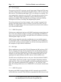
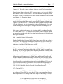
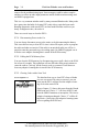
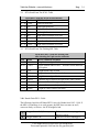
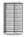
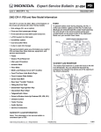
Module 3 PGMFI Flash Type Diagnostic Trouble Codes Author: Grant Swaim E-mail: [email protected] URL: www.tech2tech.net Phone: (336) 632-9882 Fax: (336) 632-9688 Postal Address: Tech-2-Tech Website PO Box 18443 Greensboro, NC 27419 Physical Address: 220-4 Swing Rd Greensboro, NC 27409 Last Update: April 2000 IMPORTANT - READ ! Do not read or study this information unless you agree to the following conditions: The information in this training module is the intellectual property of N. Grant Swaim and is copyrighted by Sure Seal Products Inc. Subscribers to the Tech-2-Tech website, and persons participating in Tech-2-Tech’s on-line training program are entitled to read this material on-line. You may also click on the “save” icon on the Acrobat viewer and save a copy to your local computer. You may save a copy of this file on one computer and it must be viewed from that one computer. You may also print one copy of this file for your viewing. If the printed copy becomes illegible, or lost, an additional copy may be printed. Tech-2-Tech offers the following training modules in printed manual, CD-ROM, and on-line formats. PGMFI Training Modules • • • • • • • • • • • • • • • • • • • • • • • The PGMFI System Overview—Part 1 The PGMFI System Overview—Part 2 PGMFI Flash Type DTCs Inputs / Outputs—Part 1 Inputs / Outputs—Part 2 Engine Control Module Air Flow / MAP Sensor—Base Inj Pulse Width Fuel Delivery System Closed Loop Strategies—Theory Closed Loop Strategies—Case Studies Thermistor Inputs Throttle Position Sensor EGR Valve Lift Sensor MAP / BARO Sensor Ignition Inputs Vehicle Speed Sensor Oxygen Sensor Lean Air Fuel Sensor Miscellaneous Input Signals Fuel Injectors—Multi-Port Injection Fuel Injectors—Dual Point Injection Ignition System—Outputs Idle Air Control Valve OBD-II Training Modules • • • • • • • • • • • • • • • On Board Diagnostics—General Overview Diagnostic Trouble Codes MIL / Freeze Frame Scan Tool Scan Tool—Advanced Monitor Tests—Overview Comprehensive Component Monitor Catalyst Monitor EGR Monitor Evaporative Monitor Fuel System Monitor Misfire Monitor Oxygen Sensor Monitor Oxygen Sensor Heater Monitor “P” Codes Miscellaneous Training Material • Glossary of Terms 2000 © - All Rights Reserved Sure Seal Products Inc - Greensboro, NC Visit Our Website: www.tech2tech.net Page 3-1 3 PGMFI Flash Type DTCs 3.1 General Overview All Honda PGMFI systems are equipped with a self-diagnosing feature. The system will light a malfunction indicator light (MIL) and store a diagnostic trouble code (DTC) in memory when a malfunction is sensed in an input signal (and output signals on OBD-II equipped Hondas). Honda actually uses two different types of DTCs, the scan tool retrievable “P” codes and the MIL flashing type. In this training series we will focus on the flashing DTCs. The Honda PGMFI system has maintained a diagnostic trouble code (DTC) reporting system from the first systems to present. This DTC reporting system is in addition to the scan tool retrievable DTCs. This reporting system was the only way to retrieve PGMFI diagnostic information until an engine control module (ECM) data link connector (DLC) was added. The first DLCs (3-pin type) were added to 92 Civics / Preludes and 1994 Accords. This was a proprietary protocol and was not OBD-II compliant. It allowed a tech to retrieve DTCs with a scan tool in addition to reading flash DTCs. A scan tool could also be used to read a freeze frame (FF), and view some live parameters from this DLC. In 1996 (1995 V-6 Accords) a 16-pin OBD-II DLC was added that was even more powerful. OBD-II equipped Hondas offer a set of industry standard OBD-II DTCs in addition to Honda’s flashed DTCs. The OBD-II DTCs can be retrieved using any OBD-II compliant scan tool. The Honda OEM scan tool will retrieve more data parameters than a generic scan tool. The OBD-II DTC reporting system is more detailed than Honda’s flash DTC system. Most input signals have only one flash DTC, yet may have as many as three OBD-II DTCs assigned to it. The expanded OBD-II DTC set will typically indicate information such as a high reading, a low reading, or an inconsistent reading from all the sensors. The newest Hondas have many different DTCs available. In addition to the PGMFI DTCs, you may find DTCs for automatic transmission controls, SRS (air bags), anti lock brakes, etc. This training module focuses on the PGMFI DTCs. The standard Honda flashed DTCs are readable without using any special tools. These DTCs are read by counting the number of flashes either at the engine control module ECM or at the dashboard MIL. The Honda self-diagnosing system has evolved over the years. The first Honda PGMFI system in 1985 used only 11 DTCs. By the 1998 model year over 45 different flashed DTCs have been used. All Rights Reserved 2000 Sure Seal Products Inc This manual printed 4/9/00 from the file pgmfiobd_002. Page 3.2 3-2 Visit Our Website: www.tech2tech.net DTC Strategies The majority of the DTCs represent a specific input signal. When the ECM senses a problem with an input it will illuminate the MIL and store a DTC in memory for later retrieval. The conditions that trigger a DTC are referred to as a strategy. The exact strategy that is required to set every DTC is not typically covered in service manuals. The design engineers establish the strategies and the ECMs are programmed accordingly. While knowing the exact strategy used by the ECM for each input is not crucial, it can help when diagnosing the systems. The earlier systems used very basic strategies, such as a high / low signal value strategy. If the input signal was above or below a specific level a DTC was set. The high / low signal strategy is the most common one used and is still used heavily in current Honda models. 3.2.1 OBD-II Exceptions With the more sophisticated and powerful OBD-II monitoring systems being used since 1996, more elaborate strategies are being used. Beginning with OBD-II, inputs are now checked for rationality, and signal behavior in addition to just being checked against a high / low value. OBD-II systems typically require that a malfunction occur on multiple consecutive trips before a DTC is stored and the MIL is illuminated. Also on OBD-II systems, the DTC will stay in memory and the car will not use the input until the car has completed 40 trips without a malfunction. 3.3 MIL Light When a malfunction is sensed, the ECM will illuminate the MIL and store a DTC. The car will ignore the input for the remainder of the trip and substitute information to the ECM from an internal table. When the car is recranked the ECM will attempt to use the input again. If the input is still malfunctioning the ECM will again ignore the input, illuminate the MIL, and use a built in default value. The MIL had several different looks over the years. It has been labeled "PGMFI", "Check Engine" and "Check" (inside a logo of an engine). Beginning in the late 1980s and early 1990s some Honda models could also set automatic transmission DTCs. The automatic transmission DTCs used the "S”, "S3" and "D4" as the MIL. This training module only covers PGMFI DTCs, not automatic transmission DTCs. 3.3.1 OBD-II Exceptions Beginning with OBD-II equipped Hondas the MIL command status (ON/OFF) can be read from a scan tool. If the ECM has commanded the MIL to be on, it will All Rights Reserved 2000 Sure Seal Products Inc This manual printed 4/9/00 from the file pgmfiobd_002. Visit Our Website: www.tech2tech.net Page 3-3 be listed in the all parameters list on your scan tool. This is a good check to make sure that the MIL light bulb or MIL circuit has not been disabled. On OBD-II equipped models some DTCs will not set and illuminate the MIL unless a malfunction occurs on multiple consecutive trips. Some DTCs require a malfunction to occur on up to 3 consecutive trips before the MIL is illuminated. The MIL is not extinguished on an OBD-II car until the car is driven on three consecutive trips without the malfunction occurring again. 3.4 Retrieving DTCs 3.4.1 Read at ECM Image 3-1 3-Pin DLC Location In the earlier systems the DTCs were read directly at the ECM. When the MIL was lit, you would turn the key to "run" and read the codes by counting the flashes from a light emitting diode (LED) on the ECM. There are two different styles of direct read LED systems. The two different styles are covered in detail in the “Reading DTCs” section. 3.4.2 Read at MIL / 2-Pin Service Check Connector (SCS) Image 3-2 Service Check Connector On later systems a 2-pin service check connector (SCS) is jumpered and the codes are flashed on the dashboard MIL. Image 3-1 shows the 2-pin SCS (marked by white arrow). This connector is typically located behind the dash at the lower right corner. Note that there is another connector right beside the 2-pin SCS, a 3-pin connecter. This is a data link connector (DLC) and is used by a scan tool to retrieve serial data from the ECM. It is easy to confuse this connector for the SCS. The DLC is a 3-pin connector, but sometimes only has two wires in the connector. Always jump the wires that are in the connecter with only 2 cavities. All Rights Reserved 2000 Sure Seal Products Inc This manual printed 4/9/00 from the file pgmfiobd_002. Page 3-4 Visit Our Website: www.tech2tech.net All the 2-pin SCSs can be jumpered by using a wire, and the later systems have a SCS tool available from Honda. The Honda SCS tool that works on all late model systems is part # 07PAZ-0010100 and retails for $3.75 (shown in Image 3-2). 3.4.3 Read at MIL / SCS Located in OBD-II Connector Image 3-3 SCS 16-Pin Jump Pins On the 1998 and up Accords the SCS was moved from a separate 2-pin connector to the 16-pin OBD-II DLC. SAE only defines a few of the 16 pins and the manufacturers, in any way they would like, can use the remaining pins. In this case Honda chose to use two of them as a SCS. To short the SCS you need to jump pins 4 and 9 as shown in Image 3-3. That will be the 4th pin from the top left corner when looking at the mating face of the DLC and the wide part of the connector is at the top and the 1st pin on the bottom left corner when looking at the mating face of the DLC and the wide part of the connector is at the top. You can always check the wire colors on the backside of the DLC; jump the brown and black wires. Image 3-4 Jumping SCS The 1998 Honda Accord service manual actually lists a special SCS jumper for this application; however, it was never produced. Honda recommends shorting the SCS connector with the Honda OEM scan tool. Manually shorting this connector works fine! Now is where it gets interesting! You can indeed jump the SCS with the OEM scan tool. You navigate to the proper place in the scan tool menu and jump the SCS by picking “Jump SCS”. The only problem is when you leave this area to do anything else with the scan tool; you loose the SCS jumpered condition. As the Honda OEM scan tool is programmed at present, you cannot jumper the SCS and use the tool for any other useful purpose at the same time. All Rights Reserved 2000 Sure Seal Products Inc This manual printed 4/9/00 from the file pgmfiobd_002. Visit Our Website: www.tech2tech.net Page 3-5 It is important to be able to jump the SCS and use the scan tool for diagnostics at the same time. As you will see in the OBD-II section, jumpering the SCS does more than just allow you to properly set the ignition timing. Jumpering the SCS also makes all DTCS set (illuminate MIL) on the first malfunction, even though their normal strategy may require as many as three malfunctions to set. This makes the diagnostic process easier and faster. Obviously with the scan tool plugged up you will not be able to jump pins 4 and 9 from the face of the 16-pin OBD-II DLC. To jump the SCS with a scan tool plugged up to the OBD-II DLC, jump the wires (brown and black) in the harness, behind the DLC. It is easy to pop the DLC out of its holder and get to the wires on the back side of the 16-pin connector. Actually the black wire is ground, so you could even simplify this by simply jumping the brown wire to chassis ground. Another easy way to do this is to just clamp both wires with one “bed of nails” type clip. This procedure is shown in Image 3-4. The table in Section 3.8 identifies the models that are directly read at the ECU. The table in Section 3.9 identifies which ones are read at the dashboard MIL after the service connector is shorted. 3.5 3.5.1 Reading DTCs OBD-I Systems When a malfunction is sensed on an input circuit, the ECM will ignore the specific input and resort back to a preset internal value. When this happens it will also light the MIL and store a DTC to indicate which input has failed. The input will be ignored until the car is restarted and the ECU will attempt to use the input again. If a malfunction is sensed it will Image 3-5 ECM/PCM LED Readouts repeat the process. The DTC that was stored in the ECM memory will be retained indefinitely as long as power to the ECU is maintained. The DTCs can be retrieved and read at a later time. Of the direct read, at the ECU, systems there are two different styles of LEDs. The earliest systems used a series of 4 LEDs in a row that were numbered 8, 4, 2 and 1. You simply add up the numbers on the lit LEDs to get the DTC. (shown on top ECM in Image 3-5) The generation after the 4 LED systems uses a single LED that blinks. You count the blinks of the single LED to determine All Rights Reserved 2000 Sure Seal Products Inc This manual printed 4/9/00 from the file pgmfiobd_002. Page 3-6 Visit Our Website: www.tech2tech.net the DTC (shown on the bottom ECM in Image 3-5). The single blinking light, whether read at the ECU or on the dash board MIL, has two different styles. On the earlier systems, all blinks stood for a "1". You simply count the number of blinks to determine the DTC. Each DTC is separated by a 3 second pause. When the DTCs became numerically large it became impractical to display only "1"s. The later systems use a long blink and a short blink. The long blinks count as "10" and the short blinks count as "1". For example, 3 long blinks and 1 short blink stands for a 31 DTC. The earlier systems only store one DTC at a time. The later systems can store multiple DTCs. The multiple DTCs are displayed sequentially with a pause between each DTC. When multiple DTCs are experienced, you need to let it go through the sequence several times to make sure you read them all and read them correctly. 3.6 Using This Information While Diagnosing The ability of the Honda PGMFI system to self diagnose itself and store DTCs for later retrieval is indeed the good news part. When there is a failure that sets a DTC the diagnosing process is usually much faster and easier. The bad news is that often problems are present without setting a DTC. The situation that happens all too often is that techs get lazy and assume there is no problem since a DTC has not been set. In the real world, many problems with noticeable symptoms can occur, and never set a DTC. The strategies used to set a DTC prior to 1996 (non-OBD-II models) were fairly conservative and used little or no logic. Most of the strategies were based on simple high / low limit strategies and the input parameter had to be almost an open or a short to set a DTC. For an example, here are two real world problems that do not usually set a DTC: 3.6.1 Defective Engine Coolant Temperature (ECT) Sensor Screen Capture 3-1 The ECT sensor on a Honda PGMFI system has been known to fail without setting a code. The strategy established to set a code on the ECT sensor input voltage appears to be a simple high / low voltage strategy. The high and low "trigger" voltage appears to be a very conservative and wide range. I have substituted the ECT sensor with a variable resistor, and ran Hondas on ranges from 250 ohms to 20,000 ohms without a DTC setting. The ECT sensor has to almost go to an open or a short to set a DTC. An ECT sensor will commonly fail by sending a All Rights Reserved 2000 Sure Seal Products Inc This manual printed 4/9/00 from the file pgmfiobd_002. Visit Our Website: www.tech2tech.net Page 3-7 cold coolant signal to the ECM after the car is warmed up, as shown in Screen Capture 3-1. This really causes problems if the car is cut off and recranked hot. The cold signal from the defective ECT sensor, at start up will cause the ECM to drive the PW as wide as 60ms or more. This rich condition will typically flood a hot Honda, causing it to not start. For a more detailed explanation of this situation read Chapter 11 – Thermistor Inputs. A simple high / low voltage limit will not catch this problem as long as the ECT sensor values stay within the acceptable range. The ECT sensor shown in Screen Capture 3-1 did not set a DTC, even with the voltage jumping between .6v and 4.25volts. Obviously, this is a situation that is physically impossible. The engine coolant cannot go from 200 degrees to 0 degrees and back to 200 degrees in a matter of seconds. With a more sophisticated strategy, this situation could be caught and have the ECM store an ECT DTC. The strategies used with the OBD-II equipped Hondas are more advanced (they also check for signal rationality) and will typically catch these types of problems. 3.6.2 Camshaft Timing Set Incorrectly The Manifold Absolute Pressure (MAP) Sensor has a major effect on the base injector (PW). The MAP sensor is monitoring engine vacuum and is effectively a load detector for the PGMFI system. When a drop in manifold vacuum is present (indicating a load) the ECM will increase the PW. If the camshaft timing is off (even by one tooth) the manifold vacuum drops and the PW is widened in anticipation of the load the ECM "thinks" the engine is experiencing. The car can be sitting in your shop idling and the ECM simply thinks that the car is climbing Pikes Peak! Again if the strategy is based on a simple high / low input voltage range test, this malfunction would go unnoticed. A slightly more sophisticated strategy could recognize that the low manifold pressure should not be present when the throttle is closed and the vehicle is sitting still. Rationality testing used on OBD-II vehicles will typically recognize this problem and set a code. When a DTC is set due to an irrational relationship between two or more inputs, the descriptor of the DTC will end in “as expected”. For example, this scenario would probably set the DTC “P1128 – Manifold Absolute Pressure Lower Than Expected”. 3.7 Clearing DTCs As soon as a stored DTC is recorded it should be cleared before any diagnostics are performed. When a DTC is stored, the ECM has a pre-programmed strategy that is implemented. The strategy could be as simple as substituting a fixed pa All Rights Reserved 2000 Sure Seal Products Inc This manual printed 4/9/00 from the file pgmfiobd_002. Page 3-8 Visit Our Website: www.tech2tech.net rameter for the malfunctioning input. Some strategies could be rather complex and have an effect on other input parameters and/or disable monitor testing used on OBD-II equipped cars. This is a very common mistake made by many seasoned Honda techs. Many techs have gotten into the habit of clearing DTCs only after a repair has been made. Running diagnostics with stored DTCs on later model Hondas could cost you dearly in diagnostic time, do not do it! There are several ways to clear the DTCs: 3.7.1 Disconnecting Power to the Car You can always disconnect power to the entire car by disconnecting the battery. This is not the best way to reset DTCs since it also will require you to re-program the radio and other accessories. If the radio is an anti-theft radio you will be required to enter the password to get it working again. On OBD-II equipped cars it will also erase adaptive learning that is stored in the ECM memory. 3.7.2 Pulling the ECM Memory Fuse You can clear the ECM memory by disconnecting power (pull a fuse) to the ECM for at least 10 seconds. This technique will not affect the radio-preset stations or cause the radio to "lock up" till the security code is re-entered. It will however loose any adaptive learning that is stored in the ECM memory. 3.7.3 Clearing Codes with a Scan Tool Screen Capture 3-2 The absolute best way to clear DTCs from a Honda is to use a scan tool. By using a scan tool, you can reset just the DTCs and not reset the adaptive learning or clear the entire ECM. Screen Capture 3-2 shows this menu from the Honda OEM scan tool. Choice “1” will clear all DTCs and reset the OBD-II monitors to incomplete. This leaves adaptive learning unchanged. Choice “2” will do all that choice 1 does plus clear adaptive learning (same effect as pulling the ECM fuse). All Rights Reserved 2000 Sure Seal Products Inc This manual printed 4/9/00 from the file pgmfiobd_002. Visit Our Website: www.tech2tech.net 3.8 Page 3-9 DTCs Read From The ECM - Table Read DTCs from the ECMs of these models Year Model ECM Location 85 - 89 Accord Under left front seat 86 - 87 Civic Under right front seat 88 - 91 Civic Right front floorboard at firewall 85 - 87 CRX Under right front seat 88 - 91 CRX Right front floorboard at firewall 85 - 87 Prelude - All Left of rear seat, under an interior panel 88 - 89 Prelude - All Right front floorboard at firewall 90 - 91 Prelude - 2.0 Right front floorboard at firewall 3.9 Year 90-97 98-99 86-98 97-98 93-97 95-98 90-91 92-96 97-98 DTCs Read From The Flashing MIL Table Read these DTCs from the flashing MIL after shorting the 2-pin service connector Model Service Connector Location Accord At right bottom edge of dash Accord Integral with the OBD-II DLC – short the brown and black wire together Civic At right bottom edge of dash CRV At right of center console, near dash Del Sol At right bottom edge of dash Odyssey At bottom edge of dash to the right of the center console Prelude-2.1 right rear corner of the engine compartment Prelude At front of center console (under dash) Prelude At right of center console, near dash 3.10 Honda Flash DTCs -Table The following chart lists all flashed DTCs in use by Honda from 1985 - 1998. If the MIL is lit and there is no code present, the MIL does not come on at all, comes on dimly, or flickers - the ECM might be bad. 1 Oxygen Sensor "A" (Primary) 2 Oxygen Sensor "B" Defective circuit or unplugged / defective sensor Defective circuit or unplugged / All Rights Reserved 2000 Sure Seal Products Inc This manual printed 4/9/00 from the file pgmfiobd_002. Page 3-10 Visit Our Website: www.tech2tech.net 7 MAP Sensor (Manifold Absolute Pressure) CKP Sensor (Crankshaft Position Sensor) MAP Sensor (Manifold Absolute Pressure) ECT Sensor (Engine Coolant Temperature) TP Sensor (Throttle Position) 8 TDC Sensor (Top Dead Center) 9 CYP Sensor (Cylinder) 3 4 5 6 14 IAT Sensor (Intake Air Temperature) EGR Lift Sensor (Exhaust Gas Recirculation) BARO Sensor (Atmospheric Pressure) IAC Valve (Idle Air Control) 15 Ignition Output Signal 16 Fuel Injector System 17 VSS (Vehicle Speed Sensor) 19 20 Automatic Transmission Lock Up Control Solenoid Valve Electrical Load Detector 21 VTEC Solenoid Valve 22 VTEC Oil Pressure Switch 23 KS (Knock Sensor) 31 Automatic Transmission Signal "B" Primary Oxygen Sensor – Heater Fuel Supply System 10 12 13 41 43 defective sensor Defective circuit or unplugged / defective sensor Defective circuit or unplugged / defective sensor Mechanical problem / disconnected piping Defective circuit or unplugged / defective sensor Defective circuit or unplugged / defective sensor Defective circuit or unplugged / defective sensor Defective circuit or unplugged / defective sensor Defective circuit or unplugged / defective sensor Defective circuit or unplugged / defective sensor Defective circuit or unplugged / defective sensor Defective circuit or unplugged / defective sensor Missing or defective ignition output signal Defective circuit or unplugged / defective fuel injector Defective circuit or unplugged / defective sensor Defective circuit or unplugged / defective solenoid valve Defective circuit or unplugged / defective sensor Defective circuit or unplugged / defective solenoid valve Defective circuit or unplugged / defective oil pressure switch Defective circuit or unplugged / defective sensor Defective circuit or unplugged / defective sensor Circuit malfunction Defective or malfunctioning fuel supply system All Rights Reserved 2000 Sure Seal Products Inc This manual printed 4/9/00 from the file pgmfiobd_002. Page 3-11 Visit Our Website: www.tech2tech.net 45 System Too Lean or Too Rich 48 LAF Sensor (Lean Air Fuel) 54 CKF Sensor (Crankshaft Speed Fluctuation) TDC Sensor 2 (Top Dead Center) 58 61 63 65 67 70 71 72 73 74 75 76 80 86 90 91 92 Oxygen Sensor, Heated - Sensor 1 (Primary) Oxygen Sensor, Heated - Sensor 2 (Secondary Oxygen Sensor Heater (Secondary) Catalyst system Efficiency Below Threshold Automatic Transmission Cylinder 1 Misfire or a Random Misfire Cylinder 2 Misfire or a Random Misfire Cylinder 3 Misfire or a Random Misfire Cylinder 4 Misfire or a Random Misfire Cylinder 5 Misfire or a Random Misfire Cylinder 6 Misfire or a Random Misfire Exhaust Gas Recirculation ECT Sensor (Engine Coolant Temperature) Evaporative Emission Control System Fuel Tank Pressure Sensor Evaporative Emission Control System Malfunction in the fuel monitoring systems Defective circuit or unplugged / defective sensor Defective circuit or unplugged / defective sensor Defective circuit or unplugged / defective sensor High voltage, low voltage, or slow response High voltage, low voltage, or slow response Malfunctioning or defective oxygen sensor heater Malfunctioning or defective catalyst system Malfunction with the automatic transmission controls A condition is present that is creating a cylinder misfire A condition is present that is creating a cylinder misfire A condition is present that is creating a cylinder misfire A condition is present that is creating a cylinder misfire A condition is present that is creating a cylinder misfire A condition is present that is creating a cylinder misfire Insufficient flow detected Circuit range / performance problem Leak detected in the fuel tank area Low input Insufficient purge flow All Rights Reserved 2000 Sure Seal Products Inc This manual printed 4/9/00 from the file pgmfiobd_002.