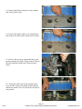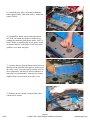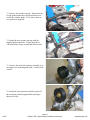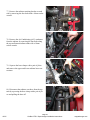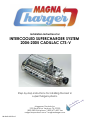
1
Installation Instructions for:
INTERCOOLED SUPERCHARGER SYSTEM
2004-2005 CADILLAC CTS-V
Step-by-step instructions for installing the best in
supercharger systems.
Magnuson Products Inc
1990 Knoll Drive, Ventura, CA. 93003
(805) 289-0044 phone * (805) 677-4897 fax
magnusonproducts.com * magnacharger.com
89-89-60-015 Rev C
.
or only
d
r
e
l
ate
til
dis ed w
e
Us ioniz
de-
INSTALLATION MANUAL
Magna Charger
GM 5.7 Liter Engine,
2004-2005 Cadillac CTS-V
Please take a few moments to review this manual thoroughly before you begin work:
Μake quick parts check to make certain your kit is complete (see shipper parts list in this
package). If you discover shipping damage or shortage, please call our office immediately.
Take a look at exactly what you are going to need in terms of tools, time, and experience.
Review our limited warranty with care.
When unpacking the supercharger kit DO NOT lift the supercharger assembly by the black
plastic bypass actuator. This is pre-set from the factory and can be altered if used as a lifting
point!
Caution: Relieve the fuel system pressure before servicing fuel system components in order
to reduce the risk of fire and personal injury. After relieving the system pressure, a small
amount of fuel may be released when servicing the fuel lines or connections. In order to
reduce the risk of personal injury, cover the regulator and fuel line fittings with a shop towel
before disconnecting. This will catch any fuel that may leak out. Place the towel in an
approved container when the job is complete.
Use only premium fuel, 91 octane or better.
Magna Charger systems are manufactured to produce about 20 RWHP
per pound of boost at sea level. High altitudes will produce different numbers.
Our Magna Charger kits are designed for engines in good mechanical condition only.
Installation on high mileage or damaged engines is not recommended and may result in engine failure, for
which we are not responsible. Magna Charger is not responsible for the engine or consequential
damages.
Aftermarket engine recalibration devices that modify fuel and spark curve (including, but not
limited to programmers) are not recommended and may cause engine damage or failure. Use of
non-Magna Charger approved programming will void all warranties. If you have any questions,
call us.
After you finish your installation and road test your vehicle, please fill out and mail in the limited
warranty card, so we can add you to our files (this is important for your protection).
A new GM fuel filter is recommended at the time of supercharger installation.
Stock spark plugs and stock plug gap is recommended
Drive belt= Gates# K061010
Air Filter= K&N# 33-2289
Tools Required:
Metric wrench set
¼” - 3/8” and ½” drive metric socket set (Standard & Deep)
3/8”and ½” drive Foot pound and inch pound torque wrenches
Phillips and flat head screwdrivers
Fuel line quick disconnect tools (included in kit)
Small or angled 3/8 drill motor
Drain pan
Hose cutters
Hose clamp pliers
Safety glasses
Metric Allen socket set 3/8 drive
Shop vacuum cleaner
10/05
Contact information:
Magnuson Products Inc
Magna Charger Division
1990 Knoll Drive
Ventura, CA 93003
Sales/Tech support 805-289-0044
Websites:
www.magnusonproducts.com
www.magnacharger.com
Email:
[email protected]
Page 2
Cadillac CTS-V Supercharger Installation Instructions
magnacharger.com
1. Start the supercharger installation by removing
the lower rear seat cushion by pushing in at the base
and then pulling up. Remove the cushion to gain
access to the two rear fuse centers located where the
carpet meet the seat base.
2. Once the seat cushion has been removed pull
back the carpet where it meets the seat base on the
left (driver) side to expose the fuse center. Remove
the fuse center cover and examine the legend printed
inside the cover to locate the fuse marked “Audio”.
Remove the 10 amp “Audio” fuse so the vehicles
PCM (engine management computer) can be
re-programed safely. THIS FUSE MUST BE
REMOVED BEFORE REPROGRAMING!
Audio fuse
3. Pull back the carpet where it meets the seat base
on the right (passenger) side to expose the other fuse
CENTER. Remove the fuse center cover and examine the legend printed inside the cover to locate the
fuse marked “Fuel Pump Mtr”.
Fuel Pump Mtr
fuse
4. Remove the stock “Fuel Pump Mtr” fuse and
replace it with the 30 amp fuse supplied. Replace
the fuse center cover.
New 30amp fuse
10/05
Page 3
Cadillac CTS-V Supercharger Installation Instructions
magnacharger.com
5. Locate the OBD II plug connection along the bottom edge of the dash to the right of the hood release
lever.
OBD II plug
connection
6. Connect the cable supplied with the microtuner to
the 9-pin connector at the top of the handheld unit.
Use the thumbscrews to secure the cable to connector. Connect the other end to your OBD II plug connection. Make sure this connection is seated all the
way in and that it is secure. This connection must
remain secure during programming. NOTE: It is
very important that the instructions for the programmer are carefully read and understood. All steps
should be followed exactly. If you have any questions, contact Superchips or Magnuson Products Inc
immediately.
7. Turn the ignition key to the on or run position
but do not start the vehicle. To begin programming your vehicle, you must press the YES button.
Press the YES button once to start the programming
cycle. The programming process takes about five
minutes. The handheld unit will inform you that the
programming process has completed and to turn the
ignition off and disconnect the cable. Only at this
time should the ignition be turned off and the cable
removed.
8. *DO NOT DISTURB THE CABLE OR TURN
THE IGNITION OFF DURING THIS TIME! IF
THE PROGRAMMING IS DISRUPTED YOUR
COMPUTER WILL NOT START OR RUN YOUR
VEHICLE! If you should get the message “ERROR
NO VIN STORED OR THIS MODEL YEAR NOT
SUPPORTED” on the Microtunner display, remove
the cable and Microtunner from the OBD II port and
take your vehicle back to your Cadillac dealer and
ask to have your PCM program updated to the current program.
10/05
Page 4
Cadillac CTS-V Supercharger Installation Instructions
magnacharger.com
9. Replace the “Audio” fuse and the fuse center
cover. Replace the lower rear seat cushion by pushing in at the base and then pushing down. Take care
to ensure the seatbelt buckles are placed in the slots
provied for them in the back edge of the seat cushion.
10. Remove the Negative battery connector from
the battery. Snap the black plastic terminal off the
connector and then remove the battery connector
with a 8mm wrench. Position the connector away
from the battery so that it won’t make accidental
contact during the supercharger installation.
11. Squeeze and pull to remove the two caps that
cover the wiper arm attachment nuts.
12. Remove the wiper arm attachment nuts with a
15mm socket wrench.
10/05
Page 5
Cadillac CTS-V Supercharger Installation Instructions
magnacharger.com
13. Note: The position of the wiper arms on the
windshield and then pull up firmly to remove the
wiper arms.
14. Remove the rubber weather strip from the front
edge of the wiper arm apron.
15. Remove the four 7mm bolts that secure the
wiper apron on the right (passenger) side.
16. In the corner of the left (driver) side wiper
apron, remove the bolt that secures it with a 10mm
socket wrench.
10/05
Page 6
Cadillac CTS-V Supercharger Installation Instructions
magnacharger.com
17. Pull the right wiper apron forward at the center,
then remove the left apron completely.
18. Located on the bottom of the wiper assembly is
the wiper motor electrical connector. Disconnect the
connector from the motor.
19. Remove the wiper assembly retaining bolt near
the center of the windsheild with a 13mm socket
wrench.
20. Remove the wiper assembly complete from the
vehicle.
10/05
Page 7
Cadillac CTS-V Supercharger Installation Instructions
magnacharger.com
21. From the top surface of the left wiper arm lever,
measure down 3/8”(10mm) and scribe a line across
the lever. Using a suitable grinder or saw remove all
the material above this line.
Remove
3/8”
22. Install the thick spacer washer supplied over the
wiper assembly mounting hole.
23. Re-install the wiper assembly into place. Note:
The mounting bolt will pass through the spacer
washer installed in the previous step.
24. Tighten the mounting bolt securely and re-attach
the electrical connector on the bottom of the wiper
motor.
Spacer washer
10/05
Page 8
Cadillac CTS-V Supercharger Installation Instructions
magnacharger.com
25. Replace the wiper aprons, mounting screws and
weather strip into their original locations.
26. Replace the wiper arms into their original positions on the spindle shafts and torque the attachment
nuts to 26 ft-lbs.
27. On the top of the strut towers remove the two
bolts on each side that secure the strut tower brace
with a 18mm socket wrench.
28. Remove the strut tower brace completely, as it
cannot be reused with the supercharger. A new strut
tower brace is included with this system and will be
installed in a later step. Replace the bolts into their
original holes temporarily tighten them.
10/05
Page 9
Cadillac CTS-V Supercharger Installation Instructions
magnacharger.com
29. Pull up firmly at the front and back of the engine
cover to remove it. It will not be reused.
30. Remove the radiator mask by removing the two
push rivets out along the front edge. Pull up firmly
along the back edge to unclip the mask for removal.
Center
31. To remove the push rivets, use a small straight
blade screwdriver to pry up the center of the rivet
and then the outer body.
Body
Remove push rivets
at these locations
32. Raise the front of the vehicle on jackstands or a
lift and remove the lower front splash panel from the
bottom of the vehicle. Remove the panel by removing the 13 push rivets in the areas shown.
10/05
Page 10
Cadillac CTS-V Supercharger Installation Instructions
magnacharger.com
33. Remove the eight push rivets that secure the top
edge of the front fascia as shown.
34. Along the front edge of both front wheel wells
remove the push rivets as shown.
Lock bolts
35. Rotate the steering wheel to full lock so you
can push the wheel well splash panel out of the way
to gain acecess to the two fascia lock bolts on each
side. As you loosen the the nuts on the lock bolts the
fascia panel will drop down forming a gap between
the fascia and the fender. It is not necessay to remove the lock bolt nuts or the lock bolts themselves.
36. The lock bolts are located before and after
the marker lamp, where the fascia panel meets the
fender as shown in this photo from the inside of the
fascia.
10/05
Marker light
Page 11
Cadillac CTS-V Supercharger Installation Instructions
magnacharger.com
37. After loosening the lock bolts, pull forward on
the fascia panel. The lock bolts will slide forward in
their “keyhole” shaped holes and allow the fascia to
detach from the vehicle.
Pull forward
38. On both sides of the fascia disconnect the
marker light electrical connection.
39. On both sides of the fascia disconnect the turn
signal/driving light electrical connection. Remove
the fascia carefully from the vehicle and set it aside.
40. Remove the air tube by loosening the clamps
with a 8mm nut driver at the throttle body and Mass
Air Flow meter (MAF).
10/05
Page 12
Cadillac CTS-V Supercharger Installation Instructions
magnacharger.com
41. Remove the air tube completely, as it will not be
reused.
42. On the left (drivers) side of the throttle body,
disconnect the Electronic Throttle Control (ETC)
connector.
43. Disconnect the Throttle Position Sensor (TPS)
connector on the right (passenger) side of the throttle
body.
44. Disconnect the eight injector electrical connectors.
10/05
Page 13
Cadillac CTS-V Supercharger Installation Instructions
magnacharger.com
45. Disconnect the two ignition coil pack connectors.
46. Unclip the Engine Knock Sensor (Knock)
connector from its location on the back of the intake
manifold. Next, disconnect the Knock connector
from the wiring harness connector.
47. Disconnect the Manifold Absolute Pressure
(MAP) sensor connector at the rear of the intake
manifold.
48. Disconnect the Positive Crankcase Ventilation
(PVC) hose from the right side of the throttle body.
10/05
Page 14
Cadillac CTS-V Supercharger Installation Instructions
magnacharger.com
49. Disconnect the engine valley cover vent hose
from the nipple in the intake manifold.
50. Disconnect the vacuum brake booster valve
from its mounting grommet on the booster.
51. Above the drivers (right) side valve cover,
disconnect the Evaporative Purge Solenoid (EVAP)
electrical connector.
52. Press the white release trigger on the
Evaporative emission (Evap) pipe connector to
remove it from the barb on the intake manifold.
Disconnect the other end of the Evap pipe from the
purge solenoid.
10/05
Page 15
Cadillac CTS-V Supercharger Installation Instructions
magnacharger.com
53. Disconnect the Evap pipe from the rear of the
purge solenoid. Follow the Evap pipe to the right
rear of the engine and unclip it from the fuel rail.
Disconnect the Evap pipe from the smaller quickrelease fitting using the supplied removal tool. Snap
the tool on the pipe and push it into the quick release
fitting to release the pipe.
Removal tool
54. Remove the Purge solenoid and EVAP line by
pulling the solenoid free from its mounting location
on the left side of the intake manifold.
55. On the left side of the intake manifold, locate
the fuel pressure test port at the front of the fuel
rail and remove the cap. CAUTION! The fuel in
the system is under pressure! Relieve the pressure
in the system by depressing the check valve with
a screwdriver and collecting the fuel with a shop
towel.
56. Remove the retaining clip from the fuel line
quick-release connection.
10/05
Page 16
Cadillac CTS-V Supercharger Installation Instructions
magnacharger.com
57. Disconnect the fuel pipe from the large quickrelease fitting using the supplied removal tool. Snap
the tool on the pipe and push it into the quick release
fitting to release the pipe.
58. Remove the two coolant lines attached to the
bottom of the throttle body.
Coolant lines
59. Remove the three bolts attaching the throttle
body to the intake manifold with a 10mm socket
wrench. Set the throttle body and bolts aside for
later installation on the supercharger assembly.
60. Remove the three bolts attaching the throttle
body to the intake manifold with a 10mm socket
wrench. Set the throttle body and bolts aside for
later installation on the supercharger.
10/05
Page 17
Cadillac CTS-V Supercharger Installation Instructions
magnacharger.com
61. Remove the ten intake manifold bolts with a
8mm socket wrench. Note: You may not be able
to completely withdrawal all ten bolts from the
manifold after unthreading them.
62. Using a shop vacuum cleaner, remove any dirt
or debris from the intake port and engine valley
cover area.
63. Cover the intake ports with tape or clean rags.
64. On the engine valley cover, remove the two
black rubber Knock Sensor covers by gently prying
them up using a small straight blade screwdriver.
Disconnect the electrical connectors by squeezing
the sides of the connectors with a pair of long jaw or
needle nose pliers and pulling them up.
10/05
Page 18
Cadillac CTS-V Supercharger Installation Instructions
magnacharger.com
65. Remove the Knock sensors by using a ratchet
and a deep 22mm socket.
66. Remove the engine valley cover and gasket by
removing the ten bolts with a 10mm socket wrench.
67. Remove the accessory serpentine belt by rotating the tensioner bolt with a 15mm wrench. Release
the slack and then pull the belt off the tensioner
pulley.
68. The gasket will be reused, the original valley
cover will not. Inspect the gasket for any damage
and then re-install. Note: It will only fit correctly in
one position.
Gasket
10/05
Page 19
Cadillac CTS-V Supercharger Installation Instructions
magnacharger.com
69. Install the new valley cover and ten flathead
bolts supplied with a 5mm Allen socket. Torque the
bolts to 18ft-lb.
70. Reinstall the knock sensors and torque them
to15 ft-lb. Re-attach the electrical connectors by
pushing the connector down firmly until a “click” is
heard. Before re-installing the covers, apply a bead
of silicone adhesive to the sides of each cover then
push the covers back into place.
71. Remove the tape from the knock sensor wires so
that they can be installed in the grooves in the top of
the valley cover. Use some tape to hold the wires in
place temporarily, and then use silicone adhesive to
retain the wires permanently. Insert the six O-rings
supplied in the recesses in the new valley cover.
72. Remove the two coolant vent pipe bolts with a
10mm socket wrench.
10/05
Page 20
Cadillac CTS-V Supercharger Installation Instructions
magnacharger.com
73. Remove the coolant vent pipe. Ensure that the
O-ring gaskets under the vent pipe blocks do not
stick to the cylinder heads. If so, remove them as
new gaskets are supplied.
74. Install the new coolant vent pipe with the
supplied gaskets and bolts. Torque the bolts to
106 in-lbs with a torque wrench and 10mm socket.
75. Remove the stock belt tensioner assembly by removing the two mounting bolts with a 15mm socket
wrench.
76. Install the new tensioner assembly in place of
the stock unit with the supplied bolts and torque
them to 40 ft-lbs.
10/05
Page 21
Cadillac CTS-V Supercharger Installation Instructions
magnacharger.com
77. Remove the radiator retaining bracket on each
side by removing the four bolts with a 10mm socket
wrench.
78. Remove the Air Conditioning (A/C) condensor
from the radiator by removing the four bolts along
the top and bottom radiator tanks with a 10mm
socket wrench.
79. Squeeze the hose clamps with a pair of pliers
and remove the upper and lower radiator hose connections.
80. Disconnect the radiator vent hose from the top
tank by squeezing the hose clamp with a pair of pliers and pulling the hose off.
10/05
Page 22
Cadillac CTS-V Supercharger Installation Instructions
magnacharger.com
81. On the left side of the engine, remove the A/C
pipe support tab from the fan shroud with a right
angle cross-head screwdriver.
82. Disconnect the radiator fan electrical connections on each fan by squeezing the connectors and
pulling them free.
83. Remove the radiator, fan and hoses complete by
pulling it straight up and out carefully.
84. Due to the extra power generated by the
supercharger system it is necessary to give the
harmonic balancer additional support in its location
on the end of the crankshaft. This is achieved by
“pinning” the balancer to the crankshaft with two
hardened steel dowel pins. These are the supplied
parts and tools necessary to do this.
10/05
Page 23
Cadillac CTS-V Supercharger Installation Instructions
magnacharger.com
85. Remove the stock balancer bolt from the end
of the crankshaft with an impact gun and a 24mm
socket.
86. Install the drill guide and bolt into the stock
location. Note: The smaller diameter end of the
guide goes towards the balancer.
87. Torque the guide bolt to 60 ft-lbs with a torque
wrench and 24mm socket.
88. Using a drill and the supplied drill bit, drill
Two holes in the balancer by placing the drill bit in
the two holes in the guide. Take your time, as the
material will cut slowly. Note: The drill bit has a
“shoulder” on it. Continue drilling until the shoulder
of the drill bit contacts the drill guide.
10/05
Page 24
Cadillac CTS-V Supercharger Installation Instructions
magnacharger.com
89. A light lubricant will help the drilling and
reaming process. Drill the holes in several steps
lubricating the hole and bit between each step.
90. After drilling the two holes, use the supplied
reamer to correctly size the holes. Rotate the reamer
clockwise only. Turning it the other direction will
ruin it.
91. Use some compressed air to remove any
material from the holes.
92. Remove the drill guide and bolt from the end of
the crankshaft.
10/05
Page 25
Cadillac CTS-V Supercharger Installation Instructions
magnacharger.com
93. Inspect the two new holes carefully and use
more compressed air to remove any residual
material. Install a dowel pin into each hole.
94. Use a small hammer and a drift to tap the dowel
pins in as far as they will go into the balancer.
95. Install the new balancer bolt supplied.
96. Use a torque wrench and 24mm socket to
tighten the new balancer bolt to 37 ft-lbs and then
rotate it an additional 140 degrees using a torque
angle meter. The radiator and hoses will be replaced
in a later step.
10/05
Page 26
Cadillac CTS-V Supercharger Installation Instructions
magnacharger.com
97. Locate the MAF connector and remove the tape
from the wires. Approximately 3” back from the
connector, cut the two Brown Inlet Air Tempeture
wires.
98. Using the new IAT harness, lengths of white
wire and crimps connectors supplied, install the IAT
connector and extention wires to the two ends of the
brown wires leading to the computer. It does not
matter which white wire connects to either brown
wire. The two wires from the MAF connector will
no longer be used.
To MAF
not used
New IAT harness
New wires
Crimp connectors
To computer
99. Strip about 1/4” of insulation from the ends of
all the wires, then crimp the connectors on. Using a
heat gun or blow dryer set on “High” shrink the insulation on the crimp connectors so that it contracts
around the wires completely. You must shrink the
insulation, as crimping the connections alone is
not enough to secure them!
100. Cover the new IAT harness with the split loom
supplied.
10/05
Page 27
Cadillac CTS-V Supercharger Installation Instructions
magnacharger.com
101. Locate the purge solinoid connector
and remove the plastic tape. Cut the wires
approximately 4” back from the connector.
102. Using the new lengths of color coded wire and
crimps connectors supplied to extend the purge solenoid connector wires. Strip about 1/4” of insulation
from the ends of all the wires, then crimp the connectors on. Using a heat gun or blow dryer set on
“High” shrink the insulation on the crimp connectors
so that it contracts around the wires completely. You
must shrink the insulation, as crimping the connections alone is not enough to secure them!
Crimp connectors
New wires
Wiring harness
connections
103. Cover the extended wires with the split loom
supplied.
104. Place a straight edge across the top surfaces of
the throttle body as shown.
10/05
Page 28
Cadillac CTS-V Supercharger Installation Instructions
magnacharger.com
105. Scribe a line across the upper tab on the
throttle body.
106. Using a small saw or grinder carefully remove
the material above the line until the throttle body
looks like this.
107. Install the throttle body with the new supplied
gasket onto the supercharger inlet manifold using the
original three bolts and a 10mm socket wrench.
108. Torque the three throttle body bolts to 89 inlbs.
10/05
Page 29
Cadillac CTS-V Supercharger Installation Instructions
magnacharger.com
109. Assemble the Evap solenoid bracket and bolts
onto the fuel manifold.
110. Using some of the lubricant supplied, install
the O-ring into the recess in the fuel rail. Install the
fuel manifold and bracket on the fuel rail, take care
not to pinch the O-ring.
111. Torque the fuel manifold bolts to 106 in-lbs
with a torque wrench and 10mm socket.
112. Remove the Manifold Absolute Pressure
(MAP) sensor from the stock intake manifold by tilting the sensor forward and lifting it free. Ensure that
the orange rubber seal is not missing or damaged as
it and the sensor will be re-used.
10/05
Page 30
Cadillac CTS-V Supercharger Installation Instructions
magnacharger.com
113. Apply a small amout of the grease supplied to
the MAP sensor seal and install the sensor in its new
location at the right rear of the supercharger manifold.
114. Install the MAP sensor in its new location using the supplied bracket and the button head Allen
screw with a 4mm Allen wrench.
115. Install the new intake manifold gaskets supplied onto the recesses in the manifold face. Ensure
that the gaskets are fully seated in the manifold face.
116. Remove the tape from the port surfaces and
using silicone spray or soapy water apply a light film
to allow the port gaskets to slide on the surfaces.
Do not use any petroluem based lubricants as these
will damage the port gaskets.
10/05
Page 31
Cadillac CTS-V Supercharger Installation Instructions
magnacharger.com
117. With the help of a assistant carefully set the supercharger system in place. Take care not to damage
the port gaskets.
118. Remove the split-looms that support some
of the manifold to cylinder head bolts. Start all
ten bolts by hand to ensure proper alignment of the
manifold.
119. Using a torque wrench and 10mm socket
torque the ten manifold to cylinder head bolts gradually and evenly to 89 in-lbs.
120. At the rear of the supercharger on the passenger side, plug in the MAP and new IAT connections.
IAT connector
MAP connector
10/05
Page 32
Cadillac CTS-V Supercharger Installation Instructions
magnacharger.com
121. At the firewall connect the Knock sensor connector.
122. Install the ignition coil pack connectors on
both sides of the engine.
123. Install the connecors on all eight fuel injectors.
124. Install the TPS extention harness onto the harness connector.
10/05
Page 33
Cadillac CTS-V Supercharger Installation Instructions
magnacharger.com
125. Install the TPS extention connector onto the
throttle body connection.
126. Install the ETC connector onto the throttle
body.
Purge solenoid
127. Install the purge solenoid onto the new bracket
and then install the EVAP electrical connector.
128. Use a adjustable wrench to rotate the PVC barb
on the throttle body to the approximate “Four Oclock”position as shown.
10/05
Page 34
Cadillac CTS-V Supercharger Installation Instructions
magnacharger.com
129. Install one end of a 16” length of the supplied
3/8” PCV hose onto the throttle body PCV barb.
Install the remaining end of the hose on to the passenger (right) side valve cover PCV barb.
130. At the rear of the driver (left) side valve cover,
remove the rubber cap covering the PCV barb.
Elbow fitting
131. Assemble the new PCV outlet hose by cutting a 43” length and a 2” length of the 3/8” hose.
Attach one end of each hose to the 90 degree elbow
fitting.
To inlet manifold barb
To PCV
barb
132. Install the new PCV outlet hose onto barb.
10/05
Page 35
Cadillac CTS-V Supercharger Installation Instructions
magnacharger.com
Large inlet manifold barb
133. Install the plain end of the 43”PCV outlet hose
on the passenger (right) side of the engine.
134. Insert the new check valve into the 11/32”
brake hose supplied.
135. Install the new check valve and hose onto the
brake vacuum booster.
136. On the driver (left) side of the engine connect the brake hose to the large barb on the inlet
manifold. Route the brake hose along the side of
the engine and behind the supercharger to the brake
booster.
10/05
Large inlet manifold barb
Page 36
Cadillac CTS-V Supercharger Installation Instructions
magnacharger.com
137. Locate the EVAP pipe removed earlier.
138. Using a sharp knife, carefully cut the plastic
pipe so that the end fittings can be reused.
139. Here is the fittings removed from the pipe and
the new supplied hose and clamps.
140. Secure the clamps by using a pair of side cutting pliers to crimp the loop of the clamp around the
hose. Take care not to cut the loop but only tighten
it.
10/05
Page 37
Cadillac CTS-V Supercharger Installation Instructions
magnacharger.com
141. Here is the new EVAP hose assembled and
ready for installation.
Firewall EVAP connection
Purge solenoid
142. Install the new EVAP hose onto the rear barb
of the purge solenoid and into the firewall connector.
Next, connect one end of a 12” length of 3/8” hose
to the front barb of the purge solenoid.
12” length of EVAP hose
143. Install the fuel line extention into the firewall
fuel line connector.
144. Connect the remaining end of the fuel line
extention to the fuel manifold connector
10/05
Page 38
Cadillac CTS-V Supercharger Installation Instructions
magnacharger.com
145. Re-install the fuel line retaining clip.
146. Connect the remaining end of the EVAP hose
from the purge solenoid to the small barb on the
right side of the supercharger inlet manifold.
EVAP hose
147. Install one end of a 24” length of the 1/4”
coolant line onto the right side throttle body coolant
barb. Secure the coolant line with a # 4 clamp supplied.
New hose connector
148. Route the 24” coolant line along the front of
the supercharger manifold and under the Mass Air
Flow meter (MAF). Use the supplied 1/4” hose connector and another #4 clamp to connect the coolant line to the vehicles coolant vent line using the
original clamp.
New coolant line
and clamp
10/05
Page 39
Cadillac CTS-V Supercharger Installation Instructions
coolant vent line and
clamp
Vehicle coolant vent line
magnacharger.com
coolant vent pipe barb
149. Install one end of the 20” length of 1/4” heater
hose on the coolant vent pipe barb. Secure the hose with
a #4 clamp supplied.
150. Connect the remaining end of the 20” coolant hose
to the left side throttle body barb using a #4 clamp supplied.
S/C
151. Here is the new accessory drive belt routing diagram.
ID
P/S
TEN
W/P
ALT
ID
CRANK
152. Using a long 15mm wrench to compress the tensioner, install the new belt using the diagram above.
10/05
Page 40
Cadillac CTS-V Supercharger Installation Instructions
magnacharger.com
153. Re-install the radiator into the vehicle. Reinstall the radiator hoses, fan electrical connections
and A/C line support tab. The radiator mask will be
installed in a later step.
Air Bleed
Passenger
Side
154. This is a diagram of the complete intercooler
system plumbing. Note: The routing of the hoses and
their connections.
Intercooler
Drivers Side
Heat Exchanger
Coolant Tank
Water Pump
155. At the lower A/C condensor attachment points,
remove the two bolts on each side with a 8mm
socket wrench. At these two locations the new heat
exchanger will mount.
Remove
156. Carefully slide the new heat exchanger in position, up from the bottom, in front of the A/C condensor.
10/05
Page 41
Cadillac CTS-V Supercharger Installation Instructions
magnacharger.com
157. Bolt the heat exchanger into place using
the supplied Allen bolts and a 4mm Allen socket
wrench.
158. Remove the the lower right A/C condensor
mounting bolt with a 10mm socket wrench. Install
the two reservoir brackets using the A/C mounting
bolt and a new supplied bolt in the center attachment
point on the radiator tank.
Center attachment point
Reservoir brackets
A/C condensor mount
159. Here is the intercooler reservoir tank. Note:
The slotted rail on the front surface. Ther are two
rails on the back as well.
Slotted rail
160. Here is the intercooler pump and mounting
hardware. Note: The round head bolts for mounting
the pump.
Round head holts
10/05
Page 42
Cadillac CTS-V Supercharger Installation Instructions
magnacharger.com
161. Install two of the round head bolts into the
slotted rail on the front of the reservoir as shown.
Note: That the square portion of the bolt shaft must
be aligned with the sides of the channel.
162. Mount the intercooler pump to the reservoir in
this position using the supplied Adel clamps, bolts
and nuts. Tighten the nuts securely with a 10mm
wrench.
163. Install the two remaining round head bolts into
the rails on the back of the reservoir.
164. Install the reservoir and pump assembly onto
the two brackets installed in step 158.
10/05
Page 43
Cadillac CTS-V Supercharger Installation Instructions
magnacharger.com
165. Secure the reservoir and pump assembly to
the bracket uisng the supplied nuts. Tighten the nuts
securely with a 12mm wrench.
166. Next to the left headlamp locate the air filter
box boot. The boot will need to be removed to provide more air to the air filterbox and to allow passage of the heat exchanger lines.
167. To remove the boot, drill out the two mounting
rivets at the front of the boot.
168. There are two additional retaining buttons
securing the boot. Remove these buttons and the
boot by prying them free with a large straight blade
screwdriver.
10/05
Page 44
Cadillac CTS-V Supercharger Installation Instructions
magnacharger.com
169. Cut the “J” shaped hose as shown so it forms a
“U” and a right angle “L” hose.
170. Cut approximately 3” off the short leg of the
large “L” hose supplied as shown.
171. Install one end of the 24” length of 3/4” hose
to the left side intercooler manifold barb. Secure the
hose with a #10 clamp supplied using a 8mm nutdriver.
172. Secure the remaining end of the 24” hose to
the reservoir inlet barb with a #10 clamp.
10/05
Page 45
Cadillac CTS-V Supercharger Installation Instructions
magnacharger.com
173. Attach the “U” shapped hose to the pump inlet
barb and the reservoir outlet barb using the #10
clamps supplied. Tighten the clamps securely with a
8mm nut driver.
174. Attach the “L” shapped hose to the pump outlet
barb and the heat exchanger inlet barb using two #10
clamps supplied.
175. Route the large “L” hose through the area created by removing the air box boot. Attach the short
leg of the large “L” hose to the outlet barb of the
heat exchanger with a #10 clamp.
176. Connect the remaing leg of the large”L” hose
to the left barb on the intercooler manifold and
secure it with a #10 clamp. Tighten all hose clamps
securely with a 8mm nutdriver except for the clamp
on the right side intercooler manifold barb.
10/05
Page 46
Cadillac CTS-V Supercharger Installation Instructions
magnacharger.com
Rib
177. Here is the air tube assembly components.
Note: The two different lengths of hose and the
raised “Rib” around one end of the tube. This end of
the air tube will go towards the throttle body.
178. Assemble the air tube assembly by sliding the
hoses all the way onto the air tube and then place the
#60 clamps in position. Note: The shorter of the two
hoses will go on the end of the tube with the raised
“Rib”. Do not tighten the clamps at this time. Peel
the paper backing from the rubber pad supplied and
attach the pad to the underside of the air tube in the
position shown.
Pad
179. Install the air tube assembly by pushing it
against the MAF and then sliding the hose and
clamps on to it.
180. Slide the hose and clamp onto the throttle body
and then tighten all the hose clamps securely with a
1/4” nut driver.
10/05
Page 47
Cadillac CTS-V Supercharger Installation Instructions
magnacharger.com
181. Here is the intercooler pump harness and components.
182. Install the intercooler pump wiring harness at the Fuse/Relay center located at the front
right corner of the engine compartment. Remove
the Fuse/Relay center cover and using the legend
printed inside, find the forward fuse location marked
“SPARE” as shown.
Spare
183. Place one leg of the supplied 15amp fuse
through the Fuse-Tap as shown.
184. Install the new fuse and Fuse-Tap into the
“Spare” location.
10/05
Page 48
Cadillac CTS-V Supercharger Installation Instructions
magnacharger.com
185. On the end of the yellow wire from the relay
harness, strip the insulation back 1/4” and crimp
on the female spade terminal. Connect the female
spade terminal to the male spade of the Fuse-Tap.
186. Connect the Black ground (-) wire with the
ring terminal to the forward bolt that secure the fuse/
Relay center to the chassis. Remove the bolt with
a 10mm wrench and place the ring terminal on the
bolt. Re-install the bolt and tighten it securely.
187. Connect the Red positive (+) wire with the
ring terminal to the main power connection on the
Fuse/Relay Center. Remove the nut with a 13mm
wrench and place the ring terminal on the stud. Reinstall the nut and tighten it securely.
188. Place the relay into the rear corner of the
Fuse/Relay center. Using a sharp knife, cut away at
the top of the harness boot to allow the ground and
pump wire from the relay to pass from the inside to
the engine compartment.
10/05
Harness boot
Page 49
Cadillac CTS-V Supercharger Installation Instructions
Relay
magnacharger.com
189. Connect the Pump connector to the end of the
intercooler pump.
190. Re-install the front fascia by first re-connection
the four electrical connectors on the inside of the
fascia. Note: The heads of the lock bolts in the top
edge of the fascia, these must stand proud in order
to engauge the “keyhole” slots in the bottom edge of
the fenders.
Lock bolt head
191. Set the front fascia in position on the vehicle.
192. Line up the lock bolt heads with the “keyhole”
slots in the bottom edge of the fender. Push up on
the fascia and then back to re-attach the fascia to
the fenders. Rotate the steering wheel to move the
road wheels inward on each side to gain acess to the
lock bolt nuts through the wheel well. Take care to
ensure the fascia lines up correctly and tighten the
lock bolt nuts securely.
10/05
1. Push up
2. Push back
Page 50
Cadillac CTS-V Supercharger Installation Instructions
magnacharger.com
193. Re-install all the push reivets into their original
locations in the fascia and wheel wells.
194. Re-install the lower front splash panel with its
push rivets.
195. Snap the radiator mask into place and secure it
with the push rivets.
196. Here are the Magnavolt components and
mounting hardware.
10/05
Page 51
Cadillac CTS-V Supercharger Installation Instructions
magnacharger.com
197. Begin the Magnavolt installation by removing
the “D” shaped trunk floor cover by unscrewing the
retainer located in the center.
“D” cover
Retainer
Trunk mask panel
198. Remove the four retainer buttons that secure
the trunk mask panel to the rear of the trunk by unscrewing them. There is one button on the floor and
one on the wall on each side.
Button locations
199. Remove the trunk mask panel from the trunk
compartment.
200. Pull the right interior panel out and push it
forward to gain access behind it.
10/05
Page 52
Cadillac CTS-V Supercharger Installation Instructions
magnacharger.com
201. Locate the large branch of the wiring harness
running down the wheel well. Carefully cut the tape
and locate the LARGE GREY WIRE. Pull the
large grey wire out of the bundle, this is where the
connections will be made.
Grey wire
202. Cut the large grey wire and strip the insulation
back from the two ends about 1/4”.
Connect BLACKwire
to upper grey wire
203. Using the large grey cable supplied strip back
the outer grey covering and strip 1/4” of the insulation off the ends of the black and white wires.
Install the cable using blue crimp/shrink connectors supplied. Connect the large BLACK wire to
the Upper grey wire. Connect the remaining large
WHITE wire to the lower grey wire that runs to
the fuel pump.
204. In the grommet located below the trunk vent
cut a slit to allow the grey cable supplied through it.
Push all the cable through the gromet and into the
wheel well. The cable will follow the factory wire
harness under the vehicle and forward to the Magnavolt.
10/05
Connect WHITE wire
to lower grey wire
Gromet
Page 53
Cadillac CTS-V Supercharger Installation Instructions
magnacharger.com
205. Here is what the finsihed connections should
look like. You must shrink the insulation, as
crimping the connections alone is not enough to
secure them! Replace the trunk interior, “D” and
mask panels with their retainers and buttons.
Cable
206. The cable will follow the factory harness on
the bottom of the vehicle over the top of the differential and then to the passenger side where it will
follow the brake and fuel lines to the engine compartment.
Cable
207. Route the cable forward along the brake and
fuel lines to the firewall on the passenger side strut
tower area of the engine compartment. Take care to
keep the cable away from any rotating or hot exhaust
parts. Secure the cable with the cable tie straps supplied.
208. Attach the Magnavolt to its mounting bracket
as shown with the bolts and nuts supplied. Tighten
the fasteners sequrely with two 10mm wrenches.
10/05
Page 54
Cadillac CTS-V Supercharger Installation Instructions
magnacharger.com
209. Install the new strut tower brace starting on the
driver side. Note: It will use the lower tower bolt not
used by the previous brace.
210. Torgue the forward strut tower bolt on the passenger side first to 83 ft-lbs. using a 18mm socket
and torque wrench. Next, install the new strut tower
brace on the passenger side by first passing the two
mounting bolts through the Magnavolt mounting
bracket. Torque the remaining strut tower bolts on
each side (six in total) to 83 ft-lbs.
211. Connect the Yellow and Grey wires from the
Magnavolt harness to the Black and White wires
from the previously installed cable. Note: The
YELLOW wire must connect to the BLACK wire
and the GREY wire must connect to the WHITE
wire as shown. Use the blues crimp/shrink connectors supplied. Be sure to shrink the insulation as
crimping the connector alone is not enough to secure
the wires.
212. On the driver (left) side of the engine compartment below the A/C hardline locate the two harness
connecoters.
10/05
New bolt
New strut
tower brace
Magnavolt
bracket
Black wire connects to the Yellow wire
White wire connects to the Grey wire
Harness
connectors
Page 55
Cadillac CTS-V Supercharger Installation Instructions
A
C
l
i
n
e
magnacharger.com
213. Release the connector closest to the front of the
vehicle by squeezing the release trigger and pulling
it free.
214. Remove the insulating tape below the connector and locate the solid WHITE wire. This is the
Engine Speed Signal (RPM) wire.
215. Cut the white wire approximately 1-1/2” below
the connector. Strip the insulation back 1/4” from
both ends of the white wire and connect the ends
togather with a end of the new length of white wire
supplied. Use a pink crimp/shrink connector to
make the connection and be sure to shrink the insulation as crimping the connector alone is not enough
to secure the wires.
White wire
New white
wire
216. After the wires have been connected, cover the
length of white wire with the 1/4” split loom supplied.
10/05
Page 56
Cadillac CTS-V Supercharger Installation Instructions
magnacharger.com
217. Locate at the left rear corner of the supercharger manifold the pressure port and remove the rubber
cap. Attach one end of the length of 3/16” hose supplied to the port. The other end of the hose will be
routed to the Magnavolt.
Pressure port
Pressure hose
RPM
wire
218. Secure the hose and RPM wire to the harness
where it pases behind the supercharger with the tie
straps supplied. Route the hose and the RPM wire
around the back of the supercharger assembley along
the fire wall and battery to the Magnavolt unit.
Hose connector
219. Trim the pressure hose to length and using the
hose connector supplied, connect the hose to the
Magnavolt unit.
RPM wire
220. Trim the RPM wire to length and using the
pink wire connector supplied, connect the RPM wire
to the white wire on the Magnavolt harness. Be sure
to shrink the insulation as crimping the connector
alone is not enough to secure the wires.
10/05
Page 57
Cadillac CTS-V Supercharger Installation Instructions
White wire
on harness
magnacharger.com
Red wire from
harness
221. Connect the Red (+) wire from the Magnavolt
harness with the ring terminal to the main power
connection on the Fuse/Relay Center. Remove the
nut with a 13mm wrench and place the ring terminal
on the stud. Re-install the nut and tighten it securely. Using a sharp knife, cut away at the the harness
boot to allow the Red wire to pass from the inside to
the engine compartment. Replace the cover to the
Fuse/Relay center.
Cut boot
222. Connect the Black ground (-) wire with the
ring terminal to the rear bolt that secures the fuse/
Relay center to the chassis. Remove the bolt with
a 10mm wrench and place the ring terminal on the
bolt. Re-install the bolt and tighten it securely.
Black
wire from
harness
223. Insert the Magnavolt connector firmly into the
Magnavolt connection until it locks into place. Use
the tie straps supplied to secure the harness.
224. Remove the hose from the right side intercooler manifold barb and inset a large funnel into it.
Fill the intercooler system with a 50-50 mixture of
GM approved coolant and distilled/de-ionized water.
The complete system will hold approximately 2 gallons (8 liters).
10/05
Page 58
Cadillac CTS-V Supercharger Installation Instructions
magnacharger.com
225. Reconnect the negative battery connection
with a 8mm wrench.
226. Attach a short length of hose to the right intercooler manifold barb temporarily and route it to the
mouth of the funnel as shown. Switch the ignition
on but DO NOT START THE ENGINE! Allow
the intercooler pump to circulate the coolant mixture
through the system for a minimum period of at least
10 minutes. This wll purge the intercooler system of
any air bubbles and ensure maximum performance.
After 10 minutes switch off the ignition and and remove the temporary hose from the intercooler manifold. Re-attach the intercooler hose to the manifold
and tighten the clamp securely.
227. Start the vehicle for 5 seconds and shut off,
once again check for fuel leaks and supercharger
belt alignment. Test drive vehicle for the first few
miles under normal driving conditions, listen for any
noises, vibrations, engine missfire or anything that
does not seem normal. The supercharger does have
a slight whining noise under boost conditions, which
is normal.
228. After the initial test drive gradually work the
vehicle to wide open throttle runs, listen for any
engine detonation (Pinging). If engine detonation
is present let up on the throttle immediately. Most
detonation is caused by low octane gasoline still in
the tank. With the ignition on, but the engine not
running, use a straight blade screwdriver to open the
air bleed valve on the top of the intercooler water
manifold. A small amount of air will escape. Close
the valve when fluid comes out. Do this again after
500 miles.
10/05
Page 59
Cadillac CTS-V Supercharger Installation Instructions
magnacharger.com
229. In the event that the vehicle needs to be returned to its original calibration, follow the directions as described in the previous steps. The handheld unit will prompt you that you have already
modified the vehicle’s computer. Select YES to
return you vehicle’s computer back to the stock calibration. Wait for the handheld to finish, then disconnect cable plug as directed.
If you have questions about your vehicles performance, please check with your installation facility
or call Magna Charger at (805)642-8833, Monday
through Friday, 8am to 4:30pm.
Please enjoy your “Magna Charged”
performance responsibly.
10/05
Page 60
Cadillac CTS-V Supercharger Installation Instructions
magnacharger.com