1
..,
551 65
ieal
min
Service Manual
Qui
Other quality products a.vailable from Quinton:
TREADMILLS
ARTIFICIAL KIDNEY A-V CANNULAE
DIAG NOSTle ELECTRONIC INSTRUMENTS
GASTROINTESTINAL
I NSTRUMENT.S
HOME EXERCISE
NT AND ACCESSORIES
@ 1983 by Quinton
All rights reserved.
Co.
Publication No. 0208-830
Quinton
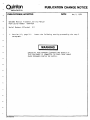
PUBLICATION CHANGE NOTICE
instrument co.
DATE:
PUBLICATION(SJ AFFECTED:
May 2, 1984
Q55/Q65 Medical Treadmill Service Manual
Publication Number
0208-830
Serial Numbers Affected:
1.
Section 2.4, page 2-1.
paragraph:
All
Insert the following warning preceeding the step 2
I WARNING I
EXCESSIVE RISK CURRENT (LEAKAGE) MAY RESULT IF
THIS EQUIPMENT IS CONNECTED TO OTHER THAN SINGLE
PHASE GROUNDED CENTER TAP SUPPLY.
Qr02 -0029 lOB)
TABLE OF CONTENTS
SECTION 1. INTRODUCTION
-
1.1
1.2
1.3
1.3.1
1.3.2
1.3.3
1.4
1.5
1.6
1.6.1
1.6.2
SCOPE ....................................................................................................................... 1-1
ORGANIZATION ..•..•.•...•.•.••.••••..••••••••..•.......•....••.....•..•.• 1-1
Q55/Q65 PRODUCT DESCRIPTION •••••••••••••••••••••••••••••••••••••••••••• 1-1
Q2000 Stress Test Monitor ....................................................................................................... 1-1
Mode1645 Programmable Treadmill Controller ••••••••••••••••••••••••••••••••••• 1-2
Treadmill Controller .................................................................................................................. 1-2
TREADMILL CONTROLLERS ............................................................................ 1-2
ACCESSORIES ........................................................................................................................... 1-2
.1-2
OPTIONS .....••...•••••....•.••••••••••••••••••....•.....•.............
............................................................
1.7.2
1.8
.1-2
Power Options
Hardware Options (Q55/Q65) .....•....•..••..••..•............................ 1-3
.1-3
SPECIFICATIO NS ...•..•.••.••••.••••••.•.••••••.••....
.1-3
Q 55 SpecificatioIlS .••.....•..•.••.••.•.••.••....•.......
Q65 Specifications ...........•.•..••••.••.••..•...•..•....•.....••........... 1-3
OPERATOR MANUAL ••••••••••••••••••••••••••••••••••••••••••••••••••••••• 1-4
1.9
REFERENCES ...•••••••••••••.••••••••••••••.•••.•.••.••••..•..•.......•... 1-4
1.7
1.7.1
SECTIO N 2. OPERA TIO N
2.1
-
2.2
2.3
2.4
...........................................................
...........................................................
INTRODUCTIO N
.2-1
• 2-1
RECEIVING •••••
UNPACKING AND INSPECTION •••••••••••••••••••••••••••••••••••••••••••••• 2-1
INSTALLATION CHECKOUT PROCEDURE ••••••••••••••••••••••••••••••••••••• 2-1
SECTION 3. THEORY OF OPERATION
-
3.1
3.2
3.3
3.4
3.5
3.5.1
3.5.2
3.5.3
3.5.4
3.6
3.7
3.8
3.9
-
3.10
3.11
INTRODUCTION ..•••.••...•....•.••.••••.••••.•....•.....•..•.••••••.•••••• 3-}
PRINTED CIRCUIT BOARD (PCB) ••••••••••••••••••••••••••••••••••••••••••••• 3-1
PO WER S U PPL Y .•••.•.....••.•••••••••••••.....••.•.......••.••.••.•....•••• 3-}
DRIVE MOTO R ..•..•..••.•..•••••••.•...•••..•.•.•..•.....•..•.••••••••••••. 3-3
INPUT SHAFT, OUTPUT SHAFT, BELTS A ND PULLEYS
••••••••••••••••••••• 3-3
Input Shaft. . . . . . . . . . . . • . . . . . • . . . . . . . . . . . . . . . . . . . . . . .
. .....•...•..•••.••.. 3-4
Output Shaft .........•.•..•........•..............................•...•..... 3-4
Variable Speed Belt .......•.....•.•........................•..••.••..••...... 3-4
. ............. . 3-4
Treadmill Drive and Idler Pulleys ••••••••••••••••••••••••••••
.
.............• 3-4
WALKING BELT AND BELT TRACKING SWITCHES ••••••••••
SPEED CHANGE MOTOR ASSEMBLY •••••••••••••••••••••••••••••••••••••••••• 3-5
TACHOMETER ASSEMBLY
....................... . 3-5
GRADE MOTOR ...•••••••.••••••••••••••...••••
. ................. . 3-5
PINION SHAFT AND RACK GEARS •••••••••••••
· ....................... . 3-5
GRADE POTE NTIO METER ••••••••••••••••••••••
· ....................... • 3-5
......................
·.....
SECTION 4. TROUBLESHOOTING
4.1
4.2
4.3
INTRODUCTIO N •.••••••.•••••••••••••••••....•.••.••....•.....•••..•...•.•• 4-1
DIAG NOSTIC AIDS •••.••.•••••••••..•.••••••••••••.......•..•.•..•...•..•••. 4-1
TROUBLESHOOTING PROCEDURE •••••••••••••••••••••••••••••••••••••••••••• 4-1
SECTION 5. CORRECTIVE MAINTENANCE
5.1
5.2
5.2.1
5.2.1.1
5.2.1.2
5.2.1.3
5.2.1.4
5.2.1.5
5.2.1.6
5.2.1.7
5.2.1.8
5.2.1.9
5.2.2
5.2.2.1
5.2.2.2
5.2.2.3
5.2.2.4
5.2.2.5
5.2.3
5.2.3.1
5.2.3.2
5.2.3.3
5.2.3.4
5.2.3.5
5.2.4
5.2.4.1
5.2.4.2
5.2.4.3
5.2.5
5.2.6
5.2.6.1
5.2.6.2
5.2.6.3
5.3
5.3.1
5.3.2
5.3.3
5.3.4
5.3.5
5.4
5.4.1
5.4.2
5.4.3
5.4.4
5.5
INTRODUCTION •••••••••••••••••••••••••••••••••••••••••••••••••••• " •••••• 5-1
DISASSEMBL Y AND REASSEMBLY PROCEDURES •••••••••••••••••••••• '••••••• 5-1
Access Under the Treadmill Hood ••••••••••••••••••••••••••••••••••••••••••••• 5-1
Drive Motor 2M2 Replacement ••••••••••••••••••••••••••••••••••••••,•••••• a_* .5-1
Speed Change Motor 2A2 Replacement •••••••••••••••••••••••••••••••••••••••• 5-1
Speed Change Motor Capacitor 2A2Cl Replacement ••••••••••••••••••••••••••••• 5-2
Tachometer 2A3 Optical Sensor Replacement ••••••••••••••••••••••••••••••••••• 5-2
Tachometer Beam Chopper Replacement ••••••••••••••••••••••••••••••••••••••• 5-2
Grade Motor 2Ml and/or Grade Motor Gearbox Replacement ••••••••••••• ~ ••••••• 5-2
Grade Potentiometer 2RI Replacement •••••••••••••••••••••••••••••••••••••••• 5-3
Printed Circuit Board (PCB) 2Al Replacement ••••••••••••••••••••••••• , •••••••• 5-4
Drive Motor Contactor 2Kl Replacement •••••••••••••••••••••••••••••••••••••• 5-4
Disassembly to Remove the Input Shaft Assembly ••••••••••••••••••••••••••••••• 5-4
Input Shaft Assembly Replacement •••••••••••••••••••••••••••••••••••••••••••• 5-4
Replacement of a Seized Bearing on the Input Shaft ............................... 5-5
Reinstallation of a Loose Bearing on the Input Shaft •••••••••••••••••••••••••••••5-6
Speed Change Spindle Assembly Replacement. •••••••••••••••••••••••••••••••••• 5-6
V-Belt and/or Machined Pulley Replacement •••••••••••••••••••••••••••••••••••• 5-6
Disassembly to Remove the Output Shaft Assembly ••••••••••••••• ~. ir~ ~:.;~ tl' ••• "~ ••. 5~6,\
Output Shaft Assembly Replacement ••••••••••••••••••••••••••••••' .'~,,: ~ :c••• ; • ~ 5~7 ...
Replacement of a Seized Bearing on the Output Shaft ••••••••••••• .,. ••••••• ·••••• 5-7
Reinstallation of a Loose Beari ng on the Output Shaft •••••••••••••••• ~ •••••••••• 5-7
Variable
Speed Belt Replacement ••••••••••••••••••••••••••••••••• ~ '.,-.':' •••••••• 5-8
.
'.
Tl ming Belt Replacement •••••••••••••••••••••••••••••.••••••••• ~ .:••••••••.•• 5-8
Disassembly to Remove the Rack Gears or Pinion Shaft •••••••••••••••••••••••••• 5-8
-
Rack Gear Reassembly •••••••••••••••••••••••••••••••••••••••••••••••••••••• 5-8
Replacement of a Jammed Rack Gear •••••••••••••••••••••••••.•••••••••••••••• 5-9
Pinion· Shaft Replacement •••••••••• e •• ·• • • • • • • • • • • • • • • • • • • e • • • • • • • • • • • • • • • • • • • • 5~9
Belt Tracking Switch Replacement •••••••••••••••••••••••••••••••••••••••••••• 5-10
Disassembly to Remove the Walking Belt or Drive or Idler Pulley •••••••••••••••••• 5-10
Walking Bel t Replacement ••••••••••••••••••••••••••••••••••••••••• ~ • ~ ••••••• 5-10
Drive or Idler Pulley Replacement •••••••••••••••••••••••••••••••••••••••••••• 5-10
Removing a Burr from the Deck •••••••••••••••••••••••••••••••••, • -.'fr "', ~,.'., • • • • t 5-1 0
ADJUSTMENT AND ALIGNMENT PROCEDURES •••••••••••••••••••':~ •••••••••'5-11
Timing Belt Tension Adjustment •••••••••••••••••••••••••••••••••••••• ~ ••••••• 5-11
Walking Belt Tension or Track Adjustment ••••••••••••••••••••••••••••••••••••• 5-11
Adjusting the Setscrews on the Speed Change Yok e •••••••••••••••••••••••••••••• 5-11
Torque Limiter ,Adjustment ••••••••••••••••••••••••••••••••••••••••••••••••••• 5-12
Tachometer Beam Chopper Alignment ••••••••••••••••••••••••••••••••••••••••• 5-12
CALIBRATION PROCEDURES ••••••••••••••••••••••••••••••••• '•••••••••••••• 5-13
Speed Calibration ••••••••••••••••••••••••••••••••••••••••••••••••••••••••••• 5-13
Grade Calibration ........................................................... 5-14
Trip Level.(Low Volts) Calibration ••••••••••••••••••••••••••••••••••••.•••••••• 5"-15
Grade Potentiometer Calibration •••••••••••••••••••••••••••••••.•••••••••••••• 5-15
. POST-MAINTENANCE PROCEDURE ••••••••••••••••••••••••••••••••••••••••• 5-15
SE CTIO N 6. D RA WI NGS •••••••••••••••••••••••••, •••••••••••••••••••••••••••••••••••• 6-1
LIST OF FIGURES
Figure
Figure
Figure
Figure
Figure
Figure
Figure
Figure
Figure
1-1
1-2
1-3
3-1
3-2
3-3
4-1
5-1
5-2
Table 3-1
-
System Q (Q2000 with Q55) ............................................... 1-1
Model 645 Programmable Treadmill Controller •••••.•••••••••••••.••••.•••• 1-1
Q65 with Treadmill Controller, PIN 14544-002 .•••.••••••••••••.•.••••••••. 1-2
Q55/Q 65 Medical Treadmill Components ••••••••••••••••••••••••••••••••••. 3-2
Q55/Q65 Medical Treadmill Functional Block Diagram •••••..••.••••••••••••• 3-7
Input Shaft, Output Shaft, Belts and Pulleys ••••••••••••••.•••••••••...••••• 3-3
Waveform at 2AIP7, Pin 1 ............................................... 4-18
Loosening the Variable Speed Belt •••••••••.••••••••.••••••••••.•••••••••• 5-5
Speed Change Spindle Assembly· •••••••••.•••••••••••••••••••••••••••••.•• 5-11
Drive Motor Specifications ............................................... 3-3
Thank you for purchasing this product from Quinton Medical Co.
With proper care and operation, it will provide outstanding
performance, both now and in the years to come.
To assure safe operation and efficient use of your time, please read
the entire operator manual before operating the equipment.
If you have questions or problems regarding either operation or
service, please contact your local representative or our Seattle
office.
If you discover damage to your equipment, refer to Section 2 for
instructions on damaged shipments and freight claims.
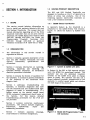
SECTION 1. INTRODUCTION
055/065 PRODUCT DESCRIPTION
The Q55 and Q65 Medical Treadmills are
designed to function as Unit 2 of Quinton's Q
Series of stress test products. One of the
following Quinton instruments functions as
Unit I, the treadmill controller.
1.1
-
1.3
SCOPE
This service manual includes information on
how to install and maintain Quinton's Q55 and
Q65 Medical Treadmills. The manual does not
include information regarding any of the three
treadmill controllers that can be used with the
treadmill: the Q2000 Stress Test Monitor (PIN
0207-001 through 0207-006), the Model 645
Programmable Treadmill Controller (PIN
0222-001 through 0222-003) or Quinton's
Treadmill Controller (PIN 14544-001 or -002).
1.2
1.3.1
02000 Stress Test Monitor
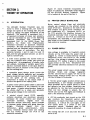
In Quinton's System Q, the treadmill is a
peripheral to the Q2000 Stress Test Monitor.
Figure 1-1 shows the System Q (Q2000 with
Q55).
ORGANIZATION
The information in this service manual is
organized as follows:
Sect ion 1 contains a general description of the
Q55 and Q65 Medical Treadmills and lists
options,
accessories,
specifications
and
references.
-
Section 2 contains information on rece lYIng,
uncrating, inspecting and installing the
Q55/Q65 Medical Treadmill. An installation
checkout procedure is included.
Section 3 contains the theory of operation for
the Q55/Q65. It contains a general description
of the treadmill to the functional block
diagram level.
Section
Figure 1-1
System 0 (02000 with 055)
In System Q, the Q55 or Q65 depends entirely
upon the Q2000 for operational control. The
operator can use the dedicated treadmill
controls on the Q2000 front panel to change
speed or grade. The operator can also use a
stored treadmill protocol, programmed by the
operator, to control speed, grade and duration
for each stage of the protocol.
4
addresses troubleshooting the
It describes diagnostic aids built
into the treadmill unit and includes fault logic
diagrams to assist in troubleshooting. If a
failure occurs on the printed circuit board
(PCB), component replacement should occur at
the factory.
For this reason, detailed
troubleshooting procedures for the PCB are
not provided.
Q55/Q65.
Section 6 contains corrective maintenance
procedures. The section includes alignment,
adjustment,
disassembly,
repair
and
reassembly procedures.
Section
7 contains assembly drawings,
cross-indexed to reference designations.
Figure 1-2
Model 645 Programmable Treadmill Controller
1-1
1.3.2
Model 645 Programmable Treadmill
Controller
Quintons Model 645 Programmable Treadmill
Controller (PTC) can also be used to run the
Q55
or
Q65.
The
645
PTC
is a
microprocessor-controlled system that can
automatically control the Q55 or Q65 during a
stress test. The 645 PTC can store up to 12
protocols, two of which are permanently
stored. The other 10 protocols can be
programmed by the operator. Controls on the
645 PTC also allow manual control of the
treadmill. The 645 PTC displays metabolic
information as well as speed and grade
indication. Figure 1-2 shows the Model 645
Programmable Treadmill Controller.
1.3.3
645 Programmable Treadmill Controller
Handrail Mount
0222-001
Table Top
0222-002
Rack Mount
0222-003
Treadmill Controller
Q55 Treadmill
Q65 Treadmill
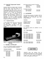
1.5
14544-001
14544-002
ACCESSORIES
The following accessories are shipped with the
Q55/Q65.
Your Quinton sales or service
representative will inventory these items
during installation.
Accessory
Part Number
Handrail Assembly
Handgrip, Fabric
Operator Manual
12976-001
13802-001
0208-841
Treadmill Controller
A third control device that can be used with
the
Q55/Q65
is
Quinton's
Treadmill
Controller. Figure 1-3 shows the Q65 with
the
Treadmill
Controller.
In
this
configuration, treadmill control is totally
manual.
1.6
OPTIONS
The following options are available for the
Q55/Q65:
1.6.1
Power Options
Q55 Option
230V,
230V,
100V,
100V,
208V,
l15V,
60Hz,
50Hz,
60Hz,
50Hz,
60Hz,
60Hz,
Part Number
Single
Single
Single
Single
Single
Single
phase
phase
phase
phase
phase
phase
Q65 Option
Figure 1-3
1.4
065 with Treadmill Controller, PIN
14544-002
230V, 60Hz, Single phase
208V, 60Hz, Single phase
0208-001
0208-002
0208-003
0208-004
0208-005
0208-006
Part Number
0221-001
0221-005
TREADMILL CONTROLLERS
Any of the following treadmill controllers can
be used to operate the Q55/Q65 treadmill.
Treadmill Controller
Q2000 Stress Test Monitor
230V, 60Hz
230V, 50Hz
100V, 60Hz
100V, 50Hz
208V, 60Hz
115 V, 60Hz
1-2
Part Number
0207-001
0207-002
0207-003
0207-004
0207-005
0207-006
Treadmill users
are
advised
that an
autotransformer should not be used to increase
115 Vac to 230 Vac to run the treadmill.
Consult your local licensed electrician to
correct the voltage at your facility.
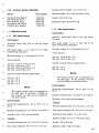
1.6.2
Hardware Options (a55/a65)
Walking surface height: 5.3 in (13.5 cm)
Option
Part Number
Handrail height: 43 in (l09 cm) above floor
Overhead Mask Support
Side Handrail, Short
Side Handrail, Long
Emergency Off Switch
Ca theter Arm Support
13689-001
13690-001
13691-001
13675-001
0043-002
Weight: 400 lb (l81 kg)
Shipping weight: 500 Ib (227 kg)
1.7.2
1.7
SPECIFICATIONS
1 .7.1
Perf ormance
a55 Specifications
Performance
Maximum rated load: 400 Ib (l81 kg), Bruce
Protocol
Maximum rated load: 350 Ib (159 kg), Bruce
Protocol
Belt speed range: 1.5 to 15 mph (2.4 to 24
kph), continuously adjustable
Belt speed range: 1 to 10 mph (1.6 to 16 kph),
continuously adjustable
Elevation range: 0 to 2596 grade (0 to 14°)
Elevation range: 0 to 2596 grade (0 to 14°)
Power options:
-
a65 Specifications
100
115
230
208
Vac,
Vac,
Vac,
Vac,
1 PH,
1 PH,
1 PH,
1 PH,
50
60
50
60
or 60 Hz, 24 A
Hz, 24 A
or 60 Hz, 12 A
Hz, 12 A
Power options:
230 Vac, 1 PH, 60 Hz, 16 A
208 Vac, 1 PH, 60 Hz, 16 A
Minimum branch circuit requirements:
230 Vac - 20 A
208 Vac - 20 A
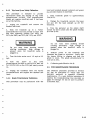
NOTE
Minimum branch circuit requirements:
The branch circuit must be dedicated to
the Q65 only. Do not connect the Q65
and the Q2000 to the same circuit.
100 Vac - 30 A
115Vac-30A
208 Vac- 15 A
230 Vac-15 A
Environmental
NOTE
-
The branch circuit must be dedicated to
the Q55 only. If used with a Q2000, do
not connect the Q55 and the Q2000 to
the same circuit.
60 to 95°P (I5 to
Storage temperatures: 0 to 1200 P (-18 to 49°C)
Humidity: 30 to 9096, noncondensing
En vironmental
Physical
Operating temperatures:
35°C)
--
Operating temperatures:
35°C)
60 to 95°P (15 to
Nominal walking area: 20 x 65 in (51 x 165 cm)
Storage temperatures: 0 to 120 0 P (-18 to 49°C)
Ploor space required: 28 x 86 in (71 x 218 c m)
Humidity: 30 to 9096, noncondensing
Walking surface height: 5.3 in (13.5 cm)
Physical
Handrail height: 44 in (Ill cm) above floor
Nominal walking area: 20 x 55 in (51 x 140 cm)
Weight: 425 Ib (193 kg)
Ploor space required: 28 x 76 in (71 x 193 cm)
Shipping weight: 600 Ib (272 kg)
1-3
1.8
OPERATOR MANUAL
A comprehensive operator manual is supplied
with this equipment.
You may order
additional copies by writing to Quinton
Instrument Company, 2121 Terry Avenue,
Seattle, Washington 98121; or by calling our
Customer Service Department at (800)
426-0347.
1.9
REFERENCES
The following references were used in the
preparation of this manual:
1. Operator manual for the Model Q55/Q65
Medical Treadmill, PIN 0208-841
2. Operator manual for the Quinton Model
Q2000 Stress Test Monitor, PIN 0207-840
3. Service manual for the Quinton Model
Q2000 Stress Test Monitor, PIN 0207-830
4. Technical
Programmable
0222-830
1-4
manual for the Model 645
Treadmill Controller, PIN
SECTION 2. OPERATION
3.
Cut the bands.
4. Lift the top of the crate straight up off
the pallet.
5.
2.1
INTRODUCTION
This section contains the reCeIVing, unpacking
and inspection, and installation procedures.
2.2
6. With the aid of a second person, lift the
flat end of the treadmill no more than 6 inches
off the pallet.
RECEIVING
Before leaving the factory, the Q55/Q65 is
thoroughly inspected and tested for proper
operation. To minimize shipping damage, the
Q55/Q65 is shipped in a specially designed
packing crate. The Q55 weighs 500 lb. (272
kg) and the Q65 weighs 600 lb. (272 kg).
-
Lifting from the wrong end of the
treadmill or lifting more than 6 inches off
the pallet or floor can damage the
treadmill.
Quinton Instrument Company's responsibility
for this shipment ends upon delivery to the
carrier, who assumes responsiblity for safe
delivery. Therefore, when damage or loss to
merchandise shipped FOB Factory is sustained
in transit, claims must be made by the
customer and directed to the carrier.
Limit switches on the underside of the
treadmill can break if the treadmill is not
lifted carefully off the pallet.
When shipments are sent FOB Destination,
Quinton Instrument Company will file the
claim, provided we are furnished with an
acceptable inspection report from the carrier.
If a claim is disallowed because of failure to
obtain the report, repair charges will be billed
to the customer.
7. Ease one of the front wheels off the
pallet.
Upon receipt of the shipment, the containers
or units should be inspected for external
damage. Discrepancies should be noted on the
waybill, which should then be signed by the
carrier's agent. Failure to adequately describe
external evidence of loss or damage on the
waybill may result in the carrier refusing to
honor the claim.
10. Install the handrail by positioning on the
two supports provided on the headframe.
2.3
8.
Ease the second wheel off the pallet.
9. Roll
position.
2.4
the
treadmill
into
the
desired
INSTALLATION CHECKOUT PROCEDURE
WARNING
I
UNPACKING AND INSPECTION
The front handrail assembly and the operator
manual arc shipped with the Q55/Q65 Medical
Treadmill as standard equipment. These items
are not listed on the waybill.
-
Remove the plastic sheeting.
Do not start
standing on it.
belt
when
anyone
is
1. Inspect the shipping crate for evidence of
damage.
1. Verify that the service outlet voltage
matches the voltage on the nameplate. If
using the Q2000 as the treadmill controller,
verify that the treadmill alld the Q2000 are on
separate branch circuits.
2. Pull the nails out of the lower skirting of
the crate.
2. Plug the Q55/Q65 power cord into the
service outlet.
2-1
3. Inspect treadmill connector 2A4W2Jl for
damage, then connect the control cable (PIN
13102-001) •
through the entire range specified for
both speed and grade.
g.
4. If using the Q2000 as the treadmill
controller, perform the following steps. If no
error codes appear during performance of the
test, the treadmill is operational.
a.
Ensure that the checkout procedure in
Section 2.3 of the Q2000 Operator Manual
(P IN 0207-840) has been performed.
b.
Run treadmill calibration (Steps 1, 2 and 7
of Section 4.4 of Q2000 Service Manual)
and store data.
c.
Press MASTER RESET.
d.
If AUTO TM red LED is on, press AUTO
Press STOP and verify that treadmill
stops.
Programmable
5. If using Model 645
Treadmill
Controller as
the
treadmill
controller, perform the checkout procedure in
Section 2.3 of the Model 645 Programmable
Treadmill Controller Technical Manual (PIN
0222-830).
6. If using Quinton's Treadmill Controller,
perform the following steps.
a.
Ensure that CABLE CO N N LED is on.
b.
Press RUN to start the treadmill.
manual
c.
e.
Press START.
Using SPEED and ELEV (grade) increase
and decrease keys, verify that the
treadmill can be controlled manually
through the entire range specified for
both speed and grade.
f.
Using speed and grade, increase and
decrease (...... and".) controls. Verify that
the treadmill can be controlled manually
d.
Press STOP and verify that treadmill
stops.
TM to return
operation.
2-2
treadmill
to
SECTION
3.
,
THEORY OF OPERATION
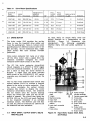
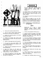
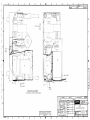
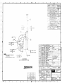
Figure 3-1 shows treadmill components and
figure 3-2 shows the functional block diagram
for the Q55/Q65 Medical Treadmill. Figure
3-2 is located at the end of Section 3.
3.2
3.1
-
The Q55/Q65 Medical Treadmill uses one
motor to drive a walking belt, one motor to
change the speed of the walking belt and one
motor to change the grade (elevation) of the
treadmill.., The treadmill is considered Unit 2
of Quinton's Q Series of stress test products.
It can be controlled by any of the following
treadmill controllers (the controller is
considered Unit I): the Q2000 Stress Test
Monitor, the Model 645 Programmable
Treadmill Controller or Quinton's Treadmill
Controller. The Q55 and Q65 are functionally
identical and use identical cable interfaces to
the various types of controllers. The Q55
operates between I and 10 mph (l.6 and 16
kph), and the Q65 operates between 1.5 and 15
mph (2.4 and 24 kph).
A drive motor provides the motive force to
turn the treadmill drive pulley and move the
walking belt. An arrangement of shafts, belts
and pulleys, including a variable speed belt,
allows a moveable sheave on the input shaft to
affect the rate of rotation of the output shaft
and the walking belt.
A reversible speed change motor moves the
speed change spindle assembly and moveable
sheave along the input shaft to effect changes
A
in the speed of the walking belt.
tachometer is linked to the output shaft to
monitor the speed of the walking belt.
-
-
PRINTED CIRCUIT BOARD (PCB)
INTRODUCTION
A grade motor turns a pinion shaft to raise and
lower the headframe of the treadmill on two
x:ack gears. A grade potentiometer linked to
the pinion shaft by a chain and sprockets
allows grade change to be monitored.
A printed circuit board (PCB) assembly
contains electrical and electronic elements
necessary for motor control and treadmill
controller interface.
Signals from
the
controller initiate start/stop, speed increase
or decrese, grade change and grade direction
change.
Feedback
signals
from
the
tachometer,
grade
potentiometer,
drive
motor, treadmill control cable and walking
belt are routed through the PCB to the
treadmill controller.
Motor control relays, fuses and electronic
circuits are mounted on the printed circuit
board (PCB) 2Al. Mounted on the back of the
PCB bracket are drive motor contactor 2Kl
and transformer 2Tl. Connector 2AIPll on
the PCB provides the interface between the
treadmill controller (Unit I) and the treadmill
(Unit 2). Circuits on the PCB and electrical
components are described in this section as
they relate to the treadmill subassemblies that
they control or monitor.
3.3
POWER SUPPLY
Line voltage is available to treadmill control
circuits on the PCB when the power cord is
plugged in. Power is routed directly through
connectors 2AIPI and 2AIP6 to the motors
and fan. Line voltage is stepped down through
transformer 2Tl before it goes to the power
supply circuit on the PCB. Transformer 2Tl
also provides electrical isolation from primary
power.
The power supply circuit uses a diode bridge
rectifier, filters and voltage regulators
2Al VR I and 2Al VR2 to supply +24 Vac to the
power supply monitor circuit and +12 Vdc and
+23 Vdc to other PCB circuits.
A +24 Vac power supply monitor circuit uses a
rectifier/filter, a low voltage comparator, a
pulse stretcher and an output driver to sense
and indicate low line voltage. Sensitivity can
be adjusted by the trip level potentiometer.
When .low line voltage is sensed, the LO
VOLTS LED on the PCB lights and feedback is
sent to the treadmill controller.
A +23 Vdc continuity test circuit on the PCB
also monitors the treadmill control cable
connection to ensure that there is no break in
continuity. A CABLE OK LED lights on the
PCB unless there is a break in the plug
connection circuit. Feedback goes to the
treadmill controller if a break is detected.
The cooling fan 2Fl is on any time the drive
motor is on.
3-1
5
6 7 8 9 10 11 12 13
..........----14
4-----
---15
--16
------17
3--2----r-
--18
1---+
----20
19
1 Headframe
2 Tachometer
assembly
3 Drive motor
4 Printed circuit board
5 Grade motor
6 Grade potentiometer
7 V-belts
8 Pinion shaft
9 Cooling fan
10 Input shaft
Figure 3-1
3·2
11
12
13
14
15
16
17
18
19
20
Fixed sheave
Variable speed belt
Moveable sheave
Rack gear
Speed change
spindle assembly
Speed change motor
Timing belt
Output shaft
Drive pulley
Walking belt
055/0S5 Medical Treadmill Components
Table 3-1
Drive Motor Specifications
QUINTON
PART
NUMBER
USED
ON
VOLTAGE
13657-001
Q55
208-240 Vac
13657-002
Q55
13657-003
FREQUENCY
(SINGLE
PHASE)
FULL
LOAD
INSULATIO N
CURRENT CLASS
HP
FULL
LOAD
RPM
60 Hz
1 1/2
1725
7 1/2 amps
B
Resilient
110-120 Vac
60 Hz
1 1/2
1725
15 amps
B
Resilient
Q55
200-240 Vac
50 Hz
1 1/2
1425
8 amps
B
Resilient
13657-004
Q55
100-120 Vac
50 Hz
1 1/2
1425
16 amps
B
Resilient
14560-001
Q65
208-240 Vac
60 Hz
3
3540
15 amps
B
Solid Base
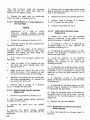
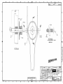
3.4
DRIVE MOTOR
The drive motor 2M2 provides the motive
force to turn the treadmill drive pulley and
move the walking belt. Table 3-1 shows motor
specifications for different motors used in the
Q55 and Q65. All are continuous duty, single
phase motors that have internal overload
protection.
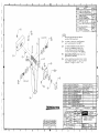
An input shaft, an output shaft, belts and
pulleys function as a transmission on the
3-3
illustrates
this
Q55/Q65.
Figure
arrangement.
The
following
paragraphs
describe shaft, belt and pulley operation in
detail.
7
n
Drive motor contactor 2K 1 turns on or shuts
off the drive motor when a signal from the
treadmill controller energizes the motor
contactor driver latch circuit on the PCB.
The +23 Vdc motor contactor driver/latch
circuit responds to a START or STOP signal
from the treadmill controller. It uses a driver
and a latch to keep the motor started or
stopped. A signal from the motor overload
latch circuit or the EMERGENCY OFF switch
overrides any commands to start or stop the
motor.
The + 12 Vdc motor overload latch circuit uses
optical isolator 2Al U5 to monitor a thermal
sensor in the motor or motor contactor. When
the motor overloads, the optical isolator
actuates this circuit to disable the motor
contactor driver/latch circuit. The treadmill
will not restart until the motor's thermal
sensor has cooled and reset and the START
switch is pressed. The circuit also lights the
MOTOR LED on the PCB and sends feedback
to the treadmill controller if an overload
condition occurs. The MOTOR LED will stay
on until the thermal overload has cleared and
the treadmill has been restarted.
3
--8
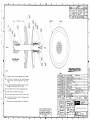
INPUT SHAFT, OUTPUT SHAFT, BELTS
AND PULLEYS
2
;....--9
1
;;..---10
r--o----11
-------12
2
3
4
5
6
7
3.5
MOUNT
Drive motor output
shaft
V-belts
Machined pulley
Input shaft
Input shaft fixed
sheave
Input shaft moveable
sheave
Input pulley
Figure 3-3
14 13
8 Speed change
spindle assembly
9 Variable speed belt
10 Timing belt
11 Output shaft
12 Drive pulley
13 Output shaft fixed
sheave
14 Output shaft
moveable sheave
15 Output pulley
~
15
Input Shaft, Output Shaft, Belts
and Pulleys
3-3
Input Shaft
3.5.1
The input shaft is equipped with a machined
pulley, the fixed and moveable sheaves that
comprise the input pulley, and the speed
change spindle assembly. Two V-belts link the
drive motor output shaft with the input shaft.
The input shaft turns at a fixed rate.
The speed change spindle assembly consists of
a fork, a speed change spindle and a yoke. As
the speed change motor turns the spindle, the
fork moves laterally on the input shaft in
tandem with the moveable sheave. 'The
~unction .o.f the speed change spindle assembly
IS to posItIon the moveable sheave on the input
shaft.
3.5.2
Output Shaft
The output shaft is equipped with a spring, the
moveable and fixed sheaves that comprise the
output pulley, and a timing pulley, The output
shaft turns at a variable speed depending on
the pitch diameter of the output pUlley.
3.5.3
Variable Speed Belt
A variable speed belt links the input pulley and
the output pulley. Because the four sheaves in
the arrangement are graded, the variable
speed belt can be forced in or out between
pairs of sheaves to increase or decrease pitch
diameter. Spring tension against the moveable
sheave on the output shaft tends to force the
belt outward, increasing the pitch diameter of
the output pulley. When the speed change fork
moves the moveable sheave on the input shaft
~nward, the pitch diameter of the input pulley
Increases and causes a concurrent decrease in
the pitch diameter of the output pulley. This
turns the output shaft at an increased rate.
3.5.4
Treadmill Drive and Idler Pulleys
The timing pulley on the output shaft drives
the treadmill drive pulley. The drive pulley, in
turn, drives the walking belt and the treadmill
idler pulley.
3.6
WALKING BELT AND BELT TRACKING
SWITCHES
The walking helt is the tread mill conveyor
belt. Two factory-set limit switches on the
underside of the treadmill deck monitor the
lateral movement of the walking belt. If the
walking belt comes close to touching an edge
3-4
of the treadmill drive pulley, one of the
switches actuates. If a switch actuates, the
BELT LED on the PCB automatically lights
and a message is sen t to the treadmill
controller that a hazardous condition exists.
On the Q2000, the message TREADMILL BELT
TRACKING ERROR appears on the screen.
On the 645 PTC, the BELT TRACKING LED in
the SELF TEST box lights. On the Treadmill
Controller panel, the BELT TRACK LED lights.
3.7 SPEED CHANGE MOTOR ASSEMBLY
The speed change motor assembly 2A2 consists
of a reversible, spli t-capacitor gear motor
2A2M I and the speed change capaci tor
2A2CI. The speed change motor is linked by a
chain and sprockets to the speed change
spindle assembly that moves the assembly
laterally along the input shaft. The speed
change capacitor provides the phase shift
necessary to start the motor. The motor
cannot be operated unless the drive motor is
also on.
Relay drivers 2Al V3 on the PCB receive logic
level signals from the treadmill controller and
deliver appropriate voltage to the appropriate
speed change motor relay. Speed change
motor relay 2AIK3 controls speed increse, and
speed change motor relay 2AIK4 controls
speed decrease. Relay 2AIK3 is also a lockout
relay to prevent both relays from energizing
si multaneously.
3.8 TACHOMETER ASSEMBLY
Tachometer assembly 2A3 uses an optical
emitter and a sensor that run on +12 Vdc from
the PCB. The sensor measures the rate of
light beam interruptions caused by a rotating
beam
chopper.
The
resulting
variable
frequency pulses are converted by the
tachometer circuit into a dc voltage
proportional to the speed of the treadmill.
The . tachometer circuit uses frequency
d.oublmg pulse amplifier 2AI VI and a low pass
fIlter (also 2A 1V 1) to convert the variable
frequency
pulses
received
from
the
tachometer. The output of the filter is
l'eferenced to +12 Vdc. The tachometer
current source then changes the voltage signal
to a current signal and transmits the current
signal back to the treadmill controller.
Tachometer
gain potentiometer
2AIR13
allows calibration of the tachometer current
source so that 1 milliampere represents a rate
of 1 mile per hour.
3.9
GRADE MOTOR
Grade motor 2Ml is a right angle gear motor.
The motor shaft is linked to a pinion shaft by a
chain and sprockets. The chain turns a
sprocket on the pinion shaft to raise and lower
the headframe of the treadmill on two parallel
rack gears.
Relay drivers 2Al U3 on the PCB receive logic
level signals from the treadmill controller and
deliver appropriate voltage to grade change
relay 2AIKl or grade direction change relay
2AIK2.
Grade change relay 2AIKl starts or stops the
grade motor. It works with relay 2AIK2 to
increase or decrease grade, depending on the
polarity of the direction control windings.
Grade direction change relay 2A 1K2 controls
the polarity of the direction control windings
in the grade motor. The change in polarity
does not cause the grade motor to turn,
although it alters the direction that the grade
motor shaft will spin. The.2 second delay
circuit on the PCB delays the signal to relay
2AIK2 to ensure that the grade motor stops
completely before changing direction.
3.10
PINION SHAFT AND RACK GEARS
The pinion shaft and rack gears allow the
entire headframe assembly to tilt for grade
increase or decrease. The pinion shaft rotates
two sprockets at either end to move up and
down a parallel pair of rack gears. Mechanical
stops at the top of the rack gears prevent
upward overtravel, while the deck prevents
downward overtravel. The pinion shaft has a
torque limiting device to prevent damage to
the grade motor if it continues to turn at the
upper or lower limits of travel.
3.11
GRADE POTENTIOMETER
Grade potentiometer 2R 1 monitors the
rotation of the pinion shaft to indicate
changes in grade. The potentiometer is linked
to the pin ion shaft by a pair of sprockets and a
chain. The potentiometer runs on +12 Vdc
from the PCB. The voltage signal from the
potentiometer is changed by the grade current
source on the PCB to a current feedback
signal that goes to the treadmill controller.
Grade zero potentiometer 2AIR29 allows
calibration of the grade current source when
the grade angle is zero so that an increase in
voltage represents an increase in grade.
Grade gain potentiometer 2AIR30 allows
calibration of the grade current source so that
a I milliampere change represents a 296
change in grade.
3-5/3-6 Blank
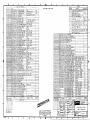
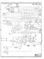
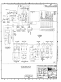
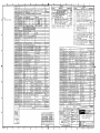
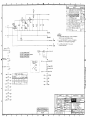
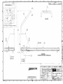
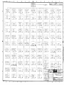
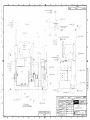
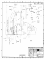
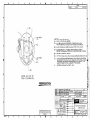
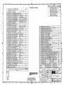
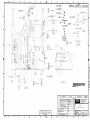
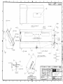
FIGURE 3-2
-
-
-
FUNCTIONAL BLOCK DIAGRAM MAJOR COMPONENTS
PCB
BLOCK
MAJOR COMPONENTS
2AI
Power Supply Circuit
CRI, CR2, CRI7, CR20, VRI,
VR2
Continuity Test Circuit
CR6
Power Supply Monitor Circuit
UI, U3, U4, CR9
Optical Isolator
U5
Motor Overload La tch Circuit
U4, U5, Q5, CRIO
Motor Contactor Driver/Latch Circuit
Q3,Q4
Tachometer Circuit
UI
Tachometer Current Source
U2, Q2
Grade Current Source
U2, QI
.2 Second Delay Circuit
U3, U4
Relay Drivers
U3
Grade Change Relay
KI
Grade Direction Change Relay
K2
Speed Motor Change (Increase) Relay
K3
Speed Motor Change (Decrease) Relay
K4
CABLE OK LED
CR6
LO VOLTS LED
CR9
MOTOR LED
CRIO
BELT LED
CR5
Tachometer Gain Potentiometer
Rl3
Trip Level Potentiometer
R23
Grade Zero Potent iometer
R29
Grade Gain Potentiometer
R30
r
I
TRAW'5FQRMER
2Al
,..
FA"-J
EMERGEl-JCY
OFF
SWITCH
PI!
I
'STOP/START
CIRCUIT
COOLlW~
FROM CO)..JTROLLER
(U)..JIT I)
2Ft
I
~
I
I
I
I
,,2,13,18::>>--+1------
PI
.
POWER
SUPPLY
2.TI
I
I
I
N':.l~£MBLY,
P.C.B.
COt-.JTI)..JUITY
TEST CIRCUIT
1
I
CABLE OK
LED
+24 'lAC
.,(. VDC.
TO COklTROLLER
(U"-lIT I)
,.
I
,.
-'"
LOW VOLTS
LED
I
I
I
,
I
I
MOTOR
~ COkJTACTQP,
[)RIVER/LATCH
CIRCUIT
14
COklTI)..JUITY TE5T
I
... +2.3 VDC.
POWER
SUPPLY
MOkllTOR
CIRCUIT
PH
. 21
LOW AC FAULT
I
PII
I
rRIP LEVEL..
POT
2A\RZ3
PI\
DRIVE
MOTOR
CO"-lTACTOR
UWE VOL..TAGE
MOTOR
DRIVE
MOTOR
2M2
2"'"
OVa~LOAD
)I
LATCH
CIRCUIT
MOTOR
LED
I
.....--r---t-:I)~lq
MOTOR FAULT
I
PII
OPTICAL
ISOLATOR
ZAIU5
IklPUT SHAFT,
OuTPUT SHAF f,
A"-lD PULLEYS
~ ~.
:
l
I
WAU<-IU
BELT
rAC
HOMETER
AGj"=EMBL
Y
2A3
T
I
+12VDC
ZA1R1S
I
~ -
\I
TACHOtv\ETEK
.... TACHOMETER
O"CU'T
I
CURREhJT
'c:>OURCE
7
BELl
BELT
LED
TRAC~lkJG
SWITCHE"J
I
I
I
,:)PEE.D CHA)..JSE: lL
MOTOR
r'
""PEED IWC.REJ>.5E
SPEED DECREASE:.
2/"2-
I
n
15
I
lit
PI'"-JIOU SHAFT
AklD
RACK GEARS
':'
GRADE
MOTO~
v
I'
-- -~
GRADE
POT
<:
,.
.
PI1
4
I
P11
,
,.
2.R\
I
I
It
GRADE
CHAklGE
t::(ELAY
ZAtKl
.2. SECOI....JD
DELAY
CIRCUIT
SPEED FEEDBACK
i,\
J
"
I
I
I
GRADE
CURREWT
SOURCE
PII
I
,
"
10
GRADE FEEDBACK
I
J
GAIt--J
POT
2AtR30
I
PI1
I
,It
J
I
... ,
GRADE CHAI..JGE
i
2AIU3
II'
I
2M!
,
ZERO
POT
2.AI R2.C)
~
...
1
3
i
·12. VDC
~
PII
GRADE DIRECTIOkJ CHAkiGE
2AIK38.2AIK4
I
I""7'
~ 12
PI!
,:)PEEO CHAI..JGE:
MOTOR
I
PII
/---....---11-):;"·2.0 BELT TRACKII..JG
I
I
I
PII
I
GAlkl
POT
I
L-
GRADE
DIRECTIO\..J
CHAkJC:::JE RELAY
2AIK2..
I
I
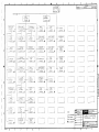
Figure 3-2
.J
Q55/Q65 Medical Treadmill Functional Block Diagram
3-7
SECTION 4. TROUBLESHOOTING
-
4.1
INTRODUCTION
This section contains fault logic diagrams, test
data and waveform graphics to aid in isolating
a malfunction to a faulty component. After a
faulty component has been identified, refer to
Chapter 5 for corrective maintenance
procedures.
If a failure occurs on the printed circuit board
(PCB), component replacement should occur at
the factory.
For this reason, detailed
troubleshooting procedures for the PCB are
not included.
-
-
-
4.2
DIAGNOSTIC AIDS
Each type of treadmill controller incorporates
its own diagnostic aids. Quintonts Treadmill
Controller (PIN 14544-001 or 14544-002) is
the simplest and has four LEOs on the control
panel that correspond to the four LEOs on the
PCB of the treadmill. These LEOs show
status of the belt switches, cable continuity,
voltage to the treadmill and motor overload.
The Model 645 Programmable Treadmill
Controller (645 PTC) also incorporates
diagnostic aids. An automatic initialization
test is conducted any time the treadmill is
turned on or MASTER RESET is pressed, and
information is displayed in the SELF TEST
block of the control panel. In addition, a
treadmill calibration procedure (Section 6.2 of
the 645 PTC Technical Manual) should be
performed at installation, once every six
months and after maintenance is performed.
A complete description of the diagnostic aids
built into the 645 PTC can be found in Section
5.3 of the 645 PTC Technical Manual.
The Q2000's diagnostic aids are described in
Section 4 of the Q2000 Service Manual. The
Q2000
also
conducts
an
automatic
initialization test each time it is turned on or
reset, and error messages are displayed on the
screen. Treadmill calibration (Steps 1, 2 and 7
of Section 4.4 of the Q2000 Service Manual)
should be performed at installation, once
every six months and after maintenance has
been performed.
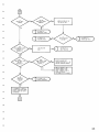
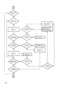
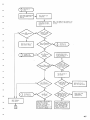
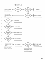
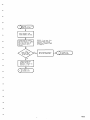
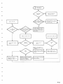
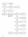
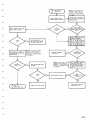
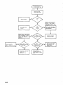
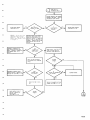
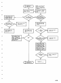
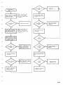
4.3
TROUBLESHOOTING PROCEDURE
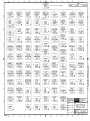
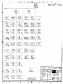
The fault logic diagrams that follow are
designed to lead you through an operability
test of the Q55/Q65 Medical Treadmill. They
aid in isolating a malfunction to the treadmill
or to the treadmill controller. A square on the
diagram indicates a procedural step, and a
diamond on the diagram indicates a decision
point. Figure 4-1 shows the waveform needed
to troubleshoot the tachometer.
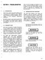
NOTE
Servicing your own equipment while it is
still within the warranty period may void
the warranty.
I
WARNING
To prevent high voltage electrical shock,
unplug the treadmill any time you
remove the hood.
WARNING
I
00 not wear loose clothing when working
around rotating machinery.
~
C
Treadmill users are advised that an
autotransformer should not be used to
increase 115 Vac to 230 Vac to run the
treadmill. Consult your local licensed
electrician to correct the voltage at
your facility.
4-1
START
PLUG IN
POIIE R CORD.
PLUG IN CONTROL
CABLE.
TO PAGE 4-7
Q2000
4-6
CHECK BU I LD I NG
CIRCUIT BREAKER.
RESET BU I LD ING
CIRCUIT BREAKER.
PRESS RUN
PUSHBUTTON.
TO PAGE ~-8
CABLE NOT OK
ELIMINATE OTl!fR LOADS
SO THAT TREADMILL IS
ON A DEDICATED CIRCUIT.
NO
YES
CHECK WITH UTILITY
ABOUT LOW LINE VOLTAGE.
MEASURE VOLTAGE
AT WALL OUTLET.
ADJUST TRIP LEVEL
POTENT IOMETER
(SECTION 5.~.3).
4-2
REFER TO DRAWING #13677
FOR WIRING TO TRANSFORMER
2Tl. WITH TREADMILL
UNPLUGGED, REWIRE TRANSFORMER, THEN ADJUST TRIP
LEVEL POTENTIOMETER 2A1R23
(SECTION 5.4.3)·
NO
ENSURE NO ONE IS ON
THE WALKING BELT.
TO PAGE 11-10
OVERLOAD CAUSE
TO PAGE 11-11
MOTOR LED FAULT
STOP WALKING
BEL T.
-
TO PAGE 1,-13
BELT TRACKING
NO
ADJUST WALKING BELT
TENSION (SECTION 3.2.1 OF
Q55/Q65 OPERATOR MANUAL).
UNPLUG TREADMILL ANO
REMOVE HANORAIL AND
HOOD. INSPECT V-BELTS.
All GN OR REPLACE
(SECTION S.2.2.5) V-BELT.
TO PAGE ~-1~
NOISY OPERATION
-
IF TREADMILL IS NOT AT
MINIMUM SPEED AND GRADE,
REDUCE SPEED AND GRADE
TO MINIMUM.
-
4-3
ADJUST SETSCREWS ON
SPEED CHANGE YOKE
(SECTION 5.3.3).
I NCREASE SPEED
TO MAXIMUM.
UNPLUG TREADMILL, REMOVE
HANDRAIL AND HOOD AND
SPEED CHANGE
MOTOR AND SPINDLE ASSEMBLIES
FOR LOOSE PARTS OR DAMAGE.
">..:.:.=-_______ ... INSPECT
~
TO PAGE 4-15
SPEED FAULT
TO PAGE ~-17
TACHOMETER fAULT
CALI BRATE SPEED
(SECTION 5.I,,1).
DECREASE SPEED
TO MINIMUM.
YES
4-4
INCREASE GRADE
TO MAXIMUM.
TO PAGE 4-19
GRADE FAULT
.CALI BRATE GRADE
(SECTION 5.4.2).
-
RESTORE POWER TO TREADMILL
AND ~ATCH TORQUE LIMITER
AS YOU CHANGE GRADE.
UNPLUG TREADtiILL AND
REMOVE HANDRAIL AND
HOOD.
Do not wear loose
clothing aro"nd rotating
machi nery. High vol tage is
present when treadmill cable
is plugged in.
~ARNING:
REALIGN GRADE
MOTOR SPROCKET.
NO
-
DECREASE GRADE
TO MINIMUM.
ADJUST TORQUE LIMITER
(SECTION 5.3 . .4).
YES
NO
TO PAGE 4-19
GRADE FAULT
REPLACE DAMAGED RACK
GEAR (SECTION 5.2.".1).
-
4-5
PRESS POWER PUSHSUTTON
AND VER I FY THAT POWE R
LEO COMES ON.
ENTER OPEN LOOP 1'I00E BY
PRESS ING MASTER RESET
ANO HOLDING THE TM CAL
PUSHBUTTON UNT IL ALL TH E
8's DISAPPEAR fROM THE
DISPLAY.
REFER TO SECTION 5.3 OF
MODEL 645 PROGRAMMABLE
TREAOMILL CONTROLLER
TECHNICAL MANUAL.
TO PAGE 4-10
OVERLOAO CAUSE
TAKE GRADE TO MAX UIUM
AND INSPECT BELT TRACKING
SWITCHES. ADJUST BELT
TRACKING SWITCH LEVER ARM
IF OUT OF ADJUSTMENT.
REPLACE SWITCH (SECTION
5.2.5) If LEVER ARM IS
BROKEN.
TO PAGE 4-8
CABLE NOT OK
YES
4-6
PRESS POWER
VERI FY THAT
COKES ON.
-
P~ESS
~.ASTER
RESET
PUSHBUTTON.
ENTER OPEN LOOP HODE
BY PRESSING 9, TijEN 5,
THEN I.
NOTE: The Q2000 and the treadmi 11 must
operate on separate, ded i cated branch
circuits.
NO
TO PAGE 4-8
CABLE NOT OK
REFER TO SECTION 4 OF
Q2000 SERVICE MANUAL
ELIMINATE OTHER LOADS
SO THAT TREADMI LL IS ON
II DEDICATED CIRCUIT.
TO PAGE 4-10
OVERLOAD CAUSE
MEASURE VOLTAGE AT
WALL OUTLET.
CHECK WITH UTI LIn
ABOUT LOW LI NE VOLTAGE.
ADJUST TRI P LEVEL
POTENT IOMETER
(SECTION 5,'.3).
TO PAGE 4-13
BELT TRACKING
PRESS TREADMILL
START SWI TCH
-
TAKE GRADE TO MAX IMUH AND
INSPECT BELT TRACKING
SWITCHES. ADJUST BELT
TRACKING SWITCH LEVER ARH
I F OUT OF ADJUSTMENT.
REPLACE SIiITCH(SECTION 5.2.5)
IF LEVER ARM IS BROKEN.
REFER TO DRAW I NG #13677 FOR
IIIRING TO TRANSFORMER 2TI.
III TH TREADH I LL UNPLUGGED,
REIII RE TRANSFORMER, THEN
ADJUST TRIP LEVEL POTENTIOMETER (SECTION 5.4.3).
4-7
STOP THE TREADMILL AND
PULL THE POWER CORD
REMOVE HANDRAI LAND
HOOD. CHECK FUSES
2AIFI and 2A1F2.
NO
REPLACE BLOWN FUSE.
PLUG IN 2A1Pll
SECURELY.
RESTORE POWER TO THE
TREADMILL. MEASURE OUTPUT
VOLTAGE AT TRANSFORMER 2Tl
FOR 24 VAC !S%.
GROUND
2AIR26
2A1Pl1
OK LED
FAULT IS IN A
TREADMILL CONTROLLER
C I RCU IT.
4-8
YES
WARNING: High vol tage is
present when treadmill cable
is plugged in.
NO
REPLACE TRANSFORMER
2T1.
NO
REPLACE PCB
(SECTION 5.2.1.8).
RIGHT SIDE OF
OR PIN 14 OF
AND SEE IF CABLE
COMES ON.
NO
ADJUST WALKING BELT TENSION
(SECTION 3.2.1 OF Q55/Q65
OPERATOR MANUAL).
TIGHTEN BOLTS.
UNPLUG TREADMILL AND
REMOVE HANDRAIL ANO HOOO.
CHECK FOR DAMAGED INTERNAL
BELT.
HS
ADJUST TIMING BELT TENSION
5.3.1) OR REPLACE
TIMING BELT (SECTION 5.2.3.5)
NO
MOVEABLE SHEAVE ON INPUT
SHAFT IS FROZEN. REPLACE
INPUT SHAFT ASSEMBLY
(SECTION 5.2.2.1).
>-..... (SECTION
NO
NO
ALIGN OR REPLACE
(SECTION 5.2.2.5) V-SELTS.
TIGHTEN SETSCREWS.
NO
NO
-
-
RESTORE POWER TO TREADMill
AND TAKE SPEED TO ABOUT
3 MPH OR 5 KPH. UNPLUG
TREADMI Ll.
REINSTALL BEARINGS (SECTION
5.2.2.3 OR 5.2.3.3).
REPLACE DRIVE OR IDLER
PULLEY (SECTION 5.2.6.2).
PULL UP ON VARIABLE
SPEED BELT.
WARNING: Do not wear loose
clothing around rotating
machinery.
High vol tage is
present when treadmill cable
is plugged in.
REPLACE OUTPUT SHAFT ASSEMBLY
(SECTION 5.2.3.1).
4-9
YES
A BEARING ON THE INPUT
SHAFT, OUTPUT SHAFT, DRIVE
PULLEY, IDLER PULLEY OR
MOTOR SHAFT HAS SEIZED. IF
BEARING IS ON INPUT OR OUTPUT SHAFT, REINSTALL
BEARING (SECTION 5.2.2.3 OR _ _.......
5.2.3.3). IF BEARING IS ON
DRIVE OR IDLER PULLEY.
REPLACE PULLEY (SECTION
5.2.6.2). IF BEARING HAS
SEIZEO ON MOTOR SHAFT.
REPLACE MOTOR (SECTION
5.2.1.1) •
DECK DAMAGE MAY HAVE
OCCURRED. CALL SERVICE
DEPARTMENT.
ALLOW MOTOR TO COOL
(5-10 MINUTES). MDTOR
SHOULD RESTART WHEN COOL.
UNPLUG TREADMILL AND REMOVE
HANDRAIL ANO HOOD. CHECK
FOR DAMAGED INTERNAL BELT.
NO
WARNING: Do not wear loose
clothing around rotating
machinery. High voltage is
present when treadmill cable
is plugged in.
LINE VOLTAGE IS INCORRECT
FOR TREADMILL OPERATION.
RESTORE POWER TO TREADMILL
AND MEASURE VOLTAGE TO
DRIVE MOTOR.
ALIGN OR REPLACE
(SECTION 5.2.2.5) V-BELTS.
RESTORE POWER TO TREADMILL
AND TAKE SPEED TO ABOUT
3 MPH OR 5 KPH. UNPLUG
TREAOMI LL.
PULL DOWN ON VARIABLE
SPEED BELT.
NO
YES
NO
>-........
TO PAGE 4-12
MOTOR FA 1LURE
4-10
REPLACE OUTPUT SHAFT ASSEMBLY
(SECTION 5.2.3.1).
MOVEABLE SHEAVE ON iNPUT
SHAFT IS FROZEN. REPLACE
INPUT SHAFT (SECTION 5.2.2.1)
UNPLUG TREADMILL AND
REMOVE HANDRAIL AND HOOD.
WARNING: 00 not wear loose
clothing around rotating
machinery. High voltage is
present when treadmill cable
is plugged in.
RESTORE POWER TO TREADMILL
AND START TREADMILL. JUMPER
PINS 4 AND 5 OF 2AtU5 ON
PCB TO SIMULATE MOTOR
OVERLOAD.
YES
MOTOR OVERLOAD CIRCUITS
ON PCB ARE OPERATIONAL.
TO PAGE 4-12
MOTOR FAILURE
A HOTOR OVERLOAD HAS
OCCURRED AND PCB IS
DEFECTIVE. REPLACE PCB
(SECTION 5.2.1.8).
-
4-11
WARNING: 00 not wear loose
clothing around rotating
machinery. High voltage Is
present when treadmill cable
is plugged in.
TO PAGE 4-11
MOTOR LEO FAILURE
NO
MEASURE VOLTAGE ACROSS
2AleR7 OR PINS 2 and 6
OF 2A1Pl0 WHILE PRESSING
START OR START BELT.
CHECK VOLTAGE ACROSS OUTPUT
TERM I NALS or 2Kl.
YES
TIGHTEN WIRING TO 2Kl COIL
OR REPLACE 2Kl
(SECTION 5.2.1.9).
REPLACE DRIVE MOTOR
(SECTION 5.2.1.1).
YES
NO
REPLACE CONTACTOR 2Kl
(SECTION 5.2.1.91.
CHECK OUTPUT VOLTAGE fRO~
TRANSFORMER 2Tl FOR 24 VAC
CHECK TPI FOR +23 VDC
!.5%.
.::s%.
NO
TREADMILL CONTROLLER IS
AT FAULT.
4-12
REPLACE DEFECTIVE PCB
(SECTION 5.2.1.8).
YES
REPLACE TRANSFORMER 2Tl.
REPLACE WALKING
(SECT ION 5.2.6. I
ADJUST WALKING BELT TRACK
(SECTION 3.2.2 OF QS51Q6S
OPERATOR MANUAL).
ADJUST LEVER ARtI.
INCREASE GRADE TO MAXIMUM,
STOP THE TREADMILL, AND
CHECK BELT TRACKING SWITCH
THAT SHOULD HAVE ACTUATEC
BUT DID NOT.
MANUALLY ACTUATE SW ITCH.
-
TIGHTEN II I RI NG CONNECT IONS.
YES
REPLACE BELT TRACKING
SWITCH.
CHECK WIRING TO
SWITCH.
High voltage is
when t readmi l' cab le
s p 1U9ged in.
WARNING:
NO
-
B~LT LED ON PCB IS
DEFECT I VE.
REPLACE PCB.
(,ECTION 5.2.1.8)
RESTORE POWER TO BEADH1 LL
AND SEE IF BELT LED IS ON
ON PCB.
TREADMILL CONTROLLER CIRCUIT
HAS FAILED AND WALKING BELT
IS OUT OF ADJUSTMENT.
TROUBLESHOOT CONTROLLER.
UNPLUG TREADMILL AND REPLACE
HOOD AND HANDRA I L.
YES
UNPLUG TREAD" I LL ANJ
REtlOVE HANDRAIL AND HOOD.
t--------------------"
4-13
FROM PAGE 4-3
NOISY OPERATION
REMOVE BURR FRO~, DECK
(SECTION 5.2.6.3)·
YES
REPLACE DRIVE OR IDLER
PULLEY (SECTION 5.2.6.2).
LOOSEN TIMING BELT
(SECTION 5.3.1).
UNPLUG TREADMILL AND
REMOVE HANDRAIL AND HOOD.
RESTORE POWER TO TREADMILL
AND OBSERVE PULLEY OPERATION.
WARNING:
YES
REINSTALL BEARINGS
(SECTION 5.2.2.3 OR
5.2.3.3) •
Do not wear loose
clothin9 around rotating
machinery.
High voltage is
present when treadmill cable
is plugged in.
YES
REPLACE I NPUT OR OUTPUT
SHAFT ASSEMBLY (SECTION
5.2.2.1 or 5.2.3.1).
YES
APPLY OIL TO END OF SPRING.
YES
ALIGN OR REPLACE V-BELT
AND/OR MACHINED PULLEY
(SECTION 5.2.2.5).
YES
REPOSITION CHAIN
NOISE IS CO~ING FROM
ANOTHER LOCATION.
4-14
YES
~~-'II~
REPLACE I NPUT SHAFT ASSEMBLY
{SECTION 5.2.2.1}.
WARNING: 00 not wear loose
clothing around rotating
machinery. High voltage Is
present when treadmill cable
is plugged in.
RESTORE POWER TO TREADMILL
AND ATTEMPT TO INCREASE AND
OECREASE SPEED.
UNPLUG TREADMILL AND
REMOVE HANDRAIL AND HOOD.
YES
UNPLUG TREAOMILL AND CHECK
FUSES 2AIFS and 2AI F6.
NO
-
REPLACE BLOWN FUSE. IF
NEW FUSE BLOWS. PROCEED
TO TREE K. PAGE 4-16.
'---------3_.
SIMULATE SIGNALS FOR SPEED
INCREASE AND DECREASE.
JUMPER PINS 5 AND 17 OF
2A 1 P11 OR TP3 AND BOnOM OF
2AIR39 TO SIMULATE INCREASE.
JUMPER PINS 5 AND 15 OF
2AIPII OR TP3 AND BOnOM OF
2AR40 TO SIMULATE INCREASE.
YES
RESTORE POWER TO TREADM I LL
AND CHECK VOLTAGE TO SPEED
CHANGE MOTOR.
WARNING: Do not wear loose
clothing around rotating
machinery. High voltage Is
present when treadmill cable
is plugged tn.
TREADMILL CONTROLLER
IS AT FAULT.
YES
~----~------~
NO
NO
WARNING: Do not wear loose
clothing around rotating
machinery. High voltage is
present when treadmill cable
15 plugged in.
CHECK WIRING FROM RELAY
TO MOTOR.
UNPLUG TREADMILL AND SWAP
RELAYS 2AIK3 AND 2AIK4.
RESTORE POWER AND AnEMPT
TO INCREASE AND DECREASE
SPEED.
YES
YES
YES
REPLACE DEFECTIVE RELAY.
-
PAGE 4-16
SPEED MOTOR FAULT
TIGHTEN OR REPLACE WIRING.
REPLACE DEFECTI VE PCB
(SECTION 5.2.1.8).
-
4-15
CHECK CHAIN FROM
SPEED CHANGE MOTOR.
REPOSITION CHAIN.
WARNING: Do not wear loose
clothing around rotating
machinery. High voltage Is
present when treadmill cable
is plugged In.
RESTORE POWER AND CAREFULLY 08SERIIE SPEED CHANGE
MOTOR OPERATION.
ALIGN GRADE MOTOR
SPROCKET.
UNPLUG TREADMILL AND REMOVE
QUICK DISCONNECTS TO SPEED
CHANGE MOTOR CAPACITOR
2A2Cl. CHECK CAPACITOR WITH
OHMMETER.
ATTEMPT TO INCREASE
DR DECREASE SPEED.
NO
REPLACE CAPACITOR
2A2CI (SECTION 5.2.1.3).
REPLACE DErECTIVE SPEED
CHANGE MOTOR
(SECTION 5.2.1.2).
4-16
UNPLUG TREADMILL.
TIGHTEN SETSCREW THAT
HOLDS SPROCKET TO MOTOR
SHAn.
GEARS IN SPEED CHANGE
MOTOR ARE DEFECTIVE.
REPLACE MOTOR
(SECTION 5.2.1.2).
UNPLUG TREADMILL AND REMOVE
HANDRAIL AND HOOD. INSPECT
TACHOMETER BEAM CHOPPER.
NO
ALIGN BEAM CHOPPER
(SECTION 5.3.5).
WARNING
00 not wear loose
clothing around rotati'1<]
machi~,ery~
Hi
TREADM I LL CONTROLLER IS
YES
NOT RECEIVING SPEED FEEDBACK. TREADH I LL CONTROLLER 1-1'--:::
OR CONTROL CABLE IS AT
FAULT.
CHECK 2A!P7, PIN.2 OR LEFT
SIDE OF 2A1R17 FOR TP3
VOLTAGE, MINUS ONE VOLT.
CHECK TPS FOR VARIABLE
DC VOLTAGE IIHILE CHANGItIG
SPEED.
TACHOMETER CURRENT SOURCE
CIRCUIT ON PCB IS DEFECTIVE.
REPLACE PCB (SECTION 5.1.2.8)
REPLACE BEAM CHOPPER
(SECTION 5.2.1.5).
RESTORE POWER, VARY SPEEO
AND USE A MULTIMETER TO
MEASURE CURRENT AT CONNECTOR
2A1P!!, PIN 12, RELATIVE TO
GROUND. CURRENT CAN ALSO BE
MEASURED AT COLLECTOR OF
2A!Q2.
vollage is
when treadmil I cdble
s pJusged in.
-
YES
YES
YES
NO
TIGHTEN WI RING.
-
-
-
CBECK TP3 FOR 12 VDe,
~%.
POWER SUPPLY CIRCUIT
ON PCB IS DEFECTIVE.
REPLACE PCB
(SECTION 5.2.1.8).
REPLACE TACHOMETER OPTICAL
SENSOR (SECTION 5.2.1.4).
NO
4-17
Figure 4-1
Waveform at 2A 1P7, Pin 1
WITH AN OSCILLOSCOPE*, CHECK
PIN 1 of 2A1P7 OR 2A1R19.
SEE FIGURE ~-I FOR CORRECT
WAVEfORM. USE THE fOLLOWING
SCOPE SETTINGS; VERTICAL
2 V/CM, 1:1 PROBE. HORIZONTAL 2 MSEC/CM,
TACHOMETER CIRCUIT ON PCB
IS DEFECTIVE. REPLACE
PCB (SECTION 5.2.1.8).
NO
YES
CHECK WIRING TO TACHOMETER
OPT! CAL SENSOR,
TIGHTEN WIRING.
*If an oscilloscope is not a~ailable to display waveform,
a multimeter that responds only to ac voltage on an ac
range may be used. If 3-1f Vac is present at pi n I of
2AIP7 or top of 2A1R29. the waveform i. probably correct.
4-18
REPLACE TACHOMETER OPTICAL
SENSOR (SECTION 5.2.1.1f).
WARNING:
Do not wear loose
c.lothlng around rotating
machinery. High voltage Is
present when treadml t1 cable
Is plugged In.
UNPLUG TREADM I LL AND REMOVE
HANDRAIL AND HOOD.
-
SL I PP I NG TORQUE LI MITER
OR BINDING RACK GEAR IS
PREVENTING GRADE FROM
INCREASING TO MAXIMUM.
RESTORE POWER TO TREADMILL
AND ATTEMPT TO INCREASE
GRADE.
YES
SWAP RELAYS 2A I KI AND
2A I K2 AND ATTEMPT GRADE
INCREASE.
ADJUST TORQUE LIMITER
(SECTION 5.3.~)
REPLACE DAMAGED RACK
GEAR (SECTION 5.2.~.1
OR 5.2.~.2)
UNPLUG TREADH I LL AND
CHECK FUSES 2AI F3 AND
REPLACE RELAY _
2A1K1 SLOT.
1M
REPLACE RELAY _
2A1K2 SLOT.
1M
2A1F~.
REPLACE BLOWN FUSE AND
CHECK AIIPERAGE TO GRADE
MOTOR.
I F AMPERAGE IS
HIGHER THAN THAT ON NAMEPLATE, TORQUE LIMITER MAY
REQU I RE ADJUSTMENT
(SECTION 5.3.~)
YES
SIMULATE S IGHAL TO RELAY.
TO INCREASE GRADE, JUMPER
PINS 4 AND 5 OF 2AIPI1 OR
TP3 _
IIOTTOH OF 2A I R38.
TO DECREASE GRADE, JIMI'ER
PINS 3 AND 5 OF 2A1P1I AND
ATTACH A LINE TO PIN 4.
GRADE CAN ALSO BE INCREASED
IY JUIIPERING TP1 AND THE
BOTTOIfi OF 2A 1R37 AND 2A 1R38.
-
TREADMILL CONTROLLER IS
AT FAULT.
TO PAGE 4-20
GRADE MOTOR FAULT
REPLACE PCB
(SECTION 5.2.1.8).
-
4-19
WARNING:
Do not wear loose
clothing around rotating
machinery. High voltage is
present when treadmill cable
SHAKE EACH RACK GEAR
LIGHTLY FROM TOP.
is plugged in.
NO
REPLACE JAMMED RACK
GEAR (SECTION 5.2.~.2).
ATTEMPT TO CHANGE
GRAOE.
REPLACE GRADE MOTOR
(SECTION 5.2.1.6) .
CHECK GRADE MOTOR SHAFT
FOR DAMAGE.
TIGHTEN SETSCREWS ON
SPROCKET.
REPLACE GRADE MOTOR AND
GRADE MOTOR GEARBOX
(SECTION 5.2.1.6).
4-20
REPLACE GRADE MOTOR
GEARBOX (SECTION 5.2.1.6).
YES
WARNING:
Do not wear loose
clothing around rotating
machinery. High voltage is
present when treadmill cab1e
is plugged in.
UNPLUG TREADMILL AND REMOVE
HANDRA ILAND HOOO. INSPECT
GRADE POTENTIOMETER.
MEASURE VOLTAGE CHANGE
VS. GRADE CHANGE AT WIPER
OF POT.
NO
BAD WIRE FROM 2AIP8 TO
WIPER OF POT OR BAD
CONNECTOR.
TIGHTEN NYLON SETSCREW.
WARNING:
-
RESTORE POWER TO TREADMILL.
TAKE SPEED TO MINIMUM AND
VARY GRADE AS NEEDED TO
MEASURE CURRENT AND VOLTAGES
Do not wear loose
clothing around rotating
machinery. High voltage Is
present when treadmill cable
is plugged in.
CHECK 2AIP8, PIN 4 FOR
12 VDC .!,5%.
USING A MULTIMETER, MEASURE
CURRENT OUTPUT AT PIN 10 OF
2AIPI! OR COLLECTOR OF 2AIQI
I MILLIAMPERE SHOULD EQUAL A
2% INCREASE IN GRADE.
NO
YES
TREADMILL CONTROLLER IS NOT
NO
">_..... RECEIVING GRADE FEEDBACK.
TREAOMILL CONTROLLER OR
CONTROL CABLE I S AT FAULT.
BAD WIRE FROM 2AlP8, PIN 4
TO GRADE POT OR BAD
CONNECTOR.
CHECK PIN 5 OF 2AIP8 OR LEFT
SIDE OF 2AIR8 FOR 9.5 VDC
.!,5%.
CHECK TP6 FOR VARIABLE
DC VOLTAGE.
GRADE CURRENT SOURCE CIRCUIT
YES
>--:lII--ION PCB IS DEFECTIVE. REPLACE
PCB (SECTION 5.2.1.8).
CHECK PIN 3 OF 2AIPS OR
BOTTOM OF 2AIRZ8 FOR
VARIABLE VOLTAGE.
REPLACE PCB
(SECTION 5.2.1.8).
REPLACE' GRADE POT
(SECTION 5.2.1. 7).
A GROUND LEAD IS OPEN OR
A RESISTOR IS BAD.
4-21
-
-
contains procedures to replace the rack gears
and pinion shaft. Section 5.2.5 and 5.2.6
contain procedures to replace belt tracking
switches, the walking belt, and drive .and idler
pulleys.
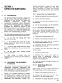
SECTION 5.
CORRECTIVE MAINTENANCE
5.2.1
5.1
-
-
-
INTRODUCTION
The Q55/Q65 Medical Treadmill is designed to
operate without scheduled maintenance. The
procedures in this section are needed for
correct ive
maintenance.
Repair
and
replacement procedures include disassembly
and reassembly procedures and are included in
Section 5.2.
Adjustment and alignment
procedures are included in Section 5.3 and
calibration procedures are included in Section
5.4. Section 5.5 is a post-maintenance test.
Refer to Section 3 for theory of operation and
Section 4 for troubleshooting procedures.
The following precautions should be observed
whenever Q55/Q65 maintenance is performed:
1.
Do not start the walking belt when
anyone is on the belt.
2.
If the treadmill shuts itself off for any
reason, remove the patient from the walking
belt immediately.
3.
To prevent high voltage electrical shock,
unplug the treadmill any time you remove the
hood.
4.
Do not wear
rotating machinery.
loose
clothing
around
5.
High voltage is present when the
treadmill hood is removed and the treadmill is
plugged in.
5.2
DISASSEMBLY AND REASSEMBLY
PROCEDURES
1.
Unplug the treadmill from the wall outlet.
2.
Re move the front handrail.
3. Remove the four bolts holding the hood to
the treadmill.
4.
Lift the hood straight up off the treadmill.
5.2.1.1
1.
Take grade to approximately 10%.
2.
Perf orm the procedure in Section 5.2.1.
3. Remove the cable ties to connector
2AIP6 and unplug connector 2AIP6.
4. Disconnect the two wires from contactor
2K 1 by removing the screws.
5. Remove the four bolts that hold the
motor in place.
6.
Remove the drive motor.
7. Replace with a new drive motor in
reverse order of disassembly.
Refer to
drawing number 0208-201 (Q55) or 0221-201
(Q65) for wire arrangement.
8. Wi th the treadmill unplugged, replace the
hood and handrail.
-
Speed Change Motor 2A2
Replacement
Speed change motor 2A2 requires replacement
if the gears break or if the motor burns out.
1.
Section 5.2.1 contains procedures to replace
components that are easily accessible under
the treadmill hood. Sections 5.2.2 and 5.2.3
contain procedures for input and output shaft
disassembly and reassembly. Section 5.2.4
Drive Motor 2M2 Replacement
Drive motor 2M2 requires replacement when
the internal thermal overload protector or
motor start switch fails or when the motor
burns out.
5.2.1.2
This section contains procedures for Q55/Q65
disassembly, component replacement and
reassembly. Because PCB components are not
field repa irable, no procedures are included
for PCB component repair or replacement.
Access Under the Treadmill Hood
Perform the procedure in Section 5.2.1.
2. Remove the cable ties from the quick
disconnect to the speed change motor.
3.
Disconnect the quick disconnect from the
5-1
black (power) lead at the motor and yellow and
gray motor leads at speed change motor
capacitor 2A2Cl.
To prevent damage to the beam chopper,
lift the tachometer bracket straight up to
remove. Ensure that the tachometer
optical sensor is securely mounted before
the treadmill is operated.
4. Remove the two bolts and washers that
hold the speed change motor to the bracket.
5.
Remove the speed change motor.
6. Replace the speed change motor in
reverse order of disassembly.
Refer to
drawing number 0208-201 (Q55) or 0221-201
(Q65) for wire arrangement.
3. Remove the two screws on top of the
tachometer optical sensor and lift the
tachometer bracket straight up.
7. Restore power to the treadmill
calibrate speed (Section 5.4. I).
4. Remove the two screws and spacers that
hold the small circuit board in place.
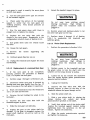
5.2.1.3
and
Speed Change Motor CapaCitor
2A2C1 Replacement
Failure of the speed change motor capacitor
2A2Cl can cause the speed change motor to
run sluggishly, blow a fuse (2AIF5 or 2AIF6)
or prevent the motor from starting. A 4
microfarad capacitor is used on all 60 Hz
models of the Q55/Q65 treadmill, and a 6
microfarad capacitor is used on all 50 Hz
models of the Q55 treadmill.
1.
6. Replace the wires to the tachometer
assembly. Refer to drawing number 0208-201
(Q55) or 0221-201 (Q65) for wire arrangement.
7. Align the tachometer beam
(Section 5.3.5) and reconnect 2AIP7.
5.2.1.5
Perform the procedure in Section 5.2.1.
2. Note the color and arrangement of the
four wires to the capacitor.
3. Loosen the bolts holding the capacitor
bracket in place.
4. Pull the capacitor straight up out of the
bracket.
5. Replace
with
a
new
capacitor,
reassembling in reverse order of disassembly.
Refer to drawing number 0208-201 (Q5S) or
0221-201 (Q6S) for wire arrangement.
6.
5. Replace the two screws and spacers on
the new small circuit board and the two
screws on the new tachometer optical sensor.
Tighten the capacitor in the bracket.
7. With the treadmill unplugged, replace the
hood and handrail.
1.
1.
Tachometer 2A3 Optical Sensor
Replacement
Perform the procedure in Section 5.2.1.
2. Remove the cable ties to connector
2AIP7 and unplug connector 2AIP7.
5-2
Tachometer Beam Chopper
Replacement
Perform the procedure in Section 5.2.1.
2. Remove the two bolts that hold the
tachometer optical sensor in place. Move the
tachometer optical sensor out of the way.
3. Remove the beam chopper by removing
the bolt and chopper wheel from the end of
the output shaft.
4.
Replace with a new beam chopper.
S. Replace the tachometer optical sensor on
the bearing cap.
6. Align the
(Section 5.3.5).
5.2.1.6
5.2.1.4
chopper
tachometer
beam
chopper
Grade Motor 2M1 and/or Grade Motor
Gearbox Replacement
1. Block the treadmill headframe securely to
ensure that the treadmill will not drop when
the grade motor or grade chain is removed.
2.
Perform the procedure in Section S.2!1.
3. Remove the cable ties between 2AIP3
and the grade motor connector box.
4. Unplug all connections
including 2AIPll.
to
the
Refer to drawing number 0208-201 (Q55) or
221-201 (Q65) for wire arrangement.
PCB,
WARNING
5. Remove the eight bolts holding the PCB
to the PCB bracket.
-
-
6. Remove the four bolts holding the PCB
bracket to the grade motor connector box.
Do not wear loose clothing around
rotating machinery.
Hi gh voltage is
present when the treadmill cable is
plugged in.
7. If you are replacing the motor but not the
gearbox, remove the four bolts holding the
motor to the gearbox and lift the motor
straight up.
12. Restore power to the treadmill and test
the operation of the new grade motor.
8. If you are replacing only the gearbox or
the motor and the gearbox, remove the four
bolts holding the gearbox onto the headframe
and lift the motor and gearbox straight up.
The gearbox can then be removed from the
motor by unbolting the four bolts.
-
5.2.1.7
1.
Replace the bolts removed in steps 5 and
6.
c.
Replace all connections to the PCB.
d.
Proceed to step 11.
c.
d.
Replace the four bolts
gearbox to the headframe.
holdling
Perform the procedure in Section 5.2.1.
I
Do not wear loose clothing around
rotating machinery. High voltage is
present when the treadmill cable is
plugged in.
2. With the hood removed, restore power to
the treadmill and turn the grade motor on
until the nylon setscrew on the sprocket is
accessible.
10. If replacing the gearbox or the motor and
the gearbox, perform the following.
a.
Grade Potentiometer 2R1
Replacement
WARNING
Replace the four bolts holding the motor
to the gearbox, tightening the bolts
evenly.
b.
b.
-
13. Recalibrate grade (Section 5.4.2).
9. If replacing only the motor, perform the
following:
a.
-
I
3.
Unplug the treadmill.
4.
Release the nylon setscrew.
the
Replace the grade chain and inspect the
tension on the grade chain. If there is
more than approximately l/8-inch play in
the grade chain, loosen the four bolts
holding the gearbox to the headframe and
move the grade motor to correct the
position of the chain. Tighten the four
bolts when correct tension is achieved.
Replace the bolts removed in steps 5 and
6.
5. Hand turn the grade potentiometer 2Rl
until the steel setscrew on the sprocket is
visible.
6.
Remove the steel setscrew.
7. Push the whole sprocket and chain
assembly away from the grade potentiometer.
8. Remove the 1/2-inch brass nut and cable
tie and the whole potentiometer will come off.
9. Note the color and arrangement of wires
to the potentiometer.
Replace all connections to the PCB.
11. Replace the wires to the grade motor.
10. Unsolder the three wires (black, brown
and red) to the potentiometer.
5-3
11. Replaee with a new potentiometer and
reassemble in reverse order of disassembly.
Refer to drawing number 0208-201 (Q55) or
0221-201 (Q65) for wire arrangement.
12. When the grade potentiometer, the wires
and the setscrews are in place, calibrate the
grade potentiometer using the procedure in
Section 5.4.4.
13. Calibrate grade (Section 5.4.2).
5.2.1.8
1.
Perform the procedure in Section 5.2.1.
the
6. Unplug the treadmill and replace the hood
and handrail.
5.2.2
Disassembly to Remove the Input
Shaft Assembly
1. With the treadmill on, decrease speed to
minimum.
Printed Circuit Board (PCB) 2A1
Replacement
2. Unplug all connectors
including 2Al PI 1.
5. Restore power to the treadmill and test
the operation of the new drive motor
contactor.
the
2. Unplug the treadmill,
remove the
handrail, and lift the hood straight up off the
treadmill.
PCB,
3. Push the wire assemblies behind the PCB
bracket.
Exercise caution to avoid damage to
bearings and caps on the input shaft. If
the input shaft is scarred or if the
moveable sheave is frozen on the input
shaft, the entire shaft assembly must be
replaced.
4. Remove the eight bolts that hold the PCB
to the PCB bracket.
5. Replace with a new PCB and reassemble
in reverse order of disassembly. Refer to
drawing number 0208-201 (Q55) or 0221-201
(Q65) for wire arrangement.
NOTE
A replacement input shaft assembly can
be obtained from
Quinton Medical
Company's Service Department.
6. Recalibrate speed (Section 5.4.1), grade
the
trip
level
(Section
5.4.2)
and
potentiometer (Section 5.4.3).
Perform the procedure in Section 5.2.1.
3. Take a rope or flexible belt and put it
around the variable speed belt. Pull straight
up to loosen the belt. Figure 5-1 illustrates
the loosening of the variable speed belt.
2. Note the color and arrangement of wires
to contactor 2Kl.
4. Remove the V-belts from the machined
pulley.
3. Remove the wires to the contactor,
including two wires to the motor, two wires to
the power supply, two wires to 2AIP10, and
three wires to 2AIP2.
5. With an air wrench or a ratchet wrench
with a long extension, remove the four bolts
that hold the bearing caps in place. Set the
fan aside.
4. Replace with a new contactor and
reconnect the wires. Refer to drawing number
0208-201 (Q55) or 0221-201 (Q65) for wire
arrangement.
6. Lift the whole assembly straight up and
forward, avoiding damage to the speed change
motor, output shaft, or walking belt. Note
that the bearing caps are upside-up if the
narrow side is down.
5.2.1.9
1.
Drive Motor Contactor 2K1
Replacement
WARNING
I
Do not wear loose clothing around
rotating machinery. High voltage is
present when the treadmill cable is
plugged in.
5-4
5.2.2.1
1.
Input Shaft Assembly Replacement
Perform the procedure in Section 5.2.2.
-
WARNING
I
'".Js
Do not wear loose clothing around
Hi gh vol tage . ,is
rotating machinery.
present when the treadmill cable is
plugged in.
-
11. Restore power to the treadmill and test
the operation of the new input shaft. Verify
that the treadmill operates through the full
range of speeds.
12. Unplug the treadmill and replace the hood
and handrail.
13. If using the Q2000 or the 645 PTC,
perform treadmill calibration (Steps 1, 2 and 7
of Section 4.4 of the Q2000 Service Manual or
Section 6.2 of the 645 PTe Technical Manua!).
5.2.2.2
Figure 5-1
Replacement of a Seized Bearing on
the Input Shaft
NOTE
Loosening the Variable Speed Belt
Replacement of a loose or seized
throw-out
bearing
requires
special
equipment and should be performed at the
factory.
2.
Remove the machined pulley and key.
1.
3. Align the speed change spindle assembly
with the pin on the base of the headframe.
4. Replace the machined pulley on the shaft
with the key in place.
5. Replace the bearing caps, narrow side
down, and place the bolts in the holes without
tightening them.
6.
2. Inspect the shaft for damage. If the shaft
is damaged, obtain a replacement input shaft
assembly and replace the shaft using the
procedure in Section 5.2.2.1.
3. If you are replacing a bearing on the left
end of the shaft, remove the machined pulley
and key. Remove the left bearing cap using a
gear puller or press.
Install an undamaged input shaft assembly.
7. Pry open the output pulley slightly. Pull
on the variable speed belt at the output end to
snap the belt into place.
8. Tighten the bolts, installing the fan on the
center bearing cap.
-
Perform the procedure in Section 5.2.2.
9. Snap the V4)elts on and align the
machined pulley with the pulley on the drive
motor shaft.
Use the setscrew on the
machined pulley to make the adjustment.
10. Check the alignment of the input shaft.
The variable speed bel t should be parallel to
the side of the headframe.
4. If you are replacing a bearing on the right
end of the shaft, remove the bearing cap using
a gear puller or press.
5. Remove the bearing using a gear puller or
press. Refer to Step 2 if the input shaft is
damaged.
6. Press a new bearing onto the shaft using
an arbor press.
7. Apply Loctite Primer T and Loctite RC
609 to the inside of the bearing cap and
replace the bearing cap.
8.
Replace the machined pulley and key if
5-5
they were removed. Align the machined
pulley with the drive motor shaft using the
setscrew on the pulley to align.
5. Replace with an undamaged speed change
spindle assembly and align with the pin at the
base of the head frame.
9. Replace the input shaft by performing
steps 3 through 13 of Section 5.2.2.1.
.
6.
5.2.2.3
7. Perform steps 3 through 13 of Section
5.2.2.1 to replace the input shaft.
Reinstallation of a Loose Bearing on
the Input Shaft
Replace the chain on the spindle sprocket.
8.
Calibrate speed (Section 5.4.1).
NOTE
Replacement of a loose or seized
throw-out
bearing
requires
special
equipment and should be performed at the
factory.
I.
Perform the procedure in Section 5.2.2.
2. Carefully remove the loose bearing from ."
the end of the shaft.
.
.
.•
,., .'.C
3. Inspect the input shaft. If the shaft is
damaged, obtain a replacement input shaft
assembly and replace the shaft using the
procedure in Section 5.2.2.1.
4. If the shaft is not damaged, perform the
following.
a.
Clean the inside of the bearing cap and
the inner and outer bearing races with
Loctite Primer T.
"
5.2.2.5
V-Belt and/or Machined Pulley
Replacement
I. Inspect the V-belt and the machined
pulley to determine if the pulley has worn
unevenly because of a glazed V-belt.
2. If replacing a V-belt or if replacing the
machined pulley on a Q55, perform the
procedure in Section 5.2.1.
3. If replacing the machined pulley on a Q65,
perform the procedure in Section 5.2.2 to
remove the input shaft.
4. Loosen the setscrew on the machined
pulley. The V-belts can be removed by
applying side' pressure to the belts while
rotating the pulley.
b.
Apply Lo.ctite RC 609 to the end of the"
shaft, the inside of the bearing cap and'
the inner and outer races of the bearing.
5. Ir replacing the machined pulley, remove
the 'pulley and key from the shaft. On the Q55
treadmill it may be necessary to remove the
cable ties to move the cable assembly ou~ of
the way.
c.
Assemble the bearing and the bearing cap .
and allow approximately 30 minutes for"
the Loctite RC 609 to set.
6. .' If replacing a V-belt or the. machined
on the Q55, reassemble in reverse order
of disassembly.
5. Perform steps 3 through 13 of' Section
5.2.2.1 to install the input shaft.
7. , If replacing the machined pulley on a Q65,
perform steps 3 through 13 of Section 5.2.2.1
to reassemble the input shaft.
5.2.2.4
1.
Speed Change Spindie Assembly
Replacement
~~}
Perform the procedure in Section 5.2.2.
2. Pull the speed change spindle asserribl'y
towards the drive motor.
o·
3. Remove
sprocket.
the
chain
p~ley
from
'.:"
8. Align the machined pulley to the pulley on
the output shaft of the drive motor. Use the
se~,screw on the machined pulley to make the
adjustment.
9."
Replace the hood and handrail.
".
~i~assembly to Remove the Output
Shaft Assembly
5.'2:3
.. , " f '
4. Remove the speed change
s[>lp~~~~
assembly from the pin at the base of the
headframe.
5-6
+'l.c,
:
1.;~1 ~ith the t..readmill on, decrease speed to .
minimum.
2. Unplug the treadmill, remove the handrail
R.nd lift the hood straight up off the treadmill.
6. Install the tachometer beam chopper and
perform the alignment in Section 5.3.5.
7. Unplug the treadmill and replace the hood
and handrail.
Exercise caution to avoid damage to
bearings and caps on the output shaft. If
the output shaft is scarred or if the
moveable sheave is frozen on the output
shaft, the entire shaft assembly must be
replaced.
NOTE
8. Restore power to the treadmill and
calibrate speed (Section 5.4.1).
Before
returning the treadmill to service, ensure that
the treadmill calibration has been performed
on the Q2000 (Steps 1, 2 and 7 of Section 4.4
of the Q2000 Service Manual) or the 645 PTC
(Section 6.2 of the 645 PTC Technical Manual).
5.2.3.2
A replacement output shaft assembly can
be obtained from Quinton
Company's Service Department.
Replacement of a Seized Bearing on
the Output Shaft
Medical
3. Carefully remove the tachometer optical
sensor from the bearing cap.
1.
Perform the procedure in Section 5.2.3.
Remove the tachometer beam chopper.
2. Inspect the shaft for damage. If the shaft
is damaged, obtain a replacement output shaft
and replace the shaft using the procedure in
Section 5.2.3.1.
5. Remove the speed change motor by
removing the two bolts holding it to the
bracket.
3. Remove the bearing cap from the end of
the shaft using a gear puller or press. Refer
to Step 2 if the output shaft is damaged.
6. With an air wrench or a ratchet wrench
with a long extension, remove the four bolts
holding the beari ng caps in place.
4. Remove the old bearing from the shaft
using a gear puller or press.
4.
7. Take a rope or flexible belt and put it
around the variable speed belt. Pull straight
up to loosen the belt. Figure 5-1 illustrates
the loosening of the variable speed belt.
8.
5. Press the new bearing onto the shafft
using an arbor press.
6. Apply Loctite Primer T and Loctite RC
609 to the inside of the beari ng cap and
replace the bearing cap.
Remove the output shaft assembly.
7. Replace the output shaft by performing
steps 2 through 8 of Section 5.2.3.1.
5.2.3.1
Output Shaft Assembly Replacement
1.
Perform the procedure in Section 5.2.3.
2.
Slip the variable speed belt onto the input
and ou tput pulleys.
3. Install an undamaged output shaft by
replacing the bearing caps, narrow side down,
and tightening the bolts with an air wrench or
a ratchet wrench with a long extension.
5.2.3.3 Reinstallation of a Loose Bearing on
the Output Shaft
1.
Perform the procedure in Section 5.2.3.
2. Carefully remove the loose bearing from
the end of the shaft.
4. Install the speed change motor back onto
the speed change motor bracket.
3. Inspect the output shaft. If the shaft is
damaged, obtain a replacement output shaft
assembly and replace the shaft using the
procedure in Section 5.2.3.1.
5. Replace the tachometer optical sensor on
the top of the bearing cap.
4. If the shaft is not damaged, perform the
following.
5·7
a.
Clean the inside of the bearing cap and
the inner and outer bearing races with
Loctite Primer T.
2. 1Dnplug the treadmill, remove the handrail
and hood, and lift the hood straight up off the
treadmill.
b.
Apply Loctite RC 609 to the end of the
shaft, the inside of the bearing cap and
the inner and outer races of the beari ng.
3. Block the front of the headframe with 3to 6-inch wooden blocks to take the weight off
the treadmill wheels.
c.
Assemble the bearing and the bearing cap
and allow approximately 30 minutes for
the Loctite RC 609 to set.
4. If the rack gear is completely jammed,
proceed to Section 5.2.4.2.
5. Perform steps 2 through 8 of Section
5.2.3.1 to install the output shaft assembly.
5.2.3.4
WARNING
Variable Speed Belt Replacement
Do not wear loose clothing around
rotating machinery.
High voltage is
present when the treadmill cable is
plugged in.
I.
Perform the procedure in Section 5.2.2 to
remove the input shaft assembly.
2. Perform the procedure in Section 5.2.3 to
remove the output shaft assembly.
3. Perform the procedure in Section 5.2.3.1
to replace the output shaft assembly.
3. Perform the procedure in Section 5.2.2.1
to replace the input shaft assembly.
5.2.3.5
I.
Timing Belt Replacement
Perform the procedure in Section 5.2.3.
2. Take the molding and side channels off
both sides of the treadmill. Use a 1/2-inch
wrench to remove the five bolts on the
treadmill deck and a 9/16-inch wrench to
remove the two bolts holding the side channel
to the headframe.
I
5. Restore ;power to the treadmill and raise
the wheels approximately 1/2 inch off the
floor by decreasing grade.
6. Remove the two hexbolts holding the
wheels to the rack gears.
Note the
arrangement of the washers used as spacers.
7. Decrease grade until the rack gears start
bouncing on the pinion shaft.
8.
Unplug the treadmill.
9.
Lift the rack gears straight out the top.
5.2.4.1
Rack Gear Reassembly
1.
If a rack gear is completely jammed,
perform the procedure in Section 5.2.4.2,
omitting step I of Section 5.2.4.2.
Perform the procedure in Section 5.2.4.
3.
Slide the timing belt off.
2.
4.
Replace with a new timing belt.
3. Install
the
undamaged
rack gears
simultaneously so that they will be parallel.
5. Reinstall the output shaft by performing
steps 2 through 8 of Section 5.2.3.1.
6.
Reinstall the side channels and molding.
7. Adjust the timing belt tension (Section
5.3.1).
5.2.4
Disassembly to Remove the Rack Gears
or Pinion Shaft
1. If treadmill grade will change at all, take
the grade to approximately 12 % (6-7 0 ).
5-8
WARNING
I
,Do not wear loose clothing around
rotating machinery.
High voltage is
present when the treadmill cable is
plugged in.
4. Restore power to the treadmill and
decrease grade. After the gears bounce a few
times, increase grade. This should cause the
rack gears to mesh in exactly the same place
on both rack gears.
9.
Rebolt the handrail support in place.
5. Run the rack gears down past the bottom
of the handrail support.
-
.-
WARNING
6. Check under the bottom of the handrail
support to verify tha t the rack gears are
meshing properly. They should protrude an
equal amount.
I
Do not wear loose clothing around
High voltage is
rotating machinery.
present when the treadmill cable is
plugged in.
7. RUn the rack gears down until there is
enough room to replace the wheels.
10. Restore power and decrease grade to run
the other rack gear out the top.
8. Replace the two bolts that hold the
wheels to the rack gears. Reassemble in the
configuration noted at step 6 of Section 5.2.4.
11. Perform steps 3 through 13 of Section
5.2.4.1 to reassemble the treadmill and
calibrate grade•
9. Run grade down until the wheels touch
the floor.
5.2.4.3
10. Grease the rack gears.
1.
11. Remove
headframe.
the
blocks
supporting
Pinion Shaft Replacement
Perform the procedure in Section 5.2.4.
the
WARNING
12. Calibrate grade (Section 5.4.2.).
Do not wear loose clothing around
rotating machinery.
High voltage is
present when the treadmill cable is
plugged in.
13. Unplug the treadmill and replace the hood
and handrail.
5.2.4.2
Replacement of a Jammed Rack Gear
1. If the rack gear is not completely
jammed, perform the procedure in Section
5.2.4.1 to replace the rack gear.
2.
Perform steps 1 through 3 of Section 5.2.4.
3. Determine which rack gear is jammed by
shaking each rack gear lightly from the top. If
there is no play in the rack gear, it is jammed.
4. Block the treadmill so that the wheels are
1/2 to 1/4 inch off the floor.
5. Remove the bolt holding the wheel to the
rack gear.
6. Remove the four bolts that hold the
handrail support in place.
7.
Slide the rack gear out sideways.
8. Inspect the gear on the pinion shaft for
damage. If the gear is damaged, replace the
pinion shaft (Section 5.2.4.3) as well as the
rack gear.
I
2. Restore power to the treadmill and use
the grade motor to turn the shaft until the
setscrew on the torque limiter is visible.
3. Loosen but do not remove the setscrews
from the torque limiter, grade potentiometer
sprocket and set collars.
4.
Unplug the treadmill.
5. Remove the four bolts that hold the
handrail support in place on the side of the
treadmill nearest the speed change motor.
6.
Slide the pinion shaft out.
7. Slide a new pinion shaft in, placing the
torque limiter, set collars and grade
potentiometer sprocket on the shaft.
8. Verify that neither end of the pinion shaft
touches the handrail support bracket before
tightening down the setscrews on the set
collars. Tighten the setscrews.
9. Align the grade potentiometer sprocket
and tighten the setscrew.
5-9
10. Align the torque limiter and grade motor
sprocket using the setscrew on the grade
motor sprocket.
11. Perform steps 3 through 13 of Section
5.2.4.1 to replace the rack gears and
recalibrate grade.
5.2.5
Belt Tracking Switch Replacement
4. Carefully place the whole treadmill on its
right side on blocks.
5. Release the quick disconnects on the
wires leading to the belt tracking swi tches.
5.2.6.1
Walking Belt Replacement
1.
Perform the procedure in Section 5.2.6.
If a belt tracking switch is defective, replace
it with a Quinton PIN 06872-001 microswitch
and a PIN 02702-001 quick disconnect female
terminal.
2.
Slide the walking belt off.
3.
Slide a new walking belt on.
1. Increase grade to maximum and unplug
the treabmill.
4. Re~onnect the quick dis~onne.cts on the
wires to the belt tracking sWItches.
2. Note the color and arrangement of wires
to the switch and release the quick
disconnects at the switch.
5. Return
position.
3. Remove the two bolts and nuts holding
the switch in place.
4. Replace with a new switch and terminal
and rebolt onto the bracket.
5.
Reconnect the wires.
6. Adjust the lever arms so that there is 1/2
to 3/4 inch distance between the lever arm
and the walking belt when the walking belt is
centered.
7. Restore power to the treadmill and verify
that a belt tracking error message is displayed
on the treadmill controller when the switch is
manually actuated.
5.2.6
2. Pry the molding off both sides of the
treadmill. Use a 1/2-inch wrench to remove
the five bolts on the treadmill deck and a
9/16-inch wrench to remove the two bolts
holdi ng the side channels on both sides of the
headframe.
3. Block the right side of the headframe and
deck to prevent damage to the right side
channel.
treadmill
to
an
upright
Replace the side channels and moldings.
7. With the treadmill unplugged, replace the
hood and handrail.
8. Restore power to the treadmill and adjust
the walking belt tension by performing the
procedure in Section 3.2.1 of the Q 55/Q65
Operator Manual.
9.
Calibrate speed (Section 5.4.1).
5.2.6.2
Drive or Idler Pulley Replacement
NOTE
Repair of seized or loose bearings or a
damaged drive or idler pulley requires
special equipment and should be done at
the factory.
Disassembly to Remove the Walking
Belt or Drive or Idler Pulley
1. Unplug the treadmill, remove the handrail
and hood and lift the hood straight up off the
treadmill.
5-10
6.
the
1.
Perform the procedure in Section 5.2.6.
2. Remove the drive or idler pulley. The
timing sprocket on the drive pulley comes off
easily when the drive pulley is free.
3. Replace the drive or idler pulley with new
or repaired assembly.
4. Perform steps 4 through 9 of Section
5.2.6.1 to reassemble.
5.2.6.3
Removing a Burr from the Deck
....
5.3.3
The deck surface has been anodized. Do
not machine the deck as this will alter the
protect ive coating.
1. Perform the procedure in Section 5.2.6 to
disassemble the walking belt.
2.
Slide the walking belt off.
3.
File only the burr off the deck.
Adjusting the Setscrews on the Speed
Change Yoke
1. Verify that step 7 of the speed calibration
procedure (Section 5.4.1) has been performed
and that the speed change yoke setscrews
require adjustment.
2. Unplug the treadmill, remove the handrail
and hood, and lift the hood straight up off the
treadmill. Locate the speed change spindle
assembly (Figure 5-2).
4. Perform steps 4 through 9 of Section
5.2.6.1 to replace the walking belt and
reassemble the treadmill.
5.3
-
ADJUSTMENT AND ALIGNMENT
PROCEDURES
Adjustment procedures are included in this
section to adjust the treadmill for proper
operation. Alignments of chains and .be~ts,
wi th the exception of the self-abgnIng
variable speed belt, can be done using the
setscrews provided and a straightedge.
5.3.1
-
Timing Belt Tension Adjustment
1. Pry the molding loose from both side of
the treadmill.
2. Remove the four 9/16-inch bolts and
washers on either side of the headframe.
Figure 5-2
3. If speed will not decrease to minimum,
perform the following.
3. If the timing belt is so tight that it hums
or whines during operation, move the
headframe assembly toward the walking belt.
WARNING
4. If the timing belt is so loose that it slips
on the timing pulley, move the headframe
further away from the walking belt.
-
5.
Replace the bolts and washers.
6.
Replace the molding.
5.3.2
I
Do not wear loose clothi ng around
rotating machinery.
High voltage is
present when the treadmill cable is
plugged in.
a.
Restore power to the treadmill and
the speed
change spindle
observe
assembly and the speed indicator as you
decrease speed to minimum. Unplug the
treadmilL
b.
Work from the front end of the treadmill
to adjust the speed change yoke
setscrew. Use a liS-inch Allen head
wrench to turn the setscrew nearest the
beari ng cap one turn counterclockwise.
Walking Belt Tension or Track
Adjustment
Adjust the walking belt tension by performing
the procedure in Section 3.2.1 of the Q55/Q65
Operator Manual. Adjust the walking belt
track by performing the procedure in Section
3.2.2 of the Q55/Q65 Operator Manual.
Speed Change Spindle Assembly
5-11
c.
Repeat steps 3a and 3b as needed to
achieve minimum speed.
4. If speed will not increase to maximum,
perform the following.
WARNING
I
Do not wear loose clothing around
rotating machinery. High voltage is
present when the treadmill cable is
plugged in.
a.
b.
c.
Restore power to the treadmill and
observe
the
speed change
spindle
assembly and the speed indicator as you
increase speed to maximum.
Work from the walking belt end of the
headframe to adjust the speed change
yoke setscrew. Use a lI8-inch Allen
wrench to turn the setscrew nearest the
moveable
sheave
one
turn
counterclockwise.
Repeat steps 4a and 4b as needed to
achieve maximum speed.
4. Using an amp probe capable of measuring
low amperage accurately, perform the
following procedure to reset the torque limiter.
a.
PI ace the amp probe around a single red
or black lead to connector 2AIP3.
Measure the current draw when the
torque limiter is actually slipping.
b.
Compare the measured amperage with the
amperage noted on the grade motor
nameplate.
c.
If measured amperage is higher than rated
amperage, within 5%, slacken the torque
limiter
nut
(turn
the
nut
counterclockwise) with water pump pliers
until the amperage reading is correct.
d.
If measure amperage is lower than rated
~mperage, within 5%, tighten the torque
IImlter nut (turn the nut clockwise) until
the a mperage reading is correct.
5. If an amp probe capable of measuring low
amperage accurately is not available, the
following method may also be used to reset
the torque limiter.
a.
Place weights (400 lb.) about 18 inches
from the front edge of the deck in the
approximate position a patient's front
foot would strike the treadmill.
b.
Tighten the torque limiter nut (turn the
n~t clockwise) until the treadmill just
pIcks up the weight. Stop tightening the
nut as soon as the treadmill picks up the
weight.
5. With the treadmill unplugged, replace the
hood and handrail.
6. Perform treadmill calibration on the
Q2000 (Steps 1, 2 and 7 of Section 4.4 of
Q2000 Service Manual) or 645 PTC (Section
6.2 of PTC Technical Manual).
5.3.4
Torque Limiter Adjustment
1. Unplug the treadmill and remove the
handrail and hood.
6. Tighten down the tabs on the torque
limiter.
2. Use a fla t-bladed screwdriver to loosen
the tabs on the torque limiter.
7. Unplug the treadmill and replace the hood
and handrail.
WARNING
I
Do not wear loose clothing around
Hi gh vol tage is
rotating machinery.
present when the treadmill cable is
plugged in.
3. Restore power to the treadmill and
decrease grade to minimum. Keep the grade
decrease pushbutton continuously depressed
while performing step 4 or 5.
5-12
8. Restore power to the treadmill and
perform treadmill calibration of the Q2000
(Steps 1, 2 and 7 of Section 4.4 of Q2000
Service Manual) or 645 PTC (Section 6.2 of
645 PTC Technical Manual).
5.3.5
Tachometer Beam Chopper Alignment
1. Unplug the treadmill and remove the
handrail and hood.
2. Center the beam chopper by sliding it
along the shaft and checking the relationship
to the tachometer U;:D.
/\ screwdriver may
c.
be used to slide the beam (~hopp(~r !1.long the
shaft. The bea m .::-hoppel' should be at the
exact center of tile gnp.
3.
Calibrate speed
5.4
CALIBRATION PROCFJI. mES
The calibration pro(!C'dnrl ':;:: included in this
section should be performed 98 needed to ke(~jJ
treadmill
speerl
and
indications
accurate.
The
calibration
procedures included In
Q2000 Service
Manual (Steps 1, :~ 811(; 7 of Se,~tion 4.4) and
the 645 PTC Technienl i\1,;nuaI (Seetion 6.2)
compute coasting con:;;'f\r;ts and speed Hnd
grade ranges.
They :h; not affect the
performance of the il'end.mill. After any
speed or grade calitwation hns been performed,
the Q2000 or 64!) PTe: tn::fH:lmill calibration
should also be performed to ensure that
coasting' constants and
nnd grade ranges
are correct.
5.4.1
Speed Calibratkm
hand-held digitnl taehometer (Biddle
or equiw\lenO f'lid H multi meter
(Fluke
#8022B
ot'
equivalent)
are
recommended for speed caHhl'lltion. Though
the procedure can be performed without using
either instrument~ the ,'csuHing calibration
will be less accura.h~. The followinr~ proeedure
ean be perfol'med with tll>' hood and handrail
re moved, provided Cllll tion lS i:-;X f~rcised.
4. If the treadmill speed reading stayed at
zero ...... hile step 1 or 2 was being performed,
troubleshoot the tachometer (Section 4,
Troubleshooting Tree L).
5. If the speed reacting was not accurate on
the Q200n or 645 PTC, perform the following.
a.
ore tdnr-: ;1 hand-Ileld digital
take the
I() approximately r{
m ph/l 1.3 kph and m c.'l::mrp th(~ speed of the
walking belt (1 mph :- 88 rpm).
If
you
2. If you are not
n digHal tachometer,
take the sreed to I mph/l
kph and measure
speed by performing stC[,B 2 through 4 of
Section 3.2.3 of the Q55/q65 Operator Manual.
quinton!s Treadmill
3. If you are usi
Controller, turn off til" tr(mdmill and see if
the speed reading goes to z;:~ro. If it do(~s not,
perform the following:,
a.
Remove the four boits holding the control
panel on the Trr:adrnill Controller.
b.
Turn the adjustmr:FI :o;crew located on the
back of the spet;d meter' until the speed
meter reading is zp,·o.
and
WARNING
Do
remove
the
I
not
wear loose clothing around
machinery.
High voltage is
present when the treadmill cable is
plugged in.
rotating
b.
Restore power to the treadmilL Turn the
screw at tachometer gain potentiometer
2AIRl3 on the PCB until the speed
reading is correct. If you are using a
multimeter, 1 milliampere should equal 1
m phil. 6 kph.
#~l59970
1.
If the hood and handrail are still in place,
unplug the treadmill
handrail and hooct.
A
tachometer~
Replace the four holts to reassemble the
Tl"tH:tdmiU Controller.
c.
Unplug the treadmill and replace the hood
and handraU. Proceed to step 7.
6. If the speE!d reading was not accurate on
Quinton's Treadmill Controllel', use the
adjustment screw to the left of the DEC
pushbutton to adjust the speed meter.
7. Take speed to maximum and minimum to
verify that the treadmill operates through the
full range of speeds (Q55 should go from 1
mph/l.6 l<ph to 10 mph/16 kph and Q65 should
go from 1.5 mph/2.4 kph to 15 mph/24 kph).
8. If the speed will not increase to maximum
or de:crel1se to minimum, adjust the setscrew
on the speed change yoke (Section 5.3.3).
9. Befm'e returning the treadmill to service,
unplug the treadmill and replace the hood and
handrail.
10. Perform the treadmill calibration on the
Q2000 (Steps 1, 2 and 7 of Section 4.4 of the
Q2000 Service Manual) or the 645 PTC
(Seetion 6.2 of the 645 PTe Technical Manual).
5-13
5.4.2
Grade Calibration
b.
A multimeter (Fluke #8022B or equivalent)
and a universal protractor level (Sears
Craftsman #9 3995 or equivalent) are
recommended for grade calibration. Though
the procedure can be performed without using
ei ther instrument, the resulting calibration
will be less accurate. The following procedure
can be performed with the hood and handrail
removed, provided caution is exercised.
1. Take porade to minimum. Use a bubble
level or a protractor to verify that the
treadmill is at zero grade.
NOTE
Restore power to the treadmill and turn
the
screw
at
the
grade
zero
potentiometer 2AIR29 on the PCB until
the grade indication is zero. If you are
using a multi meter, the reading at
2AIR29 should be zero milliamperes.
5. If you are using a protractor to measure
grade, measure grade and proceed to step 8.
6. Mark a spot on the floor exactly 4 feet in
front of the treadmill deck foot.
7. Increase the treadmill grade to 25% (14°)
and, using a carpenter's square, measure the
height from the spot marked on the floor. The
height should be 1 foot.
Grade readings are relative to the floor.
A significantly slanted floor will affect
grade measure mente
8. If the height from the floor is not 1 foot
or angle is not 14°, manipulate the grade so
that the height and angle are correct
2. Use the bubble level or protractor to
verify that the floor is level. Move the
treadmill to a level area if necessary to
calibrate grade.
9. If you are using Quinton's Treadmill
Controller, adjust the grade meter to exactly
25% using the adjustment screw directly to
the right of the ELEV UP pushbutton.
3. If you are using Quinton's Treadmill
Controller, unplug the treadmill and see if the
grade meter goes to zero. If it does not,
perform the following.
10. If the grade indication is not correct on
the Q2000 or 645 PTC, perform the following.
a.
Remove the four bolts holding the control
panel in place.
b.
Turn the adjustment screw located on the
back of the grade meter until the grade
meter reading is zero.
c.
Replace the four bolts to reassemble the
Treadmill Controller.
4. If the bubble level indicates grade is zero
but the grade reading is not zero, perform the
following.
a.
If the hood and handrail are still in place,
unplug the treadmill and remove the
handrail and hood.
I WARNING
I
Do not wear loose clothi ng around
rotating machinery.
High voltage is
present when the treadmill cable is
plugged in.
5·14
a.
If the handrail and hood are still in place,
unplug the treadmill and remove the
handrail and hood.
WARNING
I
Do not wear loose clothing around
rotating machinery.
High voltage is
present when the treadmill cable is
plugged in.
b.
Restore power to the treadmill and turn
the screw at the grade potentiometer
2AIR30 on the PCB until the grade
readi ng is 25% • If you are using a
multi meter, the reading should be 12.5
milliamperes (I millilampere should equal
a 2% increase in grade).
11. Before returning the treadmill to service,
unplug the treadmill and replace the hood and
handrail.
12. Perform the treadmill calibration on the
Q2000 (Steps 1, 2 and 7 of Section 4.4 of the
Q2000 Service Manual) or 645 PTC (Section
6.2 of the 645 PTC Technical ManuaI).
5.4.3
Trip Level (Low Volts) Calibration
This procedure is included to provide
information about the setting of trip level
potentiometer 2AIR23. This potentiometer
should not require resetting once it has been
set at the factory.
1. Unplug the treadmill and remove the
handrail and hood.
2. Hook the treadmill up to a Variac
autotransformer that can provide at least 10%
less than operating voltage (for 230V, use
207V; for 208V, use 187Vj for 115V, use 103V).
WARNING
1. Take treadmill grade to approximately
12% (6-7 0 ).
2. Unplug the treadmill, remove the handrail and lift the hood straight up off the
treadmill.
3. Turn the sprocket on the pinIOn shaft
toward the drive motor until the grade reading
is 8-10% (5-6 0 ).
WARNING
I
Do not wear loose clothing around
rotating machinery.
High voltage is
present when the treadmill cable is
plugged in.
3. Turn the drive motor on at 1-3 mph or 2-5
kph.
4. Turn
the
screw
at
trip
level
potentiometer 2AIR23 on the PCB so that the
LO VOLTS LED on the PCB just barely comes
on.
5. Unplug the treadmill from the Variac
autotransformer and replace the handrail and
hood.
5.4.4
hood and handrail already re moved and power
on, provided caution is exercised.
Grade Potentiometer Calibration
This procedure may be performed wi th the
I
Do not wear loose clothing around
rotating machinery.
High voltage is
present when the treadmill cable is
plugged in.
4. Restore power to the treadmill and
decrease the grade to minimum. Verify that
the torque limiter is slipping and that the
grade is level. The grade potentiometer is
now set at zero.
5.
5.5
Calibrate grade (Section 5.4.2).
POST·MAINTENANCE PROCEDURE
The checkout procedure provided in Section
2.4 can be performed to verify that the
Q55/Q65 treadmill is operable following
maintenance. If a more detailed procedure is
desired, the troubleshooting tree provided on
pages 4-2 through 4-5 can be used to perform
a checkout test.
5-15
SECTION 6. DRAWINGS
-
This section contains the assembly drawings and schematics for the Q55/Q65 Medical
Treadmill. The following drawings are provided in the order listed:
DRAWING NUMBER
TITLE
NO. OF SHEETS
00208-001 through 6
Cardio Exercise Treadmill Q55
5
00208-201
Cardio Exercise Treadmill Q55 Schematic
2
00221-001 through 6
Cardio Exercise Treadmill Q65
5
00221-201
Cardio Exercise Treadmill Q65 Schematic
2
13013-001,2,3 F
P.C.B. Assembly, T.M. Control
4
13013-201 C
P.C. B. Assembly, T.M. Control (Schematic)
2
13032-001 through 6 C
Headframe Assembly, Q55 Treadmill
5
13064-001, 2
Input Shaft Assembly
1
13066-001 C
Spindle Assembly, Speed Change
2
13067-001, 2, 3 F
Motor Assembly, Speed Change (2A2)
I
13068-001 A
Output Shaft Assembly
I
; 3657-001 through 4 B
Motor Assembly, Drive (2M2)
6
13673-001 through 4 B
Motor Assembly, Grade (2M!)
I
13677-001 through 7 C
Transformer Assembly (2TI)
2
14493-001, 2, 3 A
Headframe Assembly, Q65 Treadmill
5
14544-001, 2 A
Controller Assembly
2
6-1/6-2 Blank
7
8
i
5
6
NOTE~
!
3
iI
i
l
i
MiWI
i
Wz.
i
i
i
I
I
i
I
l
I
W\P\
i
~£=~
W5J I
CONTACTOR(KI)
I
; 'STRAIt..J Q E:.LlEI="
c
W3
wz
i
A4-
I
I I
i
W2.Ji
ON AU~ THRE.ACED CCt'-ll\JECTIONS.
5. "bEE 5HEET 5 FOR WIRE. ROUTIN6.WI~ES MLl'.:>TNor BE. '::>06,JECT
TO PIr-.lC.HIN6 OR ABf'.A"SION; ROUTE AwAY Fr<oM MOWJe, PART'S
AIJD !:lHARP ED6E:;'. USE WiRE TIES, ITEM 57) A'S REG.GIFi:ED.
' - - - - - - + - - - I - - - f - - -...-
I
Pl...A.1E.
.,4,
FI FROM' AlPS) HAS iNTERC.HAN6EAE:.l...E.. BLACK LEADS
FOFi: FAN HOOKUP) AI\JD A4W~ CABLE (F~OM AIFIO Tow5JI AND KIJ
HA'S I~TERC.HAr-J<SE.ABLE 'VIOLET LEAD~ TO CDt-JTAc..ToK
I
I
USE. LO('TITE., ITEM
B::>ws CABL.E (~O
I
I-~
'2..
2. TAG> WI7H PAF\:T NC. AND REV. LTK TO WHI(.H MFD
G,QADe:
t-AOTOR
I
;
L PREFIX. TO RE.F. DE".:>Ie:.NAT10t\j'S 0"-1 I~I'S DWG.IS
\'I'd
D
2
3
4
AI
P.c..S.
'--_T-'-I_W....:.l_ _--l~S
A..S~y.
P7
~--..-
'PI
I
U1=--+'~----j-~""'---'
~'--"'-- ~~I
~'"
A4wI --.--~/./~
-001,-00'3;-OC5
A4W2.
lnTT T
L-~_ ~~
..
~
_ _ _ .. _ _ _ ._ _ _ ...
i
I
I
I :
I
~l~
i
I
I
j
•
Cl
,
I
I
MLWI
-002 ~ -004 i'5 GRN!'{EL.
MZ'W2W2.
..
..
...
:--~-- =-=~~-t- ~-t-- --.f----~"-
B
-
.. - - - - - - - . - - - - '
,-._. _ _-,M-,-,,2.=-v.J-,-2.:=W,-l'-l~_-I-_-+_ _ _ _ _ _ _ _ _ ~_ _ _ _ _ _-.J
EI
I
A3wI
BRN
100
'-OOC.£>
205 ' 230 lAC. , 60 M;:
12.0 V,cIC, IDO H,a
...
"RED
I
_+-_+-- _ I - -_ _--'M~ A4 W~
-00:3
~
I
A4w4
GRN/YE:L..
~ -oOG:> IS GRN,
~~
i
•
~
~I:
dl!
'--------~
;l'~
TACI-I
4::;;
~l~
-002
220- 2<10 \lAC, 50 H2
100VAC,60H2
«;;:
w4
I
l
D~IVE :OTO~
RI
RIWI
E:.L.E:.Y. POT.
2121 TERRy AVENUE
SEATTLE, WASHINGTON
To BEL.T
SWITCJ-\ES
A
ITEM NO.
PART NO.
APPl.ICATION
8
7
6
5
98121
_2.06./2.23•.7.313
_ _ _ _ _. .
DO NOT SCALE DRAWING PRINTS
4
3
2
A
I
8
7
5
COI>JT. Ot-J 'SHEET
4
3
2
1
e..
"':)EE SHEET Z. FO,",
~o"'E.S.
w?:!
w'Z.
W4
D
Z. '2.
2 Z.
2. 2.
I I
I I
Z. 'Z. '2. '2. 6<&> 01";551 - 001
Z Z. '2. Z 5S 012."'1"'10 -001
Z Z '2. '2. f>4 002.15")4-001
'=>PA.C.E.R
"5T~AI"-l FiE-LIEF PlT. AS5,(
6EAf1,Ii'J<S
C-OLLA.'c;;;R,;c=--Sc:-=ET=----t----------t-----I
\
I
SCREW, 'SET
ScRE.w, "!lET
1 I
I
I 83 00 140:' -001
I 81 01083"!- -144
I I 81 00 II 00 - 004
re;~ e e ~ Ol"!-; 1J::,7 -001
'2. 2.
01052..0-207
U
'""itI!I1I
Te e
e;'1
KEY \ 'STEE.L
'14-20
WASl-\ER,1501-AT1()N
-SCf\EW, I-\E)(. CA.P
K
3/8 L
I
B
NYLPIIJ
10-:'2. ..... z.5L )'5TL.
~/I"'-;:'G.. >( 1.50 L.
.J1;
c
1/4 PHENOLIC.
"¥S-I6:> x. z...SOL.
o
c
8Z Z
22. 2. Z '2. lcol OloeZ"1-21z''::lC.REW , f'AIJHD.FHIL
2. 2 Z. 2. Z -z.~O OOI',57S -001 NUT HEX
2
.S'1 010 B Z 7 - 'S~ 'SCREW ~ PA.IJ HI:). PHIL.
13
3~G:.7G:.9 - 001
RIVET, POP
r:o;.OI DI
10 57 00 IS.,':) -001
TIE, CABLE.
2317~
3 Z3 5~ 0 I 1560 -002, TIE MOl.) t-JT
4 4 4 4 4 4 55 0017 G:. 7 -001 t-JUT, HEl(.
)6101(0 1(0 161(0 54 0105 \ 1- 005 WASHER 'SPl.\\
10 10 10 10 to 10 ':>3 OOS"'S~ - 00 I
~PACER, HEX.
2: Z Z. '22. 2. sz. 0011"'4-001
WASI-lEI<"FLA.T
'2 Z Z
~ 0I0I3Z'-~21.. c:,CREW 1 PAIJHD.Pf-IIL
'13
lB2.
B
~IO-2,.qK.SOL.
"&-32.
o1t 8- 32 x .-::>13 L.
'/B"DIA.,X • 38L., AL.
MII\II
.. <D HOLE
-(0-32.
#
a:.
... ",.:!:>2. 1( .38 L.
"'CD
,.,.~-~ZX l.COL.
2. 2 2. Zml..I¥') 0108l.7 -2.02. SC~E.W,PAI\IHo.PHII... I "'Co-::'Z.X..SOL.
10 I~ I~ 1<0 16 4i> 0108 t i -142. SCREW I PM.! HD. PHIL. lit cO- 3<:.,0; .'2.5 L.
\(0
I
I
I
I
I ' I 14701~08(Q-oOI CQt.,JTA'-TO~
Kl
1 I I 1 4(0 01 ~3;'5 -001 Pc..8 BRACKET
2 2 'Z. 45 001 Z 10-001
ROLL PI~
-z. Z "2 2. 44 00 z. Z Cj 5-001 WHEEL
I I I I 43 002,2,")1- 001 ELV. cHAI~
, TORQ"UE LIM.
I I I I 42 0022."'0-001
E.LY. '::>fROC.KE\
I I I I 4) 00z."2 6'0 -001 TORG.uE LlMITE~
I I I 14000342,7-001 POT. DRIVE. CHAI~
I I I I 3") 0014"")4 -001
ELY. PoT. SPROCKET
I 1 1 I 33 013044 -001
PltJ\O~ SI-IAFT
~1~1~1~1+.~~7~O~I~'7~3=~~-~0~O~I~C=070~L='N~G~F.~A~~~----+___________________-+~F~\____~
I I I I %013;'74-001 FA~BRACKET
I I I I 350145G::>1 - 001 ELy'Sf"'l<,octc;ET
::r,;:v_-_PO_T._.__'!:>_H..A._FT
_ _ _-t-___
z -z. -e
2 2
1 I
1 I
I I'
I
I
I
1
1
I
~~
I f
I I
-.9 Ifl 'It J\ N
00030 0
7 ? ? ? 99
A
-+
PART tJo.
DESCRIPTIOI\I
MATERIAL "5PEC..
REF.DE5.
~
~~--------------~P~A~R~T~S--L-l~-T----------------------------------~
()t)\l~1f\~'~
2121 TERRY AVENUE
SEATTLE, WASHINGTON
p~EPR
t
~
APPLICATION
8
7
6
5
98121
_20.61.2.2.3.73.13
• _ _ _ _ _. .
4
3
2
A
I
8
CON
i~CTOI2
L2
U
o
5~, F;'i.
I
3AG, •. 5A;t
!I
3AG, fA J (-002)
''12
01'1' SWITC"
rp:iI.5A,
~:~~O~
3AG,
ONLY)
6RADE MOlOR
~~IO~~~~~~=-
~
P9
c
MOTOR
0
0
DRIVE'MOT
APPROVED
I
DATE
-~ =~L~(;'_OO~~10:::::-;:-;N~L)'~);---I§l ~~5k~1)TOR
_ _ _ _ _ _ _ _ _ _ _ _ _ _ _ _ ~~~~ l
~
.
I
IlI8(~~II':c~~~;=~==:::lfC----':~.~~~====~~==~f:-:-~-:F-r-r
<~ -OO~°.!'J~I
~ "~3 '1 ~ 5LJ
L-------1,
c
5TA12T/6TOP 2(:
========_____===L=======t
---:-:::--==::---1[=
~2'V, 1:
mv
DR'V,
'I :EB).',ii:~~ nElS 'IE§I
-'4'
~
K:~: ~
: 'E7'i- J ~E'" 1 F_ J ,,0
K'
e
,e
3
I
(-001 ONL'f) XFOiZME12
PII
5iOP
DR'VE MOTOR
1
REVISIONS
BELT TRACKING 3:~;I=~~~______________===========~===il L
-
I
2
I
3
A
fUI'-~f-]E2_~'1
~I B1~~&i~0030NL",
l ~E4 O~~
I
5
I
6
X FOI2Mt::.R
~OOl ~-OO2)
ONL'I)
1I
:' I
L2
EMERGENC'f
I
7
PG;
I C
0
1 .. ,
.
+23V
."',
•
!
I'
",v - I "AG.fA.
PG'
ie
,,-"
U. 2
~
r~CN2003Af04 ~5
I'
U4
4~
XS:~
~DELt:.'(
I<!~~(
(..al<::<
.I
040
""
r.at::
f.
1-
"--I
PIO/\CTrr:
~-------------Jr--4;4CONT~
,~
., 4
030,
b.Bt::>
1.51.o\EGo
I
SE.c..~
:6
I.f
:::.s'::'
.....
38>
1234 <.
".81<:: <'
CDLlOIO b ,-----< ~47
• 2..
I
1==1!:2I "A,
SPEED MOTO
CI(14
llJ4145
"'oj B
L
U4
11
·,0
CD4010b C.D40t<X::.
L
L
,
+12V +12V
"'2V
1
B
PI I
z
w,~~rT
··--+~3
f~1J
TPc;"
"GRADE
, VaW,I%
-t~~~o
[~.
Uz
>----"-+
:5 LO'121'C
I
h
032
1
7
p
cw
ITGI
PII
If(
PN290 7A
,;
"EO""'-< ~
0<)
' 0 GI<?ADE
- - - - - - , 1 - ,I ' 1
:'LI:'S~M=EG~________________~________-p_L~_'
FEED~C~
PI I
-
R2B
1
"2
SPEED
I--
-<
TACH CURQENT
~ SOURCE
TAC1-40PTO
'-----
61<,C.DE. C.UI2.R,;:'N T
5:JUI2.('E
-=-=
-
I~ I
TACI"" OPTO 2. < :
P7
A
A
I
I
GRADE POT 3 !
..1
RIB
GRADE' POT 5~L...LI--'Vi5V\O.r--
PB
'I8W,' '10
DWG. NO.
OF'Q2-OQ1eo?D
8
I
7
I
6
I
5
•
SCALE
4
I
3
I
2
3?O 1
01301 I
DIST. CODE
I
-L
SHEET
1
2.
fD
OF·2.
_
8
7
6
5
4
3
2
1
D
/
I
to/
r0
00'2. 0 NL\f
/ /
-001 ONLY
/
I
.
~ r~
//
'
/
~REF
/
/
,;-(10) 2 PLACES
/~
c
c
END 'Ii.
END 'B'
SECTION A-A
FULL 5CALE
-001 5HOWN
B
I
I
NOTES:
I.
CUT ITEM 11 TO SIZE AND THOROUGHLY SOAK: IN ITEM I:?>
(C:(LIIUDEROIL)PRIOR TO INSERTION INTO ITEM7 IN POSITION
INDICATED.
@;:>
PRESS ITEMB ONTO ITEM7 PRIOR TO PRESSING ITEM '?
ONTO ITEMS.
ffi;>
El>
[!::>
PRESS ITEM4 ONTO ITEM1 OVER END 'B'.
1.
[;:>-
~
-002 SIMILAR E.)(CEPT A.S NOTED
f.-- 1.110 MAX
I
BAG OR TAG WITH PART NO, AND REV. LTR TO WHICH MFD.
~ SNAP ITEM 5 ONTO END '8' OF ITEM
A
I
!4--·1.875~
±.OIO
IL I
/'
- 14
-ooz.
OIMe1~OOI
.01 .01 13 013411-001
APPLY ITEM12 TO ITEM10 P1210R TO PRESSING ITEM10 INTO
ITEM")) (2 PLACES).
INPUT SHAi="T A5'6Y.
PULLE.'Y, MACI-H NED
2(2,-7M-.030 x.75
01 L,C.YLt N DE.12.
<000 WE.I(:,HT
PART NUMBER
N
SLIDE ITEM 7 ONTO ITEM \ OVER END 'A.
0
0
I
PRESS ITEM"- ONTO ITEM1 OVER END 'A'TO THE GIVEN DIMENSION.
0
0
I
DESCRIPTION
PART
cr
MATERIAL
REFERENCE
DESIGNATION
SPECIFICATION
LIST
UJ
CD
::!'
::l
Z
~ SNAP ITEM 5 INTO PLACE OVER END 'A.
~
LU
!::
PRESS lTEM4 OVEi<> END 'IX TO ITEM S.
QUANTITY
PLACE ITEM 3 INTO K.EYWAY OF ITEM f. PRESS ITEM 2 ONTO ITEM 1
PER
OVER END 'A') SLIDING KEYWAY OF ITEM 2 OVER ITEM ?.
ASSEMBLY
~ 0144<::'5
-001
013032
NEXT
AFT ASSY.
_CJ60~\
~~
ITEM NO.
DO NOT SCAI-E DRAWING PRINTS
8
7
6
5
4
3
2
5
6
4
3
2
1
o
c
NOTES:
I. APPLY ITEM 32 (ADHESIVE) lOCTITE)TO SCREW THREADS
WHERE APPLICABLE.
B
2. SCHEMATIC DIAGRAM: 000208-201.
3. REF DESIGNATION: U2..
PREPRODUCTION
EXAMPLE OFocoaJ8-oot NAMEPLATE
MARKIN6~ 51:..·,:: TABLE I
PI-!ASE
DO NOT SCALE DRAWING PRINTS
4
3
2
'~ ~
_____8!-____-l______~7~______L-______~6______~______~5~____~~____~4~______~_______
3 ______~-'r-
____2______
~~
__________- ,
;-@
AI
r----.
D
D
@\
A...J
VIEW
A-A
j
45.00
REF
c
c
1-
@
~
\
,-@2PLACES
/
20.50
REF
o
o
o
,
B
o
'"
CP
-001 SHOWN,
-OO2.TO-006 SIMILAR E)(CEF-iT AS NOTED ON SHT. 3
\
\-@2PLACES
@2PLACES
2 PLACES
~4.
I
2 PLACES 23
i
i
I ~cOMfv !
L'
I
1~_1___ -ON
I
~-
\ RED
PART NUMBER
I I
:
I
: : BLK.
BLK
W4
r---~"t':I
A
~:
LI
I
: S'_____
2.
ON I
L
- - - - · - - - - - - - - - - - - - - - - - - 7 7 . 0 0 . - - - - - - - - - - - - - - - -..
~
REF
I
I
I
,
PREPRODUCTION
I
)
206/223-7373
I
"
PART NO.
END ITEM NO,
SCHEMATIC DIAGRAM ) BELT TRACKING
8
2121 TERRy AVENUE
SEATTLE, WASHINGTON
TO HEAOFRAME, U2
RED
I
: :8LK
QF02-0Q18879
MATERIAL SPECIFICATION
DESCRIPTION
7
DO NOT SCALE DRAWING PRINTS
6
5
4
3
2
98121
A
E5REF
3
4
5
6
7
8
2
1
REF
o
o
-006
-005
REF
,
-004
+-
REF~
-003
-002.
-001
,
I
+-
~\
\
I
@-!
DETAIL G
c
c
2. PLACES
SCALE V,
REF
I
"3.0!.2-J
@-
@-/-.1I.S!.2~
DETAILF'~
DETAIL'E
®
B
J
\
®
. _ - - -.---.. -----~
SECTION 8-8
SCA.LE:
'12. .
PREPRODUCTION
PART NUMBER
REFERENCE
DESIGNATION
DESCRIPTION
2121 TERRY "VENUE
SUTTLE, W"StliNGTON
@-
A
t--+--~=----I---IL,J-\~OIO
DETAIL E
SECTION 0-0
PART NO.
APPLICATION
Qf02-00Uf1l19
8
7
6
EXCERCISE TREAOMI
QSS
4 J=lLACES
SCALE YI
SCt,>.LE:YI
9812'
206/223'7373
5
00 NOT SCALE DRAWING PRINTS
4
3
2
A
~."
.",:~____~8____~1~____~7__--___1_______6
______~1_______5__~~~.~~____
4 ______~1_______3______~1~-----2----~~~1-----1----_,
. I
I
HEADFRAME
ASSEMBLY i - - - - - - - - - - - T O 5HT. 5
01303'2 U2. ~
a~III .. ,n...,
ILTR, IZONE L
I
L1.""'''~''V"
APPROVEO
I
DATE
I
I
I
DRIVE MOTOR
ASSEMBLY
013GS7 Me. ~
D
I
I
013014
r--
OUT?UT S,HAFT
ASSEM6LY
0130GB
~
I
I
I
1
1
OUTPUT
SHAFT
INPUT
SHAFT
013050
013048
SPROCK.ET
002.289
~
~
013168
SHEAVE,
FIXED
,0130G3
J~
•
HEADFRAME
012.984
~
I
WIRE SET,
GRADE POT
~
013392.
J
PLATE ~SS'f':
STRAIN RELIEF
014100 A4 ~
1
1
PLATE,
STRAIN RELIEF
013122
~
I
CASTING)
HEADFRAME
012.809
~
SPINDLE
012983
~
CASTINe,
FIXED SHEAVE
01461G ~
•
FORK
SHEAVE.
FIXED
013063
012.994
I--
I
YOKE
013045
CASTING.
FIXED SHEAVE
014(D'16 ~
SHEAVE,
VARIABLE
01303G
~
~
013385
WIRE SET,
'-- DRiVe: MOTOR
013393
~
I
I
I
ELEV. SPROCKE'I
(roRQUE lIMITERr-
002.'290
•
(ElEV.POT SHAH) , -
•
SU5HIN~
012562.
BRACKET ASSY,
HANDRAIL
~
01'2991
D
l
ELEVATION
SLOT COVER
0130COO
~
TIMING
PULLEY
~
012992.
012985
•
I
leASTI N5, THROWOUl
BEARING I-lOUSIN(;
I-
POWER
CORD A55Y
013404
~
f--
f-
CABLE
ASSEMBLY
013096
-
I
I5<l
BRACKET,
TACHOMETER 013078
~
013382.
.B
013375
W4~
~
~
c
BELT,
VARIABLE SPEED
0130102
•
-
~
013391
._-<-----l,
WIRE SET,
JACK
J
WIRE SET,
CONTACTOR
V-BELT
I-
~
013390
003792.
•
~
SPACER, STRAI N,
I--
r-
FAN)
COOLlNc:!I FI
-
BEARING CAP
013105
•
I - - R.E'LIEF PLATE
014SSI
~
~
TORQUE
STUD,
LIMITER
t---t---ISPEED CHANGE
002.'288.
013751
~
~
TRANSFORMER
ASSEMBLY TI
013G77
.~ _
-00'2
BRACKET;
FAN
013374
I
WIRE SET,
BELT SWITCH
013381
~
PINION
SHAF'T
013044
§E
HARNESS A5SY,
'-JACK.
HARNESS ASSY;
CONTACTOR
013387 WI ~
011738
HARNESS~~~Y)
,--- BELT SWITCH
P.c.s.
T.M. CONTROL
-
RACK. GEAR
013081
.1<
CONTACTOR
013380
BRACKET
•
r-
WIRE SET
013394 WI~
I
p.e.S.
SPROCKET,
GRADE POT
001494
•
01308(0 11::1.
~
013074
p.e.B. A5SY)
T.M. CONTROL r-013013 AI §E
01304'2
~
P.C.B.,OPTICAL
INTERRUPTER
SPROCKET
0014'2.3
•
TIMING PULLEY,
MODIFIED r 013721
~
SUB-ASSy'SPEED
CHANGE' I\AOTOR
013683 .B
MOTOQ
001040
~
SUSHI!\(;
012562
•
•
BRACKET,
GRADE POT
013061
~
~
I
•
I
I
I
ELEV. SPROCKET
014SCOI
<--.
0130~9
I--
IU"" '''' ........ INTE .......
SPROCKET,
MODIFIED
013059
CASTING,
iVARIABLE SHEAve
II/AMIABLE <::.L.II:::t.VC;
IV~""OI3069 .~r ~
SPEED CHANGE
MOTOQ ASSY
0130<07 A2~
I
I
I
CASTlr--I~>.
WIRE SET,
GRADE MOTOR
0133'78
~
WIRE SET,
DRIVE MOTOR
IX
BEARING
001535
-
I
I
I
1",~:S;;,A5SY:~~
013015
SHEAVE,
VARIABLE
I013036
~
I
I
-
I--
013077 A3 ~
HARNESS ASSY,
DQIVE MOTOR
013386
~
lIE
TACHOMETER
ASSEMBLY
~
c
B
I
GRADE POT
ASSEMBLY
013089 RI ~
I
I
I
K.EY,
STEEL
001100
~-
I
5PINOLEASSY,
SPEED CHAN5E
0130610
~
•
PULLEY
01'2993
I
I
INPUT SHAF'T
ASSEMBLY
013064
~
MOTOR,
RIGHTANGLE
013131
•
•
013403.
r-
I
GRADE MOTOR
ASSEMBLY
0131:013 MI ~
I
I
DRIVE
MOTOR
-
I
I
WHEEL
002298
~
K.EY,
STEEL
001100
•
•
1
-
I
HARNESS ASS¥.,
SPD.CH5. MOTDRI-
013377
W2~
BRACKET, SPEED
CHANGE MOTOR f -
01'2988
PULLEY
013019
~
r~
006875
HARNESS ASSY,
K.EY,
STEEL
BEAM
CHOPPER
~
001803
-
FAN
013364
•
I
I
SPROCKET,
CHAIN
r-010'230 p..JI
WIRE SET,
SPD. CHG.MOTOR
A
013316
~
KEY,
STEEL
cCOllOQ.
BEARING
006655
BEARING
8
•
I
WIRE SET,
FAN
013383
~
013087
•
HARNESS A~Y
'-ITRAN_
MER
H3389
IX
I
'--------'Ul
012990
SPRING,
RETAINER
012.5510
IX
SPRING
013049.
W3~
7
I
6
1
I
f--L--~
BEARING
BEARIN6
006853
006855
•
I
•
5
.
01'2993
•
013388
~
14¥
:It;; .... .tIU I
"'u.
....... "~'
TITLE
3
98121
CARDIO EXERCISE
TREADMILLjQSS
MFG.
01 ~~
IDWG
2
N°'000208
IOliT, CODE
SCALE
I
2121 TERRy AVENUE
SEATTLE, WASHINGTON
206/223'7373
---------1 A
<"
OTHER
4
WASHER,
ISOLATION
0137G7
~
DRAW~_ ... _'n"-~
~~, A,i
CHE.s~K,PLAI4N
ENGR,
WIRE :T.
TRANS>=ORMER
PULLEY
WASHEI=< ,
SOUND I=aLAT. !---+.---I
0laa81
~
TRANSFORMER
I
I
SHEET
1
4.
IREV
OF
5
4
5
6
7
8
3
2
1
FINAL ASSY
ass TREADMILL
I
I
0002.08 -001
FROM SHT.4
ue
~
(
J
~.
HOOD
ASSEMBLY
013015
DECK.
ASSEMBLY
012972.
~
o
DRIVE PULLEY
ASSEMBLY
013415
I
~
I
J
!--
BELT,
TIMING
012957
I
~
TUBING,
FRAME, SIDE
013031
IX
~
TUBING,
FRAME END
013030
I
SIDE
SUPPORT
01302"7
'---
~
9:REW ASSY)
BELT ADJUST
005192
1-1000.
PANEL
01'2.9"77
-
•
I
I
I
TUBE,
PULLEY
013409
WELDMENT,
SIDE SUPPORT
0131G9
~
FRAME ASSY)
DECK WELOMEN1
01302.B
~
f---
•
o
~
r-IS;;
I--
PANEL ASSY,
RIGHT SIDE
012979
I)i
'---
!--
PANEL A'5SY,
LEFT SIDE
0129"78
IW
-
HANDRAIL
0129'710
~
E'xTRUSION.
VINYL
01'2970
fii;l
c-.. _ - _ ..
c
-
r--
~
"-
SI-IAFT,
PULLEY
013401
SPROCKET
012966
BEARING
013419
~
•
•
-
"-
~
TUBING,
FRAME CENTER
013029
~
-
TUBING,
FRAME CENTER
013029
~
-
CYLlNDE~
BEARING
013.:1.20
B
'--
ASSEMBLY
0133'73
•
BRACKET.
SIDE SUPPORT
013131
~
SLIDER
BED
0129((;9
BRACKET)
MICROSWITCH
013739
~
..
! - - MIC~SWITCH
006872-
~
DECK,
PLYWOOD
013083
BELT.
WALKING
012962-
~
I--
'---
~
•
I
CABLE ASY;
BELT SWITCH
01450B ~
EXTRUSON,
RUBBER
0135105
KICK.
PLATE
0131110
'--
L060
PLATE
013717
"'"-
•
c---.
IX
I)i
MOLDING
002305
HAND6RIP.
FA8RIC
013802. •
BRACKET)
GUARD
014"702
c
I'X
PULLEY
COVE~
014"768
~
•
I
IDLER PULLEY
ASSEMBLY
0134.14
I
BODY,
CYLINDER
012959
f--
E
I
TUBE,
PULLEY
013409
~
A
SHAFT,
PULLEY
013401
~
~
-
FOOT,
DECK
012.958
-
ROD,
ADJUSTING
012960
~
PISTON,
ADJUSTING
012.961
f><
RAIL,
SIDE
END
013129
012964-
f><
BEAI=(ING
013419
•
~
•
I)i
o
PART NUMBER
NOT RELEASED
~ REL PROTOTYPE
END CAP,
REAR
012963
2121 TERRy AVENUE
SEATTLE, WASHINGTON
2061223'7373
~ REl PREPROrUCTION
~
•
EXTRUSION,
ALUMINUM
012371
FAN
FILTER
012888
•
CAP
I
~
•
FAN,
GUARD
0098Gb
REL PROrUCTION
QUA
~
PART NO.
I
NEXT
NO.
I
ASS
END ITEM NO.
APPliCATION
QfO...,Q• ...,.
8
7
6
5
DO NOT SCALE
4
3
PRINTS
2
98121
A
1-E2 EI
G~N
EI
I
BLU(L~)
VEl..
IA4 STRAIN RELIEF PLATE
I
-,
L_ ~ E
!
I
I E4 g_U
!-lOCO ASSY
ASSEMBL;---_-~"r_
I
llJ
Ol
~
rfIII
(f
til
,.....
~
--~
J:
-
,
I
I
D
~
, - - - I- - - , - - - . , . -
rrl
~
(KEY)
a:
lfl
PI
P2
l' 3 4 5
PINS 1,2.G,7
( KEY)
~
(f
lJ)
c
p.e.B. ASSEMBLY
UJ
ToM. CONTROL
~
«
0..
AL
tn
........
.J
.2
>-
PINS 112.9(KEY)
PI
~
fi
--l!J
w
-'
iii
4. 8
3
7
MOTOR ASSY1 GRADE MI
DETAIL"O"
-004 ONLY
100V,SOHZ
l.D
FOR
llJ IJJ ~
O!
cz:
..J
~ ~ iii
W
:lC
iii
'-~
-'
!D
Z
B
~
S
--------j--=--
PI
Y
IJJ
a
....J
'--'
.J 0
1Il l.IJ W
T
r
I
Ol
8
,
RED
~----
,
DETAIL"C"
-004 ONLY
~
KI
: IBLK.
-----~==-----~
-
VIO
---
AI
8
£fi
:5
..J
III
z
0
m
O!
Cl
l'
5
7
PINSb2.)8
(KEY)
I
m
L __ ~
ReB. ASSEMBLY;
OPTICAL
INTERRUPTER
A3
6RADE POT ASSY
Rl
FAN
EL
L-__ ~
MOTOR ASSY,
SPEED CI-IANGE
A7.
UNIT2
---------------
(-001 )-003,-005 ~ -00(0
BLU(L2)
--
L2 LI
ARE SI-IOWN ON SHT.I)
2121 TERRY AVENUE
SEATTLE. WASHINGTON
--.-----,
4 6
P2
PART HO.
APPLICATION
6
98121
_ 2 . °6./22.3".73.73_ _ _ _. .
--C;PARE
7
iii
III
PI
3
),/.
~
l.IJ
8RN(LI)
A
fe.CoBo
PI Y
-002(230V, 50HZ. .1<1» SHOWN ABOVE~
-004C10QY, 50HZ) ICD) AS NOTED (DETAIL c~Q)
FOR INTERNAL MOTOR WlRIN"
:
• INFORMATION) SEE DRIVE MOTOR
ASSY DWG Ol3G57
--.J
TO AI PIO-d-c {..::...:VI.;:;;..O_--,
ASSEMBLY
, 1: M. CONTQOL
I
i
g
O!
A
Y
2 _ _--+'
CONTACTORI :
~
IOOV,sOHZ
M2
Lu
.J.,
I 1
BELT TRACKING
MOTOR ASSY,6RADE
M 1-_,==OO,,=,=2=O=N~LYc=-._ _ _ __
----------------~
-
iDRIVE-MOTOR ASSY
L2. ____
1I
:J
Ol
[~',
L~_!~ ~:-+i;..;;.:RE=D,+-_-,
'I
POWERCORD { BRN(U)
(PART OF' A4)
Y
o
4..J.,
PI
Y
PINS 3.4.S(KEY)
P5
i : eu(
TRANSFORMER ASSY
BLU (L'2)
3
I---N~
_ L____
TI
5
4 .J,.
----''-t-------1-
'"
ru
Ol
:I
ASSYI
DWG OI3G77
I,. SEE TQANsmRMER
L
if
lJl
fi;
TRANSFQj;(~::-l1
WIRI N5 INFORMATION
I
~
::J
P9
6 2 .J,.
5
PINS 102,G(KE'Y)
P8
PINS 1,2,5 (KEY)
PINS 1)9,IO( KEY)
P3
8
4 5 CO 7
l!)
Of'Q2-Q01MH
PLATE
I
I='OR INTERNAL MOTOR WIRING
IN FORMATION,SE"E. DRIVE. MOTOR
ASSY DWG Ol3GS7
::J
A
l' 3 5 7 4- 6
Ww
PINS 1>2,8
3 5 4 6 l' PIO
>>0: a
I
I
ONLY
Q Q
PI
B
-em
ASSY
~ > >
PINS J,2,7,8(KEY)
~
~
....
~oTOR
M2
PARTOF A4 1
STRAIN
RELlEI=
-(X)'2 ONLY: :
A PI
678
W
K1
I
I
Ci
aJ
PII\JS 1..9.IOCKE'Y)
c
JACK
2
l
II r.M. CONTROL AI
--CONTAClPR
J2
-
~
lD
rp.C.B.
j
L2
1I
I
GRN/yEL
D
-
DRIVE
BRN(Li)
1
2
3
4
5
6
7
8
5
DO NOT SCALE DRAWING PRINTS
4
3
2
A
5
6
7
8
(L~)
IBRN
ASSY
AS.
T
PI
III
P2 JI
BL.K.
l-
r
:I
L.
3:
---::JJ
@
S.J
Q 0
III
3: :> :>
n- ww
I
c
,-
~.-
1
- --
1- -
-1-- -
~-
-
--
r
I - ('\/
P2.
o~~r~oZoo
w~zwmw
~~~
~4
111.q LO lD
r-
1f)+1J'l~~m~~IJ'l~~
~ ~ ~_~~!::: ~ ~ 2 N Rl f!!?~d{J
--- -r-- - c- - -- - - 1- -r- r- 1-- -
1-
- -1-- -
f-- - 1-
-._- 1--
I JI
1-
'
ro-m Q =9:! [!I ::::PD ~-!::: !B 2! 2 (\j ~ ro~ ~
PI
',J,.}( Pli
c
IllW
( KEY)
:6 SPARE
8 PINS 1>2,9
(KEY)
7
~
LL- ru rlht.1ll w r-- ro Ul Q -
m
0
o
ruoooo~~az8arua~~woz~zz
1fl1fl~~+zZZZ~If)IJ'l~
:z
PINS 1,2,8
5 SPARE
I5RY
GRY
RELIEF
PLATE
D~Ill..J~W>WO~~u..Jl'J..J..J
~~m
~~~
d
5 7 3
WZOo
o~oo>
I
I
PI
PI PI
Ir~
~~
lfltf')
P.C.B A55EMBlY
T.M. CONTROL
Ai
3
14
-<
~
PINS 1)316.7 (I{EY)
PINS 1.9,IO(KEY)
P3
14
••
~
[l!
u
0:
BUe.
8
I,
.-~
,,
IN
2
~
L_
~
(£)
PARTOFA4
STRAIN
z
r-
ITI
lI"
I
HANDRAIL
w
If)
,,
1
1
JI
-I
iDRIVE M~
MOTOR A"15Y"
H
A4 STRAIN RELIEF PLATE
ORG
1
5IARTE!S
Ll
I
I
BW
o
2
BLU
8RN
(LI)
5RN/YEL-----.
3
4
4.8
I
L. ____ -.-J
:3
f
5
62-1,
Y
PI
......
TRANSF'ORMER ASSY
....J
........
Il
UI
~
~
Z
W
a
..J Ir
B
iflfl
r
Ir
l'J
8
PINS 1,2,5 (KEY)
P9
P4
5
'"
Y
2.
PI
4
3
-4 + - - - -
PINS 1,2,6(l<EY)
,J,
P8
3
5
Y
PI
PINS 3.4,S(I(EY)
PS
4.",
PI
Y
III
~
~ -' .......
If) III 0W
Q!
>-
\ RED
~
I
I
I
I
I i BLK.
0
~
a
CD
III
.J
J2
.
,
JI
~-~l
5
,
I
L_.-.J
,
•
U._
PCS ASSEMBLY)
MOTOR ASSY, GRADE
OPTICAL
INTERRUPTER
A3
8ELT TRACKING
MOTOR ASSY. SPEED C!-IANGE
GRADE POT ASS,!
RI
FAN
F"I
UNIT2
A~
M..!
L_.~
DESCRIPTION
-002(220-240VAC,SOHZ l¢)
j
2121 TERRy AVENUE
SEATTLE, WASHINGTON
A
96121
208/223-7373
QUANTITY
PER
ASSEMBLY
Ir::;::"-:::;-;=----~~~'L-~C!.Z-I~n-MoDiEr1ioWcrNo:------rrnrl
DO NOT SCALE DRAWING PRINTS
QFOJ·OO1Itn
8
7
6
4
3
2
A
8
7
6
5
3
4
2
1
ITEM G"S~ 79 PAICT NO
I TE'M 77 r::lART NO WAS
PICTURE REVISED PER ARTWORK
013042-002 REV i.CHEATSINt( OFVRI
I) P/L
Q3 AND E I TO EI8 REL.OCATEC)
ADOED I='LAG NOTE B
E.FF' PT; 12II DISP: USE.
NOTE.'S
O S E E SHE.E.T 2"1,"4
B
(2.)'TEMb-I ~ UI.l""""T' Wll,'",",
3) IT':'MII SQVAN"'1~ WA';.; -4 EI\U-l,4)ITClVI
, 3 WA;;' CD5Gi'ls-cou-H:ATS,,," '- COMP_A", ,".:..
S)~MOVI;:D CIS FI2DM SHT
01~T2.,'3,H
2,:3 '-<I.
REMovED lTE:Iv1:, (,,1,0"1'<'1,
I)ADDE.D llTiV\ ":<i -: ~ PiL , uWS
E~F
PT'.iX DI"'>'"
i<:t:,-jK.V (..";14:"",,,"
o
c
B
2121 TERRY AVENUE
SEATTLE. WASHINGTON
A
98121
~.2.08./2.2.3'.73.7.3. . . . . . . . . .~A
8
7
6
4
2
3
4
5
6
7
8
4PLACES
2
2PLACESj§>
o
o
-0
GRADE
NOTES:
DIRECTION
~
....~z
,- ...
u
I
KI
\_~
.... ,
r\
,..I
... /
.
,."I
I~
I
~"
1"
''"... )
\
I
-"
(!)
".....
\. I
:.. K3;,
t.....)
\_,
r ..
"I
,.,,
I
()
~,
-;
K2
\';"1
(',
.......
-~
..
,
(j'l
1',
r,
l,,)
D-
('.
(~)
r'
... j
0
C
,.,
{-,.....
ex:
0>- MARK
ASSY DASH NUMBER AND APPROPRIATE
REV LETTER TO W~IC~ MFD IN AREA
INDICATED.
It> APPLV
ITEM 13 TO UNDERSIDE 01=" VR.I AND
ASSEM8LE1'O ITEM 54,HEATSINl't USING ITEMS
\..:.,.'
m~D~.
~"
,.....
.....I
I
C
TP4
TA~
PUL~
I~ @DENOTESCATHODE END OF DIODE TVPE.
O
~ MARK VOLTAGE OPTION IN BLOCK. INDICATED
WITI-I CONTRASTING PERMANENT INK. OR
EQUIVALENT.
O(l')
(ci·
12. PLACES
j
5.
O TPI
PI
SPARE REI=" DESIGNATIONS: Cr.<8.. CIS
+23V
~~
~
~~
(~~
0
RIe-c=J-€)
R2G-C:J-E)
C2<JL:J1)
D-
I="OR SCHEMATIC DIAGRAM SEE 01'3013 ~201
a.-
~R
,
&t:>
"
SECURE CI BY APPLVING ITEM 83 BETWEEN
CI AND p.c.e.
ITEM 5B,HOLD DOWN CLIP, 1'v1U5T Bt. !='\?OM
5Af'v1E VENDOR A;:' ITEM 5G,I2E' LAY.
THE.
B
o
Pk21012. TO r::LOW .5O.-DE.I::?, A55EJvI ElL E Q~ AJ\lD
G-{]ID-E)
1)13
I e-rnm-E)
(:25
BELT~CR5
G®:)CRG
CABLE OK
1253
PII
,~5
oHOWN /I\J wl:-C.TIOI'J B- B-
-001 SHOWN
[C>
REF@)-
2PLACES
2PLAtE5
JUMPER TABLE
PART NUMIIER
JUMPERS REQ'D UfVI
tLAS H NO. BETWEEN
BETWEEN
A
EI-E2; E;'-E4; E5-E6;
E7-ESi E9-EIO;
EII-EI2;EI3-EI4
EI5-EIG; EIi-EIS
-001
,~
SECTION Ai-A'\@
TYP F'or.;! VI<2
QOTATE090"
71
DESCRIPTION
2121 TERRY AVENUE
SEATTLE. WASHINGTON
69
SECTIONB-B
TYP FOR Q,3
1:20TATED 90"
SECTION C-C
TYP FOR 1<.1 1<.2
DO NOT SCALE DRAWING
8
7
6
98121
_2.0&...
/2.23.
"73.73
. _ _ _ _. . .
4
3
2
A
3
4
5
6
7
8
2
1
,[email protected]
-@2PLACES /
o
REMOVE
!=lIN 3
-@2PLACES@,::::>
-@4PLACES
REMOVE PIN 2.
o
o
IFsJ
WARNING
GRADE
DIRECTION
Oeo
(~'i
P2
"
\~!
C
0
0-
NOTES:
,.,
\ .•.:..l
,..,
a::
~
u
«
fz
\" I
(ll
"
,_I
(1)
\
\"
Ij
r'
I
:, K3;,
K2
8
"
I,-,I
,"'
\
I
C)
-'
tj
\_,
t" I
r'
\..j
'-'
NUMBER AND APPROPRIATE
REV LETTER TO WHICH MFD IN AREA
INDICATED.
',
,:K (.)
\j
I')
"
TP4
TA~
PUL
0
[C> MARK. ASSY DASH
~ API='LY ITEM 13 TO UNDERSIDE OF VRI AND
,_,
"
ASSEMBLE TO ITEM 54)i-lEATSINKJ USING IT
rOAND 12..
C
TP5
0
~ ®DENOTES CATHODE END OF DIODE TYPE.
O<n
"0"'1
\~
6PLACES
PI
B:>
a::
:t
a::
w
O+23V
TPI
0
lJ..
(J)
Z
~~
«
(~~
a::
~
f-
0
0-
RI e-c::::J-E)
R2G-C::J-E)
C2<.IC:J1)
~VR2
LD VOLT
C~RI9
R9~
m
"
..
,.I..
B
1)13
1,,)25
S
FOR SCHEMATIC DIAGRAM SEE 013013- 201
6
S!=lARE REF DESIGNATIONS; CR8, C15.
.11:>
MOl!OR
MARK. VOLTAGE O!=lTION IN BLOCK INDICATED
WITi-l CONTRASTING PERMANENT INK. OR
EQUIVALENT.
SECURE CI BY APPLYING ITEM 83 BETWEEN
CI AND p.c·e.
ITEM 58, HOI_D DOWN CLIp' ML.J5T 5!:: l="idOM
"THE 5AI\AE. VENDOQ A5 ITE.M 5<o;t:2ELAY
PII
PQIOQ TO F="LOW 50LDE.Q, A55EM8LE. ~3
AND 1:253 A5 5HOWN IN BE.CTION S-B.
J2EMOVE PIN 7
-002 SHOWN
A
JUMPER TABLE
JUMPERS REQ'Cl ~UMPERS .t:J.QIREQ'C
DASH NO.
BETWEEN:
BETWEEN:
EI-E2, EIS-EIG E9-EIO
E3-E4 Eli-E18 EII-EI2
-002ES-E6
E13-E14
E7-E8
PART NUMBER
REfERENCE
DESIGNA TlON
DESCRIPTION
~
~~ ~
~
SECTION A-A
TYP FOR Vl<2
ROTATED 90°
2121 TERRy AVENUE
SEATTLE, WASHINGTON
2061223'7373
SECTION C-C
TYP FOR KI
p.e.8 ASSEM8L Y,
K~
T.M. CONTROL
NO.
DO NOT SCALE DRAWING PRINTS
8
7
6
4
3
2
98121
A
@-
0
REMOVE
PIN3
REMOVE PIN
0
I: i
E4
5
GRADE
DIRECTION
(€, a::
0
(0'1
C
~Z
f'
,--'
0
"\
u
(!.J
\_,
"
r'i
("
:: K3,::
1....)
\_1
\_,
"
\_J
()
0
',)
(',
,..I
~,
(
I
-"
,.,
0-
1'"
-'
r\_,. . .
-"
KI
\j
('.
(~)
,-,,
I
,-",
I-
,~,
\..)
\
0
I
-'
r;e
R46 /
te
CRII
1\0
~
r - - - - I - - -_____
WARNING
NOTES:
INCR£. SE SPD DECREASE SPD
".\
-,I
(
~
A
FG
bH/
lid SPD MOTOR
E6
Oeo
P2
o
G1
r
E3
\. I
\.
...
(
,I
""
;:~
r'
\oj
()
K2
[:>- MARK AS5Y
DASI-I NUM8E"R ANO APPROPRIATE
REV LETTEr:< TO WHICH MF"O IN AREA
INDICATED.
(j)
"
\-'
[g;:>
() P~
~ @DG:NOTES CATHODE END OF DIODE TYPE.
~
SECURE CI BY APPLYING ITEM 83 BETWEEN
(I AND p.e.S.
~ MARK. VOLTAGE OPTION IN SLOCK. INDICATED
WITH CONTI:ilASTING PERMANENT INK. OR
EQUIVALENT.
::::!
a::
O+23V
TPI
0
LL
U)
Z
@
6.
~~
«
a::
~
I-
e-c::re
0
0-
C2CCJ)
FOR SCHEMATIC DIAGRAM SEE 013013-201
SPARE REF DESIGNATIONS: CR6,Cl5.
CRIB
RI
C3
CRI9
R2G-C:J-E) ~
ITEM S5 ,(HOLD i.X)WN
THE SAME. VENDOQ c.5
~
COIL&AUX.SW
B
O~
I ~O·@PIO@OO
P.C.B. ASSY. T.M.CONTROL
013013
o
C
tOANO t2.
Oen
'0', a::
'w
PI
APPLY ITEM ,3 TO UNDERSIDE OF VRI AND
ASSEMBLE TO ITEM 54, HEATSINK, USING ITEMS
TP4
e::-GPLACES
1
2.
R45/
E8
O· Ie) P6@ 0-p' • •E7 /
I
H3• •EI4
DRIVE MOTOR
.E15
00
2
-@2PLACES~
-@4PLACES
-@2PLACES
,PLACES
SEE JUMPER
TABLE
3
4
5
6
7
8
v
'
BELTG!:eCR5
~CRG
REV~
\
8
I
I,
MUST Bt. FIod'OhA
SiQ, RE L..A'!
PQIOI2 TO r=L..OW 50LDE.12, A50E.MBLE Q3
AI\JD QS3 A5 5HOWI\J I'J 5E..C'TION 6-13.
C)13
025
CABLE OK
-003 SHOWN
B>
~2PLACES
@2PLACES
JUMPER TA8LE
JUMPERS REQ'D JUMPERS tlQIREGD
DASI-I NO. BETWEEN
8ETWEEN
A
-003
EI-E2.
E3-E4
E5-EG
E7-E8
EI5~E'G
E9-EIO
EII-EI2.
E13-E14
EI1'-EI8
REFERENCE
DESIGNATION
PART NUMBER
2121 TERRY AVENUE
SEATTLE. WASHINGTON
206/223-1313
SECTION C-C
, TYP FOR KI K2
PART NO.
QFOZ-0018t18
8
7
6
5
4
2
98121
A
5
6
7
8
3
4
2
1
TPf
'+2.?J y'
~
____----____
--~~
______-.____ __
~
---------------.~a~y
o
2f>I.~~+-+---------11---1-1------1~--------- ""1:2. V'
HJ4005
PI
II
Cl
(4PU,CE:.S)
CI(
~b
..
1 6w, 1~
+
22
e1
:3
c:=,
+ C4
C14
.22.
3.3
i,~1/
I6V
4.1~1\
C19
.:2.2
lie; ,1'7..
\7SIGNAL
lJOTE5:
4~~--------~--------~
TI
PI
1.
A,LL gE::,ISTOgS A\?E 1/4W,5"1o UULE'O'O OTHEeW1Se;:SPECIFlEO. A.LL V'A.LUE5 "'ICE IW OHM,"::>.
2ZB8
2..
A.LL CAPA,CITO~~ A.eE 50'1/ UI-JL..E5'e:l OTHEeWISE
SPEcIFIE.O. A..L..L.. VA,LUES A,(;(E 1\...1 I-.\ICICOFA,I<.A,DS.
TO
3.
POWER
TO
T:2.
L-____ "GUD" ________________________________________________
~~~
~
~C.S8USO€B
L-__________________________________________________ _______________________;SA...C.SEuSOgA..
C
~
2Z88
ALL FU5E5 ARE. :SLOW ElL.OW TYPE. ur\jl..E..~:::>
c
OTf-l E.R.'N i5E. aPED F'I E.O.
Pl1
'~n
5;"AQT
6,\iD2.2
0 2.4, '2.5
I
•
Pll
-001 C2QO-240VAC, GO 1-4Z)l
Pl0
-002(100 -120 VAC,;qbQHZ)1 5HOWN
-003(200-240 VAC. 50 HZ) )
1
Eu,Ei(GEUCY
Sn
OF!=" SWITC.~
+12V
SPAI2E. I2E..LA\(
CONTACT
P'7
~n
S
B
1.2~9
<:
P2
1,'2.~8 ( i
P3
1.911l10< I
P4
1,3.G,7 ( I
PS
3,4.,5 ( I
1,'2,G,7
PG
<!
PB
II(EY
(KEY
rK.EY
"'o,~~)
I
PI I
"'23V ..
:
I::'E'J:"EI(:'EUCE
DE51G,UA.TIOr...J
+ 2'6 V
+12v
U2
U:;,
U4
NC5
W
SIGNAL. POWER
NC r
12-
:3
8
Ul
4
::::l
14
,
PI I
POWE(;( SUPPLY TA.BLE
V
S.II; +23Y
NC
e
s
I
P2
,
I
P3
'7
Nej-
) (0,7) 8•• 9
PI
I )5,G
I
I
>4,G
)3 •.5
(KEY
II{EY
P9
1,2>5 ( :
sl{EY
1,2,1,8 < :
m
~O ~ CONTA.C..TOJ:2
IK.EY
1,2.':;( 1
PIO
A
!KEY
3 TAO·' OPTO
I
l _ _ _ __
PI
GRADE POT
P7
o 3Q-Jo)
1
BEl-T -r~>\C.(1 LJ(1
L;:4.
P8
1
PIO
PART NUMBER
)K.E'Y
2111 TERRY AVENUE
SEATTLE, WASHINGTON
206/223-1373
QUANTITY
PER
ASSEMBLY
APPLICATiON
8
7
6
5
4
3
2
98121
A
6
8
3
4
5
2
1
r0
I
-.--- ..._ - - _ ........ _ ....__.....
o
o
---Nc.i
~~:
+ I
I
:I
L__
VIEW A-A
:52
L_. ~
REO
~:I:BLK
.
~
:
- __----'
BELT TAA<:.KIN(;;, 'SwITCH Sc.HEMATlc.. DIA6RA.M
4'5.00
c
I
I
20.50
B
\~_---,J
\
-00\ SHOWN,
-002,-005 SIMILAR E~CEPT AS NOTED ON 5H.3.
Lg2PLACES
@2PLACES
I ~ :~A.CES@CLACES®
------------------------------------87.00-----------------------------------·--·----~
PART NUMBER
I
DESCR1PTlON
PREPRODUCTION
2121 TERRY AVENUE
SEATTLE, WASH1NGTON
98121
_20_6/_22_3._737_3_ _ _ _. .
A
QUANTITY
PER
ASSEMBLY
1TEM NO.
I .,.,.,~"""""------I-.;r.;-------_I_-hrn''M'O'I)'E''l'""row:G.":l!;:_----_,;REY.'1
.."
DO NOT SCALE DRAWING PRINTS
8
7
6
4
3
2
A (
6
0
000'2.'2.1
-OOS
013(089
-001
0131090
-001
B
KIT, SHORT HANDRAIL
0131091
-001
8
KIT. LONG HANDRAIL
Ol375G
-001
4
5
3
2
1
0
EMERGENCY OFF SW ITCH
c
NOTES:
'I- DASH NO'S 003) 004 Ei 000 ARE USED FOR FUTURE
~ EXPANSION ONLY.
B
12.--~
APPLY ITEM 29 (ADHESIVE, LOCT1TE) TO SCREW TI-4!;2EADS
WHE~c APPLlCA8LE.
3.
:;;'EE. DW6. 0002.2.1 - 2.01 FOR "SC.HEMATIC. DIAcSRAM.
4.
REFERENC.E DESIGNA.TIOI\.! IS U2..
PREPRODUCTION
E){AMPLE OF 00022. -001 NAMEPLATE
MARKING, SEE TABLE I
2121 TeRRY AVENUE
SEATTLE, WASHINGTOt.l
206/223'7373
END ITEII NO.
APPLICATION
5
DO NOT SCALE DRAWING PRINTS
4
3
2
98121
A
8
7
5
6
4
1
2
3
-005 ON LV
-002 ON LV
-001 ONLY
o
o
E3
DETAIL (3
c
c
2-PLACES
SCALE VI
.. ~\
""
'-DETAIL 6
o
o
o
B
rv
N
~------------------28.00 REF~-------------~
J
SECTION B-B
SCALE: 1;2
J
E2 REF:
/
PREPRODUCTION
/@
E5
REF.
PART NUMBER
MATERIAL SPECIFICATION
DESCRIPTION
2121 TERRY AVENUE
@
~REF
A
SECTION C-C
SC~LE:
1
~~:;:i;7~~SHINGTON
SECTION 0-0
y,
SCALe::YI
DETAIL E
DETAIL F
4 PLACES
4 PLACES
SCALE )/,
SCALE
VI
PART NO.
j
DO NOT SCI<LE DUWING PRINTS
8
7
6
5
4
3
2
IlB121
A
~'r-
____
~8____~1~
_____7~_____~1____~6______~1______~5~____~.L-
____
~4~____~1
______~3______~1~r-__~2~__~~1=-__~1____- ,
H~~R~E
A5':JEMBLY U2:.I-_ _ _ _ _ _ _ _ _ _ _4, TO ~11e.E.T"
01449::'-001
I
D
I
I
DRIVE MOTOR
ASSEMBLY
0145(00 M2.
~
I
PULLEY
J
'
H
!-
.
001100
•
i
rJ
0144"17
§i
WIRE -oET,
DRIVE IvIOTOR
•
i
~
0133">3
I
~
0133~2
TACHOMETER
f--
f--
A5SEMBLY
013077
J4
I--
A31§i
ELEVATiOf..J
5LOT COVER
~
0130GO
H
POWER
CORD A"::>"':::.Y.
BRACKET,
GRADE POT
0130:01
~
SHEAVE.,
VARIA5LE
0130'3:0
P.C.B. ASSY.,
CASTIUG,
FIXED SHEAVE
013056
I-~
SHEAVE,
YARIABLE
t----~
01303<a
YOKE
013045
I--
01305'3
Iii
I--
OPTICAL.. IwTERR.
~
013015
pjC
•
013(0133
ELEV. SPROCK.ET
(EI-EY. POT SHAf="T) i--
0145(01
•
Ii
SPROCKET,
t;RAQE POT
0014~4
•
013044
I
I kJTERRUPTE.R
~
0\3014
COklTACTOR
01446!.o 1<1
~
~
o 130Ca2..
•
BUe,f-IlkJG
6U'OI-\I~c:.
012.502
012.5~Z
•
I--
SPROCKET
a
011'739
:.J( 1422
0133<:)4
•
I--
Ii
hAR"-JE'::'':;o N:;::,c,:;.y',
COUTACTOR
013:":97 WI I)i
•
Tllv\IkJG PUL..L..E'f',
MOOIFIED
-
~
O\2."'lBG:>
01':0>121
I
BRACK.ET,
P.C.B. AS'5Y.,
T.1v\. CO!.JTROL.. ! - 013013 A\ llii
TACHOfv\ETE~
O\3~gO
01 2c)<:) 2.
p.eB.
01307B
I--
0\~3e,0
Ii
HARUE~S
ASSY.,
! - - BEL..T SWITCH
0133B2 W4 ii
T.M. COk!TROL
013042.
~
I
P.C.B.
•
013375
PULLEY
IR
01307c)
-
BE.AM
CHOPPER
~
0133Bl
-
~
WIRE SET,
BELT SWiTCH
!--
KEY,
STEEL..
00180~
00Co875
1
013370
8
SPROCKET,
CHAlk!
0102.30
"
I
~
00370)2..
7
SPR\~,
KEY,
'2:>TEE.L..
I--
•
I
SPRlkJG
f--
001100
6
•
•
SP'\CER,
f-
WiRE '::'ET,
COt,,]TACTOR
f:'"AU,
COOL..,IUt:.
01 n::'6 rl
1-1'--..... RELIEF PLATE
BEARIf-..JG CAP
Ii
013705
Iii
12 '§i
014551
013:::'74
~
01'304C)
I
RETAIWE:.R
•
01255'"
'---
•
HAR\.JE"::>S A<:£:,Y.,
FAU
013354 W3
•
~
TRAU5 C ORM",R
'-- A'O'OEMBLY Tt
I't4
.. -.-------~
TORQLII="
STLJO~
1---1---1 SPEED CHAk:(,::;:
013151
~
•
002.2.68
BRAC.KET,
r'AU
013G77
WIRE SE:T,
SPD. CI-lG. MOT:)R
V-SELT
I---
uA.CI.-'\
•
BRACKET~
PULLEY
~
01'2.'785
I5ii
Tilv\lkJ~
ICA,STIUG ,THROWOUT
IPJ:' hall Ir~ HOUSI~G
BRACKET, SPEED
CHA\.JG~ Iv\OTOR I - -
~I
WiPE SET,
~
.
klG
!THKOWOUT BEAK lUG f - -
•
•
I
r
f-
Ei<i
BELT,
I--- YAR.! ABLE '3PEED
-i )(
I
012.'7B6
PIl--JIOk.l
SHAf="T
'--
I--
1
01300'7
~
~
I
Ii
MOTOR
001040
HARUE"J-',,;, Ac;;;,SY.,
SPO. CI-lG.MOT~k 013317 W §i
014:555
I§i
I
i
Iii
RAe." GEA~
I--
013404
Rec., OPTICAL..
SPROCKET,
MODiFiED
CA::,TIWG,
VARIABLE 'OHE:.AVE
SUB· ..-'ElSY.,SPEED
CHA\.JGE MOTOR
D
I§j
I
I
I
0022.~O
A
012.",)~1
WIRE 6ET~
GRADE POT
OE280'?
Iii
I
'--
DATE
I
012>058
J4
I
BRACKer A55Y.,
I-lAl--JORA..'.L...
A'35EMBL...Y Rl
01?>08C}
~
~
I
I
SPEED CHAUGE
I - - "'\OTOR Ac;,c;,Y.
013<::Xo7 2.,'\2 §i
ELEV. ~PROCKET
(TORQ'-lE Ufv\ITER)-
-
0130<03
CASTlkJG,
>="t XED 5HEAVE.
01331"1
013'31B
HEADFRAM.E:.
012Q84
iii
CAST Il--JG ,
I-lEADFRAME
SHEAYE,
FIXED
J4
'NIKE SET,
GRADE tv\OTO~
0144<:)2
013048
f--
01'30G'3
I
WIRE SET,
DRIV;:: MOTOR
B
•
HAi:<:t.JE"::J::' Ac:;,Sy"
' - GRADE:. MOTOR
I
0130G<O
OUTPUT
SHAI=""T
~
SHEAVE,
FiXED
5PROC.KET
002143
I
L-
013050
KEY,
5TEEL..
I_ _ _ _.---~.
HAR"-JE5S AC:::lo:;,'Y.,
I-- DRIVE !vIOTOR
•
00 22.5<=)
I--
SPEED CI-lAUGE
!If
·1
I
Il--JPUT
SHAFT
01?,137
I
KEY,
STEEl....
J
MOTOR.
RIGHT A\.JGLE
J
GRADE POT
I
I
014488
0130GB
Ei<i
APl'ROVED
I
I
I
SPI~OLE AC:::f~Y,
OUTPUT SI-lAFT
ASSEMBLY
0130c;:,4
I
DRIVE
c
~
013(01::- Ml
,--------J1
I
Il--JPUT SHAFT
ASSEMBLY
I
U"<;HI~II<J"
ILTRlzONEI
IR
I
GRADE M.OTOR
ASSEMBLY
I·~
5
I--
KEY,
STEEL...
WHEEl....
0022."16
•
001100
~,
•
vVAC-,;.J,[:::R
~
ISOLAT!Ou
0131C::,7
014481
~
2121 TERRY AVENUE
98121
SEATTLE, WASHINGTON
_
_ _ _ _ _. . . . .
2061223-7373
III
I
I
VVIREsgT,
FAU
013353
,
A'i
~
SIZE
rowel.
MODEL
D QID5
2
NO.
000221':--
I DIST. CODE
I
JREV.
I
SHEET
1
4
OF
5
2
3
4
5
6
7
8
FI\..JAL A'::f.::>Y
Qce5 TREAD"'\ll..\..
(U2..
0002.'2.1-001
-~
E~OM
4"
51-1 EEl
I
1-1000
DECK
ASSEMBLY
o
ASSEMBLY
014550
WE LO ME!\...ii ,
SIDE SUPPORT
0131~"1
.~
r-
014484
013.40"'1
~'o~
SUPPORT
013030
~
,
I
014553
J
BSAP.:l.;G
TUBIUG,
•FRAME C.Ei-JiE:.R
013419
01302."'1
-
f
BEARIWG
B
C'LUOER
013373
01 ?o-'120
I
1
BODy"
r CY'UUOER
:OLER PULLEY
ASSEMBLY
012"159
TUBE~ ~~l
PULLEY
)
01340~
SHAFT,
PULLEY
A
01.3401
I
I------i
i
'-
PI5TOl--J,
AD0U5TIUG
0125(01
f---
1
012.C "1
7
012.070
Ii!
r---
I-IAkJDGRIP,
i
FABRIC---J
-
•
CABI....E AS"::;,'!. ..
BELT "::>WI'C.H
01450e
lIil
--
0131
r---
IR
leo
_...
013711
EXTRU510U,
RuB8ER
•
0135iD5
I
FOO'1
DECK
•
o 12..Q5B
i
~
OOgS"''''
-_
f
..
002.305
r
Jjj
r
PUI....LEY
COVER
0147<08
Ii!
•
~
~
J
r
FAt-..!
I=""IL..TER
FAU
GUARD
_.
ROD,
ADJU5TI k1G
.
.014702.
-
MOLOlkJ~
I
I
BRACKET,
GUARD
~
...
,
...
-
LOGO
PLATE
c
01360'2...
Jjj
PLATE
~
•
0IZSe.e.
.------.c:
. --.1
d
r
f
r
r
f
r
l~d
d
r
r
EUD
RAit....,
51DE:
013129
0006/2...
-
012C'j(oO
~
CAP
012.'-?Go4
14
1Ji!
d
2121 TERRY AVENUE
~~:;:i:'7;;~SHINGTON
KEY:
o
NoT ]l:ELEA'5e.C
~ REL PROTOTYPE
i::..XTR0'::l IOI..J,
ALUMI"-lUM
8
I
14
012."'178
IR
r
~
E')(TRUSIOI-l
VI"-JYL
-
PAUE:.L AS'SY.,
01373g
~
012."'1(;"2..
IR
PAuEL AS-::;iY.,
RiGHT 'SIDE
I - - LEFi 'SIDE
f--- MIC.RO'SWI'CH
~
HAkiDRAIL
OI2. cn<a
~
012."17"'1
BRACKET,
BELT
WAI....KIt-..!G
A'::l5EMBLY
-
~
0145(03
....
-iOOD
PAWEL
o 12.cfT7
KicK
DECI-<,
PLYWOOD
~
-
-
014453
-
•
I - - MICROSWITCH
~
SUDER
BED
IR
0051Q'2..
,
013131
.
012"'1lOlO
~:I.::.r:<.E.W A '0'0Yo,
f--- BELT ADUU5T
~~
BRACKET,
SIDE SUPPORT
'---
..H
TUBlkJ6,
i-- FRAME CEWTEK!
::,PROCKET
•
012951
0130'27
..
~
014552.
TUBIUG,
I-- FRAME El--JO
c
-
TIk;\I\..JG
~
1
1
...
BEI....T~
-
I
TU6IkJG,
rRAIv\E SIDE
!
o
~
..-
I"RAM~~~EUT
I
Oi3015
§4
IR
EUD CAP~
RE:AR
012. C'ji.O?:>
6
IA
r1
I
r
IEl
REL PREPROCUCTWN 6".-_ _ _ _+-_-1
•
REL PROC UCTION
2
98121
A
7
8
5
6
E.2 EI
--I
EI Gk!N
,,
1
o
RUN
IA4 STRAIN RELIEF PLAJE1
GRN!YEl
L
ffi
..J Q.
1Il j:::
----
I
I
I
ifcK
I
I':
----
0
._----1-----3 5 6 4.
r,-------~
!
c
-~
•
:5
!
,,.1-'"
w
I
e
SPARE
SPARE
6
151
8
luw
(])
if~
PINS 1.3,6,7 (KEV)
PINS 1.2,5 (k'.EY)
P4.
P9
7
G ?~
Z
~
0
<l
91
)-
IX
I.!)
5
J,
Y
Y
w w
Q! ~
-001 ONLY
2-
4
PI
...J
'--
.J 0
U1 w I.U
>-
0
II
fY.
m
ILl
~
...J
r~:
I
L'
I
Z
fl:!
m
'51
ON
----~
4
u
I
-.~
MOTOR.
NoSY. SPEED CI-IANG.E
A
I
141
---- -.
- ._. -
-- -
,- f--
- ,
'"
~+I
I.U:
I
I
I
I
i i 8lK
7
JI
~ ~
fi1O!
[
2
I
~
~-i-D
I
I
1
I
I
- REO
,
I
I
I
I
:SU(
BELT TRACK.I NG
LI-±-
E
:
~----~
PCB ASSEMBLY,
OPTICAL
INTERRUPTER.
-~l
L_ ~
GRADE POT ASSV
RI
F'AN
FI
A3
UNIT 2
-oql( 220-240 VAC,GOHZ, 10) STO ~HOWN
-002(220- 240 VAC, 50HZ, /(1») 51-1T 2
:£:03(2.08 VAC)GOI-IZ;10) NOTEP .
I
I
I
3 :.1.1
:
...J
III
J2
I
1--_ _--; ___ -.J
Y
~
0
ILl
fl:!
,
5
A2.
'12-----~
i
_--_...
[~~- ~
.
~- ...
)-:
..
-, RED
I~
MOTOR AS5Y,GlRADE
MI
51
_~
6 ,...
PI
N~
1
,I
I,
f---
- ,--
PINS L2.G(I<EY)
4 ~
3
------
~
~
B
5RY
-
c
P3
3 5
.... _
I
I
-1---
___J
I JI
P.C.B ASSEMBLY
T. M. CONTROL
PI
;:C
...J
I
- --- -
-- ---
g:
1fI1J)
.::::J
SPARE
SPARE
GRY
._.
PINS 1.'2.,6,7
( KEY)
Cl!Of
DINS L9,IOCKEY)
4- 8
TI
I
-
ro(\\
AI
'-
IS
- - -
...
=~ ~ : : ~ ~ t: ~ ~ ~ C\i ~
-<f-
TRANSFORMER ASSY
2.08 VAC ,GO I-IZ, 1ttl
-003 ONLY
-
-
ro C11 Q
I-Nm~mw~romQ=~~~0~t:~~@C\i~ro~~
5 7 4 6 P2-
PINS 1.2.8
(KEY)
VJ til I'-
o
•
4
l8____ --~
B
~.. '¢
r
PI
PINS 1,'2.9
(KEY)
7
3
6RY
GRY
l' 3
C\J
c;::: --- 1---
ILl
~
A.
I.
~~fl:!fY.roOUUU~~ll.aonronr~~oz~ZZ
~lf)~~+ZZZZ~U1U1
Ulf)+mm
m...J<l~<l<l
I
P2 JI
8lK
8lK.
1
3
4
PART NUMBER
~JTOAIPI
REFERENCE
DESIGNATION
DESCRIPTION
2121 TERRY AVENUE
SEATTLE. WASHINGTON
98121
_2.06.12.23.-73.73_ _ _ _. . . .
~
-(Il.
PI
P2
PART 110.
TO AIP(o-S
6
5
4
2
A
7
8
6
5
~OOt,~oo~ ,
2
3
4
-00':>- (-OOio@-~
OOL,I.-004@
o
o
f' ,,~/
AI
~.
-::..
,~
-002. 17
\
)---
.
,
-002<·004
2 PU:'C.ES OULY
,.lp
I
'-
'-- -=
PLAr"E~_
~~
~'''---
".~",\
') ,
, -00 ~,-005t.-OOIO
~~11-00t
-002..
~
-004
c
c
r
,""",
B
/~
2. PLA.C.E 5
e PL.AC.E'5
-0
M2.
4PLACES
"3 PLAC.ES
B
o
ltl
G
B
L~
~
;
-001 SHOWN
.-ooz. -'-H
. PU
7
\
I
A
8
\
PLAC.ES
--Il
2. PLA.CES
\
SEE DETAIL"C"
QfO~-001"7'
c:.
\
I
I
I
-00<"<:>
\
MATERIAL
PART NUMBER
\
2121 TER RV AVEIIUE
SEATTLE
~~LPLACES
206i223_7~~SHINGTOIi
:-_;.;.;;..._":'--.1 A
NOTED)
6
REFERENCE
oESIGIIA TlON
3
2
98121
8
7
rr
i
D
6
5
SEE DETAIL"C)'\
6 PLACES
\\
II
SEE DETAIL F
KI
~
/r----®}
0 Z.
~
2
3
4
1
PLACES
TI
-~ ~
1
I
l'
\
PLAC.ES--{~ ~
V"'-
-+-_----;::~----____:
\
_--.:'\\--_ _
'-",
SEE DETAIL"F"
~
D
---<13
14
-00(4)
-oo-o~-004
1
Ml
7
I
I
-001 ~ -005
- - - - - ' B -00:3 ~-00(0
~REF.
~REF
DETAIL "F"
EI
FULL SllE
Ml
2 PLACES
DETAI L"[)"
A4
c
FULL SIZE
-003,-004 ~-OO(4)
c
6 PLACES
-002.
,
t·
B
Z.PLACES~
2 PLACE'5
lOB
VIEW B-B
VIEW A-A
PART NUIIBER
IIATERIAL SPECIFICATION
DESCRIPTION
REFERENCE
DESIGNATION
2121 TERRY AVENUE
SEATTLE, WASHINGTON
A
98121
~2:06:/2~23~-7~37~3_ _ _ _ _ _ _ _~.
PART NO.
NEXT ASSY. NO.
END ITEIl NO.
APPLICATION
QP.-OO1"78
8
7
6
5
DO NOT SCALE DRAWING PRINTS
4
3
2
A
I
8
5
6
7
4
2
3
o
o
c
c
RIWI,
W'2.
$W::'
MI
AI
B
Mlwl) M2.W2..
MZWI,M2WZ.,
W4 ,
A4WI)A4W3.
WIRE ROUIING DIAGRAM
(MECHANICAL DETAIL'S '::JIMPLIFIEDj
REFERENCE
DESIGNATION
DESCRIPTION
2121 TERRY AVENUE
SEATTLE, WASHINGTON
206/223"1373
A
PART NO.
NEXT ASSY. NO.
APPliCATION
.01-001"'"
8
7
6
5
END ITEM NO.
DO NOT SCALE DRAWING PRINTS
3
2
98121
A
8
l
I
7
6
5
2
3
4
1
ADDED ITEM q. ITEM 7 PIN WAS
013084 -0 01. EFF"!lID DISP: REWORl(
B
o
c
D
1
E
I
~OTE5:
I.
BA.G Oi2TA..G PA..I'~T AND MA.i2K WITH PA.RT ~jO.
At-JD ICEV. LETTEIC TO WHICH Iv\r:-D.
SET SCREW 15 SUPPLIED WITH ITEM@.(SPeQCK..ET)
AI\JD IS 51-10W~ I:;?EMOVED FOI<2 CLA.l2ITY.
1
SET SCREWS (ITEM@) A.I(E TO BE. A.DJUSTED TO
WITHIN "t.OI OF" DIMDJ510N5 5HOW"-J. THEY
WILL BE c.elTlc.A.LLY A.DJUSTED A..t-JD BOt-JDED
II\J PLA.C.E A..T THE nWI\L A,S5Y. Or:- THE T'2EAJ)M.1LL.
c
c
BO~D ITEM. ® A~D lTE.M,@ ItJ PLACE US\t-.J~ ITEM.
@ (eE:T"lulf;jG? COM,FOU(jO).
IU5TALL ITEM @ AS PEQUIRED BETWEEN ITEMQ)
At-.JD ITEM 8) TO If..JSURE FULL CQUTACT OF SET
SCP.EW OF ITEM @) WITH 5HAF"T FLAT.
B
PREPRODUCTION
REFERENCE
DESIGNATION
2121 TERRY
AV~NU~
~~:;:i:'7:r~SHINGTON
A
QUANTITY
PER
ASSEMBLY
APPliCATION
Clf'02-001.0n
8
7
6
5
DO NOT SCALE DRAWING PRINTS
4
3
2
98121
A
8
7
~---
o
6
5
2
3
4
1
1.87I<EF.---";
~
o
B
c
c
.17
[»
I(EF.
S R.EF.
2. PLACES
'2EF.
R.EF.
4 PLA.CE5
5ECTIOf\J B-B
(ITEM5 ® ,@ A.k.JD® r-JOT 51-OWt-J)
SCALE: F"ULL..
A
5ECTIO~
A.-A..
B
PREPRODUCTION&
MATERIAL SPECIFICATION
PART NUMBER
REFERENCE
DESIGNATION
2121 TERRY AVENUE
SEATrLE, WASHINGTON
A
208/223-7373
END ITEM NO
PART NO.
APPLICATION
"02~OO1"78
8
7
6
5
DO NOT SCALE DRAWING PRINTS
4
3
2
98121
A
8
5
6
7
4
2
3
1
<..l..'<.."'-'>'-
o
--1·~B
fZ(f";
r--
TO PI2€.PR.ODUCTIO,,",
c
,j BR',"-IC,>(ET WA.:5 '5hOWW uP',:"wE.
DOW"J 2) ADDED k'IT 05 INID
'I ::»T,TLE WAS "A:,S), 'SPE£i) Q-ibWi.::>C':
MOTOI2..14, ADLlE0 QCO.5 10 flDvULI<ik,,";:'
I!::FF PT 'ilIlT DIS':>, "-.\G:0E
'
E'--"'=rE.M
'NA'5 - 001
ONPi~L..
N;DEt:: "rEM 17 f t",CJED lTE.M SON ~
f'\('TCF;I~;"') ,~~ CA'-_GUT5,
D
'-I
~
I
MI
REEr~S.TC nc.TO~\AL ~
ITEM 11 WAf;;;' OCPI707-C02 I \0 .......1=' CAP.
E.FF".Pt;
I
F
2. PLACES
DI~P;
PA~T
Rc..!,;D. CJ..IAN<::'E.
f..JO. WAc;;, 003274
(v---
c
c
BLACK WIRE
REF
-OOIO\lLY BR:OWN W I I l f : - - REF:
-OO2.f-OO?> ,(F.u..DW WIRE
REF'
-00101\. ....) RED WIRE
REF.
-002~-OO~
B
--~
GRA"I WIRE
R£.r:.
NOTES:
I.MARK WITH PART NO. ANO REV. LTIi:.
TO WHICH MI="O.
2.I2EFc:.RE.NCE DE516NATION PQEFI'i. \0 2A2,
-0010NL.Y
-002.;-003
@
@
-001 SHOWN
-002~-OO~
c;,\MIL.AR. E.'ic..E..PT A5 NOTED
PREPRODUCTION
REFERENCE
DESIGNATION
2121 TERRY AVENUE
SEATTLE. WASHINGTON
A
98121
-1 A
__.20.6./2.23••7.3.73__________
-003
014-4<':'3
000221
013032
00020<3
APPLICATION
QFOI-0018111
8
7
6
5
4
3
2
8
7
6
5
2
3
4
A
1
I) IT~M -4 15 OI372j-OOI)WA':. 012992:001
"E.FF PT ; lZID
DI!)P.: RECa'tO c.t-IAN6£
O~ DIM.(3) REMOVED [ >
4) ~£MOVE.D ITEM 2., QT~ 1<;' 1 WAS 2
EFF.PT· rL
OISP: REWORK
2,) ADDED -'1.00!
D
4.00!.O~
c
13
I
e
ADDED 0..(05
EFF.f'T
~L.oc.~_
D
REF
r--.A
I
1
I
END 'A'
c
END'B'
SECTION A-A
(FULL SC.ALE)
PREPRODUCTION
NOTES:
B
~ ASSEMBLE ITEM b TO ITEM 1 OVER !:ND 'B', UP TO ITEM2.
§;:>
PLACE ITEM 5 IN KEY GJ;200VE OF ITEM 1. SLIDE ITEM 4 OVER
END A OF ITEM 1, FITTING K.EY GROOVE OF ITEM4 OVER
ITEMS.
B>-
CUT ITEM 7 TO SIZE AND THOROUGHLY SOAK IN ITEM I~
(c.YLlIJDE'e OIL) BEFORE INSERTING INTO ITEM 8.
~
SLIDE iTEMS, ITEM9, AND ITEM12 OVER ENO'BOF ITEM 1.
I§:>
SNAP ITEM 2. INTO POSIT ION (2 PLACES).
Et>
SLIDE ITEM:3 OVER EACH END OF ITEM 1 TO STOP AT ITEM2.
SLIDE ITEM 10 ONTO ITEM 11 PRIOR TO THREADING ITEM 11
INTO END 'B' OF ITEM 1.
~.
REFERENCE
DESIGNATION
BAG OR TAG WITH PART NO. AND REV. LTR. TO WHICH MFD.
2121 TERRY AVENUE
SEATTLE, WASHINGTON
A
98121
-1 A
_2;.,0.;.,8/,;,;22...
3 ••
73;.,73_ _ _ _ _
PART NO.
NUT ASSY. NO.
END ITEM NO.
APPLICATION
8
7
6
5
DO NOT SCALE DRAWING PRINTS
4
3
2
8
7
6
5
3
4
1
o
o
lJOTE5:
1
ITEIv\@ (01:='0/4-001) 15 ALTE~I-JATE FOR. ITEI'v'\@XO/:='OI4
ITE~
('2)
IS PICE;:-E~~ED.
Iv\0Ut...rr PULLEY FLU5H
W,TH
EWD OF tv\OTO~ 5HAFT.
REMOVE Gj('OU"-JD WII(E' A~DIOf? GeOU~D CLIP::'.
SEE SHEET5 3THRU6' I=OR WllClWq DIAqI(AM. AWD ELEC.T~ICAL
5CHEiv\ATIC
1=01( COlCfCECT V'OLTA(£ AI-JD j:'"I(EQUE~CY.
1
WI~E DESIGI..JATIOWS IW
c
PAl<.EJ.JTHESE.'::> ARE IWTEj(WAL tv\OTO~ WI~E'::>
TAG PAJ(T WITH PART ~O. AI-JD l(EV: LETTER TO WHICH MFD.
R-<::..MOVt::.. CAPACITO~C.oVERS.U5INe ITEM 22(J...AMp, Il'EM2.3 LOCI(WA":;HER
AND SC-RI<:.WS(US,ED (:01<. i .. E. covt::."')/'5E.C.URE CAPACI706 A5 SHOW,\'!, ~T 3,
"-JOTES AUD DARTS LIST C.O"-lTI"-IUEO O~ SI-IT. 2.
c
B
~-OOI
/'
t6J-00 2.
.----....LU~
- 00 I ~ -002. SHOWN
(BALDOR AI-JD CEt...lTURY MOTORS)
.--...,. 1.00
r---
/-----------------~-----,~
.
• 25 DIA HOLE.
INSTALL ITEM ZJ )
12U BBER BU M 138<.
REFERENCE
DESIGNATION
PREPRODUCTION
A
Sc..AL.!.. 2..' I
VIEW A-A
PART NO.
2121 TERRY AVENUE
SEATTLE. WASHINGTOl>
206/223'7373
QUANTITY
PER
ASSEMBLY
END ITEII NO.
APPl.ICATION
1.
.02·001. .
8
7
6
5
4
3
2
98121
A
8
7
6
5
3
4
2
1
D
D'
~OTES: (COt..JTIf.....lUE.O F"ROM, SI-IT. I)
@:> 5PLlCE I\- ADD WIRE. ",115 t-.JEE.DEO.
~ ITE.~ ~ (OI~40~-00~) PRe;..se:RRE:.D ITE.M
1241 (OI340~-OO2.)
F"IRST~LTe:.RI-JATE, rre:M 1!9 (013403-001) §tCO~D ALTERt-JATE:..
c
ff!l>
OCt:>
'ROUTE WIRE eEHIl-JD 5CRE.W HOLDit-JC:l 5TA!:<T
~W\TCl-t
C
PL,,"'E.
I
SOLDe:R WIRE(Tl) TO TI-lERMAi... PQO,-e:.CTOR(P3) A<6, SHOWt..J
Af.JD QOUTE. WI1:<£ eE.HI)o..JD STAI<T SWITCI-I CR05':l OVe.c:< VVIt<E. A~ SHOWt..J.
SOLDER TO TERMIt-..1AL.. 5HOWU.
QTY. I E.ACH '(I(HE.U USIUEJ jTE.M 10, 5EC.Ot-JD AI..Te::.l<"-lAte. MOTOR(Ol':A03-
ITEM 10 (01340'3-001) ~OTOR SHOWl...) , ITEM 24 (OI':!AO~~OO2.) MOIOl<
51lv\IL"R EXC.EPT F"Ol:( MOUt-...JT At..JD CAPACITOR lv\ODII="ICATIOW IS DOUE.
A..T I="AC.TOI=<V; ITEM 2.5{OI3403-00~)MOTOI< 51MILAR £XC.EPT TI-lE.
c..APAc..ITOR ~ODIF"IC.ATIO~ IS OO).JE A,T THE.I="A,C.TORy'
\5.
t<EF'"EI<E).JC.E DE':>IG\....I"TIOt..J Dl<E.F"I~: 2. ~ '2.
B
Ikl51DE Et--JD CAP OF'
ITEM 10 (01~403-001).
PREPRODUCTION
REFERENCE
DESIGN... TION
2121 TERRY AVENUE
SEATTLE, WASHINGTON
98121~
______________
A
2061223-7373
MOTOR ASSEMBLY,
OQ\YE (2M2)
PART NO.
APPLICATION
8
7
6
5
NOT SCALE DRAWING PRINTS
4
3
2
A i'
I
8
7
5
6
2
3
4
1
o
o
I2.I?F
-------17.2
22.\-----,
ft> 2 PL.AC..E.S
I
2. PLAC.E;:'
0}-
C
@--
C
CAUTION
•
'--~--.-
-~
-~.
~~
0
15
B
-003
-004
PREPRODUCTION
PART NUMBER
MATERIAL SPECIFICATION
DESCRIPTION
- 003 E -004 SHOvVN
A
(LEE.'60f..J MC
2121 TERRV AVENUE
~~:;;i:.7:ii-~SHINGTON
;<)1< OI3403-00f) ~
PART NO,
NEXT ASSV, NO,
QUANTITY
PER
ASSEMBLV
END ITEIi NO,
APPUCATION
8
7
6
5
REFERENCE
DESIGNATION
DO NOT SCALE DRAWING PRINTS
4
3
2
98121
A
8
7
6
5
2
3
4
CONTACTOR BLK W2Wl
LI
1
(I)
WIPI"3 BLK
0
WI PI·4 BLU
3
(J)
0
RUN
(2)
WI
WIPI
WI PI "5 ORN
Iq
SEE DETAIL 'A'
RUN
CONTACTOR RED 'foIZ W2.
c
L2P.4-'.!)c-----------.J
c
SCHE~I\TiC DIAGI(A~
-001 (BALDORj FO~ 2.30 V,roOHe
vVIRI~G DIA~I2A~
- 001 (BALDOe) FOe 230" ~ 100 Hi!:
DETAIL '}\
I)
CONTACTOR
WI PI "3
"-lOTE.: I(EIv\OVE E.l(I'::>TI"-lG TEi(l-..,\I"-lA,L
I="I<.O~ lJ...OTO~ WIr?.E. A"-lD PLAC.E
HAr?.t.JE55 WII2E A~D I-v\OTO~ WIRE
BLK
It-.JDICATED I"-lTO 1TEtv\@.
(})
BLU
(J)
RUN
WI
WIPI
B
W1PI"4
PREPROOUCT\ON
BLU
RUN
19}-------'"
5EE DETAIL'A'
CONTACTOR
WHT W2W2,
SCHEMATIC DIAGRAtv\
-002. (BALDOR) FO~ 115 \f,~Hz
PART NUMBER
MATERIAL SPECIFICATION
DESCRIPTION
REFERENCE
DESIGNATION
2121 TERRY AVENUE
SEATTLE, WASHINGTON
A
206/223-7373
PART NO.
NEXT ASSY. NO.
QUANTITY
PER
ASSEMBLY
END ITEM NO.
APPLICATION
GF02-001817'
8
7
6
5
DO NOT SCALE DRAWING PRINTS
4
3
2
98121
A
8
'In. WI
BLK
LI
CONTACTOR 'N2W1BLK
0
"3
BLK
WI PI "4
BLU
WI PI
BLK
2
3
4
5
6
7
1
LI
THERMOSTAT
-BI-METAL-
0
RUN
SCHE~ATIC DIAG~A~
-001 (CEt-.JTUI;?Y) !="OR 2::.0 V, <00 I-I~
H
Nt PI ..5 _ _0;:.:R..;:.N:....-_-(
START
c
c
RUN
CONTACTOR 'tI2W2 RED
w'11(1!\Jq D 1A..Gt2AIv\
L2
4 J-...>...;::::.!.._-.....- _......
PREPRODUCTION
-OOI(CEl-JTU~y) FOR 2.:,o~ G;,OHc.
WZWI BLK
CONTACTOR W2WI BLK
LI
LI
(YEL!BLK)
THERMOSTAT
BI-METAL-
BLK
WI PI"3
®
BLK
BLU}
2
WIPI
(BLU)
SCHEIv\ATIC
(BRN)
B
BLU
W1Pl~
DIAGRAM
002. (CEI-JTURY) FOR. \\5
v, «:>0 He
1<1'!------....
RUN
S£[ DETAI L 'A,'
SHT. 2.
(REO)
(WHT)
CONTACTOR W2W2. WHT
L2
RlJN
4
WHT)
PA~T
MATERIAL SPECIFICATION
NUMBER
REFERENCE
DESIGNATION
2121 TERRy AVENUE
SEATtlE, WASHINGTON
2061223-1313
A
PART NO,
NEXT ASSY, NO,
QUANTITY
PER
ASSEMBLY
END ITEII NO,
AI'PLICA TlON
R
7
6
4
3
2
98121
A
8
LI
D
CONTACTOR
W2WI BRN
(pO
1
(P3)
(TI)
D
RUN
p2)
VIO
'NIP1"4
ORN
WI PI '"5
'III
LI
BlK
WtPI"3
ORN
2
3
4
5
6
7
'NIPI
START
RUN
4 PLACES
CONTACTOR
W2WZ. BlU
#2W2.BlU
L2
(TS)
(T4)
L2
C
C
5CI-lEMATIC DIA..G[?A.M
- 002. FO,( 2.30 \f~ 50 H"2:
WI~I~6 DIAGRAM,
-oo~ FOe 230", 50 Hi!:.
CONTACTOR
W2.WI BRN
LI
W?Wl BRN LI
(PI)
NIP 1"'3 _ _.:;,;Bl::;.K",--..J
(il)
WI PI"4 _ _..:.V:..::IO=____-f4IIJ_...;.:..:::!..-----------,
BlK
RUN
VIO
B
WI
~
WIPI
RUN
PLA.C.ES
Wzvi2.
BlU
L2
CONTACTOR-~~~~~J_~=----------~
T2)
W2.WZ BlU
L2
SCHEMATIC DIA,c;'2Atv\
-004 FO" 115"1 50 Hi!!:
Wlel~G
DIAGRAtvi
-004 FO~ 115 \( ~ SO Hi!
MATERIAL SPECIFICATION
PART NUMBER
FOR ALL LEE50W
tv\OTOR:::>
A
2121 TERRY AVENUE
SEATTLE, WASHINGTON
APPLICATION
7
6
5
98121
~2_0_6i_22~3._737_3________~A
END ITEM NO.
8
REFERENCE
DESIGNATION
4
3
2
8
7
6
5
2
3
4
f'OO~
-001
1
t) ~EVEI?5E PO!::>ITIOU5 OF" THE
-002. [-004
GeA..Y A,).JO Ye:-LLOw' w'leESO~
WH21 ~G DIA,Gt? .\1..1\5 "~B.
PI
EF"F PT,lZ:
B
o
Dl-;:'P
PI"\I\Ir.I~"
I) ADDED REF. DE..'=>IGW,qlOU
Pl<El="lli. t UO.,..e:. ':I.
E:F"F" PT:
o
r--~~ -001 &·om:.
]:). oo~ [-004
o
o
~OTE5:
z.
c
::..
T",,,, PAICTWITH Pt\ICT I-JO. "I-JD 'CE:.v. i..E.TTEI(
TO W'r4 ICH t-.A.FO.
QEF: DE.51c:.U;"''TIQI-J PQEF\~: 2l-.\\
c
0
---~
i
\
.~75
f
~
!:lEE
W'I~IU~
DIAGE'.<\N4,!:l
PREPRODUCTION
8
BU(
_
1...1
:~
B
PI
C;~A
l
'lEI...
j(EO
s ......
L.'
•
I
8~
~
~
I
\
-<
'"
:.4~
PI
:3
C"::!I(' ....
[~L~~
YEL
J
I
"'I PLACE.'S
:::r
Wl,?l"-.JG
4
DIAGeAM B
100 TO 120 VOLTS
-002. FOR coO H'£
- 004 F"OR 50 1-1 ..
REFERENCE
DESIGNATION
2121 TERRY AVENUE
SEATTLE. WASHINGTON
206/223'7373
W\~b~% p~%~~ A
A
-001 FO~ <00 Hz
- 003 FOIi( 50 Hi!.
-001
TI..II~U
-oo.,q
0120'212-
000208
ITEM NO.
APPLICATION
8
7
6
5
DO NOT SCALE DRAWING PRINTS
4
3
2
98121
A
8
7
0
5
6
3
4
~I(Y
T1
PI
G'(Y
10
2
BLK.
BL.~
-001
c
-003,-004~
c
-000, -007 .sHOWN ON 54T 2
Tl
B
-002
~
-005
PREPRODUCTION
NOT[5',
I
MAI2K'.. PAI2T WITH PAI2T NO AND I2E.V Lie.
'TO WHIc:..H Mt='D.
2121 TeRRY AVENUE
SEATTLE, WASHINGTON
206/223'7373
A
96121
T~At..J5 FO R~Ek:
ASSEMBLY (2 T I;
QUANTITY
PER
ASSEMBLY
o
APPLICATION
8
7
6
5
4
2
A
8
7
6
5
/
GI<...Y
GI2.Y
1
7
8
o
2
3
4
Tl
'r-----+-~--~ 6Q'{
o
PI
(:)12.'(
Q
BLi(..
BUt..
BLIc:
SL.K
ORN
®
-003
- 0010
C
C
/---0
GI2Y
Tl
----0
8
Tl
G~y
/
B
2 DLAC.E.5
,
14
GQY
BLK
BLK.
BLI(.
BLK.
@)I-----
/
@)-I L-€) 2 PLACE5
GR.Y
10
------~~-----OQN
-004
-007
PREPRODUCTION
PART NUMBER
MATERIAL SPECIFICATION
DESCRIPTION
REFERENCE
DESIGNATION
2121 TERRY AVENUE
SEATTLE, WASHINGTON
A
98121
_.20.6/.2.23•.7.37.3_ _ _ _ _. . .
QUANTITY
PU
PART NO.
ASSEMBLY
END ITEM NO.
DO NOT SCALE DRAWING PRINTS
QllOI-001.1.,.
A
7
6
5
4
3
2
A
7
8
r~i~
I
~
I
-::'TARrE.~
8'1 Ol4iS4 -001
as
OI3o~4- 001
5
6
AffE,/'5Y
4
3
Ar:;
INPUT -;:'HAF'T AS~::r
B7 009,,)10- 002.
PULLEj
iM2.(:>4DIA.,2.GROOVE.
2.
8(l,
60S79Z-00~.V
4 4 4 85 014481-001
I-IER 5OU~D \~OLATIt-.JG I
.01 .01 .01 64 00r731:}-OO2.
ESIVE. LOC.TITE.
"'242
-I
83 013387- 003
E.~5 AS'=>Y.
COklTACTOR
WI
1
I 82. 013381- 001 HARNESS />...."55"(.
~O~TACTOR
W\
- I
51 O147~5 (X) I HAF\NE"::6 ASsy
~t...ITACrOR/XFAl\.l5I fa,
W5
Ie:::; 013384-001 HAI=<I'JE"'::l5 A"5'SYI 1
FAW
W3
I I I 71:} 013?J77- 001 HAR~ES5 AS"6'(.
SPEED O-IAWGE MOTa< W2.
t t I
01 33B2.-001 HARklE.SS A~':N.
BELT SWITCH
W4
2. 2 2. 77 014551-001 SPACER
5TRA\~ RELIEF' PLATE Ac::,5'f.
2 2 2. 76 012<=1<=10-001 BEARlklG
2.2 2. 75 C:;~4-00t COLLAR 5ET
I 1 t 74 o
03-001 5CREW, SET
1/4-20~ 3/e'L. t-.JYLOkJ
I 1 1 73 010533-144 SCREW SET
10-32." 1/4' L. STEEL
1_
D
-
,
1 1 I 72 001100-004 KEY STEEL
8 8 8 71 013767- 001 WASHER,150LATIOU
2. 2. 2 7.0 010820-207 SCRE.W, HE.X CAP
3/tta 5Q.·~ 1.50 L.
1/4 ~ PHEkiOLlC.
"5/8 - IrQ .. 2-1/2." L
8 B 8 6'1 0011104-005 WA~HER FLAT
4 GoB 001177- 001 klUT, HEX
SI!(£,
5/10-18
4 4
I I
B 8
2 2.
2. 2.
10 10
4 4
c
1 rc,7 01315\ - 00\
8 I0b 010820- 2.1.Ck:>
2 ~5 010820-1'2.(£,
2. ~ 010B20-10~
10 Go? 0011<04-004
4 1Q2. 1011881 -00<0
2. 2. 2 61 0108210-105
4 4 4 IrOC 010B20- 12.5
10 0 <D 5'1 OIOB1'1-2.45
2 2. 2 58 01081'1- 205
2 2. 2 57 002.158-001
I I I 5~ 008042.-001
I I I 55 001 \82.-00f
2 2 2. 5-4 0011(04 - 00'3
2. 2 2 53 01082.7- 204
2. 2. 2 52 010827- 2.1 2
2 2. 2. 61 001575-001
2. 2 2. 15C 01082.7- 163
13 13 13 4'1 0007Co<=1-001
.01 .01 .01 4B 0018'1'1-00'
23 23 23 47 011500-002
4 4 4 40 0017107-001
005
l~ 110 110 45 010511
10 10 10 44 005'158-001
2 2. 2 4.3 0011<04-001
STUD,5PEEu (HAUGE
CAP
SCREW, HEX CAP
SCREW, HE'i. CAP
WASHER\FLAT
UuT,LOCK
SCREW ALLE"-.J !=""'U-t
SCREW HE)( CAP
SCREW t-lE)( CAP
5CREW, !-lEX CAP
\-...JUT HEX
:LREW, '=>LOTTED HEX
WASHER, E)(..T. 5TAR
WASHER ,F"LAT
SCREW, P~...11...1 PHILliP.=,
SCREW, Pt.J~ PHILLIPS
"-.JUT, HEX
SCRE.W,HE~
5/ICc-18~
I 3/4'L.
SlIce-18>-- 3-1/4" L.
5J)Ct,- 18"- 1-1/2.' L.
5/11Q-16" 1-1/4 L.
1/4
1/4-20
1/4-20" 1-114'1....
1/4-20'" 1-1/2" L.
1/4- 20" 3/4'1....
1/4 - 20" 1/2." :....
"10-32.
GREEki #10-32.1' 3/8"1...
""0
10
'10-32" 1/2.'
10- 24 .. 1/2' L.
"8-32
SCREW.Pt.....lHPHILL~8-'3'2.'I. 3/8"L.
RIVET'POP"
8" DIA. ';. ':;,/8' L. ,AL.
TIE CABLE
MIWI
#CO I-IOLE
TIE: MOU.....rr
klUT, HE.X.
-C::.-32.
#10
WASHE:R,SPLIT
SPACEr:(. HE.X
"'(0- 3'2. ~. 3/8' L.
"'(0
WASHER ,FLAT
"~- 32." I'L,
.OIOB2.'32.2
SCREW,
PWH,P1-iILLlP5
~
2.
.. ~- 32'" \/2'1....
010B2.7-~~__V:)CREW. P"-.JH PI-lILUPS
~I
01082.7SCREW PklH PHILLIPS
"~-'3'2...: 1/4"1....
01446(0-001 COWTACTOR
f
01-':'-;'75-001 PCB BRAC.KET
2 2 2 37 0012.10-001 ROLLPIW
2 2 2. :Jb 0022QS-OO' WHEEL
B
f-J
rr
PART "-Jt.JMBER
(I
N
I
DE.3CRIPTIO"-J
0- f5
0 0
0I 0 0
A
D
I
::>ART5
.. _"
.
\AATERIAL.
E\
KI
IREI' EI-<EJ.JC.E
5PECll="lCATIOt-..l OE'=>IG."-lATIOU
1ST
(D
'1
J
2
PREPRODUCTION
:i
w
t
OTt:
AL
PEJ:<
A.5~::r.
Ql!OI-OQ1HH
8
I'A
7
6
5
4
8
7
II
M2wlB~K
,/
,.,L2 M2wZ,F-ED
L1~
/l
r--
.--
-
tv\, 1
o
I--
TI
l!>
~~ j-+JS.i
0
~
j
x!="t-.\R
GRADE
'--
I-L-
UJ
3
M1Wl
_.-
I,,
A4
:STRAIW RELIEF
PLATE
c
V-W'\
1-0 V
WIPI
~;~1
~
PI
Ef
~
(I~
f
W3J 1
L
TIw'l
----~
~
~
l£iJ
I--'~
~
fPll
~
~!J
1\
J
Q
~~MW2J
RED
-...::/
I
I
GRt-Jt 001 '-oo'!>~
GRW/YE.L(-0O2
CI
•
:;...J
\1J
\1J
uJ
j
3 'j
_l.1
::J
...J
0"
v-a
V
0
L'2. i f
\1J
B>
A4W3VIO
Et>
WSBLK
A4Wo\ll0
TOTI'T-
0
I PI I
ILJ
~
l~
1fl
N""
~
Pl _AI
I P0 I
(SIMPLIFIED)
(PI. P3-S) P7-C) ~ PI I
SAME As -ooI4~oo~)
,
~--~ AAWIL~
M2W2:Nl
\
rr
fl:
2
V,
M2W2W2.
El
$
II
r
c
a
boo
ASKI
~
\.9
2
.(
M2W,
B
o
uJ
PiO]~
T
/0
L2l
1:.:\
~
I
PI
f.o
0
I
PI
~U
r--
~
1"11
P7
A4W2.
(-001 H:X)2»
L(-OOZ)
~J
..
)
A~Y>.I16RN
[(
ReB. ASSY.
A4WI~
A:.A.W4
>Y>,
I
~
WSWHT
A4wI8lU
I
~
~
fP8l~
~~i
U5E ITEM 54, ADHE.':lIVE, au ALL THREADE.D CO\...JI,...IEC.TIOU5.
(TO Fl FF.O'1 AI PS ) HAS INTERCI-IA!\.lGEABLE. E>LA(.I< LEAD~ FOR
FI ( FAN HOOKUf'\AND MW'3 CABLE. (FROM AIPIO 1'0 W5J\ AND J-:;l)
tlA'=:11NTERCl-IAN6EABLE VIOLE.T WIRES TO Kl ((ONTAC.TOR)_
~'::'EE ~HE.ET 5 FOR wll2E RouTIr-J6. WIRE.S Mu5T !\.lOT E£ '5uBJE.C,.T
TO FINCHING OR ABRI\SIONj R00TE. AWA.:Y FROM MOVING PARTS
AND 5HAf',P E.D6E.~.USE WIRE. TIE"::>, ITEM 48 1 A~ REQUIRED.
B:> w3 CABLE
B:>:5P4 id':f..
pZI
I
..
TAG WITH PARI WOo AUO RE..Y. LETTE.R TO WHICH \v\!='D.
3.
M
I~-
0
REF: DE,5IGlt-...lA,TIOU PREF"lX,: '2."
w2.
P2P2
fp'll
!,
7
'(>/3
I
W2J\
1.
2..
!\.4WIWHT
IX:
UOTES!
FAt-.J
I
A4Wl6LK
~
...J
to
""
~
Ll
'(
l-
':l
Fl
E!>
MW':NIO
cauTAc"TO~
"AOTOR
--
1
2
3
5
6
I
2
OC
Ii)
N
2:
iPIO
I PI
::J
..J
til
I
N
::E
i
I
\
A3Wt
A3
Y
" .....
TOEI
TAC.H
TOA4
WA.
I
.-
I
R1
M2
DRIVE.
RIWI
DETAIL "E"
-ooz (50)-\2:) ONLY
~ --
1'12.
(OTHER AREAS':::>A\I1E A5-o::JJ4-003)
ELEY. POT
-REFERENCE
DESIGNATION
MATERIAL SP","Flc,mON
~OTOR
.---
2121 TERRY AVENUE
SEATTLE. WASHINGTON
A
206/223-7313
-001 ~ -003 "SHOWN (COOHl..)
(-002. ~IM\ LAR (50HZ)) EXC.EPT
AS SHOWr-J IN DETA.I L" E /1)
A5SY.
0144'13
DO NOT SCALE DRAWING PRINTS
8
7
6
5
4
3
2
98121
A
8
5
6
7
,
o
AI
001
~ -oo::{~
-002@
I
=:::~2 f'L,AC.ES
r
-1(l0
4.3.
2. PLAC.e. '5
1
2
3
4
o
L42
-.2. fl..A<:E."=',
n
=.002. 86
2. PLAc..E~~
-00.1 ~-OO3
21
ZPLAC.E5
1
FLJ LL
AI
d
COMPONENT
C
PL
Sl.::::~_
>- ~
c
SIDE,
PCB
I
B
r
AS~'Y
MI
MZ
f
i.oo~
-002 2.
/---@ 4 PLAC.ES
Ml
B
2. PLACES
o
L
! ~OOZ@ /~ ;1
B
2. PLAC.ES
2. PLAC.E'&
I-OOI~ ..aJ'3~
/
;\
L..-
L),_
~.\
,t \
L
A3
I
Ig
@---J
'~
A
-001 SHOWN
o
\
PART NUMBER
\
@-
@
2t21 fERRY AVENUE
SEATTLE. WASHINGTON
~2:.PLACC:::)
NEXT ASS'f. NO.
Q
7
6
5
( . .:;
END HEM NO.
APPLICATION
OF02,OOlt}Q79
98121
~2_06_2_23_7J_73_ _ _ _....
PREPRODUCTION
PART NO.
HE FERENCE
OESIGNA f ION
MATffHAl SPECIfiCATION
DESCRIPTION
SCALE DRAWING PRINTS
4
3
2
,
A
8
7
6
5
2
3
4
1
SEE DETAIL"O"l
(0
SEE DETAIL"(
'~3
D
L PLA('ES-t:5
PLAc.es
@)-oo:z.
Kl @hI
---001
\
®--"\
tTt>3 \
~.
\
\
\
\
/1 ~} 2. PLACES
\
/
~
,
_ _ _\-\--.~_ __
~
~
/
V~ZPLACE"
SEE DETAI L"F"
~,
2. PLN:.ES <:7 ' , , -
T\
AI
J
D
R<'
8-----[ll
~~REF
r
@EI
Ml
!
c
8
/ i
/
I
rAI L"[)'
FULL SIZE
8 PLACES
_1
LPLACEs~j
3
VIEW 8-8
34
PREPRODUCTION
2
lEW A-A
DESCRIPTION
2121 TERRY AVENUE
SEATTLE, WASHINGTON
206/223'7373
A
PAAT NO.
END ITEII NO.
DO NOT SCALE DRAWING PR.INTS
(wOZ-OOlat7'
7
6
5
4
3
2
9S121
A
I
7
8
5
6
3
4
2
1
II
o
o
o
c
c
R\WI,~
w-z..
$wS
'.
A4w2
Me
MI
AI
B
M2.WI, Mlw2.
o
II
MZ WI ,M2W2.,
W4,
A4wl,A4W3.
WIRE ROUTING DIAGRAM
(MECHANICA.L DETAIL'S ':JIMPLIFIED)
PART NUMBER
DESCRIPTION
MATERIAL SPECIFICATION.
REFERENCE
DESIGNA TlON
2121 TERRY AVENUE
SEATTLE, WASHINGTON
A
98121
-4 A
__.20.6/.2.23.-7.37.3__________
QUANTITY
PER
PART NO.
NEXY ASSY. NO.
ASSEIIBLY
END ITEII NO_
APPLICATION
Of'02·0Q1 . .7W
7
6
5
DO NOT SCALE DRAWING PRINTS
4
3
2
8
7
6
4
3
1
2
tJOTE5:
I . REF. DESIGNATION IS I.
l~
EF'F
Z.
D
PART NO. WA'::> QIQG:,iO?>-OOl
pT:m
DI:'P,
R£WO~K
TAG WITH PART t-)o. AND RE\I.I..TF,. TO wHIC.H MF[).
~\\-<;AP CABLE."T1E.)IT1:.M 25, AR.oUI-JDwIPI AFTeR WIPI
~_-\~D ,\\WIJ\ ARE. ENE>A.C::,E.D AND ~f'R1N~. LA.TC.H.E.5 A~e.
D
iN Uf' POS\TIOW? 50 "TI-\A.T \NI c.AN.N.G.Tf'>E. REMOVED
FRC'\V'\ CONTROLLER.
c
c
B
REFERENCE
DESIGN. TiON
2121 TERRy AVENUE
SEATTLE, WASHINGTON
A
98121
__.20.6/.22.3•.7.TI.3 __________
4
NO.
APPLICATION
7
6
5
DO NOT SCALE DRAWING PRINTS
4
3
2
A
8
7
5
6
3
4
2
1
o
o
CAUTION
J
f
V lEW A-A
c
(ROTATE.D
I
5°)
A1WUI REF: \
L-------~~=;=~ \
\_
A
r
--*
7 4PLA.C.E5
-$- .
-
1
2. PLAc.es 5
PI~
; :
#'
~(OPLAC.E5
/'
4~wl
I
B
-=JB
~
A
!zi1
2. PLAC.E.S
-----
~
~REF= ~WI'''''Z.)
2. PLAC.E5~
~REF (WLj
~'
wz.
MATERIAL SPECIFICATION
---@Z PLAC.E'O
REFERENCE
DESIGNA nON
2121 TERRY AVENUE
SEATTLE, WASHINGTON
A
2061223-7373
98121
t
A
VIEW B-B
QUANTITY
PER
ASSEMBLY
PART 110.
DRAWING PRINTS
8
7
6
5
4
2
I