1
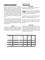
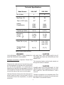
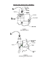
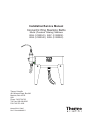
Installation/Service Manual
Concentric Ring Steaming Baths
Model (Precision Catalog) Numbers
2896 (51220041), 2897 (51220202)
2898 (51220042), 2899 (51220043)
Thermo Scientific
401 Millcreek Road, Box 649
Marietta, Ohio 45750
USA
Phone: 740-373-4763
Toll Free: 800-848-3080
FAX: 740-373-4189
Manual P/N 3173987
Rev.F Dated 29MAR07
NOTICE
THE MATERIAL IN THIS MANUAL IS FOR INFORMATION PURPOSES ONLY. THE CONTENTS
AND THE PRODUCT IT DESCRIBES ARE SUBJECT TO CHANGE WITHOUT NOTICE.
THERMO SCIENTIFIC MAKES NO REPRESENTATIONS OR WARRANTIES WITH RESPECT
TO THIS MANUAL. IN NO EVENT SHALL THERMO BE LIABLE FOR ANY DAMAGES, DIRECT
OR INCIDENTAL, ARISING OUT OF OR RELATED TO THE USE OF THIS MANUAL.
For repair information or replacement parts assistance from the manufacturer, call Technical Services using our
toll free telephone number.
888-213-1790
(FAX) 740-373-4189
REVISION STATUS
INDEX
DATE
AMENDED PAGES
A
NOTES
Initial release
C
3/99
D
10/99
E
7/05
34002565(667309411)
F
3/07
4 and 8
7
Update part numbers and manual
format
Update parts list for new kit no.'s
new manual #, manufacture location
added note to add shrink tubing,
updated heater illustration
Contents
INTRODUCTION .................................................................................................................. 1
UNPACKING AND DAMAGE .............................................................................................. 1
GENERAL INFORMATION .................................................................................................. 2
INSTALLATION ................................................................................................................... 2
WATER LEVEL REGULATOR INSTRUCTIONS & ILLUSTRATION ................................. 4
OPERATION ........................................................................................................................ 6
PARTS LIST ........................................................................................................................ 7
HEATER & 3HEAT SWITCH CONNECTIONS ............................................................................ 8
DIMENSIONAL DWG. FOR 4 & 8 HOLE BATHS TABLE MOUNTING .............................. 9
WARRANTY ....................................................................................................................... 10
INTRODUCTION
UNPACKING AND DAMAGE
Your satisfaction and safety are important to
Thermo and a complete understanding of this unit
is necessary to attain these objectives.
Save all packing material until unit is put into
service. This merchandise was carefully packed
and thoroughly inspected before leaving our
factory.
As the user of this apparatus, you have the
responsibility to understand the proper function
and operational characteristics of your bath. This
instruction manual should be thoroughly read and
all operators given adequate training before
attempting to place this unit in service. Awareness
of the stated cautions and warnings, and
compliance with recommended operating
parameters -- together with maintenance
requirements -- are important for safe and
satisfactory operation. The unit should be used for
its intended application; alterations or modifications
will VOID THE WARRANTY.
Responsibility for safe delivery was assumed by
the carrier upon acceptance of the shipment;
therefore, claims for loss or damage sustained in
transit must be made upon the carrier by the
recipient as follows:
Visible Loss or Damage: Note any external
evidence of loss or damage on the freight bill, or
express receipt, and have it signed by the carrier's
agent. Failure to adequately describe such external
evidence of loss or damage may result in the
carrier's refusing to honor your damage claim.
The form required to file such claim will be supplied
by the carrier.
WARNING
AS A ROUTINE LABORATORY PRECAUTION,
ALWAYS WEAR SAFETY GLASSES WHEN
WORKING WITH THIS APPARATUS.
Concealed Loss or Damage: Concealed loss or
damage means loss or damage which does not
become apparent until the merchandise has been
unpacked and inspected. Should either occur,
make a written request for inspection by carrier's
agent within 15 days of the delivery date; then file
a claim with the carrier since the damage is the
carrier's responsibility.
This product is not intended, nor can it be used, as
a sterile or patient connected device. In addition,
this apparatus is not designed for use in Class I, II
or III locations as defined by the National Electrical
Code.
If you follow the above instructions carefully, we
will guarantee our full support of your claim to be
compensated for loss or concealed damage.
DO NOT -- FOR ANY REASON -- RETURN THIS
UNIT WITHOUT FIRST OBTAINING
AUTHORIZATION. In any correspondence to
Thermo, please supply the nameplate data,
including catalog number and serial number.
1
INSTALLATION
GENERAL INFORMATION
WARNING
Precision Concentric Ring Steaming Baths are
designed to gently warm, melt, or concentrate
samples. Concentric rings accommodate various
sizes of glassware or evaporating dishes. Stainless
steel rings are flange-formed for a smooth fit. Four
hole bath openings become progressively larger
in 1" (25mm) increments, as each ring is removed
, to a maximum diameter of 5-1/8" (130mm). Eight
hole baths have maximum bath opening diameters
of 4-1/8" (105mm), 5-1/8" (130mm), and 6-1/8"
(156mm).
INSTALLATION SHOULD BE COMPLETED BY
QUALIFIED PERSONNEL ONLY.
Location: For maximum efficiency, the bath should
be installed on a level surface, and free as possible
from drafts or severe temperature changes which
can affect the performance of the bath.
A convenient source of water and electricity
facilities must be considered when choosing a
location for electrically heated models.
Adjustable water level regulator continuously
maintains desired liquid depths when connected
to a suitable supply source. Other construction
features include stainless steel bath body , copper
clad immersion heater, metal support stand, and
3-heat/off switch.
Since these baths are suitable for flush or recess
mounting in a bench top, table top, or hood, a
dimensional drawing for table top openings is
provided.
CAUTION
NOTE
EXERCISE CARE WHEN USING ACIDIC OR
CAUSTIC SOLUTIONS AS THEY WILL ATTACK
THE STAINLESS STEEL BATH BODY, THE
CONCENTRIC RING COVERS, AND ALSO THE
COPPER HEATER IF SERIOUS SPILLAGE INTO
THE BATH SHOULD OCCUR.
DUE TO OPTIONAL RECESS-MOUNTING OF
THE BATHS, SUPPORT STAND ASSEMBLY
AND HEATER SWITCH WIRING MUST BE
COMPLETED AT THE TIME OF INSTALLATION.
Catalog
Number
Description
Volts
Hz
Watts
Amps
3166420
4-Hole Bath
115
50/60
1100
9.2
3166563
4-Hole Bath
230
50/60
1100
4.6
3166421
8-Hole Bath
115
50/60
2000
16.6
3166422
8-Hole Bath
230
50/60
2000
8.3
2
Technical Specifications
Model Number
2896, 2897
2898, 2899
4
8
Max Temp. (°C)
100
100
Time to 100°C (min.)
40 *
58 *
No. of Holes
Heating
Characteristics
275W
550W
1000W
500W
1000W
2000W
Capacity, gal. (liters)
2 (7.6)
4 (15.1)
17 (43)
14.5 (37)
4 (10)
31 (78)
15 (38)
4 (10)
4 ea. 5 (13)
2 ea. 4 (10)
2 ea. 6 (15)
4 ea. 5 (13)
26 (12)
37 (17)
Dimensions
Overall
L
in. (cm.) W
D
Holes, Dia. in. (cm)
Shipping Weight
lbs. (kg)
*Medium setting maintains boiling.
WARNING
CAUTION
FOR PERSONAL SAFETY, THIS APPARATUS BE SURE THAT THE POWER SUPPLY IS OF
MUST BE PROPERLY GROUNDED.
THE SAME VOLTAGE AS SPECIFIED ON THE
NAMEPLATE.
Electrical Connections: (Important, Please Read
Carefully)
The immersion heater service leads extend out
through the bottom of the bath.
Determine the total amount of current being used
by other apparatus connected to the circuit that will
CAUTION
be used for this apparatus. It is critical that the
POWER MUST NOT BE SUPPLIED TO THE
added current demand (see nameplate) of this and
HEATER UNTIL UNIT IS ADEQUATELY FILLED
other equipment used on the same circuit does not
WITH WATER; HEATER BURNOUT WILL
exceed the rating of the fuse or circuit breaker.
OCCUR.
National Electrical Code should be observed for
The bath, as supplied, is not completely wired. This
proper fusing and size of service wires. All wire
procedure allows the customer to mount and wire
connections should be completed by a qualified
the switch in a convenient location.
electrician.
3
Slide the provided shrink tubing over the wires
indicated in the illustration on Page 8. Wire the
heater to the 3 heat switch provided and the switch
to the power source. (See wiring diagram on page
8). The heater locknut contains a grounding
terminal and a connection must be made to a well
grounded conduit system.
-Proceed with Step 2.
A cover plate is supplied for mounting the switch
in a standard electrical box (not provided) at a
convenient location.
2.
Insert the plastic tubing (coming from the bottom of the water level regulator) into the elbow connector (at the drain) & tighten the
elbow connector fitting firmly to insure a good
seal. (Tabletop unit can now be remounted
into table opening).
3.
Uncoil the flexible tubing & attach to 1/4" Hose
Barb Fitting (located at the top of water level
regulator) by using Hose Clamp.
4.
After filling bath with water, attach the other
end of the flexible tubing to water supply by
using hose clamp & turn on water supply. (MIN
is approx. 15 PSI, MAX is approx 75 PSI)
CAUTION
WHEN MOUNTING SWITCH TO SWITCH
COVER PLATE, DO NOT OVERTIGHTEN
SWITCH NUT, AS IT COULD CAUSE THE
SWITCH TO FAIL.
NOTE: Water line marking on the Water Level
Regulator is an indicator of the approx. water
level that will be maintained in bath. The assembly has been set to maintain approx. 1-3/
4" of water. To raise the set water level, loosen
thumbscrew & raise Water Level Regulator
to desired level (coincide with Water Line
mark) & tighten thumbscrew to hold Water
Level Regulator in place.
CAUTION
TO PREVENT LEAKAGE, BE SURE THE LARGE
LOCKNUT HOLDING THE HEATER IN PLACE
IS TIGHT.
WATER LEVEL REGULATOR
INSTRUCTIONS
INSTALLATION INSTRUCTIONS
NOTE: Air bubbles (created by steaming
water in bath) may form in plastic tube between bath & water level regulator. This does
not affect the operation of Water Level Regulator. If you wish to relieve air bubbles, loosen
thumbscrew on bracket raise Water Level
Regulator then lower to original position and
tighten thumbscrew.
Use the following steps along with Fig. 1 & 2
shown on page 5.
--FOR UNITS USING TABLE WITH LEGS-1.
Place Water Level Regulator Bracket. Assembly between the bottom of the bath body &
the top of the bath table frame. (Bracket should
be flush with back edge of the bath body, see
Fig. 1 Side View Note). You do not need to
remove the backing of the double-sided adhesive tape. The weight of a filled bath will
keep the bracket assembly in place.
-Proceed with Step 2.
FOR UNITS MOUNTED IN TABLETOP OR
COUNTER-1.
After cutting out countertop see Fig. 3 on page
9, remove backing of double sided tape on
bracket and attach to bath by pressing the
bracket firmly against the side & bottom of bath
body (Bracket should be flush with back edge
of bath body, see Fig.1 Side View Note).
4
WATER LEVEL REGULATOR ASSEMBLY
FIGURE 1
SIDE VIEW OF BATH
FIGURE 2
CUTAWAY FRONT VIEW OF BATH
5
OPERATION
Service and Maintenance
Step 1: Turn water source "ON" and adjust Water
Level Regulator to maintain water level (to replace
water lost in the bath due to evaporation).
The predominant cause of heater element failure
is operation without total immersion. When a heater
is operated in such a fashion there is insufficient
water to dissipate the large concentration of energy
in the element. This will cause the copper sheath
to become annealed soften and rupture. An
electrical short and heater failure will occur. This
condition is readily identified with a blue
discoloration and actual melting of the copper at
the point it is exposed to air. This failure IS NOT
covered by the warranty.
CAUTION
IF THE WATER LEVEL DROPS BELOW THE
HEATING ELEMENT; HEATER BURNOUT WILL
OCCUR.
Step 2: Turn switch knob to "high" position to bring
water to a boil.
The heater element is extracted by removing the
locknut retaining the heater to the bottom, and then
removing the heater coil by pushing up through
the hole in the bath bottom. It is then removed
through one of the large holes in the top of the
bath. A new element is replaced in like manner.
Replace the O-ring on the inside of bath bottom.
Step 3: Select switch position to maintain
vaporization without violent boiling.
Cleaning and Care of Stainless Steel
Occasionally there is a misunderstanding with
regards to the ability of stainless steel to withstand
attack from various materials.
Switch: When replacing, care should be taken to
tape wires, assuring proper replacement.
Stainless steel will resist corrosion, it is not
impervious to it.
It is the most practical and economical, relatively
speaking, material for fabrication of many lab items,
but for full life it must receive a certain amount of
care.
There are many chemical cleaners, but usually just
changing the water in a bath, or a periodic cleaning
with a non-scratching scouring powder such as
Bon Ami is satisfactory.
6
PARTS LIST
Part
Number
Qty.
3167048
1
Heater Assembly Kit
120 Volt, 1100 Watts, 4 Hole Bath
3161568
1
Heater Assembly Kit
240 Volt, 1100 Watts, 4 Hole Bath
3166980
1
Heater Assembly Kit
120 Volt, 2000 Watts, 8 Hole Bath
3166974
1
Heater Assembly Kit
240 Volt, 2000 Watts, 8 Hole Bath
3167276
1
Switch Assembly
3174885
1
Knob, Switch
3166211
1
Water Level Regulator Kit
3166186
1
Concentric Ring Kit, 4" Dia., Stainless
Steel
3166187
1
Concentric Ring Kit, 5" Dia., Stainless
Steel
3166215
1
Concentric Ring Kit, 6" Dia., Stainless
Steel
Description
7
HEATER AND 3 HEAT SWITCH CONNECTIONS
COMMON
8
DIMENSIONAL DRAWING FOR 4 & 8 HOLE BATHS
TABLE MOUNTING
E
DIMENSION CHART
BATH
TYPE
4 HOLE
8 HOLE
BATH TOP SIZE
TABLE OPENING
A
B
C
D
E
14 3/8
15
14 1/2
28 3/8
13 7/8
14 3/8
13 7/8
27 7/8
8
8 1/2
FIGURE 3
9
Rev. 3 2/07
REGISTERED
ISO
9001
If equipment service is required, please call your Technical Services Department at 1-888-213-1790 (USA and Canada) or
1-740-373-4763. We're ready to answer your questions on equipment warranty, operation, maintenance, service and special
application. Outside the USA, contact your local distributor for warranty information.
Your local Thermo Sales Office is ready to help with comprehensive site preparation information before your equipment
arrives. Printed instruction manuals carefully detail equipment installation, operation and preventive maintenance.
THIS WARRANTY IS EXCLUSIVE AND IN LIEU OF ALL OTHER WARRANTIES, WHETHER WRITTEN, ORAL OR
IMPLIED. NO WARRANTIES OF MERCHANTABILITY OR FITNESS FOR A PARTICULAR PURPOSE SHALL APPLY.
Thermo shall not be liable for any indirect or consequential damages including, without limitation, damages relating to lost
profits or loss of products.
Replacement or repair of components parts or equipment under this warranty shall not extend the warranty to either the
equipment or to the component part beyond the original warranty period. The Technical Services Department must give prior
approval for return of any components or equipment. At Thermo's option, all non-conforming parts must be returned to
Thermo Electron Corporation postage paid and replacement parts are shipped FOB destination.
During the first year, component parts proven to be non-conforming in materials or workmanship will be repaired or replaced
at Thermo's expense, labor included. Installation and calibration are not covered by this warranty agreement. The Technical
Services Department must be contacted for warranty determination and direction prior to performance of any repairs.
Expendable items, glass, filters and gaskets are excluded from this warranty.
The Warranty Period starts two weeks from the date your equipment is shipped from our facility. This allows for shipping time
so the warranty will go into effect at approximately the same time your equipment is delivered. The warranty protection
extends to any subsequent owner during the first year warranty period.
THERMO FISHER SCIENTIFIC STANDARD PRODUCT WARRANTY
Rev. 3 2/07
REGISTERED
ISO
9001
If equipment service is required, please call your Technical Services Department at 1-888-213-1790 (USA or Canada), or
1-740-373-4763. We're ready to answer your questions on equipment warranty, operation, maintenance, service and special application. Outside the USA, contact your local distributor for warranty information.
Your local Thermo Sales Office is ready to help with comprehensive site preparation information before your equipment
arrives. Printed instruction manuals carefully detail equipment installation, operation and preventive maintenance.
THIS WARRANTY IS EXCLUSIVE AND IN LIEU OF ALL OTHER WARRANTIES, WHETHER WRITTEN, ORAL OR
IMPLIED. NO WARRANTIES OF MERCHANTABILITY OR FITNESS FOR A PARTICULAR PURPOSE SHALL APPLY.
Thermo shall not be liable for any indirect or consequential damages including, without limitation, damages relating to lost
profits or loss of products.
Replacement or repair of components parts or equipment under this warranty shall not extend the warranty to either the
equipment or to the component part beyond the original warranty period. The Technical Services Department must give prior
approval for return of any components or equipment. At Thermo's option, all non-conforming parts must be returned to
Thermo postage paid and replacement parts are shipped FOB destination.
During the first year, component parts proven to be non-conforming in materials or workmanship will be repaired or replaced
at Thermo's expense, labor excluded. Installation and calibration are not covered by this warranty agreement. The Technical
Services Department must be contacted for warranty determination and direction prior to performance of any repairs.
Expendable items, glass, filters, reagents, tubing, and gaskets are excluded from this warranty.
The Warranty Period starts two months from the date your equipment is shipped from our facility. This allows for shipping
time so the warranty will go into effect at approximately the same time your equipment is delivered. The warranty protection extends to any subsequent owner during the first year warranty period. Dealers who stock our equipment are allowed
an additional six months for delivery and installation, provided the warranty card is completed and returned to the Technical
Services Department.
THERMO FISHER SCIENTIFIC INTERNATIONAL DEALER WARRANTY