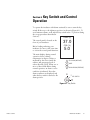
1
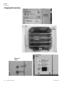
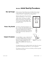
User Manual
Midi 40 Series
CO2 Incubator
Operating and Maintenance Manual 7003403 Rev. 7
Visit us online to register your warranty
www.thermoscientific.com/labwarranty
Preface
Models covered by this manual:
Model 3403
115V
Model 3404
208/230V
MANUAL NUMBER 7003403
7
30073/IN-4491
7/7/15
Added stacking hardware kit to Parts List
ccs
6
30073/IN-4491
7/28/14
Clarified specs in Location for stacking
ccs
5
26439/IN-4050
2/5/13
Updated uniformity in Specifications
ccs
4
28251/IN-4219
8/30/12
Removed RS-485
ccs
3
28728
6/18/12
Updated Calibration sections - pg 6-4 through 6-6
ccs
2
27796/IN-4127
10/3/11
Tubing size from 3/16 to 1/4” - pgs 4-1 and 4-3
ccs
--
--
6/10/10
Corrected typo in Table 6-1 on pg 6-2 - removed O2 (per D. Wernerspach)
ccs
--
--
3/22/10
Clarifications and corrections to pg 1-2 table dims
ccs
1
26174
2/18/10
Clarifications and corrections per N. Pisani (corrected reversed ext cm dims 3/17)
ccs
0
--
12/1/09
Original, was 33602H01 Rev. A
ccs
REV
ECR/ECN
DATE
DESCRIPTION
By
Thermo Scientific
Midi 40 CO2 Incubator
i
Preface
CAUTION
Contains Parts and Assemblies
Susceptible to Damage by
Electrostatic Discharge (ESD)
Important Read this instruction manual. Failure to read, understand and follow the instructions in this manual
may result in damage to the unit, injury to operating personnel, and poor equipment performance. s
Caution All internal adjustments and maintenance must be performed by qualified service personnel. s
Material in this manual is for information purposes only. The contents and the product it describes are subject
to change without notice. Thermo Fisher Scientific makes no representations or warranties with respect to this
manual. In no event shall Thermo be held liable for any damages, direct or incidental, arising out of or related
to the use of this manual.
©2009 Thermo Fisher Scientific. All rights reserved.
ii
Midi 40 CO2 Incubator
Thermo Scientific
Preface
Important operating and/or maintenance instructions. Read the accompanying text carefully.
Potential electrical hazards. Only qualified persons should perform procedures associated with this
symbol.
Equipment being maintained or serviced must be turned off and locked off to prevent possible injury.
Hot surface(s) present which may cause burns to unprotected skin, or to materials which may be
damaged by elevated temperatures.
Marking of electrical and electronic equipment, which applies to electrical and electronic equipment
falling under the Directive 2002/96/EC (WEEE) and the equipment that has been put on the market
after 13 August 2005.
This product is required to comply with the European Union’s Waste Electrical & Electronic
Equipment (WEEE) Directive 2002/96/EC. It is marked with the WEEE symbol. Thermo Fisher
Scientific has contracted with one or more recycling/disposal companies in each EU Member State
European Country, and this product should be disposed of or recycled through them. Further
information on Thermo’s compliance with this directive, the recyclers in your country and
information on Thermo Scientific products will be available at www.thermofisher.com.
4
Always use the proper protective equipment (clothing, gloves, goggles, etc.)
4 Always dissipate extreme cold or heat and wear protective clothing.
4 Always follow good hygiene practices.
4 Each individual is responsible for his or her own safety.
Thermo Scientific
Midi 40 CO2 Incubator
iii
Preface
Do You Need Information or Assistance on
Thermo Scientific Products?
If you do, please contact us 8:00 a.m. to 6:00 p.m. (Eastern Time) at:
1-740-373-4763
1-800-438-4851
1-740-373-4189
http://www.thermo.com
[email protected]
Direct
Toll Free, U.S. and Canada
FAX
Internet Worldwide Web Home Page
Service E-Mail Address
Our Sales Support staff can provide information on pricing and give you quotations. We can
take your order and provide delivery information on major equipment items or make
arrangements to have your local sales representative contact you. Our products are listed on the
Internet and we can be contacted through our Internet home page.
Our Service Support staff can supply technical information about proper setup, operation or
troubleshooting of your equipment. We can fill your needs for spare or replacement parts or
provide you with on-site service. We can also provide you with a quotation on our Extended
Warranty for your Thermo Scientific products.
Whatever Thermo Scientific products you need or use, we will be happy to discuss your
applications. If you are experiencing technical problems, working together, we will help you
locate the problem and, chances are, correct it yourself...over the telephone without a service
call.
When more extensive service is necessary, we will assist you with direct factory trained
technicians or a qualified service organization for on-the-spot repair. If your service need is
covered by the warranty, we will arrange for the unit to be repaired at our expense and to your
satisfaction.
Regardless of your needs, our professional telephone technicians are available to assist you
Monday through Friday from 8:00 a.m. to 6:00 p.m. Eastern Time. Please contact us by
telephone or fax. If you wish to write, our mailing address is:
Thermo Scientific
Controlled Environment Equipment
401 Millcreek Road, Box 649
Marietta, OH 45750
International customers, please contact your local Thermo Scientific distributor.
iv
Midi 40 CO2 Incubator
Thermo Scientific
Table of Contents
Thermo Scientific
Section 1
Introduction . . . . . . . . . . . . . . . . . . . . . . . . . . . . . . . . . . . . . . . . . . . . . . . . .1-1
Requirements . . . . . . . . . . . . . . . . . . . . . . . . . . . . . . . . . . . . . . . . . . .1-1
Specifications . . . . . . . . . . . . . . . . . . . . . . . . . . . . . . . . . . . . . . . . . . .1-2
Section 2
Safety Precautions . . . . . . . . . . . . . . . . . . . . . . . . . . . . . . . . . . . . . . . . . . .2-1
Section 3
Operating Standards . . . . . . . . . . . . . . . . . . . . . . . . . . . . . . . . . . . . . . . . . .3-1
Section 4
Pre-Installation . . . . . . . . . . . . . . . . . . . . . . . . . . . . . . . . . . . . . . . . . . . . . .4-1
Included Parts . . . . . . . . . . . . . . . . . . . . . . . . . . . . . . . . . . . . . . . . . .4-1
Location . . . . . . . . . . . . . . . . . . . . . . . . . . . . . . . . . . . . . . . . . . . . . . .4-2
Set-Up . . . . . . . . . . . . . . . . . . . . . . . . . . . . . . . . . . . . . . . . . . . . . . . .4-2
Wiring . . . . . . . . . . . . . . . . . . . . . . . . . . . . . . . . . . . . . . . . . . . . . . . .4-2
Gas Supplies . . . . . . . . . . . . . . . . . . . . . . . . . . . . . . . . . . . . . . . . . . . .4-2
CO2 Gas Connections . . . . . . . . . . . . . . . . . . . . . . . . . . . . . . . . . . .4-3
Component Locations . . . . . . . . . . . . . . . . . . . . . . . . . . . . . . . . . . . .4-4
Section 5
Initial Start-Up Procedures . . . . . . . . . . . . . . . . . . . . . . . . . . . . . . . . . . . .5-1
Start-Up Prompts . . . . . . . . . . . . . . . . . . . . . . . . . . . . . . . . . . . . . . . .5-1
Power / Key Switch . . . . . . . . . . . . . . . . . . . . . . . . . . . . . . . . . . . . . .5-1
Setpoint Parameters . . . . . . . . . . . . . . . . . . . . . . . . . . . . . . . . . . . . . .5-1
Section 6
Key Switch and Control Operation . . . . . . . . . . . . . . . . . . . . . . . . . . . . .6-1
Restore Function . . . . . . . . . . . . . . . . . . . . . . . . . . . . . . . . . . . . . . . .6-3
Service Mode Parameters . . . . . . . . . . . . . . . . . . . . . . . . . . . . . . . . . .6-3
Setpoint and Alarm Programming . . . . . . . . . . . . . . . . . . . . . . . . . .6-3
Calibration (Optional) . . . . . . . . . . . . . . . . . . . . . . . . . . . . . . . . . . . .6-4
Access Program or Service Menu . . . . . . . . . . . . . . . . . . . . . . . . . .6-4
Temperature Calibration . . . . . . . . . . . . . . . . . . . . . . . . . . . . . . . . .6-5
CO2 Calibration . . . . . . . . . . . . . . . . . . . . . . . . . . . . . . . . . . . . . . .6-6
Midi 40 CO2 Incubator
v
Table of Contents
vi
Midi 40 CO2 Incubator
Section 7
Control Systems Theory . . . . . . . . . . . . . . . . . . . . . . . . . . . . . . . . . . . . . . .7-1
Overtemperature Monitoring System . . . . . . . . . . . . . . . . . . . . . . . . .7-1
CO2 Recovery (after door opening) . . . . . . . . . . . . . . . . . . . . . . . . . .7-2
CO2 Control System . . . . . . . . . . . . . . . . . . . . . . . . . . . . . . . . . . . . .7-2
Door Heat System . . . . . . . . . . . . . . . . . . . . . . . . . . . . . . . . . . . . . . .7-2
Section 8
Maintenance . . . . . . . . . . . . . . . . . . . . . . . . . . . . . . . . . . . . . . . . . . . . . . . .8-1
CO2 Filter Replacement . . . . . . . . . . . . . . . . . . . . . . . . . . . . . . . . . .8-2
Cleaning . . . . . . . . . . . . . . . . . . . . . . . . . . . . . . . . . . . . . . . . . . . . . . .8-2
Door Seal Check . . . . . . . . . . . . . . . . . . . . . . . . . . . . . . . . . . . . . . . .8-3
Fuses . . . . . . . . . . . . . . . . . . . . . . . . . . . . . . . . . . . . . . . . . . . . . . . . .8-3
Section 9
Parts List . . . . . . . . . . . . . . . . . . . . . . . . . . . . . . . . . . . . . . . . . . . . . . . . . . . .9-1
Section 10
Warranty Information . . . . . . . . . . . . . . . . . . . . . . . . . . . . . . . . . . . . . . . .10-1
Thermo Scientific
Section 1
Introduction
These incubators are designed to create a stable, reliable environment for
cell culture applications. They operate at temperatures ranging from 5°C
above ambient temperature to +60°C, accurate to ±0.2°C. The gas system
controls within ±0.1% of measurable setpoint.
•
Thermal conductivity sensor provides stable, automatic injection of
CO2.
•
Automatic Gas Shutoff control turns off the gas supply when the inner
glass door is opened to prevent wasting the control gas.
•
Alarms:
–
High and low level CO2 setpoint alarms, adjustable.
–
High and low temperature alarms; high alarm can be set by user.
–
Battery Low alarm; control system has tested the alarm battery and
determined that it should be replaced.
Caution The function of the alarm battery is to operate the display and
alarm system ONLY during a power loss, while the key switch is in the
On or Alarm position. This battery system will not power the heaters, fan
motor or gas control system. Only qualified service technicians should
replace this battery. Replacement instructions and batteries are available
from Thermo Scientific. s
Requirements
•
A high quality two-stage, low pressure 15 psig (1.056 kg/cm2) pressure
regulator is required for proper operation of the CO2 gas supply.
•
In-line gas supply filters must be used on the CO2 supply to prevent
damage to the solenoid valve(s):
– Type: Microbiological
– Specification: 0.3 micron
– Location: rear of unit
•
Thermo Scientific
CO2 used in the incubator must be at least 99.9% pure.
Midi 40 CO2 Incubator
1-1
Section 1
Introduction
Specifications
Technical Specifications
Model 3403
Model 3404
Dimensions
Exterior (w x h x d) inch/cm
23.5 x 18 x 18.5 (59.7 x 45.7 x 47)
Interior (w x h x d) inch/cm
14 x 14 x 12 (35.5 x 35.5 x 30.5)
Construction
Cabinet configuration
Interior
Benchtop
non-corrosive stainless steel, type 304, mirror finish
Interior volume
Chamber capacity
1.4 cu ft (39.6 l)
Shelves
4
Construction
stainless steel, perforated
Shelf dimensions (w x d ) inch/cm
13.5” x 11.5” (34.3 x 29.2)
Surface area per shelf
1.08 sq ft (0.1 sq m)
Temperature
Range
5°C above ambient to 60°C
Control
±0.1°C
Uniformity
Alarm
±0.5°C @ 37°C
user programmable high/low
CO2
Range
0-20%
Control
±0.1%
Sensor
long life thermal conductivity sensor
Uniformity
Inlet pressure required
0.10%
15 PSIG (1.0 bar), 99.5 medicinal grade CO2
Inlet air filtration
0.3 micron anti-microbial filter
Alarm
user programmable high/low
Humidity
rH
Source
to 95% @ 37°C
humidity pan, removable
Electrical
Rated voltage
115V, 60Hz
208/230V, 50/60Hz
Amps/breaker
1.5/15
1.0/15
Weight
Net
60 lbs. (27kg)
Shipping
70 lbs. (32kg)
Warranty
1 year
All specifications are subject to change without notice.
1-2
Midi 40 CO2 Incubator
Thermo Scientific
Section 2
Safety Precautions
In this manual and on labels attached to this product, the words
WARNING and CAUTION mean the following:
•
WARNING: a potentially hazardous situation which, if not avoided,
could result in serious injury or death.
•
CAUTION: a potentially hazardous situation which, if not avoided,
may result in minor or moderate injury or damage to the equipment.
The following symbols are used in caution, warning and informational
labels attached to the incubator:
caution, info
on
electrical hazard
off
hot surface
alternating
current
earth ground
protective conductor terminal
Figure 1-1. Symbols Used in Labels on Incubator
Before installing, using or maintaining this product, please be sure to read
this manual and product warning labels carefully. Failure to follow these
instructions may cause this product to malfunction, which could result in
injury or damage.
Thermo Scientific
Midi 40 CO2 Incubator
2-1
Section 2
Safety Precautions
Below are important safety precautions that apply to this product:
•
Use this product only in the way described in the product literature
and in this manual. Before using it, verify that this product is suitable
for its intended use.
•
Do not modify system components, especially the controller. Use
OEM exact replacement equipment or parts. Before use, confirm that
the product has not been altered in any way.
•
Disconnect the unit from all power sources before cleaning,
troubleshooting, or performing other maintenance on the product or
its controls. To disconnect power supply to the incubator, unplug the
supply cord at the back of the incubator. Note that turning the key
switch on the front control panel to the Off position is not sufficient
to disconnect power.
Warning The user is responsible for carrying out appropriate
decontamination procedures when hazardous materials are spilled on or
inside the incubator. s
2-2
Midi 40 CO2 Incubator
Thermo Scientific
Section 3
Operating Standards
The incubators described in this manual are classified for use as stationary
equipment in a Pollution Degree 2 and Overvoltage Category II
environment, according to the UL3101-1 and IEC 664 standards.
These units are designed to operate under the following environmental
conditions:
Thermo Scientific
•
Indoor use
•
Altitude up to 2000m
•
Maximum relative humidity 80% for temperatures up to 31°C
•
Main supply voltage fluctuations not to exceed 10% of the nominal
voltage.
Midi 40 CO2 Incubator
3-1
Section 4
Pre-Installation
At delivery, examine the exterior for physical damage while the carrier’s
representative is present. If exterior damage is present, carefully unpack
and inspect the unit and all accessories for damage. If there is no exterior
damage, unpack and inspect the equipment within five days of delivery. If
you find any damage, keep the packing materials and immediately report
the damage to the carrier. Do not return goods to the manufacturer
without written authorization. When submitting a claim for shipping
damage, request that the carrier inspect the shipping container and
equipment.
Included Parts
The following items are packaged and shipped inside the incubator
cabinet:
• This manual
• Shelves and shelf brackets
• 1/4 in. (6.35 mm) ID clear tubing for the gas connection
• Cordset
• 5” round humidity pan
• Additional CO2 sensor gasket
• CO2 disposable filter 99.97
Filter
Additional
gasket
Operating
manual
Humidity
pan
Cordset
Tubing
Figure 4-1. Included Components (shelves and brackets not shown)
Thermo Scientific
Midi 40 CO2 Incubator
4-1
Section 4
Pre-Installation
Set-Up
Location
Remove shelves from the inside of the incubator and clean the chamber.
Shelves and brackets can be autoclaved.
Install the unit in a level area free from vibration with a minimum of three
inches (7.6 cm) of space on the sides and rear, and twelve inches (30.5 cm)
at the top. The floor must be able to support 40 PSI (single chamber
incubator) or 75 PSI (stack of two incubators with the addition of stacking
hardware kit).
Be sure to position the incubator so that the power cord (mains disconnect)
is easily accessible to disconnect power.
Do not position the equipment in direct sunlight or near any HVAC
duct/diffusers. The ambient temperature range at the work location must
be 59 to 90°F (15 to 32°C).
Gas Supplies
Verify that the incubator CO2 gas supplies are available near the
installation area. The required gas supply pressure is 15 PSI, controlled by
a high-quality, two-stage regulator suitable for the connected input gas.
Warning Do not connect the gas at this time.
Wiring
s
Caution Connect the equipment to the correct power source. Be sure to
operate the incubator at the voltage specified on the dataplate. Incorrect
voltage can result in severe damage to the equipment. s
Warning For personal safety and trouble-free operation, this unit must be
properly grounded before it is used. Failure to ground the equipment may
cause personal injury or damage to the equipment. Always conform to the
National Electrical Code and local codes. Do not connect the unit to
overloaded power lines. s
The incubators described in this manual are available with the following
volatages: 115VAC, single-phase, 60Hz, 3A and 208/230VAC, single
phase, 50/60Hz, 2A
Be sure to check your dataplate to verify the correct voltage for your unit.
Always connect the unit to a dedicated (separate) circuit. Do not exceed
the electrical and temperature ratings printed on the dataplate located near
the upper hinge of the unit. Electrical codes require fuse or circuit breaker
protection for branch circuit conductors. Use time delay fuses for #12
AWG circuits.
4-2
Midi 40 CO2 Incubator
Thermo Scientific
Section 4
Pre-Installation
CO2 Gas Connections
CO2 gas connection(s) are located at the rear of the unit.
Note The required gas supply pressure is 15 PSI. Make sure the supply is
available in the installation area. s
To install the CO2 connections, complete the following steps:
1. Locate the included 1/4 in. (6.3mm) interior diameter tubing.
2. Cut a small length (approximately 6 in. [15cm]) from the roll of 1/4
in. (6.3mm) ID tubing.
3. Pull the cap off the gas connection port at the rear of the incubator
and attach one end of the tubing to the gas connection port.
4. Connect the opposite end of the tubing to a high-quality input gas
filter (0.3 micron supplied). Note that the side of the filter marked
“IN” faces the incoming gas connection, not the back of the incubator
(refer to Figure 1-2).
1/4 in. ID Tubing
Gas Filter
Figure 1-2. CO2 Gas Connections
5. Use the remaining 1/4 in. ID tubing to connect the input gas to the
gas filter. Keep the tubing length as short as possible to minimize the
pressure drop.
Caution DO NOT turn on the gas supply at this time. s
Thermo Scientific
Midi 40 CO2 Incubator
4-3
Section 4
Pre-Installation
Component Locations
dataplate
on left side
Inside
Chamber
sensor
humidity pan
Lower back
of unit
Upper back
of unit
Sample Port
Power
inlet
CO2 inlet
4-4
Midi 40 CO2 Incubator
Thermo Scientific
Section 5
Start-Up Prompts
Initial Start-Up Procedures
On first start-up of the incubator, the control display will go through
several prompts to guide you through the entire set-up process, from
leveling the incubator to adjusting the operating parameters.
During normal operation, the control panel
display looks like Figure 5-1. The next section
explains all the control functions available
during normal operation. On initial start-up,
however, a series of prompts displays. This
section explains the start-up prompts and the
procedures to follow.
Power / Key Switch
TEMP (C)
37.0
CO2 (%)
5.0
Turn the key switch (shown in Figure 5-1) to
the “1” position. Press and hold the up arrow
button to initiate the special start-up prompts. If
a temperature displays instead of a start-up
prompt, the up arrow button hasn’t been held
long enough. Turn the key switch back to “O”
and try again.
key switch
O
Setpoint Parameters
I
A prompt displays to accept or adjust the values
of several operating parameters. In each case,
press the up or down arrow buttons (increase or
Figure 5-1. Control Panel
decrease) to change a displayed value. Press
Mode when the displayed value is the one
desired. The modifiable value is always the one
flashing.
If a displayed parameter is not adjusted and 60 seconds elapse, the software
registers the existing default value and moves to the next parameter.
If no changes are needed to the factory-set defaults, press Mode repeatedly
until the end of the prompts.
Thermo Scientific
Midi 40 CO2 Incubator
5-1
Section 5
Initial Start-Up Procedures
Setpoint Parameters
(continued)
The adjustable parameters are:
•
Temperature (default 37ºC)
•
Warm alarm (default 40ºC; cannot deviate from the temperature
setpoint by less than 0.3ºC)
•
Cold alarm (default 34ºC; cannot deviate from the temperature
setpoint by less than 0.3ºC)
•
CO2 (default 5%)
•
High CO2 alarm (default 6%; cannot deviate from the CO2 setpoint
by less than 1%)
•
Low CO2 alarm (default 4%; cannot deviate from the CO2 setpoint
by less than 1%)
When parameter adjustments are complete, the screen returns to the
normal display (Figure 5-1). An additional message indicates that the
stabilization period has begun.
During this initial stabilization period, leave the door closed.
5-2
Midi 40 CO2 Incubator
Thermo Scientific
Key Switch and Control
Operation
Section 6
To operate the incubator with alarms activated, be sure to turn the key
switch all the way to the rightmost position (as shown in Figure 6-1). To
avoid nuisance alarms, work with the key switch in the “I” position during
the set-up procedures described in
Section 5.
TEMP (C)
The control panel is located on the
front of your incubator.
37.0
Before loading and using your
incubator, be sure to take some time
to review the control panel functions.
The main display, during normal
operation, shows: cabinet
temperature in degrees Celsius, as
measured by the sensor inside the
cabinet; and percentage levels of
carbon dioxide (CO2). When one or
more of these fields flashes during
normal operation, an alarm or error
condition is indicated. Note that
alarm conditions are displayed only
when the key switch is turned to the
alarm position.
CO2 (%)
5.0
UP ARROW (INCREASE)
MODE
DOWN ARROW (DECREASE)
O
I
KEY SWITCH
Figure 6-1. Key Switch
Thermo Scientific
Midi 40 CO2 Incubator
6-1
Section 6
Key Switch and Control Operation
In programming mode (described in detail in Table 61) the main display changes to show the setpoint being
viewed and related alarm setpoints. For example
(Figure 6-2):
Set Temp
SETPOINT:
37.0C
40.2C
The first value displayed is the temperature setpoint;
33.8C
the next two values are the high temp alarm and low
temp alarm setpoints. The flashing value is one that
can be changed, using the up and down arrow buttons. Figure 6-2.
Programming Mode
The up and down arrow buttons are used to change
setpoint values in programming mode and for various display functions.
The Mode pushbutton is used: to silence an audible alarm; to enter
programming and service modes; and in combination with the other
buttons for various display functions.
For full descriptions of display, programming, and service functions, refer
to Tables 6-1, 6-2, and 6-3.
Table 6-1. Control Panel Display
Function
Meaning
Sequence
Normal operation
Default display while incubator is running
Cold excursion
Show coldest cabinet temperature since
last startup or reset
Press
Display shows cold excursion while button is pressed.
Warm excursion
Show warmest cabinet temperature since
last startup or reset
Press
Display shows warm excursion while button is pressed.
Mode
Silence audible alarm
Press Mode
Display shows current values, alarm or error field
continues to flash.
Reset
Return to default display after excursion or alarm condition
Press
and
simultaneously
Excursion values are reset; display shows current values.
Display flashes twice
6-2
Midi 40 CO2 Incubator
—
Display
Display shows cabinet temperature, CO2, Relative
Humidity.
Thermo Scientific
Section 6
Key Switch and Control Operation
Setpoint and Alarm
Programming
To enter Program mode, press and hold the MODE button until the
display indicates it is changing to Program mode. Press Mode repeatedly
to scroll through the available functions. Exit Program mode by scrolling
through all available functions and parameters using the Mode button, or
the display will automatically return to normal operating mode 30 seconds
after the last key entry.
Table 6-2. Setpoint and Alarm Programming Functions
Function
Programming Sequence
Adjust temperature setpoint
Enter programming mode by pressing Mode and holding for 5 seconds. On release, the current temperature
setpoint value flashes in the display; use
and
to adjust it.
Adjust warm alarm setpoint
Press Mode again. The current warm alarm setpoint value then flashes in the display; use
and
There is a minimum deviation of 0.3º C between each alarm setpoint and the temperature setpoint.
to adjust it.
Adjust cold alarm setpoint
Press Mode again. The current cold alarm setpoint value then flashes in the display; use
and
to adjust it.
There is a minimum deviation of 0.3º C between each alarm setpoint and the temperature setpoint.
Adjust CO2 setpoint
Press Mode again. The display changes to display CO2 setpoint and high and low CO2 alarm setpoints, with the
and
to adjust it. There is a minimum deviation of 1% between each
operating CO2 setpoint flashing. Use
alarm setpoint and the operating CO2 setpoint.
Adjust CO2 high alarm setpoint
Press Mode again. The current high CO2 alarm setpoint then flashes; Use
and
to adjust it. There is a
minimum deviation of 1% between each alarm setpoint and the operating CO2 setpoint.
Adjust CO2 low alarm setpoint
Press Mode again. The current high CO2 low setpoint then flashes; Use
and
deviation of 1% between each alarm setpoint and the operating CO2 setpoint.
to adjust it. There is a minimum
Set Temp offset
Press Mode again. The display changes to display temperature offset (for calibration purposes). Use
adjust it.
and
Set CO2 offset
Press Mode again. The display changes to display CO2 offset (for calibration purposes). Use
to adjust it.
Service Mode
Parameters
and
to
Service mode can be entered from Program mode by pressing Mode and
holding for 5 seconds.Pressing Mode repeatedly scrolls through the
available functions. For any modifiable parameter, the up and down arrow
buttons can be used to adjust the value. The display automatically returns
to normal operating mode 30 seconds after the last key entry, or after
scrolling through all available functions and parameters.
Table 6-3. Service Parameters
Parameter
Notes
SN
Serial number.
Check Sum
Checksum to identify firmware version
PWM Info
CO2 sensor and excursion information
Restore Function
When the incubator is first powered up, all factory-set program parameter
defaults can be restored as follows:
Table 6-4. Restore Defaults
Function
Restore program defaults
Thermo Scientific
Sequence
simultaneously,
Press
and
hold for five seconds
Notes
Restores original (factory-set) values of all program parameters.
Midi 40 CO2 Incubator
6-3
Section 6
Key Switch and Control Operation
Calibration (Optional)
The Midi-40 Incubator utilizes a Thermal Conductivity (TC) CO2 sensor.
This style of CO2 sensor is adversely affected by changes in temperature
and relative humidity (RH). Therefore it is necessary to verify the
temperature calibration first and then wait for the passive RH inside the
chamber to stabilize, after any adjustment is made to temperature settings.
It is recommended that a full CO2 calibration procedure be performed:
•
After replacing the CO2 sensor or main micro board.
•
If, after re-setting a CO2 calibration offset and the offset calibration
does not improve the true measured accuracy.
•
If the interior RH condition is changed by adding or removing the RH
water pan to convert from a wet to dry condition.
Caution The full zero/span calibration procedure requires the user to access
the Program and Service Mode menu. s
Access Program or
Service Menu
To access the Service Mode, you first must enter Program mode. Press and
hold the Mode key for approximately five seconds until “Program Mode;”
is displayed. Release the key.
Next press and hold the Mode key again for approximately six seconds
until “Service Mode;” is displayed. Release the key.
Note If user does not push any keys after approximately thirty seconds, the
display will revert back to the normal Run mode . If a value was changed,
whatever value was last displayed will be stored as the new setting.
6-4
Midi 40 CO2 Incubator
Thermo Scientific
Section 6
Key Switch and Control Operation
Temperature Calibration
1. Ensure shelf support system and empty shelves are in place
2. Fill humidity pan approximately halfway full with distilled water and
position the RH pan on the incubator chamber floor and centered.
3. Install reference temperature sensor into the geometric center of the
chamber ensuring the sensor is not touching any shelves and is
measuring air temp only.
Note There is no access port located on a Midi-40 incubator to permit
passing cables through. Therefore a user must pass their independent
calibration temperature sensor cable through the inner and outer door
gasket seal. If access to a flat or thin style cable is not available, this may
lead to humidity escaping the inner chamber thus causing condensation to
form on the glass door or between the inner and outer doors surfaces. If a
thin style cable is not available, attempt to seal around the cable using
some perma-gum style putty (part # 13014) to help seal the passing of the
cable through the door gasket seal.
4. After power is connected, turn key switch from (0) to (I) On position.
5.) To set or adjust the Temp setpoint, enter Program mode. The first
menu is “Set Temp Setpoint”. Using the increment up arrow or the
decrement down arrow, adjust setting to desired temperature.
Continue to press the Mode button to advance from menu to menu to
exit, or wait 30 seconds and system will default to normal Run menu.
6. Set CO2 control set point in Program mode to 0.0% to keep CO2
injection solenoid off. It is highly recommended NOT to connect the
CO2 supply at this time.
7. Allow for temperature to stabilize;
a. Start-Up - Allow 12 hours for the temperature in the cabinet to
stabilize before proceeding.
b. Operating Unit - Allow at least two hours after the display reaches
setpoint for the temperature to stabilize before proceeding.
8. Enter Program Mode, go to “Set Temp OFFSET” option and press
the up/down arrow to match the display to a calibrated instrument.
9. For any offset adjustments made, allow at least 1 hour between
adjustments to permit the unit to stabilize again.
10. After the temperature is calibrated, it is recommended to remove the
temp sensor from the inner chamber to ensure the humidity inside the
chamber is not passing through the door seal. TC CO2 sensors require
stable temp and RH environment to ensure accurate calibration!
Thermo Scientific
Midi 40 CO2 Incubator
6-5
Section 6
Key Switch and Control Operation
CO2 Calibration
1. After performing the Temperature calibration first, ensuring the unit
has stabilized and the outer and inner door has not been opened for at
least two hours, proceed to zero the CO2 sensor.
2. Enter the Program mode, press Mode key until “Set CO2 OFFSET” is
displayed. Using the increment or decrement keys, make offset read
0.0%. Exit Program mode back to normal Run mode.
3a. Enter the “Service Mode”, press Mode key until “Zero CO2TC
Sensor” is displayed. Press the decrement key to zero, then press the
increment key to accept. The display should read zero micro-volts
(0uV). IMPORTANT NOTE You must complete the next step to fully
zero the CO2 sensor! s
3b. Press the increment key to set the new zero micro-volt (uV) value and
then press the decrement key to accept. Repeat this step until you get
repeating micro-volt values that are within ±50uV of each other. If the
uV values are greater than 50 digits, this indicates that the Temp/RH
has not fully stabilized inside the chamber and you should wait longer
for the Temp/RH to stabilize.
4. In “Service Mode”, press the Mode key again to display “Span
CO2TC Sensor”. Adjust CO2 span to read 975uV.
5. Press Mode key to exit Service mode, or wait 30 seconds for auto exit.
6. Connect CO2 supply and ensure CO2 gas pressure is set at 15psig, set
CO2 setpoint to desired setpoint, e.g. 5.0%.
7. Allow system to stabilize at least 1 hour after unit display shows set
point. Ensure that no door openings occur during this stabilization
period.
8. Just before taking a CO2 gas sample with your CO2 calibration handheld meter or FYRITE, lower the CO2 control set point in Program
mode 1.0% below your current set point, e.g. from 5% to 4%. This
step is necessary to prevent CO2 gas injection during the calibration of
the unit.
6-6
Midi 40 CO2 Incubator
Thermo Scientific
Section 6
Key Switch and Control Operation
CO2 Calibration
(continued)
IMPORTANT NOTE During the sampling of the chamber with your
FYRITE or hand-held calibration meter, the CO2 value shown on the unit
display will most likely drop a few tenths of a percent from e.g. 5% CO2
to maybe 4.5%, depending on how many FYRITE measurements/
aspirations you take, or depending on how long you leave your hand-held
calibration meter aspiration pump running. It is recommended that you
take 2-3 FYRITE measurements and or leave your CO2 hand-held meter
sampling the interior chamber for approx 1.5 to 2 minutes but no greater
than 3 minutes. After obtaining your calibration readings, remove the
tubing from CO2 sample port and cap the port. Allow the unit CO2
displayed value to stabilize, waiting approximately 3 minutes before
proceeding with the CO2 calibration offset in the next step!
9. Enter Service Mode, press Mode key until “Span CO2TC Sensor” is
displayed. Using the increment or decrement keys, adjust the span
until the correct CO2 % level is indicated.
10. Press Mode key to exit Service Mode, or wait 30 seconds for auto exit.
11. To verify if the new CO2 calibration works correctly, open both outer
and inner doors for at least 30 seconds, close the doors and wait a
minimum of two hours permitting the temperature and RH to
stabilize.
12. After two hours, sample the CO2 via the sample port with calibration
instrument; remember to reduce CO2 set point 1.0% below your
actual set point to avoid injecting gas during your measurement check.
13. If a small offset adjustment between (0.1 to 0.5%) is necessary, enter
Program mode, press Mode key until “Set CO2 OFFSET” is
displayed. Using the increment or decrement keys, enter a
corresponding offset to match the displayed value with your calibration
instrument. Press Mode key to exit Program mode, or wait 30 seconds
for auto exit.
CO2 OFFSET NOTE If a CO2 offset value was entered, after exiting
Program mode back to the normal Run mode; wait at least 2 to 3 minutes
for the displayed value to auto-correct using the new offset value entered.
The delay in the update is due to how the system microprocessor averages
CO2 measurements, the displayed value will not update immediately! s
Thermo Scientific
Midi 40 CO2 Incubator
6-7
Section 7
Control Systems Theory
Laboratory CO2 Incubators have a “jacket” between the incubator
chamber and the exterior wall of the unit. In water jacketed incubators, the
jacket is filled with water; in dry wall incubators, the jacket contains air.
The temperature control system operates in the same manner for both
types of incubators.
Interior chamber temperature control is maintained by two sensors. One
sensor is located in the jacket and the other sensor is located in the
chamber air. Both sensors constantly signal the electronic circuitry. The
chamber air provides a reference point while the jacket is being controlled.
This circuitry recognizes that jacket temperature is very slow to react to
any change in either ambient or chamber temperature but the chamber
temperature can change very rapidly due to door opening.
For example: The chamber inner door is opened. The chamber air sensor
immediately signals a large drop in temperature but the control recognizes
that, unless there is a corresponding (smaller) drop in jacket temperature,
there is no need to increase the heat. The system does nothing until
sufficient time passes to measure how fast the chamber air temperature is
rising to meet the jacket temperature after the door is closed. Heat is
applied to the jacket in short bursts. The rate of heat application changes
as the circuit monitors the two sensors. This control scheme is extremely
accurate and stable, with the ability to control within ±0.1°C of the
setpoint.
Overtemperature
Monitoring System
Thermo Scientific
This system is activated anytime the chamber air sensor detects a
temperature above the overtemperature setpoint, which should be set no
closer than 0.3°C above the chamber temperature. When the system is
activated, the jacket heater is turned off and both audio and visual alarms
are activated. Control is now effectively switched to the overtemperature
monitoring system. The overtemperature sensor is the chamber air sensor
which also provides the signal for the digital display on the control panel.
Midi 40 CO2 Incubator
7-1
Section 7
Control Systems Theory
Door Heat System
7-2
Heating the inner surface of the outer door with a low wattage, large area
heater provides enough radiant heat to the glass door to control
condensation. The micro-processor control operates the door heater.
CO2 Control System
This system uses a sensor assembly consisting of a pair of matched,
thermistor sensors in a housing. One of the sensors is sealed in a nitrogen
filled housing and provides the 0 to 1 VDC reference signal for the gas
control board. The other sensor continually samples filtered chamber air.
The main control board compares these signals with the input from the
control panel CO2 setpoint. If the difference exceeds 0.5% below setpoint,
the CO2 solenoid remains open 100% of the time. If the difference is less
than 0.5%, the CO2 solenoid cycles until setpoint is reached.
CO2 Recovery (after
door opening)
When the chamber inner door is opened, the door switch shuts off all gas
flow into the chamber. When the door is closed, gas again flows into the
chamber under the control of the TC gas concentration sensor. At this
time the gas solenoid is open 100% of the time and remains open until the
CO2 level has recovered to within 5% of the setpoint. The solenoid then
reverts to cycling.
Midi 40 CO2 Incubator
Thermo Scientific
Section 8
Maintenance
Warning Maintenance procedures involve working with high voltages
which can cause injury or death. Maintenance should only be performed
by trained personnel. s
The incubator can be easily cleaned and disinfected in about 30 minutes.
Be sure to use an appropriate disinfectant solution: Roccal II; its Lysol
equivalent, 5 milliliters per liter; or O-Syl in a one percent solution.
Disinfectants should always be diluted with sterile, distilled water.
Caution Before using any cleaning or decontamination method except for
those recommended in the manufacturer, contact Technical Services to
verify that you will not damage the equipment. s
Caution Do not use strong alkaline or caustic agents, which can cause
corrosion, rust and pitting of stainless steel surfaces. Stainless steel is
corrosion-resistant but not corrosion-proof. s
Caution Do not use sodium hypochlorite solutions such as Purex and
Clorox. These can also cause corrosion and pitting of stainless steel. s
Caution Do not use steel wool pads such as Brillo; they deposit carbon
particles in the chamber. s
When cleaning stainless steel, use the mildest cleaning procedure that will
do the job effectively. To avoid marring the surface, always rub in the
direction of the finish polish lines.
Caution Do not use aromatic solvents to clean the cabinet interior:
residues could cause contamination of the cabinet environment. s
Thermo Scientific
Midi 40 CO2 Incubator
8-1
Section 8
Maintenance
Cleaning
To clean and disinfect your incubator:
1. Remove the shelves, support walls and pans.
2. Clean all interior surfaces with the disinfectant solution using a clean
sponge.
3. Rinse the interior surfaces at least twice with sterile distilled water.
4. Clean the inner door gasket thoroughly.
5. Clean the inside of the glass door with the disinfectant solution, then
rinse twice with sterile distilled water.
6. Clean the shelves, support walls and pans with disinfectant and rinse
thoroughly with sterile distilled water.
7. Wipe down all disinfected surfaces with an alcohol solution.
Caution Alcohol is volatile and flammable. Use only in a well-ventilated area
removed from open flames and other heat sources. Allow sufficient time for
fumes to dissipate before using cleaned components. s
CO2 Filter
Replacement
To replace the CO2 Filter:
1. Turn the main power switch to OFF.
2. Turn the gas supply (or supplies) to OFF.
3. Remove the tubing from both ends of the gas filter.
4. Note the flow direction on the filter. The side marked IN points to the
gas supply. Install the new filter onto the tubing connected to the
incubator and the tubing connected to the gas supply (refer to Gas
Supplies in Section 4 and Figure 3-1).
5. Turn the gas supply (or supplies) to ON.
6. Turn the main power switch to ON.
8-2
Midi 40 CO2 Incubator
Thermo Scientific
Section 8
Maintenance
Fuses
The fuses used in this incubator are located on the power supply board
and should only be replaced by a qualified technician.
The F1 and F2 fuses are Type “T”, rated at 120V/6A or 230VAC/3A.
The F3 and F4 fuses are Type “T”, rated at 120V/500mA or
230VAC/300mA.
Door Seal Check
To check the door seal, complete the following steps:
1. Open the inner glass door.
2. Insert a strip of paper (a couple of inches wide) between the door
gasket and the cabinet flange and close the door.
3. Slowly pull the paper strip from the outside. You should feel some
resistance.
4. Repeat this test at 4 inch (10 cm) intervals around the door. If the
door does not seal properly, call Technical Services; the gasket needs to
be adjusted or replaced.
Thermo Scientific
Midi 40 CO2 Incubator
8-3
Section 9
Thermo Scientific
Parts List
Description
Part Number
Door Gasket, Inner Assy (8 ft)
103140
MIDI Door Heater 115V
132073
MIDI Chamber Heater 115V
132083
MIDI Door Heater 230V
132113
MIDI Chamber Heater 230V
132121
MIDI Control Panel Overlay
140393
SYMPHONY Control Panel Overlay
140394
MIDI Display Assembly SRO
192039
MIDI Micro Board SRO
192040
MIDI, Power Board 120V SRO
192041
MIDI, Power Board 230V SRO
192042
MIDI CO2 Incubator Decal (VWR)
220881
MIDI Inc Decal (SYMPHONY)
220882
MIDI RTD Temp Sensor 1000HM
290194
MIDI CO2 Sensor Assembly
290195
MIDI EPROM Programmed
320546
MIDI Inc Power To Micro Harness
350061
MIDI Inc Door Switch and Harness
350062
MIDI Incubator Key Switch and Harness
350064
MIDI, Lead-Acid Battery 12V
400194
Cordset 10A/125V,18/3,USA
430108
Cordset 10A,250V, European
430109
2 Black Rubber Suction Type Foot
505180
Disposable Filter 99.97
770001
MIDI Exterior Door Gasket
990044
MIDI Inner Glass Door SRO
1900435
MIDI Inner Door Latch SRO
1900436
Valve Assembly, CO2 Solenoid SRO
1900437
Stacking Hardware Kit
290225
Midi 40 CO2 Incubator
9-1
Thermo Scientific
Midi 40 CO2 Incubator
10-1
Rev. 4 4/09
REGISTERED
ISO
9001
If equipment service is required, please call your Technical Services Department at 1-800-438-4851 (USA and Canada) or
1-740-373-4763. We're ready to answer your questions on equipment warranty, operation, maintenance, service and special
application. Outside the USA, contact your local distributor for warranty information.
Your local Thermo Sales Office is ready to help with comprehensive site preparation information before your equipment
arrives. Printed instruction manuals carefully detail equipment installation, operation and preventive maintenance.
THIS WARRANTY IS EXCLUSIVE AND IN LIEU OF ALL OTHER WARRANTIES, WHETHER WRITTEN, ORAL OR
IMPLIED. NO WARRANTIES OF MERCHANTABILITY OR FITNESS FOR A PARTICULAR PURPOSE SHALL APPLY.
Thermo shall not be liable for any indirect or consequential damages including, without limitation, damages relating to lost
profits or loss of products.
Replacement or repair of components parts or equipment under this warranty shall not extend the warranty to either the
equipment or to the component part beyond the original warranty period. The Technical Services Department must give prior
approval for return of any components or equipment. At Thermo's option, all non-conforming parts must be returned to
Thermo Fisher Scientific
postage paid and replacement parts are shipped FOB destination.
During the first year, component parts proven to be non-conforming in materials or workmanship will be repaired or replaced
at Thermo's expense, labor included. Installation and calibration are not covered by this warranty agreement. The Technical
Services Department must be contacted for warranty determination and direction prior to performance of any repairs.
Expendable items, glass, filters and gaskets are excluded from this warranty.
The Warranty Period starts two weeks from the date your equipment is shipped from our facility. This allows for shipping time
so the warranty will go into effect at approximately the same time your equipment is delivered. The warranty protection
extends to any subsequent owner during the first year warranty period.
THERMO FISHER SCIENTIFIC STANDARD PRODUCT WARRANTY
10-2
Midi 40 CO2 Incubator
Thermo Scientific
Rev. 4 2/09
REGISTERED
ISO
9001
Contact your local distributor for warranty information. We’re ready to answer your questions on equipment warranty, operation, maintenance, service and special application.
Your local Thermo Sales Office is ready to help with comprehensive site preparation information before your equipment
arrives. Printed instruction manuals carefully detail equipment installation, operation and preventive maintenance.
THIS WARRANTY IS EXCLUSIVE AND IN LIEU OF ALL OTHER WARRANTIES, WHETHER WRITTEN, ORAL OR
IMPLIED. NO WARRANTIES OF MERCHANTABILITY OR FITNESS FOR A PARTICULAR PURPOSE SHALL APPLY.
Thermo shall not be liable for any indirect or consequential damages including, without limitation, damages relating to lost
profits or loss of products.
Replacement or repair of components parts or equipment under this warranty shall not extend the warranty to either the
equipment or to the component part beyond the original warranty period. The Technical Services Department must give prior
approval for return of any components or equipment. At Thermo's option, all non-conforming parts must be returned to
Thermo postage paid and replacement parts are shipped FOB destination.
During the first year, component parts proven to be non-conforming in materials or workmanship will be repaired or replaced
at Thermo's expense, labor excluded. Installation and calibration are not covered by this warranty agreement. The Technical
Services Department must be contacted for warranty determination and direction prior to performance of any repairs.
Expendable items, glass, filters, reagents, tubing, and gaskets are excluded from this warranty.
The Warranty Period starts two months from the date your equipment is shipped from our facility. This allows for shipping
time so the warranty will go into effect at approximately the same time your equipment is delivered. The warranty protection extends to any subsequent owner during the first year warranty period. Dealers who stock our equipment are allowed
an additional six months for delivery and installation, provided the warranty card is completed and returned to the Technical
Services Department.
THERMO FISHER SCIENTIFIC INTERNATIONAL DEALER WARRANTY
thermoscientific.com
© 2014 Thermo Fisher Scientific Inc. All rights reserved. All trademarks are the property of Thermo Fisher Scientific and its
subsidiaries. Specifications, terms
and pricing are subject to change. Not all products are available in all countries. Please consult your local sales representative
for details.
Thermo Fisher Scientific
401 Millcreek Road
Marietta, Ohio 45750
United States
A Thermo Fisher Scientific Brand


![TSD Series -40C ULT User Manual [EN]](http://vs1.manualzilla.com/store/data/005634658_1-66c9db561a67486106446026c707a26c-150x150.png)