1
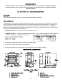
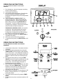
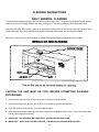
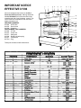
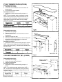
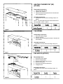
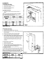
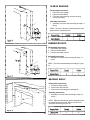
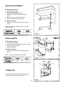
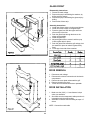
PARTS & SERVICE Manual for PANORAMA ROTISSERIE
Model SP-5
THIS MANUAL SHOULD BE RETAINED FOR FUTURE USE
0101-JDM
WARRANTY
The SP-5 Carries a 1 year warranty on parts and labor from date of unit purchase. Damage resulting from
Accident, alterations, misuse, abuse or failure to follow use and care instructions or improper installation,
Voids this warranty.
ELECTRICAL REQUIREMENTS
STOP!
Do not attempt installation until you have read the following information!
CAUTION!
This equipment is constructed of the very finest materials obtainable. In order to obtain maximum efficiency and reliability
from this equipment, please follow guidelines below concerning electrical hook-up and site preparation. In addition to its
glass and metal components, this unit contains various microprocessors and electrical components that are sensitive to
harsh environments and electrical static, spikes, voltage sags, etc., similar to any computerized device. Outlined below are
areas to be considered when performing installation.
1. DEDICATED LINE - No other equipment may be connected to this line.
2. CORRECT VOLTAGE - The voltage is specified on the data plate. This is not a dual voltage unit. Check voltage with
a meter to ascertain actual voltage (I.e. 208V or 240V).
3. SUPPLY CONNECTION WIRE GAUGE:
1 Phase – No. 8 AWG
3 Phase – No. 10 AWG
4. Never block air intake on the bottom or exhaust from left side louvers.
5. Legs must be secured and used to level the equipment.
6. No obstructions under, on top or around the unit to restrict air flow or cause unsafe conditions.
2
OPERATING INSTRUCTIONS
For Units Manufactured Before Serial Number
SP0002237
1.
2.
3.
4.
5.
6.
7.
For initial start-up, set clock for proper time of day.
(Press F while turning G)
Load rotisserie with product.
Set required cooking temperature. (Press B while
turning G) When B is released, actual oven
temperature will appear briefly until set temperature
is reached.
FOR AUTOMATIC COOKING CYCLE: Set
required cooking time. Allow approximately 20
minutes preheat time. (Press C while turning G)
Start cooking cycle by turning SELECTOR A to
“Bird symbol”. Press D to display the hour that
cooking will be completed. At that time, the buzzer
will sound and the rotisserie will shut off.
FOR MANUAL COOKING CYCLE: Set required
cooking time. Allow approximately 20 minutes
preheat time. (Press E while turning G) Start
cooking time is completed, buzzer will sound and
the rotisserie must be manually turned off.
Once cooking is completed, turn SELECTOR A to
“Jog Mode” for holding.
The buzzer can be turned off by pressing E.
To stop unit at any time, turn SELECTOR A to “Off
Mode”.
OPERATING INSTRUCTIONS
For Units Manufactured After Serial Number
SP0002236
1.
2.
3.
4.
5.
6.
7.
Load rotisserie with product. Set selector switch to
“Off Mode”.
Set required cooking temperature by turning the
TEMP ADJUST knob to the right to raise temperature or left to lower it. (The temperature setting will
appear on the right side of the display window and
will flash on and off until the oven reaches the set
point).
Set required cooking time by turning the TIME
ADJUST know to the right to increase time or to the
left to lower it. Allow approximately 20 minutes
preheat time. (The time setting will appear as
minutes and hours on the display).
Start cooking by turning selector switch to the “Bird
Symbol” and press TIMER START. (The two dots
between hours and minutes will flash on and off
when timer is running). When cooking time is
completed, buzzer will sound.
After cooking is completed, turn the selector to “Off
Mode” to stop the rotisserie, or to “Jog Mode” for
holding the product.
The buzzer can be turned off by pressing TIMER
RESET.
To stop unit at any time, turn selector switch to “Off
Mode”.
3
CLEANING INSTRUCTIONS
DAILY GENERAL CLEANING
To keep the Panorama displaying product at its best, it should be kept clean. The grease tray should be emptied and the
interior and exterior of the glass cleaned after every cooking cycle. The interior panels should be wiped with a cloth.
At the final shut-down, the drip trays, grease trays, spits and/or baskets should be removed and thoroughly washed with a
suitable detergent. The exterior metal surface should be wiped with a dampened cloth and the glass cleaned.
Be certain to clean around areas where the door gaskets make contact with the metal panels of the machine.
CAUTION: THE UNIT MUST BE COOL BEFORE ATTEMPTING CLEANING
PROCEDURES
1. Open the door and remove the 4 large nuts located in the upper cooking chamber.
2. Once the nuts have been removed, the “Air Box” will drop down for removal and cleaning.
3. Clean the grease from the “Air Box” using a suitable detergent.
4. Wipe down the temperature sensing probe which is depicted in the diagram shown above. This must be kept greasefree for proper temperature sensing.
5. IMPORTANT - AIR BOX MUST BE COMPLETELY DRY BEFORE RE-INSTALLING.
6. IMPORTANT - ONLY HAND TIGHTEN THE NUTS. THE METAL WILL EXPAND WHEN HEATED.
4
IMPORTANT NOTICE
EFFECTIVE 3/1/94
We have redesigned the controls on the SP-5
Panorama Rotisserie Oven. Starting with Serial
Number SP0002237, all of the new units will be
manufactured with a new time/temp. control/ This
control cannot be retrofitted into the units with a
display and power unit.
NEW PART NUMBERS:
#15856 - RTD Probe
#19378 - Door Switch
#19390 - Controller
DISCONTINUED PART NUMBERS:
#15250 - PT-500
#15273 - Power Unit
#15271 - Safeguard
#15269 - Display (limited supply)
#15317 - Transformer
#15794 - Peg
These part numbers will still remain active:
5
PROTECTIVE COVER (#15271)
Disassembly Instructions:
1. Disconnect main voltage.
2. Disconnect the band cable from the power section.
3. Loosen the three nuts that hold the protective cover.
4. Pull the display unit backwards.
5. Change the keyboard cover.
Assembly Instructions:
1. Assemble in reverse order according to steps 1-5
above.
NOTE: The guide pin in the keyboard cover must fit the
hole in the display unit’s timer. In order to make operation easy, push the keyboard cover underneath the
encoder knob.
DISPLAY UNIT (#15269)
Disassembly Instructions:
1. Refer to the Keyboard Cover instructions above.
POWER UNIT (#15273)
Disassembly Instructions:
1. Disconnect main voltage.
2. Disconnect all wires to the printed circuit board.
3. Carefully squeeze the four plastic distance pins that hold
the circuit card in place and pull in backwards.
Assembly Instructions:
1. Assemble in reverse order according to steps 1-3
above.
6
PT-500 THERMOCOUPLE (#15250)
Disassembly Instructions:
1. Disconnect main voltage.
2. Loosen the nut on the distance screw that holds the
thermocouple.
3. Pull the thermocouple upwards.
Assembly Instructions:
1. Assemble in reverse order according to steps 1-3
above.
NOTE: It is very important when you assemble to make
sure the thermocouple nose is inserted between the fan
wheel and “Air Box” baffle plate. Make sure the thermocouple wires do not come in contact with high voltage
conductors in the grill.
OVERHEAT PROTECTION (F1) (#15251)
Disassembly Instructions:
1. Disconnect main voltage.
2. Remove the “Air Box”.
3. Remove the hub. Refer to the instructions for motor
disassembly.
4. Remove the right inner wall.
5. Disconnect the thermostat bulb from its holder and pull it
through the wall from the electrical compartment.
6. Replace the overheat protection.
Assembly Instructions:
1. Assemble in reverse order according to steps 1-6 above.
NOTE: Make sure the distance between the bulb and the
post exceeds 14mm (9/16”). Otherwise the overheat protection will not work.
COOLING THERMOSTAT (B1) (#15252)
Disassembly Instructions:
1. Disconnect main voltage.
2. Loosen the yokes that hold the bulb.
3. Remove the thermostat.
Assembly Instruction:
1. Assemble in reverse order according to steps 1-3
above.
NOTE: The cooling thermostat should make at 140F +/50F. This should be accomplished by turning the shaft’s
D-shaped end plane so its position is perpendicular to the
long axis of the grill.
7
HEATING THERMOSTAT (B2)
(#15253)
Disassembly Instructions:
1. Disconnect main voltage.
2. Remove the “Air Box”.
3. Disconnect the thermostat bulb from its holder and
pull it through the roof.
Assembly Instructions:
1. Assemble in reverse order according to steps 1-3
above.
NOTE: The thermostat should be turned clockwise as
far as possible. (250 C – 480 F)
FAN WHEEL
Disassembly Instructions:
1. Disconnect main voltage.
2. Remove “Air Box”.
3. Remove the nut holding the fan wheel. Note the left
hand threads.
Assembly Instructions:
1. Assemble in reverse order according to steps 1-3
above.
FAN MOTOR (#15263)
Disassembly Instruc
1. Disconnect main voltage.
2. Remove the fan wheel.
3. Remove the PT-500 Thermocouple.
4. Remove the air duct.
5. Disconnect the electrical feed wires.
6. Change the fan.
Assembly Instructions:
1. Assemble in reverse order according to steps 1-6
above.
8
ELEMENTS
Disassembly Instructions:
1. Disconnect main voltage.
2. Disconnect the electrical wiring.
3. Remove the “Air Box”.
4. Disconnect the element fixture.
5. Remove the element.
Assembly Instructions:
1. Assemble in reverse order according to steps 1-5
above.
NOTE: The maximum permissible torque to be applied
when tightening the electric wire connections is 10.6 in.
lbs.. Use the double nut underneath.
GRILL MOTOR
Disassembly Instructions:
1. Disconnect main voltage.
2. Remove the nut from the center of the hub.
3. Maximum torque is 9.5 in. lbs.. Use the radial slots in the
hub for holding.
4. Remove the connector wires on the motor plate.
5. Pull the motor plate with the motor backwards.
6. NOTE: Make sure the motor shaft follows along. If not,
there is risk of losing the key between gear box shaft and
the motor shaft. In case the motor shaft does not protrude through its bearing mount, polish the part of the
shaft that protrudes through the bearing into the grill
chamber.
In case polishing is not sufficient:
1. Remove the “Air Box”.
2. Remove the right inner wall.
3. Remove the three screws holding the bearing mount.
4. The motor with its shaft and bearing mount can now be
withdrawn through the electric compartment.
Assembly Instructions:
1. Assemble in reverse order according to steps 1-5 above.
NOTE: Check the direction of rotation, which is supposed to
be counter-clockwise seen from the grill chamber side. The
bearing is self-lubricating and should not be lubricated. Check
the measurements between the bearing shelf and the hub
according to Figure 15.
9
SLEEVE BEARING
Disassembly Instructions:
1. Disconnect main voltage.
2. Remove the Grill Motor.
3. Force the journal bearing out of the bearing
mount by pressing.
Assembly Instructions:
1. Assemble in reverse order according to steps 1-3
above.
NOTE: The joint in the sleeve bearing should not be
positioned in a vertical direction.
RUBBER MOUNTS
Disassembly Instructions:
1. Disconnect main voltage.
2. Remove the Grill Motor.
3. Remove the rubber mounts.
Assembly Instructions:
1. Assemble in reverse order according to steps 1-3
above.
NOTE: The control measurements according to Figure
15.
BEARING SHELF
Disassembly Instructions:
1. Disconnect main voltage.
2. Remove the left outer wall.
3. Remove the bolt holding the bearing shelf.
Assembly Instructions:
1. Assemble in reverse order according to steps 1-3
above.
NOTE: Make sure the bearing shelf is assembled with
the milled surface horizontal. Note the control measurements according to Figure 15.
10
LEFT INNER WALL
Disassembly Instructions:
1. Disconnect main voltage.
2. Remove the Bearing Shelf.
3. Remove the “Air Box”.
Assembly Instructions:
1. Assemble in reverse order according to steps 1-3
above.
NOTE: Check the measurements according to Figure 15.
RIGHT INNER WALL
Disassembly Instructions:
1. Disconnect main voltage.
2. Remove the right inner wall. (Refer to Overheat
Protection Instructions)
Assembly Instructions:
1. Assemble in reverse order according to steps 1-2
above.
NOTE: Check the measurements according to Figure
15.
11
LOCK HANDLE
Disassembly Instructions:
1. Disconnect main voltage.
2. Remove the screws.
3. Remove the Lock Handle.
Assembly Instructions:
1. Assemble in reverse order according to steps 1-3
above.
NOTE: Use lock liquid on the screws.
LOCK CASTING
Adjusting Instructions:
1. Disconnect main voltage.
NOTE: Before adjusting the lock casting, the door
should be adjusted to 100 +/- 1mm (3.94”).
2. Loosen the screws in the casting so the casting
can be adjusted.
3. Adjust the casting so that it lines up with the
center of the hole in the handle and the vertical
measurement will be in accord with what is shown
in Figure 17.
4. Re-tighten the screws.
5. Adjust the lock wedge to make the gap between
the roof and the door roof parallel.
IR-LAMPS (#15275)
Disassembly Instructions:
1. Disconnect main voltage.
2. Remove the door roof.
3. Remove the lids over the lamps.
4. Remove the nuts on the connector cable screws.
Assembly Instructions:
1. DO NOT touch the IR-Lamps with your fingers.
2. Trim the connector strips to size.
3. Assemble in reverse order according to steps 1-4
above.
NOTE: Make sure you don’t apply torque to the
connector strip. Check to make sure the lamp is not
rigidly mounted. Remove the protective cover paper.
12
INSULATION GROMMETS
Disassembly Instructions:
1. Disconnect main voltage.
2. Remove the quartz tube.
3. Remove the electrical connections.
4. Remove the nuts that hold the IR fixtures in
place.
5. Remove the top nut from the stud screw.
6. Disassemble the insulation grommets.
Assembly instructions:
1. Assemble in reverse order according to steps 1-6
above.
NOTE: The insulation assembly should not be rigid
when assembled.
DOOR GASKETS
Disassembly Instructions:
1. Disconnect main voltage.
2. Remove the 4 pop rivets by drilling out their centers.
3. Remove the glass trim strip.
4. Remove the gasket.
Assembly Instructions:
1. Assemble in reverse order according to steps 1-4
above.
NOTE: Fill the pop rivets with silicone sealant.
POWER UNIT
This figure shows how to change between degrees
Celsius (Fig 2) instead of Fahrenheit (Fig 1).
13
GLASS FRONT
Disassembly Instructions:
1. Disconnect main voltage.
2. Remove the pop rivets holding the washers, by
drilling out their centers.
3. Remove the pop rivets holding the glass strip by
drilling.
4. Remove the silicone strip.
Assembly Instructions:
1. Install new silicone strips on both top and bottom.
2. Install new silicone strips on the glass strips.
3. Place the glass front with the upper and lower
silicone strip in the door.
4. Push the glass front through the door so the
edges are accessible.
5. Install the glass strip.
6. Adjust the glass front to center it and then pop
rivet the glass strips in place.
7. Push the glass front toward the grill and pop rivet
the washers in place to make the glass solidly
fixed.
8. Fill the pop rivets with silicone sealant.
DOOR REMOVAL
1.
2.
3.
4.
5.
Disconnect main voltage.
Disconnect the electric connections in the electric
compartment.
Remove the cover plate underneath the grill.
Remove the bolt in the pivot.
Tilt the door forward and lift the door upwards.
DOOR INSTALLATION
1.
2.
3.
Make sure the (3.94”) +/- 1mm distance is kept
when you assemble.
Also make sure the transparent cable protection is
inserted through the pivot bushing.
Assemble in reverse order according to steps 1-5
above.
NOTE: Connect the earth cable.
14
15
16
17
18
19
1111 N. Hadley Rd.
Fort Wayne, In 46804
Tel. 800-701-2992
Fax (219) 436-0735 www.mercosavory.com
20