1
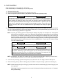
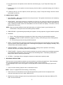
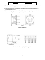
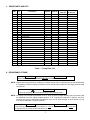
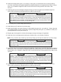
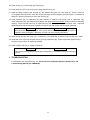
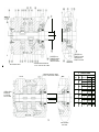
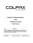
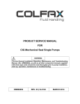
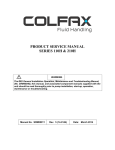
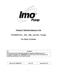
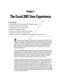
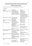
PRODUCT SERVICE MANUAL
FOR
CIG Lip Seal & Weep Hole Design
Single Pump
WARNING
The Imo General Installation Operation, Maintenance, and Troubleshooting
Manual, (No. SRM00046), as well as all other component manuals supplied
with these type units should be read thoroughly prior to pump installation,
start-up, operation, maintenance or troubleshooting.
MANUAL NO. SRM00048
REV. 03 (14-0088)
February 2014
Imo Pump
1710 Airport Road
PO Box 5020
Monroe, NC USA
28111.5020
Tel:
+1.704.289.6511
Email:[email protected]
Web: colfaxcorp.com
READ THIS ENTIRE PAGE BEFORE PROCEEDING
FOR THE SAFETY OF PERSONNEL AND TO PREVENT DAMAGE TO THE EQUIP MENT,
THE FOLLOWING NOMENCLATURE HAS BEEN USED IN THIS MANUAL:
DANGER
Failure to observe the precautions noted in this box can result in severe bodily
injury or loss of life.
WARNING
Failure to observe the precautions noted in this box can cause injury to
personnel by accidental contact with the equipment or liquids. Protection
should be provided by the user to prevent accidental contact.
CAUTION
ATTENTION
Failure to observe the precautions noted in this box can cause damage or
failure of the equipment.
Non-compliance of safety instructions identified by the following symbol could affect
safety for persons:
Safety instructions
where electrical safety
is involved are identified by:
Safety instructions which shall be
considered for reasons of safe
operation of the pump and/or protection of the pump itself are
marked by the sign:
ATTENTION
CONTENTS
SAFETY AND TABLE OF CONTENTS ................................................................................................
A.
GENERAL INSTRUCTIONS ....................................................................................................
B.
INTRODUCTION .....................................................................................................................
C.
DESCRIPTION OF EQUIPMENT ............................................................................................
D.
PUMP MODEL IDENTIFICATION ...........................................................................................
E.
ORDERING INSTRUCTIONS ...................................................................................................
F.
OPERATION ..............................................................................................................................
G.
PUMP DISASSEMBLY PROCEDURES ..................................................................................
H.
INSPECTION OF PARTS ........................................................................................................
I.
MACHINING INSTRUCTIONS ................................................................................................
J.
SPARE PARTS AND KITS .......................................................................................................
K.
PUMP REASSEMBLY PROCEDURES ..................................................................................
L.
TROUBLESHOOTING ..............................................................................................................
A
1
1
1
1
1
2
3-5
5
5-6
7
7-11
11
ATTENTION
If operation of this pump is critical to your business, we strongly recommend you
keep a spare pump or major repair kit in stock at all times. As a minimum, a minor
repair kit (O-rings, gaskets, shaft seal and bearings) should be kept in stock so
pump refurbishment after internal inspection can be accomplished.
A
A. GENERAL INSTRUCTIONS
The instructions found herein cover the disassembly, assembly and parts identification of CIG lip seal and
weep hole design single pumps.
NOTE:
Individual contracts may have specific provisions that vary from this manual. Should any questions arise
which may not be answered by these instructions, refer to the Imo General Installation Operation,
Maintenance, and Troubleshooting Manual, (No. SRM00046), provided with your order. For
further detailed information and technical assistance please refer to Imo Pump, Technical/Customer
Service Department, at (704) 289-6511.
This manual cannot possibly cover every situation connected with the installation, operation, inspection, and
maintenance of the equipment supplied. Every effort was made to prepare the text of the manual so that engineering
and design data is transformed into the most understandable wording. Imo Pump must assume the personnel assigned
to operate and maintain the supplied equipment and apply this instruction manual have sufficient technical knowledge
and are experienced to apply sound safety and operational practices which may not be otherwise covered by this
manual.
In applications where equipment furnished by Imo Pump is to become part of processing machinery, these instructions
should be thoroughly reviewed to ensure proper fit of said equipment into overall plant operational procedures.
WARNING
If installation, operation, and maintenance instructions are not correctly and strictly followed and
observed, injury to personnel or serious damage to pump could result. Imo Pump cannot accept
responsibility for unsatisfactory performance or damage resulting from failure to comply with
instructions.
B. INTRODUCTION
This instruction manual covers CIG lip seal and weep hole single pumps. This series of pumps has been designed
for use in hydraulic, lubricating seal and fuel oil applications. The model and design construction of each pump can
be identified by the designator code on the pump nameplate. Definitions of model designators are identified in Figure 1.
C. DESCRIPTION OF EQUIPMENT
The CIG lip seal and weep hole single pumps are positive displacement, internal gear pumps consisting of a single
shaft that runs through the center of pump housings. This shaft drives the external gears (pinion gears) which in
turn drives the internal gears (ring gears). Fluid is carried between the internal and external gear teeth of each pump
and is discharged as the teeth mesh. The pinion and ring gears are separated in each pump by a crescent which
is a sealing element in the pump between inlet and discharge ports.
D. PUMP MODEL IDENTIFICATION
This instruction manual covers the Imo CIG lip seal and weep hole single series pumps. The model of each pump
is identified on the pump nameplate. Refer to Figure 1 for instructional keys when using this manual.
E. ORDERING INSTRUCTIONS
When corresponding with Imo Pump regarding CIG Single Series pumps, refer to the pump nameplate, this instruction
manual, and the assembly drawing as instructed below:
1. From pump nameplate, record the pump model number. Also record the manufactured lot number and date (these
are stamped on the housing near the nameplate).
2. Record instruction manual number, revision and date.
3. From the instruction manual, record the figure numbers that apply to the replacement part(s)
4. From the assembly drawing or instruction manual (see Table 1, Pump Parts List) provides the IDP number(s) and
names for the replacement part(s).
5. Give the above information to your Imo service representative.
Imo sales and service representatives are listed herein and in General Instruction Manual, CA-1.
1
F. OPERATION
LIQUID LIMITATIONS
Never operate with fluids that are corrosive to iron, steel, aluminum or bronze. The pump is designed for fluids having
the general characteristics of oil.
CAUTION
ATTENTION
Operating conditions, such as speed, fluid viscosity, temperature, inlet pressure, discharge
pressure, filtration, duty cycle, drive type, mounting, etc. are interrelated. Due to these variable
conditions, the specific application limits may be different from that of the operational limitations.
This equipment must not be operated without verification that operating requirements are within its
capabilities.
Single Pump Model Key:
CIG
33
016
R/L I/D W/P
Series
P – Standard Viscosity Fluids
W – Low Viscosity Fluids
Frame Size
(2, 3, 4, 5, 6, 8)
I – Internal Drain
(Standard) D – External
drain For High
Suction Pressure
(Optional)
*Pressure Rating
2 = Single Stage
3 = Two Stages
4 = 3 Stages
5 = 4 Stages
6 = 5 Stages
R – CW Rotation
(Standard) L – CCW
Rotation
Nominal Displacement in CM3/Rev.
Figure 1 – Single Pump Configuration
2
G. PUMP DISASSEMBLY
Refer to Assembly 1 for one stage (X1, X2) pumps
Refer to Assembly 2 for multistage (X3, X4, X5, X6) pumps
1. Remove drive key (36)
2. Remove capscrews (38) and end cover (15) with O-ring (35).
3. Remove capscrews (39) and washers (34) (Washers not used on single stage units).
CAUTION
ATTENTION
In next step, ring gear (12), pinion (11) and key (13) will be removed. If ring (12) and pinion
(11) are to be reused, identify them, with a marker or the like, so it can be determined to
which housing they belong (if there is more than one housing in pump) and which direction
face of each gear was positioned in housing. Do not mark with scribe or punch as this may
leave a burr or high spot which could lead to pump damage or seizure. If key (13) is to be
reused, mark it so that it can be assembled into its original stage and facing its original
direction.
4. Remove square housing (4), ring gear (12), pinion gear (11) and key (13) from shaft (6). Do not permit dowel
pin (37) to drop as housing (4) is removed. Remove dowel pin (37) from square housing (4), front cover (1), or
back of round housing (3) whichever is applicable.
NOTE: If square gear housing (4) will not slide easily off shaft (6) and pump is a one stage unit, clamp square
housing (4) in a vise with front cover (1) free. With a soft headed hammer, tap alternately on mounting ears
of front cover (1) until there is sufficient gap to insert a wedging device between the square housing (4)
and front cover (1). If pump has more than one stage, clamp pump in a vise with square housing (4) free.
With a soft headed hammer, tap on corners of square housing (4) until there is sufficient gap between square
housing (4) and back of round housing (3) to insert a wedging device. Pry the gap until square housing
(4) is free to slide off shaft.
CAUTION
ATTENTION
Take care not to damage either faces that are being pried against or 0-ring (41) with prying
device.
CAUTION
ATTENTION
If gear housing (4) did not slide off easily because its bushing (53) was seized on shaft
(6), ball bearing (31) was most likely damaged when housing (4) was pried off and it must
be replaced. Alternately, if gear housing (4) will not slide off easily because its rabbet
was jammed in either front cover (1) counter bore, if single pump, or housing tube (8) if
multi-stage pump, ball bearing (31) may not have to be replaced.
NOTE: If housing (4), ring gear (12) or pinion gear (11) cannot be removed without applying excessive force,
pump should be returned to Imo for further disassembly and inspection.
5. If unit has only one stage, proceed to step #9. If pump has more than one stage, continue with step #6.
6. Remove housing tube (8). Remove O-rings (41) from rabbets on square housing (4) and round housing (3).
NOTE: Neither housing tube (8) nor O-ring (41) need be removed from round housing (3) unless O-rings (41) are
to be replaced.
(Replacing O-rings is good practice when a pump is disassembled after extended service or if damaged
during disassembly.)
3
CAUTION
ATTENTION
In next step, ring gear (12), pinion (11) and key (13) will be removed. If ring (12) and pinion (11)
are to be reused, identify them, with a marker or the like, so it can be determined to which
housing they belong (if there is more than one housing in pump) and which direction face of
each gear was positioned in housing. Do not mark with scribe or punch as this may leave a
burr or high spot which could lead to pump damage or seizure. If key (13) is to be reused,
mark it so that it can be assembled into its original stage and facing its original direction.
7. Remove round housing (3), ring gear (12), pinion gear (11) and key (13) from shaft (6). Do not permit dowel pin (37)
to drop as round housing (3) is removed. Remove dowel pin (37) from either round housing (3) or front cover (1)
whichever is applicable.
NOTE: If round gear housing (3) will not slide easily off shaft (6), and this is the last round housing (3) to be
removed, clamp it in a vice with front cover free (1). With a soft headed hammer, tap alternately on
mounting ears of front cover (1) to separate it from round housing (3). When there is sufficient gap
between front cover (1) and round housing (3), insert wedging device. Pry gap intil round housing (3) is
free to slide off shaft. If there are several round housings (3) to remove, clamp pump with a vice with
round housings (3) furthest from driver end free. Position a wedging device between the round (housings).
Pry gap until rearmost round housing (1) is free to slide off shaft (6).
CAUTION
ATTENTION
Take care not to damage either faces that are being pried against or 0-ring (41) with prying
device.
CAUTION
ATTENTION
If gear housing (3) will not slide off easily because its bushing (53) was siezed on shaft
(6), ball bearing (31) was most likely damaged when housing (3) was pried off and must
be replaced. If gear housing (3) will not slide off easily because its rabbet was jammed
in either front cover (1) counterbore, it single pump, or housing tube (8) if multi-stage pump,
ball bearing (31) may not have to be replaced.
NOTE: If housing (3), ring gear (12) or pinion gear (11) cannot be removed without applying excessive force,
unit should be returned to Imo for further disassembly and inspection.
8. Repeat steps 6 & 7 until all round housings (3) are removed.
9. Remove O-ring (41) from front cover (1) if it did not come off with last housing removed.
10. Remove capscrews (42) from seal housing (9), or (70) if "weep hole" design (see assembly drawing "inset").
11. Remove shaft (6) from front cover (1). Removal of shaft also removes seal housing (9), or (70) if "weep hole"
design, outside lip seals (32), where applicable, ball bearing (31), and bearing retaining ring (33).
CAUTION
ATTENTION
Be sure that all gear keys (13) are removed before removing shaft (6). If not, the front
cover (1) face will be damaged.
12. Remove seal housing (9), or (70) if "weep hole" design, with lip seals (32), if applicable, from shaft (6).
4
13. If lip seals (32) are to be replaced, remove them from seal housing (9), or (7) if "weep hole" design, and
discard.
14. If ball bearing (31) is to be replaced, remove snap ring (33) from shaft (1), press ball bearing (31) off shaft (1)
and discard.
15. If inside lip seal (51) is to be replaced, remove spacer (50), or (69) if "weep hole" design, and then remove
and discard lip seal (51).
H. INSPECTION OF PARTS
1. BALL BEARING – Ball bearings should be free turning and quiet. Their grease should have a soft consistency
and not look or smell burned.
2. GEAR FACES – Some light scratching is acceptable, but if there is any scoring, the part should be replaced.
These faces cannot be ground to remove a heavy score mark because their width is critical to performance of
pump. Grinding more than several ten thousandths of an inch will cause low capacity. If the face is not flat,
pump seizure could occur.
NOTE: sings are provided witRework other than light stoning or cleaning of gears or gear housings is not
recommended. New gear houh sleeve bearing factory installed.
3. RING GEAR OD – Light scratching and polishing is acceptable. If scoring is present, ring gear should be replaced.
4. HOUSING
a. Faces – Some light scratching is acceptable, but if there is any scoring, the part should be replaced.
b. Crescent – This piece should be checked for gouges or scoring. If the marking is severe, housing should
be replaced.
ID – If any scoring is present, housing should be replaced.
5. SHAFT – Check shaft for wear, particularly areas where lip seals and bushings are located when pump is assembled.
Any heavy wear is cause for shaft replacement. Check edges of keyways for cracks, chipping or rounding. If any
of these exists, shaft should be replaced.
6. SLEEVE BEARING – If scoring or heavy polishing is present, bearing must be pressed out of housing,
replaced and sized (see machining instruction on next page).
7. FRONT COVER – If faces are scored or heavily scratched, they must be machined per machining instructions.
Check ball bearing seating area in front cover after severe ball bearing failure. If ball bearing seating OD is
badly scored, deburr it before pump assembly.
8. LIP SEAL – If seal edge is flat or damaged or elastomer is deteriorated, replace lip seals.
I.
MACHINING INSTRUCTIONS
The front cover (1) can usually be restored to as-new condition by machining damaged faces. Sleeve bushings
(53), (54) and intermediate cover usually require replacement when cover is machined.
To repair damage to face of front cover (Figure 2 on next page) and to replace sleeve bushings (C) proceed as
follows:
1. Press out sleeve bushing (53)from front or intermediate covers.
NOTE: If pump is equipped with bronze bearing, consult factory.
2. Place front cover or intermediate cover in a lathe and indicate face (A) and counter bore (B) square and
concentric with respect to bore C within .0008 inch TIR.
3. Machine face (A) deep enough to remove any scored material. Ensure that face is flat within .0008 inch TIR
with a 32 micro inch finish.
5
CAUTION
ATTENTION
Being out of flat in excess of .0008" can cause pump failure.
NOTE: If more than .015" is machined (removed) from face (A, Figure 2), the same amount should be machined
removed) from G and F, Figure 2.
4. Press sleeve bushing (53) in from front cover or intermediate cover ensuring that split in bushing (53), is
positioned as shown in Figure 2.
5. Fabricate a bushing sizing tool as shown in Figure 3. Press sizing tool through bushing from same direction
bushing was originally installed to properly size bushing bore.
Figure 2 – Front Cover
Figure 3 – Sleeve Bearing (053), (054) Sizing Tool
6
J. SPARE PARTS AND KITS
*
IDP
Qty.
Description
1
3
4
6
8
9
11
12
13
15
31
32
33
34
35
36
37
38
39
41
42
50
51
53
69
70
1
−
1
1
1
1
−
−
−
1
1
2
1
4
1
1
−
4
4
−
4
1
1
−
1
1
Front Cover
Round Housing
Square Housing
Shaft
Housing Tube
Seal Housing
Pinion Gear
Ring Gear
Key
Rear Cover
Ball Bearing
Outside Seal
Bearing Snap Ring
Tie Rod Washers
Rear Cover O-Ring
Shaft Key
Housing Pin
Rear Cover Bolts
Tie Rod Bolts
Housing O-Ring
Seal Housing Bolts
Seal Spacer
Inboard Seal
Sleeve Bushing
Weep Hole Spacer
Seal Housing (Weep Hole Design)
Seal Kit
Shaft Kit
*Round Hsg. & *Square Hsg.
Gear Kit
& Gear Kit
X
X
X
X
X
X
X
X
X
X
X
X
X
X
X
X
X
Housings and gears cannot be sold separately since they are matched sets.
Table 1 – Pump Parts List
K. REASSEMBLY OF PUMP
CAUTION
ATTENTION
READ THIS ENTIRE PROCEDURE BEFORE ASSEMBLING PUMP
NOTE: Inspect all running surfaces for scratching, scoring and wear prior to assembly of pump. Minor scratching
is acceptable. If parts are heavily scratched or scored, they should be replaced. Thoroughly clean all pump
components.
WARNING
Follow the suppliers recommendations when using cleaning fluids.
NOTE: Imo Pump recommends replacement of all “O” rings, lip seals, and ball bearing every time these parts
are disturbed from their original installed position. If “O” rings and lip seals are, in general, not to be
replaced, they must be thoroughly inspected for nicks, cuts or other damage. If any individual “O” ring
or lip seal is damaged, it must be replaced.
CAUTION
ATTENTION
If ball bearing (31) was removed from shaft (6), it must be replaced. Lip seal (32) must also
be replaced (do not install lip seal until told to do so).
7
NOTE: Refer to “Inspection of Parts” for additional information on part inspection and replacement. To assist in
assembly, wipe all parts with light lubricating oil, if appropriate and available, to be pumped.
NOTE: Prior to assembly, remove all nicks and sharp edges on housings and gears with de-burring stone.
Particular attention should be paid to kidney port chamfers in housings, to faces of ring and pinion gears
and to areas of housings that were pried apart on disassembly. Avoid excessive breaking of edges at
outside diameter of ring gear as this could negatively affect flow rate. When reinstalling gears in housings,
be sure gears are installed in housings from which they were removed and face direction from which they
were removed.
Refer To Assembly 1 For One Stage (X1, X2) Pumps
Refer To Assembly 2 For Multi-Stage (X3, X4, X5, X6) Pumps
1. Press ball bearing (31) onto shaft (6), pressing only on inner race, until it contacts its mating shoulder on shaft
(6).
CAUTION
ATTENTION
Pressing bearing (31) on via its outer race will likely damage it, leading to reduced service life
or failure.
2. Install ball bearing snap ring (33) onto shaft (6).
3. Press lip seal(s), one at a time, into seal housing (9), or (70) for “weep hole” design, if applicable.
CAUTION
ATTENTION
Be sure to press only on outside diameter of lip seal(s) 32.
NOTE: Lip seal(s) (32) must be installed facing direction shown on assembly drawing.
4. Wipe small amount of grease on edges of lip seal(s) (32) for lubrication.
5. Wipe small amount of grease on edge of inside lip seal (51) and install lip seal (51) in front cover (1). Be
sure lip is facing direction shown on assembly drawing.
6. Install seal spacer (50), or (69) if “weep hole” design, into front cover. (Frame size 2 and 3 standard design
pumps do not have this spacer.) If spacer (50) is on standard design pump, it will have a counter-bore which
must be installed facing toward seal housing (9).
7. Install shaft (6) assembly with ball bearing (31) and snap ring (33) into front cover (1).
8. Install O-ring (40) onto seal housing (9) rabbet or in seal housing (70) groove, whichever is applicable.
9. Install seal housing (9), or (70) for “weep hole” design in front cover (1) and secure with capscrews (42).
Torque capscrews, with torque wrench, to torque values on assembly drawing.
10. Install first stage key (13), chamfer side up, into keyway of shaft (6) and push it up as far as possible toward
drive end of pump.
NOTE: If key (13) has a step, install key (13) with step facing up and away from front cover (1).
CAUTION
ATTENTION
When key (13) is installed and pushed up toward drive end, there must be an approximately
.020" gap between it and front cover (1) face. If not, it should be removed and a small step filed
in the portion of the keyway that sticks above shaft keyway to prevent key (13) from touching
front cover (1) face.
11. Install first stage pinion gear (11) on shaft (6). Pinion gear (11) should slide freely on shaft (6) and key (13).
If not, ensure key (13) is properly installed and shaft (6) and pinion (11) keyway are free of burrs. Ensure
pinion (11) is installed in stage from which it was removed and is facing direction from which it was
removed.
8
CAUTION
ATTENTION
If gears are installed in wrong housing, pump may not perform properly or may seize during
operation. This is because gears are matched to each housing individually and may not have
correct clearances if installed in another housing. If gears are installed facing wrong direction,
pump may not perform properly or may seize during operation. This is because some gears
have chamfers on only one side. These chamfers must be positioned facing inside of housing
so that there will be no interference with housing radii.
12. Install ring gear (12) in first stage square gear housing (4) if single stage unit, or round gear housing (3) if
multi- stage unit. Ensure ring gear (12) is installed in stage from which it was removed and is facing direction
from which it was removed if pump has more than one stage.
CAUTION
ATTENTION
If gears are installed in wrong housing, pump may not perform properly or may seize during
operation. This is because gears are matched to each housing individually and may not have
correct clearances if installed in another housing. If gears are installed facing wrong direction,
pump may not perform properly or may seize during operation. This is because some gears
have chamfers on only one side. These chamfers must be positioned facing inside of housing
so that there will be no interference with housing radii.
13. Install O-ring (41) on first stage square gear housing (4) if single stage unit, or round gear housing (3) if
multi- stage unit. Ensure ring gear (12) is installed in stage from which it was removed and is facing direction
from which it was removed if pump has more than one stage.
CAUTION
ATTENTION
If gears are installed in wrong housing, pump may not perform properly or may seize during
operation. This is because gears are matched to each housing individually and may not have
correct clearances if installed in another housing. If gears are installed facing wrong direction,
pump may not perform properly or may seize during operation. This is because some gears
have chamfers on only one side. These chamfers must be positioned facing inside of housing
so that there will be no interference with housing radii.
14. Install O-ring (41) on first stage square gear housing (4) if single stage unit, or round gear housing (3) if mutistage unit.
15 Install dowel pin (37) in front cover (1).
16. Install first stage gear round gear housing (3), or square gear housing (4) if single stage pump, with installed
ring gear (12), onto shaft (6). Ensure dowel pin (37) engages dowel pin hole in front cover (1) and pinion gear
(11) installed on shaft (6) is properly positioned to enter gear housing (3).
NOTE: If single stage pump, proceed to Step 31 to complete assembly. If multiple stage pump, continue
below with Step 16.
17. Install O-ring (41) on back of first stage gear housing (3).
18 Install housing tube (8) on back of first stage gear housing (3).
19. Install second stage key (13), chamfer side up, into keyway on shaft (6) and push it up as far as possible
toward drive end of pump.
NOTE: If key (13) has a step, install key (13) with step facing up and away from front cover (1).
CAUTION
ATTENTION
When key (13) is installed and pushed up toward drive end, there must be an approximately
.020" gap between it and front cover (1) face. If not, it should be removed and a small step filed
in the portion of the keyway that sticks above shaft keyway to prevent key (13) from touching
front cover (1) face.
9
20. Install second stage pinion gear (11) on shaft (6). Pinion gear (11) should slide freely on shaft (6) and key
(13). If not, ensure key (13) is properly installed and shaft (6) and pinion (11) keyway are free of burrs. Ensure
pinion (11) is installed in stage from which it was removed and is facing direction from which it was
removed.
21. Install ring gear (12) in second stage round gear housing (3). Ensure ring gear (12) is installed in stage from
which it was removed and is facing direction from which it was removed.
CAUTION
ATTENTION
If gears are installed in wrong housing, pump may not perform properly or may seize during
operation. This is because gears are matched to each housing individually and may not have
correct clearances if installed in another housing. If gears are installed facing wrong direction,
pump may not perform properly or may seize during operation. This is because some gears
have chamfers on only one side. These chamfers must be positioned facing inside of housing
so that there will be no interference with housing radii.
22. Install O-ring (41) on second stage gear housing (3).
23. Install dowel pin (37) back face of previous stage.
24. Install second stage round gear housing (3), with installed ring gear (12), onto shaft (6). Ensure dowel pin
(37) engages dowel pin hole in back face of previous stage and pinion gear (11) installed on shaft (6) is
properly positioned to enter gear housing (3).
25. Repeat steps 16 through 23 for third and fourth stage round gear housings (3) if applicable.
26. Install key (13) for last stage square housing (4), chamfer side up, into keyway of shaft (6).
NOTE: If key (13) has a step, install key (13) with step facing up and away from back face of previous stage.
CAUTION
ATTENTION
When key (13) is installed and pushed up toward drive end, there must be an approximately
.020" gap between it and front cover (1) face. If not, it should be removed and a small step filed
in the portion of the keyway that sticks above the shaft keyway to prevent key (13) from touching
front cover (1) face.
27. Install pinion gear (11) for square housing (4) on shaft (6). Pinion gear (11) should slide freely on shaft (6)
and key (13). If not, ensure key (13) is properly installed and shaft (6) and pinion (11) keyway are free of burrs.
Ensure pinion (11) is installed in stage from which it was removed and is facing direction from which it was
removed.
CAUTION
ATTENTION
If gears are installed in wrong housing, pump may not perform properly or may seize during
operation. This is because gears are matched to each housing individually and may not have
correct clearances if installed in another housing. If gears are installed facing wrong direction,
pump may not perform properly or may seize during operation. This is because some gears
have chamfers on only one side. These chamfers must be positioned facing inside of housing
so that there will be no interference with housing radii.
28. Install ring gear (12) in last stage square gear housing 94). Ensure ring gear (12) is installed in stage from
which it was removed and is facing direction from which it was removed.
CAUTION
ATTENTION
If gears are installed in wrong housing, pump may not perform properly or may seize during
operation. This is because gears are matched to each housing individually and may not have
correct clearances if installed in another housing. If gears are installed facing wrong direction,
pump may not perform properly or may seize during operation. This is because some gears
have chamfers on only one side. These chamfers must be positioned facing inside of housing
so that there will be no interference with housing radii.
10
29. Install O-ring (41) on last stage gear housing (4).
30. Install dowel pin (37) in back of previous stage round housing (3).
31. Install last stage (square) gear housing (4), with installed ring gear (12), onto shaft (6). Ensure dowel pin
(37) engages dowel pin hole in back face of previous stage round housing 93) and pinion gear (11) installed on
shaft (6) is properly positioned to enter gear housing (4).
32. Install washers (34) on capscrews (39) with chamfer on washers (34) facing head of capscrews (39).
Install capscrews (39), with washers (34) installed, and tighten with torque wrench to torque values on assembly
drawing. Torque one-half value for all capscrews first, then torque to full specified torque value. Capscrew
tightening pattern should be across opposite corners for both half torque and full torque tightening.
CAUTION
ATTENTION
With capscrews (30) torqued to full value, pump shaft must turn freely by hand and without
significant internal snagging. Otherwise, unit has not been properly assembled.
33. Install O-ring (35) into rear cover (15). If necessary, use a small dab of grease to hold O-ring (35) in place.
34. Install end cover (15) on square gear housing (4) using capscrews (38). Tighten capscrews (39) with torque
wrench to torque values on assembly drawing.
35. Install coupling key (36) in keyway of shaft (6).
CAUTION
ATTENTION
Take care not to bump shaft during storage, transportation, or installation of pump into operating
system.
L. TROUBLESHOOTING
For assistance with troubleshooting, see The Imo General Installation Operation, Maintenance, and
Troubleshooting Manual, (No. SRM00046).
11
4
40
"X2" TORQUE TABLE
35
FRAME
BOLT
PUMP
SIZE
SIZE
MODIFICATION
2
p
41
M12
p
60±5
81
4
M16
w
p
115±10
156
5
M20
w
p
220±15
298
M24
w
p
435±15
590
M30
w
870±25 1180
8
36
INTERNAL DRAINS SUPPLIED ON
ALL "OW" AND ''DP" PUMPS ONLY.
INTERNAL DRAINS PLUGGED ON
ALL "DW" AND "DP" PUMPS ONLY.
OUTLET
12
6
N.m
w
6
39
w
30±2
3
TORQUE BOLTS
PER PUMP SIZE
(SEE CHARn.
M10
TORQUE
LB FT
p
®
@
35
.
PUMP SIZES 2,3 & 4
TORQUE TO 12±2 LB IN
PUMP SIZES 5,6 & 8
TORQUE TO 24±2 LB IN
PUMP SIZES 2,3 & 4
TORQUE TO 12±2 LB IN
PUMP SIZES 5,6 & 8
TORQUE TO 24±2 LB IN
SEE TORQUE CHART
0
OUTLET
-INTERNAL DRAIN SUPPLIED
ON ALL "OW" AND "DP" PUMPS
"X3" TORQUE TABLE
INTERNAL DRAINS PLUGGED
ON ALL "OW" AND "DP" PUMPS
FRAME BOLT
PUMP
SIZE
SIZE MODIFICATION
2
3
EXTERNAL DRAIN
SUPPLIED ON
ALL "EW" "DW"
AND "DP': PUMPS
M16
5
M20
8
VIEW SHOWING
"042" PUMP
M12
4
6
13
M10
M24
M30
w
p
w
p
w
p
w
p
w
p
w
p
TORQUE
LB FT
30±2
45±2
60±5
90±5
115±10
175±10
220±15
325±15
N.m
41
61
81
122
156
237
298
441
435±15 590
650±20 881
870±25 1180
1300±25 1763
Imo Pump
1710 Airport Road
PO Box 5020
Monroe, NC USA
28111.5020
Tel: +1.704.289.6511
Toll: +1.877.853.7867
Email: [email protected]
e
b
:
c
© 2012 Colfax Fluid Handling all rights reserved.