1
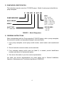
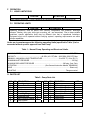
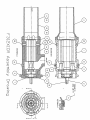
PRODUCT SERVICE MANUAL FOR
F312XICR-312_, 325_, 400_ and 437_ Pumps
For Solar Turbines
WARNING
This manual and the “General Installation, Operation, Maintenance and
Troubleshooting Manual” (SRM00046) should be read in their entirety prior to
installing, operating or servicing this pump.
Manual No SRM00105
Rev. 00
1
December 2011
READ ENTIRE PAGE BEFORE PROCEEDING
FOR SAFETY OF PERSONNEL AND TO PREVENT DAMAGE TO EQUIPMENT, THE
FOLLOWING NOMENCLATURE HAS BEEN USED IN THIS MANUAL:
DANGER
Failure to observe precautions noted in this box can result in severe bodily injury or loss of life.
WARNING
Failure to observe precautions noted in this box can cause injury to personnel by accidental
contact with the equipment or liquids. Protection should be provided by user to prevent
accidental contact.
CAUTION
ATTENTION
Failure to observe precautions noted in this box can cause damage or failure of equipment.
Non compliance of safety Safety instructions where
safety
is
instructions identified by electrical
the following symbol could involved are identified by:
affect safety for persons:
Safety instructions which shall be
considered for reasons of safe
operation of pump and/or protection of
the pump itself are marked by the sign:
ATTENTION
CONTENTS
SAFETY AND TABLE OF CONTENTS ............................................................................. 2
A. GENERAL INSTRUCTIONS ...................................................................................... 3
B. INTRODUCTION ........................................................................................................ 3
C. DESCRIPTION OF THE PUMP .................................................................................. 3
D. PUMP MODEL IDENTIFICATION ............................................................................. 4
E. ORDERING INSTRUCTIONS .................................................................................... 4
F. OPERATION .............................................................................................................. 4
G. PARTS LIST ............................................................................................................... 5
H. ASSEMBLY AND DISASSEMBLY ............................................................................. 5
I. TROUBLESHOOTING ............................................................................................... 6
J. FIELD AND FACTORY SERVICE AND PARTS .......................................................... 6
K. ASSEMBLY DRAWING ............................................................................................. 7
IMPORTANT NOTE
If operation of pump is critical to your business, we strongly recommend keeping a spare pump
or major repair kit in stock at all times. For expeditious pump refurbishment, as a minimum,
keep a minor repair kit (o-rings, gaskets, shaft seal and bearings) in stock.
2
A. GENERAL INSTRUCTIONS
Instructions found herein cover disassembly, assembly and parts identification of F312XICR
series pumps.
NOTE: Individual contracts may have specific provisions that vary from this manual. Should
any questions arise which may not be answered by these instructions, refer to
General Instructions Manual, CA-1, provided with your order. For further detailed
information and technical assistance please refer to Imo Pump, Technical/Customer
Service Department, at (704) 289-6511.
This manual cannot possibly cover every situation connected with installation, operation,
inspection, and maintenance of equipment supplied. Every effort was made to prepare
manual text so that engineering and design data is transformed into most easily understood
wording. Imo Pump must assume personnel assigned to operate and maintain supplied
equipment and apply this instruction manual have sufficient technical knowledge and are
experienced to apply sound safety and operational practices which may not be otherwise
covered by this manual.
In applications where equipment furnished by Imo Pump is to become part of processing
machinery, these instructions should be thoroughly reviewed to ensure proper fit of said
equipment into overall plant operational procedures.
WARNING
If installation, operation and maintenance instructions are not correctly and strictly followed and
observed, injury to personnel or serious damage to pump could result. Imo Pump cannot accept
responsibility for unsatisfactory performance or damage resulting from failure to comply with
instructions.
B. INTRODUCTION
This instruction manual covers F312XICR pumps. This series of pumps has been designed
for use in Lube oil applications. Model, and design construction of each pump can be
identified by designator code on pump nameplate. Definitions of model designators are
identified in Figure 1 below.
C. DESCRIPTION OF EQUIPMENT
F312XICR pumps are positive displacement, rotary screw pumps consisting of a precision
bored housing that encloses a driven screw (power rotor) and two intermeshing following
screws (idler rotors). These screws, when rotating, form a succession of closures or
cavities. As they rotate, fluid is moved axially from inlet port to outlet port in a continuous,
uniform flow with minimum fluid pulsation and pump noise.
3
D. PUMP MODEL IDENTIFICATION
This instruction manual covers Imo F312XICR pumps. Model of each pump is identified on
pump nameplate.
F 312 XIC R 437 AK
LEAD
PUMP MODIFIER
312 – 2D, CW
325D – 2D, CCW
325R – 1.6 D, CCW
400AK – 1.35D, CCW
437AK – 1.35 D, CCW
437F – 1.7D, CCW
BASIC DESIGN
SERIES
INLET TYPE
R – Axial Inlet
ROTOR SIZES
312, 325
400, 437
FIGURE 1 – Model Designators
E. ORDERING INSTRUCTIONS
When corresponding with Imo Pump regarding F312XICR pumps, refer to pump nameplate,
this instruction manual, and assembly drawing as instructed below:
1. From pump nameplate, record pump model number, serial number and manufactured
date.
2. Record instruction manual number, revision and date.
3. From assembly drawing and/or parts list (table 2) in manual, provide identification
numbers and names for replacement part(s).
4. Give above information to your Imo service representative.
Imo sales and service representatives are listed herein and in General Installation,
Operation, Maintenance and Troubleshooting Manual, SRM00046
4
F. OPERATION
F.1 LIQUID LIMITATIONS
CAUTION
ATTENTION
Never operate with water. Pump is designed for liquids having general characteristics of oil.
F.2 OPERATING LIMITS
CAUTION
ATTENTION
Operating conditions, such as speed, fluid viscosity, temperature inlet pressure, discharge
pressure, filtration, duty cycle, drive type, mounting, etc., are interrelated. Due to these variable
conditions, specific application limits may be different from that of operational limitations.
Equipment must not be operated without verifying system’s operating requirements are within
pump’s capabilities.
Under no circumstances are the following operating limits (specified in Table 1) to be
exceeded without specific approval from Imo Pump.
Table 1 – Normal Pump Operating and Structural Limits
MAXIMUM SPEED ........................................................................................................... 2250 RPM
VISCOSITY .......................................................40 SSU (4.3 CST) Min – 3000 SSU (650 CST) Max
MINIMUM – MAXIMUM LIQUID TEMPERATURE..................................... 0 to 250° F (-18 to 121°C)
MAXIMUM INLET PRESSURE .............................................................................................. 25 Psig
MAXIMUM DISCHARGE PRESSURE .............................................................. 200 psig, Cont. Duty
FILTRATION .............................................................. (See General Instruction Manual, SRM00064)
DRIVE ....................................................................................................................................Direct only
MOUNTING ............................................................................................................. Flange mounted
G. PARTS LIST
Table 2 – Pump Parts List
IDP QTY DESCRIPTION
1
2
3
4
5
6
7
8
9
1
1
2
1
1
1
1
1
6
Case/Housing
Power Rotor
Idler
Inlet head
Bearing
Retaining Ring
Retaining Ring
Inlet O-ring or Gasket
Cap Screws
KIT
IDP
X
X
X
X
10
11
12
13
14
15
20
21
X = Minor Repair Kit Items.
5
QTY DESCRIPTION
1
1
1
1
1
1
4
3
Key
Nameplate
Nameplate, Rotation
Nameplate, Suction
Nameplate, Discharge
Nameplate Drive
Pipe Plugs
Pipe Plugs
KIT
H. Assembly and Disassembly Procedures:
WARNING
Failure to observe precautions while installing, inspecting and maintaining pump can cause injury
to personnel from accidental handling of liquids that may harm skin or clothing, or fire hazard risks
from flammable liquids, or injury from high pressure fluid jets.
DANGER
BEFORE working on equipment, make sure all power to equipment is disconnected and locked-out.
H.1 GENERAL COMMENTS
NOTE: Part number identifiers contained within parenthesis such as (9) refer to circled
numbers shown on assembly drawing.
H.2 TOOLS REQUIRED
Procedures described in manual require common mechanics hand tools, a torque
wrench, dial indicator and suitable lifting device (such as) slings, straps, etc.
H.3 DISASSEMBLY PROCEDURES – See Assembly Drawing
CAUTION
Fluid leakage from disassembly of pump may make floor slippery and cause personal injury.
1. Close discharge piping to pump, disconnect piping and drain unit. Remove pump
from driver. Remove coupling key (10).
2. Remove inlet head (4) by removing capscrews (9) and then remove gasket (8).
3. Remove snap ring (6) from case/housing (1).
4. Remove power rotor (2) with bearing (5) and intermeshed idlers (3) from
case/housing (1).
CAUTION
Be sure intermeshed idlers (3) do not drop as they emerge from case/housing (1).
5. Remove bearing (5) from power rotor (2) by first removing retaining ring (7) and then
pressing bearing (5) off power rotor (2).
H.4
PUMP ASSEMBLY PROCEDURE– See Assembly Drawing
Note:
Prior to reassembly of pump, all parts should be cleaned and inspected for
nicks and burrs. Replace all worn or damaged parts. Imo Pump recommends
replacement of gasket (8), and ball bearing (5) when these parts are disturbed
from their previously installed positions. Coat all parts with light lubricating oil
to assist in assembly.
6
1. Install ball bearing (5) on power rotor (2) by pressing only on inner race of ball
bearing (5) until it seats firmly next to step in shaft (2), then install snap ring (7) in
groove on shaft (2).
2. Mesh the two idlers (3) and power rotor (2) together into a rotor assembly making
sure idler rotors (3) and balance piston are properly engaged.
3. Install rotors with installed ball bearing (5) and snap ring (6) by sliding rotor
assembly into case/housing (1) bores.
4. Install snap ring (6) in case/housing (1).
5. Install inlet (4) on case/housing (1) using bolts (9). Torque bolts to value on
assembly drawing.
6. Install coupling hub key (10) and Install and align pump and driver as specified in
“General Installation, Operation, Maintenance and Troubleshooting Manual”
(SRM00046)
I. TROUBLESHOOTING
For assistance with troubleshooting see “General Installation, Operation, Maintenance and
Troubleshooting Manual”, SRM00046.
J. FIELD AND FACTORY SERVICE AND PARTS
Imo Pump maintains a staff of trained service personnel that can provide pump installation,
pump start-up, maintenance/overhaul and troubleshooting supervision as well as installation
and maintenance training.
Our factories provide maintenance as well as overhaul and test facilities in the event user
prefers to return pumps for inspection or overhaul. Pumps that have been factoryoverhauled are normally tested and warranted “as-new” for a period of one year from date of
shipment. For either field service or factory overhaul assistance, contact your local Imo
Sales Office or representative at Technical/Customer Service Department in Monroe, NC.
USA.
Most pumps have repair kits available. Minor Repair Kits are used to repair leaking seals,
bad bearings and/or for re-assembly after pump tear-down. They include (as applicable)
pump shaft seals, packing, all gaskets/O-rings and bearings. Major Repair Kits are sufficient
to rebuild completely worn-out pumps to “as-new” condition. They include all parts found in
Minor Repair Kits plus all major internal parts subject to wear. Since kits have all necessary
parts, it is preferred that they be purchased rather than selecting individual parts. When
parts are individually selected from Parts List, some needed components are often
overlooked. In addition, mixing worn or used parts with new parts risks rapid wear and
shortened service life from new parts.
7
A Colfax Business Unit
IMO Pump
1710 Airport Road 28110
PO Box 5020
Monroe, NC/USA 28111-5020
TEL:
Email:
Web:
8
1+ (704)289-6511
[email protected]
www.imo-pump.com