1
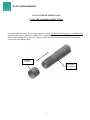
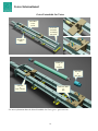
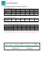
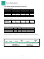
GOTCO INTERNATIONAL
SUPREME FISHING AMPLIFIER
Operation and Service Manual
1st Printing, December 19th, 2014
The design and tool specifications in this Operation & Service Manual were in effect at the time this manual was
revised and approved for printing. All information regarding tool use, design, and strength capabilities are based
on ideal conditions and are not meant to imply a guarantee, but only to be used as a reference guide. Gotco
International reserves the right to change the designs, specifications, or discontinue products without notice.
Manual No. SAM001
ISO 9001: 2008 Certified
API Spec. 7-1 Licensed
Gotco International
TABLE OF CONTENTS
(Gotco Supreme Amplifier)
General Description
2
Operations (General)
2
Preliminary Information and Rig Up Procedures
3
Jarring Procedures
3
Maintenance (After Jarring)
3
Equipment Required for Maintaining the Amplifier
3
Disassembly Procedures
4
Inspection of Parts
4
Inspection of Critical Parts
5
Pressure Body
Piston Assembly
Mandrel and Spline Body (splines)
Impact Areas & Surfaces
Assembly of the Amplifier
5
Filling the Amplifier (Silicon)
6
Testing Procedures
6-7
Test Load Chart
7
Setting Tool Instructions (for setting high pressure seals)
8
Illustration, Using the Assembly Sleeve for Assembly_________________________ 9
Extendable Jar Tester Information
10
Strength Data Charts
11-12
Specifications Chart
Strength and Test Data Chart
Recommended Tightening Torque Chart
Assembly Illustrations of “Machined Parts”
13-14
Assembly Locations of “Polypaks and Seals”
15-16
Complete Parts Lists
17-25
Amplifier Service Kit (Assembly No. and Component Part Lists)
25
Contact Information
26
LEGAL NOTICE:_______________________________________________
All references to “Logan Oil Tool” part numbers in this manual are for the sole
purpose of identifying interchangeable parts. Referencing these parts and tools
does not imply that Gotco International is in any way affiliated with Logan Oil Tools.
Gotco International does not represent any Logan Oil Tool Products.
1st Printing, December 19th, 2014
1
Gotco International
General Description:
Operation:
The Gotco Supreme Amplifier is
used in conjunction with a Gotco
Supreme Fishing Jar and it acts as a
“fluid spring” when a strain is
applied to the jarring tools in the
“fishing” string This also isolates
the kinetic energy to the area where
the energy is needed, at the point of
where the fish is stuck down-hole.
One of the primary functions of the
Supreme Amplifier is to intensify
the jarring impact that is delivered
to the stuck fish. When used with
the proper drill collars and the
Supreme Fishing Jar, it will deliver
the necessary impact to release the
stuck fish in most situations.
The Supreme Amplifier should be
placed in the string when maximum
jarring is required. This includes
when working in shallow,
directional or deviated holes. These
types of conditions and
environments tend to limit the
available “stretch” that can be
taken in the string, which limits the
effectiveness of the Supreme
Fishing Jar. The Gotco Supreme
Amplifier helps to deliver a
substantial blow the the stuck fish
by storing the energy above the
drill collars and fishing jar, to make
up for the loss of available stretch
in the string.
Once the Supreme Fishing Jar
reaches it’s Free Stroke position,
and the strain is removed from the
fishing string, the stored energy of
the Amplifier is then released,
accelerating the mass upward,
unleashing a high impact blow to
the stuck fish. The Amplifier helps
to isolate and cushion the jarring
blow and energy, to help keep the
string from rebounding, damaging
the fishing string or other tools
within the string.
The Gotco Supreme Amplifier is a
relatively easy tool to use and
requires only a straight and steady
pull, with the load determined by
the type of job in which it is being
used.
Working Load is controlled by
applying lighter or heavier pull on
the work string. Light pull will
create a light impact, and a heavy,
faster pull will create a heavy
impact.
Caution: Tong on to the Supreme
The Gotco Supreme Amplifier
should be used with the correct
Gotco Supreme Jar, having the
correct outside diameter and inside
diameters.
(See Parts List and Specifications
within this Manual for
information.)
All the internal and external
mechanically connected parts are
tightened to a recommended
tightening value. See the Charts in
the “Strength and Data Secion” of
this Manual.
Amplifier about 4 inches from the
threads on all parts. This will
prevent damage to the threaded
regions.
Caution: The Gotco Supreme
Amplifier should be located above
all the drill collars, heavy weight
drill pipe, or any other
concentrated mass, that is
immediately above the Supreme
Jar. This weight will be used to
provide the necessary impact at the
stuck point when jarring. The
working string, above the
Amplifier, should not have a weight
per foot change for at least 1,000
feet of string directly above the
Superior Amplifier. The only
2
exception is for a lighter joint
screwed directly into the Amplifier
for flexibility, when required for
“bending.” The jarring results will
be much better, if there is no
significant .weight above the
Amplifier. Excess mass or weight
above the Amplifier can cause the
impact to occur, resulting in
damage to the Amplifier, Jar,
Bottom Hole Assembly components,
or the fish being retrieved. When
working in oversized or deviated
holes, the Supreme Jar and
Amplifier should be isolated from
these areas, by using a more
flexible joint of string. This will
help to reduce damage to the
equipment and protect the tools
from fatigue failure and bending
loads.
It is recommended that not less
than two (2) joints of drill collars
and not less than four (4)
joints of heavy-wt. drill pipe be run
between the Supreme Fishing Jar
and the Supreme Amplifier, or
between the Jar and the working
string. If this can’t be avoided,
then avoid high-impact jarring
loads.
+
Gotco International
Preliminary Information:
Caution: The Gotco Supreme Amplifier
is shipped in the closed or “cocked”
position. It is installed between the
running string and the “jarring mass,”
which should be located directly above
the Gotco Supreme Fishing Jar. Once the
Amplifier is elevated in suspension, the
mandrel will open two or three inches,
prior to the Supreme Fishing Jar is
elevated.
Once the Amplifier is lowered downhole, the temperature will expand the
silicon or “energizing fluid,” and
close this gap, increasing the working
stroke of the tool.
Rig Up:
Fill the Gotco Supreme Amplifier
with the supplied, Gotco Amplifier
Fluid and test the tool as per testing
guidelines in this manual, using a
suitable test frame and tester.
Examine the Amplifier to check for
any damage parts or leakage, and to
make sure that it is properly filled.
It is recommended that not less than
two (2) joints of drill collars and not
less than four (4)
joints of heavy-wt. drill pipe be run
between the Supreme Fishing Jar and
the Supreme Amplifier, or between
the Jar and the working string. If this
can’t be avoided, then avoid highimpact jarring loads.
Jarring Procedures:
The Gotco Supreme Amplifier impact
is controlled by the amount of stretch
in the running string and the weight
of the drill collars installed above the
Supreme Fishing Jar. This is
controlled by the operator on the rig
floor. It is necessary to install the
same, similar weights (mass) above
the Amplifier, as you do the Fishing
Jar, for a minimum of 1,000 feet to
lessen the reverse inertia or kinetic
energy on the Fishing Jar and
Amplifier Assemblies. Apply the
minimum pull load above the weight
of the drill collars and running string,
to effect a sufficient blow.
Caution: Do not exceed the
published, Maximum Pull Load at
any time during the jarring
operations! See the “Strength and
Data” section of this manual.
Jarring Procedure:
1.
2.
3.
Initial blow: set the string
down to ensure the jar is
fully closed. Raise the string,
applying the desired overpull on the Jar.
Set the break and wait for
the Jar to strike a blow. This
could take a few seconds to
several minutes, depending
on certain hole conditions.
Close the Jar and repeat the
process, increasing the load
as required to free the stuck
fish.
4.
The Gotco Supreme Amplifier can
transmit full torque in left and right
hand rotation, at all times, while
maintaining full circulation through
the assembly.
After Jarring, Rig Maintenance:
Normally, no action is necessary for
Rig-down. In most cases, only minor
maintenance is required on the rig
floor. After inspecting the rig floor
for any leaks (Jar or Amplifier), lay
the Amplifier down on the derrick
floor.
Caution: The Amplifier should not
be left hanging from the elevators for
extended periods of time.
Reminder: The Gotco Supreme
Amplifier should be located above all
the drill collars, heavy weight drill
pipe, or any other concentrated mass,
that is immediately above the
Supreme Jar. This weight will be used
to provide the necessary impact at the
stuck point when jarring. The
working string, above the Amplifier,
should not have a weight per foot
3
change for at least 1,000 feet of string
directly above the Superior Amplifier.
The only exception is for a lighter
joint screwed directly into the
Amplifier for flexibility, when
required for “bending.” The jarring
results will be much better, if there is
no significant .weight above the
Amplifier. Excess mass or weight
above the Amplifier can cause the
impact to occur, resulting in damage
to the Amplifier, Jar, Bottom Hole
Assembly components, or the fish
being retrieved. When working in
oversized or deviated holes, the
Supreme Jar and Amplifier should be
isolated from these areas, by using a
more flexible joint of string. This will
help to reduce damage to the
equipment and protect the tools from
fatigue failure and bending loads.
It is recommended that not less than
two (2) joints of drill collars and not
less than four (4)
joints of heavy-wt. drill pipe be run
between the Supreme Fishing Jar and
the Supreme Amplifier, or between
the Jar and the working string. If this
can’t be avoided, then avoid highimpact jarring loads.
Immediately remove the Gotco
Supreme Amplifier from the fishing
string and flush all mud from the
internal bore, paying close attention
to mud or debris inside the Washpipe.
After Jarring Procedures:
(Dressing & Maintenance):
The Gotco Supreme Amplifier should
be disassembled, cleaned, inspected
and re-outfitted, after prolonged field
use.
Equipment Required:
1. A suitable vise and tong.
2. Over-head crane with a 1 ton
(2,000 pound) minimum lifting
capacity.
3. Pipe wrenches of various sizes for
outside diameters and internal
parts.
Gotco International
4. Chain wrenches of suitable sizes.
5. Nylon lift straps for lifting heavy
parts.
6. Suitable belt pulley assembly,
suspended from a hoist, for rotating
threaded parts during make-up or
break-out procedures.
7. Gotco Amplifier Service Kit.
8. A suitable Jar Tester to handle a
particular Jar or Amplifier length.
9. Required spare parts, and packing
sets.
10. Required “assembly sleeves” for
the tool being dressed.
Caution: The Supreme Jar could
contain residual pressure, so care
should be taken when draining oil
from the tool, to avoid bodily harm.
Disassembly Procedures:
1. Position the Gotco Supreme
Amplifier in a floor vise with the
Connector Body centered in the
vise. Support the Mandrel end of
the Jar with a support stand.
2. Loosen the Pressure Body and
back off the connection. Place a
pan beneath, to catch silicon oil in
the pressure chamber. Exercise
CAUTION at this point, due to
possible residual pressure that
could be trapped inside. Allow the
silicon oil to drain from the
Pressure Body. Do not reuse this
oil.
3. Remove the Pressure Body and
Washpipe Body as an assembly and
set it aside for disassembly later.
Support all parts with the belt
pulley, as they are being removed.
4. Unscrew and remove the Washpipe
and set it aside.
5. Remove the Piston Assembly, and
set it aside. Protect these parts by
wrapping them with cloth, bubblewrap or some other method.
6. Reposition the Amplifier in the
vise and clamp it in the vise on the
Spline Body. Support the
Amplifier at the Balance Body
location, with a support stand.
7. Remove the Connector Body and
set it aside.
Caution: The Mandrel Extension
may have ring grooves on the shaft
that could hang up on the
Connector Body I.D. seals, during
disassembly. If so, install the
“Assembly-Sleeve”(if equipped)
with the large end pointed
downward, toward the end of the
Mandrel Extension. Hold the Assy
Sleeve in position until the
Connector Body has covered the
sleeve completely. Now, the
Connector Body can be removed.
8. Remove the Assembly Sleeve
installation rings and set aside for
later use. Remove the Mandrel
Extension and set it aside on a
pallet.
9. Remove the Impact Sleeve, if
equipped with one, and set it aside.
10. Remove the Mandrel from the
Spline Body and set on a pallet.
11. Remove the Spline Body from the
Vise.
12. Position the Pressure Body and
Washpipe Body in the vise,
clamping on the Washpipe Body.
13. Remove the Pressure Body and
catch any oil that may have spilled
over into the Washpipe Body
during disassembly. Set it on a
pallet.
Disassembly has been completed.
4
Inspection of Parts:
Steam clean or high pressure wash
parts prior to inspection.
Inspect all seals and wipers and look
for unusual or suspect wear patterns.
Worn seals can cause premature seal
failure and improper performance
during jarring operations.
Note: All seals should be replaced
when doing a complete disassembly
or being repaired.
Caution: It is highly recommended
that Magnetic Particle Testing is
performed, in order to locate
fatigue cracks that can lead to tool
failure during use. Inspect all other
parts for signs of wear, especially
on the spline areas, critical I.D.
bores, bearing faces on the
connections, sealing surfaces and
impact surfaces. Check all the
shoulders on the connection joints.
Also, check for wear that was
caused by excessive torque on tools
that have been used in heavy
torsional operations, such as
milling jobs.
**See the following pages for
Inspection of Critical Parts.
Gotco International
Inspection of Critical Parts:
Assembly Procedures:
Piston Assembly:
Inspect the Piston (Adapters, Packing
Sets, Pressure Ring, Copper Rings)
cracking or imperfections.
Preparation:
Pressure Body:
Examine the finished, I.D. bore for
galling and pitting. If there appears to
be any significant damage, the parts
will need to be replaced or possibly
reworked with chrome plating and
grinding. This will need to be done
by the manufacturing facility of
Gotco International.
Spline Body:
All of the splines inside the Spline
Body need to be checked for damage
such as heavy wear, burrs or rounded
edges. Remove burrs with a file or
grinder. Also check the “Impact
Sleeve” large end face, if equipped.
Mandrel:
All of the splines on the Mandrel
need to be checked for damage such
as heavy wear, burrs or rounded
edges. Remove burrs with a file or
grinder.
Caution: Wear protective eyewear
and gloves when using power tools
for removing burrs from the spline
areas.
Impact Surfaces:
Impact loads occur mainly on the
male end of the Spline Body and the
Impact Sleeve, on the large O.D. end.
(If equipped with an Impact Sleeve.)
These areas need to be inspected for
imperfections caused by high impact
loads. Any upset can be removed
with a file or hand, die grinder, using
the proper bit. Also check for visual
signs of cracking or any other
damage.
(SEE SETTING TOOL
INSTRUCTIONS, AT THE END OF
THIS SECTION))
Clean and inspect all parts, prior to
assembly.
Install all the seals and wipers in their
proper location, paying close
attention to orientation of these parts.
All of the seals should be coated with
silicon oil, prior to assembly.
(See the Illustrations in this Manual)
1. Place the Spline Body in the vise
and clamp it down securely. Apply
anti-galling grease to the inside of
the splines and at the top end of the
Spline Body, past the seal gland
areas.
2. Install the Mandrel through the
Spline Body. Ensure the splines on
the Mandrel or properly aligned
with the splines on the Spline
Body. Grease the splines on the
Mandrel first.
3. Install the Mandrel Extension onto
the end of the Mandrel and torque
it to the specified value, as shown
in the Strength Data Charts in this
manual.
Note: Some Jars require a Jar
Impact Sleeve. If your assembly
does, then install it before the
Mandrel Extension is screwed onto
the Mandrel. Install the sleeve with
the larger O.D. going on first.
Make sure the threads are coated
with a suitable, high-quality thread
compound. Keep the thread
compound between the O-ring seals
on the connection, to avoid
contaminating the hydraulic oil.
4. Install the Balance Body onto the
Spline Body. The balance holes
should be pointed away from the
Spline Body. Coat the threads with
thread compound.
5
Use the Mandrel Assembly
Sleeve or split rings on/ or in the
Mandrel Extension grooves, or
shoulder area. (See Page 9) Install
the split rings or Mandrel
Assembly Sleeve with the largest
O.D. end toward the Balance Body.
5. Install the Connector Body over
the Mandrel Extension, with the
I.D. Wiper end, pointed upward,
toward the Balance Body.
Lubricate the length of the Mandrel
Extension with silicon oil, for
easier assembly. Screw the
threaded end into the Balance Body
and tighten. ** Remove the
“Installation Sleeve or split rings”
from the grooves on the Mandrel
Extension.
6. Install the Packing Assembly on
the Mandrel Extension.
7. Screw on the Washpipe to the
Mandrel Extension. Apply thread
compound to the threads of the
Mandrel Extension. Torque to the
values given in the “Strength and
Data Chart” in this Manual.
8. Install the Pressure Body.
Note: The Pressure Body is stenciled
or marked with “Connector Body
End” and “Washpipe Body End,”
as to avoid confusion. Please
assemble in the proper direction.
Use a high quality thread
compound on the Connector Body
threads, prior to assembly.
9. Install the Washpipe Body. Coat
threads with thread compound.
15. Tighten all the external part joints
to the recommended tightening
torque specified. See the Strength
and Data Tables, Chart “C,” in
this manual.
(Continues on the next page)
Gotco International
Filling & Testing the Supreme
Amplifer:
Note: The Gotco Supreme Amplifier
should be only filled with
Amplifier Fluid (special silicon.)
Note: If the pull load needs to be
adjusted, make the adjustment
and then remove the tension
from the amplifier, then re-pull
the tool again, to insure an
accurate pull-load pressure
reading on the test unit.
1. Stroke the Mandrel, so the gap is in
the filled position, see Test Load
Chart on the following page.
2. With the test load applied, measure
the Pull Stroke Length. (Reference
the Chart in this section.)
2. With the tool horizontal, rotate the
tool so that the fill plug ports in the
Connector Body are pointing
straight up and down.
3. If the Pull stroke is not correct,
then apply a strain (pull), hold for a
short time, then relax the strain.
Repeat this several times to
properly set the packing, prior to
adjusting the fluid level.
3. Tilt the Amplifier 15-20 degrees
from horizontal, Mandrel end
highest.
4. Fill the fluid chamber with Gotco
Silicon Oil, using the ports on the
Connector Body, until all the air is
removed. Pump the fluid in the fill
plug port on the underside of the
tool, allowing air and oil to escape
from the fill plug port on the topside of the tool, returning to the
pump reservoir. When all the air
has been removed, install the fill
plugs in both ports.
Testing the Supreme Amplifier:
1. Set the “jar tester” to the “Test Pull
Load” chart in this manual.
Perform this test inside the “jar
tester.”
4. If the Pull Stroke Length is short,
then the tool has too much fluid
and some will need to be
removed.
Caution: Use caution when
removing the fill plug, because
residual pressure can still be
inside the tool. Before removing
the fill plug, use the Jar Tester to
push the tool closed all the way.
**Only the top fill plug needs to be
removed to drain some of the
fluid. Only a very small amount of
fluid should be removed at a time.
Then, retest to tool to see the
results, and repeat this process
until the proper Test Pull Load is
achieved, as shown in the Charts.
6
5. If the Pull Stroke Length is long,
then the tool has too little fluid and
some will need to be added.
**Only the top fill plug needs to be
removed to add some of the fluid.
Only a very small amount of fluid
should be added at a time. Then,
retest to tool to see the results, and
repeat this process until the proper
Test Pull Load is achieved, as
shown in the Charts.
6. The Gotco Supreme Amplifier is
properly filled when the Test Pull
Load is reached, and has reached
the Pull Stroke Length, (+-) 1/8”.
7. Relieve the strain on the jar tester,
allowing the amplifier to retract as
far as it will go, without the aid of
the jar tester pushing it. Measure
the “Release Position,” and
compare it to the data in the
provided Chart in this section.
The gap should be within about
1/4 inch of the given values.
SEE “TEST LOAD CHART”
On the following page.
Gotco International
TEST LOAD CHART
Measure Fill Position
Measure Pull Stroke Length
Measure Release Position
GOTCO
NO.
REF.
NO.
Tool Size
(OD x ID)
Connection
Fill
Position
Test Pull
Load
Test Pull
Stroke
Release
Position
Total
Stroke
Torque
(ft.-lbs.)
SA-306
614-306
3-1/16” x 1-1/2”
2-3/8 EUE
2-1/2”
30,500
5-7/8”
3-11/16”
6”
2,400
SA-31
614-312
3-1/8” x 1”
2-3/8 REG
2”
43,692
5-7/8”
4”
6”
2,700
SA-313
614-313
3-1/8” x 1-1/2”
2-7/8 PAC
2-1/2”
28,450
5-3/4”
3-1/2”
6”
2,600
SA-377
614-377
3-3/4” x 1-1/4”
2-7/8 REG
2-1/2”
56,900
6-3/8”
3-7/8”
6-5/8”
3,500
SA-36
614-375
3-3/4” x 1-1/2”
2-3/8 IF
2-1/2”
56,900
6-3/8”
3-3/8”
6-5/8”
3,500
SA-42
614-425
4-1/4” x 2”
2-7/8 IF
2-1/4”
40,600
5-11/16”
4”
6-3/16”
5,000
SA-46
614-475
4-3/4” x 2-1/4”
3-1/2 IF
3-1/4”
81,300
6-5/8”
4-1/8”
7”
9,000
SA-62
614-625
6-1/4” x 2-1/4”
4-1/2 IF
3-1/2”
121,900
7-11/16”
4-9/16”
8-3/16”
20,000
SA-76
614-775
7-3/4” x 3-1/16”
6-5/8 REG
3-5/8”
126,000
7”
4-1/2”
8-1/2”
39,000
7
Gotco International
GOTCO SUPREME AMPLIFIER
SETTING TOOL INSTRUCTIONS:
It is recommended that you use the proper “Setting Tool,” when installing the Copper Non-Extrusion Rings,
Protector Rings and O-ring Seals in the high-pressure sealing areas. This is normally in the Connector Body
and Seal Body parts. The illustration below represents either of these locations and the technique is the
same for any area on the Supreme Fishing Jar or the Supreme Amplifier assemblies.
This is the part containing the high pressure
copper rings and seals. This can be the
Connector Body, Seal Body, etc. It should be
positioned with the high-pressure ring end
facing upward.
Stand the part on end, with rings facing
up. Insert the setting tool, by lowering
into the cavity. Lightly drive it in with a
sledge hammer, tapping around on the
striking end of the tool.
This is the typical arrangement of
the high pressure seal areas, having
an O-ring, Seal Protector Ring and a
Non-Extrusion Ring
8
Gotco International
GOTCO SUPREME FISHING JARS
USING THE ASSEMBLY SLEEVE TOOL:
Use the Mandrel Assembly Sleeve or split rings on/ or in the Mandrel Extension grooves, or shoulder area.
Install the split rings or Mandrel Assembly Sleeve with the largest O.D. end toward the Balance Body.
Remove the assembly sleeve, once the Connector Body has been slid over the Mandrel Extension and
screwed on to the Balance Body.
ASSEMBLY
SLEEVE
MANDREL
EXTENSION
9
Gotco International
Gotco Extendable Jar Tester
Extendable
Tester
Frame
Removable
End Plate
for Adding
Extension
Hold Down
Pads
Fishing Jar
or
Amplifier
Test Subs
at
Each End
Pull Plate
&
Hyd. Cylinder
Stationary Plate
&
Pins
For more information about the Gotco Extendable Jar Tester, go to “gotco-usa.com”
10
Gotco International
Gotco Supreme Amplifier Strength and Testing Data
CHART “A” - SPECIFICATIONS
COMPETE ASSEMBLY
SA-306
3-1/16
O.D (ins)
1-1/2
I.D (ins)
2-3/8 API EUE
Connection
12’ - 4”
Length (ft. & ins)
6
Stroke (ins)
300 – 4,000
Drill Collar Weight Range
(lbs.)
3
Pump Open Area (sq. ins)
SA-31
3-1/8
1
2-3/8 API REG
8’ - 6”
6
300 – 4,000
SA-313
3-1/8
1-1/2
2-7/8 PAC
12’ - 4”
6
300 – 4,000
SA-36
3-3/4
1-1/2
2-3/8 API IF
11’ – 10-1/2”
10
400 – 6,000
SA-377
3-3/4
1-1/4
2-7/8 API REG
11’ – 10-1/2”
xx
400 – 6,000
SA-376
3-3/4
1-7/8
2-3/8 API EUE
11’ – 10-1/2”
xx
400 – 6,000
3
3
4
4
4
SA-313
185,000
SA-36
330,000
SA-377
330,000
SA-376
285,000
4,200
14,500
14,500
9,650
CHART “B” – STRENGTH AND TEST DATA
COMPETE ASSEMBLY
SA-306
SA-31
185,000
253,000
Lift Load after Jarring
Jar Fully Extended
Tensile @ Yield (lbs.)
4,200
7,500
Torque @ Yield (ft.-lbs.)
CHART “C” – RECOMMENDED TIGHTENING TORQUES (ft.-lbs.)
COMPETE ASSEMBLY
SA-306
SA-31
2,100
2,700
Spline Body to Balance Body
500
600
Mandrel to Mandrel Extension
2,100
2,700
Balance Body to Connector Body
2,100
2,700
Connector Body to Pressure Body
500
600
Mandrel Extension to Washpipe
2,100
2,700
Pressure Body to Washpipe Body
(xx = contact GOTCO Engineering for details)
SA-313
2,100
500
2,100
2,100
500
2,100
SA-36
3,500
700
3,500
3,500
700
3,500
SA-377
3,650
700
3,650
3,650
700
3,650
SA-376
3,500
700
3,500
3,500
700
3,500
These values represent the maximum allowable makeup torque values for these connections. Torque values this high are not always required for each
every fishing job and lower values should be considered to save wear on the threads. A good thread compound should be used on these connections.
11
Gotco International
Gotco Supreme Amplifier Strength and Testing Data
CHART “A” - SPECIFICATIONS
COMPETE ASSEMBLY
SA-42
4-1/4
O.D (ins)
2
I.D (ins)
2-7/8 API IF
Connection
11’ – 4”
Length (ft. & ins)
6-3/8
Stroke (ins)
400 - 6,000
Drill Collar Weight Range
(lbs.)
6
Pump Open Area (sq. ins)
SA-44
4-1/2
2-3/8
2-7/8 API EUE
xx
xx
400 – 6,000
SA-46
4-3/4
2-1/4
3-1/2 API IF
11’ – 6”
7
500 – 8,000
SA-62
6-1/4
2-1/4
4-1/2 API IF
13’ – 8”
8-3/16
8,500 – 15,000
SA-76
7-3/4
3-1/16
6-5/8 API REG
15’ – 7”
8-1/2
12,200 – 21,000
7-1/2
7
11
16
SA-46
505,000
SA-62
1,000,000
SA-76
1,600,000
18,100
40,800
79,000
CHART “B” – STRENGTH AND TEST DATA
COMPETE ASSEMBLY
SA-42
SA-44
375,000
360,000
Lift Load after Jarring
Jar Fully Extended
Tensile @ Yield (lbs.)
18,500
12,000
Torque @ Yield (ft.-lbs.)
CHART “C” – RECOMMENDED TIGHTENING TORQUES (ft.-lbs.)
COMPETE ASSEMBLY
SA-42
SA-44
5,000
3,500
Spline Body to Balance Body
1,500
700
Mandrel to Mandrel Extension
5,000
3,500
Balance Body to Connector Body
5,000
3,500
Connector Body to Pressure Body
1,500
700
Mandrel Extension to Washpipe
5,000
3,500
Pressure Body to Washpipe Body
(xx = contact GOTCO Engineering for details)
SA-46
9,090
1,800
9,090
9,090
1,000
9,090
SA-62
20,000
7,000
20,000
20,000
4,800
20,000
SA-76
39,000
12,500
39,000
39,000
10,500
39,000
These values represent the maximum allowable makeup torque values for these connections. Torque values this high are not always required for each
every fishing job and lower values should be considered to save wear on the threads. A good thread compound should be used on these connections.
12
Gotco International
METAL PARTS
(UPPER HALF)
13
Gotco International
METAL PARTS
(LOWER HALF)
14
Gotco International
POLYPAKS & SEALS
(UPPER HALF)
15
Gotco International
POLYPAKS & SEALS
(LOWER HALF)
16
Gotco International
SUPREME AMPLIFIERS
SIZE
CONNECTIONS
OUTSIDE DIA.
INSIDE DIAM.
COMPLETE
ASSEMBLY
INCHES
INCHES
PART#
XREF#
2-3/8
EUE
3-1/16
1-1/2
SA-306
614-306
2-3/8
API REG
3-1/8
1
SA-31
614-312
2-7/8
PAC
3-1/8
1—1/2
SA-313
614-313
2-3/8
I.F.
3-3/4
1-1/2
SA-36
614-375
2-7/8
API REG
3-3/4
1-1/4
SA-377
614-377
2-3/8
EUE
3-3/4
1-7/8
SA-376
614-376
MAJOR COMPONENT PARTS
MANDREL
MANDREL
EXTENSION
MANDREL
IMPACT
SLEEVE
SPLINE BODY
BALANCE
BODY
PISTON ASSY
CONSIST OF:
PACKING SET
MALE
ADAPTER
SPACER RING
WASHPIPE
BODY
WASHPIPE
CONNECTOR
BODY
PRESSURE
BODY
SETTING TOOL
CONN. BODY
I.D.
MANDREL EXT.
ASSEMBLY
SLEEVE
PART#
XREF#
PART#
XREF#
PART#
XREF#
SA-306-2
BX11
SA-306-2X
BX51
SA-313-2-IS
BX31
SA-31-2
BX10
SA-31-2X
BX50
SA-31-2-IS
BX30
SA-313-2
BX11
SA-313-2X
BX51
SA-313-2-IS
BX31
SA-36-2
BX12
SA-36-2X
BX52
…..
…..
SA-377-2
(BX12)
SA-377-2X
(BX52)
……
…..
SA-376-2
BX18
SA-376-2X
BX58
SA-376-IS
BX38
PART#
XREF#
PART#
XREF#
SA-313-4
BX21
SA-313-5
BX41
SA-31-4
BX20
SA-31-5
BX40
SA-313-4
BX21
SA-313-5
BX41
SA-36-4
BX22
SA-36-5
BX42
SA-36-4
(BX22)
SA-36-5
(BX42)
SA-376-4
BX28
SA-376-5
BX48
PART#
XREF#
SA-313-3
BX61
SA-31-3
BX60
SA-313-3
BX61
SA-36-3
BX62
SA-36-3
(BX62)
SA-376-3
BX68
PART#
XREF#
PART#
XREF#
PART#
XREF#
SA-313-3-4
BX61-1
SA-313-3-2M
BX61-2
SA-313-3-3
BX61-3
SA-31-3-4
BX60-1
SA-31-3-2M
BX60-2
SA-31-3-3
BX60-3
SA-313-3-4
BX61-1
SA-313-3-2M
BX61-2
SA-313-3-3
BX61-3
SA-36-3-4
BX62-1
SA-36-3-2M
BX62-2
SA-36-3-3
BX62-3
SA-36-3-4
(BX62-1)
SA-36-3-2M
(BX62-2)
SA-36-3-3
(BX62-3)
SA-376-3-4
BX68-1
SA-376-3-2M
BX68-2
SA-376-3-3
BX68-3
PART#
XREF#
PART#
XREF#
PART#
XREF#
PART#
XREF#
PART#
XREF#
SA-306-6
BX111
SA-306-8
BX101
SA-313-9
BX71
SA-313-10
BX91
SA-313-17
SA-31-6
BX110
SA-31-8
BX100
SA-31-9
BX70
SA-31-10
BX90
SA-31-17
SA-313-6
BX111
SA-313-8
BX101
SA-313-9
BX71
SA-313-10
BX91
SA-313-17
SA-36-6
BX112
SA-36-8
BX102
SA-36-9
BX72
SA-36-10
BX92
SA-36-17
SA-377-6
(BX112)
SA-377-8
(BX102)
SA-36-9
(BX72)
SA-36-10
(BX92)
SA-36-17
SA-376-6
BX118
SA-376-8
BX108
SA-376-9
BX78
SA-376-10
BX98
SA-376-17
PART#
XREF#
SA-313-SLV
BD205-6
SA-31-SLV
BX140-5
SA-313-SLV
BD205-6
SA-36-SLV
BX201-6
SA-36-SLV
(BX201-6)
SA-376-SLV
BD208-6
**Setting Tools are Optional Equipment.
* See Ordering Instructions in this Section.
17
Gotco International
SUPREME AMPLIFIERS
SIZE
CONNECTIONS
OUTSIDE DIA.
INSIDE DIAM.
COMPLETE
ASSEMBLY
INCHES
INCHES
PART#
XREF#
2-7/8
API I.F.
4-1/4
2
SA-42
614-425
3-1/2
API I.F.
4-3/4
2-1/4
SA-46
614-475
4-1/2
API I.F.
6-1/4
2-1/4
SA-62
614-625
5-1/2
API REG
6-3/4
2-3/4
SA-66
614-675
5-1/2
API REG
7-3/4
3-1/16
SA-76
614-775
MAJOR COMPONENT PARTS
MANDREL
MANDREL
EXTENSION
MANDREL
IMPACT
SLEEVE
SPLINE BODY
BALANCE
BODY
PISTON ASSY
CONSISTS OF:
PACKING SET
MALE
ADAPTER
SPACER RING
WASHPIPE
BODY
WASHPIPE
CONNECTOR
BODY
PRESSURE
BODY
SETTING TOOL
CONN. BODY
I.D.
MANDREL EXT.
ASSEMBLY
SLEEVE
PART#
XREF#
PART#
XREF#
PART#
XREF#
SA-42-2
BX13
SA-42-2X
BX53
……
…….
SA-46-2
BX14
SA-46-2X
BX54
SA-46-2-IS
BX34
SA-62-2
BX15
SA-62-2X
BX55
…..
…..
SA-66-2
BX16
SA-66-2X
BX56
SA-66-2-IS
BX36
SA-76-2
BX17
SA-76-2X
BX57
SA-76-IS
BX37
PART#
XREF#
PART#
XREF#
SA-42-4
BX23
SA-42-5
BX43
SA-46-4
BX24
SA-46-5
BX44
SA-62-4
BX25
SA-62-5
BX45
SA-66-4
BX26
SA-66-5
BX46
SA-76-4
BX27
SA-76-5
BX47
PART#
XREF#
SA-42-3
BX63
SA-46-3
BX64
SA-62-3
BX65
SA-66-3
BX66
SA-76-3
BX67
PART#
XREF#
PART#
XREF#
PART#
XREF#
SA-42-3-4
BX63-1
SA-42-3-2M
BX63-2
SA-42-3-3
BX63-3
SA-46-3-4
BX64-1
SA-46-3-2M
BX64-2
SA-46-3-3
BX64-3
SA-62-3-4
BX65-1
SA-62-3-2M
BX65-2
SA-62-3-3
BX65-3
SA-66-3-4
BX66-1
SA-66-3-2M
BX66-2
SA-66-3-3
BX66-3
SA-76-3-4
BX67-1
SA-76-3-2M
BX67-2
SA-76-3-3
BX67-3
PART#
XREF#
PART#
XREF#
PART#
XREF#
PART#
XREF#
PART#
XREF#
SA-42-6
BX113
SA-42-8
BX103
SA-42-9
BX73
SA-42-10
BX93
SA-42-17
SA-46-6
BX114
SA-46-8
BX104
SA-46-9
BD62
SA-46-10
BX94
SA-46-17
SA-62-6
BX115
SA-62-8
BX105
SA-62-9
BD63
SA-62-10
BX95
SA-62-17
SA-66-6
BX116
SA-66-8
BX106
SA-66-9
BD67
SA-66-10
BX96
SA-66-17
SA-76-6
BX117
SA-76-8
BX107
SA-76-9
BD64
SA-76-10
BX97
SA-76-17
PART#
XREF#
SA-42-SLV
BD206-6
SA-46-SLV
BX144-5
SA-62-SLV
BX145-5
……
…….
……
……
**Setting Tools are Optional Equipment.
* See Ordering Instructions in this Section.
18
Gotco International
SUPREME AMPLIFIERS
SIZE
CONNECTIONS
OUTSIDE DIA.
INSIDE DIAM.
COMPLETE
ASSEMBLY
INCHES
INCHES
PART#
XREF#
2-3/8
EUE
3-1/16
1-1/2
SA-306
614-306
2-3/8
API REG
3-1/8
1
SA-31
614-312
2-7/8
PAC
3-1/8
1—1/2
SA-313
614-313
2-3/8
I.F.
3-3/4
1-1/2
SA-36
614-375
2-7/8
API REG
3-3/4
1-1/4
SA-377
614-377
2-3/8
EUE
3-3/4
1-7/8
SA-376
614-376
O-RINGS, WIPERS, AND PARBAK RINGS
G-2-225
568-225 (1)
……
……
G-2-225
568-225 (1)
……
……
G-2-230
568230 (1)
G-2-230
568230 (2)
G-2-228
568228 (2)
……
……
G-8-228
8-228 (2)
G-2-005
568005
(2)
……
……
…….
G-2-230
568230 (1)
G-2-230
568230 (2)
G-2-228
568228 (2)
……
……
G-8-227
8-227 (2)
G-2-006
568006
(2)
……
…….
……
……
G-2-230
568230 (1)
G-2-230
568230 (2)
G-2-228
568228 (2)
……
……
G-8-228
8-228 (2)
G-2-005
568005
(2)
…….
……
PART#
XREF#
PART#
XREF#
PART#
XREF#
PART#
XREF#
……
……
G-2-224
568224 (1)
G-2-230
568230 (1)
G-2-228
568228 (1)
G-2-130
568130 (1)
G-2-221
568221 (1)
G-2-230
568230 (1)
G-2-228
568228 (1)
PART#
XREF#
SA-306-20
BX131
SA-31-20
BX130
MANDREL
SEAL
MANDREL EXT.
SEAL
MANDREL EXT.
WIPER
SPLINE BODY
SEAL
CONN. BODY
SEAL –(LARGE)
CONN. BODY
SEAL – (SMALL)
CONN BODY
WIPER
CON BODY
PARBAK RING
CONN BODY
FILL PLUG
SEAL
PRESSURE
BODY
FILL PLUG
SEALWASHPIPE
SEAL-(LARGE)
WASHPIPE
SEAL-(SMALL)
W’PIPE BODY
SEAL- (LARGE).
W’PIPE BODY
SEAL-(SMALL)
PART#
XREF#
PART#
XREF#
PART#
XREF#
PART#
XREF#
PART#
XREF#
PART#
XREF#
PART#
XREF#
O-RING
PACKING SET
PART#
XREF#
PART#
XREF#
…..
…..
G-2-225
568225 (1)
……
……
……
……
G-2-234
568234 (1)
G-2-234
568234 (2)
G-2-232
568232 (1)
SJ-36-9W
BD71 (1)
G-2-225
568225 (1)
……
……
……
…...
G-2-234
568234 (1)
G-2-234
568234 (2)
G-2-232
568232 (1)
SJ-36-9W
BD71 (1)
……
……
…..
……)
……
……
……
……
……
…..
G-2-006
568006
(2)
……
……
G-2-006
568006
(2)
……
…….
…..
……
……
……
……
……
……
G-2-224
568224 (1)
G-2-230
568230 (1)
G-2-228
568228 (1)
G-2-227
568227 (1)
G-2-225
568225 (1)
G-2-234
568234 (1)
G-2-232
568232 (1)
G-2-227
568227 (1)
G-2-225
568225 (1)
G-2-234
568234 (1)
G-2-232
568232 (1)
……
……
……
……
……
……
……
……
SA-313-20
BX131
SA-36-20
BX132
SA-36-20
BX132
SA-376-20
BX138
* See Ordering Instructions in this Section.
* WIPERS ARE NOT PART OF THE “O-RING PACKING SET.”
19
Gotco International
SUPREME AMPLIFIERS
SIZE
CONNECTIONS
OUTSIDE DIA.
INSIDE DIAM.
COMPLETE
ASSEMBLY
INCHES
INCHES
PART#
XREF#
2-7/8
API I.F.
4-1/4
2
SA-42
614-425
3-1/2
API I.F.
4-3/4
2-1/4
SA-46
614-475
4-1/2
API I.F.
6-1/4
2-1/4
SA-62
614-625
5-1/2
API REG
6-3/4
2-3/4
SA-66
614-675
5-1/2
API REG
7-3/4
3-1/16
SA-76
614-775
O-RINGS, WIPERS, AND PARBAK RINGS
MANDREL
SEAL
MANDREL EXT.
SEAL
MANDREL EXT.
WIPER
SPLINE BODY
SEAL
CONN. BODY
SEAL –(LARGE)
CONN. BODY
SEAL – (SMALL)
CONN BODY
WIPER
CONN BODY
PARBAK RING
CONN BODY
FILL PLUG
SEAL
PRESSURE
BODY
FILL PLUG
SEAL
SEAL BODY
SEALWASHPIPE
SEAL-(LARGE)
WASHPIPE
SEAL-(SMALL)
W’PIPE BODY
SEAL- (LARGE).
W’PIPE BODY
SEAL-(SMALL)
O-RING
PACKING SET
G-2-236
568236 (1)
……
……
……
……
……
PART#
XREF#
PART#
XREF#
PART#
XREF#
PART#
XREF#
PART#
XREF#
PART#
XREF#
PART#
XREF#
G-2-229
568229 (1)
……
……
……
G-2-232
568232 (1)
……
……
……
G-2-238
568238 (1)
G-2-238
568238 (2)
G-2-236
568236
SJ-42-9W
BD76 (1)
G-2-242
568242 (1)
G-2-242
568242 (2)
G-2-239
568239 (1)
SA-46-9W
BX84 (1)
SJ-62-2X-W
BD223
G-2-254
568254 (1)
G-2-253
568253 (2)
G-2-250
568250 (1)
SJ-62-9W
BD73 (1)
PART#
XREF#
G-2-006
568006
G-2-005
568005 (1)
G-2-006
568006
(2)
G-2-005
568005 (1)
……
……
PART#
XREF#
G-2-006
568006
(2)
G-2-005
568005 (1)
……
……
G-2-006
568006
(2)
G-2-005
568005 (1)
PART#
XREF#
PART#
XREF#
PART#
XREF#
PART#
XREF#
PART#
XREF#
PART#
XREF#
G-2-231
568231 (1)
G-2-231
568231 (1)
G-2-229
568229 (1)
G-2-238
568238 (1)
G-2-236
568236 (1)
SA-42-20
BX133
G-2-234
568234 (1)
G-2-234
568234 (1)
G-2-232
5682232 (1)
G-2-242
568242 (1)
G-2-239
568239 (1)
SA-46-20
BX134
G-2-341
568341 (1)
G-2-238
568238 (1)
G-2-234
568234
G-2-252
568252 (1)
G-2-250
568250 (1)
SA-62-20
BX135
…….
…….
……
……
……
……
……
……
……
……
SA-66-20
BX136
G-2-347
568347 (1)
G-2-347
568347 (1)
……
……
G-2-362
568362 (1)
G-2-361
568361 (1)
SA-76-20
BX137
……
……
……
……
……
……
SA-66-9W
BX86 (1)
* See Ordering Instructions in this Section.
* WIPERS ARE NOT PART OF THE “O-RING PACKING SET.”
20
G-2-348
568348 (1)
SJ-76-2X-W
BD224
G-2-362
568362 (1)
G-2-362
568362 (2)
G-2-361
568361 (1)
SJ-76-9W
BD74 (1)
Gotco International
SUPREME AMPLIFIERS
SIZE
CONNECTIONS
OUTSIDE DIA.
INSIDE DIAM.
COMPLETE
ASSEMBLY
INCHES
INCHES
PART#
XREF#
2-3/8
EUE
3-1/16
1-1/2
SA-306
614-306
2-3/8
API REG
3-1/8
1
SA-31
614-312
2-7/8
PAC
3-1/8
1—1/2
SA-313
614-313
2-3/8
I.F.
3-3/4
1-1/2
SA-36
614-375
2-7/8
API REG
3-3/4
1-1/4
SA-377
614-377
2-3/8
EUE
3-3/4
1-7/8
SA-376
614-376
G-329
AG10002
(2)
G-125
AG10004
(1)
…..
…..
…..
….
…..
…..
FILL PLUGS REQUIRED:
CONNECTOR
BODYFILL PLUG
PRESSURE
BODY
FILL PLUG
PART#
XREF#
G-617
AG10000
(2)
G-125
AG10004
(1)
G-329
AG10002
(2)
G-125
AG10004
(1)
G-617
AG10000
(2)
G-125
AG10004
(1)
G-329
AG10002
(2)
G-125
AG10004
(1)
**MOST FILL PULGS REQUIRE AN O-RING, SEE THE “O-RING PART LIST ON THE PREVIOUS PAGE.
SUPREME AMPLIFIERS
SIZE
CONNECTIONS
OUTSIDE DIA.
INSIDE DIAM.
COMPLETE
ASSEMBLY
INCHES
INCHES
PART#
XREF#
2-7/8
API I.F.
4-1/4
2
SA-42
614-425
3-1/2
API I.F.
4-3/4
2-1/4
SA-46
614-475
4-1/2
API I.F.
6-1/4
2-1/4
SA-62
614-625
5-1/2
API REG
6-3/4
2-3/4
SA-66
614-675
5-1/2
API REG
7-3/4
3-1/16
SA-76
614-775
FILL PLUGS REQUIRED:
CONNECTOR
BODYFILL PLUG
PRESSURE
BODY
FILL PLUG
PART#
XREF#
G-329
AG10002
(2)
G-617
AG10000
(1)
G-329
AG10002
(2)
G-617
AG10000
(1)
G-329
AG10002
(2)
G-617
AG10000
(1)
G-329
AG10002
(2)
G-617
AG10000
(1)
G-329
AG10002
(2)
G-617
AG10000
(1)
**MOST FILL PULGS REQUIRE AN O-RING, SEE THE “O-RING PART LIST ON THE PREVIOUS PAGE.
PARTS LIST CONTINUES ON THE NEXT PAGE.
21
Gotco International
SUPREME AMPLIFIERS
POLYPAK PARTS LIST
GOTCO ASS’Y
SA-306
SA-31
SA-313
SA-36/377
SA-42
SA-46
SA-62
POLYPAK KITS #
XREF#
MANDREL
EXTENSION
SA-313-PPK
SA-31-PPK
SA-313-PPK
SA-36-PPK
SA-42-PPK
SA-46-PPK
SA-62-PPK
SA-306-2X
PPK-022
BD205-2
1
SA-306-4
PPK-021
BD205-1
2
SA-306-6
PPK-023
BD205-3
2
SA-306-9
PPK-023
BD205-3
3
SA-31-2X
PPK-022
BD205-2
2
SA-31-4
PPK-021
BD205-1
2
SA-31-6
PPK-022
BD205-2
2
SA-31-9
PPK-024
BD200-3
3
SA-313-2X
PPK-022
BD205-2
1
SA-313-4
PPK-021
BD205-1
2
SA-313-6
PPK-023
BD205-3
2
SA-313-9
PPK-023
BD205-3
3
SA-36-2X
PPK-018
BD201-2
2
SA-36-4
PPK-011
BD202-3
2
SA-36-6
PPK-019
BD201-3
2
SA-36-9
PPK-019
BD201-3
3
SA-42-2X
PPK-014
BX144-3
2
SA-42-4
PPK-010
BD202-2
2
SA-42-6
PPK-015
AQ26003
2
SA-42-9
PPK-015
AQ26003
3
SA-46-2X
PPK-010
BD202-2
2
SA-46-4
PPK-009
BD202-1
2
SA-46-6
PPK-014
BX144-3
2
SA-46-9
PPK-014
BX144-3
3
SA-62-2X
PPK-006
BD203-2
2
SA-62-4
PPK-005
BD203-1
2
SA-62-6
PPK-007
BD203-3
2
SA-62-9
PPK-007
BD203-3
3
SA-36-9
PPK-015
AQ29003
2
SA-42-9
PPK-020
AQ26005
2
SA-46-9
PPK-013
BD202-5
2
SA-62-9
PPK-008
BD203-5
2
SPLINE BODY
WASHPIPE BODY
I.D.
CONNECTOR
BODY I.D.
SMALL
CONNECTOR
BODY I.D.
LARGE
CONNECTOR
BODY O.D.
PART#
GOTCO#
XREF#
QTY
PART#
GOTCO#
XREF#
QTY
PART#
GOTCO#
XREF#
QTY
PART#
GOTCO#
XREF#
QTY
PART#
GOTCO#
XREF#
QTY
PART#
GOTCO#
XREF#
QTY
POLYPAK PARTS LIST CONTINUES ON THE NEXT PAGE.
22
Gotco International
SUPREME FISHING AMPLIFIERS
POLYPAK PARTS LIST
GOTCO ASS’Y
SA-76
POLYPAK KITS #
XREF#
MANDREL
EXTENSION
SA-76-PPK
SPLINE BODY
WASHPIPE BODY
I.D.
CONNECTOR
BODY I.D.
SMALL
CONNECTOR
BODY I.D.
LARGE
CONNECTOR
BODY O.D.
PART#
GOTCO#
XREF#
QTY
PART#
GOTCO#
XREF#
QTY
PART#
GOTCO#
XREF#
QTY
PART#
GOTCO#
XREF#
QTY
PART#
GOTCO#
XREF#
QTY
PART#
GOTCO#
XREF#
QTY
SA-76-2X
PPK-002
BD204-2
2
SA-76-4
PPK-001
BD204-1
2
SA-76-6
PPK-003
BD204-3
2
SA-76-9
PPK-003
BD204-3
4
SA-76-9
PPK-004
BD204-4
2
23
Gotco International
SUPREME AMPLIFIERS
SIZE
CONNECTIONS
OUTSIDE DIA.
INSIDE DIAM.
COMPLETE
ASSEMBLY
INCHES
INCHES
PART#
XREF#
2-3/8
EUE
3-1/16
1-1/2
SA-306
614-306
2-3/8
API REG
3-1/8
1
SA-31
614-312
2-7/8
PAC
3-1/8
1—1/2
SA-313
614-313
2-3/8
I.F.
3-3/4
1-1/2
SA-36
614-375
2-7/8
API REG
3-3/4
1-1/4
SA-377
614-377
2-3/8
EUE
3-3/4
1-7/8
SA-376
614-376
COPPER RINGS, NON-EXTRUSION & SEAL PROTECTOR RINGS
CONN. BODY
SEAL PROT.
RING// PARBAK
RING
CONN. BODY ID
NON-EXT. RING
PART#
XREF#
G-8-228
8-228
(2)
G-8-227
8-227
(2)
G-8-228
8-228
(2)
XXXX
L375-34
(2)
XXXX
L375-34
(2)
…..
…..
…..
PART#
XREF#
PART#
XREF#
XXXX
L365-30.5
(2)
SA-31-9-12A
BX160
(1).
FJ-31-12
L365-32
(2)
XXXXX
L366-33.5
(2)
SJ-36-9-12
BD231
(3)
……
NOT REQD.
SJ-36-9-12
BD231
(3)
……
NOT REQD.
…..
…..
CONN. BODY OD
NON-EXT. RING
FJ-31-12
L365-32
(1)
XXXXX
L366-33.5
(2)
SUPREME AMPLIFIERS
SIZE
CONNECTIONS
OUTSIDE DIA.
INSIDE DIAM.
COMPLETE
ASSEMBLY
INCHES
INCHES
PART#
XREF#
2-7/8
API I.F.
4-1/4
2
SA-42
614-425
3-1/2
API I.F.
4-3/4
2-1/4
SA-46
614-475
4-1/2
API I.F.
6-1/4
2-1/4
SA-62
614-625
5-1/2
API REG
6-3/4
2-3/4
SA-66
614-675
5-1/2
API REG
7-3/4
3-1/16
SA-76
614-775
COPPER RINGS, NON-EXTRUSION & SEAL PROTECTOR RINGS
CONN. BODY
SEAL PROT.
RING// PARBAK
RING
CONN. BODY ID
NON-EXT. RING
PART#
XREF#
XXXX
XXXX
(3)
XXXX
L375-41
(3)
SJ-62-9-13
BD273
(3)
….
…..
SJ-76-9-13
BD274
(4)
PART#
XREF#
PART#
XREF#
SA-46-9-12
BX154
(3)
…….
.NOT REQD.
SJ-62-9-12
BD233
(3)
……
NOT REQD.
…….
…….
CONN. BODY OD
NON-EXT. RING
SJ-42-9-12
BD236
(3)
…….
NOT REQD.
SJ-76-9-12
BD234
(4)
NOT
REQD.
…...
24
……
……
……
……
Gotco International
SUPREME AMPLIFIERS (Silicon Energizing Fluid Required)
SIZE
CONNECTIONS
OUTSIDE DIA.
INSIDE DIAM.
COMPLETE
ASSEMBLY
INCHES
INCHES
PART#
XREF#
2-3/8
EUE
3-1/16
1-1/2
SA-306
614-306
2-3/8
API REG
3-1/8
1
SA-31
614-312
2-7/8
PAC
3-1/8
1—1/2
SA-313
614-313
2-3/8
I.F.
3-3/4
1-1/2
SA-36
614-375
2-7/8
API REG
3-3/4
1-1/4
SA-377
614-377
2-3/8
EUE
3-3/4
1-7/8
SA-376
614-376
Amplifier Silicon Oil Required (Gallons per Assembly)
JAR OIL (Lube)
REQUIRED
PER ASSEMBLY
PART#
XREF#
SA-FL-5
50529-C
5 Gallons
SA-FL-1
50529-C
5 Gallons
SA-FL-5
50529-C
5 Gallons
SA-FL-30
50529-D
30 Gallons
SA-FL-30
50529-D
30 Gallons
SA-FL-55
50529-E
55 Gallons
SUPREME AMPLIFIERS (Silicon Energizing Fluid Required)
SIZE
CONNECTIONS
OUTSIDE DIA.
INSIDE DIAM.
COMPLETE
ASSEMBLY
INCHES
INCHES
PART#
XREF#
2-7/8
API I.F.
4-1/4
2
SA-42
614-425
3-1/2
API I.F.
4-3/4
2-1/4
SA-46
614-475
4-1/2
API I.F.
6-1/4
2-1/4
SA-62
614-625
5-1/2
API REG
6-3/4
2-3/4
SA-66
614-675
5-1/2
API REG
7-3/4
3-1/16
SA-76
614-775
Amplifier Silicon Oil Required (Gallons per Assembly)
JAR OIL (Lube)
REQUIRED
PER ASSEMBLY
PART#
XREF#
SA-FL-55
50529-E
55 Gallons
SA-FL-55
50529-E
55 Gallons
SA-FL-55
50529-E
55 Gallons
SA-FL-55
50529-E
55 Gallons
SA-FL-55
50529-E
55 Gallons
SERVICE KIT
Service Kit, Complete Assembly
Gotco P/N: SK-100
Consists of:
Seal Protector Ring Installation Tool
O-Ring Installation Tool
Fill Plug Wrench, T30 Torx Head
Fill Plug Wrench, Allen Head
Pipe Nipple, 1/4” x 1”
Line Filter
1/4” Male Coupler
1/4" Female Coupler
3/8” Box x 1/4" Galvanized Box Coupler
1/8” Box x 1/4" Pin Hex Bushing
Logan Ref. P/N: 26000-055
filling the Jar with oil.
Hose Fitting, 1/4” -19 NPT Pin
Exhaust Hose, 6 Ft.
Pump Hose
Volume Pump
Metal Box
Fill Plug Adapter, 7/16” -20 NF
Fill Plug Adapter, 5/8”-18 NF
O-Ring G-2-010
O-Ring, 70 Duro; G-2-005
Service Kit is required for
LEGAL NOTICE:_______________________________________________
All references to “Logan Oil Tool” part numbers in this manual are for the sole
purpose of identifying interchangeable parts. Referencing these parts and tools
does not imply that Gotco International is in any way affiliated with Logan Oil Tools.
Gotco International does not represent any Logan Oil Tool Products.
25
Gotco International
REPRESENTATIVES / CONTACT INFORMATION:
Domestic & International Sales
Gotco International, Inc.
Vernal, UT USA
Phone: 435-621-2334
Email: [email protected]
Gotco International, Inc.
Manufacturing Facility
11410 Spring Cypress Road
Tomball, Texas 77375 USA
Phone: 281-376-3784
Toll Free 1-800-OVERSHOT (683-7746)
Fax: 281-376-1614
Email: [email protected]
Gotco International, Inc.
Williston, ND USA
Phone: 435-621-2334
Email: [email protected]
World Petroleum Supply, Inc.
3722 Kermit Hwy
Odessa, Texas USA
Contact: Willie Macon
Phone: 432-653-1850
Corporate Office
14421 Chrisman Road
Houston, Texas 77039 USA
Phone: 281-591-1466
Fax: 281-591-1478
International Sales
Divisions of Gotco International
Brazil
Gotco International, Inc.
Raquel Bretas
Office: 55-21-2579-9199
Email: [email protected]
Pena Manufacturing
www.pena-usa.com
Pedcor
www.pedcor.com
Poland
Eurotech
Phone: +48 (17) 788 77 60
Email: [email protected]
Master Oilfield
www.master-usa.com
Rigs Derricks Etc. (RDE)
14421 Chrisman Road
Houston, Texas 77039 USA
Phone: 281-445-6775
Fax: 281-445-6795
www.rigs-usa.com
Columbia
Ramde International
Phone: 281-734-8989
Algeria
Ceca Suppy & Services, Inc.
Phone: 713-780-3665
Domestic Sales
Turkey
Gemini Enterprises, Inc.
Phone: 281-583-2900
Gotco International, Inc.
Houma, Louisiana USA
Phone: 985-853-1411
Fax: 985-868-8126
Email: [email protected]
Philippines
Welkins Enterprises
Phone: 011-632-819-3474
26