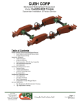
1
CUSH CORP
Suspensions & Product Service
Company Name: ______________________________
Catalog Date: _________________________________
Cush Corp
1001 Falconcrest Ct.
Nixa, Mo 65714
Phone: (417) 724-1239
Fax: (417) 724-0126
www.cushcorp.com
Giving the World a Better Ride!
Page: 1
Pub: P1203-01 Rev: 6
October 10, 2007
CUSH SUPENSIONS SYSTEMS
SERVICE MANUAL
CUSH Suspension Systems
Service Manual
Table of Contents
Inspection Schedule
Original Inspection
Daily Inspection
30-day Inspection
90-day Inspection
Axle Alignment Inspection
Axle Inspection
Post Inspection Notes
Suspension Maintenance Items
Caution Notes
Trailer Lean or Dog Tracking
Torque Specifications
Customer Welding Notes
Warranty Note
Suspension Service Items-Warranty Labor Allowances
Axle Alignment Styles
Shock Absorber
Air Spring
Chain Restraint
Axle Attaching U-Bolts
Shear-type Pivot Bolt
Pivot Components
Suspension Frame Hanger (Welded type)
Suspension Frame Hanger (Bolt-on type)
Suspension Trailing Arms & Axle (H-Beam)
OEM Reference WLA
Height Control Valve
Service Appendixes
A-Troubleshooting Guide
B-Service Parts Cross-reference
C-Specific Service Bulletin Literature
D- Cush Trailer Suspension Parts Explosion Drawings
Installation Procedures Appendixes
I1-Suspension to Axle Weld Procedures
I2-Recommended Frame Welding Ref Drawing
Giving the World a Better Ride!
Page: 2
Pub: P1203-01 Rev: 6
October 10, 2007
CUSH SUPENSIONS SYSTEMS
SERVICE MANUAL
Inspection Schedule
The following inspection schedule is a guide to help with the preventative maintenance
of your suspension system. Your air suspension will provide many trouble free miles of
service by using the information in this publication.
Original Inspection
When reviewing the suspensions on your trailer for the first time, check the following:
The axles have been aligned properly.
The suspension frame bracketry and air spring plate mountings have been
properly supported.
The suspension ride height is set properly.
Trailer is level
All welds are of good and acceptable quality
All fasteners are in place and securely torqued
No component interferences are visible
No air spring, air-lines, or shock absorber leaks are visible
There should be 0.75" minimum clearance must be maintained around air spring
when it is at maximum diameter.
There should be 1" minimum clearance between top of tire and bottom of trailer
structure when axle is at full jounce.
There should be 2" minimum clearance between inside of tire and trailer frame
structure for lateral movement.
There should be ample fore and aft clearances.
Daily Inspection
A quick visual inspection before operating the trailer will often detect obvious problems
such as broken or loose parts.
30-day Inspection
Check clearances around all moving suspension parts such as air springs, tires, and
shock absorbers for any signs of wear or component interferences.
Check each of the following:
Fasteners Not loose, broken or missing
Pivot Bushing Not protruding, off-center, torn or worn
Pivot Washer Not worn through or torn
Chain Restraint Not elongated or broke
Shock Absorber - Not leaking or damaged
Air Spring - Not leaking, worn, or damaged
Air Control Trailer maintains ride height; no leaking or damaged valves, fittings,
or piping
Frame Hanger Not worn, cracked, bent, or damaged
Suspension Beam Not worn, cracked, bent, or broken
Beam/Axle Not cracked, bent, or broken
Tires No tire wear that might indicate an alignment problem.
Axle Alignment No pivot gear movement or inappropriate wear, axles tracking
properly
Giving the World a Better Ride!
Page: 3
Pub: P1203-01 Rev: 6
October 10, 2007
CUSH SUPENSIONS SYSTEMS
SERVICE MANUAL
Trailer Trailer not leaning, trailer frame suspension attachment structurally
sound, no cracked or missing welds at suspension frame attachment.
90-day Inspection and at every brake lining change
Thoroughly check all items checked at the 30-day inspection. Also check:
All welded connections for signs of deterioration
All frame attachment joints and pivoting or clamping joints for problems
Axle Alignment Inspection
Check the Cush-Align connection for change of position at 30-day, 90-day, and every
brake lining change. Re-align if necessary.
Axle Inspection (general notes, see axle manufacture s service manual for
details)
Visually inspect the seal and hub cap for leaks and oil level every 7,500 miles (if oil bath
type). Repair if necessary.
At 100,000 miles or 12 months, visually inspect seal and hub cap for contaminants, oil
level, or leaks. Check the wheel bearing adjustment. Repair if necessary.
Post Inspection Notes
If issues arise from any inspection, review troubleshooting guide (Appendix A of this
service manual). If the issue can t be resolved from the troubleshooting guide or for
warranty information, contact your trailer manufacture. If the problem is not related to
installation, the trailer manufacturer or suspension installer should contact Cush to
resolve the issue or file the warranty claim.
Suspension Maintenance Items
The Cush trailer air suspension system is designed to minimize service issues. With
proper maintenance the life of your suspension system can be extended.
Caution Notes
Trailer walk can occur due to loading, unloading, or loss of air spring pressure.
For safe loading and unloading, dump air spring pressure to lower vehicle.
Do not tow or pull on vehicle by suspension components.
Fasteners should never be reused, over-torqued, or lubricated.
Do not operate vehicle suspension with:
Broken welds or metal parts
Loose, broken, or missing fasteners or suspension components
Loss of air pressure in air springs or brake system
Trailer Lean or Dog Tracking
If your trailer is having problems with Lean or Dog Tracking please refer to the
Troubleshooting guide in Appendix A of this manual.
Giving the World a Better Ride!
Page: 4
Pub: P1203-01 Rev: 6
October 10, 2007
CUSH SUPENSIONS SYSTEMS
SERVICE MANUAL
Torque Specifications
It is the customer's responsibility to check and tighten fasteners to specified torque at
installation, after the suspension has been in operation for 3000 miles, and at
suspension inspection cycles. Failure to do so can result in loss of warranty.
Torque values given are specified for the fasteners in the condition supplied by
Cush Corporation.
DO NOT APPLY ANY ADDITIONAL LUBRICANTS.
!CAUTION: Fasteners should never be reused if removed or loss of clamp load
occurs. For proper joint clamping contact Cush for replacement fasteners or use
fasteners of equal strength.
!CAUTION: Over-torquing fasteners could result in material failure.
Common Torque Specifications (See Cush Safety and Inspection Sticker on your trailer)
AIR SPRING PROVIDED MOUNTINGS
SIZE Threaded Studs
3/8" 24-UNF STUD
3/8" 16-UNC BLIND NUT
1/2" 13-UNC STUD
1/2" 13-UNC BLIND NUT
3/4" 16-UNF COMBO STUD
Air Ports
1/4" 18-NPTF AIR FITTING
1/2" 14-NPTF AIR FITTING
MAX.
(ft*lbs.)
20
25
25
50
50
11
23
(Ft*Lbs)
(Nm)
General Fastener Torque Specs
Size
Thread
Grade
Min.
Max.
Min
Max.
Spring Keeper Bolt & Nut
1/2
13-UNC
5/B
65
75
88
102
TRAC-ALIGN Rack Lock Bolt
1/2
13-UNC
5/B
25
35
34
47
(10K) U-Bolt Nut
5/8
11-UNC
8/C
180
210
244
285
Brake Chamber Mounting Nut
5/8
11-UNC
5/B
100
110
136
149
Nyloc Jam Nut
3/4
10-UNC
A/B
80
100
108
136
Shock Mount Nut/Bolt
3/4
10-UNC
5/B
210
235
285
319
CAP Spring Pivot Bolt & Nut
3/4
10-UNC
8/C
330
380
447
515
(15K) U-Bolt Nut
3/4
10-UNC
8/C
330
380
447
515
(25K) U-Bolt Nut
7/8
14-UNF
8/C
475
525
644
712
Pivot Nut (SecureLok/Securex)
7/8
14-UNF
8/C
550
600
746
813
Giving the World a Better Ride!
Page: 5
Pub: P1203-01 Rev: 6
October 10, 2007
CUSH SUPENSIONS SYSTEMS
SERVICE MANUAL
Customer Welding Notes:
It is the responsibility of the suspension installer and vehicle designer to provide
adequate vehicle frame design, gusset support in the area of suspension
attachment, and proper securing method for the suspension system. The
suspension installer has the responsibility to determine the proper welding
parameters for the materials being used. For specifications of suspension
component materials, contact Cush.
Required cross member locations are shown. Actual size and shape may vary
per trailer design. It is the responsibility of the suspension installer to ensure
structural adequacy of the trailer frame and related cross members.
No welding of any of the suspension components is permitted, except where
specified by Cush.
Any alteration of the suspension components or installation deviations must be
approved, in writing, by Cush Corporation.
Recommended Steel Welding Procedures, If Required:
WARNING: If these procedures and specifications are not followed, damage to
the axle or suspension could result. The resulting axle or suspension damage
could cause an accident, property damage, and/or serious injury.
A welder qualified in 2G positions per ANSI/AWS D1.1-94 Section 5 Part C
"Welder Qualification" must perform the welding.
The specification shown below is for horizontal (2F) positioning.
Suspension components and their mating parts must be at a minimum
temperature of 60°F(15.5°C) and free from moisture, dirt, scale, paint, grease,
and other contaminates.
All welds must be performed in a flat, or horizontal, position.
Achieve spray arc transfer with the following welding parameters:
Standard Electrode: AWS E-7018(Oven Dried), 0.125"DIA., 120-140 AMPS D.C.,
Electrode positive.
Standard Wire: AWS ER-70S-6 or AWS ER-70S-3, 0.045"DIA
Volts: 26-30 DCRP
Current: 275-325 AMPS
Wire Feed Speed: 380-420 Inches per Minute
Electrode Extension: 0.75" to 1"
Gas: 86%AR 14%CO2 at 30 to 35 CFH
Any deviation from these welding parameters must be of equal strength or approved by
Cush Corporation in writing.
Warranty Note
If after review of the Cush Corp Warranty it is determined that there is a warranty issue
and Cush Corp has been notified, then a Warranty Labor Allowance may be needed.
The WLA for the following service items are shown with each itemized description. The
service item descriptions include the obvious parts involved, other parts may be involved
to complete the warranty repair. Shop per-hour labor rate allowances will not exceed
standard industry averages for the work done. Warranty claims should be filed per the
Cush Corp Warranty (publication P0202-01) with an itemized list of charges and copies
of all available receipts.
Giving the World a Better Ride!
Page: 6
Pub: P1203-01 Rev: 6
October 10, 2007
CUSH SUPENSIONS SYSTEMS
SERVICE MANUAL
Suspension Service Items
Axle Alignment
Cush has several different alignment means available for different applications. Listed
here are some general alignment guidelines and alignment procedures for the styles of
Cush Alignment.
CAUTION: DO NOT APPLY undercoating to the "Cush-Align" area until after alignment
and torque of the suspension pivot bolts.
Check that the tire inflation pressure is correct on all tires.
Alignment should be performed with the vehicle empty and the brakes released.
On a level floor move the vehicle forward and back to straighten, make sure last
movement is forward.
Remove the outer tires and any other parts from under the chassis that obstruct
the measuring distances between the kingpin and the axle ends. If you use a
commercially available kingpin and axle spindle extenders or the edge of the
wheel rim, you will not need to remove this equipment.
Measuring from the trailer's kingpin, determine the alignment of the forward axle.
After achieving proper alignment of the forward axle, torque the Cush Pivot
fasteners per Cush torque specifications on the Cush installation drawing.
Align, to within 0.063" tolerance, any additional axles to the forward axle per the
"Cush-Align" method. Use a commercially available alignment gauge or trammel
bar if available (see Figure 2).
(Figure 2)
Std Warranty Labor Allowance__0.5 (hours/axle)
NOTE: Failure to follow the procedure for your axle alignment application and/or properly
torque the pivot fasteners can result in a failed pivot connection and a loss of warranty
coverage!
Giving the World a Better Ride!
Page: 7
Pub: P1203-01 Rev: 6
October 10, 2007
CUSH SUPENSIONS SYSTEMS
SERVICE MANUAL
Cush Alignment Style 1
Cush-Align Original (1 alignment / inner flanged collars / 1/4 thk gears)
The Cush-Align" pivot joint features outside gear tooth washers that cover the alignment
slot and mate with a grounded rack plate. At the inside of the hanger, collars guide the
bushing and cover the alignment slot.
If realigning, and the gear washer is welded to the side of the hanger, grind the
welds loose without gouging the side of the hanger. Remove the gear washers
and clean away weld material.
Snug the bolts of the "Cush-Align" to be tight enough to hold the joint together
but loose enough to permit use of the alignment gear.
Set the alignment gear indicator tab at 6 o'clock, the neutral position. This gives
you pivot movement fore and aft. Be sure that there is one tooth of the gear
washer outside of the hanger rack, both sides, to be at the middle of the hanger
slot (see Figure 1).
(Figure 1)
To align the axle, rotate the alignment gear of one side of the suspension to get
the axle aligned. If needed, go to the other side of the suspension and rotate the
alignment gear in the opposite direction to fully align the axle. As standard, there
are two alignment gears per hanger. Use the gear on the outside of the hanger to
set the alignment and the inside gear for fine-tuning of the alignment.
NOTE: Before tightening the pivot connection fasteners, be sure that the spacer collars
are against the bushing inner metal and hanger side. Failure to follow these procedures
and/or properly torque the pivot fasteners at this time can result in a failed pivot
connection and a loss of warranty coverage!
WARNING: After alignment, clamp the joint per Cush bolt/nut torque specifications. After
alignment, the suspension installer can weld the gear washer to the hanger side with
1/2" welds both sides of washer to prevent tampering & for off-road applications, we
recommend for abusive applications.
Giving the World a Better Ride!
Page: 8
Pub: P1203-01 Rev: 6
October 10, 2007
CUSH SUPENSIONS SYSTEMS
SERVICE MANUAL
Cush Alignment Style 2
Cush-Align II Econo (3/4 alignment / 1/2 thk gears)
The Cush-Align II" pivot joint features outside gear tooth washers that cover the
alignment slot and mate with a grounded rack plate. After alignment, clamp the joint per
Cush torque specifications. After alignment, the suspension installer can weld the gear
washer to the hanger side with 1/2" welds both sides of washer to prevent tampering &
for off-road applications.
If realigning, the gear washer may be welded to the side of the hanger, grind the
welds loose without gouging the side of the hanger. Remove the gear washers
and clean away weld material.
Snug the bolts of the "Cush-Align" to be tight enough to hold the joint together
but loose enough to permit use of the alignment gear.
Set the alignment gear indicator tab at 6 o'clock, the neutral position. This gives
you pivot movement fore and aft. Be sure that there is one tooth of the gear
washer outside of the hanger rack, both sides, to be at the middle of the hanger
slot.
To align the axle, rotate the alignment gear of one side of the suspension to get
the axle aligned. If needed, go to the other side of the suspension and rotate the
alignment gear in the opposite direction to fully align the axle. As standard, there
are two alignment gears per hanger. Use the gear on the outside of the hanger to
set the alignment and the inside gear for fine-tuning of the alignment.
WARNING: After alignment, clamp the joint per Cush bolt/nut torque specifications. After
alignment, the suspension installer can weld the gear washer to the hanger side with
1/2" welds both sides of washer to prevent tampering & for off-road applications, we
recommend for abusive applications.
Giving the World a Better Ride!
Page: 9
Pub: P1203-01 Rev: 6
October 10, 2007
CUSH SUPENSIONS SYSTEMS
SERVICE MANUAL
Cush Alignment Style 3
Trac-Align (3/4 alignment / 1/2 thk eccentric / optional locking rack)
The Trac-Align" was designed to give our customers extra pivot integrity with the
addition of the optional locking rack and a more familiar alignment means with the use
of an eccentric cam adjustment. The Trac-Align" also has bearing washer with tabs for
use with a Cush axle-welding stand to have a more precise fixturing of the suspension
and axle at factory or customer integration.
*Please note that the tabs on the inner bearing washer can be in any position
after installation, as they do not indicate pivot alignment.
After alignment, clamp the joint per Cush torque specifications. After alignment, the
suspension installer can weld the outside washer to the hanger side with 1/2" welds to
prevent tampering & for off-road applications.
If realigning, loosen the rack lock bolts to allow eccentric cam
movement.
The eccentric cam gear should always have the ½ square hole
to the top.
Set the alignment gear indicator tab at 6 o'clock, the neutral
position. Snug the rack lock bolts and pivot bolts of the "TracAlign" to be tight enough to hold the joint together but loose
enough to permit use of the eccentric cam adjustment. Be sure
that the eccentric cam plate is clamped down flush against the
hanger side and is not riding up the grounding nuts/bars.
For adjustment use a breaker bar in the ½ square hole or use a
box wrench on the lower eccentric cam gear nut.
The Trac-Align gives you 3/8 pivot movement fore and aft per
hanger side. (see Figure 1)
To align the axle, rotate the alignment gear of one side of the
suspension to get the axle aligned. If needed, go to the other
side of the suspension and rotate the alignment gear in the
opposite direction to fully align the axle.
WARNING: After alignment, clamp the pivot bolt per Cush torque specifications. Torque
the ½ rack lock bolts to 25 ft*lbs, loosen the rack lock bolts to realign pivot.
Giving the World a Better Ride!
Page: 10
Pub: P1203-01 Rev: 6
October 10, 2007
CUSH SUPENSIONS SYSTEMS
SERVICE MANUAL
Cush Alignment Style 4
T-Align (3/8 alignment on street side / for Spring Suspensions)
The T-Align" was designed to give our customers that use a leaf spring suspension axle
adjustability at the frame hanger rather than having to loosen u-bolts and adjust at the
axle seat. The T-Align" is a positive adjustment that works with springs to eliminate
springs affecting the alignment process.
Overview; The "T-Align" pivot joint features a yoke assembly that covers the alignment
slot. After alignment, clamp the joint per Cush torque specifications. No weld is required
to secure the slip joint after proper tightening.
Remove load from trailer (empty). Jack the trailer up on a level surface and place
appropriate jack stands of sufficient strength/capacity to support the load under
the axle near the spring seat areas.
Tighten all fasteners on the R.H. Curb Side of trailer suspension.
Check that the keeper bolts are not clamping the sides of the springs causing
them to be locked by the rear hangers or equalizer.
With ratchet, turn the alignment bolt on the yoke assembly (L.H. ROAD SIDE) so
that the pivot bolt is at the "CENTER OF THE SLOT" on the front hanger &
equalizer. DO NOT USE AN IMPACT GUN. (Fig 1)
Hand tighten (snug) the pivot nuts of the "T-Align" to be tight enough to hold the
joint together but loose enough to permit forward movement of the alignment
yoke (able to loosen by hand).
Block the top side of each equalizer between the frame with 2 blocks (3-1/8" tall)
per side, to keep level. (Fig 2)
Measure from the trailer's kingpin to determine the alignment required on the
front axle (L.H. ROAD SIDE) to within 1/16".
After achieving proper alignment of the forward axle, torque pivot fasteners per
Cush installation drawing
Align additional rearward axles to within 1/16" tolerance of the forward axle per
the "T-Align" method.
Giving the World a Better Ride!
Page: 11
Pub: P1203-01 Rev: 6
October 10, 2007
CUSH SUPENSIONS SYSTEMS
SERVICE MANUAL
Shock Absorber
The shock absorber is used to dampen the bouncing of an air spring suspension.
Without shocks in place damage can occur to the suspension or trailer. Shocks are a
replaceable item of an air suspension and when maintained can extend the life of your
air suspension and trailer. Some things can indicate it is time to replace shocks: Uneven
tire wear, poor ride characteristics, broken or torn air springs.
Inspection:
o Broken upper or lower shock eye mounting at the welds
o Worn out upper or lower shock eye bushings
o Broken dust tube cover
o Bent or dented lower shock body tube
o Bent shock rod
o Shock leaking streams of oil
To replace a shock absorber:
Contact your trailer manufacture or Cush Corp for replacement parts or cross-reference
Remove the shock end mounting hardware
Check the mounting surface for wear problems
Insert the new shock absorber and appropriate mounting hardware
Torque the fasteners to specification
Warranty Labor Allowance__0.3 (hours each)
(See the troubleshooting guide for more information on shock absorber issues)
Air Spring
The air spring is used to carry and cushion the load of an air spring suspension. Without
an air spring in place damage can occur to the suspension or trailer. If damaged, air
springs are a replaceable item and when maintained can extend the life of your air
suspension and trailer. Air Springs can also be used to lift the suspension, observe the
same safety precautions below when changing lift springs.
To replace an air spring:
Contact your trailer manufacturer or Cush Corp for replacement parts or cross-reference
Support the trailer in a safe manner at a working height prior to exhausting the air
Exhaust all air from the air suspension system
Disconnect the air fittings from the air spring
Remove the mounting hardware from the air spring and remove the air spring
Check the mounting surface for wear problems
Insert the new air spring and appropriate mounting hardware
Torque the fasteners to specification
Reconnect the air fittings and air lines to the air spring
Lower the trailer
Supply air to the suspension system
Check for air leaks
Warranty Labor Allowance__0.3 (hours each)
(See the troubleshooting guide for more information on air spring issues)
Giving the World a Better Ride!
Page: 12
Pub: P1203-01 Rev: 6
October 10, 2007
CUSH SUPENSIONS SYSTEMS
SERVICE MANUAL
Chain Restraint
The chain restraint is a feature used to protect the shock absorber and air spring of your
trailer suspension from overextension. Without the chain restraint in place the
suspension will function but damage can occur to the shock absorber. Chain restraints
are a replaceable item of an air suspension and can extend the life of your shock
absorbers and air springs.
To replace a chain restraint:
Contact your trailer manufacturer or Cush Corp for replacement parts or cross-reference
Support the trailer in a safe manner prior to exhausting the air
Exhaust all air from the air suspension system
Remove the old chain restraint and attachment link
Check the mounting surfaces for wear problems
Check that the new chain restraint is the proper size and length to your old restraint
Insert the new chain restraint
Reconnect the attachment link, checking that the chain is not bound up
Supply air to the suspension system
Visibly check for any clearance issues with your new chain restraint
Warranty Labor Allowance__0.1 (hours each)
(See the troubleshooting guide for more information on chain restraint issues)
U-BOLT INSPECTION & INSTALLATION NOTES
CAUTION! Do not apply any lubricants to the u-bolts, improper clamp loading can occur causing
failure
Inspection
o
o
Check each U-bolt threaded area for damage or burrs.
After installation, an equal amount of thread should be visible beyond the head of the nut
on each side of the U-bolt.
Installation
o
U-Bolts should only be installed and torqued after completion of any axle welding. Allow
sufficient axle cooling time before applying torque to u-bolts.
o
Check that U-bolts fit properly in area, if U-bolt is to tight tap on top of U-bolt to hard
surface to open up. Be careful that U-bolt installation does not damage threads.
o
Snug all U-bolts evenly before applying clamping torque with hand wrench. Check that ubolts are parallel and square to axle.
o
Torque U-bolts in a three-step process to avoid an improperly clamped axle and
resulting damage. Torque the u-bolts in an "X" pattern with each torque step (12-3-4). This allows the U-bolt to stretch and relax for the clamp to hold torque.
Proper tightening will allow equal amount of tread above each nut.
o
Use a calibrated torque wrench to get the proper setting for the size of U-bolt you
are using:
o First Step-1/3 of Final torque
o Second Step-2/3 of Final torque
o Third Step-Final torque
Giving the World a Better Ride!
Page: 13
Pub: P1203-01 Rev: 6
October 10, 2007
CUSH SUPENSIONS SYSTEMS
SERVICE MANUAL
Shear-type Pivot Fastener
Some Cush suspension models may offer a Shear-type pivot fastener. This Shear-type bolt is
well known in the heavy-duty suspension market as being a fast and convenient way to apply the
proper torque. The same installation tooling can be used with the Cush units (Torx E-20) as
provided by: Hendrickson, Camcar, Strong Tools, & Apex. If a Torx E-20 socket is not available,
torque bolt nut per 7/8 Grade 8 spec (550-600ft*lbs).
The AudiTorx Shear-type bolt gives automatic torque clamping and consistent repeatability
because the Shear-type Torx E-20 drive head is designed with a cut groove to shear off at a predetermined torque level when applied with an air impact. After shearing off the Torx drive head a
36mm hex head is left for later service with a socket or wrench.
*AudiTorx Installation & Inspection Notes:
o Required Materials: E-20 Torx socket, 1-5/16 nut wrench, Air Impact wrench capable of
600 ft*lbs (813 N*m) Minimum, alignment tools.
o If a Torx E-20 socket is not available, torque bolt nut per 7/8 Grade 8 spec (550-600ft*lbs)
o DO NOT APPLY undercoating to the suspension hanger area until after axle alignment and
pivot bolt torque has been applied.
o Cush does not recommend reuse of pivot fastener hardware once the pivot connection is
disassembled, use a new bolt and nut.
o Check for proper tire clearance with fastener hardware. The AudiTorx bolt should be
installed from the inboard side of the frame hanger to allow access with an air impact when
tires are on, if tire clearance is an issue with fastener hardware, then the shear-type bolt
head should be installed from the outboard side.
o NOTE: Check for any flashing or obstructions to cause the bearing washers to be raised
and not allow flush mounting against the hanger sides (gear or eccentric type).
o Check proper axle alignment, see installation manual for instructions on alignment.
o Snug the pivot fasteners so that the alignment washers do not move while applying initial
torque, recheck alignment.
o Torque the shear-type pivot bolt with the E-20 Torx drive socket tool until the bolt s Torx
head shears off.
o The E-20 Torx drive socket should fully engage the Torx shear head before and while
applying torque.
o Apply paint to the sheared away Torx area as a rust preventative.
Warning!
It is the responsibility of the assembler (OEM, Dealer, Repair Facility, etc.) to inspect and insure
proper installation of the Shear-type bolt. If improperly torqued, the pivot clamp force can fail
resulting in unreliable axle alignment, vehicle instability, personal injury, and/or property damage.
Socket Description
E-20 Torx Socket
E-20 Torx Socket Heavy Duty
E-20 Torx Socket Heavy Duty w/Sleeve
Drive Size
3/4" Square
1" Square
1" Square
Cush Hendrickson Camcar Apex
V-24303
A-24303
TX-7120
V-24536
A-24536
TX-8120 E-20
V-25119
A-25119
Page: 14
Giving the World a Better Ride!
Pub: P1203-01 Rev: 6
October 10, 2007
CUSH SUPENSIONS SYSTEMS
SERVICE MANUAL
Pivot Components
The pivot of a trailing arm air ride suspension is the main link to connect the suspension
to your trailer. This link provides a resilient connection that allows an axle to walk without
excessive flexing. Re-bushing of a suspension requires the use of a bushing
removal/installation tool and bushing kit, containing the required components for rebushing. Contact Cush for information regarding the tool and the proper kit for your
suspension and review any instructions on your suspension drawing.
Disassembling Pivot Connection:
On level ground, securely chock the tires and apply trailer parking brakes
Support the trailer in a safe manner at a working height prior to exhausting the air
Exhaust all air from the air suspension system
Loosen and remove shock connection and chain restraint
Loosen and remove any jam nut
Loosen and remove pivot nut
Remove Pivot bolt and alignment gears
Disassemble any other parts that interfere with lowering the trailing arm/axle
assembly out of the suspension hangers
Using a hydraulic jack or other lifting device, lower pivot end of trailing arm/axle
from inside hanger. (Yoke suspensions will need to be pulled out from trailer
frame)
Bushing Replacement (Frame Hanger style):
Use Cush bushing replacement kit shown on parts explosion for your
suspension, or contact Cush Corp for cross-reference.
Some models, remove the flanged inserts from the inner diameter of the bushing
tube
Remove old bushing using bushing tool
Clean inside surface of trailing arm bushing sleeve
Lubricate outside of new Cush Dual-Rate bushing and inside of trailing arm
bushing sleeve with proper rubber lubricant (P-80 or Ru-glyde)
Orient voids in bushing within 5 degrees, (plus or minus) of vertical position
when suspension is in operation.
Center inner metal bushing in sleeve with the outer metal bushing housing with
tool, it may be necessary to push bushing thru a little and pull back to center
rubber and inner metal sleeve.
Reassembling pivot connection (Frame Hanger style):
Position wear washers over the outside diameter of the bushing tube
Some models, Install the flanged inserts in the inner diameter of the bushing tube
Place the pivot bolt through the partial assembly
Hand tighten a non-locking nut to hold the position of all loose items
Using a hydraulic jack or other lifting device, raise pivot end of trailing arm until
flanges of flanged inserts enter the inside of the hanger
Holding this raised position, remove pivot bolt and standard hex nut continue to
raise pivot end of trailing arm until hole in bushing lines up with slots in hanger
Place adjustment gear on pivot bolt per suspension drawing (Always use new
fastener hardware)
Giving the World a Better Ride!
Page: 15
Pub: P1203-01 Rev: 6
October 10, 2007
CUSH SUPENSIONS SYSTEMS
SERVICE MANUAL
Re-insert pivot bolt through side of hanger or yoke beam engaging all teeth of the
alignment gear as shown in Figure 1 (Note: one gear tooth outside of alignment
rack, both sides for neutral position).
Place adjustment gear on end of pivot bolt against inner face of hanger,
engaging all teeth of the alignment gear as shown in Figure 1 (Note: one gear
tooth outside of hanger rack, both sides for neutral position).
Place pivot nut on end of pivot bolt and tighten until snug to hold tooth
engagement of alignment gears
Using a wrench, move alignment gear pointers to nominal position
Align axle with relation to the kingpin as shown in Figure 2 (see Axle Alignment)
Reinstall shock absorbers and chain restraints
Torque all the fasteners to specification
Warranty Labor Allowance__5.0 (hours/axle)
(See the troubleshooting guide for more information on pivot connection issues)
Bushing Replacement (Frame Yoke style):
After removing the yoke style trailing arm/axle from the bushing frame area,
record how much offset each bushing side is to the trailer frame outer bushing
metal sleeve
The Yoke style bushing can be replaced with the bushing tool but it is usually
easier to replace the inner bushing and metal sleeve housing by removing the
small welds that connect the inner bushing housing to the frame sleeve housing,
suspension drawing.
Grind or torch the welds of the inner to outer housing without damaging the outer
frame housing tube. Remove old bushing and metal housing from trailer frame
and clean the outer frame housing tube for reuse.
Inspect trailer frame flange for damage.
Use Cush bushing replacement kit shown on parts explosion for your
suspension, or contact Cush Corp for cross-reference.
Reassembling pivot connection (Frame Yoke style):
Insert new bushing with metal sleeve and orient voids in bushing within 5
degrees, (plus or minus) of vertical position compared to the trailer frame.
See and mark bushing housing for vertical inspection, once washers cover voids
orientation can not be seen. (Cush marks bushing front with notch)
Position wear washers over the outside diameter of the bushing inner tube
Install the flanged insert spacers in the inner diameter of the bushing inner tube,
both sides
Place a pivot bolt through the partial assembly
Hand tighten a non-locking nut to hold the position of all loose items
Adjust the new bushing with sleeve in trailer frame sleeve per recorded
information so you can get the yoke beams and axle assembly started onto the
bushings flanged spacers. (Do not weld until after axle assembly is centered)
Using a hydraulic jack or other lifting device, raise pivot end of yoke trailing arm
until flanges of flanged inserts enter the inside of the yoke suspension beam
Holding this raised position, remove pivot bolt and standard hex nut continue to
raise pivot end of trailing arm until hole in bushing lines up with slots in yoke
beam
Giving the World a Better Ride!
Page: 16
Pub: P1203-01 Rev: 6
October 10, 2007
CUSH SUPENSIONS SYSTEMS
SERVICE MANUAL
Place adjustment gear on pivot bolt per suspension drawing (Always use new
fastener hardware)
Re-insert pivot bolt through side of yoke beam engaging all teeth of the alignment
gear as shown in Figure 1 (Note: one gear tooth outside of alignment rack, both
sides for neutral position).
Place adjustment gear on end of pivot bolt against inner face of yoke beam,
engaging all teeth of the alignment gear as shown in Figure 1 (Note: one gear
tooth outside of rack, both sides for neutral position).
Place pivot nut on end of pivot bolt and tighten until snug to hold tooth
engagement of alignment gears
Using a wrench, move alignment gear pointers to nominal position and snug
nut/bolt assembly.
Axle assembly with yoke beams need to be centered on trailer frame and aligned
with other trailer tires outside position.
Once axle has been positioned side to side on trailer frame, recheck that bushing
voids are in vertical position and weld bushing inner metal sleeve to trailer frame
bushing housing sleeve with ½ min welds 4 places around both sides of sleeve
each.
Do not worry about minor melting of plastic wear washer, do not catch washer or
bushing on fire.
Stagger the sequence of welding as to allow adequate cooling between welds to
prevent excessive heating of the bushing.
Align axle with relation to the kingpin as shown in Figure 2 (see Axle Alignment)
Reinstall any shock absorbers and chain restraints
Torque all the fasteners to Cush specification
Warranty Labor Allowance__5.0 (hours/axle)
(See the troubleshooting guide for more information on pivot connection issues)
Pivot Wear Washer
The pivot wear washer is used to prevent metal-to-metal contact of the suspension
beam and the inside of the hanger. These wear washers can cup and misshape and still
function. At the point the wear washer is worn thru, they should be replaced to prolong
the life of the suspension.
To replace wear washers:
Contact your trailer manufacturer or Cush Corp for replacement parts or crossreference
On level ground, securely chock the tires and apply trailer parking brakes
Support the trailer in a safe manner at a working height prior to exhausting the air
Exhaust all air from the air suspension system
Disassemble the pivot connection and any other parts that interfere with lowering
the axle/beam assembly out of the suspension hangers
Lower the axle beam assembly, check for any damaging hanger wear
Remove the flanged inserts from the inner diameter of the bushing tube
Remove the old wear washers
Check for any damaging beam, hanger, or insert wear
Insert the new wear washers and appropriate flanged inserts
Place a pivot bolt through the partial assembly
Giving the World a Better Ride!
Page: 17
Pub: P1203-01 Rev: 6
October 10, 2007
CUSH SUPENSIONS SYSTEMS
SERVICE MANUAL
Hand tighten a standard hex nut to hold the position of all loose items
Raise the axle/beam assembly and reassemble the pivot connection, use new
pivot bolts & nuts
Reassemble any other parts that were disassembled to lower axle/beam
assembly
Align axle with relation to the kingpin as shown in Figure 2 (see Axle Alignment)
Torque all the fasteners to specification
Warranty Labor Allowance__2.0 (hours/axle)
(See the troubleshooting guide for more information on wear washer issues)
Cush Corp Suspension Fabricated Components
Some issues are discussed here but if other deficiencies occur contact your trailer
manufacturer or Cush Corp for information.
Suspension Frame Hanger (Welded type)
Cush manufactures various hangers for different applications; because of this it would
be best for you to contact Cush for an installation drawing per your application. On these
drawings we show recommended cross-member and support locations. Failure to have
the proper support in place can cause a reoccurring failure mode. If for some reason it is
required to replace a frame hanger, please follow the guidelines below as a minimum
safety procedure when repairing these items.
To replace welded frame hanger:
Contact your trailer manufacturer or Cush Corp for replacement parts
On level ground, securely chock the tires and apply trailer parking brakes
Support the trailer in a safe manner at a working height prior to exhausting the air
Exhaust all air from the air suspension system
Disassemble the pivot connection and any other parts that interfere with lowering
the axle/beam assembly out of the suspension hangers
Lower the axle beam assembly, check for any damaged beam wear
Check that the wear washers are in usable condition
Check that the bushing inserts are in usable condition
Mark the hanger position on the frame side for reference
Cut away the frame hanger and clean up the frame with grinder, do not gouge
frame
Put new hanger component on beam/bushing and reassemble the pivot
connection, use new pivot bolts & nuts
Move the alignment gears to the nominal notch position and snug up hanger bolt
Raise the axle/beam/hanger assembly to the frame and clamp hanger to frame
squarely
Weld hanger to frame per Cush Corp installation drawing
Reassemble any other parts that were disassembled to lower axle/beam
assembly
Align axle with relation to the kingpin as shown in Figure 2 (see Axle Alignment)
Torque all the fasteners to specification
Warranty Labor Allowance__4.0 (hours each or 6.0 hours/axle)
(See the troubleshooting guide for more information on frame hanger issues)
Giving the World a Better Ride!
Page: 18
Pub: P1203-01 Rev: 6
October 10, 2007
CUSH SUPENSIONS SYSTEMS
SERVICE MANUAL
Suspension Frame Hanger (Bolt-on type)
To replace a bolted frame hanger:
Contact your trailer manufacturer or Cush Corp for replacement parts
On level ground, securely chock the tires and apply trailer parking brakes
Support the trailer in a safe manner at a working height prior to exhausting the air
Exhaust all air from the air suspension system
Disassemble the pivot connection and any other parts that interfere with lowering
the axle/beam assembly out of the suspension hangers
Lower the axle beam assembly, check for any damaged beam wear
Check that the wear washers are in usable condition
Check that the bushing inserts are in usable condition
Unbolt the frame hanger and discard the used fasteners
Inspect trailer frame for damage
Use new mounting hardware, grade 8, and torque bolts to trailer mfg
specification
Mount new hanger component to trailer frame
Raise the axle/beam assembly to the hanger and reinstall beam
Bolt hanger to frame per Cush Corp installation drawing
Reassemble any other parts that were disassembled to lower axle/beam
assembly
Move the alignment gears to the nominal notch position and snug up hanger bolt
Align axle with relation to the kingpin as shown in Figure 2 (see Axle Alignment)
Torque all the fasteners to specification
Warranty Labor Allowance__3.0 (hours each or 5.0 hours/axle)
(See the troubleshooting guide for more information on frame hanger issues)
Suspension Trailing Arms & Axle (H-Beam)
Cush manufactures various trailing arms for different applications; because of this it
would be best for you to contact Cush for an installation drawing per your application. On
these drawings we show recommended cross-member and support locations. Failure to
have the proper support in place can cause a reoccurring failure mode. Contact Cush to
see if it is required to replace the trailing arm or the H-Beam of the suspension, please
follow the guidelines below as a minimum safety procedure when repairing these items.
Suspension H-Beam
To replace the suspension H-Beam (Beam-only axle replacement with a pair of
trailing arms):
Contact your trailer manufacture or Cush Corp for replacement parts and
installation drawings
On level ground, securely chock the tires and apply trailer parking brakes
Support the trailer in a safe manner at a working height prior to exhausting the air
Exhaust all air from the air suspension system
Remove the Brake chambers, leave the air lines attached
Remove the Slack adjusters and mounting hardware, shims and pins
Remove the ABS valves and sensor wiring from the H-Beam
Remove the air spring connections to the H-beam
Remove the shocks and mounting hardware from H-Beam
Remove the Height control valve connection to the H-Beam
Giving the World a Better Ride!
Page: 19
Pub: P1203-01 Rev: 6
October 10, 2007
CUSH SUPENSIONS SYSTEMS
SERVICE MANUAL
Disassemble the pivot connection and any other parts that interfere with
removing the H-Beam assembly from the suspension hangers and from the
trailer frame
Lower the axle beam assembly or lift the trailer to drop the H-Beam
Check for any damaged hanger wear
Remove the axle assembly from under the trailer
Remove the tires, wheels and proceed to strip axle
Remove the wheel nuts, drums, spindle nut, and hubs from the axle
Remove bearings and seals from the axle
Remove the brake lining shoes and springs from the axle
Remove the bushing inserts and wear washers from bushing, reuse if necessary
Install the new H-Beam assembly from Cush Corp
Reinstall the axle components and then roll the axle assembly under the trailer
Raise the H-Beam, lower the trailer to working height, and reassemble the pivot
connection
Hook up all air lines and check for leaks
Reassemble any other parts that were disassembled to lower axle/beam
assembly
Move the alignment gears to the nominal notch position and snug up hanger bolt
Align axle with relation to the kingpin as shown in Figure 2 (see Axle Alignment)
Torque all the fasteners to specification
Package the damaged H-Beam assembly for shipment to Cush Corp, contact
Cush for pick up
Warranty Labor Allowance__8.0 (hours/H-Beam)
Giving the World a Better Ride!
Page: 20
Pub: P1203-01 Rev: 6
October 10, 2007
CUSH SUPENSIONS SYSTEMS
SERVICE MANUAL
Original Equipment Manufacturer s Warranty Reference WLA
Warranty for the following non-exclusive list of parts, (if supplied by Cush), will default to
the Manufacturer s Warranty, and no labor to repair or replace these parts unless
allowed. If damage to these parts is caused by a defect from a Cush Corp product then
use these WLA as a guide when filing an approved warranty claim.
Ride Height Control Valve
The ride height control valve (HCV) is used to carry and cushion the load of an air spring
suspension. Without an HCV in place damage can occur to the suspension or trailer. If
damaged, HCV are a replaceable item and when maintained can extend the life of your
air suspension and trailer. The HCV should maintain equal air spring heights for a set of
grouped suspensions that are the same to maintain equal load carrying. When the
suspension is lowered from loading the HCV lever arm moves up and adds air to the
suspension air springs. When the suspension is raised from unloading the HCV lever
arm moves down and removes air from the suspension air springs in order to bring the
arm back to neutral position. The HCV is covered under the original OEM of the valve
and this procedure is given as a guide only.
To replace a Height Control Valve:
Contact your trailer manufacturer or Cush Corp for replacement parts or crossreference
Support the trailer in a safe manner at a working height prior to exhausting the air
Exhaust all air from the air suspension system
Disconnect the air fittings from the HCV
Remove the mounting hardware from the HCV and remove the HCV
Insert the new HVC and appropriate mounting hardware
Torque the fasteners to specification
Reconnect the air fittings and air lines to the HCV
Supply air to the suspension system
Check for air leaks with soapy water
Set the trailer at ride height by adjusting the HCV to allow air in or out
Pin the HCV handle (horizontal arm) thru the hole to the HCV and adjust the
vertical linkage
Mount the vertical linkage bottom pin in place to the closest hole when using a
fixed vertical link
Mount the vertical linkage bottom pin in place and adjust the link in the pgrommet and clamp the grommet collar in place when set with the handle pinned
to the HCV center position
Caution Remove HCV centering pin otherwise damage to HCV could occur
Reference Warranty Labor Allowance__1.0 (hours each-Contact Original Manufacturer)
Giving the World a Better Ride!
Page: 21
Pub: P1203-01 Rev: 6
October 10, 2007
CUSH SUPENSIONS SYSTEMS
SERVICE MANUAL
(Barksdale Height Control Valve Installation)
Physical Description
The Barksdale Height Control Valve (HCV) is a three-mode valve used to control the
height of a vehicle by directing air to the air spring suspension. The main physical
features of the valve are the following; (2) delivery ports*, (1) Exhaust port, (1)
inlet/supply port, (1) Height Control Handle, and (2) ¼ Mounting Studs.
(* All ports are ¼ NPT, the (2) delivery ports are clearly marked, C1 and C2 on the
back of the valve.)
Modes of Operation
The three modes of operation of the HCV are as follows;
1. Fill Mode
2. Exhaust Mode
3. Dead Band Mode
When the vehicle suspension is at the factory set ride height, the valve will be in Dead
Band Mode. In Dead Band Mode, the Valve will not allow air to flow in or out of the air
bags. As the vehicle becomes laden, the suspension will settle, causing the handle of
the valve to rotate upwards. The valve will now enter Fill Mode, allowing air to enter the
air bags, causing the vehicle to rise. As the vehicle approaches factory set ride height,
the valve will once again enter Dead Band Mode. Similarly, if the bus is unloaded, the
suspension will rise causing the control handle of the valve to rotate downward. When
the handle rotates downward, the valve enters exhaust mode, thereby letting air out of
the air bags, causing the vehicle to lower until Dead Band Mode is reached again at the
factory set ride height.
Installation
Attach all fittings to valve before mounting to vehicle. Thread sealant must be
applied to all fittings, which are tightened by hand until firm, at which point a wrench
should be used to tighten additional 1- 1 ½ turns.
Recommended proper orientation for the valve handle for installation is when the
valve handle is in line with the C1 port.
Mount the Valve to a bracket using the ¼ studs. Do not fully tighten nuts at this
time, to allow fine-tune adjustment of ride height. Attach Air Supply line to the port at the
top of the valve. Attach the air bag air lines to the C1 and C2 ports.
Set-Up
1. Adjust approximate ride height by turning the valve handle up toward the air
supply line to add air to the bags to raise the vehicle above the ride height, down
to exhaust air from the air bags to adjust to approximate ride height. Then put
the handle in the horizontal position.
2. Install wood Centering Pin in hole provided in valve handle.
3. Connect linkage from suspension mount to valve handle and tighten linkage.
4. Adjust to final factory recommended ride height by rotating the valve assembly
on the bracket.
5. Tighten nuts to 45 Inch pounds torque.
6. Remove the centering pin.
Giving the World a Better Ride!
Page: 22
Pub: P1203-01 Rev: 6
October 10, 2007
CUSH SUPENSIONS SYSTEMS
SERVICE MANUAL
Warranty Labor Allowances (hours each)
Air reservoir__1.0
Brake chamber__0.8
Brake hose (relay valve to brake chamber)__0.5
Quick release valve__1.0
Height control valve__1.0
Includes:
Removal and installation of height control valve and the linkage
Ride height adjustment at linkage
Height control valve linkage__0.5
Solenoid valve__1.0
Air pilot valve__1.0
Brake protection valve__1.0
Flipper valve__1.0
Hand control valve__1.0
Manual exhaust valve__1.0
ABS wheel sensor (one)__1.0 *
Includes:
Removal and installation of:
- Tire and wheel assembly
- Brake drum
Adjust ABS wheel sensors (up to four)__0.5 *
ABS relay valve__1.0 *
ABS modulator valve__1.1 *
ABS electronic control unit (ECU)__1.1 *
Slack adjuster__0.7
Brake camshaft
(Does not require hub removal)__1.2
Includes:
Removal and installation of:
- Tire/wheel assembly
- Slack adjuster
Brake adjustment
Brake cam tube assembly
(Does not require wheel, drum, or hub removal)__1.0
Includes:
Removal and installation of:
- Cam tube weld/re-weld
- Slack adjuster
Brake adjustment
Giving the World a Better Ride!
Page: 23
Pub: P1203-01 Rev: 6
October 10, 2007
CUSH SUPENSIONS SYSTEMS
SERVICE MANUAL
Wheel end (tire and wheel removal and installation)
Inner wheel seal__1.0
Hub__1.4
Wheel studs (up to three)__1.7
Hub cap/gasket__0.5
* Includes troubleshooting
Troubleshooting Guide
P1203-01 Appendix A (Contact Cush): Use this guide to review possible suspension
maintenance and service issues, possible causes of issues, and possible solutions.
Contact Cush Corp before cutting or welding on any suspension components that could
void your warranty.
Service Parts Cross-reference Guide
P1203-01 Appendix B (Contact Cush): Use this guide to review possible Cush
suspension service parts cross-referenced to competitive part numbers that might be
more readily available to you.
Specific Service Bulletin Literature
P1203-01 Appendix C (Contact Cush): If deemed necessary by Cush Corp we will
publish a service bulletin specific to a certain suspension application issue. Contact
Cush Corp to see if there is a service bulletin that might help with your specific service
situation.
Cush Suspension Parts Explosion Drawings
Drawings may vary per your application (Contact Cush for drawings)
Giving the World a Better Ride!
Page: 24
Pub: P1203-01 Rev: 6
October 10, 2007
CUSH SUPENSIONS SYSTEMS
SERVICE MANUAL
P1203-01 Appendix I1
Cush Suspension to Axle Welding Procedures
RECOMMENDED STEEL WELDING PROCEDURES:
WARNING: If these procedures and specifications are not followed, damage to the axle or
suspension could result. The resulting axle or suspension damage could cause an accident,
property damage, and/or serious injury.
NOTE: A welder qualified in 2G position per ANSI/AWS D1.1-94 Section 5 Part C "Welder
Qualification" must perform the welding.
NOTE: The specification shown below is for horizontal (2F) positioning.
1) Suspension components and their mating parts must be at a minimum temperature of
60°F(15.5°C) and free from moisture, dirt, scale, paint, grease, and other contaminates. (Pre-heat
per axle manufacturer)
2) All welds must be performed in a flat, or horizontal, position. Clean welds between each pass.
Standard Wire: AWS ER-70S-6, 0.045"DIA
Volts: 26-30 DCRP
Current: 275-325 AMPS
Gas: 90%AR 10%CO2 at 30 to 35 CFH
If these procedures and specifications are not followed, damage to the axle or suspension could
result. The resulting axle or suspension damage could cause an accident, property damage,
and/or serious injury.
NOTE: A welder qualified in 2G position per ANSI/AWS D1.1-94 Section 5 Part C "Welder
Qualification" must perform the welding.
NOTE: The specification shown below is for horizontal (2F) positioning.
1) Suspension components and their mating parts must be at a minimum temperature of
60°F(15.5°C) and free from moisture, dirt, scale, paint, grease, and other contaminates. (Pre-heat
per axle manufacturer)
2) All welds must be performed in a flat, or horizontal, position. Clean welds between each pass.
Standard Wire: AWS ER-70S-6, 0.045"DIA
Volts: 26-30 DCRP
Current: 275-325 AMPS
Gas: 90%AR 10%CO2 at 30 to 35 CFH
Note: Brake camshaft to be located according to axle manufacturer specifications &
suspension/trailer model.
Use locating fixture or flat surface to space suspension beams and center axle. Check that
suspension beams are: parallel, square to axle, and perpendicular to axle.
The suspension axle seat must be tight against the axle with no more that .063" gap at
bottom.
Weld sequence, size, and weld direction should be followed for proper installation.
Back-weld .75" over the start/ends of all welds
Fill all craters, avoid cold laps, and undercuts.
Place 1" tack welds in the center forward of both suspension beams (1-2).
Position and weld rear root pass (3-4)
After root weld, hit tabs down for better 2nd pass
Do not wrap welds over axle seat tabs, no weld .13" from ends on 3rd passes
Weld rear 2nd & 3rd cover pass (5/6-7/8)
Position & weld front root pass (9-10)
Weld front 2nd & 3rd cover pass (11/12-13/14)
Optional, extra durability can be achieved by Hammer Peenning after welding, use a 1/8"
hardened ball end on weld and area.
Giving the World a Better Ride!
Page: 25
Pub: P1203-01 Rev: 6
October 10, 2007
CUSH SUPENSIONS SYSTEMS
SERVICE MANUAL
Axle Welding Procedure A0001-2 (1/2 Weld Seat)
For 10,000# to 30,000# Axle Capacities
Giving the World a Better Ride!
Page: 26
Pub: P1203-01 Rev: 6
October 10, 2007
CUSH SUPENSIONS SYSTEMS
SERVICE MANUAL
Axle Welding Procedure A0003-1 (3/8 Weld)
For 6000# to 10,000# Axle Capacities
Giving the World a Better Ride!
Page: 27
Pub: P1203-01 Rev: 6
October 10, 2007
CUSH SUPENSIONS SYSTEMS
SERVICE MANUAL
Recommended Frame Welding Sample Drawing
(Call Cush For Your Application - Sheet 3)
Giving the World a Better Ride!
Page: 28
Pub: P1203-01 Rev: 6
October 10, 2007
CUSH SUPENSIONS SYSTEMS
SERVICE MANUAL
Aftermarket Parts
Cross-Reference Guide
(P1203-1 Appendix B)
Vendor
Alt
Vendor #1
Alt
Vendor #2
Hendrickson
Ridewell Corp
C0062
Monroe(STD): 65416
Monroe(HD): 70720
Gabriel: 85000
B-23566 (STD) / A-20002
1270563B000 (STD)
C0078
Monroe(HD): OE11494,
65493
Monroe(HD): 65493,
70720
B-24023(HD) / B-24125
(ExtServ)
1270563B003 (HD)
C0088
Monroe: 65421
Gabriel: 85030
C0226
Monroe:
Gabriel: 85064
C0127
Monroe: 65427
C0227
Monroe: 66886
C0228
Monroe: 65110
Gabriel: 85005
Goodyear Air Spring
Conti Air Spring
Updated: 3/2/2007
Cross-Reference Per Cush
Vendor
Shock Absorbers
Air Springs
C0060
Goodyear: 1R12-467
C0079
Goodyear: 1R12-494
C0096
Goodyear: 1R12-256
C0097
Goodyear: 1R12-580
C0064
Goodyear: 1R14-171
C0216
Goodyear: 1R14-151
C0073
Goodyear: 2B12-440
C0080
Goodyear: 2B9-251
C0083
C0164
Goodyear: 2B14-365
Goodyear: 2B14-366
C0062
B-23649 (STD)
Gabriel: 85903
Gabriel: 85014
Conti: 9-10-19.5 A801
Conti: 9-10-17.5 A 802
Conti: 11 10.5A-16 P523
A-2160
A-4084
Firestone: W01-358-9580
S20127 (*M)
(*M)
1000001
Firestone: n/a
1000003
Firestone: W01-358-8091
S-21784 (C-20901)
1000156
1000006
Conti: (*M) FD-331-26 480
Conti: FD 200-25 429
Conti: FD 530-35-545
Firestone: W01-358-7550
Firestone: W01-358-6948
1003586948C
S-2734 (Replaces #7136,
Firestone: W01-358-6801
S-1080)
1003586801C
Conti: FD 530-30-449
Giving the World a Better Ride!
Page: 29
Pub: P1203-01 Rev: 6
October 10, 2007