1
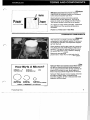
PRODUCTIVITY SERIES HYDRAULICS
Table of Contents – Page 1 of 2
ABOUT THIS MANUAL
SAFETY INFORMATION
INTRODUCTION
WHAT'S IN THIS BOOK?
WHY SHOULD I READ THIS BOOK?
THE BASIC PRINCIPLE OF HYDRAULICS
BENEFITS OF HYDRAULICS
HOW WE USE HYDRAULICS
TERMS AND COMPONENTS
HYDRAULIC TERMS - HYDRAULICS / HYDRODYNAMICS / HYDROSTATICS
WORK
POWER
PRESSURE
FLOW
EFFICIENCY
HYDRAULIC COMPONENTS - RESERVOIR
FILTER
PUMP - FUNCTION
PUMPS - BY TYPE
VALVE--FUNCTION
VALVES--BY NAME
ACTUATOR
ACTUATORS--BY TYPE
REVIEW SECTION #1
UNDERSTANDING CIRCUITS
PROPERTIES OF LIQUIDS
FORCE MAGNIFICATION
BUILDING A BASIC CIRCUIT
BUILDING A LIFT SYSTEM
BUILDING A DRIVE SYSTEM
THE REAL THING
REVIEW SECTION # 2
SPECIFICATIONS
EATON MODEL 7
EATON MODEL 11
EATON MODEL 781
HYDRO-GEAR 316-0500
HYDRO-GEAR 316-0750
PRODUCTIVITY SERIES HYDRAULICS
Table of Contents – Page 2 of 2
SPECIFICATIONS - Continued
HYDRO-GEAR BDP 10
ROSS MF SERIES WHEEL MOTOR
SUNDSTRAND SERIES 15
TUFF TORQ K61A
PROBLEM SOLVING
STEP 1: ASK THE OPERATOR
STEP 2: STUDY THE AVAILABLE INFORMATION
STEP 3: INSPECT THE MACHINE
STEP 4: OPERATE THE MACHINE TO VERIFY
STEP 5: LIST THE POSSIBLE CAUSES
STEP 6: TEST POSSIBLE CAUSES
TEST EQUIPMENT
INLET/OUTLET HOSE
PRESSURE GAUGE
FLOW METER/LOAD VALVE
TEST EQUIPMENT NEEDS
REVIEW SECTION # 3
REVIEW SECTION ANSWERS
REVIEW SECTION # 1
REVIEW SECTION # 2
REVIEW SECTION # 3
ThissymbolmeansWARNINGorManualsandOperator'sManualsareavailablethrough
PERSONAL SAFETY INSTRUCTION your
local Toro distributor or by writing to:
read the instruction becauseit has to
do with your safety. Failure to comply
with the instruction may result
in
The Toro Company
death.
even orpersonal
injury
Publications Department
Aways
read
and
follow
the
safety
instructions
provided
8111
Lyndale
Avenue
South
in applicable
the service
manual
operators
or manual
Bloomington, MN 55420
for the equipment you are working on. Service
Avoid injury from high pressure oil
Avoid Asphyxiation
Never operate an engine
in a confined area without
Keep body and hands away from
pin hole leaks or
nozzles that eject high pressure oil. Use cardboard or proper ventilation.
paper to locate hydraulic leaks. Oil escaping under
high pressure can penetrate the skin and cause injury.Avoid injury from batteries
Oil accidentally injected into the skin must be surgically
removed within a few hours by a doctor familiar with Battery acid is poisonous and can cause burns. Avoid
contact with skin, eyes and clothing. Battery gases can
this form of injury or gangrene may result.
explode. Keep cigarettes, sparks and flames away
from the battery.
Avoid unexpected starting
of engine
Always turn off the engine and disconnect the spark
plug wire(s) before cleaning, adjusting or repairing.
Avoid lacerations and amputations
Avoid injury dueto inferior parts
Use only original equipment parts
to ensure that
important safety criteria are met.
Stay clearof all moving parts whenever the engine
is
running. Treatall normally moving parts as
if they were
moving whenever the engineis running or has the
potential to start.
Always clear the area of bystanders before starting or
testing powered equipment.
Avoid burns
Avoid injury due to projectiles
Avoid injuryto bystanders
of sticks, rocks or any other
Do not touch the engine, muffler, or other components Always clear the area
debris
that
could
be
picked up and thrown by the
which may increasein temperature during operation,
powered
equipment.
while the unitis running or shortly afterit has been
running.
Avoid modifications
Avoid fires and explosions
Never alter or modify any part unless
it is a factory
approved procedure.
Avoid spilling fuel and never
smoke while working with
any type of fuel or lubricant. Wipe up any spilled fuel or
oil immediately. Never remove the fuel cap or add fuel Avoid unsafe operation
when the engine is running. Always use approved,
Always test the safety interlock system after making
labeled containers for storing or transporting fuel and adjustments or repairs on the machine. Refer
to the
lubricants.
electrical chapter later
in this manual for more
information.
INTRODUCTION
In
What’s
Why Should I Read This Book?..............................
3
3
The Basic Principle of Hydraulics ............................
4
Benefits of Hydraulics . . . . . . . . . . . . . . . . . . . . . . . . . . . . . . . . . . . . .
4
...................................
5
How We Use Hydraulics
TERMS AND COMPONENTS
HYDRAULIC TERMS
Hydraulics Hydrodynamics Hydrostatics
.....................
Work . . . . . . . . . . . . . . . . . . . . . . . . . . . . . . . . . . . . . . . . . . . . . . . . . . .
Power. . . . . . . . . . . . . . . . . . . . . . . . . . . . . . . . . . . . . . . . . . . . . . . . . .
Pressure. . . . . . . . . . . . . . . . . . . . . . . . . . . . . . . . . . . . . . . . . . . . . . . .
Flow . . . . . . . . . . . . . . . . . . . . . . . . . . . . . . . . . . . . . . . . . . . . . . . . . . .
Efficiency . . . . . . . . . . . . . . . . . . . . . . . . . . . . . . . . . . . . . . . . . . . . . . .
Function
6
7
7
7
8
HYDRAULIC COMPONENTS
Reservoir . . . . . . . . . . . . . . . . . . . . . . . . . . . . . . . . . . . . . . . . . . . . . . .
8
Filter . . . . . . . . . . . . . . . . . . . . . . . . . . . . . . . . . . . . . . . . . . . . . . . . . . .
8
.........................................
Pumps-ByType . . . . . . . . . . . . . . . . . . . . . . . . . . . . . . . . . . . . . . . . .
Valve-Function . . . . . . . . . . . . . . . . . . . . . . . . . . . . . . . . . . . . . . . . .
.......................................
Valves
Actuator . . . . . . . . . . . . . . . . . . . . . . . . . . . . . . . . . . . . . . . . . . . . . . .
Actuators By Type . . . . . . . . . . . . . . . . . . . . . . . . . . . . . . . . . . . . . .
9
Pump
By
6
REVIEW SECTION
1...................................
9
11
12
14
14
16
UNDERSTANDING CIRCUITS
Properties Of Liquids . . . . . . . . . . . . . . . . . . . . . . . . . . . . . . . . . . . . .
17
ForceMagnification . . . . . . . . . . . . . . . . . . . . . . . . . . . . . . . . . . . . . .
17
Building A Basic Circuit . . . . . . . . . . . . . . . . . . . . . . . . . . . . . . . . . . .
17
....................................
Building A Drive System . . . . . . . . . . . . . . . . . . . . . . . . . . . . . . . . . .
19
21
.........................................
21
Building A Lift System
TheRealThing
Productivity Series
1
.
.
.
.
.
.
REVIEW SECTION# 2 . . . . . . . . . . . . . . . . . . . . . . . . . . . . . . . . . . .
22
SPECIFICATIONS
Eaton Model ...........................................
7
23
EatonModel11 ..........................................
23
EatonModel781 .........................................
Hydro-Gear316.0500 .....................................
24
24
.....................................
Hydro-Gear BDP 10 ......................................
Ross MF Series Wheel Motor
...............................
Sundstrand Series 15 .....................................
Tuff Torq K61A . . . . . . . . . . . . . . . . . . . . . . . . . . . . . . . . . . . . . . . . . .
24
Hydro-Gear316.0750
25
25
25
26
PROBLEM SOLVING
Step 1: Ask The Operator..................................
27
Step 2: Study The Available Information ......................
27
Step 3: Inspect The Machine ...............................
28
Step 4: Operate the Machine to Verify........................
28
Step 5: List The Possible Causes............................
29
..............................
29
Step 6: Test Possible Causes
TEST EQUIPMENT
Inlet/Outlet Hose.........................................
30
PressureGauge......................................... 30
Flow Meter Load Valve ...................................
31
Test Equipment Needs. . . . . . . . . . . . . . . . . . . . . . . . . . . . . . . . . . . .
31
REVIEW SECTION# 3 ...................................
32
............................
33
REVIEW SECTION ANSWERS
Productivity
Series
2
What's In This Book?
This publicationis designed to familiarize the
reader with basic hydraulics.It starts by defining
common terms and components used with
hydraulics. The components are then put
together to show how they function
in a
hydraulic circuit.
Once you are familiar with the basics, the book
will review some of the systems that are used
on Toro(R) equipment. A section on problem
solving covers whatto do when you encounter a
problem. Test equipmentis also reviewed to
ensure you can properly diagnose and repair
hydraulic systems.
RADIAL BALL-PISTON
HYDRAULIC PUMP
VARIABLE DISPLACEMENT
CHAR
PUMP\
HYDRAULIC LIFT CONTROL
VALVE. With 700 PSI RELIEF VALVE
TRANSMISSION CHARGE PRESSURE 30-82 PSI
IMPLEMENT LIFT System PRESSURE 700PSI
For detailed service information on a specific
unit, please referto the appropriate service and
repair manual.
This publication uses a building block approach.
It is necessary to understand the information
in
the front of the bookto better understand
information presented later. Review sections
throughout the book include questions which
involve the key concepts presented.If some
questions are difficultto answer, review the
information again before proceeding.
Answers to the review questions are provided
near the endof the book.
Why Should I Read This Book?
Hydraulics make up an important and expensive
part of many of our products. Mis-diagnosing a
problem causes frustration for you and your
customer, not to mention unnecessary repair
bills.
of hydraulics
Understanding the basic principles
and the components usedin these systems will
improve your ability to properly diagnose and
repair hydraulic systems. The information
presented in this book will give you the basic
fundamentals neededto become an expert in
hydraulics.
3
Productivity Series
The Basic Principleof Hydraulics
Hydraulics referto the useof liquids to transmit
energy. In hydrostatic systems, mechanical
energy from an external source
is converted into
hydraulic pressure. The pressure
is then
transferred through a circuit and re-converted
into mechanical energy.
In our products, the mechanical energy
is
supplied by an engine and the liquid used to
transfer energyis oil.
Benefits of Hydraulics
Let's look atsome of the benefitsof using
hydraulics to transmit power as compared
to a
mechanical system.
Hydrostatic transmissions provide for infinite
variation of output speed.A mechanical
transmission is limited by thenumber of gear
ratios it has.
Hydraulic hoses or lines can be routed
around corners.A mechanical system would
require a complex belt, chain or gear system
to accomplish this.
I
I
The same fluid that transfers the
energy also
provides lubrication for moving parts.
There is a greater need for lubrication
between moving parts under heavy load.
so
With hydraulics, as the load increases,
does the operating pressure. This
automatically provides maximum lubrication
during periodsof higher loads.
Productivity
Series
4
How We Use Hydraulics
Applications for hydraulics are diverse
throughout industry. With lawn and garden
equipment, the main uses are to:
1. Propeltheunit
2. Lift implements attached to the unit
1.1311.19
5
Productivity
The first stepin becoming comfortable with
hydraulics is to learn the language. This section
provides descriptions and examples
of common
hydraulic terms and components.
We will first define some
of the common terms
used when working with hydraulics. Then we
will describe the components which are included
in many of the hydraulic systems you encounter.
of the chapter will
The review section at the end
test your knowledge of the terms and
components.
HYDRAULIC TERMS
Hydraulics Hydrodynamics Hydrostatics
Hydraulics refer to applications of liquids in
motion. Inall of our uses, liquids referto oil.
Hydrodynamics refer to hydraulic systems
which primarily use fluid flow
to transfer energy.
This includes applications such as a water
wheel or a torque converter.
Hydrostatics refer to hydraulic systems which
primarily use fluid pressure to transfer energy.
This includes applications such as a hydraulic
lift system or fluid powered transmission.
All of our applications involve hydrostatics.
Work
Work is the applicationof a force through a
distance. For any work to be accomplished,
movement is needed. Work is typically
measured in foot pounds (ft Ibs).
5 Ibs
Work Force X Distance
Example: The same amount of work
is done if a
5 pound objectis moved 10 feet or if a 10 pound
object is moved 5 feet.
I O Ibs
3.2714
Productivity Series
6
I
HYDRAULIC TERMS (cont’d)
Horsepower
Power
is done or
Power is the rate at which work
energy is transferred. Power is measured in foot
pounds per second(ftlbs/sec).
Power Work Time
One horsepower is equalto 550 ftlbs/sec.
Moving 55 pounds 10 feet in one second takes
one horsepower.
55 Ibs
In hydraulics,to transmit powertwo factors must
be present; pressure and flow.
1 second
Power Pressure X Flow
Pressure
Pressure provides the potential
to transmit
energy. Itis determined by the force across an
area. Pressure is measured in pounds per
square inch (psi).
Pressure Force Area
Ten pounds of force actingon one square inch
provides 10 psi of pressure.
Increasing the load on a hydraulic system will
increase the operating pressure
of the system.
In a hydrostatic transmission, higher pressures
will be generated going uphill as compared to
going downhill.
I
I
3.4297.435
Flow
Flow -measures the transfer rate (velocity) of a
liquid passing through a given cross-sectional
area. Flow is measuredin gallons per minute
(gpm).
Flow Area X Velocity
Flow Volume Time
The flow rate ofa hydraulic system determines
the speed at which the system operates.
Productivity Series
Heat Rise
Efficiency
Efficiency describes the amount of power
output from the hydraulic system as compared
to theamount of power putinto it.
Most hydraulic pumps and motors operate
between 80% to 90% efficiency. The loss of
power is made up by leakage and fluid friction.
This friction causes a heat rise
in the system.
As a pump or motor wears internally,
it becomes
less efficient and the operating temperature
increases.
Power In
Power Out + Heat Rise
HYDRAULIC COMPONENTS
Reservoir
The reservoir is a simple, yet very important
component of any hydraulic system.It serves as
an expansion chamber, and separates trapped
air from the fluid.
Some systems use the gear case as a reservoir.
This allows dirt and metal filings
to settle outof
the fluid. This typeof reservoir allows for more
fluid capacity which in turn assists in keeping
the system properly cooled.
Reservoirs are generally vented and should
prevent dirt or water from entering the system.
How Big Is A Micron?
8 Microns
Red Blood Cell
25 Microns
White Blood Cell
0
Filter IFilter
Hydraulic filters are special purpose filters which
are ableto entrap extremely small particles
of
as
dirt. A typical hydraulic filter will trap particles
small as25 microns or less. Most engine oil
70 microns.
filters only trap particles larger than
Hydraulic filtersdo not have a bypass valve like
an engineoil filter. When a hydraulic filter
becomes clogged, oil flow is reduced and erratic
operation will be evident.
100 Microns
Grain Of Salt
70 Microns
Human Hair
40 Microns
Lower Limit Of Visibility
1 Micron 0.00003937" or 0.001mm
Productivity Series
a
HYDRAULIC COMPONENTS (cont’d)
Pump Function
A pump is a device that transfers fluids by either
suction, pressure or both.A pump converts
mechanical energy into hydraulic pressure and
flow. Pumps can either be fixed or variable
displacement.
HYDRAULIC
A fixed (constant) displacement pump
transfers a set amount of fluid during each
revolution. To change the output, the speed at
which the pump operates must be changed.
A variable displacement pumpcan changeits
output per revolution.
Pumps By Type
of pistons
Axial Pistondesign pumps use a set
rotating in a cylinder block. The cylinder block
is
rotated by the input shaft. The end of the pistons
contact a swashplate. The swashplate may be a
fixed angle (constant displacement) or
adjustable to a range of angles (variable
displacement).
As the cylinder block rotates, the piston (either
pulled by the swashplateor pushed by spring
pressure) extends outof the cylinder block and
draws oil into the chamber. On the opposite
side, the swashplate forces the piston in,
displacing oil from the baseof the cylinder block.
I
3.4297.402
Radial-Ball Pistonpumps use several balls
As the
which travel through bores inside a rotor.
rotor is turned by the input shaft, centrifugal
force throws the balls out against a cam ring.
Oil
from a passage in the pintle flows into the
chamber behind the ball.
With the cam ring offset, the ballis pushed back
into the boreas it rotates past the narrow side.
This forces oil back into a second passage in
the pintle.
The cam ring offset can be either fixed to
provide a constant output, or adjustable to
provide variable output.
9
n
HIGH PRESSURE
OIL OUT
LOW PRESSURE
OIL IN
Productivity Series
An Internal Gear (Gerotor) pump uses two
gears to provide a constant
output of oil per
revolution. The inner gear
is offset from the
pump’s center and is driven by the input shaft.
A
or rotor surrounds
larger internal toothed gear
the inner gear, providing a rotating mesh point
to trap oil.
True internal gear pumps usea crescent seal
which provides a sealing area between both
gears . Gerotor pumps utilize rounded teeth
which do not requirea crescent for sealing.
A Roller Bearingpump isa variation of the
internal gear pump. Insteadof using two gears,
rollers are placed between the teeth
of the
a Constant
driven gear. This also provides
displacement of oil.
1.1311.
External Gear pumps usetwo tightly meshed
gears to producea constant displacement ofoil
per revolution. The input shaft drives one
of the
gears which in turn drives the second gear. The
opposed gear rotation drawsoil from the inlet
port and trapsit between the gear teeth and the
pump body. As the teeth come together near the
oil is forced
outlet port, the area is reduced and
out of the pump.
3.4297.405
Productivity Series
10
HYDRAULIC COMPONENTS(cont'd)
A Charge Pump is a small constant
displacement pump whichis driven by the input
shaft. It provides a base circuit pressure and
flow which can be used for the following
functions:
&
Transferring oil from the reservoirto the
hydrostatic pump
&
4
Pushing oil through a system filter
Supplying oilto remote lift cylinders
-
Valve Function
Valves are usedto provide controlin a hydraulic
system. They can be usedto control:
&
&
&
Pressure
Direction Of Flow
Volume Of
FIOW
We will first review these three functions
of
valves and then review some of the common
types of valves you may encounter.
Pressure Controlvalves may be usedto
provide an upper pressure limit or to maintain a
minimum pressure in a circuit.
For an example, let'slook at a lift system. High
pressure is generated when objects heavier
than the system design are encountered or
when a cylinder reaches the end
of its stroke.
The pressure control (relief) valve opens when
the upper pressure limit of the system
is
reached.
With the valve open, a pressure escape path
routes the oil back into the low pressure side
of
the circuit, protecting the system components
from damage.
3.4297.407
11
Productivity Series
Directional Valvesare usedto control the
direction or pathof fluid flowin a hydraulic
system. This may consist ofa check valve
preventing backflow through a line or a spool
valve diverting the fluid’s path
to a remote
cylinder.
3.4297.4
Flow Control valves are usedto regulate flow
into or out ofa hydraulic component.
With a lift cylinder, a flow control valve can
control the rate at which
oil enters or leaves the
cylinder. This allows the speed at which the
cylinder extends or retracts to
be regulated.
With a transaxle, a flow control valve may
restrict flow through a passage completely
during normal operation, but when activated,
allow oil to pass throughso the unit can be hand
pushed.
3.4297.409
Valves By Name
Acceleration Valve An acceleration valveis a
special flow control valve used
in some
hydrostatic transmissionsto smooth changesin
speed or direction.A common wayto do thisis
by temporarily allowing some
oil to escape from
the high pressure side
to the low pressure side
of the pump/motor circuit.
I
Productivity Series
I
One example of an acceleration valve usesa
small metering hole which slowly allows
high
pressure oil to enter the cavity behind the valve.
As the cavityis filled, the valve advances and
closes the passage between the high and low
pressure circuits.
12
HYDRAULIC COMPONENTS(cont’d)
-
Check Valve A check valve can be used for
pressure control or directional control.
It usually
consists of a ball andseat area. A spring may
be used to hold the ball on the seat.
Some check valves are adjustable. This
is
accomplished by using a spring with a different
rate, shimming the existing spring or
compressing the spring with a threaded adjuster.
I
I
I
3.4297.4111
Push Valve - A push valveis a flow control
valve usedto open a pump/motor circuit.
Manually opening the circuit allows
oil to bypass
from one sideof the circuitto the other or allows
oil toescape back to the reservoir.
The push valve allows the unit to be moved
without starting the engine. Most, but not all
hydrostatic transmissions use a push valve.
3.4297.412
Relief Valve- A relief valveis a pressure
control valve which is used
to protect a hydraulic
circuit from pressures which are higher than the
circuit’s design.
3.4297.413
13
Productivity Series
Spool Valve A spool valveis a directional
valve usedto control oil flow. There aretwo
types of spool valves: open center and closed
center. Both types allowoil flow to be diverted to
a remote circuit when the spool
is not centered.
A closed center spool valve stops
flow from the
pump when it is centered. This typeof valve is
not used with a positive displacement pump.
OPEN
CENTER
An open center spool valve allows
oil from the
pump to pass through the valve when the spool
is centered.
CLOSED
CENTER
3.4297.41
HYDRAULIC
PRESSURE
Actuator
A hydraulic actuatoris a device which converts
hydraulic pressure and flow into mechanical
energy. Thetwo most common types of
actuators are hydrostatic motors and hydraulic
cylinders.
Actuators By Type
A Motor is simply a pump used backwards.It
takes hydraulic pressure and flow from a pump
and converts it back into rotary mechanical
energy.
Due to their similaritiesin function, many motors
use designs similarto pumps. In some cases,
the exact same configuration can be used as a
pump or motor.
Productivity Series
14
HYDRAULIC COMPONENTS (cont’d)
Hydraulic Cylinder A hydraulic cylinder
converts hydraulic pressure and flow into linear
mechanical energy. I t consists of a sealed
chamber, piston, and piston rod. Cylinders can
be either single action or dual action.
CHAMBER
PISTON
PISTON ROD
3.4297.417
Single Action Cylinder Single action
cylinders can only be powered
in one direction.
Gravity or spring pressureis used to retract the
cylinder after extension.
These cylinders comein two different styles.
The typical version has a hydraulic line
connected on one side
of the piston andis
vented to the atmosphere on the opposite side.
A displacement cylinder uses a large shaft
called aram which replaces the piston and
piston rod. It can be serviced externally and
eliminates the need for an atmospheric vent.
3.4297.418
Dual Action Cylinder A dual action cylinder
can be filled with
oil on either sideof the piston.
To extend the piston rod, oil
is forced into the
bottom endof the cylinder and oil ahead
of the
piston is pushed out of the cylinder. During
retraction, this processis reversed, allowing the
piston rod to be powered
in both directions.
r
A typical double action cylinder can exert more
force during extension than it can during
retraction. Thisis because the piston rod takes
away from the piston surfacearea usedto
retract the cylinder.
Force Pressure X Area
I
15
3.4297.419
Productivity Series
1 . In
hydraulic
systems,
.-
energy
from
an
external
source
is converted
into
hydraulic
and flow.
2. As the
load
onhydraulic
a
system
3.
is increased,
the
operating
increases.
refer to hydraulic
systems
which
primarily
use
fluid
pressure
transfer
to energy.
4. Work is the application of a force through a
5.
Power is the
rate
at
which
6. Flow is usually
measured
7. external
An gear
pump
is done
or
energy
in
is a
is transferred.
per
displacement
pump.
8. List the three functions thata valve may perform.
1.
3.
9. A hydraulic actuator converts hydraulic pressure and flow into
powered
beonly
cylinder
1O.A
can
Productivity
in
direction.
one
Series
16
Properties Of Liquids
A liquid has noshape, it always assumes the
shape of its container.
Unlike air, liquids compress only slightly under
pressure.
A force applied to a contained liquid will exert
equal pressurein all directions within the
container.
3.4297.420
Force Magnification
To gain a mechanical
advantage, the sizeof the
ends of the container canbe varied.
Example::The pump hasan area of 1 square
10 square
inch. The cylinder has an area of
inches. If 10 pounds of force is applied to the
pump, 100 pounds of forceis exerted on the
cylinder.
If the amount of work putinto the system equals
the amount of work outof the system[I00%
efficient], the pump will travel
10 times farther
than the cylinder.
3.4297.421
Building A Basic Circuit
Let’s put together a simple circuit using some
basic hydraulic components. We will start out
with a simple pump and cylinder connected by a
line.
As you can see,there aresome flaws in this
design. There is not extra
oil so that the pump
can continue raising the cylinder after the first
stroke. Also, when the pump handle is raised,
the cylinder drops.
3.4297.422
17
Productivity Series
The flaws can be corrected by installing a
reservoir and two check valves. One check
valve will keep oil from being forced back into
the reservoir and the second will keep oil
the
under the cylinder when the pump handle
is
raised.
When the pump armis raised, the surface area
of the chamber between the check valves
increases. As the area increases, pressure
acting on the surfaces inside the chamber
decreases. When the pressurein the reservoir
becomes greater than the spring pressure on
the check valve and the pressure
in the
chamber; the check valve movesoff its seat.
As oil flows into the chamber, the pressure
begins to increase. As the handle is pushed
downward, the pressure inside the chamber
increases and closes the check ball under the
reservoir.
The second check ball now opens allowing the
oil to flow into the chamber under the cylinder
ram.
3.4297.424
The force neededto extend the cylinder ram
is
dependent on the amount of weight on the ram.
A five pound weight requires five pounds
of
of the
force to lift. Because the size (area)
cylinder can not be changed, adding more
weight to the cylinder requires a higher pressure
to achieve movement.
When the pump reaches the end
of its stroke,
pressure under the pump and cylinder
equalizes, allowing the check valve
to close and
trapping the oil under the cylinder.
3.4297.425
Productivity Series
18
Building A Basic Circuit (Cont’d)
This cycleis repeated until the cylinder ram
is
fully extended. Notice in the simplifiedsystem,
To accomplish this,
the ram can not be let down.
we need to add a second valve under the
cylinder. This valve should not open unless the
pressure capacityof the systemis met or it is
A
manually opened to let the cylinder ram down.
return line will direct the
oil from the cylinder
back to the reservoir.
3.4297.426
Building A Lift System
Let’s replace the hand pump with an external
gear pump whichis capable of providing
constant displacement and more flow.
By placing thepump in-line, we no longer need
the check valves to provide directional control.
The greater output of this pump will extend the
cylinder much faster. When the cylinder ram
reaches the endof its stroke, pressure will
increase and open the relief valve.
3.4297.427
If we replace the single action cylinder with an
open center spool valve and a dual action
cylinder, we have a basiclift system.
When the spool valveis centered, the oil passes
directly through it and returns to the reservoir.
3.4297.428
19
Productivity Series
When the spool valveis offset, oil is directed
into the bottom end
of the cylinder and the
piston rodis extended. Notice thatoil from the
opposite sideof the piston also passes through
the spool valve and back
to the reservoir.
I
3.4297.4:29
When the pressurein the cylinder reaches the
setting of the pressure relief valve,
the valve
opens and directs the
oil flow backto the
reservoir. This happens when a high resistance
is met, such as the cylinder reaching the end of
its”stroke.
I
I
3.4297.430
When the spool valveis offset in the opposite
direction, theoil flow through the valve and
cylinder is reversed.
I
I
3.4297.431
Productivity
Series
20
Building ASystem
Drive
Let’s replace the cylinder with another type of
actuator a fixed displacement hydraulic motor.
With the motorin place, this system will provide
the continuous mechanical energy output
needed to propel lawn and garden equipment.
This system can reverse the direction
of travel
by changing the spool offset and reversing the
oil flow through the motor. Notice that there
is
nothing in this system that will allow the output
speed to be changed.
Our hydrostatic drive systems use a variable
displacement pump and a fixed displacement
motor.
With variable output from the pump, the spool
valve is no longer needed to control the
direction of oil flow. The speed can also be
changed with this variable output pump.
3.4297.433
The Real Thing
If we combine the drive system with the
lift
system we had previously, the resultis a
hydraulic system similar to systems on many
of
the larger tractors in use today.
I
Productivity Series
1. Under load, which pressure gauge(A or B) below will indicate the most pressure?
2. If both circuits below have the same amountof pressure applied to them, which circuit(A or B) is capable
of lifting more weight?
3. Which valve (A, B or C) in the circuit below is responsible for protecting the system from high pressure?
Productivity
Series
22
We use several different hydraulic systems
across our product line. Allof these systems are
made from the basic components described
earlier and operateby using the fundamental
principles of hydraulics.
Eaton Model 7
This hydrostatic transmission has a variable
radial-ball pistonpump and fixed displacement
radial-ball motor.Maximum pump outputis
0.465 cu. in.(7.62cc) per revolution. The motor
output is 0.767 cu.in (12.57 cc) per revolution.It
does not use a charge pump. A fine screen at
the bottomof the reservoir provides for filtration
of incoming oil. This unit must
be coupled to a
final drive to provide power
to the drive wheels.
1.1311.2
Eaton Model11
The Eaton 11is similar to the model7 but is
considerably larger and uses an auxiliary charge
pump. The pump displacesa maximum of 1.15
cu.in.(18.85cc) per revolution and the motor
has a 2.09 cu. in. (34.25 cc) displacement per
revolution. The charge pump supplies a
maximum flow of 1.5 gpm (5.7l/min) [0.10cu.
in. per revolution (1.6cchev)] and can provide
power for a hydraulic attachment lift. This
system is used with a separate filter and
reservoir. Again, this unit must be coupled to a
final driveto power the drive wheels.
1.1311
23
Productivity Series
Eaton Model 781
This transaxleis used as a pair(RH & LH) to
make up a complete drive system.
It has a
variable radial-ball pistonpump and fixed
displacement radial-ball motor. Maximum pump
output is 0.465 cu.in.(7.62cc) per revolution.
The motor outputis 0.767 cu. in. (12.57 cc) per
A
revolution. It does not use a charge pump.
remote expansion tankis used for a reservoir
with a fine screen at the bottom
of the inlet line
providing the filtrationof incoming oil. Two sets
of planetary reduction gears provide power
to
the axle.
1.1311.3
Hydro-Gear 316-0500
This is a typical hydrostatic transaxle used
in a
lawn tractor It is completely self-contained and
has its own differential. This transaxle utilizes a
variable axial piston pump with a maximum
displacement of 0.61 cu. in. (10 cc) per
revolution. The motoris also an axial piston
design with a fixed displacement
of 1.28 cu. in.
(21 cc) per revolution.
1.1311.5
Hydro-Gear 316-0750
This hydrostatic transaxleis similar to the
316-0500. It uses a heavier differential
to handle
higher loads. This transaxle utilizes a variable
axial piston pump with maximum
a
displacement
of 0.61 cu. in. (10 cc) per revolution. The motor
is also an axial piston design with a fixed
displacement of 1.28 cu. in. (21 cc) per
revolution.
1.1311.6
Productivity Series
24
Hydro-Gear BDP 10
This pump is a variable output axial piston
design with a maximum output of 0.61 cu. in.
(10 cc) per revolution. This pump uses a gerotor
charge pump to pre-charge the system.
This is usedin a separated pump and wheel
motor system. Hydraulic lines connect the pump
with a wheel motor.
Ross MF Series Wheel Motor
The Ross wheel motor is an internal gear
(gerotor) design. The displacementis 12 cu.
in./rev (196.7cc/rev. A separate pumpis used
to provide the pressure and flow
to this motor.
A small displacement pump is used
to drive the
wheel motor. The pump must complete several
revolutions to displace enough oilto drive the
wheel motor through one revolution. This
provides a speed reduction similar to using
reduction gears in a mechanical transmission.
1.1311.111. 31 .1
Sundstrand Series15
The Sundstrand Series 15 uses an axial piston
variable pump with a fixed displacement axial
piston motor. The maximum pump output
is
.91cu. in. (14.9 cc) per revolution and the motor
displacement is .91cu. in. (14.9 cc) per
revolution. An internal gear (gerotor) charge
pump provides 4.6 gal/min(17.4l/min). [.33cu.
in. per revolution (5.4cchev)] flow for use with a
hydraulic attachment lift.
1.1311.8
25
Productivity Series
Tuff Torq K61A
This transaxleis completely self-contained andhas its own differential. It utilizes a variable axial
a fixed displacement axial
piston pump and with
piston'motor.
An internal spring assists in returning the control
arm to neutral. A dampening pistonis used on
the motion control input arm to smooth
directional changes.
1.1311.7
Productivity Series
26
Using a systematic approach makes hydraulic
troubleshooting easy. By following a process
which narrows down the possible causes, a
problem can be pinpointed and confirmed.
Step 1 : Ask the Operator
Step 2: Study the Available Information
Step 3: Inspect the Machine
Step 4: Operate the Machine to Verify Problem
Step 5: List the Possible Causes
Step 6: Test Possible Causes
Step 1:Ask The Operator
A detailed problem description
is a valuable
diagnostic tool during troubleshooting.
Has there been oilloss from the system?
What type of terrain (slope) was the product
used on?
How was the unit being used?
How warm was the fluid?
What type of maintenance has been performed?
Did anything unusual happen before the
problem occurred?
Example Complaint
Lift system doesn’t work. Can not
get the deck to raise.
Problem Description
Hasn’t noticed oilloss.
Used on fairly flat
yard for mowing
only.
Same operationif hydro cold or
warm.
Use 5 seasons - never serviced
Answers to these questions should be recorded
on the work order.
Step 2: Study The Available Information
Review the technical information which applies
to the hydraulic system you are working with.
Flow diagrams will show which types of
components are involvedin the system.
Can the problem be related
to a particular circuit
or partof a circuit?Does the problem seemto
be pressure related? Does the problem seem to
be relatedto oil flow? What components are
controlling these conditions?
Circuit Involves
Charge Pump
Spool Valve
Lift Cylinder
Filter
Lines & Fittings
Control Linkage forspool valve
Be sure to check for Service Bulletins which
may apply to this system.
27
Productivity Series
Inspection Results
Oil is fairly clean- no signs of
water or overheating
Spool valve works smooth
Hydro is clean
Hoses appear in good shape
Does not apply- unit drives great
so the problemis in thelift circuit.
Drive operationOK
Engine runsOK.
Lift system does not work. Seems
like it tries to raise deck.
Noisy when spool valveis off
center.
Step 3: Inspect The Machine
Its now timeto collect physicalevidence. Again,
take notes on what you see.
Inspect the the oilin the unit.
Is the oil level correct?
Does it look
black(Dirt)? Does it look milky (Water)? Does
it smell burnt( Overheated)? Are there
bubbles in the reservoir (Airleak)?
Inspect the outsideof the hydraulic system.
Does the control linkage work properly?
Does it have full travel?Is it secure? Is there
debris around the hydraulic components?
Are thehoses/lineskinked? Are there any
signs of leakage?
Inspect the drive, for the system.
look normal? Are
Does the input drive line
there signsof slippage in the system?
.
Inspect the output drive
Does everything seem secure? Are the drive
keys in place? Can you push the unit without
activating the push valve?
Step 4: Operate the Machine to
VerifyIf the machinestill operates, use the detailed
problem descriptionto verify what the operator
experienced. Use circumstances similar
to those
provided in the problem description to reproduce
the problem.
While operating the unit, note anything that may
affect the hydraulic systems operation. How well
does the engine run? Do the brakes work
properly? Are there any belts slipping?
Do the
controls work smoothly? Does the system
operate properlyin one direction and not the
other?
Be sure to record all your observations.
Productivity Series
2%
Step 5: List The Possible Causes
Make a listof the possible causes for this
problem. Use your notes to support your
conclusions.
Which causes best match the description of the
be easily verified?
problem? Which causes can
Step 6: Test Possible Causes
Using the technical information and the proper
test equipment, test the possible causes to
verify your conclusions. Start with the items on
your list which are the easiest to check.
If it is not be possible to pinpoint the problem to
one component, an internal inspection will be
necessary.
29
Possible Causes
Charge pump failing- low output
Internal cylinder leakage
Spool valve problem
Hose kinked
Relief valve problem
Spool valve linkage
Check The Easy ThingsFirst
Hose kinked easy
Spool valve linkageeasy
Charge pump failing - low output
Relief valve problem
Internal cylinder leakage
Spool valve problem
Productivity
-
To properly troubleshoot many hydraulic
systems, it is necessary to measure the
pressure andor flow at various pointsin the
system. This can only be done by using the
proper test equipment.
if there
Service and repair manuals will indicate
are specific tests which can be performed aon
specific hydraulic system. The amount
of
pressure andor flow the system should be
generating will determine the size and type of
the equipment needed.
Inlet/OutletHose
Hoses are used to connect your test
equipment'
into the system you are testing. The hoses
should be rated higher than any pressure that
may be reached during testing. They should
also be long enough to allow
for easy readingof
be
the test equipment. Adapter fittings may
needed to attach to different systems.
1.1311.14
Pressure Gauge
As you might expect, pressure gauges are used
to measure the pressures experienced during
certain phasesof circuit operation.
A good quality pressure gaugeis usually liquid
filled to stabilize the needle.
Low pressure
0 to
gauges for hydraulic testing will read from
1000 psi (70.3 kg/sq cm). A high pressure
0 and
gauge normally allows for testing between
5000 psi (351.3 kg/sq cm).
1.1311.15
Productivity Series
30
Flow Meter Load Valve
Flow Meters are usedto measure the actual
flow in a circuit during operation. The meter
is
placed inline and will indicate flow
in gallons per
minute (gpm).
A Load Valveis a flow control valve which can
be used during testingto simulate a load.As the
flow is restricted, a higher loadis simulated.
Load valves are usually used
in combination
with a flow meter.
1.1311.16
Test Equipment Needs
The type of test equipment you need depends
on the typeof equipment being servicedin your
shop. Generally, test gauges can be adapted
to
many different systems simply by using adapter
fittings. Your test equipment should be capable
of handling pressures greater than the pressure
generated by the largest system you will need
to
test.
1.1311.20
A liquid filledgauge capable of 1000 psi (70.3
kg/sq cm) will be sufficient for testing hydraulic
systems on TORO Wheel Horse riding products.
Some systems used onTORO ProLine
equipment require a flow meter capable
of
measuring at least7 GPM. A high pressure
gauge may also be needed. When performinga
traction teston a ProLine 220, pressuresin
excess of 4000 psi (281 kg/sq cm) will be
experienced.
31
I
Product
Pressure
Gauge
High
Pressure
Gauge
Flow Meter
Load Valve
Tractors
Lawn
ProLine
Mid-Size
ProLine 100
Productivity Series
1. The first step in problem solving is to:
A. Study the available information
B. List the possible causes
C. Inspect the machine
D. Ask the operator
E. Operate the machine to verify the problem
2. Oil which looks milkyis most likely contaminated with:
A. Milk
8. Dirt
C. Water
D. Transmissionfluid
E. Nothing
3. An indicator of an overheated hydraulic system is:
A. Burnt smelling fluid
B. Oil loss in the system
C. Loss of power as the system warms
D. Air bubbles in the reservoir
E. Black colored oil
4. Whentestingthepossiblecausesofahydraulicsystemproblem,alwaystestthepossibilities
first.
5. Whenusingaloadvalveduringtesting,asflow
6. Thetestequipmentused
is restricted,ahigher
is simulated.
in yourshopshouldbecapableofhandlingthegeneratedbythe
largest hydraulic system you will need
to test.
Productivity
Series
32
Review Section 1
1. mechanical,pressure
2. pressure
3. Hydrostatics
4. distance
5. work
6. gallons,minute
7. fixedconstant
8. Pressure Control, DirectionOf Flow, Volume Of Flow
9. mechanicalenergy
10.single action
Review Section# 2
1. Both gauges will read the same amount
of pressure because they arein the same circuit.
2. Circuit A - Force is equal to pressure times the area on which
it is acting. The pressure is the same in
both circuits. The cylinder
in circuit A is larger than the cylinderin circuit The same pressure times a
larger area will generate the most force.
3. Valve C - Valve A is a check valve which keeps oils from returning
to the reservoir during pumping. Valve
B keeps the oil trapped under the
lift cylinder. Valve Cis used as a pressure relief valve and as a flow
control valve to let the cylinder down.
Review Section 3
1. D
2. c
3. A
4. easy
5. load
6. pressures
f-
This Productivity Series Manual was written as a training guide for service technicians. Learning the fundamentals
of a subject is a necessary step
in becoming an expertin any area. This publicationis designed to increase the
readers knowledge on hydraulics. The
Toro Company has made every effort to make
the informationin this
manual complete and correct.
We are hopeful that you will find this manual a valuable addition
to your service shop.If you have any questions
or comments regarding this manual, please contact us at the following address:
The Toro Company
Consumer Service Training Department
8111 Lyndale Ave. S.
Bloomington, MN 55420
The Toro Company reserves the rightto change product specifications or this manual without notice.
Copyright@All Rights Reserved
994 The Toro Company