1
TABLE OF CONTENTS
Specifications ………………………………………………………………………………………
General safety rules………………………………………………………………………………...
Additional safety rules for miter saws ……………………………………………………………...
Know your product …………………………………………………………………………………
Operation and adjustments ………………………………………………………………………….
Unpacking …………………………………………………………………………………
Transportation ……………………………………………………………………………..
Bench mounting …………………………………………………………………………...
Release knob ………………………………………………………………………………
Slide lock ………………………………………………………………………………….
Miter table lock ……………………………………………………………………………
Bevel lock …………………………………………………………………………………
Hold down clamp assembly ……………………………………………………………….
Spindle lock button ………………………………………………………………………..
Rotating lower blade guard ………………………………………………………………..
Dust collection bag ………………………………………………………………………..
Attaching the material support arms ………………………………………………………
Trench depth adjustment …………………………………………………………………..
Turning on and off ………………………………………………………………………..
Setting the table square with the blade ……………………………………………………
Setting the fence square with the table ……………………………………………………
Changing a blade ………………………………………………………………………….
Cross-cutting (without slide action) ………………………………………………………
Cross-cutting (with slide action) ………………………………………………………….
Bevel cut …………………………………………………………………………………..
Compound miter cut ………………………………………………………………………
Maintenance ………………………………………………………………………………………..
Power cord maintenance ………………………………………………………………….
Cleaning …………………………………………………………………………………..
General inspection ………………………………………………………………………..
Exploded view and parts list ……………………………………………………………………….
Limited two years warranty…………………………………………………………………………
3
4
6
7
8
8
8
8
8
8
8
9
9
9
9
9
9
10
10
10
11
11
11
12
12
13
15
15
15
15
16
20
WARNINGS
It may be more difficult to see the laser line in conditions of bright sunshine and on certain surfaces.
For safe operation read instruction manual.
2 Specifications
Model Number
Input Power
No Load Speed
Blade Size
Number of teeth
MiterTable Angles
Bevel Cuts
Weight
70716
120V, 60Hz, 15A
5500 RPM
10" x 5/8" bore
60
0° to 52° Left & Right
0° to 45° Left only
29.7 lbs
Cutting Capacity
Straight cut
Miter cut
Bevel cut
Compound miter cut
at 0° miter, 0° bevel: 3-1/4x11-/5/8"
at 45° miter, 0° bevel: 3-1/4x8-1/16"
at 0° miter, 45° left bevel: 1-5/8x11-5/8"
at 45° left miter, 45° left bevel: 1-5/8x8-1/16"
The WEN 10" Sliding Compound Miter Sawis supplied with the following accessories as standard:
• Saw blade (installed)
• Hold down clamp
• 6 mm hex key
• 2 material support arms
• Dust collection bag
• Instruction manual
3 General safety rules
WARNING:Read all safety warnings and instructions. Failure to follow the warnings and instructions
may result in electric shock, fire and/or serious injury.
Save all warnings and instructions for future reference.
The term “power tool” in the warnings refers to your operated (corded) power tool.
1.
Work area safety
a.
b.
c.
2.
Electrical safety
a.
b.
c.
d.
e.
f.
3.
Keep work area clean and well lit. Cluttered or dark areas invite accidents.
Do not operate power tools in explosive atmospheres, such as in the presence of flammable liquids, gases
or dust. Power tools create sparks that may ignite the dust or fumes.
Keep children and bystanders away while operating a power tool. Distractions can cause you to lose
control.
Power tool plugs must match the outlet. Never modify the plug in any way. Do not use any adapter plugs
with earthed (grounded) power tools. Unmodified plugs and matching outlets will reduce risk of electric
shock.
Avoid body contact with earthed or grounded surfaces, such as pipes, radiators, ranges and refrigerators.
There is an increased risk of electric shock if your body is earthed or grounded.
Do not expose power tools to rain or wet conditions. Water entering a power tool will increase the risk of
electric shock.
Do not abuse the cord. Never use the cord for carrying, pulling or unplugging the power tool. Keep cord
away from heat, oil, sharp edges or moving parts. Damaged or entangled cords increase the risk of electric
shock.
When operating a power tool outdoors, use an extension cord suitable for outdoor use. Use of a cord
suitable for outdoors reduces the risk of electric shock.
To reduce the risk of electric shock, the manufacturer recommends using a residual current device with a
rated residual current of 30mA or less at all times.
Personal safety
a.
b.
c.
d.
e.
f.
g.
Stay alert, watch what you are doing and use common sense when operating a power tool. Do not use a
power tool while you are tired or under the influence of drugs, alcohol or medication. A moment of
inattention while operating power tools can result in serious personal injury.
Use personal protective equipment. Always wear eye protection. Protective equipment such as dust mask,
non-skid safety shoes, hard hat, or hearing protection used for appropriate conditions will reduce personal
injuries.
Prevent unintentional starting. Ensure the switch is in the off-position before plugging in, picking up or
carrying the tool. Carrying power tools with your finger on the switch or plugging in power tools that
have the switch on invites accidents.
Remove any adjusting key or wrench before turning the power tool on. A wrench or a key left attached to
a rotating part of the power tool may result in personal injury.
Do not overreach. Keep proper footing and balance at all times. This enables better control of the power
tool in unexpected situations.
Dress properly. Do not wear loose clothing or jewelry. Keep your hair, clothing and gloves away from
moving parts. Loose clothes, jewelry or long hair can be caught in moving parts.
If devices are provided for the connection of dust extraction and collection facilities, ensure these are
connected and properly used. Use of dust collection can reduce dust-related hazards.
4 4.
Power tool use and care
a.
b.
c.
d.
e.
f.
g.
h.
i.
5.
Do not force the power tool. Use the correct power tool for your application. The correct power tool will
do the job better and safer at the rate for which it was designed.
Do not use the power tool if the switch does not turn it on and off. Any power tool that cannot be
controlled with the switch is dangerous and must be repaired.
Disconnect the plug from the power source and from the power tool before making any adjustments,
changing accessories, or storing power tools. Such preventive safety measures reduce the risk of starting
the power tool accidentally.
Store idle power tools out of the reach of children. Do not allow anyone unfamiliar with the power
tool/instructions to operate the power tool. Power tools are dangerous in the hands of untrained users.
Maintain power tools. Check for misalignment or binding of moving parts, breakage of parts and any
other condition that may affect the power tool’s operation. If damaged, have the power tool repaired
before use. Many accidents are caused by poorly maintained power tools.
Keep cutting tools sharp and clean. Properly maintained cutting tools with sharp edges are less likely to
bind and easier to control.
Use the power tool, accessories, tool bits, and etcetera, in accordance with these instructions. Take into
account the working conditions and the work to be performed. Use of the power tool for operations
different from those intended can result in a hazardous situation.
This appliance is not intended for use by persons (including children) with reduced physical, sensory or
mental capabilities, or lack of experience and knowledge, unless they have been given supervision or
instruction concerning use of the appliance by a person responsible for their safety.
Children should be supervised to ensure that they do not play with the appliance.
Service
Have your power tool serviced by a qualified repairperson using only identical replacement parts. This will ensure
that the safety of the power tool is maintained.
5 Additional safety rules for miter saws
•
•
•
•
•
•
•
•
•
•
•
•
•
•
•
•
•
•
•
•
•
•
•
•
•
•
•
Ensure that the lighting is adequate.
Do not use the saw unless the guards are in place.
Do not use the saw to cut metal or masonry.
Keep the area free of tripping hazards.
Do not let anyone under 18 years operate this saw.
Always stand to one side when operating the saw.
Never use damaged or deformed saw blades. Only use sharp blades.
When cutting round wood, use clamps that prevent the workpiece from turning on both sides of the blade.
Never use your hands to remove sawdust, chips or waste from near the saw blade.
Only use blades as recommended by the manufacturer.
Do not use blades manufactured from high-speed steel.
If the table insert is damaged or worn, have it replaced by an authorized service center.
Before making compound miter cuts, ensure that the work head is securely fixed in the desired position.
Rags, cloths, cord, string and the like should never be left around the work area.
Avoid cutting nails. Inspect the workpiece and remove all nails and other foreign objects before beginning to
saw.
Support the work properly.
Never reach over the blade to remove waste or cut-offs.
Do not attempt to free a jammed blade while the machine is still running.
Do not slow or stop a blade with a piece of wood. Let the blade come to rest naturally.
If you’re interrupted during operation, complete the task at hand and turn the saw off before looking up.
Periodically check that all nuts, bolts and other fastenersare properly tightened.
Always hold the saw by the insulated parts. If you accidentally cut into hidden wiring or the saw’s own cable,
the metal parts of the saw will become electrified. Turn off and unplug immediately.
Connect the saw to a dust collection device that is operating properly.
Wear gloves when handling saw blades.
Keep the floor area around the machine level, well maintained and free of loose materials such as wood chips
and cut-offs.
During slide cutting, always push the saw blade awayas opposed to pulling it back towards you.
Always use stands to provide support for pieces that extend past the worktable.
WARNING:We recommend the use of a Ground-Fault Circuit Interrupter (GFCI).
Wear goggles
Wear earmuffs
Wear a breathing mask
WARNING! For your own safety read instruction manual before operating miter saw. Wear eye
protection. Keep hands out of path of saw blade. Do not operate saw without guards in place. Do not
perform any operation freehand. Never reach around the saw blade. Turn off tool and wait for saw blade to stop
before moving workpiece or changing settings. When changing the blade, replace and secure all guarding to its
original and correct position before starting tool. Disconnect power before changing blade or servicing the power
tool. Do not expose to rain. Do not use in damp locations. To reduce the risk of injury, return carriage to the full
rear position after each crosscut operation.
The tool must be used only for its prescribed purpose. Any use other than those mentioned in this manual will be
considered a case of misuse. The user shall be liable for any damage or injury resulting from such cases of misuse.
The manufacturer shall not be liable for any changes made to the tool nor for any damage resulting from such
changes.
Even when the tool is used as prescribed it is not possible to eliminate all residual risk factors. The following
hazards may arise in connection with the tool’s construction and design:
• Damage to the lungs if an effective dust mask is not worn.
• Damage to hearing if effective earmuffs are not worn.
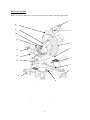
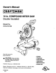
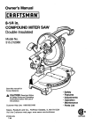
6 Know your product
Before using the saw, familiarize yourself with all the operating features and safety requirements.
1 16 15 2 14 13 3 4 12 11 5 10 6 7 9 8 1. Operating Handle
2. ON/OFF Switch
3. Blade Guard
4. Fence
5. Miter Table
6. Table Insert
7. Miter Lock
8. Miter Scale
9. Support Arm
10. Clamp Assembly
11. Bevel Lock Knob
12. Slide Bar
13. Slide Lock knob
14. Dust Extraction Port
15. Guard Retraction Arm
16. Carrying Handle
7 Operation and adjustments
Unpacking
Due to modern mass production techniques, it is unlikely that your WEN® tool is faulty or that a part is missing.
However,if you find anything wrong, do not operate the tool until the parts have been replaced or the fault has
been rectified. Failure to do so could result in serious personal injury.
1. Remove all loose parts from the carton.
2. Remove the packing materials from around the saw.
3. Using the carrying handle (16) carefully lift the saw from the carton and place it on a level work surface.
4. The saw has been shipped with the saw arm locked in the down position. To release the saw arm, push down
on the top of the saw arm, pull on the release knob (Fig. 2), rotate it 45° and let go, slowly raise the saw arm.
WARNING: Do not lift the saw while holding on to the guards. Use the carrying handle (16).
Transportation
Lift the miter saw only when the saw arm is locked in the down position, the saw is switched off and the plug is
removed from the power source.
Only lift the saw by the carrying handle (16) or outer castings. Do not lift the saw using the guard or operating
handle (1).
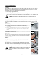
Fig. 1 Bench mounting
The saw base has holes in each corner to facilitate bench mounting (Fig. 1).
1. Mount and fix the saw to a level, horizontal bench or worktable using four bolts
(not included).
2. If desired, you can mount the saw to a piece of 1/2" or thicker plywood which
can then be clamped to your work support or moved to other job sites and reclamped.
CAUTION: Make sure that the mounting surface is not warped. Uneven surfaces can
cause binding and inaccurate sawing.
Fig. 2 Release knob
The release knob is provided for holding the cutting head down while transporting or
storing the miter saw (Fig. 2). The saw must never be used while the release knob is
locking the head down.
Slide lock
When tightened, the slide lock knob(Fig. 3) prevents the saw head from sliding.
Tighten the slide lock knobduring transportation.
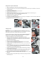
Fig. 3 Miter table lock
The miter table lock (7) is used to lock the table at the desired miter angle (Fig. 4).
The miter saw cuts from 0° to 45° both left and right. To adjust the angle, loosen the
miter table lock and rotate to the desired miter angle. Relock the table in place. The
miter table features positive click stops at 0°, 15°, 22.5°, 30° and 45° for quick setting
of common miter angles.
WARNING: Be sure to tighten the miter table lock before making a cut.
Failure to do so cancause the table to move during the cut, resulting in
serious personal injury.
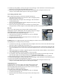
8 Fig. 4 Bevel lock
The bevel lock (11) is used to set the blade at the desired bevel angle (Fig. 5). The miter saw bevels from 0° to 45°
left.
WARNING: Be sure to tighten the bevel lock before making a cut. Failure to do so could result in the
saw arm moving during the cut and cause serious personal injury.
Fig. 6 Hold down clamp assembly
The hold down clamp assembly can be mounted to the fence on either side of the saw
bladedepending onwhat suits the task at hand.Use the clamp assembly lock at the back of the
fence to secure the clamp assembly in position (Fig. 6).
Note: use only ONE clamp at a time.
Fig. 7 Spindle lock button
The spindle lock button prevents the blade in the saw from rotating (Fig. 7). Depress and hold the
spindle lock button while installing, changing or removing the blade.
Rotating lower blade guard
The rotating lower blade guard provides protection from both sides of the blade (Fig. 8).
It retracts over the upper blade guard as the saw is lowered onto the workpiece.
Fig. 8 Dust collection bag
The dust collection bag fits over the dust extraction port (14). For more efficient operation,
empty the dust bag when it is half full. This allows better air flow through the bag.
Attaching the material support arms
Fig. 9
The material support arms help to support the materialwhen working
with longworkpieces. There are two location holes for asupport bar on
either side ofthe table. Loosen the lock screws with the 6mmhex key.
Ensure the sidebarsare fully inserted before usingthem to support the
workpiece(Fig. 9 & 10).
The side support bar locking screws must be tightenedto secure the
support bars inposition (Fig. 9 & 10).
9 Fig. 10
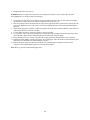
Trench depth adjustment
In its normal position, the trenching stop permits the saw blade to cut right through a workpiece. When the saw
arm is lifted, the trenching stop can be moved to the left so that the trenching depth adjustment screw contacts the
stop as the saw arm is lowered. (Fig.11).This restricts the cut to a specific “trench” in the workpiece. The depth of
the trench can be adjusted with the trenching depth adjustment screw (Fig. 12) and locked in position with the
trenching depth lock nut(Fig. 13).
Fig. 11 Fig. 12 Fig. 13
Fig. 14 Turning on and off
1.
2.
Pull in switch trigger to startthe unit (Fig. 14).
To turn the saw off releasethe ON/OFF trigger switch.
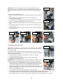
Setting the table square with the blade
Fig. 15
1.
2.
Make sure that the power cord is removed from the power source.
Push the saw arm down to its lowest position and engage the release knob(Fig. 2)
to hold the saw arm in the transport position.
3. Loosen the miter lock(Fig. 15).
4. Rotate the table until the pointer is positioned at 0º.
5. Tighten the miter lock (Fig. 15).
6. Loosen the bevel lock (Fig. 16) and set the saw arm at 0º bevel (leaving the blade
at 90º to the miter table). Tighten the bevel lock (Fig. 16).
7. Place a set square against the table and the flat partof the blade (Fig. 17).
Note. Make sure that the square contacts the flat part ofthe saw blade, not the teeth.
8. Rotate the blade by hand and check the blade-to-tablealignment at several points.
9. The edge of the set square and the saw blade shouldbe parallel.
10. If the saw blade angles away from the set square,adjust as follows.
11. Use a 13mm wrench or adjustable wrench to loosen thelock nut securing the
0°bevel adjustment screw(Fig. 18). Also, loosenthe bevel lock (Fig. 16).
12. Adjust the 0° bevel adjustment screw ( Fig. 18) with the 6mm hex key to bring the
saw blade into alignment with the square (Fig. 19)
13. Loosen the 2 screws holding the pointer of the bevel scale and adjust the position
of the pointer so that it accurately indicates zero on the scale (Fig. 20). Retighten
the screw.
14. Retighten the bevel lock (Fig. 16) and the lock nut securing the 0° bevel
adjustment screw (Fig. 16).
Note. The above procedure can also be used to check theangle of the saw blade to the
table at the 45º bevel angle.
Fig. 18 Fig. 19 Fig. 20
10 Fig. 16
Fig. 17
Setting the fence square with the table
1.
2.
Make sure that the power cord is removed from the power source.
Push the saw arm down to its lowest position and engage the release knob (Fig. 24) to hold the saw arm in the
transport position.
3. Loosen the miter lock (Fig. 15).
4. Rotate the table until the pointer is positioned at 0º.
5. Tighten the miter lock (Fig. 15).
6. Using the 6mm hex key provided, loosen the four screws securing the fence to the base (Fig. 21).
7. Place a square against the fence and alongside the blade (Fig. 22).
8. Adjust the fence until it is square with the blade.
9. Tighten the screws securing the fence.
10. Loosen the screw holding the pointer of the miter scale (Fig. 23) and adjust it so that it accurately indicates the
zero position on the miter scale (Fig. 23).
11. Retighten the screw securing the miter scale pointer.
Fig. 21 Fig. 22
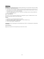
Changing a blade
Fig. 23 Fig. 24 DANGER! Never try to use a blade larger than the statedcapacity of the saw. It
might come into contact with theblade guards. Never use a blade that is too thick to
allow theouter blade washer to engage with the flats on the spindle.
It will prevent the blade screw from properly securing the blade on the spindle. Do
not use the saw to cut metal or masonry. Ensure that any spacers and spindle
ringsthat may be required suit the fitted spindle and blade.
1. Make sure that the power cord is removed from the power source.
2. Push down on the operating handle (1) and pull the release knob (Fig. 24) to
disengage the saw arm. The release knob (Fig. 24) can be turned so that it is
held in the retracted position.
3. Raise the saw arm to its highest position.
4. Using a screwdriver loosen and remove the screw that secures the guard
retraction arm to the rotating blade guard (Fig. 25).
5. Using a screwdriver loosen and remove the screw that secures the arbor bolt
cover (Fig. 26).
6. Pull the rotating blade guard down then swing it up together with the arbor
bolt cover. When the rotating blade guard is positioned in the upward position,
it is possible to access the arbor bolt (Fig. 27).
7. Hold the rotating guard up and press the spindle lock button (Fig. 28). Rotate
the blade until the spindle locks.
8. Use the 6mm hex key provided to loosen and remove the arbor bolt (loosen in a
clockwise direction as the blade screw has a left-handed thread) (Fig. 29).
9. Remove the flat washer, the outer flange washer and the blade.
10. Wipe a drop of oil onto the inner flange and the outer flange where they contact
the blade.
11. Fit the new blade onto the spindle taking care that the inner flange sits behind
the blade (Fig. 30).
11 Fig. 25 Fig. 26 CAUTION:To ensure correctblade rotation, always installthe blade with the
bladeteeth and the arrow printedon the side of the bladepointing downwards. The
direction of the blade’s rotation is alsostamped with an arrow on the upper blade
guard.
12. Replace the outer flange (Fig. 31).
13. Depress the spindle lock button (Fig. 28) and replace the flat washer and arbor
bolt.
14. Use the 6mm hex key to tighten the arbor bolt securely (tighten in a
counterclockwise direction).
15. After lowering the blade guard, hold the rotating lower blade guard and arbor
bolt cover in position and tighten the fixing screw (Fig. 32).
16. Replace the guard retraction arm and secure onto the rotating blade guard (Fig.
25).
17. Check that the blade guard operates correctly and covers the blade as the saw
arm is lowered.
18. Connect the saw to the power source and run the blade to make certain that it is
operating correctly.
Fig. 29 Fig. 30 Fig. 31
Fig. 27 Fig. 28 Fig. 32 Cross-cutting (without slide action)
Fig. 33 When cutting a narrow piece of wood, it is not necessary touse the slide mechanism.
In these cases, ensure that theslide lock knob(13) is screwed down to prevent the
saw armfrom sliding.
A crosscut is made by cuttingacross the grain of theworkpiece. A 90º crosscut
ismade with the miter table setat 0º (Fig. 33). Miter crosscutsare made with the table
set atsome angle other than zero.
1. Pull on the release knob (Fig. 24) and lift the saw arm to its full height.
2. Loosen the miter lock (Fig. 15).
3. Rotate the miter table until the pointer aligns with the desired angle.
4. Retighten the miter lock (Fig. 15).
WARNING: Be sure to tighten the miter lock before makinga cut. Failure to do so
Fig. 34 could result in the table movingduring the cut and cause serious personal injury.
5. Place the workpiece flat on the table with one edge securely against the fence.
If the board is warped, place the convex side against the fence. If the concave
side is placed against the fence, the board could break and jam the blade.
6. When cutting long pieces of timber, support the opposite end of the timber with
either the side support arms, a roller stand, a work surface level with the saw’s
table or a combination of the three.
7. Use the clamp assembly to secure the workpiece wherever possible.
8. It is possible to remove the clamp assembly by loosening the clamp assembly lock and moving it to the other
side of the table. Make sure the clamp assembly lock is tight before using the clamp (Fig. 34).
9. Before turning on the saw, perform a dry run of the cutting operation to check that there are no problems.
12 10. Hold the operating handle (1) firmly and squeeze the switch trigger. Allow the blade to reach maximum speed
and slowly lower the blade into and through the workpiece.
11. Release the switch trigger and allow the saw blade to stop rotating before raising the blade out of the
workpiece. Wait until the blade stops before removing the workpiece.
Cross-cutting (with slide action)
Fig. 35 When cutting wideworkpieces, first unscrew theslide lock knob(13).
1. Pull on the release knob (Fig. 24), raise the saw arm to its highest position
and slide it towards you (Fig. 35).
2. Hold the handle firmly and squeeze the switch trigger. Allow the blade to
reach maximum speed.
3. Slowly lower the blade into the workpiece and push it away from you at the
same time until the workpiece is cut.
4. Release the switch trigger and allow the saw blade to stop rotating before
raising the blade out of the workpiece. Wait until the blade stops before removing the workpiece.
Bevel cut
A bevel cut is made bycutting across the grain ofthe workpiece with the
bladeangled to the fence and mitertable. The miter table is setat the zero degree
positionand the blade set at an anglebetween 0º and 45º (Fig. 36).
Use the slide action when cutting wide workpieces.
1. Pull on the release knob (Fig. 24) and lift the saw arm to its full height.
2. Loosen the miter lock (Fig. 15).
3. Rotate the miter table until the pointer aligns with zero on the miter scale.
4. Retighten the miter lock (Fig. 15).
Fig. 36
WARNING: Be sure to tighten the miter lock before makinga cut. Failure to do so could result in the table
movingduring the cut, causing serious personal injury.
5.
6.
7.
8.
9.
10.
11.
12.
13.
Loosen the bevel lock (Fig. 16) and pull out the 0º bevel adjuster. Move the saw arm to the desired bevel angle
(between 0º and 45º). Tighten the bevel lock (Fig. 16).
Place the workpiece flat on the table with one edge securely against the fence. If the board is warped, place the
convex side against the fence. If the concave side is placed against the fence, the board could breakand jam the
blade.
When cutting long pieces of timber, support the opposite end of the timber with the sidebars, a roller stand or a
work surface that is level with the saw table.
Use the clamp assembly to secure the workpiece wherever possible.
It is possible to remove the clamp assembly by loosening the clamp assembly lock and movingit to the other
side of the table. Make sure the clamp assembly lock is tight before using the clamp.
Before turning on the saw, perform a dry run of the cutting operation to check that there are no problems.
Hold the operating handle (1) firmly and squeeze the switch trigger. Allow the blade to reach maximum speed.
Slowly lower the blade into and through the workpiece.
Release the switch trigger and allow the saw blade to stop rotating before raising the blade out of the
workpiece. Wait until the blade stops before removing the workpiece.
Compound miter cut
A compound miter cut involves using a miter angle anda bevel angle at the
sametime (Fig. 37). It is used to make picture frames, cutmoldings, make
boxeswith sloping sides and frame roofs. Always make a testcut on a piece of
scrap woodbefore cutting into goodmaterial.
Use the slide action when cutting wide workpieces.
1. Pull on the release knob (Fig. 24) and lift the saw arm to its full height.
2. Loosen the miter lock (Fig. 15).
3. Rotate the miter table until the pointer aligns with the desired angle on the
miter scale.
13 Fig. 37 4.
Retighten the miter lock (Fig. 15).
WARNING: Be sure to tighten the miter lock before makinga cut. Failure to do so could result in the table
movingduring the cut, causing serious personal injury.
5.
Loosen the bevel lock (Fig. 16) and pull out the 0º bevel adjuster and move the saw arm to the left or right to
the desired bevel angle (between 0º and 45º). Tighten the bevel lock (Fig. 16).
6. Place the workpiece flat on the table with one edge securely against the fence. If the board is warped, place the
convex side against the fence. If the concave side is placed against the fence, the board could break and jam
the blade.
7. When cutting long pieces of timber, support the opposite end of the timber with the sidebars, a roller stand or a
work surface that is level with the saw table.
8. Use the clamp assembly to secure the workpiece wherever possible.
9. It is possible to remove the clamp assembly by loosening the clamp assembly lock and moving it to the other
side of the table. Make sure the clamp assembly lock is tight before using the clamp.
10. Before turning on the saw, perform a dry run of the cutting operation to check that there are no problems.
11. Hold the operating handle (1) firmly and squeeze the switch trigger. Allow the blade to reach maximum speed
and slowly lower the blade onto and through the workpiece.
12. Release the switch trigger and allow the saw blade to stop rotating before raising the blade out of the
workpiece. Wait until the blade stops before removing the workpiece.
Note: Wear eye protection when brushing dust away.
14 Maintenance
WARNING: Always ensure that the tool is switched off and the plug is removed from the outlet before making
any adjustments or maintenance procedures.
• Any damage to this tool should be repaired and carefully inspected by qualified repair personnel before use.
• Have your power tool serviced by a qualified repairperson using only identical replacement parts. This will
ensure that the safety of the power tool is maintained.
• Great Lakes Technologies, LLC will not be responsible for any damage or injury caused by unauthorized
repair or mishandling of the tool.
Power cord maintenance
If the supply cord needs replacing, the manufacturer, the manufacturer’s agent, or an authorized service centre
must carry out the task in order to avoid a safety hazard.
Cleaning
1.
2.
3.
4.
Keep the tool’s air vents unclogged and clean at all times.
Remove dust and dirt regularly. Cleaning is best done with a soft brush or a rag.
Re-lubricate all moving parts at regular intervals.
Never use caustic agents to clean plastic parts.
CAUTION: Do not use cleaning agents to clean the plastic parts of the saw. A mild detergent on a damp cloth is
recommended.
General inspection
Regularly check that all screws are tight. They may vibrate loose over time.
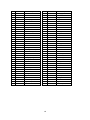
15 Exploded view and parts list
16 17 Item
1
2
3
4
5
6
7
8
9
10
11
12
13
14
15
16
17
18
19
20
21
22
23
24
25
26
27
28
29
32
33
34
35
36
37
38
Stock #
70716-001
70716-002
70716-003
70716-004
70716-005
70716-006
70716-007
70716-008
70716-009
70716-010
70716-011
70716-012
70716-013
70716-014
70716-015
70716-016
70716-017
70716-018
70716-019
70716-020
70716-021
70716-022
70716-023
70716-024
70716-025
70716-026
70716-027
70716-028
70716-029
70716-032
70716-033
70716-034
70716-035
70716-036
70716-037
70716-038
Description
Screw
Motor cover
Screw
Brush spring
Brush hold
Carbon brush
Screw
Spring washer
Washer
Motor housing
Rubber boot
Wave washer
Bearing
Armature
Stator
Fan baffle
Screw
Bearing
Anti-finger touch plate
Lock washer
Screw
E clip
Lock pin spring
Lock pin
Screw
Nut
Lower handle
Cord clamp
Power cord
Screw
Cord protector
Upper handle
Screw
Lower carry handle
Upper carry handle
Screw
Item
39
40
42
43
45
46
47
48
49
50
51
52
53
54
55
56
57
58
59
60
61
62
63
64
65-76
77
78
79
80
81
82
83
84
85
86
87
18 Stock #
70716-039
70716-040
70716-042
70716-043
70716-045
70716-046
70716-047
70716-048
70716-049
70716-050
70716-051
70716-052
70716-053
70716-054
70716-055
70716-056
70716-057
70716-058
70716-059
70716-060
70716-061
70716-062
70716-063
70716-064
70716-065
70716-077
70716-078
70716-079
70716-080
70716-081
70716-082
70716-083
70716-084
70716-085
70716-086
70716-087
Description
Binding post
Screw
Trigger
Trigger switch
Adjust knob
Nut
Screw
Nut
Saw arm
Bearing
C clip
Gear
Washer
Key
Spindle
Bearing
Screw
Washer
Cover
Screw
Inner flange
Blade
Outer flange
Arbor bolt
Blade guard assembly
Screw
Guard retraction arm
Shoulder Screw
Screw
Wave washer
Bracket
Rubber pole
Spring washer
Screw
Big screw
Trench depth bracket
Item
88
89
90
97
98
99
100
101
102
103
104
105
106
107
108
109
110
111
112
113
114
115
116
117
118
119
120
121
122
123
124
125
126
127
128
129
130
131
132
Stock #
70716-088
70716-089
70716-090
70716-097
70716-098
70716-099
70716-100
70716-101
70716-102
70716-103
70716-104
70716-105
70716-106
70716-107
70716-108
70716-109
70716-110
70716-111
70716-112
70716-113
70716-114
70716-115
70716-116
70716-117
70716-118
70716-119
70716-120
70716-121
70716-122
70716-123
70716-124
70716-125
70716-126
70716-127
70716-128
70716-129
70716-130
70716-131
70716-132
Description
Rolled pin
Pivot shaft
Bracket cap
Screw
Spring washer
Lock pin
Rolled pin
Lock pin spring
Release knob
Big torsion spring
Spring sleeve
Screw
Bearing cover
Screw
Slide lock knob
Glide bearing
Bearing set
Slide end cap
Spring washer
Screw
Slide bar
Linear bearing
Spring loop
Screw
Bevel lock knob
Bevel lock bolt
Washer
Locknut
Washer
Arm
Nut
Screw
Bevel pointer
Screw
Double stud
Safety cover
Screw
Screw
Screw
Item
133
134
135
136
137
138
139
140
141
142
143
144
145
146
147
148
149
150
151
152
153
154
155
156
157
158
159
160
161
162
163
164
165
166
167
168
169
170
171
Stock #
70716-133
70716-134
70716-135
70716-136
70716-137
70716-138
70716-139
70716-140
70716-141
70716-142
70716-143
70716-144
70716-145
70716-146
70716-147
70716-148
70716-149
70716-150
70716-151
70716-152
70716-153
70716-154
70716-155
70716-156
70716-157
70716-158
70716-159
70716-160
70716-161
70716-162
70716-163
70716-164
70716-165
70716-166
70716-167
70716-168
70716-169
70716-170
70716-171
19 Description
Spring
Roll
Locknut
Washer
Miter table
Screw
Table insert
Miter scale pointer
Screw
Rolled pin
Lock boot
Lock bolt
Miter lock
Screw
Turntable bolt
Turntable bolt cover
Screw
Detent plate
Screw
Screw
Safety foot
Support arm
Base
Rubber foot
Nameplate rivet
Miter scale
Spring washer
Screw
Bolt knurled
Screw
Clamp
Workpiece knob
Knob
Clamp arm
Support pole
Screw
Washer
Fence
Dust collection bag
Limited two years warranty
WEN® Products is committed to build tools that are dependable for years. Our warranties are consistent with this commitment
and our dedication to quality
LIMITED WARRANTY OF WEN® CONSUMER POWER TOOLS PRODUCTS FOR HOME USE
GREAT LAKES TECHNOLOGIES, LLC ("Seller") warrants to the original purchaser only, that all WEN® consumer power
tools will be free from defects in material or workmanship for a period of two (2) years from date of purchase. Ninety days for
all WEN® products, if the tool is used for professional use.
SELLER'S SOLE OBLIGATION AND YOUR EXCLUSIVE REMEDY under this Limited Warranty and, to the extent
permitted by law, any warranty or condition implied by law, shall be the repair or replacement of parts, without charge, which
are defective in material or workmanship and which have not been misused, carelessly handled, or misrepaired by persons other
than Seller or Authorized Service Center. To make a claim under this Limited Warranty, please contact us at 1-800-232-1195 or
write to us at WEN® Products, 1675 Holmes Road, Elgin, IL 60123. To acquire service, you will have to provide proof of
purchase and may be asked to ship the tool back to us freight prepaid.
THIS LIMITED WARRANTY DOES NOT APPLY TO CIRCULAR SAW BLADES AND MOTOR BRUSHES.
ANY IMPLIED WARRANTIES SHALL BE LIMITED IN DURATION TO TWO (2) YEARS FROM DATE OF
PURCHASE. SOME STATES IN THE U.S., SOME CANADIAN PROVINCES DO NOT ALLOW LIMITATIONS ON
HOW LONG AN IMPLIED WARRANTY LASTS, SO THE ABOVE LIMITATION MAY NOT APPLY TO YOU.
IN NO EVENT SHALL SELLER BE LIABLE FOR ANY INCIDENTAL OR CONSEQUENTIAL DAMAGES
(INCLUDING BUT NOT LIMITED TO LIABILITY FOR LOSS OF PROFITS) ARISING FROM THE SALE OR USE OF
THIS PRODUCT. SOME STATES IN THE U.S. AND SOME CANADIAN PROVINCES DO NOT ALLOW THE
EXCLUSION OR LIMITATION OF INCIDENTAL OR CONSEQUENTIAL DAMAGES, SO THE ABOVE LIMITATION
OR EXCLUSION MAY NOT APPLY TO YOU.
THIS LIMITED WARRANTY GIVES YOU SPECIFIC LEGAL RIGHTS, AND YOU MAY ALSO HAVE OTHER RIGHTS
WHICH VARY FROM STATE TO STATE IN THE U.S., PROVINCE TO PROVINCE IN CANADA AND FROM
COUNTRY TO COUNTRY.
THIS LIMITED WARRANTY APPLIES ONLY TO PORTABLE ELECTRIC TOOLS, BENCH POWER TOOLS,
OUTDOOR POWER EQUIPMENT AND PNUMATIC TOOLS SOLD WITHIN THE UNITED STATES OF AMERICA,
CANADA AND THE COMMONWEALTH OF PUERTO RICO. FOR WARRANTY COVERAGE WITHIN OTHER
COUNTRIES, CONTACT THE WEN® CUSTOMER SUPPORT.
20