1
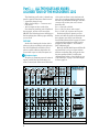
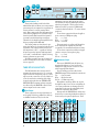
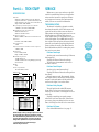
MICROSERIES1202 OWNER’S MANUAL
MIC 1
MIC 2
MIC 3
RIGHT
LEFT/MONO
MIC 4
1
L
1
L
MICRO SERIES 1202
12-CHANNEL MIC/LINE MIXER
2
2
STEREO AUX RETURNS
40dB
–10
+4
U
GAIN
TRIM 1
40dB
–10
TRIM 2
U
40dB
+15
TRIM 3
L
MONO
+15
L
MONO
L
MONO
MONO
+15
R
R
R
GAIN
TRIM 4
LINE 5-6
LINE 7-8
LINE 9-10
LINE 11-12
U
U
U
U
U
1
OO
U
MAIN OUTS
40dB
U
1
OO
U
TAPE
OUTPUT
–10
+4
U
GAIN
U
1
OO
+4
U
GAIN
TAPE
INPUT
VITY
TI
R
+4
U
R
BAL/UNBAL
VITY
TI
SEN
SI
SEN
SI
–10
L
LINE 4
LINE 3
BAL/UNBAL
VITY
TI
SEN
SI
LINE 2
BAL/UNBAL
VITY
TI
SEN
SI
LINE 1
BAL/UNBAL
AUX OUT
R
1
OO
U
+15
1
OO
U
+15
1
OO
U
+15
U
1
OO
U
+15
PHONES
1
OO
U
1
+15
OO
U
+20
U
TAPE IN
AUX 2
2
OO
+15
2
OO
AUX
+15
2
OO
AUX
+15
2
OO
AUX
+15
2
OO
AUX
+15
2
OO
AUX
+15
2
OO
AUX
+15
2
OO
AUX
2
+15
OO
AUX
+20
STEREO AUX RETURN TO MASTER
+22
CLIP
TRIM LINE IN
1-4
1-12
+10
HI
–15 +15
HI
–15 +15
HI
–15 +15
HI
–15 +15
HI
–15 +15
HI
–15 +15
HI
–15 +15
HI
INPUT CH.
METERING
+7
–15 +15
+4
+2
LO
LO
LO
LO
LO
LO
LO
0
LO
–15 +15
–15 +15
–15 +15
–15 +15
–15 +15
–15 +15
–15 +15
–15 +15
EQ
EQ
EQ
EQ
EQ
EQ
EQ
EQ
POWER
0dBu
CAL.
-2
-4
-7
-10
L
OO
R
L
R
L
R
L
R
L
R
L
R
L
R
L
R
PAN
PAN
PAN
PAN
PAN
PAN
PAN
PAN
U
U
U
U
U
U
U
U
+20
GAIN 1
OO
+20
GAIN 2
OO
+20
GAIN 3
OO
+20
GAIN 4
OO
+20
GAIN 5-6
OO
+20
GAIN 7-8
OO
+20
GAIN 9-10
OO
-20
-30
U
BAL.
+20
U
OO
GAIN 11-12
+10
MASTER
1
OO
PHONES
CAUTION
AVIS
RISK OF ELECTRIC SHOCK
DO NOT OPEN
RISQUE DE CHOC ELECTRIQUE
NE PAS OUVRIR
CAUTION: TO REDUCE THE RISK OF ELECTRIC SHOCK
DO NOT REMOVE COVER (OR BACK)
NO USER-SERVICEABLE PARTS INSIDE
REFER SERVICING TO QUALIFIED PERSONNEL
ATTENTION: POUR EVITER LES RISQUES DE CHOC
ELECTRIQUE, NE PAS ENLEVER LE COUVERCLE. AUCUN
ENTRETIEN DE PIECES INTERIEURES PAR L'USAGER. CONFIER
L'ENTRETIEN AU PERSONNEL QUALIFIE.
AVIS: POUR EVITER LES RISQUES D'INCENDIE OU
D'ELECTROCUTION, N'EXPOSEZ PAS CET ARTICLE
A LA PLUIE OU A L'HUMIDITE
The lightning flash with arrowhead symbol within an equilateral
triangle is intended to alert the user to the presence of uninsulated
"dangerous voltage" within the product's enclosure, that may be
of sufficient magnitude to constitute a risk of electric shock to persons.
Le symbole éclair avec point de flèche à l'intérieur d'un triangle
équilatéral est utilisé pour alerter l'utilisateur de la présence à
l'intérieur du coffret de "voltage dangereux" non isolé d'ampleur
suffisante pour constituer un risque d'éléctrocution.
The exclamation point within an equilateral triangle is intended to
alert the user of the presence of important operating and maintenance
(servicing) instructions in the literature accompanying the appliance.
Le point d'exclamation à l'intérieur d'un triangle équilatéral est
employé pour alerter les utilisateurs de la présence d'instructions
importantes pour le fonctionnement et l'entretien (service) dans le
livret d'instruction accompagnant l'appareil.
8. Power Cord Protection — Power supply cords should be
routed so that they are not likely to be walked upon or
pinched by items placed upon or against them, paying
particular attention to cords at plugs, convenience receptacles,
and the point where they exit the MicroSeries 1202.
9. Object and Liquid Entry — Care should be taken so that
objects do not fall into and liquids are not spilled into the
inside of the MicroSeries 1202.
10. Damage Requiring Service — The MicroSeries 1202
should be serviced only by qualified service personnel when:
A. The power-supply cord or the plug has been
damaged; or
B. Objects have fallen, or liquid has spilled into the
MicroSeries 1202; or
C. The MicroSeries 1202 has been exposed to rain; or
D. The MicroSeries 1202 does not appear to operate
normally or exhibits a marked change in performance; or
E. The MicroSeries 1202 has been dropped, or its
chassis damaged.
11. Servicing — The user should not attempt to service the
MicroSeries 1202 beyond those means described in this
operating manual. All other servicing should be referred to the
Mackie Service Department.
12. To prevent electric shock, do not use this polarized plug
with an extension cord, receptacle or other outlet unless the
blades can be fully inserted to prevent blade exposure.
SAFETY INSTRUCTIONS
1. Read Instructions — All the safety and operation instructions
should be read before the MicroSeries 1202 is operated.
2. Retain Instructions — The safety and operating
instructions should be kept for future reference.
3. Heed Warnings — All warnings on the MicroSeries 1202
and in these operating instructions should be followed.
4. Follow Instructions — All operating and other instructions
should be followed.
5. Water and Moisture — The MicroSeries 1202 should not
be used near water—for example, near a bathtub,
washbowl, kitchen sink, laundry tub, in a wet basement, near
a swimming pool, swamp or salivating St. Bernard dog, etc.
6. Heat — The MicroSeries 1202 should be situated away
from heat sources such as radiators, or other devices which
produce heat.
7. Power Sources — The MicroSeries 1202 should be
connected to a power supply only of the type described in these
operation instructions or as marked on the MicroSeries 1202.
V 2.4 –1/95
2
Pour préevenir les chocs électriques ne pas utiliser cette fiche
polariseé avec un prolongateur, un prise de courant ou une
autre sortie de courant, sauf si les lames peuvent être insérées
à fond sans laisser aucune pariie à découvert.
13. Grounding or Polarization — Precautions should be
taken so that the grounding or polarization means of the
MicroSeries 1202 is not defeated.
14.This apparatus does not exceed the Class A/Class B
(whichever is applicable) limits for radio noise emissions from
digital apparatus as set out in the radio interference
regulations of the Canadian Department of Communications.
ATTENTION —Le présent appareil numérique n’émet pas de
bruits radioélectriques dépassant las limites applicables aux
appareils numériques de class A/de class B (selon le cas)
prescrites dans le règlement sur le brouillage radioélectrique
édicté par les ministere des communications du Canada.
WARNING — To reduce the risk of fire or electric shock, do
not expose this appliance to rain or moisture.
PATCHBAY DESCRIPTION
BEGINS ON PG. 4
PATCH
BAY
CHANNEL STRIP & OUTPUT
SECTION DESCRIPTION, PG. 8
1202
CONTROLS
CONNECTION TIPS &
HOOK-UP , PG. 11
HOOK
UP
DETAILED LEVEL-SETTING
PROCEDURE, PG. 12
LEVEL
SETTING
STEPS
1202 BLOCK DIAGRAM
& SERVICE INFO PG. 13-15
Fast-Track “CAN’T WAIT!” tips
for people who ignore manuals
A. To adjust input levels:
1.
2.
3.
4.
5.
Set TRIM fully counterclockwise.
Set GAIN to unity (twelve o’clock).
Push in the INPUT CH. METERING switch.
Feed a normal signal into a selected input.
Adjust that input’s TRIM control so that
the display on the left LED strip stays
around 0, and never goes higher than +10.
6. Repeat for each of Channels 1– 4.
B. Connecting effects
Read the section starting on page 11 for
full information on connecting digital delays,
reverbs, etc. via AUX SENDS and STEREO
AUX RETURNS. This can get pretty complicated quickly.
Don’t cream your monitor speakers
INTRODUCTION
Thank you! There are a lot of makes and
models out there, all competing for your
bucks … but you have voted with your wallet
for the folks in Woodinville who specialize in
American-made mixers.
There are only two other things we ask:
First, now that you’ve got a MicroSeries
1202, find out how to get the most from it.
That’s where this manual comes in.
• If this is your first pro mixer, flip through
the whole book: you’ll find it full of actual
from-the-streets engineering tips, as well
as operation and installation instructions.
• If you’re an experienced, big-bucks
engineer with lots of fader hours under
your fingertips, at least read “Part 1: All
the Holes and Knobs.” (We’ve found that
experienced engineers usually read
manuals cover-to-cover anyway so that
they can keep getting the big bucks.)
Always turn the master gain and headphone level controls down before making
connections to and from your MS 1202.
3
TECH
STUFF
Part 1 — ALL THE HOLES AND KNOBS:
A GUIDED TOUR OF THE MICROSERIES 1202
The first thing you’ll notice is that the top
panel is organized into three distinct areas:
• A patchbay along the top;
• Eight channel strips — four mono and
four stereo;
• And an output section on the right.
Note that four patchbay jacks overflowed
the top panel, and are on the rear of the
MS 1202. The following pictures will help you
find everything; the next few pages will help
you use it all.
of circuit is excellent at rejecting hum and
noise. You can plug any kind of professional
mic that has a standard “XLR-type” male mic
connector. If you wire your own, connect
them like this:
Pin 1 = Ground or shield
Pin 2 = Hot (in phase with output)
Pin 3 = Cold (out of phase with output)
Professional ribbon, dynamic and condenser mics will all sound excellent through
these inputs, especially if you follow the
Level Setting instructions on page 12. Lowercost electret-type unbalanced mics can be
plugged into Line Inputs 1–12, but will require additional gain.
Basically, the MS 1202’s inputs will handle
any kind of mic level you can toss at them
without overloading. But you’ll get the absolute best quality sound if you follow the
calibration procedure covered briefly in our
“Can’t Wait Tips” on page 3, and more depth
in Part 3, page 12.
PATCHBAY
At the risk of stating the obvious, this is
where you plug everything in: microphones,
line-level instruments and effects, headphones, and the ultimate destination for
your sound: a tape recorder, PA system, etc.
1 Microphone Inputs
We use true “phantom-powered, balanced
inputs” just like the big studio mega-consoles, for exactly the same reason: this kind
MIC 1
MIC 2
MIC 3
RIGHT
LEFT/MONO
MIC 4
1
L
1
L
MICRO SERIES 1202
12-CHANNEL MIC/LINE MIXER
2
2
STEREO AUX RETURNS
–10
L
LINE 4
40dB
+4
U
GAIN
TRIM 1
40dB
–10
TRIM 2
U
40dB
+15
TRIM 3
L
MONO
+15
L
MONO
L
MONO
MONO
+15
R
R
R
GAIN
TRIM 4
LINE 5-6
LINE 7-8
LINE 9-10
LINE 11-12
U
U
U
U
U
1
OO
U
MAIN OUTS
40dB
U
1
OO
U
TAPE
OUTPUT
–10
+4
U
GAIN
U
1
OO
+4
U
GAIN
TAPE
INPUT
VITY
TI
R
+4
U
R
BAL/UNBAL
VITY
TI
SEN
SI
SEN
SI
–10
PATCHBAY
LINE 3
BAL/UNBAL
VITY
TI
SEN
SI
LINE 2
BAL/UNBAL
VITY
TI
SEN
SI
LINE 1
BAL/UNBAL
AUX OUT
R
1
OO
U
+15
1
OO
U
+15
1
OO
U
+15
U
1
OO
U
+15
PHONES
1
OO
U
1
+15
OO
U
+20
U
TAPE IN
AUX 2
2
OO
+15
2
OO
AUX
+15
2
OO
AUX
+15
2
OO
AUX
+15
2
OO
AUX
+15
2
OO
AUX
+15
2
OO
AUX
+15
2
OO
AUX
2
+15
OO
AUX
+20
STEREO AUX RETURN TO MASTER
+22
CLIP
TRIM LINE IN
1-4
1-12
+10
HI
–15 +15
HI
–15 +15
HI
HI
HI
CHANNEL STRIPS
–15 +15
LO
HI
–15 +15
LO
–15 +15
LO
–15 +15
LO
HI
–15 +15
HI
INPUT CH.
METERING
+7
–15 +15
+4
+2
LO
LO
LO
0
LO
–15 +15
–15 +15
–15 +15
–15 +15
–15 +15
–15 +15
–15 +15
–15 +15
EQ
EQ
EQ
EQ
EQ
EQ
EQ
EQ
POWER
0dBu
CAL
-2
OUTPUT
-4
-7
-10
L
OO
R
L
L
R
L
R
L
R
L
R
L
R
L
R
PAN
PAN
PAN
PAN
PAN
PAN
PAN
PAN
U
U
U
U
U
U
U
U
+20
GAIN 1
4
R
OO
+20
GAIN 2
OO
+20
GAIN 3
OO
+20
GAIN 4
OO
+20
GAIN 5-6
OO
+20
GAIN 7-8
OO
+20
GAIN 9-10
OO
-20
-30
U
BAL.
+20
GAIN 11-12
U
OO
+10
MASTER
OO
PHONES
MIC 1
1
MIC 2
MIC 3
RIGHT
LEFT/MONO
MIC 4
1
L
5
2
2
STEREO AUX RETURNS
2
BAL/UNBAL
40dB
GAIN
TRIM 1
VITY
TI
SEN
SI
–10
+4
U
LINE 3
BAL/UNBAL
VITY
TI
SEN
SI
VITY
TI
–10
+4
U
40dB
3
GAIN
TRIM 2
L
LINE 4
–10
40dB
GAIN
TRIM 3
MAIN OUTS
L
L
MONO
4
–10
+4
U
TAPE
OUTPUT
MONO
R
+4
U
TAPE
INPUT
L
MONO
VITY
TI
R
R
AUX SEND
BAL/UNBAL
SEN
SI
BAL/UNBAL
LINE 2
SEN
SI
LINE 1
L
1
R
MONO
R
R
40dB
GAIN
TRIM 4
Microphone Power
LINE 5-6
LINE 7-8
LINE 9-10
LINE 11-12
Line inputs 1–4 are a good place to connect older keyboards which have low gain, or
keyboards in general since you can adjust
the corresponding channel TRIM control so
that the mixer has plenty of gain but you can
keep the keyboard volume control set
around the halfway mark.
Most modern professional condenser mics
are equipped for Phantom Power, which lets
the mixer send low-voltage DC to the mic’s
electronics over the same wires that carry
audio. (Semi-pro condenser mics often have
batteries to accomplish the same thing.) The
“Phantom” owes its name to an ability to be
3 Trim controls
“unseen” by dynamic mics which don’t need
TRIM 1 through 4 adjusts the input sensiexternal power and aren’t affected by it anytivity of the mic and line inputs connected to
way. NOTE: Do not apply phantom power to
Channels 1 through 4. This allows signals from
ribbon microphones, or you will have an
the proverbial outside world to be brought in
entertaining fireworks display.
at optimal internal operating levels. See Level
The MS 1202’s phantom power is controlled
Setting instructions on page 12.
by the PHANTOM switch on the rear panel.
4 Chs. 5–6, 7–8, 9–10, 11–12 Line Inputs
2 Ch. 1–4 Line Inputs
These four line inputs share circuitry (but
not phantom power) with the mic preamps,
and can be driven by balanced or unbalanced
devices at almost any level. In other words,
you can use these inputs for virtually any signal you’ll come across, from instrument levels
to levels of –10 to +4, since there is 40dB
more gain available than on Channels 5–12.
tip
ring
shield
sleeve
cuff
hem
garter belt
(ground)
positive
(white wire)
negative
(black wire)
To connect these inputs to balanced
sources, use a Tip-Ring-Sleeve (TRS) or
three-conductor plug (the type found on stereo headphones):
Tip
= Positive (+ or hot)
Ring = Negative (– or cold)
Sleeve = Shield or ground
To connect the inputs to unbalanced
sources, use a mono phone plug or standard
instrument cable. The jack on the MS 1202
will sense the plug and disable the balancing
circuits.
These inputs are designed for stereo or
mono unbalanced signals from –10dBV to
+4dBu. They can be used with just about any
professional or semi-pro instrument, effect,
or tape player. In the audio world, an oddnumbered channel usually receives the “left
signal”. For example, feed line inputs 5–6 a
stereo signal by inserting the device’s left
output plug into the Channel 5 jack, and its
right output plug into the Channel 6 jack.
5 STEREO AUX RETURNS to Master
This is where you connect the outputs of
your effects devices. The STEREO AUX
RETURNS are wired identically to the stereo
line inputs. The circuits will handle stereo or
mono unbalanced signals, either instrument
level, –10dBV or +4dBu. They can be used
with just about any pro or semi-pro effect on
the market.
Additional information on connecting
effects to the MS 1202 starts on page 11.
5
PATCH
BAY
11
13 14
ON
ON
CAUTION
12-CHANNEL MIC/LINE MIXER
DIRECT OUT WITH NO SIGNAL
INTERRUPTION TO MASTER
POWER
6
CAUTION: TO REDUCE THE RISK OF ELECTRICAL SHOCK,
DO NOT REMOVE BOTTOM COVER. NO USER-SERVICEABLE
PARTS INSIDE. REFER SERVICING TO QUALIFIED PERSONNEL
RISK OF ELECTRIC SHOCK
DO NOT OPEN
MICRO SERIES 1202
CONCEIVED, DESIGNED, AND MANUFACTURED BY MACKIE DESIGNS INC. • WOODINVILLE WASHINGTON
DIRECT OUT WITH SIGNAL
INTERRUPTION TO MASTER
FOR USE AS AN EFFECTS LOOP
(TIP = SEND, RING = RETURN)
PHANTOM
48V
12
MONO PLUG
MONO PLUG
INSERT ONLY INTO THE
"FIRST CLICK"
SERIAL NUMBER
MADE IN USA
CHANNEL INSERTS
4
3
2
1
STEREO PLUG
INSERT ALL THE WAY IN TO
THE "SECOND CLICK"
6 Channel Inserts 1–4
TIP OUT TO EFFECTS DEVICE
RING RETURN FROM EFFECTS
impedance and can drive as low as a 600Ω
line. Balanced output is 6dB higher than for
unbalanced outputs. (This is noted on the
Master Gain Pot by a special U BAL mark
counterclockwise from the “U” center detent
position.)
To use these outputs in balanced applications, connect a TRS phone plug:
Tip
= + (hot)
Ring = – (cold)
Sleeve = Ground
For most music recording and PA applications, unbalanced outputs are perfectly
acceptable. Use standard instrument cables.
To use these outputs in unbalanced applications, connect a mono phone plug:
Tip
= + (hot)
Sleeve = Ground
These jacks, lurking on the back of the
MicroSeries 1202, are where you connect series
processors such as compressors, equalizers, deessers, or filters (or as mic preamp direct
outs). Since most people don’t have more than
a few of these gadgets, we’ve included connections for just the first four mic/line inputs. If
you want to use this kind of processing on
Channels 5–12, simply loop through the device
before you plug into the MS 1202.
The insert points are after the mic preamps, but before the channel gain knobs and
equalizers. The output at this connector is
low impedance (120Ω), capable of driving
all processors; the input is high impedance
(over 10kΩ) and buffered, capable of being
driven by almost any processor.
We’ll discuss other aspects of channel in8 Headphone Output
serts including their use as direct channel
outs on page 12.
The stereo PHONES jack will drive any
standard headphone to very loud levels.
Walkperson-type phones can also be used
THREE SETS OF MIX OUTPUTS
with an appropriate adapter.
The MS 1202 has three obvious sets of
If you’re wiring your own cable for the
outputs: the main stereo mix (7); a screamPHONES output, follow standard conventions:
ingly-loud stereo headphone jack (8); and a
Tip
= Left channel
tape recorder connection (9) all of which re- Ring = Right channel
ceive the total mix consisting of the eight
Sleeve = Common ground
channel strips plus the two STEREO AUX
Headphone warning: When we say the
RETURNS. Main outputs and tape outputs
headphone amp is loud, we’re not kidding. It
are affected by the MASTER control; headcan cause permanent ear damage. Even inphone output has its own control.
termediate levels may be unhealthily loud
with some earphones. Be careful!
7 Main Output
Always turn the PHONES knob all the way
These outputs are electrically balanced
down before connecting headphones. Keep it
and capable of driving +4dBu lines with up
down until you’ve put the phones on. Then
to 28dB of headroom. They’re also low
MIC 1
MIC 2
MIC 3
RIGHT
LEFT/MONO
MIC 4
1
1
10 9
7
L
L
2
2
STEREO AUX RETURNS
–10
L
LINE 4
40dB
GAIN
TRIM 1
6
+4
U
40dB
GAIN
–10
TRIM 2
+4
U
TAPE
OUTPUT
L
MONO
MAIN OUTS
L
MONO
L
MONO
MONO
BAL/UNBAL
40dB
GAIN
TRIM 3
8
–10
R
+4
U
TAPE
INPUT
VITY
TI
VITY
TI
SEN
SI
SEN
SI
–10
LINE 3
BAL/UNBAL
SEN
SI
LINE 2
BAL/UNBAL
VITY
TI
VITY
TI
SEN
SI
LINE 1
BAL/UNBAL
AUX SEND
R
R
+4
U
R
R
R
40dB
GAIN
TRIM 4
LINE 5-6
LINE 7-8
LINE 9-10
LINE 11-12
PHONES
advance it for best levels with a typical
sound source.
Engineers who fry their ears find themselves with short careers.
9 Tape Output
These unbalanced (RCA) connections
tap the main outputs to make simultaneous
recording and PA more convenient. Connect
these to your recorder’s inputs.
10 Tape Input
why it sounds so good. No wall wart can
provide this kind of sophisticated power.
• Wall warts are inconvenient, radiate huge
hum fields, hog extra jacks on your power
strip and get in the way when you move.
• The thin cable coming out of a wall wart
breaks easily, especially on the road. And
then you need a whole new wart. If the
rugged MS 1202 cord ever wears out, you
can get a new one at any electronics,
music, or computer store.
• By now you’ve probably gathered that we
really hate wall warts.
Plug the MS 1202 into any standard
grounded AC outlet or power strip of proper
voltage.
WARNING: Disconnecting the plug’s ground
pin can be dangerous. Please don’t do it.
These are designed to work with semi-pro as
well as pro recorders. There’s definitely enough
gain to accommodate almost any source.
Connect your tape recorder’s output here,
using standard hi-fi (RCA) cables. When you
push the TAPE IN button, it will be connected
in place of STEREO AUX RETURN 2. You can
12 Fuse
then use the AUX RETURN knob to control
level to the main and headphone outs.
The MS 1202 is fused for your (and its own)
WARNING: Pushing TAPE IN can create a protection. If you suspect a blown fuse disconfeedback path between TAPE IN and TAPE
nect the cord, pull the FUSE drawer out and
OUT. Make sure your tape deck is not in
replace the fuse with a 315mA slo blo,
record, record-pause or input monitor mode
5x20mm (Littlefuse #218.315), available at
when you engage the TAPE IN switch or…
electronics stores or your dealer (or a 160mA
make sure the AUX RETURN 2 knob is fully
slo blo 5x20mm — Littlefuse #218.160 — if
counterclockwise (off).
your MS 1202 is a 220V/240V unit).
The circuit details are identical to the
If two fuses blow in a row, something is
AUX Returns discussed above. Only the jacks very wrong. Please call our toll-free number
have been changed to make things easier.
and find out what to do.
• Use these jacks for convenient tape
13 Power Switch
playback of your mixes. You’ll be able to
If this one isn’t self-explanatory, we give
review a mix, and then rewind and try
up. You can leave this switch on all the time;
another pass, without repatching or
the MS 1202 is conservatively designed, so
disturbing the main mixer controls.
heat buildup isn’t a problem even in 24-hour• You can also use these jacks with a
a-day operation. There’s nothing that will
portable tape or CD player to feed music
burn out or get used up. You may notice that
to a PA system between sets. The microthe MS 1202 feels warm in the upper right
phone and line inputs will still be live
corner. This is perfectly normal.
unless you turn them down at the input
11 GAIN controls.
Or, just plug everything to a good quality
power strip for one-button turn-on.
Power Connection
If you leave this switch off, you won’t hear
anything.
Just in case you lose the cord provided
with the MS 1202, its power jack accepts a
14 Phantom Power Switch
standard IEC cord like those found on most
The Phantom Power Switch controls the
professional recorders, musical instruments,
phantom power supply for condenser microand computers.
At the other end of our cord is — get this — phones as discussed at the start of this
section. When turned off, the phantom
a plug! Not a black cube or, as we’re fond of
power circuitry takes a moment for voltage
calling them, a “wall wart”. We did this for
to bleed to zero. This is normal. Do not atsome very good reasons:
tempt to adjust your sets.
• The MS 1202 has separate regulated
NOTE: Phantom power will not harm
supplies for the audio, meter, and microstandard
dynamic mics. See item 1 page 4.
phone phantom circuits. That’s part of
7
PATCH
BAY
U
THE REST OF THE STORY: CONTROLS
1
OO
+15
18
U
As we pointed out at the start of this section, the controls on the MS 1202 are
organized into two distinct areas: eight channel strips (four mono and four stereo) and
an output section.
2
OO
CHANNEL STRIP CONTROLS
+15
AUX
HI
–15 +15
17
LO
–15 +15
EQ
The eight channel strips look alike, and
function identically. The only difference is
the four on the left are for individual mics or
mono instruments and have more gain available, while the next four are for either stereo
or mono line-level sources. (Each of the linelevel channel strips is actually two complete
circuits. The controls are linked together to
preserve stereo.)
15 Gain
16
L
R
PAN
U
15
OO
+20
GAIN 1
represents the punch in bass drums, bass
guitar, fat synth patches, and some really
serious male singers. Cutting slightly at this
frequency can do wonders for muddy tracks
and boomy room acoustics; cutting more
drastically can help fix poppy microphones.
HI EQ. This control gives you up to 15dB
boost or cut at 12kHz, and is also flat at the
detent. Use it to add sizzle to cymbals, and
an overall sense of transparency, or edge to
keyboards, vocals and guitar. Turn it down a
little to reduce sibilance, or to fix hiss on a
tape track.
You can also screw things up royally. We’ve
designed a full 15dB of boost and cut into each
equalizer circuit, because we know professionals occasionally need that range. But if you max
the EQ’s on every input you’ll get mix mush. If
you’re using the MS 1202 for recording, equalize subtly and use the left sides of the knobs
(cut), as well as the right (boost).
The rotary GAIN knob controls the
channel’s level… from OFF to Unity Gain (no
gain or loss) to +20dB. You’ll feel a slight
18 AUX Sends
“click”, or detent, at the straight-up position.
These unbalanced outputs route a portion
This is to make it easier to use the channels
of
each
channel signal out to another source
predictably: when the control is at the detent,
for
processing
or sub-mixing. These outputs
you’re set for Unity Gain; no attenuation and
are
controlled
by the AUX 1 and AUX 2 knobs.
no amplification.
These are more than just effects sends.
They can be used to generate separate mixes
16 Pan
PAN adjusts the amount of channel signal for recording (or “mix-minuses” for broadsent to the left and right outputs. These con- cast), or as monitor mixes.
• The AUX sends are post-gain control,
trols work as pan pots on all eight channel
post-equalizer. That is, they follow the EQ
strips as long as you’re using mono signal
and level adjustments for each channel.
sources (microphones, LINE 1–4, or the
•
PAN has no effect on the sends.
LEFT-only mono inputs of channels 5–12).
•
All sends range from full “off” at the
You can also use Channel 5–12 PAN controls
extreme counterclockwise position to
to “skew” stereo inputs left or right, just like
Unity with their channel gain controls at
the Balance control on your stereo receiver.
the center detent position. There’s an
17 EQ
extra 15dB of gain once you pass the
detent. However, you should be careful
The MicroSeries 1202 has bass and treble
not to overload whatever device you’re
shelving equalization at musically useful
sending signal to.
points — LO boost/cut at 80Hz and HI boost/
• On Channels 1–4 only, the AUX controls
cut at 12kHz. By shelving we mean that the
can be changed to pre-fade/pre-equalizer.
circuitry boosts or cuts all frequencies past
See page 9 “MS 1202 Modification” for
the specified frequency, instead of just creatfurther details.
ing a frequency bump or dip the way a
•
Channel 5–12 AUX pots mix the mono
graphic equalizer would. For example, rotatsum of their respective stereo inputs.
ing the MS 1202’s LO EQ knob 15dB to the
•
We recommend going into a stereo reverb
right boosts bass starting at 80 Hz and conin
mono and returning in stereo. We have
tinuing down to the lowest octave.
found
that most “stereo” reverb’s second
LO EQ. This control gives you up to 15dB
input
just
ties up an extra AUX send and
boost or cut at 80Hz. The circuit is flat at the
adds
nothing
to the sound.
detented center position. This frequency
8
MS1202 MODIFICATION:
Convert AUX SEND 2 to pre-EQ/pre-fader
Channels 1–4 only.
(1) Remove bottom cover. You will be
working on the solder side (bottom)
of the circuit board.
(2) Locate this area on the circuit
board. Near the Aux Send 2 pots,
channels 1 thru 4.
(3) Cut trace here.
POST
PRE
(4) Add jumper here.
Any internal modification of the MS 1202 must be
performed by a competent electronic technician.
Mackie Designs accepts no responsibility in the
event of improperly performed modifications or
other damages and, in such cases, may declare
warranty privileges void.
OUTPUT SECTION
Here’s where it all comes together.
19 Master gain
This controls both stereo MAIN and TAPE
outputs from OFF (fully counterclockwise),
through Unity Gain at the center detent, to
10dB of extra gain at fully clockwise. Most of
the time this is run between Unity and off.
20 Phones
As you might expect, this control does the
same thing for the PHONES jack. The control range is from full OFF to loud. It’s totally
independent of the MASTER pot, so you can
use the headphone output to preview your
mix before fading up the main outputs.
You can also use the PHONES output to
independently drive a separate tape recorder
or PA system. We made sure the audio quality
at that output is the same audio quality as at
the main outputs.
Because the headphone signal is controlled
by the PHONES knob but not by the MASTER
gain knob, you can use this feature to:
• Preview a mix. Leave the MASTER
control all the way down while you listen
to the musicians’ intro or click track in
the headphones and then quickly bring
up the master for a clean entrance.
• Serve as a totally isolated, high-quality
output for a second tape recorder or PA
system. Instead of using a low-cost “head-
phone amp” chip, we use a high-current
version of our main output amplifier, which
is why it can really clean out your cochlea if
you crank it up too far… but still be a very
clean signal source.
21 22 Metering
The MS 1202’s 3-way peak metering system is made up of two columns of twelve
LED’s (21) and an INPUT CH. METERING
switch (22).
Thanks to the MS 1202’s wide dynamic
range, you can get a good mix with peaks
flashing anywhere between –30 and +10dB
on this display. Most PA amps clip at +4, and
most recorders aren’t so forgiving either. For
best real-world results, try to keep your
peaks below +7.
In combination with the INPUT CH. i/METERING button, the display can be used to
monitor three different sources:
• Stereo Output. This is the normal
function you’d expect from any mixer. It’s
displayed when the INPUT CH. METERING button is in the OUT position. But
don’t go away, there’s more! Press the
INPUT CH. METERING button IN and you
get input metering as well.
• Channel Operating Level. The right
column of LED’s displays the overall
operating level of all 12 channels and AUX
Returns (preMaster Gain). To
CLIP
+22
monitor just one
+10
channel, turn down
+7
the others.
+4
• Mic Input. The left
+2
column of LED’s
0dBu
0
CAL
displays the
-2
combined operat-4
ing levels of
-7
Channel 1–4’s mic
-10
preamps. By using
-20
just one channel at
-30
a time, you can use
this feature to
U
BAL.
U
TRIM for 0dB
operating level
(explained elsewhere in detail).
OO
+10
Avoid lighting the
MASTER
red CLIP LED’s. With
the INPUT CH. METERING button OUT,
watch the bouncing
LED’s to control the
21
19
9
1202
CONTROLS
TRIM LINE IN
1-4
1-12
INPUT CH.
METERING
22
OO
PHONES
20
23 Stereo AUX/Tape Returns to Master
U
24
1
OO
+20
U
TAPE IN
AUX 2
23
2
OO
+20
STEREO AUX RETURN TO MASTER
+22
CLIP
TRIM LINE IN
1-4
1-12
+10
INPUT CH.
METERING
+7
+4
+2
0
0dBu
CAL
-2
-4
-7
-10
-20
24 TAPE IN button (24)
-30
U
BAL.
U
OO
+10
MASTER
OO
PHONES
overall level of your mix. If the red CLIP
lights are flashing, your levels are way too
high. Do one of the following:
• If you haven’t adjusted the Channel 1–4
TRIM pots properly, do that first (with
the INPUT CH. METERING button IN).
Instructions are on page 12.
• If the LED’s are still running into the red
with the INPUT CH. METERING button
OUT, lower the level of the MASTER
control.
• If the red CLIP lights are still flashing,
even momentarily, lower the Channel 5–
12 GAIN pots equally. This may also be
caused by excessive gain settings in the
EQ section.
When recording, glance at the tape deck/
DAT meters frequently while mixing. Human
ears get tired after a while — it happens to
the best of us — and levels start to climb
(the Mounting Mix Syndrome). Meters never
get tired, and will show level accurately until
the Great Fade Out.
10
These two controls set the overall level of
effects received from STEREO AUX RETURNS
1 and 2. These controls are designed to handle
a wide range of signal levels. There’s a detent
at unity gain. Fully counterclockwise is OFF;
fully clockwise gives you an extra 20dB gain to
compensate for low-level effects.
If you’re using digital effects with digital output level controls (see their manuals), you’ll
get the best results by leaving the effect’s output fully up and running the STEREO AUX
RETURN somewhere below Unity. If you’re using a digital effect with rotary controls, set the
AUX RETURN for use at Unity Gain. If you’re
using guitar-type effects, you’ll probably need
to run this control above Unity. (That’s what
the extra gain is for.)
AUX RETURN 2 also controls the tape
playback level when you push TAPE IN, explained below.
When you press the TAPE IN button, signals from the TAPE INPUTs are sent into
the AUX 2 Return. In this mode, the AUX 2
Return control adjusts the level sent to the
master. It’s perfect for injecting just the
right amount of weird sound effects you recorded on your cassette deck into a mix —
or to play trendy background music through
a PA during band breaks.
WARNING: Pushing TAPE IN can create a
feedback path between TAPE IN and TAPE
OUT. Make sure your tape deck is not in
record, record-pause or input monitor mode
when you engage the TAPE IN switch.
This concludes the guided tour. Now for
the nitty-gritty hook-up.
Part 2 — GETTING HOOKED:
CONNECTION TIPS
Hook-up Diagrams in living Color!
Effects
Included with your MS 1202 is our color
Application Guide which covers the common
ways to hook up your new mixer. There are a
zillion ways to connect a mixer as versatile as
the MS 1202. An infinite number of monkeys
mousing madly on Macintoshes couldn’t draw
all the permutations. Because we only have
four monkeys with four Macintoshes in our art
department, we’ve included six typical application connections. If you didn’t get an Applications
Guide (or the dog ate it), call a primate at
800/258-6883 and we’ll send you one.
These generate additional sounds that you
add to the mix, usually by making two simultaneous mixes: one of the unmodified dry signal
that goes directly to the main outputs, and an
auxiliary mix that is sent to the effect. The
output of the effect is then mixed into the
main output. The most common effects are
echo or reverb, and digital delay. Effects devices can be connected to the MS 1202 via the
AUX SENDS and AUX RETURNS.
Warning
These modify the original signal and completely replace it with the processed version.
Usually they’re connected to only one microphone, instrument, or track at a time
through a channel insert or before/after the
mixer. You can add other processors after the
MS 1202 if you want to affect the overall mix.
Before connecting a microphone or line
signal to an open, amplified channel, turn
down that channel’s GAIN knob! Better yet,
turn off your amp.
Connecting a stereo signal to the MS 1202
Use two separate plugs, rather than a
“stereo plug”. For Channels 1–4, plug the left
signal into an odd-numbered jack and the
right signal into an even-numbered jack. For
Channels 5–12, plug the left signal into the
L jack and the right signal into the corresponding R jack. The AUX, EQ, and GAIN
knobs of Channels 5–12 will control both L
and R inputs equally, preserving the stereo
integrity.
Connecting a mono signal to the MS 1202
Use either a Channel from 1 through 4 or
use only the L jack (also labeled mono) —
with nothing connected to the R jack — of
Channels 5–12. This will feed the mono signal equally to both sides of the stereo mix.
You can connect two independent mono
signals to a stereo pair of input jacks, if you
want them routed separately to the left and
right mix busses. The PAN pot will control
their relative levels.
Connecting Effects and Processors
Most recording and PA setups use external
boxes to enhance the sound: reverb, digital
delay, and compressors are the most common,
but you might also have a harmonizer or enhancer as well. All of these effects can be
grouped into two categories — effects
(parallel devices) and processors (series
devices)— depending on what they do.
Processors
Odd ducks
Some newer digital “Swiss Army Audio
Knives” can be switched for compression,
echo, limiting, and whatever else struck the
whim of the product designer. See their manuals for details: you’ll probably want to connect
them based on what they’re doing to your mix.
Connecting an effect with stereo outputs
Use two separate cables and plug into a
Left/Right pair of an AUX RETURN. The
STEREO AUX RETURN knobs will control
both sides of the effect equally.
Connecting an effect with mono output
Use just the left (L) AUX RETURN jack
with nothing connected to the right, the
MS 1202 will route the signal to both mix
busses. If you want a signal to return to just
the right AUX RETURN channel, plug the effect output into only the right (R) AUX
RETURN. Because the left return is automatically mono, and therefore centered, you
have to go to a bit more trouble to return a
signal just to the left AUX RETURN channel:
Plug the signal into the left (L) input and
then insert a dummy plug into the right (R)
AUX RETURN channel.
11
HOOK
UP
Connecting separate mono effects to a
single return
You can use the L and R jacks independently. Both are controlled by the AUX
RETURN knob, but each is sent separately to
its respective mix bus side.
NOTE: The TAPE IN switch directly above
the VU Meters disconnects STEREO AUX
RETURN 2. If you’re not hearing anything
from these returns, make sure the switch
isn’t depressed.
Channel Inserts
To connect a processor at channel insert
points (shown on page 6, item 6), use a
stereo or Tip-Ring-Sleeve (TRS) plug wired
as shown below.
tip
SEND to processor
ring
sleeve
(TRS plug)
this plug connects to one of the
MS-1202’s Channel Insert jacks.
“tip”
“ring”
RETURN from processor
The plug wired to the TRS “tip” goes to the
processor INPUT (send). The plug wired to
the TRS “ring” comes from the processor’s
OUTPUT (return).
NOTE: If you’re using these jacks as channel inserts, adjust the TRIM controls before
you plug the processor in.
Channel Inserts as direct channel outs
You can also use the CHANNEL INSERTS
to turn the MS 1202 into a 4-channel discrete
mic preamp (see drawing below). The inserts act as direct outputs from the mic
preamps, to feed
tape decks, DAT
machines or
other mixers. If
MONO PLUG
you use a stanChannel Insert jack
dard mono plug
Direct out with no signal interruption to master.
pushed all the
Insert only to first “click”
way in (two
“clicks”), you’ll be
able to tap the
MONO PLUG
preamp directly.
Channel Insert jack
Push the plug
Direct out with signal interruption to master.
into just the first
Insert all the way in to the second “click”
“click” and you
will not interrupt
the signal to the
STEREO
main mix.
PLUG
Channel Insert jack
For use as an effects loop.
(TIP = SEND to effect, RING = RETURN from effects)
12
Part 3 —
SETTING LEVELS
The MicroSeries 1202’s better-than-digitalquality specs are not because of magic.
To get this kind of performance without
breaking any rules of physics, we had to break
a few unwritten ones about mixer design. The
Unity Gain Adjustment is simple, easy to remember, and takes just a few seconds.
Can you run a Mackie mixer without this
adjustment? Sure. Chances are you’ll get
good sound anyway. But take a moment to
adjust it properly, and you’ll get an excellent
sound. Hey, it’s your music.
ADJUSTING CHANNEL TRIM
If you can’t find these controls or indicators, check the drawings in Part 1.
1. Set the TRIM control fully counterclockwise (on Channels 1–4 only).
2. Set the channel GAIN to its detented
(Unity) position. You’ll feel a tiny flat
spot when the knob is lined up this way.
3. Push the INPUT CH. METERING switch in.
4. Run a typical sound through that channel.
• Use the exact same microphone, tape
deck, or keyboard as you’ll use in normal
operation.
• Talk, sing, or play the way you normally
will, at performance levels.
5. Adjust the TRIM control (Channels 1–4) for
that channel while checking the LEDs. The
peaks should run at about 0dB to +4dB.
Repeat these steps for each of the first
four inputs, and your Mackie MS 1202 will be
calibrated for best performance. You won’t
have to do it again, unless you change the
equipment connected to the mixer’s inputs.
How about Channels 5-12 which don’t
have TRIM controls? Here you should use
the output controls on your source — such
as the HI/MED/LO setting on many keyboards (if yours has one, set it to HI), or the
output gain on tone modules. When additional gain is needed, it’s perfectly OK to set
the channel level above Unity — that’s one
of the reasons we provided the extra gain.
*The CD recording process theoretically has a dynamic
range of 96dB. More realistically, it’s under 90dB. (We
challenge you to find one with even that dynamic range.)
The MS 1202 not only has a working dynamic range of 90dB
but TEN more dB of headroom above that, thus exceeding
even the theoretical range of compact discs.
Part 4 — TECH STUFF
SERVICE
SPECIFICATIONS
Make sure to save your sales receipt. It’s
useful in establishing when you bought the
mixer and for insurance purposes if someone happens to borrow your entire studio
while you are on vacation in Mazatlan.
S/N ratio
90dB ref: +4dBu working level (all channels
assigned, Channels 1–4 panned alternately left/
right, Channels 5–12 set at center, main line out
single-ended, 20Hz–20kHz)
Mic preamp equivalent input noise (E.I.N)
–129dBm @ 150 ohms, 20Hz–20kHz
Maximum gain (mic in to main out)
86dB (to balanced out)
80dB (to unbalanced out)
Frequency response
20Hz to 40kHz, ±1dB (mic in to main line out)
Distortion
Less than .025%, 20Hz–20kHz
Pan attenuation
–67dB
Adjacent channel crosstalk (at insert outputs)
–85dB @ 1kHz
Equalization
Low: ±15dB @ 80Hz
High: ±15dB @ 12kHz
TROUBLESHOOTING
We haven’t included a gigantic troubleshooting chart with circles and arrows and
captions on the back because our Service
Department and support persons are here to
handle that sort of thing. Still, there are
some simple tests you can make before you
call to determine if your MS 1202 is really
the culprit. This saves time all around and
prevents you from feeling sheepish when it
turns out that it’s really your Blort-Tronics
Sonic Defrabulator that’s creating the problem, and not our mixer.
LEVEL
SETTING
STEPS
Problem: Dead Input
Maximum output level
+28dBu balanced
+22dBu unbalanced (using TRS plug with ring
disconnected)
Weight
7 lbs.
Are the gain controls turned up? (Honest,
this happens.)
Unplug all Channel Insert hook-ups.
Try the same instrument and cord in
another channel.
Problem: Dead Output
Power requirements
120 VAC, 60Hz, 20 watts
Dimensions
Are the gain controls turned up?
Unplug all Channel Insert hook-ups from
the mixer.
Switch output cords. For example, if the
left output is dead, switch the left and right
output cords at the mixer. If the problem
moves to the right, it’s not the mixer.
2.64"
10.35"
11.470"
2.2"
Problem: Noisy Output
1.425"
6 RACK SPACES
19"
Turn all gain knobs and AUX returns
down. If the noise goes away, bring levels
back up one at a time, checking for noise at
each step.
Unplug everything except the output
where the noise was detected. If the noise
goes away, plug everything back in one at a
time, checking for noise at each connection.
Problem: No Power
Check the MS 1202 fuse (see page 7).
Shown with optional rack brackets
Mackie Designs is always striving to improve our mixers
by incorporating new and improved materials, components and manufacturing methods. Because we’re always
trying to make things better, we reserve the right to
change these specification at any time without notice.
©1995 All Rights Reserved, Mackie Designs.
Printed in the good ole U.S.A.
13
TECH
STUFF
REPAIR
Service for the MS 1202 is only available
from the Mackie Designs factory in scenic
Woodinville, Washington.
If there is a problem with your mixer:
1. Review the troubleshooting suggestions
on the previous page.
2. Call us to confirm that the MS 1202 needs
repair and to get an RA number. You must
have a Return Authorization Number
(RA). Call us at 1-800-258-6883, 8 AM to 5
PM Pacific time, Monday through Friday to
get this number. Products shipped to us
without an RA number will be refused.
3. Set aside the manual and cord. We won’t
need these to repair the mixer (unless you
have interharmonic under-slewing bipolar crosstalk in your rack ears, a rare
but particularly nasty problem).
4. Pack the mixer in its original shipping
carton with the foam end caps in place.
This is VERY IMPORTANT. If you do not
have the carton, just ask for one when you
get your RA number and we’ll ship it to
you promptly, C.O.D.
5. Include a note stating:
a. Your return address and phone number
b. A brief description of the MS 1202's
problem and how to re-create it.
6. Write the RA number in BIG PRINT on the
outside of the shipping carton.
7. Send us the mixer. We recommend U.P.S.
Remember to insure the mixer. U.P.S. can
help you with this. Ship your MS 1202 to:
Mackie Designs, attn: Service
16220 Wood-Red Rd. NE
Woodinville, WA 98072, U.S.A.
8. We’ll try to fix the mixer within five
business days. We send everything back
prepaid U.P.S. BLUE (Second Day Air)
unless you have sent your MS 1202 to us
for warranty service by NEXT DAY or
SECOND DAY AIR. In that case, we figure
you need it fixed ASAP, so we put it at the
head of the line and ship the unit back
U.P.S. RED (Next Day Air). This policy
does not apply to non-warranty service.
14
Legalese fine print
We reserve the right to inspect any product which may be the subject of any warranty
claim before repair is carried out. For warranty service we may require proof of the
original date of purchase in the form of a
dated copy of original retail dealers’ invoice.
Final determination of warranty coverage
lies solely with Mackie Designs Inc.
Products repaired under warranty will be
returned freight prepaid by Mackie Designs
to any location within the boundaries of the
United States. Outside of the USA, products
will be returned freight collect.
Products which do not meet the terms of
our warranty will be repaired and returned
C.O.D. with billing for labor, materials, return freight and insurance.
All warranty information can be found on
your warranty card, included with this
manual.
Special Offer For Folks Who Don’t Think
Albums Must Be Mixed on Huge Consoles
Believe it or not, a surprising number of
compact discs have been produced using
MicroSeries 1202s. We’re not suggesting
that an MS 1202 will replace a 128-channel
SSL board. But some creative souls have
tracked and mixed excellent self-produced
albums using our little mixer. Also, we’ve
heard some very impressive live classical
and jazz recordings.
If you’ve produced a compact disc using
the MS 1202 as the primary mixer, we’d like
to hear it. We’ll repay you with a genuine
cotton Mackie T-shirt and possible mention
in our newsletter. Send your submissions
and T-shirt size (M, L, XL, XXL) to :
T-shirt For CD Offer, 16220 Wood-Red Rd.
NE, Woodinville, WA, 98072.
3
1
2
AUX 1
RETURN
RIGHT
AUX 1
RETURN
LEFT
RIGHT
LEFT
3
GAIN
OFF TO
+20dB GAIN
1
AUX 1
GAIN
DISCRETE
MIC AMP
GAIN TRIM:
MIC GAINPHANTOM
POWER +10dB TO +50dB
LINE GAINUNITY TO +40dB
2(HOT)
CHANNELS 5-12
LINE
INPUT
MIC
INPUTS
CHANNELS 1-4
HIGH
AUX 2
RETURN
RIGHT
TAPE
INPUTS
AUX 2
RETURN
LEFT
EQUALIZATION
LO
LO
HIGH
PAN
EQUALIZATION
TAPE
SWITCH
GAIN
OFF TO +20dB GAIN
HIGH
EQUALIZATION
LO
TIP OUT
CHANNEL INSERT
TIP SEND, RING RETURN
AUX 2
AUX 2
GAIN
AUX 2
AUX 1
AUX 2
AUX 1
PAN
5
6
1
7
8
2
9
10
3
11
12
4
L R
R
MAIN
MIX AMPS
L
LINE BUS
MIC BUS
AUX 2
SEND
AUX 1
SEND
PHONES
LEVEL
MASTER
LEFT & RIGHT
OFF TO
+10dB GAIN
-
R
L
-
+
+
RING
TIP
LEVEL
METER
+22 CLIP
+12
+7
+4
+2
0
-2
-4
-7
-10
-20
-30
STEREO
HEADPHONES
OUTPUT
BALANCED
MAIN RIGHT
OUTPUT
TAPE
OUTPUTS
BALANCED
MAIN LEFT
OUTPUT
MicroSeries 1202
Block Diagram
AUX 2
AUX 1
MAIN RIGHT
MAIN LEFT
LINE BUS
MIC BUS
15
TECH
STUFF