1
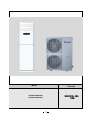
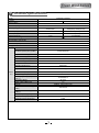
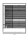
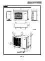
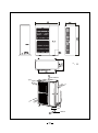
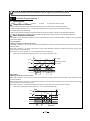
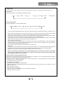
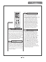
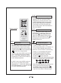
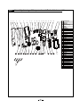
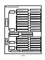
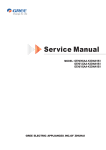
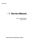
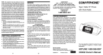
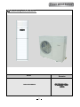
Fresh Wind Series
1 Summary and features
Model
GVA24AG-K3NNA5A
Remarks
Model
GVA36AH-M3NNA5A
GVA48AH-M3NNA5A
Remarks
Fresh Wind Series
2 Technical specifications
Model
GVA24AG-K3NNA5A
Function
COOLING
HEATING
Rated Voltage
1PH 220-240V~
Rated Frequency
Total Capacity (W/Btu/h)
50Hz
7050/ 24040
7800(9900)/ 26598(33759)
Power Input (W)
2430
2350(4450)
Rated Input (W)
3250
3250(5350)
Rated Current (A)
14.13
Air Flow Volume (m 3/h) (H/M/L)**
Dehumidifying Volume (l/h)
EER / C.O.P (W/W)
Energy Class
Model of Indoor Unit
Fan Motor Speed (r/min) (H/M/L)
Output of Fan Motor (w)
Input of Heater (w)
Fan Motor Capacitor (uF)
Fan Motor RLA(A)
Fan Type-Piece
Diameter-Length (mm)
Evaporator
Indoor Pipe Diameter (mm)
unit Row-Fin Gap(mm)
Coil length (l) x height (H) x coil
width (L)
Swing Motor Model
Output of Swing Motor (W)
Fuse (A)
Sound Pressure Level dB (A)
(H/M/L)
Sound Power Level dB (A)
(H/M/L)***
Dimension (W/H/D) ( mm)
14.13(23.26)
1100
3
2.90/3.32
/
GVA24AG-K3NNA5A/I
510/450/425/390
50
2100
4.5
0.23
Centrifugal fan - 1
φ350X130
Aluminum fin-copper tube
φ7
2-1.3
724X390X25.4
MP35AA
1.8
PCB 5A Transformer 0.2A
48/45/42/40
58/55/52/50
500X1757X300
Dimension of Package(W/H/D)(mm)
1940X630 X 435
Net Weight /Gross Weight (kg)
40/60
Model of Outdoor Unit
Compressor Manufacturer/trademark
Compressor Model
Compressor Type
L.R.A. (A)
Compressor RLA(A)
Compressor Power Input(W)
Overload Protector
Throttling Method
Starting Method
Working Temp Range (℃)
Condenser
Pipe Diameter (mm)
Rows-Fin Gap(mm)
Coil length(l) x height(H) x coil width(L)
Fan Motor Speed (rpm) (H/M/L)
Output of Fan Motor (W)
Outdoor Fan Motor RLA(A)
Fan Motor Capacitor (uF)
unit
Air Flow Volume of Outdoor Unit
Fan Type-Piece
Fan Diameter (mm)
Defrosting Method
Climate Type
Isolation
Moisture Protection
Permissible Excessive Operating
Pressure for the Discharge Side(MPa)
Permissible Excessive Operating
Pressure for the Suction Side(MPa)
Sound Pressure Level dB (A) (H/M/L)
Sound Power Level dB (A) (H/M/L)
Dimension (W/H/D) (mm)
Dimension of Package (L/W/H)(mm)
Net Weight /Gross Weight (kg)
Refrigerant Charge (kg)
Length (m)
Gas additional charge(g/m)
Connecti Outer
Liquid Pipe (mm)
on Pipe Diameter
Gas Pipe (mm)
Max
Height (m)
Distance
Length (m)
GVA24AG-K3NNA5A/O
PANASONIC
5VS270EAA21
ROTARY
45.3/49.7
10.0/10.4
2265/2360
INTERAL
Capillary
Capacitor
-7 ℃≤T≤43 ℃
Aluminum fin-copper tube
φ9.52
2-1.4
665×813×44
850
70
0.3
3.5
3000 m3/h
Axial fan -1
Ф450
Auto defrost
T1
I
IP24
4.5
1.6
56
66
1018x840x412
1100x450x905
69/74
R410A/2.1
4
0
Ф9.52(3/8")
Ф16(5/8")
10
20
The above dataa are subject to change without norice. Please refer to the nameplate of the unit.
Fresh Wind Series
Model
GVA36AH-M3NNA5A
Function
COOLING
Rated Voltage
GVA48AH-M3NNA5A
COOLING
HEATING
3N~ 380-415V~
3N~ 380-415V~
50HZ
50Hz
Rated Frequency
Total Capacity (W/Btu/h)
HEATING
11000
12700(15200)
12400W
13600(16100)W
Power Input (W)
3920
4220(6720)
4940
4840(7340)
Rated Input (W)
5800
5600(8100)
6400
5800(8300)
7.1
7.6(12.2)
11.6
10.5(15)
Rated Current (A)
3
Air Flow Volume (m /h) (H/M/L)**
Dehumidifying Volume (l/h)
EER / C.O.P (W/W)
1700
1800
4.5
6
2.81/3.01
2.51/2.81
/
/
GVA36AH-M3NNA5A/I
GVA48AH-M3NNA5A /I
Energy Class
Model of Indoor Unit
Fan Motor Speed (r/min) (H/M/L)
Output of Fan Motor (w)
Input of Heater (w)
450/410/370/330
450/410/370/330
500/460/420/380
500/460/420/380
120
120
2500
3500
6
6
1.36
1.36
Centrifugal fan - 1
Centrifugal fan - 1
φ379X180.5
φ379X180.5
Aluminum fin-copper tube
Aluminum fin-copper tube
¢7
¢7
2-1.4
3-1.5
876.3X470X38.1
876.3X470X57.15
MP35AA
MP35AA
4
PCB 5A Transformer 0.2A
4
PCB 5A Transformer 0.2A
51/49/47/45
52/50/48/46
51/49/47/45
52/50/48/46
518X1870X395
518X1870X395
Dimension of Package(W/H/D)(mm)
735X530X2080
735X530X2080
Net Weight /Gross Weight (kg)
60/86
63/89
Fan Motor Capacitor (uF)
Fan Motor RLA(A)
Fan Type-Piece
Diameter-Length (mm)
Evaporator
Indoor Pipe Diameter (mm)
unit Row-Fin Gap(mm)
Coil length (l) x height (H) x coil
width (L)
Swing Motor Model
Output of Swing Motor (W)
Fuse (A)
Sound Pressure Level dB (A)
(H/M/L)
Sound Power Level dB (A)
(H/M/L)***
Dimension (W/H/D) ( mm)
Model of Outdoor Unit
Compressor Manufacturer/trademark
Compressor Model
Compressor Type
L.R.A. (A)
Compressor RLA(A)
Compressor Power Input(W)
Overload Protector
Throttling Method
Starting Method
Working Temp Range (℃)
Condenser
Pipe Diameter (mm)
Rows-Fin Gap(mm)
Coil length(l) x height(H) x coil width(L)
Fan Motor Speed (rpm) (H/M/L)
Output of Fan Motor (W)
Outdoor Fan Motor RLA(A)
Fan Motor Capacitor (uF)
unit
Air Flow Volume of Outdoor Unit
Fan Type-Piece
Fan Diameter (mm)
Defrosting Method
Climate Type
Isolation
Moisture Protection
Permissible Excessive Operating
Pressure for the Discharge Side(MPa)
Permissible Excessive Operating
Pressure for the Suction Side(MPa)
Sound Pressure Level dB (A) (H/M/L)
Sound Power Level dB (A) (H/M/L)
Dimension (W/H/D) (mm)
Dimension of Package (L/W/H)(mm)
Net Weight /Gross Weight (kg)
Refrigerant Charge (kg)
Length (m)
Gas additional charge(g/m)
Connecti Outer
Liquid Pipe (mm)
on Pipe Diameter
Gas Pipe (mm)
Max
Height (m)
Distance
Length (m)
GVA36AH-M3NNA5A/O
DAIKIN
JT125G-P8Y1
SCROLL
48.2
5.4
3000
INTERAL
Capillary
/
-7 ℃≤T≤43 ℃
Aluminum fin-copper tube
Ф7
2-1.5
730X1218X25.4
830
68
0.3
3.5
4000
Axial fan -2
Ф472
Auto defrost
T1
I
IP24
GVA48AH-M3NNA5A /O
SANYO
C-SBP160H38A
SCROLL
72
8.33
4600
INTERAL
Capillary
/
-7 ℃≤T≤43 ℃
Aluminum fin-copper tube
Ф9.52
2-1.6
730X1218X44
830
68
0.3
3.5
4000
Axial fan -2
Ф472
Auto defrost
T1
I
IP24
3.8
3.8
1.2
1.2
59
67
1032x1250x412
1110/1280/450
105/116
R410A/3.2
5
0
Ф12
Ф19
5
10
59
67
1032x1250x412
1110/1280/450
110/121
R410A/3.6
5
0
Ф12
Ф19
5
10
The above dataa are subject to change without norice. Please refer to the nameplate of the unit.
Fresh Wind Series
3 Part name
Air outlet
Display screen
Indoor unit
and button
Front panel
Air out
Remote controller box
Air intake grille
Air in
LED displayer
Remote control window
Speed
Function
AMB.
Mode
ON/OFF
Outdoor unit
Air in
Connecting Pipe
Drainage hose
Note:This is a example of 24K for outdoor unit.
Air out
4 Outline and installation dimension
Outline and installation dimensions of indoor unit
D
H
W
air in grille
pipe outlet
back view
distance with the ceiling
top view
distance with the wall
distance with the wall
distance with obstacles
Model
24K
36/48K
W(㎜)
500
518
H(㎜)
1757
1870
D(㎜)
300
395
Fresh Wind Series
Outline and installation dimensions of outdoor unit
412
378
840
1018
950
572
Unit:mm
Ov
er
30
Over 600mm
0m
m
O
O
300
ver
mm
Bolt
Nut
Wrench
ve
r
0
60
m
m
unit
Over 600mm
Over
300m
m
O
O
300
ver
600
ver
mm
mm
Bolt
Nut
Wrench
Fresh Wind Series
5 Electrical circuit diagram
GVA24AG-K3NNA5A
OUTDOOR UNIT
W2
W6 BK
6
N(1)
0
W10 BU
KM
W7
1
RELAY
M1
XT2
2
YV
C2
J1
HEATER
BU
BU
SWING-LR
O-HEAT1
I-HEAT1
BN
BK
YE
VT
OG
YEGN
PE
KM1
COMP
OVC
4V
OFAN
CN1
CN2
O-HEAT2
I-HEAT2
KM2
AP1
CN3
L
CN4
FAN
CN5
X4
CN8
C
X4
RT1
M2
E
C1
M1
BN
BU
TUBE
TEM.SENSOR
0
2
FAN
RT1 0
YEGN
PE
X1
FAN MOTOR
W8
CN1
M2
X101
CN390 CN391
TR-IN TR-OUT1 TR-OUT2
(BK)
W1
CN2
M3
AC-L N1
BN
PE
X2
AP2
SWING-UD
BN
RD BN
BU
1
DISPLAY
TC
W11
BU W3
BU
RD
BU
VT
OG
ST
EH
5
HIGH PRESSURE
SWITCH
W12
R
YE W4
X3
2
3
P
E
S
W13 YE 1
YEGN
FUT
BU
N(4)
YEGN
S1
BU
C COMP.
L
YEGN
BU
PE
BN
XT
BU
N(1)
BK
2
BN
3
BN
W14
(BK)
N
BN
3
XT2
RD
BU
BK
2
4
1
W5
W9
POWER
XT1
BU
BU
YEGN
RT2
0
ROOM
TUBE
TEM.SENSOR TEM.SENSOR
YEGN
INDOOR UNIT
GVA36AH-M3NNA5A GVA48AH-M3NNA5A
BN
L1
BK
L2
VT
L3
BN
BU
N
BN BK VT
YEGN
BU
C
T
S
R
A
BN
FU
5
3
1
2
6
4
BN BK VT
(V)
(U)
COMP.
MOTOR
E
FA
REVERSAL
DEFENSIBLE
PROTECTOR
OVER
CURRENT
PROTECTOR
T1
T2
COMP
~
T3
(W)
PE
YEGN
BN
C1
(BK)
BU BN BN OG
(BK)
(WH)
M4
~
M3
~
FAN
EH
YEGN
PE
(WH)
PE
PE
MOTOR
YEGN
3
4
5
1
2
2
3
4
PE
EH1
EH2
RD
EH3
BU
SWING-UD
2
X3
0
WH YE
WH BU
HP
P
LP
P
YV
4YV
HI. PRES.
PROTECTOR
DISCHARGE GAS
TEMP. SENSOR
LO. PRES.
PROTECTOR
X5
X4
0
RT1
0
ROOM
TEMP. SENSOR
RT2
CN2
M3
SWING-LR
CN1
M2
2BN
YEGN
PE
AC-L
N1
I-HEAT1
I-HEAT2
OVC
4V
OFAN
LPP
COMP
I-HEAT3
FAN
KM1
KM2
KM3
AP2
O-HEAT1
O-HEAT2
O-HEAT3
CN390
CN1
CN2
AP1
CN391
X101
CN4
L
CN3
CN5
CN448
CONNECTER(RD)
BN
WH RD
XT4
5YE
6VT
7OG
8WH
9BK
1
2
5
1
C2
BU BN BN OG
X2
3
4
X2
BU
A1
CONNECTER
2
1
A2
22
1
CONNECTOR
BU
KM
CONTACTOER
X1
YE
VT
OG
WH
BK
XT3
WH
21
RD
SAT2 BU
PE
2
BU
BU FUT2 BU
SAT1
4YEGN
1BU
1
BU
BU
N
YEGN
BU
BN BK VT
L3
YEGN
XT2
B
L2
BU
N
YEGN
N
HEARTER
RD FUT1 RD
BK
14BN
15BK
16VT
L1
VT
L3
BU
L3
BK
L2
VT
FA
BN
BK
VT
BU
BN
L1
BK
TERMINAL BOARD
XT
POWER
L2
TERMINAL BOARD
XT1
PE BN
A
YEGN
L1
1 10WH
2 11RD
3 12BU
4 13YE
PIPE
TEMP. SENSOR
RT3
BL
PE
INDOOR UNIT
BU
X3
X1
CONNECTER
CN8
WH
C
WH
X4
M1
PE
FAN MOTOR
YEGN
RT1
TRANSFORMER
RT2
0
ROOM TEMP.
SENSOR
0
PIPE TEMP.
SENSOR
OUTDOOR UNIT
on
6 PCB function manual and operation method
Controller Function Manual 1
一、 Running Mode
1. cooling;
2. dry;
3. fan;
4: heating;
5. AUTO;
6. others (Freon recovery mode).
二、Temperature Parameter
1. Indoor ambient temperature Tamb. (adopt 15K temperature sensor, external connect 15K partial resistance);
2. Outdoor ambient temperature Toutdoor amb. (adopt 15K temperature sensor, external connect 15K partial resistance);
3. Discharge temperature (Tdischarge)
4. Indoor evaporator tube temperature Tevaporator (adopt 20K temperature sensor, external connect 20K partial resistance);
5. Outdoor condenser tube temperature Tcondenser (adopt 20K temperature sensor, external connect 20K partial resistance).
三、Basic Functions of System
In all modes, once the compressor is started up, it will run within 6mins all the time; once the compressor is stopped, it can only be started
up after 3mins delayed.
(一) Cooling Mode
1. Working conditions and process of cooling
When Tamb.≥Tpreset+1℃, the unit will run in cooling mode. Meanwhile, compressor, outdoor fan will start running, and indoor will run at
setting fan speed;
When Tamb.≦Tpreset-1℃, the unit is at OFF status in cooling mode. Meanwhile, compressor, outdoor fan will all stop running, while
indoor fan will run at setting fan speed;
When Tpreset-1℃<Tamb.<Tpreset+1℃, the unit will keep previous running status.
¾
In this mode, the temperature setting range is 16℃~30℃ and the initial value is 25℃.
Tamb.
start cooling
Tpreset
original running status
Tpreset
mins
stop cooling
mins
mins
compressor
outdoor fan
indoor fan
setting fan speed
stop
(二) Dry Mode
run
1. Working conditions and process of dry
When Tamb.>Tpreset+2℃, the unit will run in cooling mode. Meanwhile, compressor and outdoor fan will start running, and indoor fan will
run at low fan speed;
When Tpreset-2≦Tamb.≦Tpreset+2℃, compressor and outdoor fan will run for 6mins and then stop for 4 mins, and they will run like that
circularly. Indoor fan will run at low fan speed;
When Tamb.<Tpreset-2℃, compressor and outdoor fan will stop running, while indoor fan will run at low fan speed.
¾
In this mode, the temperature setting range is 16℃~30℃ and the initial value is 25℃.
Tamb.
cooling
Tpreset
drying
Tpreset
mins
mins
mins
mins
stop running
compressor
outdoor fan
indoor fan
low fan speed
run
low fan speed
low fan speed
stop
Fresh Wind Series
(三) Heating Mode (this mode is not available for cooling only unit)
1. Working condition and process for heating
When Tamb.≦Tpreset-1℃, the unit will run in heating mode. Meanwhile, compressor and outdoor fan will start running. Indoor fan may
be start running after delayed for a period of time to prevent blowing out cold air. If the unit turns to heating mode for the first time or
switches to heating mode from other modes, the four-way valve will be energized after compressor was started up for the first time for20s.
When Tamb.≥Tpreset+1℃, compressor and outdoor fan will stop running. The four-way valve is energized all the same and indoor fan
will stop running after running at low fan speed for 10s;
When Tpreset-1℃<Tamb.<Tpreset+1℃, the unit will keep original running status;
¾
In this mode, the temperature setting range is 16℃~30℃ and the initial value is 25℃. When tuning off the unit in heating mode or
switching to other modes from heating mode, the four-way valve will be de-energized after 2mins delayed.
¾
When turning off the unit, if the complete unit is at running status in heating mode, the unit will stop running when reaching the
setting temperature and the unit will be turned off after lowing residual heat for 10s. If the unit is at the status of blowing residual
heat when the unit is stopped after reaching the temperature point, the unit will continue to blow residual heat and then it will be
turned off; if the unit is stopped after reaching the temperature and indoor fan is stopped, the unit will be turned off directly without
blowing residual heat.
stop heating
Tpreset
original running status
Tpreset
mins
compressor
setting fan speed
outdoor fan
indoor fan
start heating
mins
mins
6
6
low fan speed
anti cold air
low fan speed
anti cold air
reversing valve
run
stop
2. Defrosting condition and process
System will defrost intelligently and automatically. When it’s detected that the system is reached the defrosting condition, the system will
turn to defrosting status;
After defrosting is started up, H1 will be displayed. If there’s auxiliary heating, auxiliary heating will be stopped and then compressor,
indoor fan and outdoor fan will stop running after 1min delayed. 3mins later, the four-way valve will be closed. After four-way valve has
closed for 30s, compressor will be started up.
After defrosting is finished, compressor will stop running, while the four-way valve will be start up. 30s later, compressor and outdoor fan
will be restarted up and turn to the next periods. Indoor fan is running at anti cold air status.
Defrosting time can’t exceeds 12mins at the most.
3. Working condition for auxiliary heating
Auxiliary heating can be turned on/off by buttons.
If auxiliary heating is at ON status, when indoor fan is running, and indoor ambient temperature and air discharge temperature are low,
auxiliary heater will start running;
When indoor fan isn’t running, or indoor ambient temperature is high, or air discharge temperature is high, auxiliary heater will stop
running. Once the auxiliary heater is stopped, it can only be restarted up after 2mins delayed.
If auxiliary heating is set OFF, the auxiliary heating will be turned off directly.
(四)Fan Mode
Indoor fan is running at setting fan speed:
auto fan speed
low fan speed
medium fan speed
high fan speed
¾
The temperature setting range is 16℃~30℃ and the initial value is 25℃.
(五) Auto Mode
In this mode, the system will select the running mode (cooling, dry, heating, fan) automatically according to the change of ambient
temperature.
¾
Once the mode is started up, the unit will only switch to the running status under auto mode according to Tamb after it has run for
30s at least.
(六)Freon Recovery Mode
That’s the recovery operation method for refrigerant:
1. After the A/C is energized for the first time, set the A/C at FAN mode, low fan speed by remote controller and the indoor
temperature is set as 20℃; Meanwhile, indoor fan will start running.
2. Press the light button on remote controller for twice successively within 5s; meanwhile, indoor fan and compressor will start running
automatically.
3. After compressor has run for 3mins, close the cut-off valve completely.
4. When the protector for low-voltage switch has an action, compressor and outdoor unit will stop running automatically. Please close
the cut-off valve immediately.
5. After stopping blowing wind by remote controller, the refrigerant recovery operation is finished completely.
Notice: 1. After refrigerant is recovered, if the recovery operation should be operated again, please cut off the power at first and then put
through the power again.
2. Above methods are applicable for the movement or reinstallation of indoor unit or outdoor unit; during this process, the low
voltage switch can’t be short circuited.
四、Other Controls
1. Sleep Function
Sleep in cooling mode:
When initial temperature is set as 16~23℃, after sleep function is started up, the temperature will increase by 1℃ every 1hr. After the
temperature has increased by 3℃, the unit will keep this temperature. After the unit has run for 7hrs, the temperature will decrease 1℃
and then the unit will run at this temperature all the time.
When initial temperature is set as 24~27℃, after sleep function is started up, the temperature will increase by 1℃ every 1hr. After the
temperature has increased by 2℃, the unit will keep this temperature. After the unit has run for 7hrs, the temperature will decrease 1℃
and then the unit will run at this temperature all the time.
When initial temperature is set as 28~29℃, after sleep function is started up, the temperature will increase by 1℃ every 1hr. After the
temperature has increased by 1℃, the unit will keep this temperature. After the unit has run for 7hrs, the temperature will decrease 1℃
and then the unit will run at this temperature all the time.
When initial temperature is set as 30 ℃, the unit will run at this temperature. After the unit has run for 7hrs, the temperature will
decrease by 1℃ and then the unit will run at this temperature all the time.
Sleep in heating mode:
When initial temperature is set as 16℃, the unit will run at this temperature all the time;
When initial temperature is set as 17~20℃, after sleep function is started up, the temperature will decrease by 1℃ every 1hr. After the
temperature has decreased for 1℃, the unit will keep this temperature.
When initial temperature is set as 21~27℃, after sleep function is started up, the temperature will decrease by 1℃ every 1hr. After the
temperature has decreased for 2℃, the unit will keep this temperature.
When initial temperature is set as 28~30℃, after sleep function is started up, the temperature will decrease by 1℃ every 1hr. After the
temperature has decreased for 3℃, the unit will keep this temperature.
Sleep in dry mode:
When setting sleep function in dry mode, after the sleep function has run for 1hr, Tpreset will increase by 1℃ and it will increase by
another 1℃ after 2hrs. Tpreset will increase by 2℃ at all within 2hrs and then the unit will run at this temperature.
Sleep in fan mode and auto mode:
Sleep function is nor available in fan mode and auto mode.
2. Timer Function
Timer ON: Timer ON can be set at the OFF status of the unit. After timer ON is reached, controller will run according to the setting mode.
The time setting range is 0.5~25hrs and the interval is 0.5hr. If the time on display screen is less than 10hrs, the display interval is 0.5hr;
if the time is more than 10hrs, the display interval is 1hr.
Timer OFF: Timer OFF can be set at the ON status of the unit. After timer OFF is reached, the unit will be turned off. The time setting
range is 0.5~25hrs and the setting interval is 0.5hr. If the time on display screen is less than 10hrs, the display interval is 0.5hr; if the
time is more than 10hrs, the display interval is 1hr.
3. Swing Control
Swing motor can be turned on/off by pressing the swing button on remote controller. Swing is valid only when the indoor fan is running.
Right & left swing: swing blade has 7 kinds of status: ① angle 1, ② angle 2, ③ angle 3,
④angle 4, ⑤ angle 5, ⑥ swing, ⑦ stop. After the unit is turned on by the ON/OFF button on
control panel every time, the default status of swing is OFF and the position is ③ angle 3.
set this place as the starting point
After the unit is turned on by remote controller, the status of swing motor is basing on the
( 0°)
display status on remote controller.After the unit is energized every time, right & left swing
motor will be reset.
ķ ĸ Ĺ
ĺ Ļ
UP & down swing: when turning off the unit, the swing blade will stop at the starting point (zero
ķ
position). When turning on the unit, there are 7 kinds of status: ① angle 1 (max position), ② angle
2, ③angle 3, ④angle 4, ⑤angle 5 (min position), ⑥swing, ⑦stop. If turn on the unit by the
ĸ
ON/OFF button on control panel, the setting swing status is basing on the status before turning off
the unit; while if turn on the unit by remote controller, the setting swing status is basing on the
Ĺ
status on remote controller (if the receiving remote controller is 35, 25, 24, 14 or 13, it’s ⑥
swing). When turning on the unit each time (including turn on the unit by remote controller or
ĺ
control panel), if the setting swing status is not ⑦stop, then it will at the actual swing status; if the
Ļ
setting swing status is ⑦stop, after turning the unit, it will be defaulted at angle 3 in cooling, angle
4 in heating and angle 3 in dry. As for mode switchover, it will also switch like that until the setting
set this place as the starting point (0° )
swing status is not ⑦stop, then the above compulsory default status will be cancelled.
Fresh Wind Series
When turning on the unit each time, the swing blade must be open to angle 5 (mini position), and then compressor, fan etc. can run.
When switching on controller or turning off the unit each time, the swing blade must be at OFF status.
4. Buzzer
Upon energization or operation, the buzzer will give out pleasant sound (digital chord).
5. Auto Fan Speed Control of Indoor fan
In auto fan speed, indoor fan will select high, medium or low fan speed automatically according to the change of ambient temperature.
For the switchover between any two kinds of fan speed, the unit must be make sure that it has run at each fan speed for 3mins and 30s
at least.
6. AIR Function (it’s reserved for some models)
AIR function is invalid when the unit is turned off. Upon receiving the order for starting up AIR function from remote controller or control
panel, indoor fan will be turned on and the AIR function will be started up; once receiving the order for turning off AIR function n, AIR
function will be turned off. After the unit is turned off, AIR function will be cleared automatically.
7. BLOW function
Blow function can be turned on/off by the FUNCTION button on control panel or BLOW·E-HEATER button on remote controller.
If start up BLOW function in cooling or dry mode, after the unit is turned off, indoor unit will still run for a few minutes to dry the water
inside the unit, and then the indoor unit will be turned off automatically.
8. Turbo Function
In cooling and heating mode, turbo function can be turned on/off (there’s no turbo function in auto, dry and fan mode) by the turbo button
After pressing turbo button for once, remote controller will display the characters of “turbo” and fan speed won’t change, Meanwhile,
indoor fan will run at super-high fan speed and display panel will display the super-high fan speed; After repressing turbo button, th
turbo function will be quitted and the characters of “turbo” on remote controller will be disappeared. Meanwhile, indoor fan will turn back
to setting fan speed. Super-high fan speed will also be quitted after operating the fan speed button and the fan speed will also be
changed correspondingly. Display panel will display the setting fan speed.
Turbo function is default to be turned off when remote controller is energized.
When restarting up the unit or switching the mode, turbo function will be memorized.
When restarting up the unit by remote controller and controller or switch to cooling or heating mode, turbo function will be memorized.
While when switching to auto, dry or fan mode, the turbo function is unavailable.
9. Power-off Memory Function
When re-energizating the unit after power failure, the unit will run at the memory content. Memory content : mode, up&down swin
(7kinds of status), right and left swing (7 kinds of status), setting temperature, setting fan speed, light, timer, turbo, AIR, health and
environment mode.
If the unit is at ON status after power failure, compressor will be started up 3mins delayed after energization; if the unit is at OFF status,
compressor will be started up without 3mins delayed.
If the timer hasn’t been reached before power failure, the unit will time again according to the setting timer before power failure.
五、Protective Measures
1. Indoor antifreezing protection
When cooling in cooling mode or dry mode (that’s Tamb>Tpreset+2℃), if it’s detected that the evaporator tube temperature is too low
the system will turn to antifreezing protection status. Meanwhile, compressor and outdoor fan will stop running, while indoor fan and
swing motor will keep original status. When evaporator tube temperature resumes to normal range and compressor has stopped for
6mins, controller will run at the setting mode.
Buttons won’t be shielded during the antifreezing protection.
2. High-pressure protection of system
When the high-pressure protection is detected for 3s successively, all loads will be turned off. Meanwhile, all buttons and signal will be
shielded and E1 will be displayed. When it’s detected that the high-pressure protection of compressor has been released for 6s
successively, the shield for button and signal will be released and E1 will still be displayed. E1 can be cleared after pressing ON/OF
button to turn off the unit. The unit will resume running after repressing ON/OFF button.
3. Low-voltage protection of system
This function is unavailable for some modes. But if the controller is the general controller and the shielded wire of low-pressur
protection is loosened or not connected well, it will take it as low-pressure protection by mistake. The details are as below:
1. After compressor is started up for 2mins, it will begin to detect the signal of low pressure switch. If it’s detected that the low pressure
switch is broken for 1mins successively, the complete unit will stop running. 3mins later, if the low pressure switch is resumed, the unit
will resume running automatically. If low pressure switch protection occurs for 2 times successively, E3 will be displayed and the u
can’t resume running automatically to warn users that it’s leaking. After restarting up the unit and low pressure switch is resumed, the
unit will resume running.
2. When compressor is stopped, if it’s detected that the low pressure switch is broken for 30s successively, the complete unit will stop
running. Meanwhile, E3 will be displayed and the unit can’t resume running automatically. Only after restarting up the unit and the low
pressure switch is resumed, the unit can resume sunning.
3. When compressor hasn’t been start up after energization each time, if it’s detected that the low pressure switch is broken for 1s
successively, all loads won’t be turned on after turning on the unit, and E3 will be displayed on the display screen. E3 will still be
displayed after restarting up the unit. Only when the low pressure switch is resumed, E3 will be cleared and then all loads will run
normally.
4. In compulsory cooling or heating mode, it will begin to detect the signal of low pressure switch after compressor has started up for
2mins. When it’s detected that the low pressure switch is broken for 1s successively, the complete unit will stop running and E3 will be
displayed. During compulsory heating, if outdoor ambient temperature ≦0℃, the detection for low pressure switch will be shielded.
Correct disposal method: after cutting off the power, insert the shielded wire again to make sure that the shielded wire is connected
firmly and then restart up the unit.
4. High temperature protection for discharge pipe
After the compressor is started up, if it’s detected that the discharge temperature is too high for 30s successively, the unit will stop
running when indoor ambient temperature is reached to setting temperature. When compressor has stopped for 3mins and discharge
temperature resumes to normal range Tdischarge <90℃, the complete unit will resume running.
If above protection is occurred for twice successively, the complete unit can’t resume running and E4 will be displayed. When restarting
up the unit and Tdischarge <90℃, the unit will run at setting mode.
If turning on the unit to turn to heating mode or switching to heating mode from other modes, discharge protection will be shielded for
1min when compressor is started up for the first time.
5. Indoor high temperature resistance protection
In heating mode, when it’s detected that the evaporator tube temperature is too high, outdoor fan will stop running; when evaporator
tube temperature resumes to normal range, outdoor fan will be started up.
6. Overcurrent protection
After compressor is started up, if it’s detected that the current is exceeds I0 (I0=25A) for 3s successively, the unit will stop running when
Indoor ambient temperature is reached to setting temperature. After compressor has stopped for 3mins, the unit will resume original
running status. If protection times exceeds 6 times, indicator will blink and display E5 and the unit can’t resume original running status.
The unit can only resume running after restarting up the unit.
7. Malfunction of temperature sensor
Under ON status, it will detect the malfunction of indoor tube temperature (exclude defrosting period and the period when defrosting is
finished for 5mins) and outdoor discharge temperature sensor (in heating mode, it starts detecting the malfunction after compressor has
started up for 1min; the malfunction won’t be detected when compressor is stopped). It’s the malfunction when they are short circuit
or broken circuit for 30s successively. When there’s malfunction of temperature sensor, the complete unit will stop running. Meanwhile
the indicator will blink and display the corresponding error code. Malfunction of temperature sensor won’t shield the button and remote
controller.
8. Malfunction and protection code
E1: high-pressure protection of system;
E3: low-pressure protection of system;
E4: high temperature protection for discharge pipe;
E5: overcurrent protection;
F1: malfunction of indoor ambient temperature sensor;
F2: malfunction of indoor tube temperature sensor;
F3: malfunction of outdoor ambient temperature sensor
F4: malfunction of outdoor tube temperature sensor
F5: malfunction of discharge temperature sensor
When multiple malfunctions are occurred simultaneously, each malfunction error will be displayed for 3s and they be will displayed in
cycle.
六、Button
When remote controlling by remote controller:
1. If the display mode for remote controller is the heating mode and A/C is the cooling only type, A/c won’t receive other signal except
the signal for turning off the unit.
2. If pressing the invalid button on remote controller, the buzzer will still give out a sound but the function won’t be carried out.
There are those buttons on the panel: ON/FF button, mode button, ambient setting button, ▲ button, ▼button, function button, fan
speed button.
Display screen:
Speed
Function
AMB.
Mode
ON/OFF
Fresh Wind Series
1. ON/OFF button
Controller is turned on/off by pressing this button. After each pressing of this button, the on/off status will be switched for once.
2. Mode button
After pressing this button, it will be selected and displayed as below:
Auto
cooling
dry
fan
heating
(heat pump type)
3. Ambient setting button
After pressing AMB. button, it will be selected as below:
SAVE mode
①
②
③
④
⑤
room mode
office mode
restaurant mode
common mode
In each mode, after pressing AMB. mode on control panel, the ambient mode can be selected and cycled as : SAVE mode---room
mode---office mode---restaurant mode---common mode; when the unit is turned on for the first time, ambient mode is default as
common mode; when restarting up the unit, ambient mode will keep the setting status before turning off the unit.
When using the remote controller, the unit can only turn to SAVE mode or common mode after receiving the order from remote
controller, and the unit will run according to the order transmitted by remote controller all the time.
In SAVE mode, room mode, office mode or restaurant mode, sleep will be cancelled automatically and sleep can’t be adjusted;
Sleep is only valid in cooling, dry and heating mode under the common mode.
Room, restaurant and office modes
Cooling and heating mode: setting temperature, fan speed and swing will run at the default status. If users have adjusted the
parameters, they will run according to adjusting status. 30mins later, it will turn back to auto adjusting status; when restating the
unit, swing will keep the status before turning off the unit.
Fan, dry and auto mode: running status is the same as that in common mode.
SAVE mode
In cooling mode: setting temperature and fan speed can be adjusted automatically; if users have adjusted the setting temperature
and setting fan speed, it will run according to the adjusting status. 30mins later, it will turn back to auto adjusting status.
Heating, fan, dry and auto mode: the running status is the same as that in common mode.
Notice: room, restaurant and office mode can only be adjusted by buttons on control panel. If controller is receiving the
order from remote controller when it’s running in room, restaurant or office mode, those modes will be quitted and it will
run according to the mode on remote controller.
4. Selection button for setting temperature (▲and▼)
(1) During the status when don’t set the function, after pressing ▲ button or ▼button for once, the setting temperature will increase or
decrease for 1℃ and the temperature setting range is 16℃~30℃.
(2) During the status when setting the function, the function can be selected circularly. (the circulatory direction for ▲and▼ is opposite)
① up & down (swing)
: swing, stop swinging.
② right & left (swing): swing, stop swinging.
③ blow: start up blow, turn off blow.
④ E-HEATER: start up E-HEATER, turn off E-HEATER.
⑤ TIMER: set timer and it can be adjusted among 0~24hrs. If the time is less than 10hrs, the interval is 0.5hr; if the time is more than
10hrs, the interval is 1hr.
⑥ AIR: start up AIR, turn off AIR.
⑦ Sleep: start up sleep, turn off sleep.
⑧ Health: start up the electrostatic dedusting, turn off the electrostatic dedusting.
⑨ Turbo: start up turbo, turn off turbo.
⑩Setting: default to display the setting temperature at ON status, default to display the setting temperature at off status
⑾ Room temperature: default to display room temperature at on status, default to display to room temperature at off status.
(3) After pressing ▲ button and ▼button simultaneously, all buttons on the display panel will be shielded. When pressing any buttons,
the buzzer will give out a sound and dual 8 will display “LC”. The display will resume normal after the dual 8 blinks 3 times to warn users
that the buttons are locked. When repressing those two buttons simultaneously, shield will be released and the display will resume
normal status.
(4) After the unit is energized for the first time, if there isn’t any input:
① If pressing ▲ buttons within 20s successively, the unit will turn to compulsory heating immediately and up & down swing blade will
open to angle I (minimum position). Meanwhile, all loads will be started up and indoor fan and outdoor fan will run at high fan speed.
When there’s no malfunction of temperature sensor, all characters will be displayed. When there’s malfunction of temperature sensor,
dual 8 will display error codes circularly and the buzzer will give out sound. When the unit is stopped 5 mins later or the unit is stopped
after receiving the signal for turning off the unit within 5mins, the unit will turn to normal standby status.
② If pressing ▼button within 20s successively, the unit will turn to compulsory cooling immediately and up & down swing blade will
open to angle I (minimum position). Meanwhile, all loads will be turned on except the four-way valve and the indoor fan and outdoor fan
will run at high fan speed. When there’s no malfunction of temperature sensor, all characters will be displayed. When there’s malfunction
of temperature sensor, dual 8 will display error codes circularly and the buzzer will give out sound. When the unit is stopped 5 mins later
or the unit is stopped after receiving the signal for turning off the unit within 5mins, the unit will turn to normal standby status.
After above tests are all displayed for 2s, it will begin to detect the malfunction of indoor ambient, indoor tube temperature, outdoor
ambient, outdoor ambient, outdoor tube temperature and discharge temperature sensor. When it’s detected that there are multiple
malfunctions, each error code will be displayed for 3s and they will be displayed circularly.
Item ① and ② are only used for testing. During this period, high pressure, overcurrent and discharge protection won’t be detected.
5. Function button
In the ON state of the unit, after each pressing of the function button, you can switch among up&down swing, right&left swing, blow,
E-HEATER, timer, AIR, sleep, health (this is unavailable for L-shape floor standing A/C), turbo, setting and room temperature setting in
sequence. When a certain character is blinking, it means that you can set this function and you can press “▲”button or “▼”button to
set it. The setting will be confirmed after the setting has been set for 5 mins and there’s no change for the operation.
In blow running status, the unit will be turned off after pressing the function button. If repressing the function button, you can set the
timer or health function.
After a function is selected by function button, if the unit hasn’t been turned off and it hasn’t received the signal from remote controller
within 2 mins, the unit will circulate starting from the original setting function after repressing the function button. 2mins later or the unit is
turned off or the unit has received the signal from remote controller, the unit will circulate from the first icon after repressing function
button.
6. Fan Speed Button
After pressing speed button, it will be selected and displayed as:
auto
low medium
high
七、 Display Method
1.Middle Number Part
(1) When there’s malfunction protection (E1, E3, E4, E5, F2, F5), the unit only displays the error code and others won’t be displayed.
When there’s multiple malfunctions, those malfunctions will be displayed circularly.
(2)In the normal running status, when setting temperature or timer is set, the unit will display the corresponding setting for 5s. After that,
the unit will display the setting temperature and it will default to display H1 during the time of defrosting. When setting the setting
temperature, timer and temperature display, they will be displayed in sequence as below: setting temperature, timer, temperature
display and defrosting H1 and each status will be displayed for 5s. If one status (setting temperature, timer, temperature display,
defrosting H1) isn’t exist, that status will be omitted and the display will stop at the defaulted or setting temperature display. After the unit
is energized, it defaults to display the ambient temperature.
The corresponding character and icon will be displayed simultaneously.
2. Fan Speed
When setting auto, low, medium and low fan speed, the corresponding character for the selected fan speed will be bright, and others
won’t be bright.
When setting auto, cooling, dry, fan and heating mode, the corresponding character for the selected mode will be bright and others
won’t be bright. The character and icon for the selected mode will be bright simultaneously. In auto mode, the auto and actual running
mode will be displayed at the same time.
3. Ambient Mode
Ambient mode is including 5 kinds of mode: SAVE mode, room mode, office mode, restaurant mode and common mode. The selected
ambient mode will be bright, others won’t be bright.
①
②
Up&down swing: when setting up&down swing, the icon and character will blink; when selecting the up&down swing, the icon and
the character of (up&down) will be displayed. When there’s no up&down swing or the swing the stopped, the icon and the
character of “up&down” won’t be displayed.
Right&left swing: when setting right&left swing, the icon and character will blink; when selecting the right&left swing, the icon and
the character of (right&left swing) will be displayed. When there’s no right&left swing swing or the swing the stopped, the icon and
the character of “right&left swing” won’t be displayed.
Fresh Wind Series
Blow: when setting blow function, the icon and character will blink; when this function is selected, the icon and character will be
displayed. If the blow function hasn’t been selected, the icon and character won’t be displayed. During the time of blow, only the
icon and character are displayed, others won’t be displayed.
④ E-HEATER: when setting E-HEATER function, the icon and character will blink; when this function is selected, the icon and
character will be displayed. If the E-HEATER function hasn’t been selected, the icon and character won’t be displayed.
⑤ Timer: when setting timer function, the icon and character will blink; when this function is selected, the icon and character will be
displayed. If the timer function hasn’t been selected, the icon and character won’t be displayed.
⑥ AIR: when setting AIR function, the icon and character will blink; when this function is selected, the icon and character will be
displayed. If the AIR function hasn’t been selected, the icon and character won’t be displayed.
⑦ Sleep: when setting AIR function, the icon and character will blink; when this function is selected, the icon and character will be
displayed. If the sleep function hasn’t been selected, the icon and character won’t be displayed.
⑧ Health: when setting AIR function, the icon and character will blink; when this function is selected, the icon and character will be
displayed. If the health function hasn’t been selected, the icon and character won’t be displayed.
⑨ Turbo: when setting turbo function, the character will blink; when this function is selected, the character will be displayed. If the
turbo function hasn’t been selected, the character won’t be displayed.
⑩ Setting: when setting function, the character of setting will blink; when this function is selected, the character will be displayed and
the dual 8 will display the setting temperature. If the setting function hasn’t been selected, the character and setting temperature
won’t be displayed.
⑪ Room temperature: when setting function, the character of room temperature will blink; when this function is selected, the
character will be displayed and the dual 8 will display the indoor room temperature. If the room temperature function hasn’t been
selected, the character and indoor room temperature won’t be displayed.
5. Indicator Control
When the unit is at standby status after energizing, the power LED will be bright. After the unit is turned on, the running LED will be
bright. When any one of the circumstances as below are occurred, the running LED will blink: defrosting, overcurrent protection, high
pressure protection of compressor, low pressure protection of compressor, high temperature protection of discharge pipe,malfunction of
indoor tube temperature sensor, malfunction of discharge temperature sensor.
6. Light Control
LED display can be turned off by the light button on remote controller. When using remote controller to cancel “light”, the complete LED
displayer screen will go out, except the running LED. When turning off the light, if there’s signal from button or remote controller, LED will
go out after displaying for 5s.
③
Operation of remote controller
1. Names and functions of remote controller
Note: Be sure that there are no obstructions between receiver and remote controller; Don't drop
or throw the remote controller; Don't let any liquid get into the remote controller and put the remote
controller directly under the sunlight or any place where is very hot.
(ˇ/ˉ)
Signal transmitter
●
FAN
(ˇ/ˉ) button
When pressing +button , the setting temp. will be
increased by 1ć ,When press -button,the
setting temp. will be decreased by 1 ć
The temp. will be changed quickly by pressing
AUTO
OPER
AIR HEALTH BLOW
HUMIDITY
the button continuously and the setting temp. range
is ̚ćDŽ
FILTER
TURBO
TEMP.
HOUR
ON/OFF
FAN
ON/OFF
Remote controller
MODE
●
FAN speed button
After pressing this button , fan speed will change
as below:
Auto
Low speed
Middle speed
FAN
ON/OFF
BLOW
TEMP
TIMER
TURBO
SLEEP
LIGHT
High speed
Note:Under the Dry mode, the fan speed can't
be adjustable and low fan speed is imperative,
but when operating this button, the remote
controller will send this signal.
up & down swing button
ON/OFF button
General swing mode is defaulted for remote controller.
In this mode, after pressing this button, you
● After pressing this button, the unit will turned on/off,
could turn on or turn off the up & down
an it can clear the timer or sleeping function of
swing function.
last time.
●
When the unit is turned off and pressing "+" and
up & down swing buttons simutanously, it could
MODE
Mode button
be switched between the general swing
● After pressing this button, the running mode will
mode and stationary swing mode. Meanwhile,
change as below.
blinks 2 seconds.
●
●
AUTO
In Stationary swing mode, after pressing this button,
the angle for up & down swing is show as below:
COOL
DRY
●
FAN
HEAT (Note:this is unavailable
for coolling only unit)
When up & down swing louver is working, after
turning off the unit, the swing louver will be
stopped immediately at current position.
.
shows that the up & down swing louver swings up
and down as shown in the above figure.
Fresh Wind Series
FAN
AUTO
OPER
AIR HEALTH BLOW
HUMIDITY
TIMER
●
FILTER
TURBO
HOUR
ON/OFF
ON/OFF
Remote control
HEALTH SAVE
●
●
MODE
FAN
BLOW
TEMP
TIMER
TURBO
SLEEP
LIGHT
HEALTH SAVE button
HEALTH function:there isn't health function
for this unit. If press this key, the main unit
will click, but it also runs under original status.
Save energy function: this unit hasn't this
function, press this button, the main unit will
click, "SE" will be displayed on the LCD of
remote controller, fan speed automatically
rotates, when repress this button, the fan speed
will run at previous setting fan speed.
TURBO
●
Turbo button
Set turbo on or off(the characters of turbo
will appear or disappear ) by pressing this
button under cooling or heating mode.Once
energized, the unit will be defaulted to be
turbo off. This function can not be set under
auto, dehumidify or fan mode, and characters
of turbo won't appear.
At the on status of the unit , press this
button to set timer off. At the off status of
the unit , press this button to set timer
ON. Press this key once, character of Hour on(off)
will appear and flicker. In which case, press
+/- button to adjust time (press+/- button
continuously to change timing value quickly).
The setting time range is from 0.5 to 24 hrs;
press this key once again to fix the time,
then remote controller will send out the signal
immediately and hour on/off will stop flickering.
If the time of that no press timer button
under flickering status is above 5s,the timer
setting will quit. If the timer has been set,
press this button once again to quit it.
TEMP
●
Timer button
Temp. display button
After powered on, presetting
temperature is defaulted,(According to
customer requirements to display,if there
are no requirements,the presetting temperature displaying is defaulted, there is
no signal display on the remote controller).
Press this button, (display
), display
the presetting temperature; (display
),
display indoor ambient temperature,
(display
), display ambient temperature,
If current display status is indoor ambient temp.
when it received other remote control signal,
then it will display presetting temp. 5s later,
it will return to display ambient temp..
Other models are without this function. But
after pressing this button, the main unit will click
and keep the original status.
BLOW
Blow button
●
FAN
AUTO
OPER
AIR HEALTH BLOW
HUMIDITY
FILTER
TURBO
HOUR
ON/OFF
Remote controller
ON/OFF
MODE
LIGHT
●
FAN
BLOW
TEMP
TIMER
TURBO
SLEEP
LIGHT
SLEEP
After pressing this button, the unit will enter
into SLEEP state. when repressing it, SLEEP
will be quitted.The sleep function will be
canceled with the stop of the unit.There is
no SLEEP function under AUTO and FAN mode.
●
●
is the icon for sleep function.
●
●
At COOL mode: after SLEEP mode runs after
1hour, the setting temp. will be increased
by 1ć , 2 hour later, setting temp. will be
increased by 2ć and then the unit will run
at this setting temperature.
In HEAT mode: after SLEEP mode runs
after 1hour, the setting temp will be
decreased by 1ć, 2 hours later setting temp.
will be decreased by 2ć ,then the unit will
run at this setting temperature.
Light button
Press this button to select LIGHT on or off
on the displayer. When the LIGHT on is
set,the icon
will be displayed and the
light LED on the displayer will be bright.
When the LIGHT off is set, the icon
will
be displayed and the light LED on the
displayer will go out.
Left&right swing button
Sleep button
●
Set Blow ON (the characters of Blow will
appear)or OFF (the characters of Blow
disappears) by pressing this button under
cooling or dehumidify mode. Once energized,
the unit will be defaulted to be Blow OFF.
This function can not be set under auto,
fan or heating mode, and the characters of
Blow won't appear.
General swing mode is defaulted for
remote controller. In this mode,
after pressing this button, you could turn on
or turn off the Left&right swing function.
When the unit is turned off, synchronously
pressing "+" and Left&right swing button,
it could be switched between the general
swing mode and stationary swing mode.
At this time,
●
●
blinks 2 seconds.
In Stationary swing mode, after pressing this button,
the angle for Left & right swing is showed as below:
When left & right swing louver is working, after
turning off the unit, the swing louver will
immediately stop at current position.
shows that left &right swing louver swings
right and left as shown in the above figure.
Fresh Wind Series
2. Guide for operation- General operation
1.Press ON/OFF button to start the unit after powering the main unit on.
(Note: Power the unit on every time, the big -guide louver and small-guide
MODE
ON/OFF
louver will be closed firstly.)
2.Press MODE button to select your desired running mode.
3.Press +/ - button to set the desired temperature (It is unnecessary to
set the temperature at AUTO mode)
FAN
BLOW
TEMP
TIMER
TURBO
SLEEP
LIGHT
4. Press FAN button to set fan speed, the AUTO FAN, LOW, MID or
HIGH could be selected.
5. Press
button and
button to set swing mode.
3. Guide for operation- Optional operation
MODE
ON/OFF
1.Press SLEEP button to set the sleep mode.
2.Press TIMER button and then press +/- button to set the scheduled timer
FAN
ONor timer OFF.
3. Press LIGHT button to control displayer light on or off.
BLOW
TEMP
TIMER
TURBO
SLEEP
LIGHT
4. Press BLOW button to set Blow function on or off.
5. Press TURBO button to set this function on or off.
4. Changing batteries and notices
Slightly press the place with
1. ,
and then push the back cover of
remote controller along the arrowhead direction. (As show in figure)
2 Take out the old batteries. (As show in figure)
3. Insert two new AAA1.5V dry batteries, and pay attention to the polarity.
(As show in figure)
4 Attach the back cover of remote controller. (As show in figure)
ƾ NOTE:
ƽ When changing the batteries, do not use the old or different batteries,
otherwise, it can cause the malfunction of remote controller.
ƽ If the
remote controller won't be used for a long time, please
take them out and don't let the leakage liquid damage the
remote controller.
ƽ The operation should be in its receiving range.
ƽ It should be put at the places where is 1m away from the TV set or stereo sound sets.
ƽ If the remote controller can't be operated normally, please take the batteries out. Sketch map for
30s later, reinsert the batteries. If the unit can't still run normally, please
change the batteries.
changing batteries
Assembly drawing and parts' list
8
Assembly drawing of Components and Parts of Indoor unit 1
1
2
3
4
35
36
37 38
5
34
6
33
39
7
32 31 30
40
9 10
8
29
11
28 27 26 25 24
41
12
13 14
23 22
42
21
15
16
20 19
17
18
42
41
40
39
38
37
36
35
34
33
32
31
30
29
28
27
26
25
24
23
22
21
20
19
18
17
16
15
14
13
12
11
10
9
8
7
6
5
4
3
2
1
Screw Cover
Rear Grill
Electric Heater Tube
Connecting Cable
Connecting Cable
Connecting Cable
Power Cord
Rear Cover
Baffle Plate
Water Tray Sub-Assy
Chassis
Fan Motor
Centifugal Fan
Propeller Housing Sub-assy
Diversion Circle
Electric Box Assy
Transformer
Terminal Board
Capacitor CBB61
Relay
Main Board
Cover Plate assy of Electric Box
Filter sub-assy(upper)
Filter sub-assy(lower)
Air Intake panel Assy
Air Outlet Panel Assy
Latch
Air Guard Sub-Assy
Propeller housing press plate sub-assy
Display Board
Air Ducing Linkage
Swing Lever
Stepping Motor
Stepping Motor
Crank
Temperature Sensor
Evaporator Assy
Breakwater
Top Cover Sub-Assy
Right Side Plate Sub-Assy
Left Side Plate Sub-Assy
Rear Plate Sub-Assy
Fresh Wind Series
Description
Left Side Plate Sub-Assy
Right Side Plate Sub-Assy
Rear Plate Sub-Assy
Rear Cover
Baffle Plate
Propeller Housing Sub-assy
Propeller housing press plate sub-assy
Centrifugal fan
Diversion Circle
Fan Motor
Evaporator Assy
Rear Grill
Temperature Sensor
Breakwater
Water Tray Sub-Assy
Drainage Pipe Sub-assy
Air Guard Sub-Assy
Electric Box Assy
Main Board
Relay
Relay
Capacitor CBB61
Transformer
Terminal Board
Cover Plate assy of Electric Box
Chassis
Air Outlet Panel assy
Swing lever
Crank
Step Motor
Guide blade lever
Step Motor
Latch
Display Board
Air Intake panel Assy
Filter sub-assy(upper)
Filter sub-assy(lower)
Connecting Cable
Connecting Cable
Connecting Cable
Connecting Cable
Top Cover Sub-Assy
Screw Cover
The above datas are subject to change without norice.
Part Code
GVA24AG-K3NNA5A/I
0130412803
0130412903
01304134
2224422001
2611408801
1210420101
01364216
10314001
10374003
15014217
01004284
01474042
3900019003
26114118
20184022
05235434
01364183
0140451008
30134133
44020331
44020345
33010012
43110287
42010258
01404389
22224021
20004691
10584218
10564201
1521421102
10584088
1521400801
70811002
30563194
20004524
11124104
11124105
400205404
4003213431
4003213447
400205382
22244106
24252450
Qty
1
1
1
3
3
1
1
1
1
1
1
1
1
1
1
1
1
1
1
2
8
1
1
1
1
1
1
1
1
1
1
1
1
1
1
1
1
1
1
1
1
1
2
Assembly drawing of Components and Parts of Indoor unit 2
1
2
3
4
38
39
5
37
6
36
35 34
7
8
33
32
9
11
31
30
12
13 14
15
29 28 27 26
16
17
25
18
24
19
23
20
22
21 39 Connecting Cable
38
37
36
35
34
33
32
31
30
29
28
27
26
25
24
23
22
21
20
19
18
17
16
15
14
13
12
11
10
9
8
7
6
5
4
3
2
1
Rear Cover
Baffle Plate
Water Tray Sub-Assy
Chassis
Fan Motor
Centifugal Fan
Propeller Housing Sub-assy
Diversion Circle
Protective covering
Electric Box Assy
Transformer
Terminal Board
Capacitor CBB61
Main Board
Electric Box Cover Sub-Assy
Filter sub-assy
Air Intake panel Assy
Air Outlet Panel Assy
Latch
Air Guard Assy
Propeller housing press plate sub-assy
Display Board
Guide blade lever
Swing lever
Step Motor
Step Motor
Electric Heater Tube
Rear Grill
Crank
Ambient Temperature Sensor
Capillary Sub-Assy
Evaporator Assy
Breakwater Sub-Assy
Top Cover Sub-Assy
Right Side Plate Sub-Assy
Left Side Plate Sub-Assy
Rear Plate Assy
Fresh Wind Series
Description
Rear Plate Assy
Fan Motor
Propeller Housing Sub-assy
Left Side Plate Sub-Assy
Right Side Plate Sub-Assy
Rear Cover
Baffle Plate
Propeller housing press plate sub-assy
Centrifugal fan
Diversion Circle
Protective covering
Chassis
Evaporator Assy
Capillary sub-assy (heating)
Electric heater
Rear Grill
Breakwater Sub-Assy
Water Tray Sub-Assy
Drainage Pipe Sub-assy
Ambient Temperature Sensor
Top Cover Sub-Assy
Air Guard Assy
Electric Box Assy
Main Board
Relay
Relay
Terminal Board
Transformer
Capacitor CBB61
Electric Box Cover Sub-Assy
Air Outlet Panel assy
Swing lever
Step Motor
Guide blade lever
Crank
Step Motor
Latch
Display Board
Air Intake panel Assy
Filter Sub-Assy
Screw Cover
Connecting Cable
Connecting Cable
Connecting Cable
Connecting Cable
Part Code
GVA36AH-M3NNA5A/I
01304290
1501442405
12104058
0130430401
0130430301
2224422001
2611408801
01384063
10314401
10374435
01474027
22224020
01004314
03004029
32004079
1474034
01364154D
12314811
05235434
39000190
22244109
01364174
0140484201
30134135
44020331
44020345
42010258
43110287
33010037
01404388
2000453403
10584218
1521421102
10584089
10564201
1521400801
70810302
30563195
20004536
11124100
24254018
40020539
400205391
40032117
40030328
The above datas are subject to change without norice.
GVA48AH-M3NNA5A/I
01304290
1501442404
12104058
0130430401
0130430301
2224422001
2611408801
01384063
10314401
10374435
01474027
22224020
0100408101
0300401101
32004079
1474034
01364154D
12314811
05235434
39000190
22244109
01364174
0140484201
30134135
44020331
44020345
42010258
43110287
33010037
01404388
2000453403
10584218
1521421102
10584089
10564201
1521400801
70810302
30563195
20004536
11124100
24254018
400205391
400205392
40032117
40030328
Qty
1
1
1
1
1
3
3
1
1
1
1
1
1
1
1
1
1
1
1
1
1
1
1
1
3
8
1
1
1
1
1
1
1
1
1
1
1
1
1
1
2
1
1
1
1
Assembly drawing of Components and Parts of outdoor unit 1
7
6
8
9
5
10
4
3
11
12
2
13
14
1
15
31
16
17
30 29 28
24
27
26
25
23
22
21
20
19
18
31 Capillary Sub-Assy
30 4-way Valve Accessary
29 4-way Valve Assy
28 Discharge Tube
27 Drainage Plug
26 Drainage Connecter
25 Tube sensor
24 Pressure Protect Switch
23 Handle
22 Front Side Plate
21 Chassis Sub-assy
20 Clapboard Sub-Assy
19 Compressor and fittings
18 Valve Support Sub-Assy
17 Gas Valve Sub-Assy
16 Left Handle
15 Rear Side Plate Sub-Assy
14 Terminal Board
13 Electric Box Assy
12 Capacitor CBB61
11 AC Contactor
10 Capacitor CBB65
9 Electric Box Cover Plate
8 Rear Grill
7 Top Cover
6 Condenser Assy
5 Motor Support
4 Fan Motor
3 Axial Flow Fan
2 Cabinet
1 Front Grill
Fresh Wind Series
Description
Chassis Sub-assy
Compressor and fittings
Part Code
GVA24AG-K3NNA5A/O
01203628P
00103080
Qty
1
1
Condenser Assy
01105481
1
Capillary Sub-Assy
03005286
1
Cut-off Valve
07130209
1
Clapboard Sub-Assy
012352534
1
Clapboard Sub-Assy
01235254
1
Motor Support
01705253
1
Fan Motor
15015210
1
Cabinet
01435254
1
Axial Flow Fan
10335253
1
Magnet Coil
430004002
1
Discharge Tube
03615552
1
Valve Support Sub-Assy
01715001
1
Tube sensor
390001214
1
Electric Box Assy
01405281
1
Electric Box Cover Plate
01413047
1
Terminal Board
42010258
1
Terminal Board
42011103
1
AC Contactor
44010222
1
Capacitor CBB65
33000039
1
Capacitor CBB61
33010010
1
Top Cover
01255262
1
Front Grill
22265251
1
Rear Grill
01475252
1
Front Side Plate
01305247
1
Insulated board (cover of electric box)
20113003
1
Rear Side Plate Sub-Assy
01303709
1
26235253
26235401
07103030
03025065
460200061
06123401
06813401
2
1
1
1
1
1
3
Handle
left handle
Gas Valve Sub-Assy
4-way Valve Assy
Pressure Protect Switch
Drainage Connecter
Drainage Plug
The above datas are subject to change without norice.
Assembly drawing of Components and Parts of outdoor unit 2
8
9
10
11
12
13
15
16
7
14
6
17
5
4
18
3
19
2
20
21
22
1
23
24
25
26
34
33
32
31
30
29
28
27
34
33
32
31
30
29
28
27
26
25
24
23
22
21
20
19
18
17
16
15
14
13
12
11
10
9
8
7
6
5
4
3
2
1
Drainage Plug
Front Side Plate
Clapboard Sub-Assy
Chassis Sub-assy
Compressor and fittings
Electric heater(compressor)
Terminal Board
Drainage Connecter
Valve Support Sub-Assy
Handle
Rear Side Plate Sub-Assy
Inhalation Tube Assy
Air-out Temp. Sensor
Gas-liquid Separator Sub-Assy
4-way Valve Assy
Capillary Sub-Assy
Outdoor Tube Sensor
Electric Box Assy
Transformer
Terminal Board
Terminal Board
Phase Reverse Protector
Over Current Protector
Capacitor CBB61
AC Contactor
Rear Grill
Top Cover
Condenser Assy
Ambient Temperature Sensor
Motor Support Sub-Assy
Fan Motor
Axial-flow Fan
Cabinet
Front grill
Fresh Wind Series
Description
Part Code
Qty
GVA36AH-M3NNA5A/O
012054332
GVA48AH-M3NNA5A/O
012054335
Valve Support Sub-Assy
01715001
01715001
1
Compressor and fittings
00102701
00105021
1
Overload Protector
00180132
/
0
Chassis Sub-assy
1
Compressor Gasket
76815209
/
0
Terminal Board
42010157
42010157
2
electrical heater
76515407
76515404
1
Condenser Assy
01105484
01105556
1
Capillary Sub-Assy
03005477
03005479
1
Clapboard Sub-Assy
01235440
01235440
1
Outdoor Tube Sensor
390001941
39000194
1
Ambient Temperature Sensor
39000199
39000199
1
Air-out Temp. Sensor
39000163
39000163
1
Gas-liquid Separator Sub-Assy
07225018
07225018
1
Motor Support Sub-Assy
01705433
01705433
1
Fan Motor
15015421
15015421
2
Cabinet
01435436
01435436
1
Axial Flow Fan
10338731
10338731
2
4-way Valve Assy
03025126
03025235
1
Cut-off Valve
07130212
07130212
1
Pressure Protect Switch
460200061
460200061
1
Magnet Coil
430004002
430004002
1
03633836
03635163
1
Inhalation Tube Sub-Assy
Pressure Protect Switch
46020007
46020007
1
Electric Box Assy
0140547039
01255262
1
Capacitor CBB61
33010010
22414102
2
AC Contactor
44010226
01305431
1
Over Current Protector
Transformer
Relay
Terminal Board
Terminal Board
Phase Reverse Protector
Relay
Top Cover
Front grill
Front Side Plate
Rear Grill
Rear Side Plate Sub-Assy
Handle
Drainage Connecter
Drainage Plug
46020112
43110242
44020332
42010258
42011103
46020052
44020369
01255262
22414102
01305431
01475005
01303712
26235253
06123401
06813401
01475432
01303712
26235253
0140547039
33010010
44010226
46020112
43110242
44020332
42010258
42011103
46020052
44020369
06123401
06813401
1
1
1
2
2
1
1
1
2
1
1
1
3
1
3
The above datas are subject to change without norice.
9 Trouble-Shooting
When setting the circuit breaker at "ON", it will
be tripped off immediately
Breaker is tripped over
or the fuse is burnt out
When the A/C is turn to "ON", the circuit breaker
will be tripped off in a few minutes
Check the power supply circuit
The power plug hasn't been inserted well
or poor connection
Check and insert the plug well
Poor
(heating)
or
cooling
Check wether the wires connection are
wrong according to electric circuit, and
connect the wires correctly
Transmitting malfunction of
remote controller
Check the remote controller
Fuse of controller is burnt out
Replace the fure of controller
Check whether the wire connection between
strong and electric plate and weak electric plate
of controller is firm
Indoor unit and
outdoor unit can't
be started up
Check the breaker and measure
the resistance for short cuircuit
No power supply
Wrong wire connection between
indoor unit and outdoor unit
A/C can't
be started
up
Ground and measure the insulation
resistance, confirm whether the A/C
is leaking or short circuit
Check whether the outlet line of transformer is
connected firmly, whether there's voltage output
Connect the wires firmly
Connect the wires firmly and check
the output voltage
The setting temperature is improper
Adjust the setting temperature
Check whether the cooling(heating)
load is sufficient
Check the preset cooling(heating) load
Malfunction of
refrigerant flowage
Malfunction of the four-way valve
Replace the four-way valve
Refrigerant is insufficient
Complement the refrigerant
Malfunction of compressor
Replace the compressor
Flowage volume of valve is insufficient
Air circulation is
insufficient
Increase the flowage volume of valve
Filter is blocked
Clean the filter
Fan speed is set too low
Set the fan speed to high or medium
Installtion position of outdoor unit is
improper
Outdoor unit should be installed at the place with good ventilation and
you can install the flashing plate and sun-proof plate
Fresh Wind Series
Poor
(heating)
or
cooling
The fan can't run
when setting fan
In cooling or heating
mode, the outdoor unit
and the compressor
don't run.
In cooling or heating
mode, the compressor
is running, while
outdoor fan don't run
Filter of indoor unit is blocked
Clean the filter periodically
Heat exchanger of outdoot unit is blocked
Get rid of the dust accumulated on heat exchanger
There's leakage between high voltage
and low voltage in compressor
Replace the compressor
Part of the capillary is blocked
Refrigerant is leaking
Find out the leakage and complement
the refrigerant
One-way valve of outdoor unit is blocked
Replace the one-way valve
Oudoor fan's motor is burnt out
Repair or replace the fan's motor
Wrong wire connection
Connect the wire correctly according to the electric
circuit diagram
Fan's capacitor is burnt out
Replace the fan's capacitor with same model and
specification
Coil of relay is broken
Replace the relay
Poor connection for relay
Replace the relay
The setting temperature is improper
Adjust the setting temperature
Outdoor fan's motor is broken
Replace the fan's motor
Wrong wire connection
Connect the wire correctly according to the electric
circuit diagram
Outdoor fan's capacitor is damaged
Replace the fan's capacitor
Malfunction of the compressor
In cooling or heating
mode, the outdoor fan
is running, while the
compressor doesn't run
Replace capillary
Capacitor of compressir is broken
Voltage is low or high
Wrong wire connection
Replace the compressor
Replace the capacitor
Suggest to eqquip with voltage regulator
Connect the wire correctly according to the electric
circuit diagram
Drain pipe is blocked or broken
Replace the drain pipe
The junction of the refrigerant pipe hasn't wrapped
well
Wrap it again and wrap it tightly
Leakage
Abnormal sound and
vibration
The fan of indoor unit will contact other parts
Adjust the fan's position
There are foreign substances in the indoor unit
Take out the foreign substances
Abnormal vibration of compressor
Adjust the compressor support pad and tighten
the loosened bolt
The pipes for outdoor unit are in collision
with each other
Separate the collision pipes
Metal plates in the unit are in collision with
each other.
Tighten the screws
Stick the damping plaster among metal plates
The blade of outdoor unit is in collision
with the cabinet
Adjust the blade's position
There is abnormal sound in the compressor
Replace the compressor
There is abnormal sound in the four-way valve
when heating
Electromagnetic valve is short-circuit
and replace it.
Notice: malfunction related to heating is not available for cooling only unit.
Malfunction 1: A/C has no action after energizing, and buzzer won't give out a beep.
please check the power or replace the controller
Malfunction 2: Display board displays "F1"
Indoor ambient temperature sensor hasn't been connected to the controller firmly, please insert it again or replace it.
Malfunction 3: Display board displays "F2"
Indoor tube temperature sensor hasn't been connected to the controller firmly, please insert it again or replace it.
Malfunction 4: Display board displays "F3"
Outdoor ambient temperature sensor hasn't been connected to the controller firmly, please insert it again or replace it.
Malfunction 5: Display board displays "F4"
Outdoor tube temperature sensor hasn't been connected to the controller firmly, please insert it again or replace it.
Malfunction 6: Display board displays "F5"
Outdoor discharge temperature sensor hasn't been connected to the controller firmly, please insert it again or replace it.