1
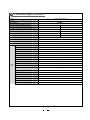
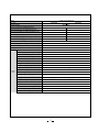
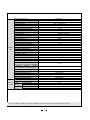
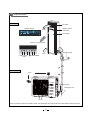
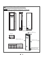
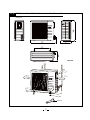
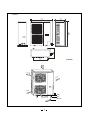
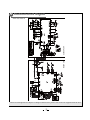
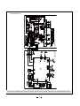
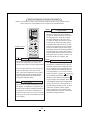
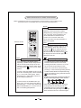
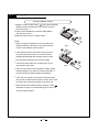
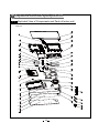
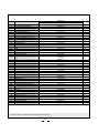
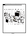
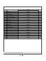
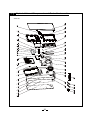
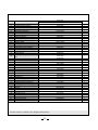
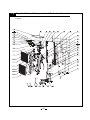
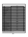
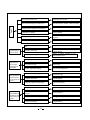
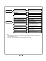
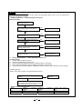
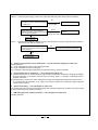
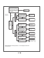
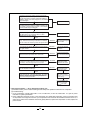
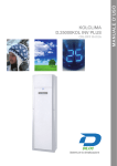
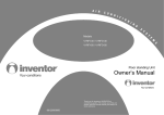
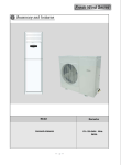
2 Technical specifications Model V1RFI-30/V1RFO-30 Function COOLING HEATING 220-240V~ Rated Voltage Frequency(Hz) (High/Standard/Low) Total Capacity (W) (High/Standard/Low) Total Capacity (Btu/h) (High/ Standard/Low) Power Input (W) (High/ Standard/Low ) Rated Input (W) (High/ Standard) Rated Current (A) (High/ Standard) Air Flow Volum e (m 3/h) (S/H/M/L) Dehum idifying Volum e (l/h) EER / C.O.P (W/W) Energy Clas s Model of Indoor Unit Fan Motor Speed (r/m in) (S/H/M/L) Output of Fan Motor (w) Input Power of Heater (w) 78/60/12 100/62/12 8300/7030//2500 9400/7800/1600 28500/24000/8500 32000/26500/5500 3600/2191/800 3600/2151/550 3600/2191 3600/2180 16.5/10 16.5/10 1000/820/750/650 2 3.21/3.61 A/A V1RFI-30 540/460/420/370 90 / Fan Motor Capacitor (uF) 4uF Fan Motor RLA(A) 0.68 Fan Type-Piece Diam eter-Length (m m ) Evaporator Pipe Diam eter (m m ) Indoor unit Row-Fin Gap(m m ) Coil length (l) x height (H) x coil width (L) Swing Motor Model Output of Swing Motor (W) Fus e (A) Cros s flow fan – 1 ¶ 108 X 954 Alum inum fin-copper tube 7 3-1.4 762 h 42 h 410 Stepping m otor SM060Aǃ Stepping m otor MP35CB 60 ǃ 35 PCB 3.15A Trans form er 0.2A Sound Pres s ure Level dB (A) (H/M/L) 48/45/43/40 Sound Power Level dB (A) (H/M/L) 58/55/53/50 Dim ens ion (W/H/D) ( m m ) 540/1790/320 Dim ens ion of Package (L/W/H)( m m ) 682/2005/475 Model of Outdoor Unit Compressor Manufacturer/trademark Compressor Model Compressor Type L.R.A. (A) Compressor RLA(A) Compressor Power Input(W) Overload Protector Throttling Method Starting Method Working Temp Range (ć) Condenser Pipe Diameter (mm) Rows-Fin Gap(mm) Coil length (l) x height (H) x coil width Fan Motor Speed (rpm) (H/M/L) Output of Fan Motor (W) Fan Motor RLA(A) Outdoor Fan Motor Capacitor (uF) unit Air Flow Volume of Outdoor Unit Fan Type-Piece Fan Diameter (mm) Defrosting Method Climate Type Isolation Moisture Protection Permissible Excessive Operating Pressure for the Discharge Side(MPa) Permissible Excessive Operating Pressure for the Suction Side(MPa) Sound Pressure Level dB (A) (H/M/L) Sound Power Level dB (A) (H/M/L) Dimension (W/H/D) ( mm) Dimension of Package (L/W/H)( mm) Net Weight /Gross Weight (kg) Refrigerant and Charge (kg) Length (m) Gas additional charge(g/m) Connecti Outer Liquid Pipe (mm) on Pipe Diameter Gas Pipe (mm) Max Height (m) Distance Length (m) V1RFO-30 SANYO C-7RZ233H1A rotary compressor 34 8.2 1760 INTIIL-3979 Electronic Expansion Valve Transducer starting -7ćİTİ48ć Aluminum fin-copper tube Φ7 2-1.4 942h748h42 780 90 0.85 7 Axial fan –1 Φ552 Auto defrost T1 I IP24 3.8 1.2 56 66 980x790x440 1065x840x485 65/71 R410A/1.950 5 30g/m Φ6 Φ16 10 20 The above data is subject to change without notice. Please refer to the nameplate of the unit. Model V1RFI-50/V1RFO-50 COOLING Function HEATING 380-415V~ Rated Voltage Frequency(Hz) (High/Standard/Low) 75/53/30 70/58/30 Total Capacity (W) (High/Standard/Low) 13500/12300/6200 15200/14000/6400 Total Capacity (Btu/h) (High/ Standard/Low) 46000/42000/21000 52000/48000/22000 5500/3950/1800 5500/3900/1700 5500/3950 5500/3900 Power Input (W) (High/ Standard/Low ) Rated Input (W) (High/ Standard) Rated Current (A) (High/ Standard) Air Flow Volum e (m 3/h) (S/H/M/L) Dehum idifying Volum e (l/h) EER / C.O.P (W/W) Energy Clas s Model of Indoor Unit Fan Motor Speed (r/m in) (S/H/M/L) Output of Fan Motor (w) Input Power of Heater (w) 8.9/6.8 8.9/7.3 1750/1680/1600/1500 4 3.21/3.61 A/A V1RFI-50 550/490/440/390 150 / Fan Motor Capacitor (uF) 6uF Fan Motor RLA(A) 0.68 Fan Type-Piece Diam eter-Length (m m ) Evaporator Pipe Diam eter (m m ) Indoor unit Row-Fin Gap(m m ) Coil length (l) x height (H) x coil width (L) Swing Motor Model Output of Swing Motor (W) Fus e (A) Cros s flow fan – 1 ¶ 369X180 Alum inum fin-copper tube 7 3-1.4 520X25.4X876 Stepping m otor SM060Aǃ Stepping m otor MP35CB 60 ǃ 35 PCB 3.15A Trans form er 0.2A Sound Pres s ure Level dB (A) (H/M/L) 50/47/44/42 Sound Power Level dB (A) (H/M/L) 53/50/47/45 Dim ens ion (W/H/D) ( m m ) 580/1865/400 Dim ens ion of Package (L/W/H)( m m ) 735/2105/545 Model of Outdoor Unit Compressor Manufacturer/trademark Compressor Model Compressor Type L.R.A. (A) Compressor RLA(A) Compressor Power Input(W) Overload Protector Throttling Method Starting Method Working Temp Range (ć) Condenser Pipe Diameter (mm) Rows-Fin Gap(mm) Coil length (l) x height (H) x coil width Fan Motor Speed (rpm) (H/M/L) Output of Fan Motor (W) Fan Motor RLA(A) Outdoor Fan Motor Capacitor (uF) unit Air Flow Volume of Outdoor Unit Fan Type-Piece Fan Diameter (mm) Defrosting Method Climate Type Isolation Moisture Protection Permissible Excessive Operating Pressure for the Discharge Side(MPa) Permissible Excessive Operating Pressure for the Suction Side(MPa) Sound Pressure Level dB (A) (H/M/L) Sound Power Level dB (A) (H/M/L) Dimension (W/H/D) ( mm) Dimension of Package (L/W/H)( mm) Net Weight /Gross Weight (kg) Refrigerant and Charge (kg) Length (m) Gas additional charge(g/m) Connecti Outer Liquid Pipe (mm) on Pipe Diameter Gas Pipe (mm) Max Height (m) Distance Length (m) V1RFO-50 SANYO C-9RVN273H0R rotary compressor 37.5 7.69 4380 / Capillary Transducer starting -7ćİTİ48ć Aluminum fin-copper tube Φ9.52 2-1.4 750X44X1218 840 68 0.309 6 uF / Axial fan –2 φ472X165 Auto defrost T1 I IP24 3.8 1.2 58 61 950/1250/412 1110/1280/450 112/123 R410A/4.0Kg 5 30g/m Φ12 Φ19 10 20 The above data is subject to change without notice. Please refer to the nameplate of the unit. 3 Part name Indoor unit Air outlet Display Screen Air out 亢䗳 ࡳ㛑 ᓣ ᓔ݇ Display screen and button Front panel Remote control window Air in FAN FUNTION Wrapping Tape MODE ON/OFF Outdoor unit Air in Connecting Pipe Drainage hose Air out Note: This photo is about the models of 24K, the appearance of model of 48K are a little different from this picture. 4 Outline and installation dimension Outline and installation dimensions of indoor unit D H W Air in grill Outlet pipe opening Rear view Distance to ceiling Top view Distance to wall Distance to wall Unit:mm Dimension Applicable models To barrier Note:The distance from tubing side to the wall shall not be less than 30cm Outline and installation dimensions of outdoor unit V1RF0-30 Unit:mm Bolt Nut Wrench V1RF0-50 Unit:mm Bolt Nut Wrench 5 Electrical circuit diagram INDOOR UNIT OUTDOOR UNIT V1RFI-30/V1RF0-30 These circuit diagrams are subject to change without notice, please refer to the one supplied with the unit. INDOOR UNIT OUTDOOR UNIT V1RFI-50/V1RF0-50 These circuit diagrams are subject to change without notice, please refer to the one supplied with the unit. 1 Names and Functions of Remote Control Buttons Names and functions of remote control buttons Note: Be sure that there are no obstructions between receiver and remote control; Don't drop or throw the remote control; Don't let any liquid in the remote control and put the remote control directly under the sunlight or any place where is very hot. (ˇ/ˉ) Signal transmitter ● FAN (ˇ/ˉ) button Pressing +button , the setting temp will be increased by 1ć.Pressing -button,the setting temp. will be decreased by 1 ć The temp. will be changed quickly by pressing AUTO OPER AIR HEALTH BLOW HUMIDITY FILTER TURBO TEMP. the button continuously .Setting temp. range is 16~30 HOUR ON/OFF FAN ON/OFF FAN speed button MODE Remote controller ● Press this button once,then fan speed will change as below: Auto FAN Low speed BLOW TEMP TIMER TURBO SLEEP LIGHT Middle speed High speed Note:In Dry mode, the fan speed is unadjustable and the low fan speed is imperative,but when operating this button, the wireless remote control will send this signal. ON/OFF ● ON/OFF button Swing up and down button Press this button to start or stop the unit.It will clear timer or sleeping function of last time. MODE ● Simpleness swing mode is defaulted for wireless remote control.In this mode, pressing this button, can turn on or turn off the Up and down swing function. ● When unit is turned off, synchronously pressing "+" and Up and down swing buttons can make it switch between the simpleness swing mode and stationary swing mode. At this time the mark blinks 2 seconds. ● In Stationary swing mode, pressing this button,the angle for Up and down swing will show as below: ● Mode button Press this button, the running mode will change as below: AUTO COOL DRY ● FAN HEAT (Note:not for coolling When up and down swing louver is working, turning off the unit, the siwng louver will immediately stop at current position. shows and up and down swing louver swings back and forth as shown in the above figure. only unit) 12 Names and functions of remote control buttons NOTE: This Remote control is universal and it could be used for many models of units. Some buttons are not available to this unit will not be described below. FAN TIMER AUTO OPER AIR HEALTH BLOW HUMIDITY ● FILTER TURBO HOUR ON/OFF ON/OFF MODE FAN Remote control HEALTH SAVE ● ● BLOW TEMP TIMER TURBO SLEEP LIGHT HEALTH SAVE button HEALTH function:there is no this function for this unit. If pressing it, the main unit will click, but it also runs under original status. Save energy function: this unit has not this function.If pressing it, the mian unit will click, "SE" will be displayed on the LCD of wireless remote control, fan speed will autoacts. If repressing it, the fan speed will run at previous setting fan speed. TURBO ● Turbo button Set turbo on or off(the characters of turbo will appear or disappear ) by pressing this button under cooling or heating mode.Once energized, the unit will be defaulted to be turbo off. This function can not be set under auto, dry or fan mode, and characters of turbo won't appear. 13 On the status of the unit on, press this button to set timer off. On the status of the unit off, press this button to set timer off. Pressing it once, words Hour on(off) will appear and flicker. In this case, press +/- button to adjust time (press+/- button continuously to change timing value quickly. The setting time range is from 0.5 to 24 hr.; press it once again to fix the time,and then the remote controller will send out the signal immediately and hour on/off will stop flickering. If the time that do not press timer button under flickering status is above 5s,the timer setting will quit. If the timer has been set, press this button once again to quit. TEMP ● Timer button Temp. display button After powered on, displaying presetting temperature is defaulted.(Cccording to customer requirements to display;if there are no requirements,the presetting temperature displaying is defaulted.There is no signal display on the remote control). Press this button, (display ), displaying the presetting temperature; (display ), displaying indoor ambient temperature, will not change current display status. If current display status is indoor ambient temp. receive other remote control sginals, the unit will display presetting temp.. 5s later it will return to ambient temp. display. Other models haven't this function. But pressing this button, the main unit will click and keep the original status. Names and functions of remote control buttons NOTE: This Remote control is universal and it could be used for many models of units. Some buttons are not available to this unit will not be described below. BLOW Blow button ● FAN AUTO OPER AIR HEALTH BLOW HUMIDITY FILTER TURBO HOUR ON/OFF Remote control ON/OFF MODE LIGHT ● FAN BLOW TEMP TIMER TURBO SLEEP LIGHT SLEEP ● ● Light button Press this button to select LIGHT on or off in the displayer. When the LIGHT on is set,the icon will be displayed and the indicator light in the displayer will be on. When the LIGHT off is set, the icon will be displayed and the indicator light in the displayer will be off. Left and right swing button Sleep button ● Set Blow on (the characters of Blow will appear)or off (the characters of Blow disappears) by pressing this button under cool or dry mode. Once energized,the unit will be defaulted to be Blow off.This function can not be set under auto, fan or heat mode, and the characters of Blow won't appear. Press this button into SLEEP state.If repressing it, SLEEP will quit. Sleep function will be canceled with the stop of the unit. There is not SLEEP function under AUTO and FAN mode. is the icon for sleep function. In COOL mode: the SLEEP mode runs after 1hour and the setting temp. will be increased by 1ć. 2 hour later, setting temp. will be increased by 2ć and thenthe unit will run at this setting temperature. In HEAT mode: the SLEEP mode runs after 1hour, and the setting temp will be decreased by 1ć . 2 hours later setting temp. will be decreased by 2ć ,and then the unit will run at setting temperature. 14 ● ● Simpleness swing mode is defaulted for wireless remote control.In this mode, pressing this button could turn on or turn off the Left and right swing function When unit is turned off, synchronously pressing "+" and Left and right swing buttons, to make it switch between the simpleness swing mode and stationary swing mode.At this time, blinks 2 seconds. ● In Stationary swing mode, pressing this button,the angle for Left and right swing is shown as below: ● When left and right swing louver is working, turning off the unit, the siwing louver will immediately stop at current position. shows and left and right swing louver swings back and forth as shown in the above figure. Operation of Remote Controller *XLGHIRURSHUDWLRQJHQHUDORSHUDWLRQ Guide for operation-general operation 1.Press ON/OFF button to start the unit after powering the main unit on.(Note: Power the unit on every time, MODE ON/OFF the big -guide louver and small-guide louver will be closed firstly.) 2.Press MODE button to select desired running mode. FAN 3.Press +/ - button to set the desired temperature (It is unnecessary to set the temperature at AUTO mode) 4. Press FAN button to set fan speed, the AUTO FAN, LOW, MID or HIGH could be selected. 5. Press button and BLOW TEMP TIMER TURBO SLEEP LIGHT button to set swing mode. Guide for operation-optional operation 1.Press SLEEP button, set the sleep mode. MODE ON/OFF 2.Press TIMER button, then press +/- button, to set the cheduled timer on or timer off. FAN 3. Press light button to control displayer light on or off. 4. Press Blow button to set Blow function on or off. 5. Press turbo button to set this function on or off. BLOW TEMP TIMER TURBO SLEEP LIGHT Introduction for special function ƾ About blow function This function indicates that moisture on evaporator of indoor unit will be blowed after the unit is stopped to avoid mould. 1. Having set blow function on: After turning off the unit by pressing ON/OFF button indoor fan will continue running for about 10 min. at low speed. In this period, press blow button to stop indoor fan directly. 2. Having set blow function off: After turning off the unit by pressing ON/OFF button, the complete unit will be off directly. 15 ƾ About AUTO RUN When AUTO RUN mode is selected, the setting temperature will not be displayed on the LCD, the unit will be in accordance with the room temp. automatically to select the suitable running method and to make ambient comfortable. ƾ About turbo function If start this function, the unit will run at super-high fan speed to cool or heat quickly so that the ambient temp. approachs the preset temp. as soon as possible. ƾ About lock Press +and - buttons simultaneously to lock or unlock the keyboard. If the remote controller will be displayed on it, in which case, press any button, the mark will is locked, the icon flicker for three times. If the keyboard is unlocked, the mark will disappear. ƾ About switch between Fahrenheit and Centigrade Under status of unit off, press MODE and - buttons simultaneously to switch ćand ̧. ƾ About new function of defrosting It indicates: after starting this function by remote controller and the unit has been under defrost status, If turn off the unit by remote controller, the unit will not stop defrosting until it is finished; if change setting mode by remote controller, the function ,which is set last time, won't be carried out until defrosting finished. Operation of this function on or off: If remote controller is under off status, press mode button and blow button simultaneously in order to enter or cancel this new function. If the unit is under defrost mode, dual eight position on remote controller will display H1.If switch to heat mode, the position will display H1, which flickers for 5s, in which case, press +/- button, H1 will disappear and setting temp. be displayed. After remote controller is powered on the new defrost function will be defaulted to be closed. 16 3 Changing Batteries and Notices Changing batteries notices 1.Slightly to press the place with along the arrowhead direction to push the back cover of remote controller. (As show in Fig 1. ) 2.Take out the old batteries, insert two AAA alkaline cells. (As show in Fig 2.) 3.Attach the back cover of remote control. NOTE: ● When changing the batteries, do not use the old or different batteries, otherwise, it can cause the malf- Fig.1 unction of the wireless remote control. ● If the wireless remote control will not be used for a long time, please take them out, and don't let the leakage liquid damage the wireless remote control. ● The operation should be in its receiving range. ● It should be placed where is 1m away from the TV Fig.2 set or stereo sound sets. ● If the remote control cannot operate normally, please take the batteries out, and then reinsert it 30s later; if it is also abnormal ,please replace the batteries. ● If the main unit needs to be remote controlled, please aim remote controller at the receiver of main unit in order to improve the receiving sensitivity of the main unit. ● When the remote controller sends out signal, a mark will flicker for about 1s. The bell will ring if the main unit receives effective signal. 17 7 Explosive view and spare parts list Exploded View of Components and Parts of Indoor unit V1RFI-30 18 No Description 1 2 3 4 5 6 7 8 9 10 11 12 13 14 15 16 17 Rear Plate Sub-Assy Left Side Plate Sub-Assy Right Side Plate Sub-Assy Top Cover Sub-Assy Breakwater Sub-Assy Water Tray Sub-Assy Evaporator Assy Ambient Temperature Sensor Stepping Motor Stepping Motor Stepping Motor Electric Box Cover Sub-Assy Terminal Board Relay Fuse Display Board Display Sub-Assy Propeller housing press plate subassy Air Guard Assy Upper Front Panel Assy Electrostatic duster Front door plate sub-assy Front panel sub-assy Female Clip Filter (upper) Receiver Board Main Board Capacitor CBB61 Transformer Electric Box Assy Diversion Circle Propeller Housing Sub-assy Centrifugal fan Fan Motor Chassis Baffle Plate Rear Cover Humidity sensor Sensor Sub-Assy Connecting Cable Connecting Cable Drainage hose 18 19 20 21 22 23 24 25 26 27 28 29 30 31 32 33 34 35 36 37 38 39 40 41 42 Part Code V1RFI-30 01304126 01304130 01304131 22244089 01364108D 12414072 01004473 390001375 1521240302 15214002 1521240201 01404454 420111041 44020331 46010013 30568016 20104063 The above data are subject to be changed without notice. 19 Qty 1 1 1 1 1 1 1 1 1 1 1 1 1 2 1 1 1 01384050 1 01364113 2000419603 1101420302 26114127 20004199 45017002 11124223 30042027 30038011 33010013 43110292 01404837 10374003 12104054 10314001 1501421803 22224052P 26114088 22244220 30116072 20104005 400205402 400204056 05230013 1 1 1 1 1 1 1 1 1 1 1 1 1 1 1 1 1 3 3 1 1 1 1 1 Exploded View of Components and Parts of outdoor unit V1RF0-30 20 No 1 2 3 4 5 6 7 8 9 10 11 12 13 14 15 16 17 18 19 20 21 22 23 24 25 26 27 28 29 30 31 32 Part Code V1RFO-30 22415003 01435004P 01305045P 43005008 01205137P 46020006 03025166 00105204 01305044P 01715012P 07133157 26235001 33010009 42010255 0260306613 4300040033 30138171 06813401 06123401 3900028014 01475013 01255007 01105328 01413426 1501506204 10335005 01235034 01705025 01305043P 26235401 43130183 33000065 Description Front Grill Cabinet Front Side Plate Electronic Expansion Valve Chassis Sub-assy Pressure Protect Switch 4-way Valve Assy Compressor and fittings Right Side Plate Valve Support Sub-Assy Cut-off Valve Big Handle Capacitor CBB61 Terminal Board Electric Box Assy Magnet Coil Main Board Drainage Plug Drainage Connecter Temperature Sensor Rear Grill Top Cover Sub-Assy Condenser Assy Electric box (fireproofing) Fan Motor Axial Flow Fan Clapboard Sub-Assy Motor Support Sub-Assy Left Side Plate left handle reactor Capacitor CBB65 The above data are subject to be changed without notice. 21 Qty 1 1 1 1 1 1 1 1 1 1 1 1 1 1 1 1 1 2 1 1 1 1 1 1 1 1 1 1 1 2 1 2 Exploded View of Components and Parts of Indoor unit V1RFI-50 22 No Description 1 2 3 4 5 6 7 8 9 10 11 12 13 14 15 16 17 Rear Plate Assy Left Side Plate Sub-Assy Right Side Plate Sub-Assy Top Cover Sub-Assy Breakwater Sub-Assy Water Tray Sub-Assy Evaporator Assy Capillary Sub-Assy Ambient Temperature Sensor Pipe Closure Sub-assy Stepping Motor Stepping Motor Stepping Motor Electric Box Cover Sub-Assy Terminal Board Relay Display Board Propeller housing press plate subassy Air Guard Assy Air Outlet Panel assy Electrostatic duster Front door plate sub-assy Front panel sub-assy Female Clip Filter Sub-Assy Receiver Board Main Board Capacitor CBB61 Transformer Electric Box Assy Diversion Circle Propeller Housing Sub-assy Centrifugal fan Fan Motor Chassis Baffle Plate Rear Cover Humidity sensor Sensor Sub-Assy Connecting Cable Connecting Cable Drain Pipe 18 19 20 21 22 23 24 25 26 27 28 29 30 31 32 33 34 35 36 37 38 39 40 41 42 Part Code V1RFI-50 01304290 01304304 01304303 22244105 01364154D 12414009 01004178 03004027 390001375 06640112 1521240302 15214002 1521240201 01404354 420111041 44020331 30568016 The above data are subject to be changed without notice. 23 Qty 1 1 1 1 1 1 1 1 1 1 1 1 1 1 1 2 1 01384063 1 01364169 2000451204 1101420302 26114055 20004511 45017002 11124019 30042027 30138216 33010037 43110275 01404839 10374435 12104058 10314401 1501443307 22224016P 26114088 22244220 30116072 20104005 40020539 400204056 05230022 1 1 1 1 1 1 1 1 1 1 1 1 1 1 1 1 1 3 3 1 1 1 1 1 Exploded View of Components and Parts of outdoor unit V1RFI-50 24 No 1 2 3 4 5 6 7 8 9 10 11 12 13 14 15 16 17 18 19 20 21 22 23 24 25 26 27 28 29 30 31 32 33 34 35 36 37 38 39 40 41 42 43 44 45 46 47 Part Code V1RFO-50 22414102 01435436 10338731 15013711 01703095 33010010 420111041 33310274 01405669 30030801 30039185 46010013 44020345 30139024 46010013 44020345 46010604 01264151 01255262 43110285 30070101 43130179 01175473 44010213 01105199 01233062 03025135 460200061 01475432 430004008 322101032 01305062P 01305430 03005156 07225018 03533467 26235253 00103073 76518731 3900028002 01203602P 07130212 01715001 07130210 07135046 06813401 06123401 Description Panel Grille Cabinet Axial Flow Fan Fan Motor Motor Support Sub-Assy Capacitor CBB61 Terminal Board Electrolytic Capacitor Electric Box Assy Filter Board Main board 2 Fuse Relay Main board 1 Fuse Relay Rectifier Electric Box Cover Sub-Assy Top Cover Transformer Pressure balancing board Reactor Condenser support sub-assy AC Contactor Condenser Assy Mid-clapboard sub-assy 4-way Valve Assy Pressure Protect Switch Rear Grill Magnet Coil Sensor (High pressure) Rear Side Plate Sub-Assy Front Side Plate Sub-Assy Capillary Sub-Assy Gas-liquid Separator Sub-Assy Inhalation Tube Sub-Assy Handle Compressor and fittings Heating Tape for Compressor Temperature Sensor Chassis Sub-assy Cut-off Valve 3/4 Valve Support Sub-Assy Cut-off Valve 1/2 Cut-off valve Sub-Assy Drainage Plug Drainage Connecter The above data are subject to be changed without notice. 25 Qty 2 1 2 2 1 2 1 2 1 1 1 1 6 1 1 1 1 1 1 1 1 1 1 1 1 1 1 1 1 1 1 1 1 1 1 1 3 1 1 1 1 1 1 1 1 3 1 10 8 Trouble-Shooting 10 Universal Part When set circuit breaker as ONā, it trips immediately Air –conditioning unit cannot be started Trip of circuit breaker or burn-out of fuse Poor cooling effect Both indoor unit and outdoor unit do not start Check insulation resistance for grounding; Confirm if air-conditioning unit has electrical leakage or is short-circuited When turning the air-conditioning unit to the ĀONāstatus, trip of circuit breaker occurs several minutes later Check circuit breaker, measure resistance for short-circuit No power supply Check power supply line Power plug is not firmly seated o r connection is poor Power plug is not firmly seated or connection is poor Line connection failure between indoor unit and outdoor unit Check the line connection according to the electrical diagram and ensure correct connection Emission failure of remote controller Check remote controller Controller fuse burned out Replace controller fuse Check if the connection line between Hi-volt PCB and Lo-volt PCB is secure Please secure connection line Check if transformer output line is secure and if there is voltage output Secure connection line and check output voltage Set temperature is not appropriate Adjust the set temperature Check if the cooling (heating) load is appropriate Check the forecasted cooling (heating) Failure of refrigerant flow Insufficient air circulation volume 4-way valve failure Replace 4-way valve Insufficient refrigerant Charge refrigerant Compressor failure Replace Compressor Insufficient flow in valve Fully open the valve Block in air filter Clean the filter grill Fan speed was set too low Set fan speed as high or medium Mounting position of outdoor unit is inappropriate Outdoor side shall have good ventilation and install proper weather screen 26 Poor cooling effect When FAN mode is selected,the fan does not operate When in Cool/Heat mode, both outdoor unit and compressor do not operate. When in Cool/Heat mode,compressor operates but outdoor fan does not operate. When in Cool/Heat mode,outdoor fan operates but compressor does not operate. Block in filter of indoor unit Periodically clean the filter Block in heat exchanger of outdoor unit Wash away dust on surface of heat exchanger Leakage between internal high pressure and low pressure sections of compressor Replace compressor Partial block in capillary Replace capillary Leakage of Refrigerant Find out leakage position and charge refrigerant Block in check valve of outdoor unit Replace the check valve Burn-out or wire break of indoor fan motor Repair or replace fan motor Wrong line connection Correctly connect electrical diagram Open circuit or damage of fan capacitor Replace it withfan capacitor of the same model and spec. Wire break of relay coil Replace relay Poor contact of relay Replace relay Improper temperature setting Adjust the set temperature Outdoor fan motor is damaged Replace fan motor Wrong line connection Correctly connect electrical diagram Outdoor fan capacitor is damaged Replace fan capacitor Compressor failure Replace Compressor Operating capacitor of compressor is damaged Replace capacitor Voltage is too low or too high It is suggested to equip voltage regulator Wrong line connection Correctly connect electrical diagram 27 lines lines lines according according according to to to Block or breakage of drainage pipe Replace drainage pipe The refrigerant pipe joint is not wrapped firmly Wrap and bind it again firmly Fan of indoor unit touches other positions Adjust fan position Foreign articles inside the indoor unit Remove foreign articles Vibration of compressor is violent Adjust support foot mat or compressor, tighten loose bolts Water leakage Abnormal sound and vibration Pipes of outdoor unit bump together Separate bumping pipes Metal plates bump together inside the unit 1. 2. Outdoor fan bumps cabinet Adjust fan position Abnormal sound from inside compressor Replace Compressor In HEAT mode,there are abnormal electromagnetic sound from inside the 4-way valve Tighten connection screws Attach vibration damping gum between metal plates Short circuit inside electromagnetic valve Replace electromagnetic valve Notice: 1. During repair,any terminal can not be touched if the voltage between P and N of module is below 50V, to avoid electric shock. 2. After repair, plese sort the wires of the unit according to wiring method. 28 Maintenance Guidelines 1. Matters Need Attention 1) Preparation before Repair Step 1: Confirm the unit model which needs repair and check the model and material code of the part which is easy to damage, especially the controller of outdoor unit. Step 2: Preliminarily determine the part which should be replaced according to malfunction description from the customer. Take the determined parts for repair at site. Step 3: In addition to screwdriver, spanner etc. for daily maintenance which shall be taken, multimeter and amperemeter are also needed. 2) During repair, never touch any terminal if voltage between P and N of power module is lower than 36V, to avoid electric shock. 3) After repair, check power socket, terminal boards of indoor unit and outdoor unit, plug-in parts (especially on outdoor unit mainboard, power module and PFC module) for loosening. 4-way valve connection line PFC power cord Power cord Socket of outdoor fan Electronic expansion valve Ground wire 5-core connection line with drive board Live wire Neutral wire Temperature sensor Communication line Signal line for compressor over load protection Fig.1 Outdoor Unit Mainboard Outdoor unit main board connection line Outdoor unit main board 5-core line PFC induction line PFC control line DC positive pole Compressor line(3) DC negative pole PFC module Power module 29 Common Malfunctions Analysis If malfunction or protection occurs to the unit, indoor unit will display relative code, so you can eliminate the malfunction according to the display. 1. Display malfunction ------E4 is displayed on indoor unit Checking flowchart Discharge protection Check if outdoor unit is properlly installed. Poor ventilation will occur if air outlet is blocked. Yes Adjust installation position No Yes Check if condenser or filter of indoor unit is blocked by filth. Clean No Yes Check if outdoor or indoor motor does not run or runs abnormaly. Check if motor's connection line is correct or replace motor No Check if cooling system ,especially capillary, electronic expansion valve and suchlike throttling parts is blocked. Yes Replace the blocked parts No Check if refrigerant is leaked and system pressure is too low Recharge refrigerant 2. Overcurrent protection ------E5 is displayed on indoor unit Checking Points 1. Check if system’s loads are normal; 2. Check the current during running of unit; 3. Check if discharge temperature sensor is inserted properly in the system; 4. Check electronic expansion valve(or capillary) is blocked or runs normally; 5. Check if the cement resistors (RES1 and RES 2) on power module is short circuited or broken circuited. Checking flowchart State 1: D101 LED on outdoor unit mainboard blinks 6 times Check the current of the complete unit during running Outdoor unit mainboard malfunction If the running current is equal to or a little higher than protective value, it will be normal protection and checkif system loads are normal Relative current protection value Model Limited ampere 50 12A 72 16A Frequency 30 Reduced ampere 13A 17A Frequency Ampere upon stop of unit 14A 18A State 2: D101 LED on outdoor unit mainboard blinks 13 times Check if indoor unit and outdoor unit are blocked by filth Yes Clean No Check if discharge temp. sensor is properlly inserted Yes Insert the temp. sensor properlly No Check if electronic expansion valve is normal Yes Replace electronic expansion valve No Check if the cement resistances RES1 and RES2 on power module are broken Yes Replace cement resistance No Malfunction of power module Replace power module 3. Communication malfunction------E6 is displayed on indoor unit Checking points (1). Check if connection lines between indoor and outdoor units are proper; (2). (3.) Check if power supply of outdoor unit is normal; Check if there is communication malfunction between outdoor unit mainboard and power module. Neutral line Neutral line Wave filter Live line Mainboard of outdoor unit Communication line Live line Terminal board Terminal board of indoor unit of outdoor unit Checking methods: Judge malfunction types according to blinking states of outdoor unit mainboard LEDs D101 and D104 and power module LED2 (green). State 1------ Improper lines connection ( only D101 blinks 4 times) If connection lines between indoor unit and outdoor unit is proper according to above fig. No Outdoor unit mainboard malfunction 31 Yes Correct improper connection State 2----- Abnormal power supply ( outdoor unit mainboard LEDs and power module LED are all black) Check if the voltage at power inlet (plugboard) of outdoor unit , AC-L1 and N1 of mainboard on outdoor unit No Normal input AC 160-220V Check power supply circuit Yes Check the voltage at two ends of mainboard Normal Insert the temp. sensor CN8 of outdoor unit if both the lights of mainboard ofoutdoor unit and power module When AC 220V input, properlly aren't on after energization voltage at two ends is 310 Abnormal Outdoor unit mainboard malfunction State 3----- Communication malfunction between outdoor unit mainboard and power module (both D101 and D104 blink 4 times and LED2 is normally on) Check if the 5-core connection line of outdoor unit mainboard and power module is loosening or poor-contaced No Communication circuit of outdoor unit mainboard and power module has malfunction Yes Replace 5-core connection line 4. Outdoor unit temperature sensor malfunction------F3, F4 and F5 are displayed on indoor unit Checking method: (1) Check if temperature sensor terminal is plugged stably; (2) Check if temperature sensor is damaged; (3) If malfunction still exists after replacement of temperature sensor, replace mainboard. 5. Overload protection of compressor ------H3 is displayed on indoor unit (1) Possible causes: Poor or excess refrigerant; higher suction temperature resulted from blockage of capillary; unsmooth operation of compressor, with burning-in of bearing, seizure, or damage of discharge valve; or protector malfunction (2) Troubleshooting: Check if the contact of compressor without overheating (top temperature is lower than 90 ć is conducting with the multimeter; If not, replace the protector; Replace the compressor; Adjust refrigerant volume; replace capillary. 6. System abnormality ------H4 is displayed on indoor unit It is overload protection when tube temperature (detect heat exchanger temperature of outdoor unit during cooling or that of indoor unit during heating) is overhigh. 7. IPM (intelligent power module) protection------H5 is displayed on indoor unit Checking flowchart 32 Test the DC voltage between power modules P and N .If the voltage is 0, pull out the lines on P,N,U, V, W and test the resistance between P and N, TU and N, V and N, W and N.If any value is approx. o, the modules may be damaged. Normal If it blinks 10 times Observe the blinking times Observe the blinking time of power module's error LED (red) upon malfunction Replace power module Overheating protection of power Coat thermal grease module.Check if thermal grease is evenly coated and installation Abnormal on IPM module evenly and reinstall power place of modules is smoot and module screws of power module is tightened. Normal Check if radiating situation of Abnormal outdoor heat exchanger is well. Remove barriers and clean Check if plug wires on power Abnormal module P,N,U,V and W are reliable and if wiring terminals are carbonized. Replace lines Normal If it blinks 3 times Turn on the unit and test voltagebetween P and N. If compressor under off after state it is 310V and normal startup it is about 380V Abnormal Check PFC module if the voltage between P and N is not normal. Normal Check if there is balanced voltage output between any two phases of U,V and W. Abnormal Replace power module Normal Measure 3 phase resistance of compressor Abnormal Replace compressor Normal If cylinder of compressor is blocked. Trial run after connection Abnormal the new compressor. If the running is normal, cylinder is blocked. 8. PFC (power factor correction) protection ------HC is displayed on indoor unit Checking flowchart 33 Cut off the main power supply and then test the DC voltage between P and N of power module. If the value is 0, pull out the lines on P and N and test the resistance between P and N. If the value is approx. 0, the module may be damaged. Replace PFC module Normal Pull out the lines on AC_L1 and AC_N1 when the unit is powerd off and then test the resistance between AC_ _L1 and AC_N1.If the value is approx. 0, the module the PFC module may be damaged. Normal Measure the resiatnce of PFC induction's white line to green line and yellow line, and brown line to green line and yellow line. If any one of the value is 0, PFC induction may be short circuited. Replace PFC induction Normal Check whether the thermal grease for PFC module is smeared evently, whether there are foreign materials at the installation place for module, and whether the screws are tightened firmly. Abnormal Reinstall the power module evenly coating thermal grease on PFC module Normal Check whether the radiation for outdoor unit heat exchanger is in good condition Abnormal Get rid of the obstacles and clean Normal After connecting the wire, put through the power and then check Abnormal whether there's AC input between AC-L1 and AC-N1 If there isn't A/C imput,please check outer main board's power supply circuit and the protective tube Normal In ON status, measure the voltage between PN. When compressor hasn't been started up, the voltage is about 310V; when the compressor has been started up, the normal voltage beween PN is about 380V . Abnormal If there is no voltage betweenPN, please replace the PFC module Normal If the voltage between PN is 310V, while the voltage is still 310V when the compressor is starting up. Abnormal Check whether the 3-core wire connected with the power module is firmly enough Normal If the votage between PN is normal completely, then check whether the imput A/C is fluctuating abnormally. The program has set the protective OFF when the voltage fluctuation is abnormal or the unit is de-energized for a short period of time, which is the normal protective OFF. If the 5-core wire has malfunction, please replace it; if it hasn't malfunction, please replace the heat sink sub-assy If the voltaeg still can't reach 380V when the compressor is starting up, then please replace the PFC module 9. Synchronism failure ------H7 is displayed on indoor unit (1) Possible causes: power module is damaged and startup and operation malfunction for compressor (2) Troubleshooting: A. If the compressor normally starts after 3 min of malfunction, it won’t be malfunction. It is just for power fluctuation or system perturbation. B. If the malfunction frequently occurs or the compressor can’t restart after protection, check if connection lines of compressor are too tight. Pull out the 3 pcs compressor lines and check the resistance between U and V, U and W and V and W. If the resistance values are greatly different, replace the compressor. Or else, replace the power module. 34 10. Door malfunction -------FC is displayed on indoor unit Checking method: The COM with silk print CN321 is for test of connection of door. When each COM is normal, the voltage is that if the door is completely closed: UP is 0V and DOWN IS 5V; if the door is in the middle: UP is 5V and DOWN is 5V; if the door is open: UP is 5V and DOWN is 0V. If malfunction occurs, pull out the line connecting with this COM and then re-insert it (may be poor contact for loosening). If it still can’t be eliminated, test the voltage of terminal .If it is different from the above value, the photoelectric switch is damaged, which should be replaced. 11. Indoor ambient temperature sensor open-circuited or short-circuited------F1 Indoor evaporator temperature sensor open-circuited or short-circuited-------F2 Checking method: The COM with silk print CN361 is for indoor tube temperature and indoor ambient temperature. If malfunction occurs, pull out the line connecting with this COM and then re-insert it. . If it still can’t be eliminated replace the temperature sensor. 35