1
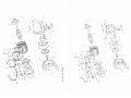
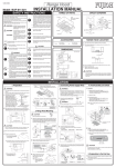
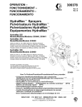
•:i~”
•i:
i_%.’b.#’iIi_I
~
ii~Ii’%.
~
i~~.%.flI
/
4”
IbjF%~.r
II-—
I%JF%V’%4
~1b
~ •diI.’..
Owner’s manual
Mode d’emploi et norme d’entretien
Bedienungsanweisung
Gebruiksaanwijzing
Instrucciones para el uso
Uso e manutenzione
Usc e manutenção
Bruksanvisning
/
Käyttöohje
/L~AD~R/
________
E
PUMPS
GB
LEGEND
•F
1. lnletlsuction pipe
2. Outlet/pressure pipe and
filling screw
3. Discharge screw
4. Pressure switch
5. Tank valve
NL
OMSCHEIJVING
E
1. Zuigaansluiting
2. Persaansluiting/
Afvuldop
3. Aansluiting ketel
4. Drukenschakelaar
5. Ventiel luchtkammer
P
i~—~
LEGENDA
S
1. Boca de aspiracao
2. Boca de envio
e carga de água
3. Parafuso de descarga de agua
4. Pressostato
5. Vãlvula de depOsito
LEGENDE
D
LEGENDE
1. Orifice daspiration
2. Orifice de refoulementl
Bouchon damorçage
3. Vis a devisser pour purger
4. Pressostat
5. Valve du reservoir
1. Eingang
2. Ausgang und
Einfüllschraube
3. Ablal3schraube
4. Druckschalter
5. Kesseldruckventil
LEGENDA
LEGENDA
1. Boca de aspiraciOn
2. Boca de salida de carga
de agua
3. Rosca de descarga de agua
4. Presostato
5. Válvula del depOsito
1. Boçca di aspirazione
2. Bocca di mandata
e carico acqua
3. Vite scarico acqua
4. Pressostato
5. Valvola del serbatoio
TECKENFORKLARING
1. Insugningshal
2. Uppfordringshal
Hal for vattenintag
3. Skruv for tOmning av vatten
4. Tryckvakt
5. Tankens ventil
SF
SELITYS
1. lmusuutin
2. SyOttosuutin
Veden tayttosuutin
3. Veden tyhjennysruuvi
4. Pressostaatti
5. SäiliOn venttilli
a.
Warning: Before the assembly and starting absolutely read this service manual.For safety
reasons people that hasn’t read the instructions must not use the pump.. The under 16
must not use the pump and must be kept away from connected pumps.
ATTENTION - IMPORTANT!!! Always unplug the pump before working on it.
Safety measures. Important Read attentively
-
The user is responsible towards third parties, for all that involves the pump utilization (electrical and hydraulic
equipment etc.) in observance of the local set of rules concerning safety and installation. Before the setting at work
it must be checked by a skilled electrician, that the requested safety measures are present. For the household
utilization of electropumps it is compulsory to install on the electric system a IAn = 30 mA safety switch (life protec
tor). Check the voltage (230 V a.c.). The directions carried out on the specification label must correspond with the
electric system specifications. In case of utilization in swimming-pools or ponds follow the rule VDE 0100 sect. 702.
Consult your electrician.
The pump must never work neither waterless nor with the delivery cock completely closed.The pump must
be utilized with clear water always below the 35°C.
Before carrying out any pump maintenance or cleaning operation, always disconnect the electrical plug.
The feeding cable can be replaced only with a cable of the type HO7RN-F or with a similar one.
Do not raise, carry or fix the pump from the connecting electric cable.
Before the utilization check if the connecting cable and the electric pin are damaged.
The pump is an electric apparatus and such a device must be protected against moisture.
Check that the connections to the electric taps are sheltered from floods, avoid that the pump is exposed to the
water direct jet, do not dip the pump into the water.
For a possible pump breakdown the repair must be carried out by authorized workshops only and original spare
parts only must de employed.
We let you know that for damages originated from:
a) not appropriate repairs not carried out by authorized service stations
b) parts replaced with not original spare parts
We are not responsible!
For the accessories are valid the same directions.
a) The pump does 1) No mains voltage.
not run.
2) Shaft blocked.
1) Check the voltage and/or the plug,
2) Unplug the pump. Disassemble and with a
screwdriver rotate the shaft and clean the pump.
b) The pump runs
but does not,deliver.
1) Air in the pump housing, no water
in pump .
body
.
2) Air bubbles in the suction pipe.
1) Unplug the pump. Take out discharge pipe; shake
the pump and suction pipe. Fill up pump housing
with water; fit discharge pipe and switch on the
pump.
2) Verity that suction pipe and fittings are fixed tight
and that water level is not below the pump level.
c) Thermal overload protector
switches off the
pump.
1) Voltage does not correspond to
indications shown on rating plate.
2) A solid blocked impeller.
3) Pump ran with hot water.
4) Pump ran dry or discharge tap was
closed.
1) Unplug the pump and remove the cause of the
overheating.Wait until thermal protector switches
back on.
*d) Pump switches 1) Pressure in the reservoir too little.
on incorrectly.
1) Pressure max. 1,5 bar.
2) Re-fill through filter valve.
*
e) Quantity being
conveyed too
little or none at
all.
1) Max. suction level exeeded. Dirty
suction filter.
2) Water level low. Air in the puma
housing.
1)
2)
3)
4)
5)
*
f) The pump startS
and stops
irregulary or
continously.
1) The pressure in the tank is not
sufficient or the membran is broken,
1) Increase the pressure up to 1,5 bar through the
tank valve or replace the membran.
Starting operations
Check the max. suction level.
Clean the suction filter.
Check that the suction valve is below water.
Release air by loosening the hose connectors.
Refil the pump housing with water via the filter
plug
Before installing and operating the pump it is absolutely necessary to carry out the following operations:
a) The diameter of the suction and delivery pipes should correspond to the diameter of the connections of the
pump housing (25 mm) (see point 1 and 2). Do not use any metal connections directly on the pump.
b) Fit the suction pipe with the foot valve to the pump (at point nr. 1), avoiding siphons, counterslopes and stand
the pump on solid, flat level ground.
c) Fit the delivery pipe at point nr. 2.
d) Before operating for the first time, the pump must be filled to the top with water through the delivery connection.
The filling operation must be carried out very slowly. Wait few minutes until air comes out an fill again to the top.
Before operating the pump check that the voltage correspond to the indications shown on the rating plate.
e) Put into operation the pump and wait the suction of the water. If nothing occurs after 2-3 minutes, switch off the
pump, unplug and repeat the whole operation (from point d).
Only for ~comatic)1noxmatic
The pressure switch must be always set as follows:
-
Mm. 2 Atm - Max. 3 Atm (lnoxmatic 100)
Mm. 2 Atm - Max. 3,5 Atm (Ecomatic 110)
Mm. 2,5 Atm - Max. 4 Atm (Ecomatic/lnoxmatic 120-130)
The tank must be always set at max. 1,5 Atm. Pressure should be cheded from time to time. If necessary refill with
air the tank thru its valve (point 5) and reset at 1,5 Atm.
Guarantee
This product is guai~nteed for a period of 12 months. The garantee covers exclusively material and manufacturing
faults. Damage which occurs because of misuse or from not following the instructions are not covered by guaran
tee.
*
Only for Ecomaticllnoxmatic
~ E’c
-
~
~
“
.-‘ ... -
‘ck~L’~’~4.
•j,
,~.‘
The Leader Pumps Group S.p.A. - Via Bonanno Pisano, 1 - 56031 Bientina (P1) Italy, hereby declares on its
own full responsibility that the products to which this declaration refers comply to the following EEC health and
safety regulations:
8913921EWG 8913361EWG 731231EWG
By way of comparison, within the ambit of the above stated EEC health and safety standards, the following stand
ards and/or technical specifications have been referred to:
EN 60 335-1 1988-89
EN 55014 87-90-1/2
EN 60 335-2-41 1990-91
DIN-VDE 0700-1
EN 292-1 EN 292-2 EN 50081-2
EN 50082-2 EN 55014-1/2
EN 60555 Teil 2 u. 3
DIN-VDE 0700-2-41
Michele Leone
Technical &
Blentina,
31/03/98
Quality Dept
Leader Pumps
Group S.p.A.
\
a
\
\\
\
\
~1
\.
\
\
a
\
\
.3
0~
\
\
~ A
V.)
C.)
F~)
-‘
\
z
\
0
><
C
m
m
C)
0
\
01
—I
C—
m
H
0
“3
0
0
C.)
a
C.)
0,
C.)
cC