1
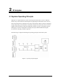
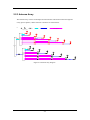
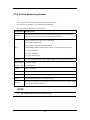
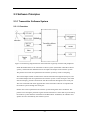
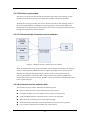
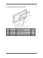
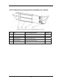
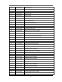
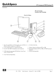
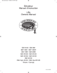
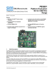
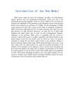
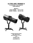
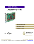
TMS-6016 Telemetry Monitoring System Service Manual Intellectual Property Statement SHENZHEN MINDRAY BIO-MEDICAL ELECTRONICS CO., LTD. (hereinafter called Mindray) owns the intellectual property rights to this product and this manual. This manual may refer to information protected by copyrights or patents and does not convey any license under the patent rights of Mindray, nor the rights of others. Mindray does not assume any liability arising out of any infringements of patents or other rights of third parties. and are the registered trademarks or trademarks owned by Mindray in China and other countries. I Preface Manual Purpose This manual provides detailed information about the assembling, dissembling, testing and troubleshooting of the equipment to support effective troubleshooting and repair. It is not intended to be a comprehensive, in-depth explanation of the product architecture or technical implementation. Observance of the manual is a prerequisite for proper equipment maintenance and prevents equipment damage and personnel injury. Intended Audience This manual is for biomedical engineers, authorized technicians or service representatives responsible for troubleshooting, repairing and maintaining the defibrillator/ monitors Revision History This manual has a revision number. This revision number changes whenever the manual is updated due to software or technical specification change. Contents of this manual are subject to change without prior notice. Version number Release time: October 2008 3.0 © 2005-2008 Shenzhen Mindray Bio-Medical Electronics Co., Ltd. All rights reserved. II Contents 1 Safety ................................................................................................................................. 1-1 1.1 Safety Information .......................................................................................................... 1-1 1.1.1 DANGER ........................................................................................................... 1-2 1.1.2 Warnings............................................................................................................. 1-2 1.1.3 Cautions ............................................................................................................. 1-2 1.1.4 Notes .................................................................................................................. 1-2 1.2 Equipment Symbols ........................................................................................................ 1-3 2 Principles........................................................................................................................... 2-1 2.1 System Operating Principle............................................................................................. 2-1 2.2 Hardware Operating Principles ....................................................................................... 2-2 2.2.1 Transmitter ......................................................................................................... 2-2 2.2.2 Receiver ............................................................................................................. 2-3 2.2.3 Antenna Array .................................................................................................... 2-5 2.2.4 Central Monitoring System ................................................................................ 2-6 2.3 Software Principles ......................................................................................................... 2-7 2.3.1 Transmitter Software System ............................................................................. 2-7 2.3.2 Receiver System Software ................................................................................. 2-8 3 Configuring Functions ..................................................................................................... 3-1 3.1 Overview......................................................................................................................... 3-1 3.2 Configuration Method..................................................................................................... 3-1 4 Structure and Troubleshooting ....................................................................................... 4-1 4.1 Exploded View of a Transmitter...................................................................................... 4-1 4.2 Structure of a Receiver.................................................................................................... 4-3 4.2.1 Exploded view of a receiver............................................................................... 4-3 4.2.2 Front cover assembly of a receiver..................................................................... 4-6 4.2.3 Amplifying and branching assembly of a receiver ............................................. 4-7 4.2.4 Power assembly of a receiver............................................................................. 4-8 4.2.5 4-channel receiving module assembly of a receiver........................................... 4-9 4.3 Troubleshooting ............................................................................................................ 4-10 4.3.1 Troubleshooting table....................................................................................... 4-10 5 List of Materials ............................................................................................................... 5-1 1 FOR YOUR NOTES 2 1 Safety 1.1 Safety Information DANGER z Indicates an imminent hazard that, if not avoided, will result in death or serious injury. WARNING z Indicates a potential hazard or unsafe practice that, if not avoided, could result in death or serious injury. CAUTION z Indicates a potential hazard or unsafe practice that, if not avoided, could result in minor personal injury or product/property damage. NOTE z Provides application tips or other useful information to ensure that you get the most from your product. 1-1 1.1.1 DANGER There are no dangers that refer to the product in general. Specific “Danger” statements may be given in the respective sections of this manual. 1.1.2 Warnings WARNING z All installation operations, expansions, changes, modifications and repairs of this product are conducted by Mindray authorized personnel. z There is high voltage inside the system. Never disassemble the system before it is disconnected from the AC power source. z The system must be connected to a properly installed power outlet with protective earth contacts only. If the installation does not provide for a protective earth conductor, disconnect it from the power line. z Dispose of the package material, observing the applicable waste control regulations and keeping it out of children’s reach. 1.1.3 Cautions CAUTION z Make sure that no electromagnetic radiation interferes with the performance of the system when preparing to carry out performance tests. Mobile phone, X-ray equipment or MRI devices are a possible source of interference as they may emit higher levels of electromagnetic radiation. z Before connecting the system to the power line, check that the voltage and frequency ratings of the power line are the same as those indicated on the system’s label or in this manual. z Protect the system from damage caused by drop, impact, strong vibration or other mechanical force during servicing. 1.1.4 Notes NOTE z Refer to Operation Manual for detailed operation and other information. 1-2 1.2 Equipment Symbols Attention: Consult accompanying documents. Power on Power off Alternating current (AC) Type CF applied part. The unit displaying this symbol contains an F-type isolated (floating) patient part providing a high degree of protection against shock, and is suitable for use during defibrillation. Equipotential terminal Non-ionizing electromagnetic radiation Network connector Antenna interface Communication status CE marking ESD warning symbol for Electrostatic sensitive devices. 1-3 FOR YOUR NOTES 1-4 2 Principles 2.1 System Operating Principle TMS-6016 is a digital telemetry system consisting of the transmitter, receiver, CMS and antenna array. The transmitter sends the patient’s physiological information to the receiver, which then transmits the information received to the telemetry CMS for analysis, displaying, storage and printing. The transmitter is attached to the patient, whereas the receiver is used together with the telemetry CMS. The TMS-6016 telemetry system is intended to monitor and display a fixed set of parameters including ECG, SpO2, HR and PR under hospital environments. The SpO2 module is optional. The following is a diagram illustrating the operating principle of the whole system: Figure 2-1 system principle diagram 2-1 2.2 Hardware Operating Principles 2.2.1 Transmitter 2.2.1.1 Principle diagram Figure 2-2 Transmitter principle diagram 2.2.1.2 Overview The transmitter mainly consists of the ECG signal amplifying circuit, power supply circuit, MCU, audible and visual alarm indication circuit, wireless transmission module, SpO2 connector, etc. The ECG amplifying circuit provides the amplified ECG signals for three channels, which are respectively called Lead I, II and V. The MCU circuit is the core of the transmitter, enabling the following functions: Button signal detection A/D conversion of ECG analog signals Audible and visual alarm indication drive SpO2 connector Status detection, such as ECG overload detection, lead off detection, PACE detection, etc. ECG data processing Wireless transmission module control Baseband signal generation The Wireless transmission module is to send ECG data, SpO2 data and status information out .The shielding layer of the ECG lead is the transmitter antenna. 2-2 2.2.2 Receiver 2.2.2.1 Principle diagram Figure 2-3 Receiver principle diagram The receiver comprises the AC/DC power source, power adapter board, amplifying and branching module, 4-channel receiver, LED board, main control board and network interface board. 2.2.2.2 AC/DC Source The AC/DC source is to convert the externally inputted AC source into a 9V DC by means of isolation. The inputted AC voltage range is from 90V to 264V, and the outputted voltage/current is 9V/6.5A. 2.2.2.3 Power Adapter Board The power adapter board is to drop the 9V DC coming from the AC/DC source to a 5V DC and then output it with the 9V DC. 2-3 2.2.2.4 Amplifying and branching Module The amplifying and branching module is to amplify, filter and branch RF signals. The module allows two amplifying, filtering & branching circuits with circuit parameters in full symmetry. Each circuit amplifies, filters and branches the RF signals received by its corresponding antenna and then outputs 4 channels of RF signals. Therefore, there are a total of 8 channels of RF signals, which are then sent to the 4-channel receiver for processing. The 9V DC linearly drops down to an 8V DC, which then goes to the amplifying and branching module. The antenna array is shared by all receiving modules. Therefore, in order to compensate for the branching attenuation of the signal, an LNA (low noise amplification) is added before the branch divider. Besides, to avoid that the LNA is blocked by strong out-band signal interference, filtering circuits shall be added in front of and behind the LNA. 2.2.2.5 4-Channel Receiver The 4-channel receiver divides the two channels of antenna signals coming from the amplifying and branching module into four channels of RF signals through the 4-channel branch divider. The MCU of the 4-channel receiving board will estimate the received signal strength (RSSI) and then select the corresponding antenna signals through the antenna switch. The selected signals will be respectively sent to the receiving modules for filtering, amplifying, mixing, filtering and demodulating. The demodulated 4-channel analog signals will then be sent to the MCU system for clock and data regenerating. The regenerated data is packed by CPU and then delivered via the asynchronous serial port to the main control board for processing. The 9V DC linearly drops down to an 8V DC, which is then stabilized into a 5V and a 3.5 V supplying power for the 4-channel receiver. 2.2.2.6 Main Control Board After receiving the data coming from the 4-channel receiving board, the main control board will pack them and then delivers them to the CMS through the Ethernet. The speaker of the main control board will give a short beep when the initialization is over, and will beep continuously when an initialization failure or a hardware fault occurs. 2.2.2.7 LED Board The LED board has two green LEDs, respectively indicating the power status and the communication status of the receiving module. 2.2.2.8 Network Interface Board The interface between the main control board and Ethernet consists of the network isolating transformer and interface connector. 2-4 2.2.3 Antenna Array The antenna array consists of multiple external antennas which interconnect through the 8-way power splitters, cables and TNC connectors as shown below. Note: Antenna Adapter TNC-JKW Adapter TNC-KK K Cable-Connector-JJ Cable-Connector-JJ Cable-Connector-JJ 天线3 天线3 天线3 天线3 天线3 8-way power divider 天线3 天线3 天线3 Receiv er 天线3 天线3 天线3 天线3 天线3 8-way power divider 天线3 天线3 天线3 Figure 2-4 Antenna array diagram 2-5 2.2.4 Central Monitoring System The computer of the CMS should be highly reliable and stable. The commercial computer we recommend is HP-DC7800. Recommended configurations of DC7800 are: Components Requirements System Meet the IEC60950 requirements defined for ITE equipment, and comply with CE low voltage directives (LVD) and EMC directives. DualCore Intel Core 2 Duo E6750, 2660MHz 2G minimum DDR II-667 80G minimum, 7200rpm SATA Hard Disk Host 100M/100M/1000M Network adapter, Base-T, Ethernet 802.3, RJ45 port 2 or more USB ports 1 or more serial ports 1 or more parallel ports Display 17"LCD minimum, 1280×1024, length: width 4:3 or 5:4, with CE marking. Dual-display graphic card Minimum 256M; Mouse With CE marking. Keyboard With CE marking. Recorder Mindray thermal array, serial port. Printer HP LaserJet, supporting A4 and Letter paper. Speaker Built in the computer or the display. Give alarm tones (45 to 85 dB), alarm tones comply with IEC60601-1-8. NVADIA 8500 NOTE z The configuration above is for reference only. 2-6 2.3 Software Principles 2.3.1 Transmitter Software System 2.3.1.1 Overview Figure 2-5 Interfacing diagram between the transmitter single-chip software and peripherals Inside the dashed frame is the transmitter software system (hereinafter called the software system), and outside the dashed frame are the inputs and outputs of the software system. The patient’s ECG data are inputted into the software system by means of sampling. The external SpO2 module communicates with the transmitter through the serial port, and the collected SpO2 data are inputted into the software system via the serial port. The CMS and external SpO2 module communicate with the transmitter through the same serial port. The user commands and online upgrade files of the transmitter software are inputted into the software system through this serial port. Patient calls can be inputted into the software system through the nurse call button. The patient’s ECG and SpO2 parameter signals and the transmitter’s status data are processed by the software system and then transmitted to the RF module. In addition, the indicator and speaker are also controlled by the software system. 2-7 2.3.1.2 Transmitter system task The transmitter collects the patient’s ECG and SpO2 signals, and then detects the pace pulse, SpO2 and other status information in them by amplifying and digitalizing them, and finally sends the detected information to the receiver through wireless channels. The transmitter supports the auto detection of 3-lead or 5-lead leadwire, lead off detection and PACE detection. It also supports the external SpO2 module though the SpO2 connector, through which the CMS can perform the parameter configuration and online software upgrade to the transmitter. The transmitter also enables these functions including battery voltage detection, call button detection and event button detection. Besides, it supports audible and visual alarms and enables the standby mode. 2.3.2 Receiver System Software 2.3.2.1 Overview Figure 2-6 Receiver system software diagram Inside the dashed frame is the system software of the main control board (hereinafter called the software system), and outside the dashed frame is the inputs and outputs of the software system. The data coming from the 4-channel receiver are sent to the software system through the serial port. The main control board and receiver controller communicate through the serial port. The main control board directly controls the LED indicator through the I/O port and communicates with the CMS through the Ethernet. 2-8 2.3.2.2 Receiver system task The receiver receives data from boards, descrambles data, analyzes the integrity of data, generates relevant alarm messages and sends them together with data to the CMS. Through the receiving controller, the receiver obtains and controls the operating status of the receiving demodulator, including the operating frequency and signal strength of the demodulator. After detecting the operating status, the receiver will give prompt information through the communication status indicator. 2.3.2.3 Overview of the 4-channel receiver software Figure 2-7 Diagram for the 4-channel receiver software Inside the dashed frame is the receiving module control software (hereinafter call software system), and outside the dashed frame are the inputs and outputs of the software system. Through the serial port and signal line, the software system communicates with the receiving demodulator, resolves the data coming from the data-generating module and controls the antenna system via switch. Besides, it also communicates with the main control board via the serial port. 2.3.2.4 4-channel receiver software task The 4-channel receiver mainly undertakes the following tasks: Recover and resolve the wireless transmission space protocol; Configure frequency for the 4-channel receiver on the receiving board; Collect the RSSI from the 4-channel receiver on the receiving board; Select antenna according to the received signal strength; Collect the status information of the 4-channel receiver on the receiving board; Carry out the communication with the main control board. 2-9 FOR YOUR NOTES 2-10 3 Configuring Functions 3.1 Overview You can configure the frequencies of the transmitter and receiver through the TMS-6016 telemetry monitoring system, so that the interfered frequency point can be easily evaded when there is interference with the transmitting frequency point. As a result, the stability and reliability of the system is improved. NOTE z The configuration of telemetry system may cause malfunction of the product. Please do this with caution. z Please use new batteries during the configuration, avoiding invalid configurations due to power-off of batteries. The transmitter cannot be configured in case the batteries are not loaded or the battery voltage is too low. 3.2 Configuration Method 1. Connect one end of the dedicated configuration cable to the serial port 1 (COM1) on the PC, and the other end to the SpO2 connector on the transmitter. 2. Click the “System Setup” icon at the lower right corner of the screen of the CMS. Figure 3-1 User screen 3-1 3. Click the “User Setup” icon. A dialog box will be displayed asking you to input user password. Figure 3-2 System Setup Tab Sheet 4. Input the correct user password. The following screen will be displayed. Figure 3-3 The screen appeared after inputting the correct password 3-2 5. Click the “Telemetry” icon at the upper right corner of the screen. the system will enter the configuration screen as below. Figure 3-4 Configuration screen 6. Select an appropriate frequency segment from “Select Freq. Range” area. 7. Select a channel correspond to the transmitter (here channel 13 is selected) and click the “Program” button at the lower right corner. The following dialog box will be displayed as below: Figure 3-5 Programming screen 3-3 8. After enter this dialog box, input the frequency you want to set, and then you can press either the “Ok” button to start programming or the “Cancel” button to exit the programming. 9. After the programming succeeds, the following message “frequency is set successfully” will be displayed. 10. Click “Ok” to close the current dialog box. So far the programming of a pair of transmitter and receiver modules is finished. 11. If you want to program another pair of transmitter and receiver module, repeat the above step 6-10. 3-4 4 Structure and Troubleshooting 4.1 Exploded View of a Transmitter Figure 4-1 Exploded view of a transmitter 4-1 No P/N Name and Specifications Quantity 1 0152-20-39707 silicone stopper 1 2 0152-20-39704-51 upper cover 1 3 0152-20-39711 stripper rubber 1 4 0152-30-39700 main board of the transmitter 1 5 0152-20-39709 left shoe plate 1 6 M04-051045--- cross pan head screw (M2.5×6) 6 7 0152-20-39715 anti-dazzling screen 1 8 0152-20-39756 label on the transmitter 1 9 0000-20-10953 neutral blank label(35*9mm) 1 10 0152-20-39708 silicone key 1 11 0152-20-39705 shell 1 12 0152-20-39716 positive reed 1 13 0152-20-39717 negative reed 1 14 0152-20-39706 battery door 1 15 0152-20-39713 plain washer 2 16 0152-20-39718 positive and negative reeds of the battery 1 17 0152-20-39712 shielding cover 1 18 0152-20-39763 battery compartment label 1 19 M04-006005 cross recessed countersunk head screw(M2.0×4) 2 20 0152-20-39714 RF shielding cover of the transmitter 1 21 0152-30-39770 RF board (420-440) 1 22 0152-20-39710 right shoe plate 1 4-2 4.2 Structure of a Receiver 4.2.1 Exploded view of a receiver 4.2.1.1 Exploded view –1 of a receiver Figure 4-2 Exploded view –1 of a receiver 4-3 4.2.1.2 Exploded view –2 of a receiver Figure 4-3 Exploded view –2 of a receiver 4-4 No P/N Name and Specifications Quantity 1 0152-20-39747 main bracket 3 of the receiver 1 2 0152-20-39746 main bracket 2 of the receiver 1 3 9210-30-30152 Ethernet interface board 1 4 M04-002505--- cross pan head screw M3×6 2 5 9210-30-30150 9210 main control board 1 6 900E-20-04894 dust washer1 1 7 M04-021003--- plain washer GB97.26 1 8 M04-004504--- spring washer BF93 6 4 9 M04-004401--- stainless steel hexagon nut M6 1 10 0152-20-39744 bottom plate of the receiver 1 11 0152-30-39805 4-channel receiver (430-435) 4 12 M04-000405--- cross recessed countersunk screw M3×8 21 13 0152-30-39729 front cover assembly of the receiver 1 14 0152-30-39749 upper cover of the receiver 1 15 0152-30-39724 power adapter board 1 16 0152-30-39738 power assembly of the receiver 1 17 M04-000603--- lock washer, nickle plating 1 18 0152-00-39745 main bracket 1 of the receiver 1 19 0152-20-39732 rubber foot of the receiver 1 20 0152-30-39834 amplifying and branching assembly of the receiver (420-470) 1 21 M04-004012--- cross pan head screw with washer M3×6 41 22 0030-10-13055 Filter power 115/250VAC6A panel mount 1 23 0509-20-00098 ground pole 1 4-5 4.2.2 Front cover assembly of a receiver Figure 4-4 Front cover assembly of a receiver No P/N Name and Specifications Quantity 1 0152-20-39730 front cover of the receiver 1 2 0152-20-39748 main bracket 4 of the receiver 1 3 0152-30-39726 LED indicator board 1 4 M04-004012--- cross pan head screw with washer M3×6 4 4-6 4.2.3 Amplifying and branching assembly of a receiver Figure 4-5 Amplifying and branching assembly of a receiver No P/N Name and Specifications Quantity 1 0152-20-39735 upper cover of the amplifying and branching assembly 1 of the receiver 2 M04-002505--- cross pan head screw M3×6 9 3 M39-000143--- antenna socket 2 4 0152-20-39736 lower cover of the amplifying and branching assembly 1 of the receiver 5 0152-30-39720 amplifying and branching board(420-470) 1 6 M40-A00014--- bushing-type capacitor 1 7 M39-000140--- SMA RF socket 8 8 M04-002405--- cross pan head screw M2×6 66 4-7 4.2.4 Power assembly of a receiver Figure 4-6 Power assembly of a receiver No P/N Name and Specifications Quantity 1 0152-20-40046 power cover of the receiver 1 2 0000-10-11152 Power module AC/DC 90-264VAC 9VDC 1 3 M04-004012--- cross pan head screw M3×6 4 4-8 4.2.5 4-channel receiving module assembly of a receiver Figure 4-7 4-channel receiving module assembly of a receiver No P/N Name and Specifications Quantity 1 M04-051121--- cross pan head screw M2.5×8 12 2 0152-20-39743 rear plate of the receiver module 1 3 0152-20-39741 receiver module cavity 1 4 0152-30-39722 4-channel receiving board 1 5 0152-20-39742 front plate of the receiving board 1 4-9 4.3 Troubleshooting 4.3.1 Troubleshooting table Alarm message Description Processing method Battery voltage low The battery energy of the transmitter is about to use up. Replace the battery of the transmitter. No RF signal The receiver hasn’t received valid data for 5 s. Check if the battery energy of the transmitter is used up; Check if the transmitter enters the power saving mode; Check if the patient walks out of the covering range; Check if the antenna array cables are properly connected; Check if the transmitter is installed with the lead wire serving as antenna; RF interference The transmitter has received 3 erroneous data frames. Check if the patient is at the margin of the covering range, or inside of the elevator, or behind the reinforced concrete wall; Check if there is an intense RF interference source; Wrong ID The receiver has received the data transmitted by the transmitter, but the ID code doesn’t belong to this system. Check if there is another telemetry system nearby, and contact the maintenance technicians to reconfigure the frequency points. Offline The CMS and the receiver cannot set up the networking connection. Check if the receiver is turned on; ECG noise The ECG waveforms are superimposed with noise interference. Check if the ECG leadwire is intertwined with cables of other devices. ECG signal saturation The transmitter detects that signals of the ECG amplifying channel are saturated and overloaded. Check the quality of the ECG electrodes; 4-10 Check if the networking cable between the receiver and the CMS is properly connected. Check the connection of the ECG electrode and skin; SpO2 Out of Track The SpO2 signal is too low or too weak. Check the patient’s condition and change the sensor application site. If the error persists, replace the sensor. Transmitter key error The transmitter detects that a key has been pressed for over 10 s. Check if the key is pressed by an foreign object or jammed. Transmitter or SpO2 module restarting repeatedly. The transmitter’s battery capacity is to be depleted. Replace the transmitter’s battery. Receiver Fault An error occurred to the receiver. Restart the receiver. 4-11 FOR YOUR NOTES 4-12 5 List of Materials NOTE z No Here we list most replaceable parts. If you need more parts, please contact our Customer Service Department. P/N Material Description 1. 0030-10-13055 power filter 2. 0152-20-39732 rubber foot of the receiver 3. 0152-20-39744 bottom plate of the receiver 4. 0152-20-39745 main bracket 1 of the receiver 5. 0152-20-39746 main bracket 2 of the receiver 6. 0152-20-39747 main bracket 3 of the receiver 7. 0152-20-39749 upper cover of the receiver 8. 0152-20-39753 output wire of the power adapter board 9. 0152-20-40047 input wire of the power adapter board 10. 0152-20-39731 input wire of the power module 11. 0152-20-39764 network connection cable 12. 0152-30-39724 power adapter board 13. 0152-20-39730 front cover of the receiver 14. 0152-20-39748 main bracket 4 of the receiver 15. 0152-30-39726 LED indicator board 16. 0152-30-39734 amplifying and branching assembly of the receiver (185-205) 17. 0152-30-39834 amplifying and branching assembly of the receiver (420-470) 18. 0152-20-39750 power wire of the amplifying and branching assembly 19. 0000-10-11152 Power module AC/DC 90-264VAC 9VDC 20. 0152-20-40046 power cover of the receiver 21. 9210-30-30150 main control board 22. 9210-30-30152 network connection board 23. 0000-10-10962 flexible cable with 10 pins and spacing 0.5mm 24. 0152-20-39704 upper cover 25. 0152-20-39705 shell 26. 0152-20-39706 battery door 5-1 27. 0152-20-39707 silicone stopper 28. 0152-20-39708 silicone key 29. 0152-20-39709 left shoe plate 30. 0152-20-39710 right shoe plate 31. 0152-20-39711 stripper rubber 32. 0152-20-39712 shielding shell 33. 0152-20-39713 plain washer 34. 0152-20-39715 anti-dazzling screen 35. 0152-20-39716 positive reed of the battery 36. 0152-20-39717 negative reed of the battery 37. 0152-20-39718 positive and negative reeds of the battery 38. 0152-30-39700 transmitting main board 39. 0152-20-39786 connecting wire of ceramic speaker 40. M39-000408--- connector-- 4-pin plastic PCB socket 41. 0152-30-39768 main unit of the transmitter (189-196) 42. 0152-30-39838 main unit of the transmitter (420-440) 43. 0152-30-39839 main unit of the transmitter (440-470) 44. 0152-30-39767 transmitter assembly 45. 0152-30-39769 RF module assembly (189-196) 46. 0152-30-39836 RF module assembly (420-440) 47. 0152-30-39837 RF module assembly (440-470) 48. 0000-10-10967 RF MODULE 425-430MHz 49. 0000-10-10968 RF MODULE 430-435MHz 50. 0000-10-10969 RF MODULE 189.75-191.75MHz 51. 0000-10-10970 RF MODULE 194-196MHz 52. 0000-10-10988 RF MODULE 420-425MHz 53. 0000-10-10989 RF MODULE 435-440MHz 54. 0000-10-10990 RF MODULE 440-445MHz 55. 0000-10-10991 RF MODULE 445-450MHz 56. 0000-10-10992 RF MODULE 450-455MHz 57. 0000-10-10993 RF MODULE 455-460MHz 58. 0000-10-10994 RF MODULE 460-465MHz 59. 0000-10-10995 RF MODULE 465-470MHz 60. 0152-20-39741 receiver module cavity 61. 0152-20-39743 rear plate of the receiver module 62. 0152-20-39751 serial port wire 5-2 63. 0152-30-39722 4-channel receiving board 64. 0152-20-39742 front plate of the receiver module 5-3 FOR YOUR NOTES 5-4 P/N: 0152-20-39885(3.0)