1
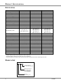
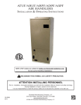
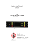
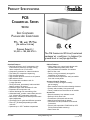
PRODUCT SPECIFICATIONS
PCB
COMMERCIAL SERIES
50 Hz
SELF-CONTAINED
PACKAGE AIR CONDITIONER
7½, 10,
AND 15 TON
[26.4 kW to 52.8 kW]
COOLING CAPACITY:
90,000
TO
180,000 BTU/H
The PCB Commercial 50 Hz self-contained
packaged air conditioner is designed for
ground-level or rooftop application.
Standard Features
• Dual high-efficiency scroll compressors with
internal motor protection (2-stage cooling;
three compressors on 15-ton units)
• Compressor grommets for vibration isolation
• Time delay for compressor sequencing
• Fully charged systems
• High- and low-pressure controls on all systems
• Mild ambient switch
• Two independent condenser coils for
2-stage operation
• Totally enclosed, permanently lubricated ballbearing outdoor fan motors
• Enhanced copper tube/aluminum fin coils
• Expansion valve evaporator coil
• Vertical discharge with removable grilles
• Galvanized steel, powder-coated drain pan with
3/4” (19mm) NPT condensate connection
• Belt-driven, variable-pitch sheave permits multispeed adjustment
• Centrifugal fan for quiet and efficient operation
• Filters (2” [50.8mm] disposable) provided
with unit
• Operates up to 125°F ambient temperature
SS-PCB50
Cabinet Features
• Heavy-gauge, zinc-coated steel cabinet with
weather-resistant powder-paint finish
• Fully insulated with blankets of insulation
• Built-in filter rack
• Factory wiring conveniently arranged for
installation of accessories
• Control box and compressors easily accessible
from side access panels
Accessory Heat Kit Features
• Control circuitry arranged to readily
permit staging
• Rust-resistant nickel chromium heating elements
• Primary and secondary limit protection
• Factory-installed one-time fuses on all models
Accessories
• Room thermostat; Low-ambient control
• Rooftop Lift Kit; Roof curb
• Economizers (horizontal and vertical)
• Manual/motorized fresh air damper
• Horizontal Duct Kit (Downflow to Horizontal
Conversion)
• Electric heat capacities 15 kW-30 kW @ 415V
50 Hz (field-installed accessory)
• Panel Louver Kit
www.goodmanmfg.com
6/06
Supersedes 12/05
PRODUCT SPECIFICATIONS
SPECIFICATIONS
Total Cooling - BTU/h (kW)
Sensible Cooling - BTU/h¹ (kW)
EER²
Indoor Blower (Qty.)
Type
Size - D x W (mm)
Motor Horsepower (kW)
Indoor CFM Nominal (L/S)
Evaporator Coil (Qty.)
Face Area - Ft.² (m²)
Rows/FPI (FPM)
Tube Diameter (mm)/Material
Filter Size/Qty. (mm)
Outdoor Fan (Qty.)
Fan Diameter (mm)
Motor Horsepower (kW)
Outdoor CFM Nominal (L/S)
Condenser Coil (Qty.)
Face Area Total - Ft.² (m²)
Rows/FPI (FPM)
Tube Diameter (mm)/Material
Number of Compressors
Volts-Phase
Compressor RLA/LRA
Blower FLA - Indoor/Outdoor
Minimum Circuit Ampacity³
Maximum Fuse Size
Ship Weight - lbs. (kg)
PCB090-5
88,400 (25.9)
67,100 (19.7)
8.9
2
Belt
12 x 12 (305 x 305)
2 (1.49)
3000 (1416)
1
9.3 (0.86)
3/16 (630)
3/8” (9.5)/Copper
PCB120-5
118,600 (34.8)
89,200 (26.1)
9.7
2
Belt
12 x 15 (305 x 381)
3 (2.24)
4000 (1888)
1
14.0 (1.3)
3/16 (630)
3/8” (9.5)/Copper
PCB180-5
172,000 (50.4)
131,000 (38.4)
8.5
2
Belt
12 x 15 (305 x 381)
5 (3.73)
5600 (2643)
1
14.0 (1.3)
3/16 (630)
3/8” (9.5)/Copper
25” x 25” x 2”
(635 x 635 x 8.51)/3
16” x 25” x 2”
(406 x 635 x 51)/3
20” x 25” x 2”
(508 x 635 x 51)/3
16” x 25” x 2”
(406 x 635 x 51)/3
20” x 25” x 2”
(508 x 635 x 51)/3
2
24” (610)
1/2 (0.37)
4300 (2030)
1
2
24” (610)
1/2 (0.37)
6100 (2880)
1
4
22” (559)
1/2 (0.37)
7000 (3300)
1
15.6 (1.45)
2/21 (827)
3/8 (9.5)/Copper
2
380-415-3
6.7/47.5
3.4/1.7
23.6
30
990 (449.5)
23.8 (2.21)
2/21 (827)
3/8 (9.5)/Copper
2
380-415-3
9.5/73.0
4.2/1.7
31.3
50
1215 (551.6)
23.8 (2.21)
3/16 (630)
3/8 (9.5)/Copper
3
380-415-3
9.5/73.0
7.3/1.7
49.5
60
1460 (662.8)
¹ Sensible capacity is gross, with no deduction for indoor motor heat
² BTU/Watt @ 80/67°F (26.7/19.4°C) inside - 95°F (35°C) outside air
³ Wire size should be in accordance with Local Electrical Codes. Extensive wire runs will require larger wire sizes.
NOMENCLATURE
PCB 090 - 5
ELECTRICAL DESIGNATOR
5 - 380/415 VAC, 3ph, 50Hz
NOMINAL COOLING CAPACITY
090 - 90,000 BTU/h
120 - 120,000 BTU/h
180 - 180,000 BTU/h
UNIT TYPE
PCB - Package Cool
2
SS-PCB50
PRODUCT SPECIFICATIONS
DIMENSIONS
All dimensions in inches and millimeters. Drawings are not to scale.
FIGURE 1. VERTICAL DISCHARGE
See curb details for connection of duct work to
curb. Duct work is not intended to be connected
to unit.
FIGURE 2. HORIZONTAL DISCHARGE
Note: The Horizontal Conversion Kit is required to convert
a factory duct configuration (downflow) to a horizontal
duct configuration, as shown in Figure 2.
SS-PCB50
UNIT SIZE
A - HEIGHT
B - SUPPLY AIR
C - RETURN AIR
090
36” (914 mm)
12½” (318 mm)
179/16” (446 mm)
120,180
52” (1321 mm)
20¼” (514 mm)
2513/16” (656 mm)
3
PRODUCT SPECIFICATIONS
ELECTRICAL CONNECTIONS
MODEL
B
PCB090-5
7⅞” (200 mm)
PCB120-5
23⅞” (606 mm)
PCB180-5
23⅞” (606 mm)
1– Main power entrance location (with electric heat
installed)
2– Control wiring entrance location
3– Main power entrance location (without electric heat
installed)
Note: Single-point wiring is available at location #1
when heat kit is installed. See installation instructions
for heat kits.
FIGURE 3. ELECTRICAL HEAT UNITS
ELECTRIC HEAT
ELECTRIC HEAT AIR TEMPERATURE RISE @ NOMINAL VOLTAGE
Heater Model
No. Stages
Output MBH (W)
2600 (1227)
CFM
&
(L/S)
2800 (1320)
22.5 (12.5)
33.6 (18.7)
3000 (1415)
21.0 (11.7)
31.4 (17.4)
-
3200 (1510)
19.7 (10.9)
29.4 (16.3)
39.3 (21.8)
3400 (1605)
18.5 (10.3)
27.7 (15.4)
37.0 (20.6)
3600 (1700)
17.5 (9.7)
26.2 (14.6)
34.9 (19.4)
3800 (1793)
16.5 (9.2)
24.8 (13.8)
33.1 (18.4)
4000 (1888)
15.7 (8.7)
23.5 (13.1)
31.4 (17.4)
4200 (1982)
15.0 (8.3)
22.4 (12.4)
29.9 (16.6)
4400 (2076)
14.3 (7.9)
21.4 (11.9)
28.6 (15.9)
4600 (2171)
13.7 (7.6)
20.5 (11.4)
27.3 (15.2)
4800 (2265)
13.1 (7.3)
19.6 (10.9)
26.2 (14.6)
5000 (2360)
12.6 (7.0)
18.8 (10.4)
25.2 (14.0)
5200 (2454)
12.1 (6.7)
18.1 (10.1)
24.2 (13.4)
5400 (2548)
11.6 (6.4)
17.4 (9.7)
23.3 (12.9)
5600 (2643)
11.2 (6.2)
16.8 (9.3)
22.5 (12.5)
5800 (2737)
10.8 (6.0)
16.2 (9.0)
21.7 (12.1)
6000 (2832)
10.5 (5.8)
15.7 (8.7)
21.0 (11.7)
NOMINAL VOLTAGE
HKCB20-4
HKCB30-4
HKCB40-4
4
HKCB20
HKCB30
HKCB40
2
2
2
67.5 (19.8) 101.3 (29.7) 135.0 (39.6)
24.2 (13.4) 36.2 (20.1)
-
FOR
-
@ 415V
14.9 kW
22.3 kW
29.7 kW
Temperature Rise =
Output Capacity - BTU/h
1.08 x ft³/min. Airflow
Note: Temperature rises must be calculated in other than nominal voltage conditions.
4. For altitudes over 2,000’, air temperature rise must be calculated
using the formula:
Temperature Rise =
Output Capacity - BTU/h
14.4 x ft³/Min. Airflow x Specific Weight of Air
5. Operation at less than nominal voltages must be de-rated by the
following factors: 415 volt-0.75; 380 volt-0.63.
ELECTRIC HEATER AVAILABILITY
HKCB
@ 480V
19.8 kW
29.7 kW
39.6 kW
Notes:
1. Maximum air temperature rise of 40°F (22.2°C) must not be
exceeded.
2. See Electric Heater Availability table for various unit sizes.
3. Air temperature rise is for total heating capacity: Temperature rises
at other conditions may be calculated by using the formula:
@ 380V
12.5 kW
18.7 kW
25.0 kW
Unit Size
7½
10
15
HKCB20
X
X
X
HKCB30
X
X
X
HKCB40
X
X
X
SS-PCB50
PRODUCT SPECIFICATIONS
FAN PERFORMANCE DATA
FIGURE 4. FAN CURVE - PCB 090
SUPPLY FAN PERFORMANCE - PCB090
CFM
2600
2800
3000
3200
3400
0.2
RPM
BHP
669
0.44
734
0.53
770
0.62
807
0.73
845
0.85
0.4
RPM
BHP
816
0.59
847
0.69
877
0.79
909
0.91
942
1.04
EXTERNAL STATIC PRESSURE
0.6
0.8
RPM
BHP
RPM
BHP
916
0.75 1004 0.92
944
0.85 1030 1.03
973
0.97 1053 1.15
1002 1.10 1086 1.29
1032 1.24 1114 1.44
(INCHES W.C.)
1.0
RPM
BHP
1084 1.09
1109 1.21
1135 1.34
1162 1.49
1159 1.65
SEE NOTE (3)
1.2
RPM
BHP
1157 1.28
1181 1.40
1206 1.54
1232 1.70
1259 1.87
1.4
RPM
BHP
1226 1.47
1249 1.60
1273 1.75
1298 1.91
1324 2.09
1.6
RPM
BHP
1291 1.67
1312 1.91
1336 1.96
1360 2.12
1384 2.31
Notes:
• Selections in ITALICS require a field drive change. See following table below for drive ranges.
• Table includes all internal pressure drops including cabinet losses. See Pressure Drops table that must be considered as part of
external static pressure drop.
• DO NOT SELECT IN SHADED AREAS (FOR INTERPOLATION ONLY).
SUPPLY FAN DRIVE DATA - PCB090
MOTOR SHEAVE - ADJUSTABLE
FAN SHEAVE - FIXED
MOTOR SHEAVE TURNS OPEN
0
1
FAN RPM
2.0 HP MOTOR
1209
1146
FACTORY SETTING
2 TURNS OPENS
2
3
1082
1018
4
955
5
891
Note: Allow ±5% variation in blower RPM due to pulley manufacturing tolerances.
Conversion Factor:
1 CFM = 0.472 L/S
1” W.C. = 2.5 M Bar
1 HP = 0.747 kW
SS-PCB50
5
PRODUCT SPECIFICATIONS
FAN PERFORMANCE DATA (CONT.)
FIGURE 5. FAN CURVE - PCB 120
SUPPLY FAN PERFORMANCE - PCB120
CFM
3400
3600
3800
4000
4200
4400
0.2
RPM
BHP
679
0.73
706
0.83
733
0.95
761
1.07
790
1.21
818
1.36
0.4
RPM
BHP
781
0.98
805
1.10
829
1.23
855
1.37
880
1.52
906
1.68
External Static Pressure (INCHES W.C.)
0.6
0.8
1.0
1.2
RPM
BHP
RPM
BHP
RPM
BHP
RPM
BHP
873
1.26
957
1.58 1034 1.91 1105 2.26
894
1.39
975
1.71 1051 2.05 1121 2.41
916
1.53
995
1.85 1069 2.20 1139 2.57
938
1.68 1016 2.01 1088 2.36 1156 2.74
961
1.84 1037 2.18 1108 2.54 1175 2.93
985
2.01 1059 2.36 1128 2.73 1194 3.13
1.4
RPM
BHP
1171 2.26
1188 2.78
1204 2.95
1221 3.14
1239 3.33
1257 3.54
1.6
RPM
BHP
1233 2.99
1249 3.17
1266 3.36
1282 3.55
1299 3.75
1316 3.97
Notes:
• Selections in ITALICS require a field drive change. See following table below for drive ranges.
• Table includes all internal pressure drops including cabinet losses. See Pressure Drops table that must be considered as part of
external static pressure drop.
SUPPLY FAN DRIVE DATA - PCB120
Motor Sheave Turns Open
Fan RPM
3.0 HP Motor
Motor Sheave - Adjustable
Fan Sheave - Fixed
0
1
1242
1186
Factory Setting
Two Turns Opens
2
3
1129
1073
4
1016
5
960
Note: Allow ±5% variation in blower RPM due to pulley manufacturing tolerances.
Conversion Factor:
1 CFM = 0.472 L/S
1” W.C. = 2.5 M Bar
1 HP = 0.747 kW
6
SS-PCB50
PRODUCT SPECIFICATIONS
FAN PERFORMANCE DATA (CONT.)
FIGURE 6. FAN
CURVE
- PCB180
SUPPLY FAN PERFORMANCE - PCB180
CFM
4000
4200
4400
4600
4800
5000
5200
5400
5600
0.2
RPM
BHP
784
1.14
814
1.29
844
1.45
874
1.63
904
1.82
932
2.02
966
2.24
997
2.48
1029 2.74
0.4
RPM
BHP
876
1.44
903
1.60
930
1.78
957
1.97
986
2.17
1014 2.39
1043 2.62
1071 2.87
1101 3.14
External Static Pressure (Inches W.C.) See Last Note
0.6
0.8
1.0
1.2
RPM
BHP RPM
BHP RPM
BHP RPM
BHP
959
1.76 1036 2.10 1108 2.47 1176 2.86
983
1.93 1058 2.28 1129 2.66 1195 3.05
1008 2.12 1081 2.48 1150 2.86 1215 3.26
1034 2.32 1105 2.69 1172 3.08 1236 3.49
1060 2.54 1129 2.92 1195 3.32 1258 3.74
1086 2.77 1159 3.16 1218 3.57 1280 4.00
1113 3.01 1179 3.42 1242 3.84 1302 4.27
1141 3.28 1205 3.70 1267 4.12 1326 4.57
1168 3.56 1231 3.99 1291 4.43 1394 4.88
1.4
RPM
BHP
1239 3.26
1258 3.46
1277 3.68
1297 3.92
1318 4.17
1338 4.44
1360 4.73
1382 5.03
1405 5.36
1.6
RPM
BHP
1300 3.67
1318 3.89
1337 4.12
1356 4.37
1375 4.63
1395 4.91
1416 5.20
1437 5.51
1458 5.85
Notes:
• Selections in ITALICS require a field drive change. See following table below for drive ranges.
• Table includes all internal pressure drops including cabinet losses. See Pressure Drops table that must be considered as part of
external static pressure drop.
• DO NOT SELECT IN SHADED AREAS (FOR INTERPOLATION ONLY).
SUPPLY FAN DRIVE DATA - PCB180
Motor Sheave Turns Open
Fan RPM
5.0 HP Motor
Motor Sheave - Adjustable
Fan Sheave - Fixed
0
1
1400
1446
Factory Setting
2 Turns Opens
2
3
1273
1209
4
1146
5
1082
Note: Allow ±5% variation in blower RPM due to pulley manufacturing tolerances.
Conversion Factor:
1 CFM = 0.472 L/S
1” W.C. = 2.5 M Bar
1 HP = 0.747 kW
SS-PCB50
7
PRODUCT SPECIFICATIONS
FAN PERFORMANCE DATA (CONT.)
COMPONENT PRESSURE DROPS
MODEL
090
120
180
CFM
WET COIL
ELEC. HEAT
MED. EFF. FILTERS
2600
3000
3400
3600
4000
4400
5000
5400
5600
0.06
0.06
0.07
0.05
0.05
0.05
0.13
0.13
0.16
0.03
0.04
0.05
0.05
0.06
0.08
0.10
0.12
0.13
0.03
0.04
0.05
0.03
0.04
0.04
0.06
0.06
0.08
ECONO. RETURN AIR DAMPER
0.14
0.14
0.18
0.14
0.14
0.14
0.18
0.21
0.23
COOLING CAPACITY DATA
PCB090-5 (SI UNITS)
INDOOR
AIR
L/S
1203
1416
1628
WB
22.2
19.4
16.7
13.9
22.2
19.4
16.7
13.9
22.2
19.4
16.7
13.9
Total
Cap.
32.77
30.23
27.52
26.59
34.17
31.36
28.62
28.62
35.01
32.19
30.24
30.24
23.9°C
Sens
Cap.
15.48
18.70
23.00
24.96
17.16
21.95
26.83
26.83
18.42
24.67
28.49
28.49
Kw
8.36
7.82
7.46
7.18
8.63
8.08
7.53
7.53
8.82
8.28
7.89
7.89
Total
Cap.
30.67
28.17
26.07
24.98
31.91
29.28
26.96
26.96
32.73
30.10
28.44
28.44
29.4°C
Sens
Cap.
14.52
17.90
21.73
23.20
16.15
20.81
25.02
25.02
17.46
23.35
26.54
26.54
CONDENSER AIR TEMPERATURE
35.0°C
Total
Sens
Total
Kw
Kw
Cap.
Cap.
Cap.
9.29
28.56
13.56
10.23
26.46
8.73
26.11
17.10
9.64
24.05
8.30
24.62
20.45
9.14
23.17
8.06
23.38
21.43
8.94
21.77
9.58
29.65
15.14
10.53
27.39
9.01
27.20
19.66
9.93
25.12
8.49
25.30
23.20
9.44
23.65
8.49
25.30
23.20
9.44
23.65
9.77
30.46
16.50
10.73
28.18
9.21
28.00
22.04
10.14
25.91
8.86
26.64
24.60
9.84
24.84
8.86
26.64
24.60
9.84
24.84
40.6°C
Sens
Cap.
12.60
16.31
19.18
19.67
14.14
18.52
21.39
21.39
15.54
20.72
22.65
22.65
Kw
11.17
10.55
9.98
9.83
11.48
10.86
10.40
10.40
11.69
11.07
10.81
10.81
Total
Cap.
24.35
21.99
21.72
20.17
25.13
23.03
21.99
21.99
25.90
23.81
23.03
23.03
46.1°C
Sens
Cap.
11.64
15.51
17.91
17.91
13.13
17.38
19.58
19.58
14.59
19.40
20.71
20.71
Kw
12.10
11.46
10.82
10.71
12.43
11.78
11.35
11.35
12.64
11.99
11.78
11.78
Sensible heat capacities shown are based on 26.7°C DB entering air at the evaporator coil. For sensible heat capacities at other
than 26.7°C DB, deduct 44.32 W per 47 L/S of evaporator coil air for each degree below 26.7°C, or add 44.32 W per 47 L/S of
evaporator coil air per degree above 26.7°C.
PCB090-5 (ENGLISH UNITS)
INDOOR
AIR
SCFM
2550
3000
3450
WB
72
67
62
57
72
67
62
57
72
67
62
57
Total
Kbtuh
111.8
103.2
93.9
90.7
116.6
107.0
97.6
97.6
119.5
109.9
103.2
103.2
75°F
Sens
Kbtuh
52.8
63.8
78.5
85.2
58.5
74.9
91.6
91.6
62.9
84.2
97.2
97.2
Kw
8.36
7.82
7.46
7.18
8.63
8.08
7.53
7.53
8.82
8.28
7.89
7.89
Total
Kbtuh
104.6
96.1
89.0
85.2
108.9
99.9
92.0
92.0
111.7
102.7
97.0
97.0
85°F
Sens
Kbtuh
49.6
61.1
74.1
79.1
55.1
71.0
85.4
85.4
59.6
79.7
90.6
90.6
CONDENSER AIR TEMPERATURE
95°F
Total
Sens
Total
Kw
Kw
Kbtuh Kbtuh
Kbtuh
9.29
97.5
46.3
10.23
90.3
8.73
89.1
58.4
9.64
82.1
8.30
84.0
69.8
9.14
79.1
8.06
79.8
73.1
8.94
74.3
9.58
101.2
51.7
10.53
93.5
9.01
92.8
67.1
9.93
85.7
8.49
86.3
79.2
9.44
80.7
8.49
86.3
79.2
9.44
80.7
9.77
103.9
56.3
10.73
96.2
9.21
95.6
75.2
10.14
88.4
8.86
90.9
83.9
9.84
84.7
8.86
90.9
83.9
9.84
84.7
105°F
Sens
Kbtuh
43.0
55.6
65.5
67.1
48.2
63.2
73.0
73.0
53.0
70.7
77.3
77.3
Kw
11.17
10.55
9.98
9.83
11.48
10.86
10.40
10.40
11.69
11.07
10.81
10.81
Total
Kbtuh
83.1
75.0
74.1
68.8
85.7
78.6
75.0
75.0
88.4
81.3
78.6
78.6
115°F
Sens
Kbtuh
39.7
52.9
61.1
61.1
44.8
59.3
66.8
66.8
49.8
66.2
70.7
70.7
Kw
12.10
11.46
10.82
10.71
12.43
11.78
11.35
11.35
12.64
11.99
11.78
11.78
Sensible heat capacities shown are based on 80°F DB entering air at the evaporator coil. For sensible heat capacities at other
than 80°F DB, deduct 84 BTU/h per 100 CFM of evaporator coil air for each degree below 80°F, or add 84 BTU/h per 100 CFM of
evaporator coil air per degree above 80°F.
8
SS-PCB50
PRODUCT SPECIFICATIONS
COOLING CAPACITY DATA (CONT.)
PCB120-5 (SI UNITS)
INDOOR
AIR
L/S
1605
1888
2170
WB
22.2
19.4
16.7
13.9
22.2
19.4
16.7
13.9
22.2
19.4
16.7
13.9
Total
Cap.
43.67
40.29
36.65
35.42
45.54
41.79
38.12
38.12
46.65
42.90
40.29
40.29
23.9°C
Sens
Cap.
21.02
25.44
31.24
33.85
23.30
29.83
36.41
36.41
25.03
33.53
38.65
38.65
Kw
9.95
9.31
8.89
8.54
10.28
9.62
8.95
8.95
10.50
9.86
9.39
9.39
Total
Cap.
41.04
37.70
34.88
33.43
42.71
39.18
36.07
36.07
43.81
40.28
38.05
38.05
29.4°C
Sens
Cap.
19.52
24.09
29.22
31.17
21.72
27.99
33.63
33.63
23.49
31.41
35.67
35.67
CONDENSER AIR TEMPERATURE
35.0°C
Total
Sens
Total
Kw
Kw
Cap.
Cap.
Cap.
11.27
38.41
18.03
12.59
35.78
10.59
35.11
22.74
11.86
32.52
10.07
33.11
27.19
11.25
31.34
9.78
31.44
28.49
11.01
29.45
11.62
39.87
20.13
12.96
37.04
10.92
36.57
26.14
12.22
33.97
10.29
34.03
30.85
11.62
31.98
10.29
34.03
30.85
11.62
31.98
11.85
40.96
21.94
13.20
38.11
11.17
37.66
29.29
12.48
35.04
10.75
35.82
32.70
12.11
33.59
10.75
35.82
32.70
12.11
33.59
40.6°C
Sens
Cap.
16.54
21.38
25.17
25.82
18.55
24.29
28.07
28.07
20.39
27.18
29.72
29.72
Kw
13.91
13.14
12.43
12.24
14.30
13.52
12.95
12.95
14.55
13.78
13.46
13.46
Total
Cap.
33.15
29.93
29.57
27.45
34.20
31.36
29.93
29.93
35.26
32.41
31.36
31.36
46.1°C
Sens
Cap.
15.04
20.03
23.14
23.14
16.96
22.45
25.29
25.29
18.84
25.06
26.75
26.75
Kw
15.23
14.41
13.61
13.47
15.64
14.82
14.29
14.29
15.90
15.09
14.82
14.82
Sensible heat capacities shown are based on 26.7°C DB entering air at the evaporator coil. For sensible heat capacities at other
than 26.7°C DB, deduct 44.32 W per 47 L/S of evaporator coil air for each degree below 26.7°C, or add 44.32 W per 47 L/S of
evaporator coil air per degree above 26.7°C.
PCB120-5 (ENGLISH UNITS)
INDOOR
AIR
SCFM
3400
4000
4600
WB
72
67
62
57
72
67
62
57
72
67
62
57
Total
Kbtuh
149.0
137.5
125.1
120.9
155.4
142.6
130.1
130.1
159.2
146.4
137.5
137.5
75°F
Sens
Kbtuh
71.7
86.8
106.6
115.5
79.5
101.8
124.2
124.2
85.4
114.4
131.9
131.9
Kw
9.95
9.31
8.89
8.54
10.28
9.62
8.95
8.95
10.50
9.86
9.39
9.39
Total
Kbtuh
140.0
128.6
119.0
114.1
145.7
133.7
123.1
123.1
149.5
137.5
129.9
129.9
85°F
Sens
Kbtuh
66.6
82.2
99.7
106.4
74.1
95.5
114.7
114.7
80.1
107.2
121.7
121.7
CONDENSER AIR TEMPERATURE
95°F
Total
Sens
Total
Kw
Kw
Kbtuh Kbtuh
Kbtuh
11.27
131.1
61.5
12.59
122.1
10.59
119.8
77.6
11.86
111.0
10.07
113.0
92.8
11.25
106.9
9.78
107.3
97.2
11.01
100.5
11.62
136.1
68.7
12.96
126.4
10.92
124.8
89.2
12.22
115.9
10.29
116.1
105.3
11.62
109.1
10.29
116.1
105.3
11.62
109.1
11.85
139.8
74.9
13.20
130.0
11.17
128.5
100.0
12.48
119.6
10.75
122.2
111.6
12.11
114.6
10.75
122.2
111.6
12.11
114.6
105°F
Sens
Kbtuh
56.4
73.0
85.9
88.1
63.3
82.9
95.8
95.8
69.6
92.7
101.4
101.4
Kw
13.91
13.14
12.43
12.24
14.30
13.52
12.95
12.95
14.55
13.78
13.46
13.46
Total
Kbtuh
113.1
102.1
100.9
93.7
116.7
107.0
102.1
102.1
120.3
110.6
107.0
107.0
115°F
Sens
Kbtuh
51.3
68.4
79.0
79.0
57.9
76.6
86.3
86.3
64.3
85.5
91.3
91.3
Kw
15.23
14.41
13.61
13.47
15.64
14.82
14.29
14.29
15.90
15.09
14.82
14.82
Sensible heat capacities shown are based on 80°F DB entering air at the evaporator coil. For sensible heat capacities at other
than 80°F DB, deduct 84 BTU/h per 100 CFM of evaporator coil air for each degree below 80°F, or add 84 BTU/h per 100 CFM of
evaporator coil air per degree above 80°F.
PCB180-5 (SI UNITS)
INDOOR
AIR
L/S
2246
2643
3039
WB
22.2
19.4
16.7
13.9
22.2
19.4
16.7
13.9
22.2
19.4
16.7
13.9
Total
Cap.
64.17
59.19
53.86
52.05
66.90
61.40
56.02
56.02
68.54
63.03
59.20
59.20
23.9°C
Sens
Cap.
29.53
35.59
43.83
47.66
32.71
41.82
51.22
51.22
35.09
47.01
54.38
54.38
Kw
16.42
15.36
14.67
14.10
16.97
15.87
14.77
14.77
17.33
16.27
15.49
15.49
Total
Cap.
60.17
55.27
51.14
49.01
62.61
57.44
52.89
52.89
64.22
59.05
55.79
55.79
29.4°C
Sens
Cap.
28.00
34.49
41.88
44.75
31.14
40.10
48.26
48.26
33.66
45.02
51.20
51.20
CONDENSER AIR TEMPERATURE
35.0°C
Total
Sens
Total
Kw
Kw
Cap.
Cap.
Cap.
18.63
56.17
26.48
20.83
52.17
17.50
51.35
33.39
19.63
47.42
16.64
48.42
39.93
18.61
45.69
16.15
45.97
41.85
18.21
42.93
19.21
58.31
29.56
21.45
54.01
18.05
53.48
38.39
20.22
49.53
17.00
49.76
45.30
19.23
46.63
17.00
49.76
45.30
19.23
46.63
19.59
59.89
32.22
21.85
55.57
18.46
55.07
43.02
20.64
51.09
17.76
52.38
48.02
20.03
48.98
17.76
52.38
48.02
20.03
48.98
40.6°C
Sens
Cap.
24.95
32.29
37.99
38.94
27.99
36.68
42.34
42.34
30.78
41.02
44.84
44.84
Kw
23.04
21.76
20.59
20.27
23.68
22.40
21.46
21.46
24.11
22.83
22.30
22.30
Total
Cap.
48.17
43.50
42.97
39.90
49.71
45.57
43.50
43.50
51.24
47.11
45.57
45.57
46.1°C
Sens
Cap.
23.43
31.20
36.04
36.04
26.42
34.96
39.38
39.38
29.34
39.03
41.66
41.66
Kw
25.25
23.89
22.56
22.33
25.92
24.57
23.68
23.68
26.37
25.01
24.57
24.57
Sensible heat capacities shown are based on 26.7°C DB entering air at the evaporator coil. For sensible heat capacities at other
than 26.7°C DB, deduct 44.32 W per 47 L/S of evaporator coil air for each degree below 26.7°C, or add 44.32 W per 47 L/S of
evaporator coil air per degree above 26.7°C.
SS-PCB50
9
PRODUCT SPECIFICATIONS
COOLING CAPACITY DATA (CONT.)
PCB180-5 (ENGLISH UNITS)
INDOOR
AIR
SCFM
4760
5600
6440
WB
72
67
62
57
72
67
62
57
72
67
62
57
Total
Kbtuh
219.0
202.0
183.8
177.6
228.3
209.5
191.1
191.1
233.9
215.1
202.0
202.0
75°F
Sens
Kbtuh
100.8
121.4
149.6
162.6
111.6
142.7
174.8
174.8
119.7
160.4
185.6
185.6
Total
Kbtuh
205.3
188.6
174.5
167.2
213.6
196.0
180.5
180.5
219.1
201.5
190.4
190.4
Kw
16.42
15.36
14.67
14.10
16.97
15.87
14.77
14.77
17.33
16.27
15.49
15.49
85°F
Sens
Kbtuh
95.6
117.7
142.9
152.7
106.3
136.9
164.7
164.7
114.8
153.6
174.7
174.7
CONDENSER AIR TEMPERATURE
95°F
Total
Sens
Total
Kw
Kw
Kbtuh Kbtuh
Kbtuh
18.63
191.7
90.4
20.83
178.0
17.50
175.2
113.9
19.63
161.8
16.64
165.2
136.3
18.61
155.9
16.15
156.9
142.8
18.21
146.5
19.21
199.0
100.9
21.45
184.3
18.05
182.5
131.0
20.22
169.0
17.00
169.8
154.6
19.23
159.1
17.00
169.8
154.6
19.23
159.1
19.59
204.4
109.9
21.85
189.6
18.46
187.9
146.8
20.64
174.3
17.76
178.8
163.9
20.03
167.1
17.76
178.8
163.9
20.03
167.1
105°F
Sens
Kbtuh
85.1
110.2
129.6
132.9
95.5
125.2
144.5
144.5
105.0
140.0
153.0
153.0
Kw
23.04
21.76
20.59
20.27
23.68
22.40
21.46
21.46
24.11
22.83
22.30
22.30
Total
Kbtuh
164.4
148.4
146.6
136.1
169.6
155.5
148.4
148.4
174.9
160.7
155.5
155.5
115°F
Sens
Kbtuh
79.9
106.5
123.0
123.0
90.1
119.3
134.4
134.4
100.1
133.2
142.1
142.1
Kw
25.25
23.89
22.56
22.33
25.92
24.46
23.68
23.68
26.37
25.01
24.57
24.57
Sensible heat capacities shown are based on 80 °F DB entering air at the evaporator coil. For sensible heat capacities at other
than 80 °F DB, deduct 84 BTU/h per 100 CFM of evaporator coil air for each degree below 80 °F, or add 84 BTU/h per 100 CFM of
evaporator coil air per degree above 80 °F.
EVAPORATOR MOTOR HEAT
10
Horsepower/(kW)
BTU/h (KW)
2 (1.49)
4400 (1.29)
3 (2.24)
6200 (1.82)
5 (3.73)
10,500 (3.08)
SS-PCB50
PRODUCT SPECIFICATIONS
APPLICATION DETAILS
AND
ACCESSORIES
FACTORY SUPPLIED ACCESSORIES THERMOSTAT (CHT90-120)
Two-stage cool and two-stage heat thermostat with subbase, Manual changeover, Fan ON or AUTO. Note: A variety
of thermostat configurations can be used on this equipment based on the application needs. For example our
CHTS36-60 can be used if two-stage cooling and single-stage heat is desired. Our CHT18-60 can be used if singlestage cooling and heating is desired. A single-stage cooling and two-stage heating thermostat can be used.
ROOFTOP LIFT KIT (RLK90-120)
Kit consists of four ½” (12.7mm) shackles that are used to lift the equipment into position on a roof, etc. The
shackles are to be attached to the mounting holes in the base rails. Wire or strap material along with field supplied
spreader bars are employed to complete the lifting assembly (See Rigging detail).
LOW AMBIENT CONTROL (LA-01)
Liquid temperature (or pressure) operated solid state control, which varies the speed of one of the condenser fans.
Low ambient control reduces fan motor RPM as liquid temperature (or pressure) decreases. Caution: If control is
used below 50 °F (10 °C) accumulators should be added to the equipment to avoid slugging of the compressors.
ROOF CURB (PGC-5)
Full perimeter curb for equipment in the down discharge application. Curb includes provisions for duct attachment
prior to setting unit. Curb is shipped knocked down with all necessary hardware and gasket material.
MANUAL AND MOTORIZED FRESH AIR DAMPERS (PGMD-5 & PGMDM-5)
Manual damper is fixed position type for 0 to 25% fresh air. Motorized damper is a field adjustable mechanical
damper for 0 to 25% fresh air, damper automatically closes when blower stops.
ECONOMIZERS (PGED 090/102-5 & PGED 120/180-5)
Fully modulating, enthalpy controlled economizers shipped with major components pre-assembled. Plug assembly
on equipment and economizer provides easy wiring.
HORIZONTAL DUCT KIT (PGHDK 090/102-5 & PGHDK 120/180-5)
The unit is shipped in the down flow (vertical) duct configuration. The horizontal duct kit must be installed in the
field for horizontal duct configuration.
PANEL LOUVER KIT (PLK090/102-5 & PLK120/180-5)
Louvered panels for condenser coil protection.
HEAT KIT ACCESSORY
Slide in heat kit from 15 to 30 kW @ 415V, 3Ph, 50 Hz are available. For 380/415V operation the -4 electrical
designation on HKCB heat kits must be used. The heating output is derated as shown by example on page 11 at
both 380V & 415V.
Bulletin illustrations cover the general appearance of Goodman Manufacturing Company, L.P., products at the
time of publication, and we reserve the right to make changes in design and construction at any time without
notice.
SS-PCB50
11
PRODUCT SPECIFICATIONS
QUALITY MAKES
THE
DIFFERENCE!
All of our systems are designed and manufactured with the same high-quality standards, regardless of size or efficiency. We have designed these units to significantly
reduce the most frequent causes of product failure. They are simple to service and forgiving to operate. We use quality materials and components. Finally, every unit
is run-tested before it leaves the factory. That’s why we know...there’s no better quality.
Visit our website at
www.goodmanmfg.com for information on:
Goodman Products • Customer Services • Parts
Goodman Manufacturing Company, L.P.
2550 North Loop West, Suite 400
Houston, Texas 77092 USA
Goodman Manufacturing Company, L.P., reserves the right to discontinue, or change at any time, specifications or designs without notice or without incurring obligations.
Copyright © 2003 Goodman Manufacturing Company, L.P. • Houston, Texas • Printed in the USA. • Goodman products are made proudly in the USA.
12
SS-PCB50