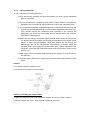
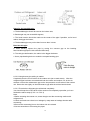
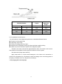
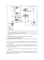
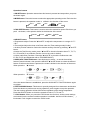
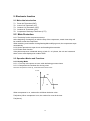
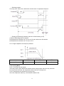
1
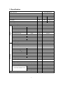
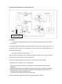
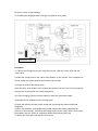
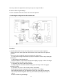
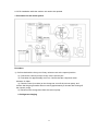
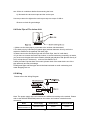
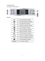
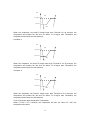
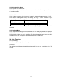
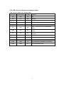
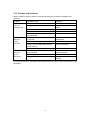
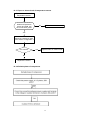
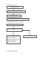
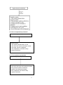
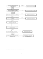
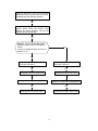
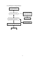
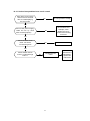
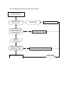
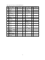
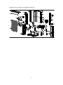
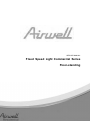
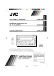
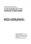
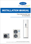
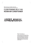
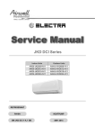
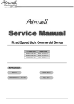
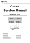
Fixed Speed Light Commercial Series
Floor-standing
SBF Indoor Units
Outdoor Units
AWSI-SBF048-N11
AWAU-YSF048-H13
REFRIGE
REFRIGERANT
R410A
SM SBF 1-A.1 GB
HEATPUMP
FEB, 2014
CONTENTS
1 .Safety Precautions ..................................................................................................................... 1
1.1 Precaution ................................................................................................................................... 1
1.2 Installation ................................................................................................................................... 1
1.3 Caution ........................................................................................................................................ 1
1.4 Operational.................................................................................................................................. 1
2. Specification ............................................................................................................................... 3
3.Dimension .................................................................................................................................... 4
3.1 Indoor Unit .................................................................................................................................. 4
3.2 Outdoor Unit ............................................................................................................................... 5
4.Refrigerant cycle diagram .......................................................................................................... 6
5 . Wiring diagram .......................................................................................................................... 7
6.Installation details..................................................................................................................... 9
6.1 Installation place ......................................................................................................................... 9
6.2 Installing ................................................................................................................................... 10
6.3 Refrigerant pipe connection ..................................................................................................... 12
6.4 Drain Pipe of The Indoor Unit ................................................................................................... 24
6.5 Wiring ....................................................................................................................................... 24
6.6 Test run ..................................................................................................................................... 25
7.External view and display ...................................................................................................... 26
7.1 External view ............................................................................................................................ 26
7.2 Control Panel ............................................................................................................................ 27
8.Operation characteristics ......................................................................................................... 29
9.Electronic function .................................................................................................................... 30
9.1 Main data Introduction .............................................................................................................. 30
9.2 Main Protection ......................................................................................................................... 30
9.3 Operation Modes and Functions............................................................................................... 30
9.4 Other Functions ........................................................................................................................ 35
10.Trouble shooting ..................................................................................................................... 36
10.1 Self-diagnosis ......................................................................................................................... 36
10.2 LEDs for the indication of outdoor trouble .............................................................................. 37
10.3Troubles and Solutions ............................................................................................................ 38
11.Exploded View and Spare Part list ........................................................................................ 49
1. Safety Precautions
1.1 Precaution
To prevent injury to the user or other people and property damage, the following instructions must
be followed.
Incorrect operation due to ignoring instruction will cause harm or damage.
Before service unit, be sure to read this service manual at first.
1.2 Installation
For electrical work, contact the dealer, seller, a qualified electrician, or an Authorized service
center.
Do not disassemble or repair the product by yourself.
Sharp edges could cause injury, be especially careful of the case edges and the fins on the
condenser and evaporator.
Be sure the installation area does not deteriorate with age.
Take care to ensure that power cable could not be pulled out or damaged during operation.
Do not place anything on the power cable.
Do not plug or unplug the power supply plug during operation.
Do not store or use flammable gas or combustible near the product.
When flammable gas leaks, turn off the gas and open a window for ventilation before turn the
product on.
If strange sounds, or small or smoke comes from product. Turn the breaker off or disconnect the
power supply cable as soon as possible.
When the product is soaked (flooded or submerged), contact an Authorized service center.
Be caution that water could not enter the product.
Turn the main power off when cleaning or maintaining the product.
When the product is not be used for a long time, disconnect the power supply plug or turn off the
breaker.
1.3 Caution
Always check for gas (refrigerant) leakage after installation or repair of product.
Install the drain hose to ensure that water is drained away properly.
Keep level even when installing the product.
Do not install the product where the noise or hot air from the outdoor unit could damage the
neighborhoods.
Use two or more people to lift and transport the product.
Do not install the product where it will be exposed to sea wind (salt spray) directly.
1.4 Operational
Do not expose the skin directly to cool air for long periods of time. (Do not sit in the draft).
Do not use the product for special purposes, such as preserving foods, works of art, etc. It is a
consumer air conditioner, not a precision refrigerant system.
Do not block the inlet or outlet of air flow.
Use a soft cloth to clean. Do not use harsh detergents, solvents, etc.
Do not touch the metal parts of the product when removing the air filter. They are very sharp.
1
Do not step on pr put anything on the product. (outdoor units)
Always insert the filter securely. Clean the filter every two weeks or more often if necessary.
Do not insert hands or other object through air inlet or outlet while the product is operated.
Do not drink the water drained from the product.
Use a firm stool or ladder when cleaning or maintaining the product.
Replace the all batteries in the remote control with new ones of the same type. Do not mix old and
mew batteries or different types of batteries.
Do not recharge or disassemble the batteries. Do not dispose of batteries in a fire.
If the liquid from the batteries gets onto your skin or clothes, wash it well with clean water. Do not
use the remote of the batteries have leaked.
2
2. Specification
Model Indoor Unit
AWSI-SBF048-N11
Model Outdoor Unit
AWAU-YSF048-H13
Installation Method of Pipe
Flared
Characteristics
Units
Cooling
Heating
Rated Capacity
kW
12,4
13,6(+3,5)
Input power
kW
4,62
4,84(+3,5)
W/W
2,68 / D
2,81 / D
EER/Energy Label
Power supply
Circuit breaker rating
V/Ph/Hz
380-415V~ 50Hz, 3Ph
A
25
Fan type & quantity
Centrifugal fan x1
Fan speeds
Air flow
(3)
INDOOR
External static pressure
Sound power level
(4)
Sound pressure level
(5)
H/M/L
RPM
580/500/400
H/M/L
m3/hr
1850/-/1500
Min-Max
Pa
/
H/M/L
dB(A)
66
H/M/L
dB(A)
56/-/48
l/hr
4,6
WxHxD
mm
550x1800x350
kg
48
WxHxD
mm
685x1910x540
kg
63.3
units
6
Moisture removal
Dimensions
Weight
Package dimensions
Packaged weight
Stacking height
Refrigerant control
Capillary
Compressor type. model
Scroll
Fan type & quantity
Axial x 2
Fan speeds
H/L
RPM
142/127
Air flow
H/L
m3/hr
5600
H/L
dB(A)
71
H/L
dB(A)
61
WxHxD
mm
938x1369x392
kg
111
mm
1095x1505x495
kg
123.4
units
2
Sound power level
(4)
Sound pressure level
(5)
OUTDOOR
Dimensions
Weight
Package dimensions
WxHxD
Packaged weight
Stacking height
Refrigerant type
R410A
Refrigerant charge (standard connecting tubing length)
kg(5m)
3.3
Additional charge per 1 meter
gr / 1m
60
Liquid line
In.(mm)
1/2"(Φ12.7)
Suction line
In.(mm)
3/4"(Φ19)
Max.tubing length
m.
50
Max.height difference
m.
25
Connections between units
Operation control type
Remote control
3
3. Dimension
3.1 Indoor Unit
Dimension
Mode
AWSI-SBF048-N11
W(mm)
D(mm)
H(mm)
550
350
1800
4
3.2 Outdoor Unit
Dimension
Mode
AWAU-YSF048-H13
W(mm)
D(mm)
H(mm)
W1(mm)
A(mm)
B(mm)
938
392
1369
1023
633.5
404
5
4. Refrigerant cycle diagram
INDOOR
OUTDOOR
CHECK VALVE
(Heating Model only)
LIQUID SIDE
2-WAY VALVE
T3 Condenser
temp. sensor
CAPILIARY TUBE
HEAT
EXCHANGE
(EVAPORATOR)
T1 Room temp.
sensor
HEAT
EXCHANGE
(CONDENSER)
T4 Ambient
temp. sensor
T2 Evaporator
temp. sensor
GAS SIDE
4-WAY VALVE
3-WAY VALVE
Accumulator
Compressor
High pressure switch
T5 Discharge temp. sensor
Low pressure
switch
COOLING
HEATING
6
5. Wiring diagram
AWSI-SBF048-N11
7
AWAU-YSF048-H13
8
6. Installation details
6.1 Installation place
6.1.1 Indoor Unit
a. A place which provides the spaces around the indoor unit as required above in the
diagram.
b. A place where is no obstacle near the inlet and outlet area.
c. A place which can bear the weight of the indoor unit.
d. A place which allows the air filter to be removed downward.
e. A place where the reception range is not exposed to direct sunlight.
f. In the center of the room where possible.
6.1.1.1 Please stand the unit in hard and flat ground;
Please reserve space for installation and maintenance.
6.1.2 Outdoor Unit
6.1.2.1 Before installing the outdoor unit, you should:
a). Select a place where no direct sunlight or other heat-radioactivity may reach. A
sunshade is needed if it is unavoidable.
b). Select a place that is easy to connect indoor unit's pipe and electric wires.
c). Avoid a place where combustible gas may leak or stay.
d). Keep it in mind that water may drain out of the outdoor unit while in "Heat" mode.
Caution:
Installation in the following places may cause trouble. If it is unavoidable to use in such
places, please consult with the dealer.
a. A place full of machine oil.
b. A saline place such as coast.
c. Hot-spring resort.
d. A place full of sulfide gas.
e. A place where there are high frequency machines such as wireless installation, welding
machine, medical facility.
f. A place of special environmental conditions.
6.1.2.2 If the outdoor unit is to be installed on a roof or where no constructions are around,
you should avoid hard wind blows directly to the air outlet, because it may
cause trouble for air-flow shortage.
9
6.1.2.3 Reserve enough space for installation, maintenance and unit-functioning.
Remove as many obstacles as possible nearby.
6.2 Installing
6.2.1 Indoor Unit:
1. Anti-falling;
To prevent the indoor unit from falling, you must:
a. Pay full attention to the unit because its long outer shape makes it easy to fall;
b. Firmly fix the unit to the wall or in the ground to avoid accidental falling.
2. Dismounting the lower front panel
Please take off the lower front panel before connecting the pipes/wires.
Pull down the two knobs on the grille, take off the two screws, then the air-inlet grille
10
goes free.
3. Take the Pipe Clip off before connecting the pipes and wiring; fit it when these finished.
Use accessories to connect the pipes/wires on both sides and back side.
6.2.2 Outdoor Unit:
1. Ship the a/c to the installation place originally packed;
2. Be careful while hanging the unit because the center of gravity of the unit is not
centralized;
3. Do not make the angle of inclination more than 45 degrees while shipping;(Avoid
horizontal storage)
4. Be sure the electric insulation work is well done if installed on metal ceiling / wall.
11
5. Fix the unit feet with bolts (M10/M8). Be sure the unit is fixed strongly enough to
against blast or earthquake.
6. Make a concrete basement to the unit by the following references.
For the value of A and B, please refer to the dimension part.
6.3 Refrigerant pipe connection
6.3.1
Pipe length and the elevation
The correct refrigerant quantity filled in the 5-meter-long pipe of the outdoor unit is marked
on the Product Data Plate. If you have to use longer pipe for every meter plus pipe, the
refrigerant should be added according to the following calculation.
Pipe size
Model
Gas
AWSI-SBF
048-N11
3/4’’ (Ф19)
Standard
Max.
Max.
Additional
length
Elevation
Length
refrigerant
(m)
B (m)
A (m)
(g/m)
5
10
20
60
Liquid
1/2’’
(Ф12.7)
Caution:
Capacity is base on standard length and maximum allowance length is base of reliability.
Oil trap should be installed per 5-7 meters.
12
6.3.2
Piping connection
6.3.2.1 Connecting Of Refrigerant Pipe
a) Only the correctly installing of indoor and outdoor unit done, can the refrigerant
pipe be connected.
b) The cut-off valves are completely close before ex-work. Before connecting the
refrigerant pipe, be careful to check whether the valves are completely close.
c) The connecting procedure of refrigerant pipe: first, unscrew the two valves on the
outdoor unit and the pipe-jointing nut on the indoor unit(please keep them carefully). Please connect the refrigerant pipe according to the manual, the
pipe-jointing nut should be screw tightly and no leakage. Note: you need two
wrenches to make balance.
d) When the connecting of refrigerant pipe is finished, before power on the system,
you should vacuum the indoor unit through the maintenance port on the cut-off
valves, or open the high-pressure valve, and exhaust the air through the
maintenance port on the low-pressure valve(closed). It will take about ten
seconds. Then screw tightly the maintenance port. (When supplement the
refrigerant, fill through the maintenance port of the low-pressure valves on the
outdoor unit ).
e) Open all the valves completely before power on the system, or it will be sick for
low efficiency.
f) Gas leak check. Make sure no gas from connections with leak detector or soap
water.
Caution:
A: Lo packed valve B: Hi packed valve
C and D are ends of indoor unit connection.
Caution in Handling the Packed Valve
a. Open the valve stem until it hits against the stopper. Do not try to open it further.
b. Securely tighten the valve stem cap with a spanner or the link.
13
Notes for the bendable pipe
a. The bendable pipe should be used on the indoor side;
b. Bend angel may not exceed 90 degrees;
c. The bend location should be made on the center of the pipe if possible, as for bend
radius, the bigger the better;
d. The bendable pipe may not be bent for more than 3 times.
Bend the thin pipe
a. While bending, expose the pipe by cutting the concave gap on the bending
heat-insulation pipe(roll it with soft band after bent).
b. To avoid pipe deformation, the radius is the bigger the better.
c. Use a pipe-bending device to make the compact bending pipe.
6.3.2.2 Using bronze pipe selling in market
Completely shut the cut-off valves of the outdoor unit (as ex-work status). After the
refrigerant pipe has been connected with both the indoor and outdoor unit, let the air
exhaust out from the maintenance gap on the low-pressure cut-off valves of the outdoor
unit. Screw the nuts tightly on the maintenance gap after the air has been drained.
6.3.2.3 To make the refrigerant pipe unblocked completely
You should keep the cut-off valves of the outdoor unit completely open after you have
finished the above steps (5.3.2.1 or 5.3.2.2)
Note:
1.Before screwing the reamer nut, smear the pipe and the connecting surface with
refrigerant oil;
2.Check and make sure there is no leakage by soap-water or leakage-checker after
connecting;
3.Be sure the connecting joint on the indoor side is insulated.
4.Use two wrenches to connecting the pipes.
14
Outside diameter
Torque
Additional
tightening
torque
mm
inch
N.cm
N.cm
Ф9.52
3/8
3270
3990
Ф12.7
1/2
4950
6030
Ф16
Ф19
5/8
3/4
6180
9720
7750
11860
6.3.3 Installation for the first time
Air and moisture in the refrigerant system have undesirable effects as below:
●
●
●
●
●
Pressure in the system rises.
Operating current rises.
Cooling or heating efficiency drops.
Moisture in the refrigerant circuit may freeze and block capillary tubing.
Water may lead to corrosion of parts in the refrigerant system.
Therefore, the indoor units and the pipes between indoor and outdoor units must be
leak tested and evacuated to remove gas and moisture from the system.
Gas leak check (Soap water method):
Apply soap water or a liquid neutral detergent on the indoor unit connections or
outdoor unit connections by a soft brush to check for leakage of the connecting points of
the piping. If bubbles come out, the pipes have leakage.
1. Air purging with vacuum pump
15
(Indoor unit)
(Outdoor unit)
(Liquid side)
Two-way valve
Close
(Gas side)
Three-way valve
Manifold valve
Compound meter
Pressure
gauge
-0.1MPa
Lo
Handle Lo
Charge hose
Close
Hi
Handle Hi
Charge hose
Vacuum
pump
Vacuum
pump
1) Completely tighten the flare nuts of the indoor and outdoor units, confirm that both the
2-way and 3-way valves are set to the closed position.
2) Connect the charge hose with the push pin of handle lo to the 3-way valves gas
service port..
3) Connect the charge hose of handle hi connection to the vacuum pump.
4) Fully open the handle Lo of the manifold valve.
5) Operate the vacuum pump to evacuate.
6) Make evacuation for 30 minutes and check whether the compound meter indicates -0.1Mpa.
If
the meter does not indicate -0.1Mpa after pumping 30 minutes, it should be pumped 20 minutes
more. If the pressure can’t achieve -0.1Mpa after pumping 50 minutes, please check if there are
some leakage points.
Fully close the handle Lo valve of the manifold valve and stop the operation of the vacuum
pump. Confirm that the gauge needle does not move (approximately 5 minutes after
turning off the vacuum pump).
7) Turn the flare nut of the 3-way valves about 45°counterclockwise for 6 or 7seconds
after the gas
coming out, then tighten the flare nut again. Make sure the pressure display in the
pressure indicator is a little higher than the atmosphere pressure. Then remove the
charge hose from the 3 way valve.
16
8) Fully open the 2 way valve and 3 way valve and securely tighten the cap of the 3 way
valve.
2. Air purging by refrigerant
Procedure:
1). Confirm that both the 2-way and 3-way valves are set to the closed position.
2). Connect the charge set and a charging cylinder to the service port of the 3-way
valve.
3). Air purging.
Open the valves on the charging cylinder and the charge set. Purge the air by
loosening the flare nut on the 2-way valve approximately 45’ for 3 seconds then closing
it for 1 minute; repeat 3 times.
After purging the air, use a torque wrench to tighten the flare nut on the 2-way valve.
4). Check the gas leakage.
Check the flare connections for gas leakage.
5). Discharge the refrigerant.
Close the valve on the charging cylinder and discharge the refrigerant by loosening
the flare nut on the 2-way valve approximately 45’ until the gauge indicates 0.3 to 0.5
Mpa.
6). Disconnect the charge set and the charging cylinder, and set the 2-way and 3-way
valves to the open position.
Be sure to use a hexagonal wrench to operate the valve stems.
7). Mount the valve stems nuts and the service port cap.
Be sure to use a torque wrench to tighten the service port cap to a torque 18N·m.
Be sure to check the gas leakage.
17
3. Adding the refrigerant if the pipe length >5m
Electronic scale
Procedure:
1). Connect the charge hose to the charging cylinder, open the 2-way valve and the
3-way valve.
Connect the charge hose which you disconnected from the vacuum pump to the valve at
the bottom of the cylinder. If the refrigerant is R410A, make the cylinder bottom up to
ensure the liquid charge.
2). Purge the air from the charge hose.
Open the valve at the bottom of the cylinder and press the check valve on the charge set
to purge the air (be careful of the liquid refrigerant).
3) Put the charging cylinder onto the electronic scale and record the weight.
4) Operate the air conditioner at the cooling mode.
5) Open the valves (Low side) on the charge set and charge the system with liquid
refrigerant.
6).When the electronic scale displays the proper weight (refer to the table), disconnect
the charge hose from the 3-way valve’s service port immediately and turn off the air
conditioner before disconnecting the hose.
7). Mount the valve stem caps and the service port
Use torque wrench to tighten the service port cap to a torque of 18N.m.
18
Be sure to check for gas leakage.
6.3.4 Adding the refrigerant after running the system for many years
Electronic scale
Procedure:
1). Connect the charge hose to the 3-way service port, open the 2-way valve and the
3-way valve.
Connect the charge hose to the valve at the bottom of the cylinder. If the refrigerant is
R410A, make the cylinder bottom up to ensure liquid charge.
2). Purge the air from the charge hose.
Open the valve at the bottom of the cylinder and press the check valve on the charge set
to purge the air (be careful of the liquid refrigerant).
3) Put the charging cylinder onto the electronic scale and record the weight.
4) Operate the air conditioner at the cooling mode.
5) Open the valves (Low side) on the charge set and charge the system with liquid
refrigerant.
6).When the electronic scale displays the proper weight (refer to the gauge and the
pressure of the low side), disconnect the charge hose from the 3-way valve’s service port
immediately and turn off the air conditioner before disconnecting the hose.
7). Mount the valve stem caps and the service port
19
Use torque wrench to tighten the service port cap to a torque of 18N.m.
Be sure to check for gas leakage.
6.3.5 Re-installation while the indoor unit need to be repaired
1. Collecting the refrigerant into the outdoor unit
Procedure
1). Confirm that both the 2-way and 3-way valves are set to the opened position
Remove the valve stem caps and confirm that the valve stems are in the opened
position.
Be sure to use a hexagonal wrench to operate the valve stems.
2). Connect the charge hose with the push pin of handle lo to the 3-way valves gas
service port.
3). Air purging of the charge hose.
Open the handle Lo valve of the manifold valve slightly to purge air from the charge
hose for 5 seconds and then close it quickly.
4). Set the 2-way valve to the close position.
5). Operate the air conditioner at the cooling cycle and stop it when the gauge
indicates 0.1MPa.
6). Set the 3-way valve to the closed position immediately
Do this quickly so that the gauge ends up indicating 0.3 to 0.5Mpa.
Disconnect the charge set, and tighten the 2-way and 3-way valve’s stem nuts.
Use a torque wrench to tighten the 3-way valves service port cap to a torque of
18N.m.
Be sure to check for gas leakage.
20
2. Air purging by the refrigerant
Procedure:
1). Confirm that both the 2-way and 3-way valves are set to the closed position.
2). Connect the charge set and a charging cylinder to the service port of the 3-way
valve
Leave the valve on the charging cylinder closed.
3). Air purging.
Open the valves on the charging cylinder and the charge set. Purge the air by
loosening the flare nut on the 2-way valve approximately 45’ for 3 seconds then closing
it for 1 minute; repeat 3 times.
After purging the air, use a torque wrench to tighten the flare nut on the 2-way valve.
4). Check the gas leakage
Check the flare connections for gas leakage.
5). Discharge the refrigerant.
Close the valve on the charging cylinder and discharge the refrigerant by loosening
the flare nut on the 2-way valve approximately 45’ until the gauge indicates 0.3 to 0.5
Mpa.
6). Disconnect the charge set and the charging cylinder, and set the 2-way and 3-way
valves to the open position
Be sure to use a hexagonal wrench to operate the valve stems.
7). Mount the valve stems nuts and the service port cap
Be sure to use a torque wrench to tighten the service port cap to a torque 18N.m.
Be sure to check the gas leakage.
21
6.3.6 Re-installation while the outdoor unit need to be repaired
1. Evacuation for the whole system
Procedure:
1). Confirm that both the 2-way and 3-way valves are set to the opened position.
2). Connect the vacuum pump to 3-way valve’s service port.
3). Evacuation for approximately one hour. Confirm that the compound meter
indicates -0.1Mpa.
4). Close the valve (Low side) on the charge set, turn off the vacuum pump, and
confirm that the gauge needle does not move (approximately 5 minutes after turning off
the vacuum pump).
5). Disconnect the charge hose from the vacuum pump.
2. Refrigerant charging
22
Electronic scale
Procedure:
1). Connect the charge hose to the charging cylinder, open the 2-way valve and the
3-way valve
Connect the charge hose which you disconnected from the vacuum pump to the valve at
the bottom of the cylinder. If the refrigerant is R410A, make the cylinder bottom up to
ensure liquid charge.
2). Purge the air from the charge hose
Open the valve at the bottom of the cylinder and press the check valve on the charge set
to purge the air (be careful of the liquid refrigerant).
3) Put the charging cylinder onto the electronic scale and record the weight.
4). Open the valves (Low side) on the charge set and charge the system with liquid
refrigerant
If the system cannot be charge with the specified amount of refrigerant, or can be
charged with a little at a time (approximately 150g each time) , operating the air
conditioner in the cooling cycle; however, one time is not sufficient, wait approximately 1
minute and then repeat the procedure.
5).When the electronic scale displays the proper weight, disconnect the charge hose
from the 3-way valve’s service port immediately
If the system has been charged with liquid refrigerant while operating the air conditioner,
23
turn off the air conditioner before disconnecting the hose.
6). Mounted the valve stem caps and the service port
Use torque wrench to tighten the service port cap to a torque of 18N.m.
Be sure to check for gas leakage
6.4 Drain Pipe of The Indoor Unit
1. Make sure the drain pipe is connected to the outdoor side downward;
2.The hard polyvinyl chloride(PVC)plastic pipe (external diameter 26 mm) sold is the
market is suitable for the attached soft drain pipe;
3.Please connect the Soft Drain Pipe with the Drain Pipe, then fix it with band;
4.If you have to connect the Drain Pipe indoors, to avoid condensing caused by air intake,
you must cover the pipe with heat-insulation material (polyethylene with Specific Gravity of
0.03, at least 9 mm in thickness), and use Glue Band to fix it.
5.After the Drain Pipe has been connected, please check if the water drains out of the
pipe efficiently and has no leakage.
6.Refrigerant pipe and Drainpipe should be heat-insulated to avoid condensing and
water-dropping later on.
6.5 Wiring
Please refer to the Wiring Diagram.
Note: The power supply of the air conditioner is different according to the models. Please
refer to the WIRING DIAGRAM pasted on the indoor and outdoor units before wire
connection.
Model
AWSI-SBF048-N11
AWAU-YSF048-H13
Power supply
Input Rated Amp
(Switch/Fuse)
Power Cord Size
380-420V~ 50Hz
32/25A
≥2.5mm
24
2
NOTE: The cable size and the current of the fuse or switch are determined by the
maximum current indicated on the nameplate which located on the side panel of the unit.
Please refer to the
nameplate before selecting the cable, fuse and switch.
6.6 Test run
Perform test operation after completing gas leak and electrical safety check. The test
operation time should last more than 30 minutes.
1. Open the panel and lift the panel up to angle which remains fixed. Do not lift the panel
any further when it stops with a "click" sound.
2. Press the manual switch button twice until the operation indicator lights, the unit will
operate on manual cool mode.
3. Check if all the functions works well while testing the air conditioner. Especially check
whether the drainage of indoor unit is smooth or not.
4. Press the manual switch button again till the operation indicator turns dark after
finishing the test operation and the unit stops operation.
25
7. External view and display
7.1 External view
This unit consists of indoor unit and outdoor unit.
Note:
All the pictures in this manual are for explanation purpose only.
They may be slightly different from the air conditioner you purchased (depend on model).
The actual shape shall prevail.
26
7.2 Control Panel
Control Buttons and Functions
Indicators
27
Operation buttons
1.ON/OFFbutton: Operation starts when this button is pressed and stops when you press
the button again.
2.MODEbutton: Press this button to select the appropriate operating mode. Each time the
button is pressed, the operation mode is shifted in the direction of the arrow:
AUTO
COOL
DRY
HEAT
FAN
3.FAN SPEED button: This button is used to select the desired fan speed. Each time you
push the button, a fan speed is shifted in the direction of the arrow:
AUTO
LOW
MED
HIGH
4.ADJUST button:
a.Temperature adjust: Press the "▲"and"▼" to adjust the temperature in a range of 17℃
~30℃.
b.Timer adjust: Adjust the timer on/off time under the Timer setting mode(0~24hs).
c.Auxiliary function selection: Select the desired auxiliary function by pressing "▲"and"▼"
button.
d.Under the Test Running mode, press "▲"and"▼"to check information about T1, T2, T3,
P4 , P5 and P9 (if no protection function occurs, the code is shifted).
e.Under malfunction condition: Press the "▲"and"▼" to check the malfunction code
E1,E2, E3 ,E6 and E9(details refer to TROUBLESHOOT).
5.AUXILIARY FUNCTION button: Use this button to select or cancel the auxiliary
feature.Press this button, then press the ADJUST"▲"and"▼"button to select the desired
feature. Each time the button is pressed, the mode is shifted in the direction of the arrow:
When press the "▲" button:
When press the "▼" button:
Once the desired feature is established, press the AUXILIARTY FUNCTION button again
to register .
6.TEST RUNNING button: This button is specially designed for maintenance technicians.
Press this button to perform test running operation, press it again to stop the operation.
The test running operation will last 30 minutes regardless of the setting temperature.
Press the ADJUST button to check the protective code of T1,T2 and T3.
7. LOCK button: When you press the LOCK button the first time, all the current settings
are locked in but the remote controller operation is available. And the LOCK indicator ( )
illuminates. Push it again to cancel the LOCK mode.
28
8. Operation characteristics
Mode
Temperature
Cooling
operation
Heating operation
Drying
operation
Room temperature
17℃~32℃
0℃~30℃
17℃~32℃
Outdoor temperature
-7℃~43℃
-7℃~24℃
18℃~ 43℃
CAUTION:
1. If air conditioner is used outside of the above conditions, certain safety protection
features may come into operation and cause the unit to function abnormally.
2. Room relative humidity less than 80%. If the air conditioner operates in excess of
this figure, the surface of the air conditioner may attract condensation. Please sets the
vertical air flow louver to its maximum angle (vertically to the floor), and set HIGH fan
mode.
3. Optimum performance will be achieved within this operating temperature.
29
9. Electronic function
9.1 Main data Introduction
T1:
T2:
T3:
T4:
T5:
Room Air Thermistor (RAT)
Indoor Coil Thermistor (ICT)
Outdoor Coil Thermistor (OCT)
Outdoor Air Thermistor (OAT)
Compressor Discharge Thermistor (CTT)
9.2 Main Protection
8.2.1 Time delay for the compressor start-up
At the beginning of energizing or after the stop of the compressor, certain time delay will
be needed to start the compressor.
When switching over between cooling/heating/dehumidifying mode, the compressor stops
automatically.
8.2.2 Sensor protection at open circuit and breaking disconnection.
8.2.3 Phase check function
If the phase sequence is detected wrong or lack of 1 or 2 phase, the unit won’t start and
there is error code displayed on outdoor PCB.
9.3 Operation Modes and Functions
9.3.1 Heating Mode
9.3.1.1 Four-way valve opens at once, while defrosting process closes.
9.3.1.2 Compressor and outdoor fan running rules:
Once the compressor starts up, it will follow the below rules:
T1-TS
Off
0
-1
On
When compressor is on, outdoor fan will follow the below rules::
Fan(below): When compressor is on, the outdoor fan runs all the time.
Fan(above):
30
T4
18
Off
16
On
9.3.1.3 Indoor fan running rules:
When the compressor is on, the indoor fan can be set to high/(med)/low/auto. And the
anti-cold wind function has the priority.
Auto fan action:
T1-Ts
Low
-2
-3
Medium
-4
-5
High
9.3.1.4 Defrost (only available to heating mode)
---Defrosting Conditions
Starting Of Defrosting Condition (meet one of the following is ok):
(1)Accumulated time when temperature of outdoor heat exchanger coil T3 is below 3°C
reaches to 40 minutes, then consecutive 3 minutes less than -5 degrees (Just for the
AC is turn on , whether or not the heating mode the temperature was detected, start
to statistical time when reach the temperature condition . Shut down or defrosting
calculate time again).
(2) Accumulated time when temperature of outdoor heat exchanger coil T3 is below 3°C
reaches to 60 minutes, then consecutive 3 minutes less than -4 degrees (Just for the
AC is turn on , whether or not the heating mode the temperature was detected, start
to statistical time when reach the temperature condition . Shut down or defrosting
calculate time again).
(3) Accumulated time when temperature of outdoor heat exchanger coil T3 is below 3°C
reaches to 80 minutes, then consecutive 3 minutes less than -2 degrees (Just for the
AC is turn on , whether or not the heating mode the temperature was detected, start
to statistical time when reach the temperature condition . Shut down or defrosting
calculate time again).
(4) Under evaporator high temperature protection, the accumulated time when outdoor
fan motor is off and compressor is on reaches up to over 90 minutes .( Shut down or
defrosting or T3 is over 15°C, calculate time again.)
31
--- Defrosting Action
Four-way valve, indoor fan, outdoor fan are shut down. Compressor keeps on.
--- Ending Of Defrosting Condition (meet one of the following is ok):
(1)Time of defrosting lasts 10 minutes.
(2) Temperature of outdoor coil T3 is up to 8°C and continues to 80 seconds.
(3) Temperature of outdoor coil T3 is up to 15°C.
9.3.1.5 High evaporator coil temp.T2 protection:
Model
TE7
TE8
TE9
AWSI-SBF048-N11
65
58
51
9.3.2 Cooling Mode
9.3.2.1 Four-way valve is closed.
If four-way valve is open before the machine enters cooling mode, then four-way valve will
be closed at the first time, the compressor starts under the cooling mode.
9.3.2.2 Compressor and outdoor fan running rules
Once the compressor starts up, it will follow the below rules:
32
T1-Ts
1
On
0
Off
When compressor is on, outdoor fan will follow the below rules::
Fan(below): When compressor is on, the outdoor fan runs all the time.
Fan(above):
T3
33
On
30
Off
9.3.2.3 Indoor fan running rules
In cooling mode, indoor fan runs all the time and the speed can be selected as high,
medium, low and auto.
The auto fan:
5.0
High
4.0
3.0
Medium
2.0
Low
9.3.2.4 Low evaporator coil temperature T2 protection
AC will enter T2 protection if any of the following conditions is satisfied.
Condition 1:
33
T2
On
T2CoolExit
T2CoolIn
Off
When the evaporator coil temp.T2 keeps lower than T2CoolIn for 30 minutes, the
compressor and outdoor fan will shut off. When T2 is higher than T2CoolExit, the
compressor and outdoor fan will restart up.
Condition 2:
T2
On
T2CoolExit
T2CoolIn-2
Off
When the evaporator coil temp.T2 keeps lower than T2CoolIn-2 for 20 minutes, the
compressor and outdoor fan will shut off. When T2 is higher than T2CoolExit, the
compressor and outdoor fan will restart up.
Condition 3:
T2
On
T2CoolExit
T2CoolIn-4
Off
When the evaporator coil temp.T2 keeps lower than T2CoolIn-4 for 8 minutes, the
compressor and outdoor fan will shut off. When T2 is higher than T2CoolExit, the
compressor and outdoor fan will restart up.
9.3.2.5 Condenser high temperature T3 protection
When T3≥62℃ for 3 seconds, the compressor will shut off. When T3<49℃,the
compressor will restart.
34
9.3.3 Dehumidifying Mode
9.3.3.1 Indoor fan speed is low.
9.3.3.2 Four-way valve is closed, the compressor and outdoor fan will operate the same
as in cooling mode.
9.3.4 Auto Mode
9.3.4.1. Under auto mode, the indoor fan is set to be auto and the temperature is 24°C.
9.3.4.2 When entering auto mode, the heating, fan only or cooling operation will be
automatically chosen according to the room temperature T1 and the set temperature Ts.
Condition
Mode
T1-Ts>1°C
Cooling
Fan
-1°C≤ T1-Ts≤1°C
T1-Ts<-1°C
Heating(fan for cooling only type)
9.3.4.3. If certain condition is met, then the corresponding protective function will be
executed.
9.3.5 Fan Only Mode
9.3.5.1 Temperature setting function is disabled, and no setting temperature is displayed.
9.3.5.2 Under this mode, four-way valve, compressor and outdoor fan are shut down.
9.3.5.3 High/Low/Auto fan can be switched over through manual control. Auto fan will be
controlled in line with cooling auto fan with temperature set to be 24°C.
9.4 Other Functions
9.4.1 LCD display
Mode, Set temp, fan speed, time, timer, protection etc.
9.4.2 Timer
The machine should be provided with max. Interval of 24h and min. resolution ratio of 30
minutes.
35
10.Trouble shooting
10.1 Self-diagnosis
Codes
P4
P5
P7
P9
P10
P11
P12
E1
E2
E3
E4
E5
E10
E13
E14
E15
EC
HS
Contents
Protection of temperature of indoor evaporator
Protection of temperature of outdoor condenser
Compressor discharge temperature protection
Protection of anti-cold wind
Low pressure protection
High pressure protection
Current overload protection
Open- or short-circuit of T1 temperature sensor
Open- or short-circuit of T2 temperature sensor
Open- or short-circuit of T3 temperature sensor
Open- or short-circuit of T4 temperature sensor
Communication malfunction between indoor unit and outdoor unit
Low pressure failure of compressor
Lack of phase
Default phase of compressor
Indoor fan speed is out of control
Refrigerant Leakage Detection
Defrosting
36
10.2 LEDs for the indication of outdoor trouble
Their codes are listed in the following table:
LED2(green)
LED3(yellow)
LED4(red) Contents
On
Off
Off
OK
Off
On
Off
Standby
Off
Off
Flash
Off
Flash
Off
Off
Flash
Flash
Off
Off
On
Flash
Off
Off
On
Off
On
Temperature protection of compressor
discharge
Flash
Flash
Off
High pressure protection
Flash
Off
Flash
Low pressure protection
Off
Flash
On
Overload of current
Flash
Flash
On
High temperature protection of condenser
Flash
Flash
Flash
Lack of phase
Phase sequence error
Indoor / outdoor units communication error
Open- or short-circuit of T3 temperature
sensor
Open- or short-circuit of T4 temperature
sensor
Fan jump selection error
37
10.3 Troubles and Solutions
Before calling for service, please review the following list of common problems and
solutions.
Problem
Possible Cause
Solutions
Air conditioner
Power failure
Wait for power restoring
does not
The power supply is disconnected.
Switch on the main power
operate at all
switch
The power fuse is blown.
Change the fuse
The timer is set.
Wait or cancel timer setting
The batteries of the remote control
Change the batteries.
are exhausted
Air conditioner
The temperature setting is too high
Set a more comfortable
does not
or too low.
temperature.
cool or
The air filter is clogged with dust
Clean the filter
heat well
The air inlet or outlet of the outdoor
Clear up the block
unit is blocked
Doors or windows are open
Close the doors or windows
Air conditioner
The air inlet or outlet of the outdoor
Clear up the block first, then
does not
unit is blocked
begin to operate.
cool or
Three-minute protection feature
Wait for a while
heat at all
Unappropriated temperature setting
Set the temperature
properly
If you still cannot solve the problem after trying the above, pull out the power plug and call
the dealer.
38
10.3.1 Open or short circuit of temperature sensor
Open or short circuit of
temperature sensor
Check the connections
between temperature
sensor and PCB. Are
the connections good?
No
Correct the connections.
Yes
Check the resistance value
of the sensor via Appendix 1
Is it normal?
Yes
Replace indoor or outdoor PCB.
No
Replace the sensor
10.3.2 Default phase of compressor
39
10.3.3 Phase sequence error
Phase sequence error
Change the order of the wires to power supply.
Switch on the unit again.
If the problem cannot be solved, the outdoor PCB is defective
10.3.4 High temperature protection of condenser
High temperature protection of condenser
Check the resistance of the temp. sensor
according to Appendix 1, is it normal?
No
Yes
Replace the sensor
Possible reason
1. Air or other gas in the refrigerant.
2. Heat exchanger is dirty
3. Outdoor fan or fan blade is defective
4. Outdoor unit is bad ventilation
5. Refrigerant is leakage
6. Outdoor PCB is defective
10.3.5 High pressure protection
40
10.3.6 Low temperature protection
Low temperature protection
Possible reason
1: The outdoor ambient temp. is low.
2: The wires are loose to the temp. sensor.
3: The temp. sensor is defective.
4: The evaporator or the filter is dirty.
5: System has block.
10.3.7 Low pressure protection
Low pressure protection
Possible reason
1: The wires are loose to the pressure switch.
2: The pressure switch is defective.
3: System has refrigerant leakage.
4: The evaporator or the filter is dirty.
10.3.8
Overload
of current
5: System
has block.
41
10.3.9 Indoor / outdoor unit communication error
42
Power off, then turn on the unit 5 seconds
later(reconnect the power wire).Is the error
still displaying after several minutes?
Yes
Check all the wirings between indoor and
outdoor, indoor PCB and outdoor PCB
following the wiring diagram. Are all the
wirings connected correctly?
Yes
Measure Vs, is it moving alternately
between positive value and negative
value?
(Vs is the voltage between S and N of
outdoor unit.)
No
Yes
Is the wiring to the outdoor PCB
connected correctly?
Is the wiring to the indoor PCB
connected correctly?
Yes
Yes
Change the outdoor main PCB.
Change the indoor main PCB.
Power on. Is the error extinguished?
Power on. Is the error extinguished?
No
No
Change the indoor main PCB.
Change the outdoor main PCB.
43
10.3.10 Refrigerant Leakage Detection
Shut off the power supply and
turn it on 5 seconds later. Is it
still displaying the error code?
Yes
Is there cool air blowing
out from indoor air outlet?
Check if T2 sensor is well
fixed. Correct the installation
or replace T2 sensor. Does
the problem remain again?
Yes
No
Yes
Is there any leakage? Especially
the connection parts, such as the
gas valve and the liquid valve.
No
Replace indoor PCB.
Yes
Repair the leakage and
recharge the refrigerant.
Is there any block i n g ? (Such as the
capillary or the welded points of the pipes.)
Yes
Clear the blocking.
44
10.3.11 Indoor fan speed has been out of control
Shut off the power supply
and turn it on 5 seconds
later. Is it still displaying
the error code?
No
The unit operates normally.
Yes
Shut off the power supply,
rotate the fan by hand.
Does it rotate properly?
No
Find out the cause and
have it solved. For
example, check
whether the fan is
blocked or the bearing
is broken?
No
Correct the connections.
Yes
Check the wires of fan
motor. Are all the
connections good?
Yes
Check whether the fan
motor is normal through
index 1?
No
Replace the fan
motor
45
If the
malfunction is
still existing,
replace the
main PCB
Index 1:
1 DC Fan Motor(control chip is in PCB)
1) Release the UVW connector. Measure the resistance of U-V, U-W, V-W. If the
resistance is not equal to each other, the fan motor must has problems and need to be
replaced.
46
10.3.12 Temperature protection of compressor discharge
Temperature protection of
compressor discharge
Check whether the
compressor discharge temp.
is more than 115°C ?
Check whether the
refrigerant is leak
Yes
Yes
Stop leaking and add refrigerant
No
Check whether the wiring
connection is right between
compressor discharge temp.
sensor and PCB according
to wiring diagrams?
No
Correct the wiring connection
Yes
Judge: The
discharge temp.
sensor is broken
Method: Check whether the
resistance of compressor
discharge temp. sensor is
right refer to the Appendix 2
No
Replace the compressor discharge temp. sensor
Yes
Replace outdoor main board
Trouble is solved
47
Appendix Temp. Sensor Resistance Value Table (℃--K)
℃
K Ohm
℃
℃
K Ohm
K Ohm
℃
K Ohm
-20
115.266
20
12.6431
60
2.35774
100
0.62973
-19
108.146
21
12.0561
61
2.27249
101
0.61148
-18
101.517
22
11.5000
62
2.19073
102
0.59386
-17
96.3423
23
10.9731
63
2.11241
103
0.57683
-16
89.5865
24
10.4736
64
2.03732
104
0.56038
-15
84.2190
25
10.000
65
1.96532
105
0.54448
-14
79.3110
26
9.55074
66
1.89627
106
0.52912
-13
74.5360
27
9.12445
67
1.83003
107
0.51426
-12
70.1698
28
8.71983
68
1.76647
108
0.49989
-11
66.0898
29
8.33566
69
1.70547
109
0.48600
-10
62.2756
30
7.97078
70
1.64691
110
0.47256
-9
58.7079
31
7.62411
71
1.59068
111
0.45957
-8
56.3694
32
7.29464
72
1.53668
112
0.44699
-7
52.2438
33
6.98142
73
1.48481
113
0.43482
-6
49.3161
34
6.68355
74
1.43498
114
0.42304
-5
46.5725
35
6.40021
75
1.38703
115
0.41164
-4
44.0000
36
6.13059
76
1.34105
116
0.40060
-3
41.5878
37
5.87359
77
1.29078
117
0.38991
-2
39.8239
38
5.62961
78
1.25423
118
0.37956
-1
37.1988
39
5.39689
79
1.21330
119
0.36954
0
35.2024
40
5.17519
80
1.17393
120
0.35982
1
33.3269
41
4.96392
81
1.13604
121
0.35042
2
31.5635
42
4.76253
82
1.09958
122
0.3413
3
29.9058
43
4.57050
83
1.06448
123
0.33246
4
28.3459
44
4.38736
84
1.03069
124
0.32390
5
26.8778
45
4.21263
85
0.99815
125
0.31559
6
25.4954
46
4.04589
86
0.96681
126
0.30754
7
24.1932
47
3.88673
87
0.93662
127
0.29974
8
22.5662
48
3.73476
88
0.90753
128
0.29216
9
21.8094
49
3.58962
89
0.87950
129
0.28482
10
20.7184
50
3.45097
90
0.85248
130
0.27770
11
19.6891
51
3.31847
91
0.82643
131
0.27078
12
18.7177
52
3.19183
92
0.80132
132
0.26408
13
17.8005
53
3.07075
93
0.77709
133
0.25757
14
16.9341
54
2.95896
94
0.75373
134
0.25125
15
16.1156
55
2.84421
95
0.73119
135
0.24512
16
15.3418
56
2.73823
96
0.70944
136
0.23916
17
14.6181
57
2.63682
97
0.68844
137
0.23338
18
13.9180
58
2.53973
98
0.66818
138
0.22776
19
13.2631
59
2.44677
99
0.64862
139
0.22231
48
11.Exploded View and Spare Part list
Exploded View of indoor unit: AWSI-SBF048-N11
49
Spare part list of indoor unit:AWSI-SBF048-N11
No.
1
Part Name
Air
inlet
assembly
grille
Qty
BOM Code
No.
Part Name
Qty
BOM Code
1
201143700277
15
Front guard board
for right side of
evaporator
1
201243700226
1.1
Air filter
1
P73001090755
16
Electric heater
1
202440300402
1.2
Air filter
1
P73001090752
17
Cover assembly
1
201243700181
2
Ambient
temperature
sensor assembly
1
202440120100
18
Display
assembly
box
1
203343390109
3
Ventilation ring
1
201141100002
18.1
Display
assembly
board
1
201343390111
4
Volute
shell
assembly
Fixing board for
volute shell
1
202243700191
19
1
201143700278
1
201240300410
19.1
1
202400100065
6
Centrifugal fan
1
201140500401
20
1
201240300654
7
Brushless
Motor
1
202400310114
21
1
2033437A0116
8
Chassis
1
201143700276
21.1
1
201343300060
9
Right side
assembly
cabinet
plate
of
1
201243700335
21.2
1
201343790046
10
Top
assembly
cover
1
201143700275
21.3
Inverter
control
board assembly
1
201319903024
Bottom
assembly
cabinet
Left side
plate
of
201243700007
21.4
Electronic
box
1
201243600009
1
201243700334
21.5
Reactor
1
202301000950
1
202301300111
21.6
Wire joint
1
202301450114
1
201543700140
22
Remote controller
1
203355091552
5
11
12
13
14
DC
plate
assembly
of
cabinet
Pipe temperature
sensor assembly
Evaporator
assembly
1
50
Air outlet assembly
Synchronous
motor
Cover of electronic
control box
Electronic control
box assembly
Auxiliary
heater
control board
Indoor
main
control
board
assembly
control
Exploded View of outdoor unit: AWAU-YSF048-H13
51
Spare part list of outdoor unit: AWAU-YSF048-H13
No.
Part Name
Qt
y
1
202440220061
22
BOM Code
No.
Part Name
Qt
y
1
201275690066
1
201248300242
1
201400710570
1
201675890952
1
202301820020
1
201601000041
1
201675790946
BOM Code
1
Ambient
temperature
sensor assembly
2
Rear net
1
201175690001
23
3
Condenser assembly
1
201575890169
24
3.1
Condenser
1
201575890170
25
3.1
Condenser
1
201575890171
25.1
3.2
Input pipe assembly
1
201675890900
25.2
3.3
Output pipe
1
201675890890
26
4
Pipe temperature sensor
assembly
1
202450200331
26.1
4-ways valve
1
201600600166
5
Big Handle assembly
1
201248100325
26.2
Gas valve
1
201600720425
6
Rear right clapboard
1
201248700199
27
Liquid
valve
assembly
1
201648790268
7
Handle
2
201148700009
27.1
Liquid valve
1
201600740519
8
Water collector
1
201148790000
28
Electronic
control
box
assembly
1
2033487A002
6
9
Front
assembly
1
201248700204
28.1
1
201248700286
10
Valve plate
1
201248790014
28.2
1
201348890015
11
Chassis
1
201248700285
28.3
Wire joint
1
202301450127
12
Partition
assembly
1
201275690068
28.3
Wire joint
4
202301450117
13
Accumulator cylinder
1
201601000636
28.4
Fan
motor
capacitor
2
202401100505
14
Fix clamp of segregator
1
201248700067
28.7
AC contactor
1
202300850045
15
Left supporter
1
201275690067
28.8
Transformer
1
202300900127
16
Air outlet grille
2
2011487A0002
28.9
1
201145000002
Round sticker for air
outlet grille
2
2011374A0005
1
201319901033
17
Front panel
1
201248700201
29
Copper nut
1
201600320002
18
Axial flow fan
2
201100300045
30
Crankcase
electric heater
1
202403101716
19
Fan motor
2
202400401375
31
Discharge
temperature
controller
1
202301610500
20
Supporter assembly of
fan motor
1
201248700197
32
Suction
pipe
assembly
1
2016758A017
0
21
Supporter of fan motor
holder
1
201248300232
32.1
Pressure
switch
1
202301800118
clapboard
board
52
Supporting bar
Top
cover
assembly
Compressor
Discharge pipe
assembly
Pressure
switch
Muffler
4-ways valve
assembly
Electronic
installing plate
Outdoor main
control board
assembly
Installation box
of electric parts
Low
ambinet
module
SERVICE MANUAL
Fixed Speed Light Commercial Series
Floor-standing
53