1
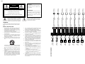
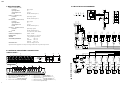
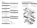
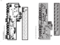
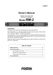
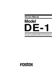
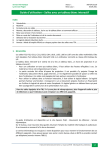
Service Manual
Model
DS-8
DIGITAL AUDIO SELECTOR
FOSTEX CORPORATION 3-2-35 Musashino, Akishima, Tokyo, Japan 196-0021
FOSTEX CORPORATION OF AMERICA 15431 Blackburn Ave., Norwalk, CA 90650, U.S.A.
© PRINTED IN JAPAN OCT. 1999 8288786000
DS-8
DS-8
CAUTION:
CAUTION
TO PREVENT ELECTRIC SHOCK, MATCH
RISK OF ELECTRIC SHOCK
DO NOT OPEN
WIDE BLADE OF PLUG TO WIDE SLOT,
OUTPUT 8
(OPTICAL)
OUTPUT 7
(OPTICAL)
OUTPUT 6
(OPTICAL)
OUTPUT 5
(OPTICAL)
OUTPUT 4
(OPTICAL)
POUR ÉVITER LES CHOCS ÉLECTRIQUES,
DO NOT REMOVE COVER (OR BACK).
OUTPUT 3
(OPTICAL)
ATTENTION:
CAUTION: TO REDUCE THE RISK OF ELECTRIC SHOCK,
OUTPUT 2
(COAXIAL)
OUTPUT 1
(COAXIAL)
FULLY INSERT.
INTRODUIRE LA LAME LA PLUS LARGE DE
NO USER-SERVICEABLE PARTS INSIDE.
LA FICHE DANS LA BORNE CORRESPONDANTE DE LA PRISE ET POUSSER
REFER SERVICING TO QUALIFIED SERVICE PERSONNEL.
INPUT SELECTOR
OUT 8
INPUT SELECTOR
OUT 7
INPUT SELECTOR
OUT 6
“TO REDUCE THE RISK OF FIRE OR ELECTRIC SHOCK,
DO NOT EXPOSE THIS APPLIANCE TO RAIN OR MOISTURE.”
INPUT SELECTOR
OUT 5
“WARNING”
INPUT SELECTOR
OUT 4
INPUT SELECTOR
OUT 1
The exclamation point within an equilateral
triangle is intended to alert the user to the
presence of important operating and maintenance (servicing) instructions in the literature
accompanying the appliance.
INPUT SELECTOR
OUT 3
The lightening flash with arrowhead symbol,
within an equilateral triangle, is intended to
alert the user to the presence of uninsulated
“dangerous voltage” within the product's enclosure that may be of sufficient magnitude to
constitute a risk of electric shock to persons.
INPUT SELECTOR
OUT 2
JUSQU' AU FOND.
15.
7.
8.
An appliance and cart combination should be moved with
care. Quick stops, excessive force, and uneven surfaces
may cause the appliance and cart combination to overturn.
Wall or Ceiling Mounting - The appliance should be
mounted to a wall or ceiling only as recommended by the
manufacturer.
Ventilation - The appliance should be situated so that its
location or position does not interfere with its proper ventilation. For example, the appliance should not be situated on a bed, sofa, rug, or similar surface that may block
the ventilation openings; or, placed in a built-in installation, such as a bookcase or cabinet that may impede the
flow of air through the ventilation openings.
16.
17.
INPUT 8
(OPTICAL)
14.
INPUT 7
(OPTICAL)
13.
INPUT 6
(OPTICAL)
6.
12.
INPUT 5
(OPTICAL)
5.
11.
INPUT 4
(OPTICAL)
4.
10.
Heat - The appliance should be situated away from heat
sources such as radiators, heat registers, stoves, or other
appliances (including amplifiers) that produce heat.
Power Sources - The appliance should be connected to a
power supply only of the type described in the operating
instructions or as marked on the appliance.
Grounding or Polarization - The precautions that should
be taken so that the grounding or polarization means of
an appliance is not defeated.
Power Cord Protection - Power supply cords should be
routed so that they are not likely to be walked on or
pinched by items placed upon or against them, paying
particular attention to cords at plugs, convenience receptacles, and the point where they exit from the appliance.
Cleaning - The appliance should be cleaned only as recommended by the manufacturer.
Nonuse Periods - The power cord of the appliance should
be unplugged from the outlet when left unused for a long
period of time.
Object and Liquid Entry - Care should be taken so that
objects do not fall and liquids are not spilled into the enclosure through openings.
Damage requiring Service - The appliance should be serviced by qualified service personnel when:
A. The power supply cord or the plug has been damaged;
or
B. Objects have fallen, or liquid has been spilled into the
appliance; or
C. The appliance has been exposed to rain; or
D. The appliance does not appear to operate normally or
exhibits a marked changed in performance; or
E. The appliance has been dropped, or the enclosure
damaged.
Servicing - The user should not attempt to service the appliance beyond that described in the operating instructions. All other servicing should be referred to qualified
service personnel.
INPUT 3
(OPTICAL)
3.
9.
INPUT 2
(COAXIAL)
2.
Read instructions - All the safety and operating instructions should be read before the appliance is operated.
Retain instructions - The safety and operating instructions
should be retained for future reference.
Heed warnings - All warnings on the appliance and in the
operating instructions should be adhered to.
Follow instructions - All operating and use instructions
should be followed.
Water and Moisture - The appliance should not be used
near water - for example, near a bathtub, washbowl,
kitchen sink, laundry tub, in a wet basement, or near a
swimming pool, and the like.
Carts and Stands - The appliance should be used only
with a cart or stand that is recommended by the manufacturer.
BLOCK DIAGRAM
1.
INPUT 1
(COAXIAL)
SAFETY INSTRUCTIONS
11
DS-8
OUT8
INPUT SEL
S18
SRBV18
DS-8
2
3
4
5
6
7
8
9
OUT7
INPUT SEL
S17
SRBV18
1
10
2
3
4
5
6
7
8
9
OUT5
INPUT SEL
S15
SRBV18
1
10
2
3
4
5
6
7
8
9
OUT4
INPUT SEL
S14
SRBV18
1
10
2
3
4
5
6
7
8
9
2
3
4
5
6
7
8
9
the Model DS-8.
1
10
OUT2
INPUT SEL
S12
SRBV18
* The following accessories are supplied with DS-8 as the standard accessories.
2
3
4
5
6
7
8
9
!
Owner's manual
: 8288449000 (for export model)
AC adaptor AD-12A
: 8288450000 (for domestic model)
: 8270727003 (for USA/CND)
: 8270727006 (for EUR)
: 8270727007 (for UK)
OUT1
INPUT SEL
: 8270727010 (for JPN)
* Following is the packing material for the Model DS-8.
1
10
S11
SRBV18
1
10
!
FPC-17P
17
16
15
14
13
12
11
10
9
8
7
6
5
4
3
2
1
Carton, inner, DS-8
: 8228734000
Packing side, DS-8
Packing, AC, DS-8
: 8228436000
: 8228437000
CAUTION
IN5
IN1
IN6
IN2
IN7
IN3
IN8
IN4
OUT8
OUT1
OUT7
OUT2
OUT6
OUT3
OUT5
OUT4
2
3
4
5
6
7
8
9
DGND
NOTES
* Parts List and circuit diagrams are given in this manual to assist the service technician in maintaining
OUT3
INPUT SEL
S13
SRBV18
1
10
J2
3. EXPLODED VIEW, PCB ASSEMBLY AND PARTS LIST . . . . . . 5
4. CIRCUIT & BLOCK DIAGRAMS . . . . . . . . . . . . . . . . . . . . . . . . 9
OUT6
INPUT SEL
S16
SRBV18
2
3
4
5
6
7
8
9
SW PCB
1. SPECIFICATIONS . . . . . . . . . . . . . . . . . . . . . . . . . . . . . . . . . . . . . . . 4
2. CONTROLS, INDICATORS AND CONNECTORS . . . . . . . . . . . . 4
1
10
10
TABLE OF CONTENTS
Parts marked with this sign are safety critical components. They must always be replaced with identical
components. Refer to the Fostex Parts List and ensure exact replacement.
3
1.
2.
3.
4.
4
7
9
6
5
4
3
8
2
1
7
7
6
6
S/P DIF OUTPUT
INPUT SELECTOR [INPUT SELECTOR 1 - 8]
Input connector 8 [S/P DIF INPUT 8]
Output connector 8 [S/P DIF OUTPUT 8]
Power switch / POWER LED [POWER]
5
4
5.
6.
7.
8.
9.
3
2
< REAR PANEL >
5
12V
DC IN
1
S/P DIF INPUT
Input connector 1, 2 [S/P DIF INPUT 1, 2]
Input connector 3 - 7 [S/P DIF INPUT 3 - 7]
Output connector 1, 2 [S/P DIF OUTPUT 1, 2]
Output connector 3 - 7 [S/P DIF OUTPUT 3 - 7]
DC IN connector [DC IN 12V]
D+5
D+5
D+5
D+5
D+5
C63
0.1
C53
0.1
C43
0.1
C33
0.1
C23
0.1
DGND
DGND
DGND
DGND
DGND
DGND
R67
jumper
DGND
R66
2.2K
DGND
R65
3.3K
D+5
R57
jumper
R56
2.2K
DGND
R55
3.3K
D+5
R47
jumper
R46
2.2K
DGND
R45
3.3K
D+5
R37
jumper
R36
2.2K
DGND
R35
3.3K
D+5
R27
jumper
R26
2.2K
DGND
R25
3.3K
D+5
R16
2.2K
12
2
12
10
8
6
4
R24
2.2K
DGND
C22
47P
J2
FPC-17P
DGND
13
U2F
74HC04
11
U2E
74HC04
9
U2D
74HC04
5
U2C
74HC04
3
U2B
74HC04
1
U2A
74HC04
U1F
74HCU04
13
R23 47K
DGND
R14
2.2K
< FRONT PANEL >
2
3
1
2
3
1
2
3
1
2
3
1
2
3
1
2
R17
jumper
2
C21 22P
U1A
74HCU04
1
2. CONTROLS, INDICATORS & CONNECTORS
INPUT8
(OPTICAL)
U61
GPIF37R1
INPUT7
(OPTICAL)
U51
GPIF37R1
INPUT6
(OPTICAL)
U41
GPIF37R1
INPUT5
(OPTICAL)
U31
GPIF37R1
INPUT4
(OPTICAL)
U21
GPIF37R1
INPUT3
(OPTICAL)
3
POWER
R15
3.3K
INPUT 8
C13
0.1
8
C12
47P
8
1
INPUT 7
S/P DIF DIGITAL AUDIO SELECTOR
U11
GPIF37R1
8
DGND
7
1
D+5
2
8
DGND
INPUT SELECTOR
D+5
INPUT 6
7
S/P DIF OUTPUT
D22
DIODE
INPUT 5
2
1
S/P DIF INPUT
R21
75
INPUT 4
7
8
5
6
DGND
1
OUTPUT 8
R22
10
2
8
4
3
D21
DIODE
7
1
5
6
D+5
2
OUTPUT 7
L21
jumper
INPUT 3
8
4
3
C25
33/25
INPUT 2
7
5
6
5
1
OUTPUT 6
DGND
2
8
4
3
DGND
7
1
5
6
4
2
OUTPUT 5
3
8
4
3
INPUT2
(COAXIAL)
7
1
5
6
4
D12
DIODE
2
OUTPUT 4
R11
75
7
8
4
3
R13 47K
U4C
U1D
74HCU04
8
9
U1C
74HCU04
6
5
U4B
U1E
74HCU04
10
11
U1B
74HCU04
4
3
U3D
74HC04
8
9
U3C
74HC04
6
5
U3B
74HC04
4
3
U3A
74HC04
2
1
C27
33/25
C17
33/25
U3F
74HC04
12
13
U3E
74HC04
10
11
Specifications and appearance are subject to change without notice for product improvement.
2
2
1
5
6
1
INPUT 1
OUTPUT 3
INPUT1
(COAXIAL)
4
3
3
2
1
3
2
1
DGND
C65
0.1
DGND
C55
0.1
DGND
C45
0.1
DGND
C35
0.1
DGND
C25
0.1
DGND
C15
0.1
DGND
L22
jumper
DGND
L12
jumper
4
6
4
6
D+5
D+5
D+5
D+5
D+5
D+5
3
1
2
3
1
2
3
1
2
3
1
2
3
1
2
3
1
2
TRANSFORMER
T21
TRANSFORMER
T11
R28
75
R18
75
OUTPUT8
(OPTICAL)
U62
GPIF38T2
OUTPUT7
(OPTICAL)
U52
GPIF38T2
OUTPUT6
(OPTICAL)
U42
GPIF38T2
OUTPUT5
(OPTICAL)
U32
GPIF38T2
OUTPUT4
(OPTICAL)
U22
GPIF38T2
OUTPUT3
(OPTICAL)
U12
GPIF38T2
L24 BEAD
L23
BEAD
L14 BEAD
L13
BEAD
J1
YKB31-0012
DGND
C14
0.1
Square shape optical
S/P DIF (IEC60958 part 3)
12 V (Inner: Plus, Outer: Minus)
32 kHz ~ 96 kHz
44 (H) x 482 (W) x 113 (D) mm
1.4 kg (excluding accessories)
JPN
: 100 V AC
USA/CND : 120 V AC
UK/EUR
: 230 V AC
Fostex AC adaptor AD-12A
D11
DIODE
5
6
R12
10
OUTPUT 2
3
C15
33/25
4
3
2
C11 22P
1
L11
jumper
D+5
POWER SUPPLY
J11
YKC21-3079
5
6
2
3
1
C24
0.1
4
3
2
1
C4
10/16
DGND
9
1
13
11
D+5
U4A
2
12
10
U4E
U4F
8
U4D
IN
U91
C5
10/16
C6
0.1
C1
10/35
D2
LED
R1
470
J5
8283-3P
W1
B. IN-3P
3
G
2
C7
0.1
D+5
1
C8
0.1
DGND
OUT
78M05
C9
1
2
(NON)
J4
C92
0.1
PCB, REGULATOR
C91
0.1
D1
DIODE
DGND
C2
C3
100/10 10/16
DGND
D+5
L1
jumper W3
S1
OUTPUT2
(COAXIAL)
OUTPUT1
(COAXIAL)
L2
jumper W4
DGND
5
J12
YKC21-3079
RCA pin jack
75 Ω
0.5 Vp-p
S/P DIF (IEC60958 part 3)
IN5
IN1
IN6
IN2
IN7
IN3
IN8
IN4
OUT8
OUT1
OUT7
OUT2
OUT6
OUT3
OUT5
OUT4
OUTPUT 1
Square shape optical
S/P DIF (IEC60958 part 3)
3
2
1
4
3
RCA pin jack
75 Ω
0.5 Vp-p
S/P DIF (IEC60958 part 3)
17
16
15
14
13
12
11
10
9
8
7
6
5
4
3
2
1
INPUT 1, 2 (COAXIAL IN)
Connector
Input Impedance
Normal Input Level
Format
INPUT 3 - 8 (OPTICAL IN)
Connector
Format
OUTPUT 1, 2 (COAXIAL OUT)
Connector
Input Impedance
Normal Input Level
Format
OUTPUT 3 - 8 (OPTICAL OUT)
Connector
Format
DC IN
SAMPLING FREQUENCY
DIMENSIONS
WEIGHT
POWER REQUIREMENT
3
2
1
1. SPECIFICATIONS
MAIN / REGULATOR PCB
DS-8
DS-8
4. CIRCUIT & BLOCK DIAGRAMS
9
DS-8
DS-8
DS-8 Parts List
3. EXPLODED VIEW, PCB ASSEMBLY AND PARTS LIST
• MAIN PCB assy
Ref. No.
DS-8 OVERALL EXPLODED VIEW & PARTS LIST
Part No.
Description
8274 2430 00 PCB Assy, Main, DS-8
8251 9661 01 Plain PCB, Main, DS-8
Ref. No.
U001
U002, 003
U004
U011~061
U012~062
Part No.
8236 0074 01
8236 0812 00
8245 5530 10
8245 5520 10
Ref. No.
D001
D002
D011, 021
D012, 022
Part No.
8234 0196
8234 0201
8234 5007
8234 5007
02
00
00
00
ICs
Description
DIP, DG, CMOS, 74HCU04
DIP, DG, CMOS, 74HC04
N/A
Connector, opt, GPIF37R1
Connector, opt, GPIF38T2
DIODEs
Description
HT, DSK10C-BT
Opt, V, LED, green, GLK3KG8
HT, 1SS136
HT, 1SS136
Ref. No.
J002
J004
J005
J011, 012
L001, 002
L011, 021
L012, 022
L013, 023
L014, 024
S001
T011, 021
W003, 004
W401
Ref. No.
R001
R011, 021
R012, 022
R013, 023
R014, 024
R015~065
R016~066
R017~067
R018, 028
8
Part No.
8230 1384
8230 1387
8230 1381
8230 1384
8230 1382
8230 1383
8230 1382
8230 1387
Ref. No.
C001
C002
C003~005
C006, 007
C008, 009
C011, 021
C012, 022
C013~063
C014, 024
C015~065
C016, 026
C017, 027
CAPACITORs
ALU = Electrolytic type
CER = Ceramic type
Part No.
Description
8232 1451 06 VT, ALU, 35V, 10µF, 20%, SME-VB
8232 1421 07 VT, ALU, 10V, 100µF, 20 %, SME-VB
8232 1431 06 VT, ALU, 16V, 10µF, 20 %, SME-VB
8232 8181 04 VT, CER, 25V, 0.1µF, +80-20%, YF
N/A
8232 8012 20 VT, CER, 50V, 22pF, 5%, SL
8232 8014 70 VT, CER, 50V, 47pF, 5%, SL
8232 8181 04 VT, CER, 25V, 0.1µF, +80-20%, YF
8232 8181 04 VT, CER, 25V, 0.1µF, +80-20%, YF
8232 8181 04 VT, CER, 25V, 0.1µF, +80-20%, YF
8232 1443 36 VT, ALU, 25V, 33µF, 20 %, SME-VB
8232 1443 36 VT, ALU, 25V, 33µF, 20 %, SME-VB
Ref. No.
Y201
E201
E202
J001
MISCELLANEOUS
Part No.
Description
8276 8730 02 Tube, UL, black, 1, L05
Jumper, F5
Jumper, F10
8245 5410 00 Connector, jack, DC inlet, YKB31-0012
Ref. No.
Part No.
1
8221 2230 00
Ref. No.
Description
Cover, DS-8/DP-8
10
2
3
8221 3090 00
8221 3100 00
Panel, dress, DS-8
Panel, rear, DS-8
4
5
8274 2450 00
8274 2440 00
PCB assy, SW, DS-8
PCB assy, Regulator, DS-8
6
7
8274 2430 00
8226 0130 02
PCB assy, MAIN, DS-8
Button, push, B, N08
8
9
8221 2220 00
8226 1870 02
Chassis, DS-8/DP-8
Knob, VR, W, N19
Part No.
Description
8270 7270 03
8270 7270 06
AC adaptor, AD-12A, 120V, USA/CND
AC adaptor, AD-12A, 230V, EUR
8270 7270 07
8270 7270 10
AC adaptor, AD-12A, 240V, UK
AC adaptor, AD-12A, 100V, JPN
11
12
8226 0191 00
8216 6570 00
Escutcheon, B
Spacer, escutcheon
13
8276 8396 05
Cable, flat, FFC, 17P, L50
(Included in MAIN PCB assy.)
14
8216 6920 00
Sheet, volume, DS-8/DP-8
• REGULATOR PCB assy
Ref. No.
RESISTORs
Description
71 HT, Carbon, 1/4W, 470Ω, 5%
50 HT, Carbon, 1/4W, 75Ω, 5%
00 HT, Carbon, 1/4W, 10Ω, 5%
73 HT, Carbon, 1/4W, 47kΩ, 5%
22 HT, Carbon, 1/4W, 2.2kΩ, 5%
32 HT, Carbon, 1/4W, 3.3kΩ, 5%
22 HT, Carbon, 1/4W, 2.2kΩ, 5%
Jumper, F5
50 HT, Carbon, 1/4W, 75Ω, 5%
Part No.
Description
8245 2720 17 Connector, PI, jack, FPC, 17P
N/A
8245 1711 03 Connector, PI, jack, 8283, 3P, WHT
8245 3130 01 Connector, PL, jack, RCA, 2P, BLK, WS
N/A
N/A
N/A
8242 1860 13 Filter, T, EMI, LFW7B-M3R2T
8242 1860 13 Filter, T, EMI, LFW7B-M3R2T
8253 4610 01 Switch, P, push, power, SDDL
8242 2350 00 Transformer, digital out, K7-T
Jumper, F5
8276 8396 05 Cable, flat, FFC, 17P, L50
1
Part No.
Description
8274 2440 00 PCB Assy, Regulator, DS-8
8251 9660 02 Plain PCB, Regulator, DS-8
BBT 3x8
BZn
11
10
Ref. No.
Part No.
Description
U091
8236 0320 01 IC, 220, AN, regulator, NJM78M05FA
C091, 092 8232 8181 04 Capacitor, VT, CER, 25V, 0.1µF,
+80-20%, YF
W001
8276 7730 10 Cable assy, 3P, WHTMT/F-MT/BS, L100
E101, 102
N/A
2
BBT 3x6 BZn
12
BBT 3x8 BZn
3
BBT 3x8 BZn
Ref. No.
Part No.
8274 2450 00
8251 9660 03
BBT 3x6 BZn
4
• SW PCB assys
13
Description
PCB Assy, SW, DS-8
Plain PCB, SW, DS-8
Ref. No.
Part No.
Description
S011~081 8253 4600 01 SW, P, rotary, 1-8, non-shortening, SRBV18
J003
8245 2721 17 Connector, PL, jack, FPC, 17P
W002
N/A
E101, 102
N/A
Abbreviation
DIP: Dual In Line
H:
Horizontal mount
V:
Vertical mount
T:
Taping device
PI: Penetrate mount I form (straight)
PL: Penetrate mount L form (right angle)
DG: Digital
5
BBT 3x6 BZn
BBT 3x6
BZn
P 3x5 CZn
14
9
6
Attached to each pot.
8
P 3x5 CZn
7
5
S11
6
S21
10
R35
S31
6
1
10
C33
R17
IN4
R37
5
5
C23
J1
P
IN5
R26
D2
W3
C16
L1
W4
6
6
L24
1
3
C63
C2
R65
R66
C4
R67
C8
R1
10
R28
10
L23
S71
6
W1
1
S81
C91
10
3
S61
6
8
T11
1 2 3
IN7
S51
R56
10
U1
C6
1
6
6
R45
S41
10
J2
1
U22 OUT4
IN5
C65
1 2 3
U31
IN6
1
10
R47
S71
1 2 3
U41
5
R14
C12
C11
R13
C3
W2
C27
IN8
1
U91
C92
U61
L22
OUT8
R18
U62
L13
3 2 1
1
U51
C53
3 2 1
T21
3
OUT1 J12
2
L24
R57
C65
1
C15
R56
OUT2
4
10
R55
J3
1
U4
OUT3
1 2 3
U12
S61
C4
R24
C22
C21
R23
S1
U3
8
C25
C35
OUT4
10
6
1
R67
C43
POWER SW
8
U22
C45
OUT5
1 2 3
U32
1 2 3
OUT6
1 2 3
U42
S51
5
U62
C33
C1
D1
C55
OUT7
1 2 3
U52
10
6
1
REGULATOR,DP-8
U61
R35
6
5
C8
1
8
S31
IN4
C23
10
17
6
IN3
S21
8
10
U2
3
IN2
4
D2
C1
D1
J3
1
C55
003
1 2 3
U11
8251966
SW,DP-8
W2
1 2 3
U21
S81
6
17
8251966 001
MAIN,DP-8
R26
17
B
S41
5
L14
8251966 002
1
8
U32 OUT5
R25
5
S
IN6
6
1
C3
IN3
R27
6
1
C53
IN2
10
C13
5
J2
1
R28
IN1
D12
J4
R45
R46
R24
C43
C22
C21
R23
L21
D21
R21
1
R36
1
R57
C24
D2
R2
1
1
R47
• Foil Side of MAIN / REGULATOR / SW PCB assys
10
R22
5
R25
17
C9
IN7
C14
8
L12
D22
R11 L11
C7
D11
R12
1
2
1
C26
1
R15
R16
U2
R55
C6
C45
1
6
R22
5
C5
C35
C26
J5
1
8
C25
U4
U12 OUT3
C15
U52 OUT7
D22
5
R14
C12
C11
R13
OUT1
U1
J12
J5
C69
L13
L22 R18
U91
1
3
C24
L23
1
3
T21
3
C92
W1
1
C91
C2
R66
R65
T11
C17
L14
1
U51
C27
C14
5
U41
R17
R15
R16
1
U31
R11
S11
10
1
IN1
2
J1 DC IN
D11 C16
5
U21
1
U11
OUT8
5
R46
J11
1
1
J11
L21
5
IN8
U42 OUT6
U3
R1
W3
L1
W4
L2
POWER SW
S1
R12
1
• Parts Side of MAIN / REGULATOR / SW PCB assys
L11
5
6
D12
C5
1
DS-8 PCB ASSEMBLIES
DS-8
DS-8
J4
2
C7
C13
R27
R37
R36
L12
C17
3
C9
L2
7