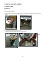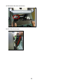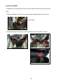
1
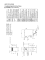
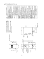
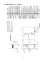
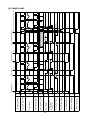
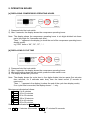
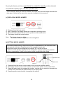
NO.
L009-872
ISSUED: JUN. 1, 2012
REVISED:
HOSHIZAKI
CUBELET ICE DISPENSER
DCM-60KE
DCM-60KE-P
DCM-120KE
DCM-120KE-P
MODEL
SERVICE MANUAL
CONTENTS
PAGE
I. SPECIFICATIONS -------------------------------------------------------------------------------------- 1
1. DIMENSIONS/SPECIFICATIONS ----------------------------------------------------------------- 1
[a] DCM-60KE (L013: Continental) ---------------------------------------------------------------- 1
[b] DCM-60KE (L013-C101: UK) ------------------------------------------------------------------- 2
[c] DCM-60KE (L013-C201: Oceania) ------------------------------------------------------------ 3
[d] DCM-60KE (L013-C301: China)---------------------------------------------------------------- 4
[e] DCM-60KE (L013-C130: Middle East)-------------------------------------------------------- 5
[f] DCM-60KE-P (L014: Continental) -------------------------------------------------------------- 6
[g] DCM-60KE-P (L014-C101: UK) ---------------------------------------------------------------- 7
[h] DCM-60KE-P (L014-C201: Oceania) --------------------------------------------------------- 8
[i] DCM-60KE-P (L014-C301: China)-------------------------------------------------------------- 9
[j] DCM-60KE-P (L014-C130: Middle East)-----------------------------------------------------10
[k] DCM-120KE (L009: Continental) --------------------------------------------------------------11
[l] DCM-120KE (L009-C101: UK)------------------------------------------------------------------12
[m] DCM-120KE (L009-C201: Oceania)---------------------------------------------------------13
[n] DCM-120KE (L009-C301: China) -------------------------------------------------------------14
[o] DCM-120KE-P (L010: Continental)-----------------------------------------------------------15
[p] DCM-120KE-P (L010-C101: UK)--------------------------------------------------------------16
[q] DCM-120KE-P (L010-C201: Oceania)-------------------------------------------------------17
[r] DCM-120KE-P (L010-C301: China)-----------------------------------------------------------18
2. CONSTRUCTION -------------------------------------------------------------------------------------19
II. MAINTENANCE AND CLEANING INSTRUCTIONS -----------------------------------------21
1. EXTRUDING HEAD (UPPER BEARING), HOUSING (LOWER BEARING) -----------21
2. MECHANICAL SEAL ---------------------------------------------------------------------------------21
3. GEAR MOTOR-----------------------------------------------------------------------------------------22
4. CONDENSER ------------------------------------------------------------------------------------------22
5. AIR FILTER ---------------------------------------------------------------------------------------------22
6. CONTROL WATER VALVE AND WATER DISPENSE VALVE ---------------------------23
7. CLEANING OF WATER SYSTEM ----------------------------------------------------------------24
III. TECHNICAL INFORMATION----------------------------------------------------------------------27
1. WATER CIRCUIT AND REFRIGERANT CIRCUIT -------------------------------------------27
2. WIRING DIAGRAM -----------------------------------------------------------------------------------28
3. ICEMAKING MECHANISM -------------------------------------------------------------------------29
[a] EVAPORATOR (CASING)----------------------------------------------------------------------30
[b] AUGER ----------------------------------------------------------------------------------------------30
[c] EXTRUDING HEAD (BEARING) --------------------------------------------------------------30
[d] HOUSING-------------------------------------------------------------------------------------------30
[e] MECHANICAL SEAL-----------------------------------------------------------------------------30
[f] COUPLING (SPLINE JOINT) -------------------------------------------------------------------30
[g] GEAR MOTOR ------------------------------------------------------------------------------------30
[h] SEALING BOLT -----------------------------------------------------------------------------------31
4. ELECTRIC CIRCUIT ---------------------------------------------------------------------------------32
[a] BASIC OPERATION -----------------------------------------------------------------------------32
[b] TIMING CHART -----------------------------------------------------------------------------------33
i
5. OPERATION BOARD --------------------------------------------------------------------------------34
[a] DISPLAYING COMPRESSOR OPERATING HOURS ----------------------------------34
[b] DISPLAYING CYCLE TIME --------------------------------------------------------------------34
[c] DISPLAYING MODEL NUMBER--------------------------------------------------------------35
[d] SETTING MODEL NUMBER-------------------------------------------------------------------35
[e] DISPLAYING CONTROLLER BOARD SOFTWARE VERSION ----------------------36
[f] DISPLAYING OPERATION BOARD SOFTWARE VERSION--------------------------36
[g] DISPLAYING ERROR LOG AND ONGOING ERROR ----------------------------------36
[h] RESETTING ERROR LOG ---------------------------------------------------------------------37
[i] REDUCING COMPRESSOR STARTING TIME--------------------------------------------37
[j] RESETTING COMPRESSOR OPERATING HOURS ------------------------------------37
6. ERROR CODES ---------------------------------------------------------------------------------------38
7. PERFORMANCE DATA -----------------------------------------------------------------------------41
[a] DCM-60KE(-P): 50Hz ----------------------------------------------------------------------------41
[b] DCM-60KE(-P): 60Hz ----------------------------------------------------------------------------42
[c] DCM-120KE(-P): 50Hz---------------------------------------------------------------------------43
[d] DCM-120KE(-P): 60Hz --------------------------------------------------------------------------44
IV. SERVICE DIAGNOSIS -----------------------------------------------------------------------------45
1. NO ICE PRODUCTION ------------------------------------------------------------------------------45
2. LOW ICE PRODUCTION----------------------------------------------------------------------------47
3. FAULTY DISPENSER--------------------------------------------------------------------------------47
4. OTHERS-------------------------------------------------------------------------------------------------48
V. REMOVAL AND REPLACEMENT ----------------------------------------------------------------49
1. FRONT COVER ---------------------------------------------------------------------------------------49
[a] REMOVAL ------------------------------------------------------------------------------------------49
[b] REPLACEMENT ----------------------------------------------------------------------------------51
2. SERVICE FOR REFRIGERANT LINES ---------------------------------------------------------52
[a] SERVICE INFORMATION ----------------------------------------------------------------------52
[b] REFRIGERANT RECOVERY------------------------------------------------------------------53
[c] EVACUATION AND RECHARGE-------------------------------------------------------------53
3. BRAZING ------------------------------------------------------------------------------------------------54
4. COMPRESSOR----------------------------------------------------------------------------------------54
5. DRIER----------------------------------------------------------------------------------------------------55
6. EXPANSION VALVE ---------------------------------------------------------------------------------56
7. FAN MOTOR -------------------------------------------------------------------------------------------57
8. EVAPORATOR ASSEMBLY -----------------------------------------------------------------------57
9. CONTROL WATER VALVE AND WATER DISPENSE VALVE ---------------------------59
10. FLUSH WATER VALVE -----------------------------------------------------------------------------60
11. CONTROLLER BOARD -----------------------------------------------------------------------------61
[a] MODIFICATION -----------------------------------------------------------------------------------61
[b] REPLACEMENT ----------------------------------------------------------------------------------61
12. BIN CONTROL SWITCH ASSEMBLY -----------------------------------------------------------62
13. STORAGE BIN ASSEMBLY ------------------------------------------------------------------------63
14. AGITATOR AND DRIP RING-----------------------------------------------------------------------63
ii
I. SPECIFICATIONS
1. DIMENSIONS/SPECIFICATIONS
[a] DCM-60KE (L013: Continental)
1
[b] DCM-60KE (L013-C101: UK)
2
[c] DCM-60KE (L013-C201: Oceania)
3
[d] DCM-60KE (L013-C301: China)
4
[e] DCM-60KE (L013-C130: Middle East)
5
[f] DCM-60KE-P (L014: Continental)
6
[g] DCM-60KE-P (L014-C101: UK)
7
[h] DCM-60KE-P (L014-C201: Oceania)
8
[i] DCM-60KE-P (L014-C301: China)
9
[j] DCM-60KE-P (L014-C130: Middle East)
10
[k] DCM-120KE (L009: Continental)
11
[l] DCM-120KE (L009-C101: UK)
12
[m] DCM-120KE (L009-C201: Oceania)
13
[n] DCM-120KE (L009-C301: China)
14
[o] DCM-120KE-P (L010: Continental)
15
[p] DCM-120KE-P (L010-C101: UK)
16
[q] DCM-120KE-P (L010-C201: Oceania)
17
[r] DCM-120KE-P (L010-C301: China)
18
2. CONSTRUCTION
Bin Control
Switch
Shutter
Water Dispense
Valve
Ice Storage
Bin
Operation Board
Control Water
Valve
Dispense Switch
*DCM-60/120KE-P
Safety Switch
Float Switch
Reservoir
Front Cover
Spout
Push Lever
*DCM-60/120KE
Grille
Drain Pan
Water Supply Inlet
Leg
19
Air Filter
Operation
Switch
Control Box
Ice Making
Switch
Controller Board
Expansion
Valve
Transformer
Evaporator
Compressor
Drier
Lever Switch
*DCM-60/120KE
Fan Motor
Flush Water
Valve
Thermistor
Gear Motor
Condenser
Drain Outlet
20
II. MAINTENANCE AND CLEANING INSTRUCTIONS
IMPORTANT
1. This ice dispenser must be maintained individually, referring to the instruction
manual and labels provided with the ice dispenser.
2. To achieve optimum ice dispenser performance, the following parts need periodic
inspection and maintenance:
Extruding head (upper bearing)
Housing (lower bearing)
Mechanical seal
These parts should be inspected after two years from installation or 10,000 hours of
operation, whichever comes first, and once a year thereafter. Their service life,
however, depends on water quality and environment. More frequent inspection and
maintenance are recommended in bad or severe water conditions.
1. EXTRUDING HEAD (UPPER BEARING), HOUSING (LOWER BEARING)
These parts should be replaced if a diametrical gap
of more than 0.5 mm is found when at least three
spots are checked by changing the direction of the
auger on each bearing.
It depends on the water quality and conditions, but
normally the bearings should be checked for wear
after a total of 8,000 - 10,000 hour operation from
installation date.
0.5 mm Round Stock
or Pin Gauge
Auger
Extruding
Head
Note: The clearance between the auger blades
and the evaporator interior is 0.4 - 0.5 mm. If
the bearings and rotating parts are worn out
to create a larger clearance, the evaporator
For reference only
interior may be damaged. (The diameters
(May differ from actual design)
differ by 0.8 - 1.0 mm.)
If the auger surfaces against which the bearings contact are no longer smooth or
show any burrs or abrasions during the above inspection, replace the auger.
2. MECHANICAL SEAL
The mechanical seal prevents water leaks from between the auger and the housing bearing
and gradually wears out to reduce its watertightness. Check the amount of water leakage
from the drain pipe located at the side of the gear case to determine the necessity of
replacement.
Total operation time
3,000 hours
10,000 hours
Water leakage
0.1 mL/h
0.5 mL/h
21
Note: The water leakage will exceed the above amount with scale/dirt build up or damage
on the mating surface. Replace the mechanical seal when the water leakage exceeds
0.5 mL/h.
3. GEAR MOTOR
After the following hours of operation, check the gear motor for excessive noise caused by
increased torque or deterioration of mechanical parts.
Bearing, gear and other mechanical parts:
Oil seal:
10,000 hours
5 years
Note: When the output shaft oil seal is exposed to a large amount of water at one time,
water may enter the gear case. Always drain the water circuit before removing the
auger for service.
4. CONDENSER
Check the condenser once a year, and clean if required by using a brush or vacuum cleaner.
More frequent cleaning may be required depending on the location of the ice dispenser.
5. AIR FILTER
Plastic mesh air filters remove dirt or dust from the air, and keep the condenser from getting
clogged. If the filters get clogged, the ice dispenser’s performance will be reduced. Remove
and clean the air filter(s) at least twice per month:
1) Pull out the air filter from the bottom of the drain pan.
2) Clean the air filter by using a vacuum cleaner. When severely clogged, use warm water
and a neutral cleaner to wash the air filter.
3) Rinse and dry the air filter thoroughly, and place it in position.
Air Filter
Handle
22
6. CONTROL WATER VALVE AND WATER DISPENSE VALVE
1) Unplug the ice dispenser.
2) Close the water supply tap.
3) Disconnect the fitting from the valve.
4) Clean the filter packing using a brush.
5) Replace the filter packing and fitting in their correct positions.
6) Open the water supply tap.
7) Plug in the ice dispenser.
8) Check for leaks.
Fitting
Filter Packing
Control Water Valve /
Water Dispense Valve
23
7. CLEANING OF WATER SYSTEM
WARNING
1. HOSHIZAKI recommends cleaning this unit at least twice a year. More frequent
cleaning, however, may be required in some existing water conditions.
2. Do not touch the operation switch and ice making switch with damp hands.
3. Always wear rubber gloves, eye protectors, apron, etc. for safe handling of the
cleaner and sanitiser.
4. Use the cleaners and sanitisers recommended by Hoshizaki. Contact your local
Hoshizaki office for further details. (The instructions below give an example of
those recommended cleaners and sanitisers.)
5. Never mix cleaning and sanitising solutions in an attempt to shorten cleaning time.
6. Wipe off any splashed or spilt cleaner/sanitiser immediately.
7. Do not use any ammonia type cleaners on any part of the ice dispenser.
CAUTION
Do not use ice produced with cleaning and sanitising solutions. Be sure none remains
in the storage bin on completion of cleaning.
<STEP 1>
Dilute the solutions with water as follows:
Cleaning solution:
“Nickel-Safe Ice Machine Cleaner” by The Rectorseal Corporation or
similar. Prepare approximately 5 L of solution as directed on the
container.
Sanitising solution:
30 mL of 5.25% sodium hypochlorite with 7.6 L of water or the
Hoshizaki recommended sanitiser as directed on the container.
IMPORTANT
For safety and maximum effectiveness, use the solutions immediately after dilution.
<STEP 2>
Use the cleaning solution to remove lime deposits in the water system.
1) Move the ice making switch to the “OFF” position.
2) Press the push lever or dispense switch to dispense ice, and remove all ice from the
storage bin.
24
3) Press the drain switch on the control panel. The display illuminates “DRAIN” during the 1
minute drain cycle.
4) Unplug the ice dispenser.
5) Remove the top panel and storage bin cover.
6) Pour the cleaning solution carefully into the opening in the center of the storage bin (top
of the evaporator) to an overflow level (surplus solution will be seen overflowing into the
drain pan).
Note: The overflow will be from the water reservoir and indicates that it is full.
7) Allow the cleaning solution to stand for 10 minutes. During this time, take a small brush
or a cloth and clean the inside of the storage bin with the remaining solution.
8) Refit the storage bin cover, and loosely fit the machine’s top panel.
9) Plug in the ice dispenser to make ice with the cleaning solution.
10) With the water supply tap open, move the ice making switch to the “ON” position. Allow
the machine to continue ice making for a further 20 minutes.
11) Move the ice making switch to the “OFF” position.
12) Press the drain switch on the control panel.
13) While the display illuminates “DRAIN” during the 1 minute drain cycle, pour warm water
into the storage bin to melt any ice down the drain.
Note: 1. If the machine has heavy deposits of scale, repeat the complete cleaning
procedure.
2. Do not increase the proportion of cleaning solution to shorten cleaning times, as
this may lock the auger when completing item 7).
<STEP 3>
Note: Sanitising should always be completed after cleaning or alternately as an individual
procedure if conditions exist to make it necessary.
Use 2.8 litres of the sanitising solution to sanitise the ice dispenser.
14) Unplug the ice dispenser.
15) Remove the top panel and storage bin cover.
16) Pour the sanitising solution carefully into the reservoir through the opening in the center
of the storage bin up to an overflow level.
25
17) Wait for 10 minutes. During this time, use a clean cloth and some of the remaining
solution to wipe the inside of the storage bin and the bin cover. (Do not fit the agitator or
the drip ring.)
18) Refit the storage bin cover, and loosely fit the machine’s top panel.
19) Plug in the ice dispenser to make ice with the sanitising solution.
20) With the water supply tap open, move the ice making switch to the “ON” position. Allow
the machine to continue ice making for a further 20 minutes.
21) Move the ice making switch to the “OFF” position.
22) Press the drain switch on the control panel.
23) While the display illuminates “DRAIN” during the 1 minute drain cycle, pour clean warm
water carefully into the bin to melt any ice and into the opening in the center to an
overflow level. Be careful not to wet the bin control switch on the storage bin cover.
24) Unplug the ice dispenser.
25) Remove the top panel and storage bin cover.
26) Remove the agitator by unscrewing counterclockwise. Lift out the drip ring.
27) Take a clean cloth and a pan of fresh cold water to wipe/rinse thoroughly the bin liner
and storage bin cover.
28) Wash the agitator and drip ring with a neutral cleaner. Rinse thoroughly.
29) Immerse the agitator and drip ring into the remaining sanitising solution. Rinse
thoroughly.
30) Refit the removed parts in reverse order.
26
III. TECHNICAL INFORMATION
1. WATER CIRCUIT AND REFRIGERANT CIRCUIT
Control Water Valve
Storage Bin
Float Switch
Water
Supply
Inlet
Reservoir
Freezer
(Evaporator)
Expansion
Valve
Water Dispense
Valve
Flush Water Valve
Drier
Gear Motor
Condenser
Fan
Compressor
Thermistor
Water Circuit
Refrigerant Circuit
27
2. WIRING DIAGRAM
28
3. ICEMAKING MECHANISM
Bin Control Switch
Storage Bin Cover
Bracket - Solenoid
Inside Cover
Solenoid
Balance Plate (B)
Ice Storage Bin
Agitator
Shutter Assembly
Drip Ring
Insulation
Ice Chute
O-ring
Evaporator Top Cover
Auger
Extruding Head
Sealing Bolt
Evaporator
Mechanical Seal
Water Supply Pipe
Housing
O-ring
Gear Motor
Coupling
29
[a] EVAPORATOR (CASING)
The evaporator consists of a stainless steel icemaking cylinder coiled with a refrigeration
pipe and wrapped together with a polyurethane foam insulation material. Water coming from
the inlet into the evaporator will be frozen into ice. The ice spout is located on top of the
evaporator.
[b] AUGER
The stainless steel auger is supported by the upper and lower bearings of the evaporator
and slowly rotated by the gear motor, while scraping off the ice forming on the inner wall of
the cylinder and pushing up to the ice spout.
[c] EXTRUDING HEAD (BEARING)
The stainless steel extruding head is provided with a press-fit plastic bearing inside and fixed
on top of the evaporator. The extruding head functions as the auger bearing and
compresses the sherbet ice carried up by the auger into a column shape with the path
resistance.
[d] HOUSING
The cast bronze housing is provided with a press-fit plastic bearing inside and fixed on the
bottom of the evaporator for connection with the gear motor.
[e] MECHANICAL SEAL
The mechanical seal on the lower auger bearing prevents icemaking water leaks into the
evaporator. The mating surfaces are made of ceramic and carbon.
[f] COUPLING (SPLINE JOINT)
The auger bottom and gear motor output shaft are splined and connected with the spline
joint.
[g] GEAR MOTOR
The gear motor consists of a 200W 1 phase 240V or 80W 1 phase 220 - 240 / 220V drive
motor integrated with a decelerator and provided with a built-in auto-reset thermal protector.
When the thermal protector trips, the controller board will stop the gear motor. The thermal
protector trips when the gear motor mechanism is overloaded or when excessively high or
low voltage is applied on the gear motor. The electrical capacity must be increased if a large
current flows through the surrounding equipment.
30
[h] SEALING BOLT
Sometimes the icemaking operation may produce white solids on the drip pan. They are
deposits of silica and calcium contents in the icemaking water leaking from the sealing bolt.
The bolt is provided with retaining and sealing functions, which may be reduced by the load
and vibration during a freeze cycle. Do not reuse a removed sealing bolt.
Solids deposited from
sealing bolt
31
4. ELECTRIC CIRCUIT
CAUTION
Reassemble all the components as they were after servicing the unit according to a
service call.
[a] BASIC OPERATION
The ice dispenser starts water supply when the operation switch and ice making switch are
moved to the “ON” position. On completion of water supply, the gear motor starts
immediately. After 5 minutes the compressor starts to begin icemaking operation.
In normal operation, the ice dispenser shuts down when the storage bin fills up to trip the bin
control switch or the ice making switch is moved to the “OFF” position.
Operation switch "ON"
Ice making swtch "ON"
Water supply starts
Drain
Water supply ends
Water supply ends
Gear monor starts
Water supply starts
After 5 min
Compressor starts
(Freeze cycle starts)
3 hrs or more
after bin full
Less than 3 hrs
after bin full
Low ice bin level
Gear motor stops
Bin full
After 1 min
Compressor stops
32
* Low ice bin level
DCM-60KE: 400g less ice than bin full
DCM-120KE: 800g less ice than bin full
(Microprocessor calculates amount of ice
melt and dispensed)
33
"Drain" Indication
"Bin Full" Indication
Ice Making Lamp
Flush Water Valve
Bin Control Switch
Compressor
Fan Motor
Gear Motor
Float Switch (Lower)
Float Switch (Upper)
Water Level
Control Water Valve
Ice Making Switch
OFF
ON
OFF
ON
OFF
ON
OFF
ON
OFF
ON
OFF
ON
OFF
ON
OFF
ON
OFF
ON
Low
Middle
High
OFF
ON
OFF
ON
5min
Ice Making Switch
ON
90sec
1min
Bin Control
Trip
ON
1min
Ice Making Switch
Reset after a certain
60KE: 400g
amount of ic e reduction 120KE: 800g
5min
Reset
5min
OFF
90sec
1min
60min
10sec
5min
1min
Reset after a certain
amount of ice reduc tion
If no ic e is dispens ed for 60 min,
gear motor runs for 10 sec (repeat)
Reset (Resume ice production after automatic flush)
Bin Control (more than 3 hrs)
Trip
[b] TIMING CHART
5. OPERATION BOARD
[a] DISPLAYING COMPRESSOR OPERATING HOURS
1) Press and hold the lock switch.
2) After 3 seconds, the display shows the compressor operating hours.
Note: The display shows the compressor operating hours in six digits divided into three
parts (two digits for 2 seconds each time).
Then, “- -” appears in the display (to show the end of the compressor operating hours
display mode).
e.g. 3527 hours = “00”, “35”, “27”, “- -“
[b] DISPLAYING CYCLE TIME
1)
2)
3)
4)
Press and hold the lock switch.
After 3 seconds, the display shows the compressor operating hours.
While still holding down the lock switch, press the drain switch once.
The display shows the cycle time.
Note: The display shows the cycle time in four digits divided into two parts (first minutes
then seconds, for 2 seconds each time) from the latest record (5 records at
maximum).
Then, “- -“ appears in the display (to show the end of the cycle time display mode).
If no cycle time is recorded, the display shows “- -“ only.
Minutes are indicated as follows:
o 0 to 9 = 0 to 9 minutes
A 0 to 9 = 10 to 19 minutes
b 0 to 9 = 20 to 29 minutes
C 0 to 9 = 30 to 39 minutes
d 0 to 9 = 40 to 49 minutes
E 0 to 9 = 50 to 59 minutes
Seconds are indicated as 0 to 5 0 to 9.
e.g. o9 48 = 9 minutes 48 seconds b7 36 = 27 minutes 36 seconds
34
By using the freeze cycle time, approximate ice production capacity can be calculated.
Ice production capacity (kg/d) = 24,000 / cycle time (sec)
* If the automatic drain pan flush is activated, the cycle time becomes longer because the
drain pan is flushed at the same time as water is supplied to the reservoir.
[c] DISPLAYING MODEL NUMBER
1)
2)
3)
4)
Press and hold the lock switch.
After 3 seconds, the display shows the compressor operating hours.
While still holding down the lock switch, press the drain switch twice.
The display shows the model number.
Note: The display shows two digits.
* The model number is specified on the wiring label.
[d] SETTING MODEL NUMBER
The model number setting is required at the time of replacement of the controller board
(not required at the time of replacement of the operation board only).
Without this setting, the ice dispenser will display “EP” and will not work.
Check the model number specified on the wiring label. Improper setting may result in
failure or inoperability. Check for the correct model number after this setting.
Operation SW
Ice SW
Water SW
1) Press and hold the portion control switch, and turn on the operation switch.
2) The display shows current model number, and the water switch and ice switch flash.
3) Press the water switch to increase the number, or press the ice switch to decrease the
number until it matches the model number on the wiring label.
4) Press the portion control switch to complete the setting.
35
[e] DISPLAYING CONTROLLER BOARD SOFTWARE VERSION
1)
2)
3)
4)
Press and hold the lock switch.
After 3 seconds, the display shows the compressor operating hours.
While still holding down the lock switch, press the drain switch three times.
The display shows the software version of controller board.
Note: The display shows the software version divided in three parts.
e.g. Ver. 1-1-1 = “ 1”, “-1”, “-1”
[f] DISPLAYING OPERATION BOARD SOFTWARE VERSION
1)
2)
3)
4)
Press and hold the lock switch.
After 3 seconds, the display shows the compressor operating hours.
While still holding down the lock switch, press the drain switch four times.
The display shows the software version of operation board.
Note: The display shows the software version divided in three parts.
e.g. Ver. 1-0-0 = “ 1”, “-0”, “-0”
[g] DISPLAYING ERROR LOG AND ONGOING ERROR
1)
2)
3)
4)
5)
Press and hold the lock switch.
After 3 seconds, the display shows the compressor operating hours.
While still holding down the lock switch, press the portion control switch once.
The display shows error log.
When the display shows “- -” to indicate the end of the error log display mode, press the
portion control switch once.
36
6) The display shows ongoing error.
Note: 1. The display shows up to eight errors from the latest error.
2. If there is no error log, the display shows “- -”.
3. Ongoing errors appear from the smallest error code, not from the latest error.
[h] RESETTING ERROR LOG
Operation SW
1) Press and hold the lock switch and portion control switch together, and turn on the
operation switch.
2) Error log is reset.
[i] REDUCING COMPRESSOR STARTING TIME
Operation SW
1) Press and hold the lock switch, and turn on the operation switch.
2) The display shows the model number, and the compressor starts running.
Note: The compressor startup delay time is reduced from 5 minutes to 2 minutes.
[j] RESETTING COMPRESSOR OPERATING HOURS
Operation SW
1) Press and hold the drain switch, lock switch and portion control switch together, and turn
on the operation switch.
2) The display shows “FA” and then the model number.
3) The compressor operating hours are reset.
4) Turn off the operation switch.
Note: Be sure to turn off the operation switch once, otherwise malfunction may occur.
37
6. ERROR CODES
Interlock Errors
Code
E0
Error
Icemaking
Water Leak
Condition
c0 error occurs 2 times in a
row.
E1
Low Ice
Production
c8 error occurs 2 times in a
row.
E2
Float Switch
Error
With flush water valve OFF,
float switch trips at both
upper and lower float levels
for 2 seconds.
Gear Motor
Error
Gear motor relay is ON with
gear motor protective circuit
detector OFF.
E3
E4
Abnormal High
Side Pressure
c2 error occurs 5 times in 1
hour of compressor
operation.
E5
Gear Motor
Drive Element
Error
Gear motor relay is OFF
with gear motor protective
circuit detector ON.
Eb
Condenser
Thermistor
Circuit Open
Condenser thermistor
circuit is open.
Operation
Board
Ed
Communication
Error
EE
Gear Motor
Error
Operation
Service call lamp
blinks.
E0 blinks.
Whole unit stops.
Dispensing not
available.
Service call lamp
blinks.
E1 blinks.
Whole unit stops.
Dispensing not
available.
Service call lamp
blinks.
E2 blinks.
Whole unit stops.
Dispensing not
available.
Service call lamp
blinks.
E3 blinks.
Whole unit stops.
Dispensing not
available.
E4 blinks.
Service call lamp
blinks.
E5 blinks.
Whole unit stops.
Dispensing not
available.
Service call lamp
blinks.
Eb blinks.
Whole unit stops.
Dispensing not
available.
Reset
Power supply,
Turn OFF Turn ON
Power supply,
Turn OFF Turn ON
Gas leak, control
water valve not
closing, vapor lock,
freeze, float switch,
bin control switch
Power supply,
Turn OFF Turn ON
Float switch
Power supply,
Turn OFF Turn ON
Gear motor
protective circuit
(TPO, overload,
etc.), gear motor
relay
N/A
Fan motor,
refrigeration circuit,
condenser
clogged,
installation
conditions
Power supply,
Turn OFF Turn ON
Miswiring, gear
motor relay
Replace controller
board.
Power supply,
Turn OFF Turn ON
Condenser
thermistor
Service call lamp
Operation board fails to
blinks.
communicate with controller
Whole unit stops.
board for more than 1
Dispensing not
second.
available
Power supply,
Turn OFF Turn ON
Service call lamp
blinks.
EE blinks.
Whole unit stops.
Dispensing not
available
Power supply,
Turn OFF Turn ON
c5 error occurs 5 times.
38
Check/Repair
Water leak from
water circuit
(reservoir, inlet
hose, outlet hose,
hose joint,
mechanical seal,
flush water valve),
float switch
Controller board,
operation board,
communication line
between operation
board and
controller board
Gear motor locked,
hunting or
overloaded, supply
voltage, high
ambient
temperature
Code
Error
EF
Abnormal Low
Voltage
EL
Bin Control
Switch Error
EP
Model Setting
No. Error
EU
Controller
Board Error
None
Electric Leak
Short Circuit
Condition
Operation
Service call lamp
blinks.
c3 error occurs 3 times in 24 EF blinks.
hours.
Whole unit stops.
Dispensing not
available
While compressor is
running, number of water
Service call lamp
supply cycles reaches in a
blinks.
row:
EL blinks.
DCM-60KE(-P) 12 times
Whole unit stops.
DCM-120KE(-P) 24 times
Dispensing not
* This count is reset when
available
ice is dispensed or
compressor stops.
Service call lamp
blinks.
Controller board model
EP blinks.
number is not set.
Whole unit stops.
Dispensing not
available
Service call lamp
blinks.
EU blinks.
Controller board IC fails.
Whole unit stops.
Dispensing not
available
Service call lamp
blinks.
Electric leak or overcurrent. Whole unit stops.
Dispensing not
available
Reset
Check/Repair
Power supply,
Turn OFF Turn ON
Supply voltage
Power supply,
Turn OFF Turn ON
Bin control switch
Power supply,
Turn OFF Turn ON
Controller board
model setting
Power supply,
Turn OFF Turn ON
Replace controller
board.
Power supply,
Turn OFF Turn ON
Electric leak, fuse
Non-Interlock Errors
Code
Error
CM Microcomputer
Time Read/Write
“- -” Error
c0
c1
Icemaking
Water Leak
Low Water
Condition
Operation
Microcomputer fails to
read/write properly.
Memory circuit
not available.
Whole unit stops.
Flush water
valve turns ON
for 1 second,
then turns OFF.
Unit restarts.
Ice making lamp
blinks. Whole
unit stops.
Water supply continues for
Dispensing is not
more than 90 seconds, or float
available until
switch trips at lower float level
reservoir fills up.
and does not reset for more
Only control
than 60 seconds after water
water valve
supply.
operates
intermittently for
5 minutes.
After initial water supply, float
switch trips at lower float level
within 5 minutes after gear
motor starts and before
compressor starts.
39
Reset
Replace
controller
board.
Error record
only.
Automatically
resets after
reservoir fills
up.
Check/Repair
Error records and
compressor
operating hours not
available on
display
Water leak from
water circuit
(reservoir, hoses,
mechanical seal,
flush water valve),
float switch
Water supply
interruption, control
water valve not
opening, flush
water valve not
closing, float
switch, water leak
Code
Error
c2
Abnormal High
Side Pressure
c3
Abnormal Low
Voltage
c4
c5
Drain Error
Gear Motor
Error
Condition
Operation
Reset
Automatically
resets after
pressure
Ice making lamp
switch turns
Condenser thermistor reads
blinks.
ON or
higher than set point for 5
Whole unit stops.
condenser
seconds.
Dispensing not
outlet
available.
thermistor
reads lower
than set point.
Automatically
Voltage stays below setting for Ice making lamp
resets after
more than 1 second.
blinks.
voltage stays
* For 15 seconds after
Whole unit stops.
above reset
compressor starts, abnormal
Dispensing not
setting for 2
low voltage is not detected.
available.
minutes.
After drain cycle, float switch
trips at lower float level and
Error record
N/A
only.
upper float level (reservoir
full).
While gear motor is running
(at least 10 seconds after gear
motor starts), voltage
detection signal is not input to
controller board.
Ice making lamp
Automatically
blinks.
Whole unit stops. resets after 30
minutes.
Dispensing not
available.
Interval between reservoir
water supplies exceeds:
c8
Low Ice
Production
DCM-60KE(-P)
1st freeze cycle 40 minutes
2nd cycle or later 20 minutes
DCM-120KE(-P)
1st freeze cycle 30 minutes
2nd cycle or later 15 minutes
40
Whole unit stops,
then
Error record
automatically
only.
restarts.
Check/Repair
Fan motor,
refrigeration circuit,
condenser
clogged,
installation
conditions
Supply voltage
Flush water valve
not opening,
control water valve
not closing
Gear motor locked,
hunting or
overloaded, supply
voltage, high
ambient
temperature
Water leak from
water circuit
(reservoir, inlet
hose, outlet hose,
hose joint,
mechanical seal,
flush water valve),
float switch
7. PERFORMANCE DATA
0.07
60
0.06
50
0.05
40
0.04
30
0.03
20
0.02
20
30
40
0
10
20
30
40
1.60
8.0
1.55
7.5
1.50
7.0
1.45
6.5
1.40
6.0
1.35
5.5
0
Head Pressure [kPa]
10
10
20
30
40
0
10
20
30
40
1400
140
1200
130
1000
120
800
110
600
100
400
90
200
80
0
10
20
30
40
0
10
20
The horizontal axis shows the ambient temperature
It refers to data of at/wt=10/10, 21/15, 32/21
41
30
Wattage [kWh/day]
0
Water Consumption [m 3/day]
70
40
Suction Pressure [kPa]
Amperage [A]
Ice Production Capacity [kg/day]
[a] DCM-60KE(-P): 50Hz
0.07
60
0.06
50
0.05
40
0.04
30
0.03
20
0.02
20
30
40
0
10
20
30
40
1.60
8.0
1.55
7.5
1.50
7.0
1.45
6.5
1.40
6.0
1.35
5.5
0
Head Pressure [kPa]
10
10
20
30
40
0
10
20
30
40
1400
140
1200
130
1000
120
800
110
600
100
400
90
200
80
0
10
20
30
40
0
10
20
The horizontal axis shows the ambient temperature
It refers to data of at/wt=10/10, 21/15, 32/21
42
30
Wattage [kWh/day]
0
Water Consumption [m 3/day]
70
40
Suction Pressure [kPa]
Amperage [A]
Ice Production Capacity [kg/day]
[b] DCM-60KE(-P): 60Hz
0.14
130
0.13
120
0.12
110
0.11
100
0.10
90
0.09
80
0.08
70
0.07
10
30
40
0
10
20
30
40
2.95
12.5
2.90
12.0
2.85
11.5
2.80
11.0
2.75
10.5
2.70
10.0
0
Head Pressure [kPa]
20
10
20
30
40
0
10
20
30
40
1400
130
1200
120
1000
110
800
100
600
90
400
80
200
70
0
10
20
30
40
0
10
20
The horizontal axis shows the ambient temperature
It refers to data of at/wt=10/10, 21/15, 32/21
43
30
Wattage [kWh/day]
0
Water Consumption [m 3/day]
140
40
Suction Pressure [kPa]
Amperage [A]
Ice Production Capacity [kg/day]
[c] DCM-120KE(-P): 50Hz
0.14
130
0.13
120
0.12
110
0.11
100
0.10
90
0.09
80
0.08
70
0.07
10
30
40
0
10
20
30
40
2.75
14.5
2.70
14.0
2.65
13.5
2.60
13.0
2.55
12.5
2.50
12.0
0
Head Pressure [kPa]
20
10
20
30
40
0
10
20
30
40
1400
130
1200
120
1000
110
800
100
600
90
400
80
200
70
0
10
20
30
40
0
10
20
The horizontal axis shows the ambient temperature
It refers to data of at/wt=10/10, 21/15, 32/21
44
30
Wattage [kWh/day]
0
Water Consumption [m 3/day]
140
40
Suction Pressure [kPa]
Amperage [A]
Ice Production Capacity [kg/day]
[d] DCM-120KE(-P): 60Hz
IV. SERVICE DIAGNOSIS
Display error records by operating the operation board (see “III. 5. [g] DISPLAYING ERROR
LOG AND ONGOING ERROR”). Check for a possible cause and service the unit.
1. NO ICE PRODUCTION
PROBLEM
[1] The ice
dispenser will
not start.
POSSIBLE CAUSE
a) Power supply
1. OFF position.
2. Loose connections.
3. Bad contacts.
b) Fuse
c) Transformer
receptacle
d) Operation switch
4. Blown fuse.
5. Voltage too low.
1. Blown out. No
indication on
operation board.
1. Disconnected.
1. OFF position.
2. Bad contacts.
e) Transformer
f) Water valve
g) Water supply tap
1. Coil winding opened.
1. Coil winding opened.
1. Closed.
2. Water failure.
h) Plug and
1. Disconnected.
receptacle (control 2. Terminal out of plug
box)
or receptacle.
i) Overload protector 1. Tripped.
j) Model number
1. Incorrect.
[2] Water does not
stop, and the ice
dispenser will
not start.
a) Water control
relay (controller
board)
b) Float switch
c) Flush water valve
d) Hoses
e) Mechanical seal
f) Reservoir
a) Bin control
[3] Water has been
supplied, but the
ice dispenser will b) Gear motor
not start.
protector (thermal
breaker)
c) Controller board
1. Contacts fused.
2. Coil winding opened.
1. Bad contacts.
2. Float does not move
freely.
1. Valve seat clogged
and water leaking.
1. Disconnected.
1. Water leaks.
1. Cracked.
1. Bad contacts.
1. Tripped.
1. Defective.
45
REMEDY
1. Move to ON position.
2. Tighten.
3. Check for continuity and
replace.
4. Replace.
5. Get recommended voltage.
1. Locate and resolve the cause
of short circuit (ex. control
water valve, flush water
valve), and replace.
1. Connect.
1. Move to ON position.
2. Check for continuity and
replace.
1. Replace.
1. Replace.
1. Open.
2. Wait till water is supplied.
1. Connect.
2. Insert terminal back in
position.
1. Reset.
1. Set correct number. See “III. 5.
[d] SETTING MODEL
NUMBER.
1. Replace controller board.
2. Replace controller board.
1. Check for continuity and
replace.
2. Clean or replace.
1. Clean or replace.
1. Connect.
1. Replace.
1. Replace.
1. Check for continuity and
replace.
1. Find out the cause, resolve it,
and press reset button on
motor protector.
1. Replace.
PROBLEM
[3] (Continued)
d) Condenser
thermistor
POSSIBLE CAUSE
1. Dirty condenser fins.
2. Ambient temperature
too warm.
3. Fan not rotating.
4. Condenser water
pressure too low or off.
5. Water regulating valve
clogged.
6. Refrigerant
overcharged.
7. Refrigerant line or
components plugged.
8. Bad contacts.
e) Gear motor
protect relay
[4] Gear motor
starts, but
compressor will
not start or
operates
intermittently.
[5] Gear motor and
compressor
start, but no ice
is produced.
9. Loose connections.
1. Coil winding opened.
2. Bad contacts.
f) Capacitor
1. Defective
a) Ice making switch 1. OFF position
b) X3 relay
1. Bad contacts.
(controller board)
2. Coil winding opened.
c) Compressor
1. Loose connections.
2. Motor winding opened
or earthed.
3. Motor protector
tripped.
d) Power supply
1. Circuit ampacity too
low.
e) Controller board
1. Defective.
f) Starter
1. Defective.
g) Start capacitor or 1. Defective.
run capacitor
1. Gas leaks.
a) Refrigerant line
2. Refrigerant line
clogged.
46
REMEDY
1. Clean.
2. Check for recommended
temperature.
3. Replace.
4. Check and get recommended
pressure.
5. Clean.
6. Recharge.
7. Clean and replace drier.
8. Check for continuity and
replace.
9. Tighten.
1. Replace.
2. Check for continuity and
replace.
1. Replace.
1. Move to ON position.
1. Check for continuity and
replace controller board.
2. Replace controller board.
1. Tighten.
2. Replace.
3. Find out the cause of overheat
or overcurrent.
1. Install a larger-sized
conductor.
1. Replace.
1. Replace.
1. Replace.
1. Check for leaks with a leak
detector. Reweld leak, replace
drier and charge with
refrigerant. The amount of
refrigerant is marked on
nameplate or label.
2. Replace the clogged
component.
2. LOW ICE PRODUCTION
PROBLEM
[1] Low ice
production
POSSIBLE CAUSE
a) Refrigerant line
1. Gas leaks.
2. Refrigerant line
clogged.
3. Overcharged.
b) High-side
1. Dirty air filter or
pressure too high
condenser.
2. Ambient or condenser
water temperature too
warm.
3. Fan rotating too slow.
4. Bad ventilation.
c) Expansion valve
(not adjustable)
d) Evaporator
5. Less than 15 cm
clearance at rear,
sides and top.
1. Low-side pressure
exceeding the limit.
1. Evaporator pipe
crushed.
REMEDY
1. See 1 - [5] - a).
2. Replace the clogged
component.
3. Recharge.
1. Clean.
2. Check for recommended
temperature.
3. Replace.
4. Remove anything blocking
vents.
5. Allow proper clearance for
ventilation.
1. Replace.
1. Replace.
3. FAULTY DISPENSER
PROBLEM
[1] No ice is
dispensed.
POSSIBLE CAUSE
a) Storage bin
1. Ice block or bridge.
b) Agitator
c) Solenoid
d) Lever switch
1. Deformed due to ice
block or bridge.
1. Coil winding opened.
1. Bad contacts.
[2] No water is
dispensed.
a) Water valve
(dispensing)
b) Lever switch
1. Clogged filter.
2. Coil winding opened.
1. Bad contacts.
[3] Ice keeps being
dispensed.
a) Shutter
1. Faulty adjustment.
b) Lever switch
1. Contacts fused.
47
REMEDY
1. Remove all ice from storage
bin when not using ice
dispenser for a long time.
1. Replace.
1. Replace.
1. Check for continuity and
replace.
1. Clean.
2. Replace.
1. Check for continuity and
replace.
1. With shutter closed, lock
shutter in place by securing
with two screws at the lower
part of solenoid and two
screws under solenoid.
1. Replace.
4. OTHERS
PROBLEM
[1] Abnormal noise
[2] Overflow from
reservoir (Water
does not stop.)
POSSIBLE CAUSE
a) Fan motor
1. Bearing worn out.
(condenser unit)
2. Fan blade deformed.
3. Fan blade does not
move freely.
b) Compressor
1. Bearings worn out, or
cylinder valve
defective.
2. Mounting pad out of
position.
c) Refrigerant lines
1. Rub or touch lines or
other surfaces.
d) Gear motor (ice
1. Bearing or gear
making)
wear/damage.
e) Evaporator
1. Low-side pressure too
low.
a) Water supply
b) Water valve
c) Float switch
[3] Gear motor
protector
operates
frequently.
a) Power supply
voltage
b) Evaporator assy
REMEDY
1. Replace.
2. Replace fan blade.
3. Replace.
1. Replace.
2. Reinstall.
1. Replace.
1. Replace.
1. See if expansion valve bulb is
mounted properly, and replace
the valve if necessary.
2. Scale on inside wall of 2. Remove auger. Use a solution
freezing cylinder.
of lime removing cleaner to
clean periodically. If water is
found to surpass the following
levels, install a conditioner.
Hardness 50 ppm
Silica 30 ppm
1. Water pressure too
1. Install a pressure reducing
high.
valve.
1. Diaphragm does not
1. Clean or replace.
close.
1. Bad contacts.
1. Check for continuity and
replace.
1. Too high or too low.
1. Connect the unit to a power
supply of proper voltage.
1. Bearings or auger
1. Replace bearing or auger.
worn out.
48
V. REMOVAL AND REPLACEMENT
1. FRONT COVER
[a] REMOVAL
1) Remove the top panel.
2) Remove the two screws at the top of the front cover and the screw at the back of the ice
spout.
3) Pull the top of the front cover forward.
(Hooks are provided at the bottom of the front cover.)
Hook
49
4) Disconnect the two connectors.
5) Lift off the front cover.
50
[b] REPLACEMENT
1) Replace the removed parts in the reverse order of which they were removed.
Note:
1. Before installing the front cover, put the water pipe through the front cover.
Water Pipe
2. Hook the bottom of the front cover as shown below, and push it in hard.
51
2. SERVICE FOR REFRIGERANT LINES
[a] SERVICE INFORMATION
1) Allowable Compressor Opening Time and Prevention of Lubricant Mixture [R134A]
The compressor must not be opened more than 15 minutes in replacement or service. Do
not mix lubricants of different compressors even if both are charged with the same
refrigerant, except when they use the same lubricant.
2) Treatment for Refrigerant Leak [R134A]
If a refrigerant leak occurs in the low side of an ice dispenser, air may be drawn in. Even if
the low side pressure is higher than the atmospheric pressure in normal operation, a
continuous refrigerant leak will eventually lower the low side pressure below the
atmospheric pressure and will cause air suction. Air contains a large amount of moisture,
and ester oil easily absorbs a lot of moisture. If an ice dispenser charged with R134A has
possibly drawn in air, the drier must be replaced. Be sure to use a drier designed for R134A.
3) Handling of Handy Flux [R134A]
Repair of the refrigerant circuit requires brazing. It is no problem to use the same handy flux
that has been used for the current refrigerants. However, its entrance into the refrigerant
circuit should be avoided as much as possible.
4) Oil for Processing of Copper Tubing [R134A]
When processing the copper tubing for service, wipe off oil, if any used, by using alcohol or
the like. Do not use too much oil or let it into the tubing, as wax contained in the oil will clog
the capillary tubing.
5) Service Parts for R134A
Some parts used for refrigerants other than R134A are similar to those for R134A. But never
use any parts unless they are specified for R134A because their endurance against the
refrigerant has not been evaluated. Also, for R134A, do not use any parts that have been
used for other refrigerants. Otherwise, wax and chlorine remaining on the parts may
adversely affect R134A.
6) Replacement Copper Tubing [R134A]
The copper tubes currently in use are suitable for R134A. But do not use them if oily inside.
The residual oil in copper tubes should be as little as possible. (Low residual oil type copper
tubes are used in the shipped units.)
7) Evacuation, Vacuum Pump and Refrigerant Charge [R134A]
Never allow the oil in the vacuum pump to flow backward. The vacuum level and vacuum
pump may be the same as those for the current refrigerants. However, the rubber hose and
gauge manifold to be used for evacuation and refrigerant charge should be exclusively for
R134A.
52
8) Refrigerant Leak Check
Refrigerant leaks can be detected by charging the unit with a little refrigerant, raising the
pressure with nitrogen and using an electronic detector. Do not use air or oxygen instead of
nitrogen for this purpose, or rise in pressure as well as in temperature may cause R134A to
suddenly react with oxygen and explode. Be sure to use nitrogen to prevent explosion.
[b] REFRIGERANT RECOVERY
The refrigerant must be recovered if required by an applicable law. Recover the refrigerant
from the access valve, and store it in a proper container. Do not discharge the refrigerant
into the atmosphere.
When replacing the drier, take the opportunity to also fit a low-side access valve and a
high-side access valve for ease of charging liquid refrigerant.
[c] EVACUATION AND RECHARGE
1) Attach a charging hose of a gauge manifold to a vacuum pump and the low-side access
valve (to be fitted by service personnel).
2) Open the low-side valve on the gauge manifold, and turn on the vacuum pump.
3) Allow the vacuum pump to pull down to a 760 mmHg vacuum. Evacuating period
depends on the pump capacity.
4) Close the low-side valve on the gauge manifold.
5) Disconnect the vacuum pump, and attach a refrigerant charging cylinder to accurately
weigh in the liquid charge. Remember to purge any air from the charging hose. See the
nameplate for the required refrigerant charge.
6) Open the low-side valve on the gauge manifold and the valve on the charging cylinder.
7) When no more refrigerant is drawn in, turn on the ice dispenser. When the required
amount of refrigerant has been charged, close the valve on the charging cylinder and
turn off the ice dispenser.
8) Close the low-side valve on the gauge manifold.
9) Disconnect the charging hose from the access valve. Always cap the access valve to
prevent a refrigerant leak.
10) Always thoroughly leak test all joints and valve caps.
11) Avoid charging large quantities of liquid into the low side in case of damage to the
compressor.
53
3. BRAZING
DANGER
1. Refrigerant R134A itself is not flammable, explosive and poisonous. However, when
exposed to an open flame, R134A creates phosgene gas, hazardous in large
amounts.
2. Always recover the refrigerant and store it in a proper container, if required by an
applicable law. Do not discharge the refrigerant into the atmosphere.
3. Do not use silver alloy or copper alloy containing arsenic.
4. In its liquid state, the refrigerant can cause frostbite because of the low temperature.
4. COMPRESSOR
IMPORTANT
Always install a new drier every time the sealed refrigeration system is opened. Do not
replace the drier until after all other repair or replacement has been made.
1) Unplug the ice dispenser.
2) Remove the panels.
3) Remove the terminal cover on the compressor, and disconnect the compressor wiring.
4) Recover the refrigerant and store it in a proper container, if required by an applicable law
(See “2. [b] REFRIGERANT RECOVERY”).
5) Remove the discharge, suction and access pipes from the compressor using brazing
equipment.
WARNING
When repairing a refrigerant system, be careful not to let the burner flame contact any
electrical wires or insulation.
6) Remove the bolts and rubber grommets.
7) Slide and remove the compressor. Unpack the new compressor package. Install the
new compressor.
8) Attach the rubber grommets of the previous compressor.
9) Clean the suction and discharge pipes with an abrasive cloth/paper.
54
10) Place the compressor in position, and secure it using the bolts and washers.
11) Remove plugs from the discharge, suction and access pipes.
12) Braze the access, suction and discharge pipes (Do not change this order) with nitrogen
gas flowing at the pressure of 0.2 - 0.3 bar.
13) Install the new drier (See "5. DRIER").
14) Check for leaks using nitrogen gas (10 bar) and soap bubbles.
15) Evacuate the system, and charge it with refrigerant. See the nameplate for the required
refrigerant charge (See “2. [c] EVACUATION AND RECHARGE”).
16) Connect the terminals to the compressor, and replace the terminal cover in its correct
position.
17) Refit the panels in their correct position.
18) Plug in the ice dispenser.
5. DRIER
IMPORTANT
Always install a new drier every time the sealed refrigeration system is opened. Do not
replace the drier until after all other repair or replacement has been made.
1) Unplug the ice dispenser.
2) Remove the front cover.
3) Recover the refrigerant and store it in a proper container, if required by an applicable law
(See “2. [b] REFRIGERANT RECOVERY”).
4) Remove the drier using brazing equipment.
5) Install the new drier with the arrow on the drier in the direction of the refrigerant flow. Use
nitrogen gas at the pressure of 0.2 - 0.3 bar when brazing the tubings.
6) Check for leaks using nitrogen gas (10 bar) and soap bubbles.
7) Evacuate the system, and charge it with refrigerant. See the nameplate for the required
refrigerant charge (See “2. [c] EVACUATION AND RECHARGE”).
8) Refit the front cover in its correct position.
9) Plug in the ice dispenser.
55
6. EXPANSION VALVE
IMPORTANT
Sometimes moisture in the refrigerant circuit exceeds the drier capacity and freezes up
at the expansion valve. Always install a new drier every time the sealed refrigeration
system is opened. Do not replace the drier until after all other repair or replacement
has been made.
1) Unplug the ice dispenser.
2) Remove the front cover.
3) Recover the refrigerant and store it in a proper container, if required by an applicable law
(See “2. [b] REFRIGERANT RECOVERY”).
4) Remove the expansion valve bulb at the evaporator outlet.
5) Remove the expansion valve cover, and disconnect the expansion valve using brazing
equipment.
6) Braze the new expansion valve with nitrogen gas flowing at the pressure of 0.2 - 0.3 bar.
WARNING
Always protect the valve body by using a damp cloth to prevent the valve from
overheating. Do not braze with the valve body exceeding 120°C.
7) Install the new drier (See "5. DRIER").
8) Check for leaks using nitrogen gas (10 bar) and soap bubbles.
9) Evacuate the system, and charge it with refrigerant. See the nameplate for the required
refrigerant charge (See "2. [c] EVACUATION AND RECHARGE").
10) Attach the bulb to the suction line. Be sure to secure the bulb using a wire or clamp and
replace the insulation.
11) Place the new set of expansion valve covers in position.
12) Refit the front cover in its correct position.
13) Plug in the ice dispenser.
56
7. FAN MOTOR
1) Unplug the ice dispenser.
2) Remove the cabinet.
3) Disconnect the lead wires at their connection.
4) Take out the fan motor with its bracket from the unit.
Remove 4 screws.
Remove fan motor from unit.
5) Remove the fan motor from the fan motor bracket.
6) Assemble the removed parts in the reverse order of which they were removed.
8. EVAPORATOR ASSEMBLY
See the exploded view under “III. 3. ICEMAKING MECHANISM”.
1) Move the ice making switch to the “OFF” position.
2) Press the push lever or dispense switch to dispense ice, and remove all ice from the
storage bin.
3) Press the drain switch on the control panel. The display illuminates “DRAIN” during the 1
minute drain cycle.
4) Unplug the ice dispenser.
5) Remove the panels.
6) Remove the storage bin assembly (See “13. STORAGE BIN ASSEMBLY”).
EXTRUDING HEAD
7) Remove the sealing bolts, and lift off the extruding head.
8) Check the bearing inside the extruding head. If it is worn out or scratched, replace the
bearing.
57
Note: Replacing the bearing needs a fitting tool. If it is not available, replace the whole
extruding head.
AUGER
9) Lift out the auger. Check the top and bottom areas in contact with the bearings. If the
surface is scratched or pitted, replace the auger. Check the blade edge of the auger. If it
is scratched or worn where it has contacted the evaporator, replace it.
EVAPORATOR
Note: Skip the following steps 10) through 15) when the evaporator does not need
replacement.
10) Recover the refrigerant and store it in a proper container, if required by an applicable law
(See "2. [b] REFRIGERANT RECOVERY").
IMPORTANT
Always install a new drier every time the sealed refrigeration system is opened. Do not
replace the drier until after all other repair or replacement has been made.
11) Remove the bulb of the expansion valve.
12) Disconnect the brazing connections of the expansion valve and the copper tube - low
side from the evaporator, using brazing equipment.
WARNING
Always protect the valve body by using a damp cloth to prevent the valve from
overheating. Do not braze with the valve body exceeding 120°C.
13) Disconnect the hoses from the evaporator.
14) Remove the four socket head cap screws securing the evaporator with the housing.
15) Lift off the evaporator.
HOUSING AND MECHANICAL SEAL
16) The mechanical seal consists of two parts. One part rotates with the auger, the other is
static and is fitted into a top recess in the housing. If the contact surfaces of these two
parts become worn or scratched, the mechanical seal may leak water and should be
replaced.
17) Remove the O-ring on the top outer edge of the housing.
58
18) Remove the four bolts and lift the housing clear of the gear motor. Check the bearing
inside the housing. If it is worn or scratched, replace it using a fitting tool. Carefully ease
out the lower part of the mechanical seal before replacing the bearing.
Note: If a fitting tool is not available, replace the whole lower housing complete with
bearing.
GEAR MOTOR
19) Cut the connectors.
20) Remove the three socket head cap screws securing the gear motor.
21) Assemble the removed parts in the reverse order of which they were removed.
WARNING
Be careful not to scratch the surface of the O-ring, or it may cause water leaks. Handle
the mechanical seal with care not to scratch nor to contaminate its contact surface.
22) When replacing the evaporator:
(a) Braze the new evaporator with nitrogen gas flowing at the pressure of 0.2 - 0.3 bar.
(b) Replace the drier.
(c) Check for leaks using nitrogen gas (10 bar) and soap bubbles.
(d) Evacuate the system, and charge it with refrigerant. See the nameplate for the
required refrigerant charge (See "2. [c] EVACUATION AND RECHARGE").
23) Refit the panels in their correct position.
24) Plug in the ice dispenser.
9. CONTROL WATER VALVE AND WATER DISPENSE VALVE
1) Unplug the ice dispenser.
2) Close the water supply tap.
3) Remove the panels.
4) Disconnect the terminals from the valve.
5) Loosen the fitting nut on the valve inlet, and remove the valve. Do not lose the packing
inside the fitting nut.
59
6) Install the new valve.
7) Assemble the removed parts in the reverse order of which they were removed.
8) Open the water supply tap.
9) Plug in the ice dispenser.
10) Check for water leaks.
11) Refit the panels in their correct position.
10. FLUSH WATER VALVE
1) Move the ice making switch to the “OFF” position.
2) Press the drain switch on the control panel. The display illuminates “DRAIN” during the 1
minute drain cycle.
3) Unplug the ice dispenser, and close the water supply tap.
4) Remove the panels.
5) Remove the clamp and disconnect the hose from the flush water valve.
Note: Water may still remain inside the evaporator. Be sure to drain the water into the
drain pan.
6) Disconnect the terminals from the flush water valve.
7) Remove the flush water valve from the bracket.
8) Remove the drain pipe from the flush water valve.
9) Connect the drain pipe to the new flush water valve, and place the valve in position.
10) Connect the hose to the flush water valve, and secure it with the clamp.
11) Pour water into the reservoir, and check for water leaks on the flush water valve.
12) Open the water supply tap.
13) Plug in the ice dispenser.
14) Check for water leaks.
15) Push the drain switch, and make sure water is flushing.
16) Refit the panels in their correct position.
60
11. CONTROLLER BOARD
IMPORTANT
A single type controller board is supplied as a service board. Some modifications and
adjustment will be required to fit the ice dispenser models. Do not repair any parts and
electronic devices on the controller board in the field. Replace the whole board with a
new service board.
[a] MODIFICATION
1) Check that the service board package includes:
Controller board
1 pc.
Instruction sheet
1 pc.
2) Modify the service board referring to the instruction sheet attached (Set the model number
according to "III. 5. [d] SETTING MODEL NUMBER").
[b] REPLACEMENT
1) Unplug the ice dispenser.
2) Remove the panels.
3) Remove the control box.
4) Disconnect the connectors and board support from the controller board.
5) Remove the controller board from the control box.
6) Install the new controller board and reassemble the control box in the reverse order of the
removal procedure.
7) Replace the panels in their correct position.
8) Plug in the ice dispenser.
61
12. BIN CONTROL SWITCH ASSEMBLY
1) Unplug the ice dispenser.
2) Remove the top panel.
3) Remove the storage bin cover.
4) Remove the bin control switch.
5) Remove the snap pin and E-ring, and disassemble the balance plate (B) and shaft.
6) Install the new bin control switch assembly.
7) Assemble the removed parts in the reverse order of which they ware removed.
8) Plug in the ice dispenser, and check that the bin control switch works normally.
DCM-60KE(-P)
DCM-120KE(-P)
Bin Control Switch
Bin Control Switch
Shaft
Shaft
Storage Bin Cover
Storage Bin Cover
Balance Plate (B)
Balance Plate (B)
Tie
Tie
62
13. STORAGE BIN ASSEMBLY
1) Move the ice making switch to the “OFF” position.
2) Press the push lever or dispense switch to dispense ice, and remove all ice from the
storage bin.
3) Press the drain switch on the control panel. The display illuminates “DRAIN” during the 1
minute drain cycle.
4) Unplug the ice dispenser.
5) Remove the panels.
6) Remove the storage bin cover.
7) Remove the agitator, drip ring and shutter assembly.
8) Remove the three sealing bolts, and lift off the storage bin assembly.
9) Install the new storage bin assembly.
10) Assemble the removed parts in the reverse order of which they were removed.
11) Plug in the ice dispenser.
12) Mover the shutter to check for proper operation.
14. AGITATOR AND DRIP RING
1) Move the ice making switch to the “OFF” position.
2) Press the push lever or dispense switch to dispense ice, and remove all ice from the
storage bin.
3) Unplug the ice dispenser.
4) Remove the top panel.
5) Remove the storage bin cover.
6) Rotate the agitator counterclockwise, and lift off.
7) Rotate the dip ring about 30 degrees clockwise, and lift out.
8) Install the new drip ring and agitator.
9) Assemble the removed parts in the reverse order of they were removed.
10) Plug in the ice dispenser.
63