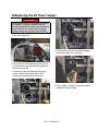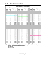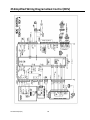
1
Solstice Electric Fryers SELV Series Service M anual RETAIN AND STORE THIS MANUAL IN A SAFE PLACE FOR FUTURE USE L22-393 R0 Page 1 ! DANGER ! Improper installation, operation, adjustment, maintenance, all alterations or service, and unauthorized alterations or modifications can cause property damage, injury or death. Read the installation, operating and service manuals thoroughly before installing or servicing this equipment. ! DANGER ! Prior to moving, testing, maintaining or repairing your appliance, ensure it is emptied of all oil, cool, disconnected from electric and all electrical power. Failure to do so may result in property damage, damage to your fryer, injury or death. ! DANGER ! DO NOT sit or stand on this appliance. The appliance’s top deck, door, front panel, tank, splash back, tank cover, workshelf, drain board are not steps. Serious injury will result from slipping, falling or contact with hot liquids causing property damage, injurious severe burns and/or death. ! DANGER ! NEVER use the appliance as a step for cleaning or accessing the ventilation hood. Serious injury will result from slipping, falling or contact with hot liquids causing property damage, injurious severe burns and/or death. ! DANGER ! Do not store or use electricoline, store or spray aerosols or other flammable liquids or vapors in the vicinity of this or any other appliance. Appliances incorporate open flames and/or high heat that will ignite flammable vapors causing property damage, injury and death. ! DANGER ! No structural material on the fryer should be altered or removed to accommodate placement of the fryer under a hood. ! DANGER ! All fryers shipped without factory supplied cords and plug assemblies must be hardwired using flexible conduit to the terminal block located on the rear of the fryer. These fryers should be wired to NEC specifications. Hardwired units must include installation of restraint devices. ! DANGER ! Adequate means must be provided to limit the movement of this appliance without depending on or transmitting stress to the electrical conduit. ! DANGER ! This appliance has a power cord (three-phase) for each frypot. Prior to movement, testing, maintenance and/or any repair on your appliance; disconnect ALL electrical power cords from the electrical power supply. ! DANGER ! This appliance must be connected to a power supply having the same voltage and phase as specified on the rating plate located on the inside of the appliance door. L22-393 R0 Page 2 ! DANGER ! The contents of the crumb catch and/or filter pan of any filter system must be emptied into a fireproof container at the end of the frying operation each day. Some food particles can spontaneously combust into flames if left soaking in certain oil/shortening materials, causing fire, property damage, injury and death. ! DANGER ! Any and all spilled oil, water or other liquids that occurs as a result of operation, cleaning, maintenance or repair of this fryer should immediately be cleaned and dried. Failure to do so can create a slippery surface resulting in falling/impact injury or death. ! DANGER ! This fryer must not be modified to serve as a water-bath unit. This is especially dangerous if adjoining frypots are used for conventional frying. Water splashing or falling into hot oil causes dangerous eruptions in the oil. Personnel near the fryer can be seriously injured. ! DANGER ! Do not operate this equipment unless all covers and access panels are in place and properly secured. ! DANGER ! Building codes prohibit a fryer with its open tank of hot oil being installed beside an open flame of any type, including those of broilers and ranges. ! DANGER ! Never operate the appliance with an empty frypot. The frypot must be filled to the fill line with water or cooking oil before energizing the elements. Failure to do so will result in irreparable damage to the elements and may cause a fire. ! DANGER ! Never set a complete block of solid shortening on top of heating elements. To do so will damage the elements and increase the potential for flash-point shortening temperatures and subsequent fire. ! WARNING ! DO NOT use the filter pan to transport oil, hot or cold. The filter pan is not designed to transport oil. Serious injury will result from slipping, falling or contact with hot liquids causing property damage, injurious severe burns and/or death. ! WARNING ! DO NOT remove frypot fittings before all oil is drained from the tank. Serious injury will result from slipping, falling or contact with hot liquids causing property damage, injurious severe burns and/or death. ! WARNING ! For appliances equipped with manual (opposed to automated) filtration, shut down the appliance completely when the shortening, fat or oil is being drained from the appliance. This will prevent the appliance inadvertently heating up during the draining and filtering process. L22-393 R0 Page 3 ! WARNING ! This appliance must be installed and used in such a way that any water cannot contact the fat or oil. Water will react violently with hot fat or oil causing severe burns, injury or death. ! WARNING ! Keep all items and hands out of drains. Automated actuators may close without notice causing damage to the fryer and personal injury. ! WARNING ! This appliance is NOT jet stream approved. Do not clean the appliance with a water jet. Use of any pressurized water jet will cause damage to the fryer and personal injury. ! WARNING ! This appliance is intended for indoor use only. Do NOT use outdoors. ! WARNING ! This appliance is not intended for use by persons (including children) with reduced physical, sensory or mental capabilities, or lack of experience and knowledge. Property damage, personal injury or death can result from unqualified operators. ! WARNING ! If the electrical power supply cord is damaged, it must be replaced by a Pitco Authorized Service Agent or a similarly qualified person in order to avoid a hazard. ! WARNING ! Always fill both sides of a split-pot vat when heating for any purpose, testing, cooking or boiling out the vats. ! WARNING ! All wiring connections for this appliance must be made in accordance with the wiring diagram(s) furnished with the appliance. Refer to the wiring diagram(s) in the rear of this manual when installing or servicing this equipment ! CAUTION ! Use caution and wear appropriate safety equipment to avoid contact with hot oil or surfaces. Hot oil and surfaces can cause severe burns and injury. ! CAUTION ! Do not bang fry baskets or other utensils on the joining strips between batteried fry pots. Banging frybaskets or any other utensil on the joining strip will distort and promote oil migration inside the fryer. ! CAUTION ! NEVER run water through the filter pump. Water will damage the pump seals and render the pump inoperable/ It will also void the warranty on the filter pump. L22-393 R0 Page 4 NOTE When installed, this appliance must be electrically grounded in accordance with local codes, or in the absence of local codes, with the National Electrical Code, ANSI/NFPA 70, the Canadian Electrical Code, CSA C22.2, or the appropriate national code of the country in which installed. NOTE If this equipment is wired directly into the electrical power supply, a means for disconnection from the supply having a contact separation of at least 3-mm in all poles must be incorporated in the fixed wiring. NOTE This equipment must be positioned so that the plug is accessible unless other means for disconnection from the power supply (e.g., a circuit breaker) is provided. NOTE If this appliance is permanently connected to fixed wiring, it must be connected by means of copper wires having a temperature rating of not less than 167°F (75°C). NOTE Some US states require any electrical appliance to be installed by a state licensed electrician. Check with your local municipality prior to installation. NOTE This equipment must be installed in accordance with appropriate local and national codes in the state, country and/or region in the appliance is to be operated. Contact your local electric authority for guidance. NOTE This equipment is to be installed in compliance with the basic plumbing code of the Building Officials and Code Administration International (BOCA) and the Food Service Sanitation Manual of the U.S Food and Drug Administration. NOTE Photos and drawings used in this manual are intended to illustrate operational, cleaning and technical procedures and may not conform to onsite management operational procedures. NOTE This appliance is intended to be used for commercial applications: For example in kitchens of restaurants, canteens, hospitals and in commercial enterprises such as bakeries, butcheries, etc. but NOT for continuous mass production of food. NOTE This appliance is intended for professional use only and is to be operated by qualified, trained personnel only. A Pitco Authorized Service Agent (ASA) or other qualified professional must perform installation, maintenance and repairs. Installation or repairs by unqualified personnel will void the manufacturer’s warranty. See chapter one for descriptions of qualified personnel. NOTE If, during the warranty period, the end user uses a part for this Pitco appliance other than an UNMODIFIED new part purchased directly from Pitco or any of Pitco’s authorized service agents, and/or the part being used is modified from its original configuration, THE WARRANTY WILL BE VOID. Further, Pitco Frialator and its affiliates will not be liable for any claims, damages or expenses incurred by the customer which arise directly or indirectly, in whole or in part, due to the installation of any modified part and/or part received from an unauthorized servicer/supplier. L22-393 R0 Page 5 1 Notice In the event of problems or questions about your order, contact the Pitco Frialator factory at (603) 225-6684. For non-routine maintenance or repairs, or for service information, contact your local Pitco Frialator Authorized Service and Parts representative (ASAP). In order to assist you quickly,your Pitco Frialator ASAP or Service Department representative requires certain information about your equipment. Most of this information is printed on a data plate affixed to the inside of the fryer door. Part numbers are found in the Service and Parts Manual. Parts orders may be placed directly with your local ASAP or distributor. A list of Pitco Factory Authorized Service and Parts is located on the Pitco Frialator website at www.pitco.com. If you do not have access to this list, contact the Pitco Frialator Service Department at (603) 225-6684 or by email at: Literature Fulfillment (brochures, spec sheets, manuals) [email protected] Non-urgent service parts inquires. i.e. (part numbers or reference information) [email protected] Non-urgent technical service questions [email protected] Non-urgent warranty questions [email protected] MAILING ADDRESS Pitco Frialator P.O. Box 501 Concord, NH 03302-0501 SHIPPING ADDRESS Pitco Frialator 10 Ferry Street Concord, NH 03301 EQUIPMENT REFERENECE INFORMATION Model #: __________________________ Serial #: __________________________ Date Purchased: ___________________ L22-393 R0 Page 6 TABLE OF CONTENTS 1 2 Notice .............................................................................................................................. 6 General ............................................................................................................................ 9 2.1 Serial Numbers...................................................................................................................... 10 2.2 Safety Information ................................................................................................................ 11 2.2.1 Installation, Operating, and Service Personnel ................................................................. 11 2.3 Definitions............................................................................................................................. 11 2.3.1 Qualified and/or Authorized Operating Personnel ........................................................... 11 2.3.2 Qualified Installation Personnel ........................................................................................ 11 2.3.3 Qualified Service Personnel .............................................................................................. 12 2.4 Shipping Damage Claim Procedure ...................................................................................... 12 3 Theory of Operation ....................................................................................................... 12 3.1 The Heating System .............................................................................................................. 13 3.2 Hi-Limit System.................................................................................................................... 13 3.3 Auto Filtration Boards .......................................................................................................... 14 3.4 Thermostats ........................................................................................................................... 16 3.5 Fryer Sequence Operation..................................................................................................... 16 3.6 Filter System (Manual Filtration Only) ................................................................................ 16 3.7 Basket Lift (Optional) ........................................................................................................... 17 3.8 Auto Top Off – ATO (Optional)........................................................................................... 17 3.9 Automated Filtration (Optional) ........................................................................................... 18 4 Accessing Fryer for Servicing ........................................................................................ 19 4.1 Removing the Controller Front Panel Bezel ......................................................................... 20 4.2 Removing the Entrance Box Covers ..................................................................................... 21 4.3 Manual Operation of Drain and Return (Auto Filter Only) .................................................. 22 5 Removing the Entrance Box Wire Guard ....................................................................... 23 6 Blocked Drain (Auto Filter Only) .................................................................................... 24 6.1 Diagram Identifying Terminals for Second Resistance ........................................................ 25 6.2 Checking the Resistance of the DVI Switch ......................................................................... 25 6.3 Checking the Resistance of the Hi-Limit .............................................................................. 26 6.4 Checking the Resistance of the Probe ................................................................................... 27 7 Replacing the Relay Board and Paper .......................................................................... 28 8 Replacing Hi-limit Switch and/or Sensing Probe............................................................ 30 9 Replacing Drain Valve with Actuator (Auto Filter Only) ................................................. 31 10 Replacing the DC Power Supply ................................................................................... 33 10.1 Replacing the DC Power Transformer Box .......................................................................... 34 11 Changing Filter Pump Actuator...................................................................................... 35 12 Testing the Auto Top Off Probe (if equipped) ................................................................ 36 12.1 Replacing Oil Top off Probe ................................................................................................. 38 13 Replacing the Return Valve ........................................................................................... 39 14 Replacing the Basket Lift Components .......................................................................... 40 14.1 Removing the Basket Lift Cover .......................................................................................... 40 14.2 Replacing the Basket Lift Transformer................................................................................. 40 14.3 Replacing the Basket Lift Driver Board ............................................................................... 41 14.4 Adjusting the Magnetic Sensor ............................................................................................. 42 14.5 Replacing the Basket Lift Actuator....................................................................................... 42 Filter System .............................................................................................................. 44 L22-393 R0 Page 7 15 Replacing the Flush Hose Assembly and Valve ............................................................ 45 15.1 Replacing the Optional Flush Hose Assembly and Valve .................................................... 48 16 Replacing the Waste Oil and Components .................................................................... 51 16.1 Removing Rear Mounting Bracket ....................................................................................... 51 16.2 Removing the Check Valve .................................................................................................. 52 17 Replacing the Filter Pump and Motor ............................................................................ 54 17.1 Removing the Filter Pump and Motor .................................................................................. 54 17.2 Replacing Seal Kit ................................................................................................................ 57 17.3 Removing the Filter Pump from the Motor .......................................................................... 58 18 Replacing the Pump Relay and Circuit Breaker............................................................. 59 18.1 Replacing the Circuit Breaker ............................................................................................... 59 18.2 Replacing the Pump Relay .................................................................................................... 60 18.3 Replacing the Drain Line or Electricket ............................................................................... 61 Troubleshooting and Problem Isolation ..................................................................... 62 19 Replacing High Limit (Side On) Contactor ..................................................................... 63 19.1 Replacing Heat Demand and Transformer ........................................................................... 64 20 Replacing the DVI Switch .............................................................................................. 66 21 Replacing the Frypot ..................................................................................................... 67 22 Replacing the Element .................................................................................................. 72 23 Troubleshooting and Problem Isolation ......................................................................... 75 24 Component Troubleshooting ......................................................................................... 75 24.1 Probe ..................................................................................................................................... 75 24.2 HD Contactor ........................................................................................................................ 75 24.3 Side On Safety Contactor...................................................................................................... 75 24.4 Context Removed.................................................................................................................. 75 24.5 Drain Valve and Return Valve Switches .............................................................................. 76 24.6 Transformer........................................................................................................................... 76 24.7 Elements ................................................................................................................................ 76 24.8 Relay Board .......................................................................................................................... 77 24.9 Computer Control ................................................................................................................. 77 24.10 Probe Resistance Chart ..................................................................................................... 78 Wiring Diagrams ........................................................................................................ 79 25 Simplified Wiring DiagramsHeat Control (ROV) ............................................................ 80 25.1 Auto-Filter Control (ROV) ................................................................................................... 81 25.2 Control Power Supply (ROV) ............................................................................................... 82 25.3 US and Canada Wiring Diagrams (Controls) ....................................................................... 83 25.4 US and Canada Wiring Diagrams (Replacement Parts List) ................................................ 84 25.5 US and Canada Wiring Diagrams (Basket Lift Option) ....................................................... 85 25.6 US and Canada Wiring Diagrams (Filter Pump Option) ...................................................... 86 25.7 US and Canada Wiring Diagrams (Single Phase Twin Vat) ................................................ 87 25.8 US and Canada Wiring Diagrams (Single Phase Full Vat) .................................................. 88 25.9 US and Canada Wiring Diagrams (3 Phase Full Vat)........................................................... 89 25.10 Export and CE Wiring Diagrams (Filter Pump Option) ................................................... 90 25.11 Export and CE Wiring Diagrams (Single Phase Twin Vat) ............................................. 91 25.12 Export and CE Wiring Diagrams (Single Phase Full Vat) ............................................... 92 25.13 Export and CE Wiring Diagrams (3 Phase Full Vat) ........................................................ 93 L22-393 R0 Page 8 25.14 25.15 Export and CE Wiring Diagrams (3 Phase Twin WYE Vat)............................................ 94 Export and CE Wiring Diagrams (3 Phase Twin Delta Vat) ............................................ 95 2 General Read the instructions in this manual thoroughly before attempting to operate this equipment. This manual covers all configurations of Pitco SELV electric models. The fryers in this model family have most parts in common, and when discussed as a group, will be referred to as SELV fryers. The SELV fryers feature a low oil volume frying vat, optional automatic oil top off and optional automated filtration unit. The Solstice design features a large round drain, which ensures that fries and other debris will be washed into the filter pan. The SELV fryers are controlled with an I12 + Controller. Fryers in this series come in full- or split-vat arrangements, and can be purchased in batteries of up to five fryers. L22-393 R0 Page 9 2.1 Serial Numbers NOTE If, parts returned to the factory under warranty are found to be a functional/serviceable, Pitco may, at its discretion, decline warranty reimbursement and may charge for replacement parts. L22-393 R0 Page 10 2.2 Safety Information Before attempting to install, operate or service your unit, read the instructions in this manual thoroughly. Throughout this manual, you will find notations enclosed in shaded boxes similar to the one below. ! DANGER ! Clean up any spilled oil or shortening immediately. Oil or shortening left on the floor creates a slipping hazard that will result in personal injury sustained from falling. NOTE NOTE boxes contain especially important information. ! CAUTION ! CAUTION boxes contain information about actions or conditions that may cause or result in a malfunction of your system and/or minor personal injury. ! WARNING ! WARNING boxes contain information about actions or conditions that may cause or result in damage to your system and/or moderate personal injury, and which may cause your system to malfunction. ! DANGER ! DANGER boxes contain information about actions or conditions that may cause or result in serious injury or death to personnel, and which may cause damage to your system and/or cause your system to malfunction. 2.2.1 Installation, Operating, and Service Personnel Operating information for Pitco equipment has been prepared for use by qualified and/or authorized personnel only, as defined in Section 2.3. All installation and service on Pitco equipment must be performed by qualified, certified, licensed, and/or authorized installation or service personnel, as defined in Section 2.3.2. 2.3 Definitions 2.3.1 Qualified and/or Authorized Operating Personnel Qualified/authorized operating personnel are those who have carefully read the information in this manual and have familiarized them themselves with the equipment functions, or who have had previous experience and/or training with the operation of the equipment covered in this manual. 2.3.2 Qualified Installation Personnel Qualified installation personnel are individuals, firms, corporations, and/or companies which, either in person or through a representative, are engaged in and are responsible for the installation of electrical appliances. Qualified personnel must be experienced in such work, be familiar with all electrical precautions involved, and have complied with all requirements of applicable national and local codes. L22-393 R0 Page 11 2.3.3 Qualified Service Personnel Qualified service personnel are those who are familiar with Pitco equipment and who have been authorized by Pitco Frialator to perform service on the equipment. All authorized service personnel are required to be equipped with a complete set of service and parts manuals, and to stock a minimum amount of parts for Pitco equipment. Failure to use qualified service personnel will void the Pitco warranty on your equipment 2.4 Shipping Damage Claim Procedure What to do if your equipment arrives damaged: Please note that this equipment was carefully inspected and packed by skilled personnel before leaving the factory. The freight company assumes full responsibility for safe delivery upon acceptance of the equipment. 1. File Claim for Damages Immediately - regardless of extent of damage. 2. Inspect For and Record All Visible Loss or Damage, and ensure that this information is noted on the freight bill or express receipt and is signed by the person making the delivery. 3. Concealed Loss or Damage- If damage is unnoticed until equipment is unpacked, notify the freight company or carrier immediately upon discovery and file a concealed damage claim. This must be submitted within 15 days of date of delivery. Be sure to retain container for inspection. PITCO DOES NOT ASSUME RESPONSIBILITY FOR DAMAGE OR LOSS INCURRED IN TRANSIT. 3 Theory of Operation SELV Series electric fryers utilize a welded, stainless steel fryvat that is directly heated with high efficiency, ribbon style heating elements. Ribbon style elements offer a lower watt density per square inch and are gentler on the oil. The elements rotate upward for easy cleaning. In full-vat units, heat demand to the elements is regulated by one electromechanical contactor. In split-vat units, each element bank has its own contactor to independently control each vat. All fryers in this series are equipped with 24 V AC control circuits, and the elements can be configured to accommodate a wide range of electrical supply. L22-393 R0 Page 12 3.1 The Heating System A hi-limit device located in the fry vat provides an additional level of operator safety. If the high limit is satisfied that the fryer is operating within design parameters, a “side on” contactor will close and stay closed so long as the cooking oil temperature stays below a specified limit. This safety circuit minimizes the operations of the “side on” contactor to insure it can open in the unlikely event of a run away condition. The “side on” contactor is wired in parallel with the “heat demand” contactor to deliver main power to the heating elements. The heat demand contactor is controlled via the I12+ control board which responds to input from a thermistor located in the fryvat. When the thermistor transmits a temperature reading below the desired cook temperature, the I12+ closes the heat demand contactor completing the circuit to supply electrical energy to the hating elements until the oil temperature matches the desired cooking temperature. Should the high limit trip, it cannot be reset until the oil temperature falls below the hi-limit threshold, so the unit needs to cool. The cause of the hi-limit tripping should be investigated and corrected prior to putting the fryer back into service. The unit is connected to line voltage: If Fuse F1 on the relay board is good: The A.C. indicator is illuminated. The controller is supplied with 24 VAC. With the drain valve handle closed, the proximity switch supplies 24 VAC to the drain valve interlock (DVI) input at the controller. 24 VAC is at the Side On (SO) relay COM contact. The controller is turned ON: The SO indicator on the relay board is illuminated. The SO relay is energized, closing the circuit. The safety (SO) contactor energizes if the hi-limit is not tripped. 3.2 Hi-Limit System If the hi-limit trips: The SO and HD contactors lose 24 VAC supply and the HFB loses 24 VAC. The computer displays “HEATING”. The HD lamp is illuminated on the Back-up T-stat and the HFB lamp is not illuminated. After the hi-limit resets (unit cools to 375°F ±20°F (191°C ±20°C)), turn the controller off and then back on for the unit to heat. L22-393 R0 Page 13 3.3 Auto Filtration Boards All fryers in this series have an Auto-Filtration Board (AFB) located in the component box behind the control bezel. The AFB provides a “bus” between the controller and the fryer's individual components without requiring additional wiring by using a communication protocol over a twisted pair, and allows the controller to execute commands from one central point. The heat control circuit is show below in Figure 1. This is the bottom left corner of the AFB. For a split vat, this is duplicated on the bottom right hand corner. Figure 1 - Bottom left corner of Auto Filtration Board L22-393 R0 Page 14 Figure 2 - Auto-Filtration Board (AFB) L22-393 R0 Page 15 3.4 Thermostats SELV Series electric fryers have temperature probes located between the heating elements in the center, bottom of the vat. In a full vat, the temperature probe is on the right bank of elements. There is always one in each vat, full or split. SELV fryers, like all Solstice series fryers, use a thermistor style temperature probe. In this type of thermostat, the probe resistance varies directly with the temperature. That is, as the temperature rises, so does resistance. Circuitry in the controller monitors the probe resistance and controls heat demand contactor when the resistance exceeds or falls below programmed temperatures (setpoints). SELV Series electric fryers are also equipped with a high-limit thermostat. In the event that the fryer fails to properly control the oil temperature, the high-limit thermostat prevents the fryer from overheating to the flash point. The high-limit thermostat acts as a normally closed power switch that opens when exposed to temperatures above 425°F to 450°F (218°C to 232°C). 3.5 Fryer Sequence Operation The SELV fryer components function in specific order of operation. Knowing and understanding the sequence of fryer and components operation enables you to diagnose equipment failure more accurately. 3.6 Filter System (Manual Filtration Only) Pulling the BLUE drain valve handle will: Open the drain at the bottom of the fry vat Open the “Drain Valve Interlock” (DVI) magnetic switch disabling the heating system during filtration. !WARNING! Inspect the filter pan prior to pulling the BLUE DRAIN VALVE HANDLE to insure it is empty. If the filter pan has visible oil, opening the valve will result in hot oil overflow onto the floor resulting in slipping hazards, fall related injuries, serious burns or death. Push handle in to close Drain and enable DVI. Pulling the RED (If Equipped) return valve handle: Opens the return valve to that vat. Closes the pump proximity switch causing the “pump run” relay to be energized. The pump motor begins to run. Closing the return valve handle de-energizes the relay and the pump motor stops running and the return valve closes. The pump system is equipped with a circuit breaker which de-energizes the system and the heat tape (If equipped) in the event of over current. The circuit breaker must be in the “ON” position for the pump and heat tape to operate. NOTE Circuit Breaker should remain in the “ON” position at all times. Pulling the BROWN waste oil valve will: (If equipped): Divert oil flow from the pump to the fry vat to user supplied waste oil plumbing through a Pitco supplied three way valve.The return piping system may be provided with optional heat tape to prevent solidification of solid shortening. The heat tape is low wattage and is on constantly to maintain liquid shortening in the line. L22-393 R0 Page 16 3.7 Basket Lift (Optional) The basket lift is a self contained unit that requires a 120V, 208V, or 240V supply. With most fryer configurations, the power is supplied from the entrance box at the back of the fryer, but some configurations require power directly from a wall outlet. When power is supplied to basket lift assembly, the baskets lift to the up position. The baskets lower with a 24 VDC output from the controller. The basket lift control voltage is supplied from the controller The basket lift operational voltage is supplied from the line voltage supply that powers the transformer in the basket lift assembly. 3.8 Auto Top Off – ATO (Optional) If equipped, the optional Auto Top Off (ATO) adds small doses of oil from the “Jug in Box” or JIB when low oil conditions are detected. During frying, small amounts of oil are absorbed (called “drag out”) by the food and removed from the fryer. These small amounts eventually lead to replenishment with a “Top Off” event. The fryer cannot be filled from empty with the Auto Top Off option. The ATO uses the filter pump to move oil from the JIB to the fry vat when low oil conditions are sensed. A linear actuator redirects the pump flow from the JIB during a Top Off event. The ATO doesn’t not operate during a cook cycle to keep the oil hot during cooking. Adding room temperature oil during cooking would negatively impact the cook cycle and product. The ATO probe is located on the rear wall of the fry tank as pictured below: The ATO probe plugs into the Auto Top Off relay board behind the front control bezel. The following conditions must be met for the ATO event to occur: The vat must be in idle condition, not cooking or melting, with display showing “Ready” or “Drop”. This display typically shows when the vat is within 20°F of cooking set-point. L22-393 R0 Page 17 When the cooking control shows Ready, the oil level probe will take time to detect the low level condition. The lower the level the faster the response. The reverse is also true. Modestly low levels take longer to resolve. (< 3/8” below probe). Levels ½” below probe should detect in 3-1/2 minutes or less. Drain Valve Actuator (top) with Drain Valve (below) 1 Linear Actuator 1 Food debris, or oil caked onto probe may prevent ATO operation. Occasional probe cleaning when vat is empty and cool is recommended. Top off does not occur when the control is Off, Melting, Cooking, or Heating. 3.9 Automated Filtration (Optional) If equipped with an Automated Filtration system, the filtration works like any other Solstice Fryer except the manual handles (blue and red) are replaced with actuators (show above) to drain the fry vat and return oil to fry vat after filtering. The Automated Filtration system does not actuate “automatically”, user input is required. The actuators for the drain valve and return valve can be manually operated through the I12 computer. (See Section this manual,9) When a pre-determined threshold (typically a user programmed number of cooks) is reached, the operator can be prompted to filter the cooking oil. Upon successful operator input, the system: Begins an automated filtration process that first opens the drain valve and drains the oil into the filter pan. Shortly after the drain valve opens, the linear actuator opens the return valve and the filter pump actuates. The filtering process operates for a pre-defined period of time (user programmable) The drain valve closes and the pump continues to run, returning the freshly filtered oil to the fry vat. When timer reaches zero all the oil has been pumped back to the fry vat, the pump turns off and the return valve closes. The operator is queried to insure the vat is full. If the operator responds “NO”, the filter pump turns on for 20 seconds and the return valve is opened to pump any remaining oil from the filter pan. When the operator responds “YES”, the fryer turns itself off and must be re-energized by the operator pressing the “ON” key to restore power and begin frying. L22-393 R0 Page 18 4 Accessing Fryer for Servicing 2. Unplug all power cords if equipped, there is one for each vat. Actual plug may vary from photo below. ! DANGER ! Prior to moving, testing, maintaining or repairing your appliance, ensure it is emptied of all oil, cool, disconnected from all electrical power. Failure to do so may result in property damage, damage to your fryer, injury or death. 1. Press off button on control panel. 3. If fryer is not equipped with power cords, open (turn off) the circuit breaker or power disconnect for each frying vat. The power switch or circuit breaker may not be located directly behind the fryer(s), check circuit breaker boxes located in the kitchen. !WARNING! Before starting work, double check that the correct power switch/disconnect was turned off by turning ON the control panel located on the front bezel of the fryer (shown in photo to left). If the control panel does not respond, it’s safe to proceed. If the control panel turns on, the correct power switch/disconnect needs to be turned off before proceeding with work L22-393 R0 Page 19 4.1 Removing the Controller Front Panel Bezel 1. Remove the two (2) screws on the controller panel using a Phillips screwdriver. (on a Dual unit you will need to remove the front panel divider). 3. Disconnect the controller wiring harness. (For a dual unit- remove the front panel divider) 2. Pull out the controller panel front bezel. L22-393 R0 Page 20 4.2 Removing the Entrance Box Covers 1. Remove the two (2) screws on the entrance box lower cover located on the left side of the unit using a Philips screwdriver. 2. Remove the four (4) screws entrance box lower cover located on the right side of the unit using a Philips screwdriver. 3. Remove the two (2) screws on the entrance box upper cover using a Philips screwdriver. 4. Follow steps 1 through 3 in reverse to reinstall the entrance box covers. L22-393 R0 Page 21 4.3 Manual Operation of Drain and Return (Auto Filter Only) 1. To open and/or close drain or return oil from filter pan manually, hold center filter button until display changes to fryer control (can be done with fryer on/off). 2. Pressing “L” key brings up the return mode, Pressing “Yes” key activates the motor and allows the pump to return oil from the filter pan to the vat. The pump/motor will remain on until you press “yes” key again to toggle off. 3. Pressing the “1” key brings up drain toggle option- press “YES” to open drain – drain will remain open until “YES” key is pressed again to toggle drain closed. ! DANGER ! Any and all spilled oil, water or other liquids that occurs as a result of operation, cleaning, maintenance or repair of this fryer should immediately be cleaned and dried. Failure to do so can create a slippery surface resulting in falling/impact injury or death. L22-393 R0 Page 22 5 Removing the Entrance Box Wire Guard 1. Remove the two (2) screws on the wire guard using a 5/16” inch hex wrench. 3. Follow steps 1 through 2 in reverse to reinstall the entrance wire guard. 2. Slide the wire guard down to remove. L22-393 R0 Page 23 6 Blocked Drain (Auto Filter Only) 1. Display of “Blocked Drain- retry”. The drain is not closing and the controller is not receiving the signal that shows that the drain has been closed. NOTE Use ONLY the supplied drain cleaning tool to remove any food debris or foreign object from drain. Use of any other tool can damage your drain valve and will void the warranty. 2. Once you cleared the drain press “YES” button (6) key. If drain closes and the controller receives the correct signal, check the drain again to insure the cleaning tool has been removed. Your fryer should go back into normal mode. If not, your controller will scroll “block drain”. You only have 3 times to try and unblock drain before controller goes into lock out. 4. If at any time you push “N” (0) key another scrolling message “FRYER WILL BECOME INOPERABLE”, “CONFIRM SHUT DOWN” message. 5. If you press the “N” (0) key then the message will revert to the display “Blocked Drain” as in number 1. If you press the “Y” (6) key message will display “Call Service – ERR” the fryer will no longer operate. If a multi fryer system the other fryers shouldn’t be effected by this error. ! WARNING DO NOT UNPLUG FRYER FROM SUPPLY POWER. If the unit is unplugged and plugged in again, you WILL damage your drain valve and void the warranty. 3.If after three tries, the drain is still blocked the fryer will no longer operate. If you have a multi fryer system, the other fryers shouldn’t be affected by this error. Contact Pitco Service or Authorized Service Person for assistance. There is NO reset from front controller panel. L22-393 R0 Page 24 6.1 Diagram Identifying Terminals for Second Resistance PP10429 Secondary Resistance TAP Volts Resistance 10 ‐ 6 24V 0.7 PP10428 Secondary Resistance TAP Volts Resistance 10 ‐ 6 24V 0.6 Primary Resistance Volts Resistance 240V 30.4 208V 25.3 120V 9.9 Primary Resistance Tap Volts Resistance 5 ‐ 1 480V 119.5 5 ‐ 2 440V 107.7 5 ‐ 3 380V 90.2 Tap 5 ‐ 1 5 ‐ 2 5 ‐ 3 6.2 Checking the Resistance of the DVI Switch 1. Remove the DVI connection. 2. Connect the multimeter to the DVI leads and check the resistance. DVI Resistance Table Valve Closed Valve Open Near Zero Ohm Open Circuit L22-393 R0 Page 25 6.3 Checking the Resistance of the Hi-Limit 1. Remove the Hi-Limit connection. 2. Connect the multimeter to the Hi-limit leads and check the resistance. L22-393 R0 Page 26 6.4 Checking the Resistance of the Probe 1. Remove the probe connection. 2. Connect the multimeter to the thermostat leads and check the resistance. See “Probe Resistance Chart” on page 78. L22-393 R0 Page 27 7 Replacing the Relay Board and Paper 1. Remove the front panel. See “removing the Controller Front Panel Bezel page 20”. ! DANGER ! Prior to moving, testing, maintaining or repairing your appliance, ensure it is emptied of all oil, cool, disconnected from all electrical power. Failure to do so may result in property damage, damage to your fryer, injury or death. 2. Press off button on control panel. disconnect for each frying vat. The power switch or circuit breaker may not be located directly behind the fryer(s), check circuit breaker boxes located in the kitchen. !WARNING! Before starting work, double check that the correct power switch/disconnect was turned off by turning ON the control panel located on the front bezel of the fryer (shown in photo to left). If the control panel does not respond, it’s safe to proceed. If the control panel turns on, the correct power switch/disconnect needs to be turned off before proceeding with work. 5. Disconnect all connections 3. Unplug all power cords if equipped, there is one for each vat. Actual plug may vary from photo below. 6. Remove the seven (7) screws which hold down the relay board, using a small flathead screwdriver. 4. If fryer is not equipped with power cords, open (turn off) the circuit breaker or power 7. Remove the relay board and flip it over. L22-393 R0 Page 28 8. Remove the existing insulator and replace with a new insulator. NOTE: Make sure the insulator doesn’t have puncture marks in it, if so replace with another piece without puncture marks. 9. Reinstall by following steps 1 through 8 in reverse L22-393 R0 Page 29 8 Replacing Hi‐limit Switch and/or Sensing Probe 1. Remove the cabinet back cover. Using 5/16 socket remove eight (8) screws. 4. Remove element rack by removing fifteen (15) screws using a phillips screw driver. 2. Remove two (2) screws from hi-limit switch box in rear using a Phillips screw driver. 5. Unplug Molex connector for hi-limit switch and/or sensing probe. Pull out sensing probe. 3. In front, remove ten (10) screws holding two (2) element bands using a flat tip screw driver. 6. Replace with new hi-limit switch and/or sensing probe by following steps 1 through 5 in reverse. Right Tank Left Tank L22-393 R0 Page 30 9 Replacing Drain Valve with Actuator (Auto Filter Only) ! DANGER ! Prior to moving, testing, maintaining or repairing any appliance, ensure it is emptied of all oil, cool, disconnected from electric and all electrical power. Failure to do so may result in property damage, damage to your fryer, injury or death. 4. Using a 3/32 inch T handle hex key, loosen the mounting screws on the drain actuator. Remove the access panel rear of unit, unplug Molex connector for actuator. Once unplugged, slide the actuator off. 1. Pitco ROV fryer with automated filtration uses a 24 VDC drain actuator for opening /closing the drain for each pot. 5. Follow steps 1 through 4 in reverse order to reinstall Actuator. Remember to remove the rag or paper towels from the drain. ! DANGER ! 2. On the far left unit remove rubber protection on thread of retaining clamp screw. Remove the 2 bolts holding drain elbow in place. Loosen the retaining clamp holding the drain piping together and remove the drain elbow. Any and all spilled oil, water or other liquids that occurs as a result of operation, cleaning, maintenance or repair of this fryer should immediately be cleaned and dried. Failure to do so can create a slippery surface resulting in falling/impact injury or death. 6. Make sure the red electricket is positioned between the elbow and drain tube where they join, slide retaining clamp over red electricket with position nut at bottom of drain line and tighten. 3. Once the elbow is removed, a small amount of oil will dip from drain, place a rag or paper towel in drain. L22-393 R0 Page 31 7. Don’t forget gray rubber protector on the thread of the clamp so they don’t get damaged. NOTE When reassembling the actuator and valve, remember to have the arrows in the motor socket align with the end of the valve stem slot. The valve and the actuator are indexed to operate properly. Failure to align the index marks will result in the valve being opened when it supposed to be closed, and vice-versa. 8. After servicing the powered drain system, If the drain remains open, the motor and valve assembly are not indexed correctly, remove motor, and align marks as instructed. 9. Should the drain valve need to be replaced, first remove actuator per instruction in section 4 of this chapter (drain valve comes with actuator installed), then remove the old drain valve from the end of the drain nipple and install the new drain valve and actuator. NOTE When installing the new drain valve, insure the arrow on the valve body is pointed AWAY from the drain nipple and towards the filter pan. L22-393 R0 Page 32 10 Replacing the DC Power Supply ! DANGER ! Prior to moving, testing, maintaining or repairing any appliance, ensure it is emptied of all oil, cool, disconnected from electric and all electrical power. Failure to do so may result in property damage, damage to your fryer, injury or death. 1. Remove the one (1) 5/16 inch hex screw on front of mounting box. 4. You can easily remove entire mounting box and power supply all in one piece. 2. From the rear of the unit remove two (2) 5/16 hex screws from the small bracket that holds the hose for the JIB. 3. In the rear of the unit disconnect the black power cord from the entrance box, also remove the red/black Molex connector. 5. Follow steps 1 through 4 in reverse order to reinstall DC Power Supply. L22-393 R0 Page 33 10.1 Replacing the DC Power Transformer Box Remove the front panel (see “Removing the Controller Front Panel page 20). 2. Remove the two (2) screws on the transformer box using a Philips screw driver. 1. Remove the four (4) terminal connections. 3. Remove transformer box from the unit. Transformer Wiring NOTE: Wire according to the appropriate voltage. 4. Follow steps 1 through 3 in reverse to install the new transformer. L22-393 R0 Page 34 11 Changing Filter Pump Actuator 1. Pull two (2) re-usable cotter pins. One is located in the front of the actuator unit, second is located in the rear of the actuator. 2. From the front, unplug the four pin molex connector for the actuator. 3. Remove filter pump actuator. 4. Follow steps 1 through 3 in reverse to reinstall new filter pump actuator. NOTE Re-assembly is simplified if the cotter pin in the rear is installed BEFORE the cotter pin in the front of the fryer. L22-393 R0 Page 35 12 Testing the Auto Top Off Probe (if equipped) The Auto Top Off probe should be tested prior to replacement (follows this section). 1. Unplug connector J7 from the Auto Top Off Relay board. Measure the resistance with a multimeter (set to OHMS) between pins 1 and 2. The resistance should be approximately 150 ohms (+/- 2 ohms). Place either probe to the frame of the fryer and insure you have an open circuit (open to frame). If the probe measure outside this range, it must be replaced. NOTE Prior to measuring the probes resistance between pins 4 and 5, insure the fry vat contains enough oil to completely cover the probe. 2. Measure resistance with the multimeter between pins 4 and 5. The meter should read 167 OHMS at 350 degrees F. Measure the resistance with black lead to the frame to insure an open circuit reading (open to frame). a. Resistance is dependent on the probe temperature. At room temperature, the resistance is 108 ohms. At cooking temperatures, the resistance can be as high as 167 ohms. If the probe measures within this range, it’s OK. L22-393 R0 Page 36 L22-393 R0 Page 37 12.1 Replacing Oil Top off Probe ! DANGER ! Prior to moving, testing, maintaining or repairing any appliance, ensure it is emptied of all oil, cool, disconnected from electric and all electrical power. Failure to do so may result in property damage, damage to your fryer, injury or death. 1. Remove the four (4) screws, which hold the cabinet back cover, using a 5/16 inch socket. 4. Replace with new probe following steps 1 through 3 in reverse. 2. Unplug Molex plug. 3. Loosen nut on oil top off probe with a 5/16 inch wrench. L22-393 R0 Page 38 13 Replacing the Return Valve ! WARNING ! DO NOT remove fry vat or drain fittings before all oil is drained from the tank. Serious injury will result from slipping, falling or contact with hot liquids causing property damage, injurious severe burns and/or death. 1. Remove all connections from the 3-way return valve using a 1/16 inch wrench. 2. Remove the cotter pin on return valve using needle-nose pliers. 3. Replace the return valve by following steps 1 through 2 in reverse, replacing the cotter pin if necessary. NOTE Thread sealant is not required for these fittings. L22-393 R0 Page 39 14 Replacing the Basket Lift Components 14.1 Removing the Basket Lift Cover 1. Remove the six (6) screws, which hold the back of the basket lift cover, using a 5/16 inch socket. 2. Lift up the back and remove. 14.2 Replacing the Basket Lift Transformer 1. Remove the two (2) screws, which hold the transformer, using a 5/16 inch socket. 2. Remove all wires on transformer box using needle-nose pliers. Follow steps 1 through 2 in reverse to reinstall new transformer box. L22-393 R0 Page 40 14.3 Replacing the Basket Lift Driver Board 1. Remove all wires on basket lift driver board using needle-nose pliers. 4. Remove the actuator power connection using needle-nose pliers. 2. Remove the sensor connection using needlenose pliers. 5. Remove the four (4) screws, which hold the basket lift driver board, using a Phillips screwdriver. 3. Remove the control signal connection using needle-nose pliers. 6. Follow steps 1 through 5 in reverse to reinstall a new basket lift driver board. L22-393 R0 Page 41 14.4 Adjusting the Magnetic Sensor 1. Make sure the sensor is approximately 3/4 inch from top of the motor to bottom of the sensor. 2. Make sure the sensor is approximately 7 3/4 inch from top of the motor to bottom of the sensor. 14.5 Replacing the Basket Lift Actuator 1. Cut all zip ties on the basket lift driver board. 2. Disconnect the transformer from the driver board. See “Replacing the Basket Lift Driver Board pg 41. 3. Disconnect the upper and lower limit connections on the basket lift driver board. 4. Remove the two (2) bolts, which hold the actuator, using a 3/16 inch Allen key. L22-393 R0 Page 42 8. Rotate up the actuator collar. 5. Remove the top retaining bushing by unscrewing. 9. Remove the actuator collar. 6. Slide the bushing off the shaft. 7. Disconnect the motor connector from the driver board. 10. Follow steps 1 through 9 in reverse to reinstall a new basket lift actuator. L22-393 R0 Page 43 Filter System L22-393 R0 Page 44 15 Replacing the Flush Hose Assembly and Valve 1. Remove the lower connection at the 3-way return valve in the back of the unit using a 15/16 inch wrench. 2. Remove the male quick disconnect using a 15/16 wrench. 4. Remove two (2) screws holding the flush hose assembly using a 5/16 socket. 5. Remove the flush hose assembly. 6. Remove the four (4) screws from the magnets using a flathead screwdriver. 3. Unplug the proximity switch. L22-393 R0 Page 45 7. Remove the two (2) screws from the valve mounting brackets using a 5/16 inch socket. 9. Lift bracket out and slide forward. 10. Bend down tabs of the stem nut washer using a needle-nose plier. 8. Slide the bracket to the back of the assembly. 11. Remove the nut using a 7/16 inch wrench. L22-393 R0 Page 46 12. Remove the handle. 14. Remove the piping using a 15/16 inch wrench on the valve and an adjustable wrench on the piping. 13. Remove the mounting bracket. 15. Replace the flush hose assembly and valve by following steps 1 through 14 in reverse. L22-393 R0 Page 47 15.1 Replacing the Optional Flush Hose Assembly and Valve 4. Remove two (2) screws holding the flush hose assembly using a 5/16 socket. ! DANGER ! Prior to moving, testing, maintaining or repairing your appliance, ensure it is emptied of all oil, cool, disconnected from electric and all electrical power. Failure to do so may result in property damage, damage to your fryer, injury or death. 1. Remove the lower connection at the 3-way return valve in the back of the unit using a 15/16 inch wrench. 5. Remove the flush hose assembly. 6. Remove the four (4) screws from the magnets using a flathead screwdriver. 2. Remove the male quick disconnect using a 15/16 inch wrench. 3. Unplug the proximity switch. L22-393 R0 Page 48 7. Remove the two (2) screws from the valve mounting brackets using a 5/16 socket. 9. Lift bracket out and slide forward. 10. Bend down tabs of the stem nut washer using a needle-nose plier. 8. Slide the bracket to the back of the assembly. 11. Remove the nut using a 7/16 inch wrench. L22-393 R0 Page 49 12. Remove the handle. 14. Remove the piping using a 15/16 inch wrench on the valve and an adjustable wrench on the piping. 13. Remove the mounting bracket. 15. Replace the flush hose assembly and valve by following steps 1 through 14 in reverse. L22-393 R0 Page 50 16 Replacing the Waste Oil and Components 16.1 Removing Rear Mounting Bracket 1. Remove six (6) screws using a 5/16 socket wrench. 3. Remove two (2) screws with a 5/16 socket wrench. ! DANGER ! Prior to moving, testing, maintaining or repairing your appliance, ensure it is emptied of all oil, cool, disconnected from electric and all electrical power. Failure to do so may result in property damage, damage to your fryer, injury or death. 2. Disconnect from the filter return line using a 1-1/16 inch wrench. L22-393 R0 Page 51 16.2 Removing the Check Valve 1. Remove the 3/8 inch nipple using an adjustable wrench. 3. Remove the valve nut using a 9/16 inch open-ended wrench. 2. Remove the second nipple using two adjustable wrenches. 4. Remove the valve lever. L22-393 R0 Page 52 5. Remove the two (2) screws using a Phillips screwdriver. 8. Follow steps 1 through 7 in reverse to reinstall. 6. Lift off the mounting bracket. 7. Remove the valve using two adjustable wrenches. L22-393 R0 Page 53 17 Replacing the Filter Pump and Motor 17.1 Removing the Filter Pump and Motor NOTE Photos are for illustrative purposes only and may not be an exact match to your appliance.. 1. Remove filter pan and filter pan cover. Loosen the pump inlet tube using a crescent wrench. ! DANGER ! Any and all spilled oil, water or other liquids that occurs as a result of operation, cleaning, maintenance or repair of this fryer should immediately be cleaned and dried. Failure to do so can create a slippery surface resulting in falling/impact injury or death. 3. Pull out pump inlet tube. 4. Remove filter pan cover (not shown). 2. Unscrew and remove the inlet valve of the filter pump system. 5. Disconnect the connections and power supply cords from the filter pump. L22-393 R0 Page 54 6. Remove the lower connection at the 3-way return valve using a 15/16 inch wrench. 9. Remove the rear hair pin on the actuator. 7.Using a 1” inch wrench remove the JIB hose. 10.Remove the bracket. 8. Remove one (1) screw, which holds a bracket which is underneath the ON/OFF breaker switch using a 5/16 inch socket. NOTE The filter pump will fall to the floor once the pins are pulled out. It is recommended that you brace the pump and motor before pulling out the pins. L22-393 R0 Page 55 11. Turn down the pins and then pull them out. 12. ROV units with a solofilter, will require the removal of the RH pan guide rail to allow the pump to be lowered as shown (Filter pan rails are not shown). Lower the filter pump to the floor and then pull it out. 14. Remove two (2) screws on back of filter pump using a 5/16 inch socket. 15. Remove existing piping from old filter pump using two adjustable wrenches. 16. Reinstall a new filter pump by following steps 1 through 15 in reverse. 13. Remove the three (3) bolts on the bottom of the filter pump base using a ½ inch openended wrench. L22-393 R0 Page 56 17.2 Replacing Seal Kit 1. Remove the four (4) bolts on filter pump using 7/16 inch open-ended wrench. 2. Remove the filter pump head. 3. Replace the seal. 4. Reinstall the filter pump head to the motor by following steps 1 through 2 in reverse. L22-393 R0 Page 57 17.3 Removing the Filter Pump from the Motor 1. Remove the two (2) bolts holding the filter pump head to the motor using a 1/2 inch open-ended wrench. 2. Remove the filter pump head from the motor. 3. Reinstall the filter pump head to the motor by following steps 1 through 2 in reverse. L22-393 R0 Page 58 18 Replacing the Pump Relay and Circuit Breaker 18.1 Replacing the Circuit Breaker 1. Disconnect the connections and power supply cords from the filter pump. 4. Remove all wires on the circuit breaker using needle-nose pliers. 2. Remove the pump box. 5. Squeeze the tabs on the circuit breaker and push it out. 3. Remove the circuit breaker from the pump box. 6. Reinstall the new circuit breaker by following steps 1 through 5 in reverse. L22-393 R0 Page 59 18.2 Replacing the Pump Relay 1. Remove the two (2) screws, which hold the pump relay, using a Phillips screwdriver. 2. Remove all wires on the pump relay using needle-nose pliers. See “Wiring Schematics” on page 80. 3. Remove the pump relay. 4. Reinstall the new pump relay by following steps 1 through 3 in reverse. L22-393 R0 Page 60 18.3 Replacing the Drain Line or Electricket 1. Remove one (1) screw on the drain line using a 7/16 inch wrench. 3. Slide off the drain manifold electricket. 4. Slide out the drain line. 2. Lift off the drain manifold clamp. 5. Reinstall the new drain line by following steps 1 through 4 in reverse to. ! DANGER ! Any and all spilled oil, water or other liquids that occurs as a result of operation, cleaning, maintenance or repair of this fryer should immediately be cleaned and dried. Failure to do so can create a slippery surface resulting in falling/impact injury or death. L22-393 R0 Page 61 Troubleshooting and Problem Isolation L22-393 R0 Page 62 19 Replacing High Limit (Side On) Contactor 1. Open front door and remove four (4) phillips screws on the access panel to gain access to the latching contactor. 2. Models with cook dial selector will need to remove before you can gain excess to the high limit contactor. 3. Remove four (4) using a Philips screwdriver and move to the side. 4. Replace high limit contactor by following steps 1 through 3 in reverse. L22-393 R0 Page 63 19.1 Replacing Heat Demand and Transformer ! DANGER ! Prior to moving, testing, maintaining or repairing your appliance, ensure it is emptied of all oil, cool, disconnected from electric and all electrical power. Failure to do so may result in property damage, damage to your fryer, injury or death. 2. Lower the front cover to a flat position. Depending on model or date of equipment, relay board may look different than picture below. 1. Remove the two (2) screws using a Philips screwdriver front the front cap strip and two (2) screws from the panel. 3. Depending on what you need to do you can remove four (4) screws using a phillips screw driver and lay down the relay board on the front cover with molex connectors in place or unplug all molex connector (you might want to take a snap shot of connectors before removing for reference for installing back) and remove the four (4) screws to completely. PLEASE NOTE: MOST OF THE MOLEX PLUGS ARE LABELED WITH CONNECTION POINT ON RELAY BOARD. L22-393 R0 Page 64 4. The Heat Demand is located above the high limit contactor and transformer is located to the right hand side. 5. Disconnect wires from heat demand and/or transformer, note connection and location sequence. Transformer Heat Demand Contactor 6. Remove screws holding on heat demand contactors and/or transformer. Remove defective component. 7. Replace heat demand contactor, high limit contactor and/or transformer. By following steps 1 through 6 in reverse. L22-393 R0 Page 65 20 Replacing the DVI Switch 1. Remove the two (2) screws, which hold the proximity sensor on the drain handle, using a flathead screwdriver. 2. Loosen the two (2) screws, which hold the actuator, using a Philips screwdriver. 3. Unfasten the switch harness from the wire channel. 4. Remove the switch from mounting plate using a narrow tip flathead screwdriver. 5. Replace the DVI switch ensuring a 1/4 inch gap between the actuator and the magnet. 6. Follow steps 1 through 4 in reverse to install a new DVI. L22-393 R0 Page 66 21 Replacing the Frypot ! DANGER ! Prior to moving, testing, maintaining or repairing your appliance, ensure it is emptied of all oil, cool, disconnected from electric and all electrical power. Failure to do so may result in property damage, damage to your fryer, injury or death. 3. Loosen the entrance box heat shield sides (top and bottom) using a 5/16 inch hex wrench. 1. Remove the top deck using a 5/16 inch hex wrench. 4. Slide the heat shield sides in enough to clear the cabinet sides during tank removal. 2. Remove the top deck heat shield using a 5/16 inch hex wrench. L22-393 R0 Page 67 5. Disconnect and remove the power cords from the entrance box. 9. Disconnect the filter pump box power supply. 6. Loosen the four (4) drain elbow bolts using a 9/16 inch socket. 10. Disconnect the following connectors at the wire channel: DVI switch, probes, and hi-limit. 7. Slide the entire drain line assembly off of the drain extension nipples. 11. Remove the basket hangers. 8. Remove the four (4) screws that hold down the entrance box using a 5/16 inch socket. L22-393 R0 Page 68 12. Remove the six (6) screws, which hold the back of the splash back, using a 5/16 inch socket. 13. Remove the two (2) screws, which hold the front of the splash back, using a flathead screwdriver. 14. Remove the splash back by lifting up. 15. Remove the four (4) screws, which hold the cabinet back cover, using a 5/16 inch socket. 16. Disconnect all return hoses from the tank being replaced using an adjustable wrench. 17. Remove the cotter pin from filter return handle using needle-nose pliers and disconnect from 3-way return valve. L22-393 R0 Page 69 18. Remove the filter return handle clip and filter return handle using a 5/16 inch hex wrench. 21. Score the silicon sealer between the tanks using a flathead screwdriver or utility knife. NOTE: Retain all removed clamps. 19. Remove the six (6) screws (front and back), which hold the tank to the cabinet, using with a 5/16 inch socket. 23. Remove tank from cabinet. 20. Remove the channel strip by pulling up. 24. Set tank on floor. 25. Remove the drain valve using a pipe wrench. L22-393 R0 Page 70 26. Remove the filter return valve using an adjustable wrench. 27. Remove the filter return valve adapter using an adjustable wrench. 30. Remove the entrance box and wire channel assembly as one piece. 31. Remove the entrance box support brackets from entrance box heat shields using a 5/16 inch hex wrench. 28. Remove the four (4) screws on the entrance box using a 5/16 inch socket. 32. Remove the entrance box heat shields using a 5/16 inch hex wrench. 29. Remove the two (2) mounting screws on the wire channel using a Phillips screwdriver. 33. Follow steps 1 through 32 in reverse to install a new tank. L22-393 R0 Page 71 22 Replacing the Element 1. Lift the element to the upright position. Using a 5/16 inch nut driver remove eight (8) screws on back of unit. 2. Remove back cover, set aside. 3. Unplug Molex connector (element connection). 4.Insert screw driver to hold spring assembly. Screw driver will release the tension of the spring (after releasing the spring tension the elements will go down L22-393 R0 Page 72 5. Remove six (6) screw, three on the right and three on the left. 8. Remove fifteen (15) screws with phillips screw driver on element rack bottom. 6. Remove four (4) springs and spring housing. 9. Remove two (2) screws using a phillips screw driver to remove thermal couple. 7. Hold element rack with block of wood. 1.10. Remove element rack. 2. L22-393 R0 Page 73 11. Remove element bars by removing five (5) screws from both top and bottom bars using a flathead screw driver. 13. Remove four (4) screws. 14. Unplug and pull element bars out. 12. Using a phillips screw driver remove four (4) screws holding element brackets. One bracket on top and bottom. 15. Replace with new element by following steps 1 through 14 in reverse. L22-393 R0 Page 74 23 Troubleshooting and Problem Isolation 24 Component Troubleshooting The following sections provide troubleshooting information for the fryer components. 24.1 Probe The resistance of the probe changes as the temperature changes. The resistance decreases as the temperature rises. The lower the temperature, the greater the resistance change is per degree of temperature change. As the temperature approaches the working range of the probe, the resistance change becomes more linear. Is the probe bad? Neither probe wire should have any connection to the appliance frame. Typical resistance reading would be >4 Meg ohms. Probe wires should not be shorted, less than 100 ohms reading. Prove wires should not be open circuit, greater than 350K ohms reading. If the probe is suspect, check it's resistance at the current vat temperature. Measure the temperature with a thermometer as close to the probe tip as possible. Refer to Probe Resistance Chart on page 94. Within the cooking range of 325 to 375°F, the resistance should be within 30 ohms of the values in Probe Resistance Chart for the temperature measured. At lower temperatures (< 325°F), expect larger variances as the probe response becomes increasingly non-linear. Offset Adjustments Static temperature offsets between the probe tip and center oil cooking temperature can be zeroed out with the cooking control’s offset setting. This adjustment forces the heating system to compensate for the difference between the probe tip temperature and center oil temperature. The displayed temperature is then the center oil temperature. Refer to the cooking control manual "Offset Temperature Display" for details on making this adjustment. Allow the oil to cool and check the probe resistance at a lower temperature. Looking at the probe resistance chart, a greater resistance variation is tolerated at a lower temperature. 24.2 HD Contactor The HD contactor has a 24 VAC coil and energizes when the correct voltage is supplied to the coil. When energized, the contacts close, allowing current to flow through the elements. The coil resistance is 3.3 Ω +/- 1. 24.3 Side On Safety Contactor Check the coil with an Ω meter. The resistance should be approximately 5.5 Ω to 7 Ω out of circuit. If it does not have this resistance, it should be changed. 24.4 Context Removed L22-393 R0 Page 75 24.5 Drain Valve and Return Valve Switches These switches are a magnetically operated proximity switches. When the BLUE drain valve handle is moved to the open position, the actuator moves away from the switch causing the switch to open. When the drain valve is closed, the switch closes. Opening the RED filter return valve handle closes the proximity switch, causing the “pump on” relay to be energized; the pump begins to pump. Closing the filter return valve handle opens the proximity switch, causing the relay to de-energize and the pump to stop pumping. These switches can be checked with a Ω meter. When the switch is closed, there should be near zero resistance. The normal gap between the actuator and the sensor switch on the valve handle is 1/8 inch to 1/4 inch (3 mm to 6 mm). 24.6 Transformer The transformer is a multiple AC input voltage and 24 VAC output voltage. It can be checked by reading the input and output voltages. A quick check for 24 VAC is done at the relay board behind the front panel. The AC indicator is illuminated if the F1 fuse is good and the board is receiving 24 VAC. See Section 6.1 Diagram Identifying Terminals for Second Resistance 24.7 Elements Each element has three coils. Check all the element coils out of circuit with an Ω meter. The resistance should correspond to the following: 208 Volt Element 240 Volt Element 14.1-16.4 Ω 18.8-21.8 Ω If the resistance is outside of the rating, the element needs to be changed. Also check for continuity to ground on each end of the suspect element. There should be no continuity to ground. L22-393 R0 Page 76 24.8 Relay Board NOTE: J connectors are marked on the relay board. With 24 VAC supplied to pin #2 at connector J35 and a good F1 fuse, the relay board has a 24 VAC output at pin #2 on connectors J33 and J34 and the AC indicator is illuminated. When the board receives a 24 VDC SO input at pin #7 on connector J31 or J33, the SO indicator is illuminated, the SO relay is energized, and there is a 24 VAC output at pin #4 on connector J32. When the board receives a 24 VDC HD input at pin #6 on connector J31 or J33, the HD indicator is illuminated, the HD relay is energized and there is continuity between pin #1 and pin #2 at connector J32. 24.9 Computer Control NOTE: All controller test points are at connector P/J1 (closest connector to the controller). With 24 VAC supplied to pin #1(24 VAC supply) and pin #5 (24 VAC input from DVI), the display reads “READY”, “HEATING” or “MELT L/S”. When the controller is turned on, there is a 24 VDC output at pin #9 (SO). When the controller calls for heat, there is a 24 VDC output at pin #8 (HD) and a 24 VAC input at pin #6 (HFB). If the HD contactor does not pull in, this indicates a break in the HD circuit. To correct, do the following: Check the hi-limit switch. Is it open or tripped? Check the HD relay on the relay board. Is the HD relay energized, continuity through COM and NO contacts? If display reads “PROBE OP” “OPEN”, Ω test the temperature probe. Check the wires and connectors between the probe and controller for continuity. If display reads “SYSTEM” ‘FAILURE”, Ω test the temperature probe, and the wires and connectors between the probe and controller for a short. If display reads “DRAINING” “TURN OFF”, verify that the drain valve is closed, check the proximity switch on the drain valve (If Equipped), turn the fryer off, and then turn the fryer on. L22-393 R0 Page 77 24.10 Probe Resistance Chart Probe Resistance in 5°F Increments. Probe Temp (°F) 10 15 20 25 30 35 40 45 50 55 60 65 70 75 80 85 90 95 100 105 110 115 120 125 130 135 140 145 150 155 160 165 170 Probe Temp (°C) -12.2 -9.4 -6.7 -3.9 -1.1 1.7 4.4 7.2 10.0 12.8 15.6 18.3 21.1 23.9 26.7 29.4 32.2 35.0 37.8 40.6 43.3 46.1 48.9 51.7 54.4 57.2 60.0 62.8 65.6 68.3 71.1 73.9 76.7 Resistance (Ohms) 562734 483875 417167 360589 312474 271446 236370 206311 180491 158252 139055 122489 108051 95539 84644 75136 66823 59540 53146 47523 42569 38195 34328 30902 27862 25161 22755 20610 18695 16981 15446 14069 12823 Probe Temp (°F) 175 180 185 190 195 200 205 210 215 220 225 230 235 240 245 250 255 260 265 270 275 280 285 290 295 300 305 310 315 320 325 330 335 Probe Temp (°C) 79.4 82.2 85.0 87.8 90.6 93.3 96.1 98.9 101.7 104.4 107.2 110.0 112.8 115.6 118.3 121.1 123.9 126.7 129.4 132.2 135.0 137.8 140.6 143.3 146.1 148.9 151.7 154.4 157.2 160.0 162.8 165.6 168.3 Resistance (Ohms) 11719 10716 9812 8995 8255 7586 6979 6427 5926 5470 5055 4675 4329 4013 3723 3458 3214 2991 2785 2597 2422 2262 2113.9 1977.3 1851.0 1734.3 1626.1 1525.9 1433.0 1346.7 1266.6 1192.1 1122.8 Probe Temp (°F) 340 345 350 355 360 365 370 375 380 385 390 395 400 405 410 415 420 425 430 435 440 445 450 455 460 465 470 475 480 485 490 495 500 Probe Temp (°C) 171.1 173.9 176.7 179.4 182.2 185.0 187.8 190.6 193.3 196.1 198.9 201.7 204.4 207.2 210.0 212.8 215.6 218.3 221.1 223.9 226.7 229.4 232.2 235.0 237.8 240.6 243.3 246.1 248.9 251.7 254.4 257.2 260.0 Resistance (Ohms) 1058.23 998.09 942.00 889.67 840.78 795.10 752.38 712.41 674.95 639.87 606.96 576.09 547.09 519.86 494.24 470.16 447.49 426.13 406.02 387.04 369.14 352.24 336.29 321.21 306.94 293.46 280.69 268.61 257.15 246.30 236.00 226.24 216.96 NOTE: Resistance, of either probe lead, to the frame of the appliance should read as “open’ on the meter. Typically this is 1Meg ohms or more. °C = 5/9 (°F-32) °F = (9/5 * °C) +32 L22-393 R0 Page 78 Wiring Diagrams L22-393 R0 Page 79 25 Simplified Wiring DiagramsHeat Control (ROV) L22‐393 Rx0 (12/14) 80 25.1 Auto-Filter Control (ROV) L22‐393 Rx0 (12/14) 81 25.2 Control Power Supply (ROV) L22‐393 Rx0 (12/14) 82 25.3 US and Canada Wiring Diagrams (Controls) L22‐393 Rx0 (12/14) 83 25.4 US and Canada Wiring Diagrams (Replacement Parts List) L22‐393 Rx0 (12/14) 84 25.5 US and Canada Wiring Diagrams (Basket Lift Option) L22‐393 Rx0 (12/14) 85 25.6 US and Canada Wiring Diagrams (Filter Pump Option) L22‐393 Rx0 (12/14) 86 25.7 US and Canada Wiring Diagrams (Single Phase Twin Vat) L22‐393 Rx0 (12/14) 87 25.8 US and Canada Wiring Diagrams (Single Phase Full Vat) L22‐393 Rx0 (12/14) 88 25.9 US and Canada Wiring Diagrams (3 Phase Full Vat) L22‐393 Rx0 (12/14) 89 25.10 Export and CE Wiring Diagrams (Filter Pump Option) L22‐393 Rx0 (12/14) 90 25.11 Export and CE Wiring Diagrams (Single Phase Twin Vat) L22‐393 Rx0 (12/14) 91 25.12 Export and CE Wiring Diagrams (Single Phase Full Vat) L22‐393 Rx0 (12/14) 92 25.13 Export and CE Wiring Diagrams (3 Phase Full Vat) L22‐393 Rx0 (12/14) 93 25.14 Export and CE Wiring Diagrams (3 Phase Twin WYE Vat) L22‐393 Rx0 (12/14) 94 25.15 Export and CE Wiring Diagrams (3 Phase Twin Delta Vat) L22‐393 Rx0 (12/14) 95 In the event of problems with or questions about your order, please contact Pitco Frialator factory at: 603225-6684 World Wide www.pitco.com In the event of problems with questions about your order, please contact Pitco Frialator Authorized Service and Parts representative (ASAP) covering your area or contact Pitco at the number listed to the left. MAILING ADDRESS – P.O. BOX 501 CONCORD, NH 03302-0501 L22‐393 Rx0 (12/14) 96