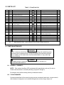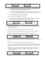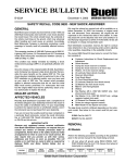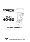
1
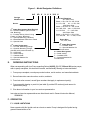
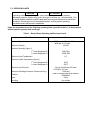
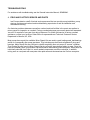
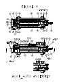
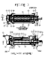
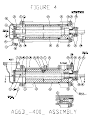
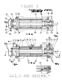
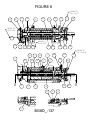
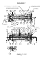
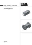
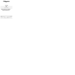
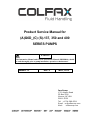
Product Service Manual for
(A)G6D_(C) (S)-137, 350 and 400
SERIES PUMPS
WARNING
This Instruction Manual and General Instructions Manual (SRM00046), should
be read thoroughly prior to pump installation, operation or maintenance.
SRM00113
Rev. 0
MAY, 2012
Imo Pump
1710 Airport Road
PO Box 5020
Monroe, NC USA
28111.5020
Tel: +1.704.289.6511
Email: [email protected]
Web:
colfaxcorp.com
READ THIS ENTIRE PAGE BEFORE PROCEEDING
FOR SAFETY OF PERSONNEL AND TO PREVENT DAMAGE TO EQUIPMENT, THE FOLLOWING
NOMENCLATURE HAS BEEN USED IN THIS MANUAL:
DANGER
Failure to observe precautions noted in this box can result in severe bodily injury
or loss of life.
WARNING
Failure to observe precautions noted in this box can cause injury to personnel by
accidental contact with equipment or liquids. Protection should be provided by
user to prevent accidental contact.
CAUTION
ATTENTION
Failure to observe precautions noted in this box can cause damage or failure of
equipment.
Non compliance of safety
instructions identified by
the following symbol
could affect safety for
persons:
Safety instructions where
electrical safety is
involved are identified by:
Safety instructions which
shall be considered for
reasons of safe operation
of pump and/or protection
of pump itself are marked
by the sign:
ATTENTION
ATTENTION
If operation of pump is critical to your business, we strongly recommend you keep
a spare pump or major repair kit in stock at all times. As a minimum, a minor
repair kit (o-rings, gaskets, shaft seal and bearings) should be kept in stock so
pump refurbishment after internal inspection can be accomplished.
CONTENTS
Safety and Table of Contents..................................................................................................... A
A. General Instructions .............................................................................................................. 1
B. Introduction ........................................................................................................................... 1
C. Description of Equipment ...................................................................................................... 1
D. Pump Model Identification ..................................................................................................... 2
E. Ordering Instructions ............................................................................................................. 2
F. Operation ............................................................................................................................. 3
G. Parts List ............................................................................................................................... 4
H. Pump Maintenance ............................................................................................................... 4
I. Troubleshooting .................................................................................................................. 10
J. Field and Factory Service and Parts ................................................................................... 10
K. Assembly Drawings ............................................................................................................ 11
L. Mechanical Seal Drawings .................................................................................................. 14
A
A. GENERAL INSTRUCTIONS
The instructions found herein cover the disassembly, assembly and parts identification of
(A)G6D_(C)-137, 350 and 400 series pumps
NOTE: Individual contracts may have specific provisions that vary from this manual. Should
any questions arise which may not be answered by these instructions, refer to the
General Instructions Manual, SRM00046, provided with your order. For further detailed
information and technical assistance please refer to Imo Pump, Technical/Customer
Service Department, at (704) 289-6511.
This manual cannot possibly cover every situation connected with the installation, operation, inspection,
and maintenance of equipment supplied. Every effort was made to prepare text of manual so that
engineering and design data is transformed into the most easily understood wording. Imo Pump must
assume personnel assigned to operate and maintain supplied equipment and apply this instruction
manual have sufficient technical knowledge and are experienced to apply sound safety and operational
practices which may not be otherwise covered by this manual.
In applications where equipment furnished by Imo Pump is to become part of processing machinery,
these instructions should be thoroughly reviewed to ensure proper fit of said equipment into overall
plant operational procedures.
WARNING
If installation, operation, and maintenance instructions are not correctly and strictly
followed and observed, injury to personnel or serious damage to pump could
result. Imo Pump cannot accept responsibility for unsatisfactory performance or
damage resulting from failure to comply with instructions.
B. INTRODUCTION
This instruction manual covers series (A)G6D_(C)-137, 350 and 400 Imo pumps. This series of pumps
has been designed for use in hydraulic, lubricating, seal, distillate, residual, fuel and crude oil
applications. The model and design construction of each pump can be identified by the designator code
on the pump nameplate. Definitions of model designators are identified in figure 1.
C. DESCRIPTION OF EQUIPMENT
(A)G6D_(C)-137, 350 and 400 series pumps are positive displacement, rotary screw pumps consisting
of precision bored housings which enclose a driven screw (power rotor) and intermeshing following
screws (idler rotors). These screws when rotating form a succession of closures or cavities. As they
rotate, fluid is moved axially from inlet port to outlet port in a continuous, uniform flow with minimum
fluid pulsation and pump noise.
D. PUMP MODEL IDENTIFICATION
This instruction manual covers Imo Series (A)G6D_(C)-137, 350 and 400 pumps. The model of each
pump is identified on pump nameplate. Refer to figure 1 and table 1 for instructional keys when using
this manual.
Figure 1 – Model Designator Definitions
AG
6D X
X X X 350 X
Design
Modification
Lead and Rotation
137 Rotor Size
Blank = 2D, CW D= 2D, CCW
A = 1D, CW
AL = 1.3D, CW
350 Rotor Size
Blank = 2D,CW D = 2D, CCW
G=1.8D, CW AN = 1.25D CW
J=1.5D CW
P = 1.6D CW
400 Rotor Size
Blank = 2D,CW D = 2D, CCW
P=1.6D,CW AJ = 1.35D, CCW
Series
1st Letter Designator (Seal Design)
B – Rubber Bellows (Buna Fitted
Std. Bearing)
H – Positive Drive (Viton O-ring
Fitted, Hi-Temp. Bearing)
K – Special Mounting, No Seal
N – Metal Bellows Seal Viton Fitted
X – Special Seal
2nd Letter Designator
C – Circular Mounting Flange
H – Special Mounting Flange
(Usually with previous letter K)
R – Axial Inlet
S – Steel Casing
T – Carbide Seat
X – Special Material Or
Construction
E.
Rotor Size
137, 350, 400
4th Letter Designator
T – Carbide Seat
X – Special Material Or
Construction
3rd Letter Designator
S – Steel casing
T – Carbide Seat
X – Special Material Or
Construction
ORDERING INSTRUCTIONS
When corresponding with Imo Pump regarding Series (A)G6D_(C)-137, 350 and 400 series pumps,
refer to pump nameplate, this instruction manual, and assembly drawing as instructed below:
1. From pump nameplate, record pump model number, serial number, and manufactured date.
2. Record instruction manual number, revision, and date.
3. From instruction manual, record figure numbers that apply to replacement part(s).
4. From assembly drawing or parts list (see table 2) provide IDP number(s) and names for
replacement part(s).
5. Give above information to your Imo service representative.
Imo sales and service representatives are listed herein and in General Instruction Manual,
SRM00046.
F. OPERATION
F.1 LIQUID LIMITATIONS
Never operate with thin liquids such as solvents or water. Pump is designed for liquids having
general characteristics of oil.
F.2 OPERATING LIMITS
CAUTION
ATTENTION
Operating conditions, such as speed, fluid viscosity, temperature, inlet pressure,
discharge pressure, filtration, duty cycle, drive type, mounting, etc., are interrelated. Due
to these variable conditions, specific application limits may be different from operational
limitations. Equipment must not be operated without verifying system operating
requirements are within pump’s capabilities.
Under no circumstances are the following operating limits (specified in table 1) to be exceeded
without specific approval from Imo Pump.
Table 1 – Normal Pump Operating and Structural Limits
Condition
Maximum Speed
Limit
2500 rpm for 350 and 400 sizes
4400 rpm for 137 size
32 SSU
Minimum Viscosity
Maximum Viscosity (figure 1)
1st Letter Designator B
st
1 Letter Designator H
Minimum Liquid Temperature
2500 SSU
15000 SSU
0°F
Maximum Liquid Temperature (figure 1)
1st Letter Designator B
st
1 Letter Designator H
Maximum Inlet Pressure
Maximum Discharge Pressure (Continuous Duty)
Filtration
Drive
Mounting
180°F
220°F
50 psig for 350 and 400 sizes
75 Psig for 137 size
1500 psig
Refer to General Instruction Manual,
SRM00046
Direct
Any attitude
G. PARTS LIST
Table 2 – Pump Parts List
IDP
1
2
4
QTY
1
1
16
6
7
8
9
21
22
1
1
2
2
2
1
23
24
25
26
27
28
2
1
1
2
6
2
29
31
35
38
42
1
1
2
2
2
X
XX
DESCRIPTION
Case
Inlet Head
Cap Screws (Qty 8 on size 400 Cface and all size 137)
Pin Stop
Fastener Seal
Housing Snap Rings
Cover Gasket or O-rings
Suction Idlers
Balance Piston Housing (Not On
C-Face Pumps)
Cups
Discharge Housing
Mechanical Seal
Housing Tube
Thrust Tube O-Rings
Housing O-Ring
KIT
X
XX
X
XX
XX
XX
XX
X
X
X
IDP
43
46
47
QTY
2
1
2
DESCRIPTION
Bearing Retainer
Inboard Cover
Bearing Retainer Hex Bolts
48
49
63
67
68
69
1
1
1
2
1
1
Seal Seat Adapter
Ball Bearing
Power Rotor
Pipe Plug
Tube Fitting (Not 137)
Pipe Nipple (Not 137)
70
71
73
74
83
86
1
1
1
1
1
1
Tubing Fitting
Seal Pipe
Inlet Housing
Pipe Fitting
Seal Gasket
Balance Piston
(C-face Pumps Only)
Hex Nuts (400 size C-face only)
Oil Balance Tube
Thrust Plate Spacer
Thrust Plate Hex Bolt
KIT
XX
X
XX
XX
X
X
Thrust Plate
XX
95
8
Key
100
1
Discharge Idlers
XX
101
2
Seal Spacer (Not 137 Size)
102
2
Bearing Retaining Ring
X
= Minor Repair Kit Items.
= Major Repair Kit Items. (Items marked (X) are included in Major Repair Kit.)
H. PUMP MAINTENANCE
WARNING
Failure to observe precautions while installing, inspecting and maintaining pump
can cause injury to personnel from accidental handling of liquids that may harm
skin or clothing, or fire hazard risks from flammable liquids, or injury from high
pressure fluid jets.
DANGER
BEFORE working on equipment, make sure all power to equipment is
disconnected and locked-out.
H.1 GENERAL COMMENTS
NOTE: Part number identifiers (IDP) contained within parenthesis, such as (9), refer to
circled numbers shown on assembly drawings (Figures 2 through 7).
De-energize driver before starting with any maintenance action.
H.2 TOOLS REQUIRED
Procedures described in this manual require common mechanics hand tools, a torque wrench,
dial indicators for alignment and a suitable lifting device such as slings, straps, etc.
H.3 Pump Disassembly Procedure
CAUTION
Fluid leakage from disassembly of pump may make floor slippery and cause
personal injury
Note: To service mechanical seal and ball bearing only, perform H.3, steps 1 thru 5
and H.4, Steps 14 through 17.
Determine pump model identification on pump nameplate to select applicable pump
assembly shown in Figures 2 thru 7. Refer to appropriate assembly for the following
instructions.
1. Close suction and discharge valves. Drain pump by removing drain plugs (67). Remove
seal tubing (71). Remove pump from driver, coupling and base plate. Remove coupling
hub and key (31).
2. Remove bearing retainer (43) from inboard cover (46) by removing bolts (47).
3. Remove assembled power rotor (63) from inboard cover (46). Removal of power rotor
(63) includes removal of snap rings (42), ball bearing (49), seal (25), seal seat adapter
(48) and spacer (38).
4. Disassemble power rotor (63) as follows (See Figure 1 for seal drawings):
ROTATI NG RI NG
ROTATI NG RI NG
DRI V E BAND
BEL L OWS
SPRI NG
SPRI NG
HOL DER
STATI ONARY SEAT
SEAT O- RI NG
L OCK PI N
SEAL SEAT
ADAPTER
SI NGL E SPRI NG RUBBER
BEL L OWS SEAL
FI GURE 1 -
CI RCL I P
DI SC
SPRI NG
RETAI NER
SET
SCREW
STATI ONARY SEAT
SEAT O- RI NG
L OCK PI N
SEAL SEAT
ADAPTER
MUL TI - SPRI NG SEAL
SEAL DRAWI NGS
a.
Using a flat nosed tool, such as a screw driver, remove snap rings (42) from groove
in power rotor (63).
b.
Sealed ball bearing (49) is assembled to power rotor (63) with light press fit. Ball
bearing (49) may be removed by using bearing puller or vertical arbor press. When
using press, place two pieces of key stock through openings of mechanical seal seat
adapter (48) underneath ball bearing (49) on both sides of power rotor shaft. Key
stock should be long enough to support power rotor (63) as it is placed in press.
Position press ram against power rotor (63) coupling end face. Gently press power
rotor (63) through ball bearing (49)
CAUTION
ATTENTION
Ensure power rotor (63) does not fall to floor once ball bearing (49) is off of its diameter
c.
Remove seal seat adapter (48) with stationary seal seat. Remove stationary seat
with O-ring from seal seat adapter (48). Discard O-ring.
d.
If seal is multi-spring type, disengage set screw and remove rotating seal seat. If seal
is a single spring rubber bellows type, remove it from shaft with a rotating motion.
e.
Remove spacer (38) from shaft where applicable.
5. Remove gasket (83) from inboard end cover (46).
6. Remove inboard cover (46) by removing bolts (4) or nuts (93) if pump is 400 size and
remove gasket (9) or, if pump is a C-face mount type, O-ring (28).
CAUTION
ATTENTION
If pump is size 400, C-face model, be sure not to damage studs in case (1) when
removing inboard cover (46)
7. Remove inlet head (2) from case (1) by removing bolts (4). Remove and discard gasket
(9) from inlet head (2).
8. Remove thrust plate (29) and spacers (101) by removing bolts (102).
9. Remove seal return tube (100) with O-rings (27). Remove and discard O-rings (27).
10. Remove cups (23) from idlers (21) and idlers (21, 35) from housings (73, 24).
CAUTION
ATTENTION
Do not permit idlers (21, 35) to drop as they emerge from housing (2).
11. Remove snap rings (8) from case (1). Remove pin stop (6) with fastener seal (7) from case
(1)
12. If pump is a C-face model skip to step 14, if not proceed to next step.
13. Remove balance piston housing (22) by pushing it out through the discharge end of the
case (1) with the housings (73, 24). Remove and discard balance piston housing O-ring
(28).
14. Remove housings (73, 24) by pushing them out through discharge end of the case (1).
Remove and discard housing O-ring (28). Remove tubes (26) and O-rings (27) from
housings (24 or 73).
CAUTION
ATTENTION
Do not permit housings (73, 24) to drop as they are removed from pump.
H4. Pump Reassembly Procedure:
Note: Prior to reassembly, all parts should be cleaned and inspected for nicks and burrs.
Replace all worn and damaged parts. Imo pump recommends replacement of ball bearing
(49), mechanical seal (25), gaskets (9, 83) and O-rings (28) when these parts are disturbed
from their original installed position. All parts should be coated with light lubricating oil to
assist in assembly.
1. Install O-ring (28) in groove in housing (24). Install O-rings (27) in grooves in tube (26) and
install tube (26) in housing (24) on opposite side as O-ring (28).
2. Install housing (24), O-ring end first, in pump case (1) from suction end until stop pin (6)
slot is properly aligned. Install stop pin (6) with fastener seal (7) in case (1).
3. Install housing (73) in pump case (1) with the end that has the two drilled and tapped holes
facing the inlet end of the pump. Be sure that tube (26) in housing (24) mates to hole in
housing (73).
4. Install snap rings (8) in case (1).
5. If pump is C-face version (Figure 3), proceed to next step, otherwise skip to step 11.
6. Remove balance piston bushing (86) from inboard cover (46) by heating it to loosen
loctite. Be sure to remove all traces of the old loctite before installing new bushing.
7. Clean and dry inboard cover (46) and balance piston bushing (86) mating surfaces with
solvent. Wipe Loctite “T747” Primer or equivalent onto the mating surfaces of bushing
(86) and inboard cover (46). Allow 1 to 5 minutes until primer is visibly dry. Apply Locitite
609 or equivalent to bushing (86) and inboard cover (46) mating surfaces. Assemble
bushing (86) into inboard cover (46). Allow 10 minutes to dry before proceeding with
assembly.
8. Install O-ring (28) on inboard cover. Install O-rings (27) on tube (26) and tube (26) in
inboard cover (46).
9. Install inboard cover (46) onto studs in discharge port side of case (1) using hex nuts (95).
Ensure seal vent (70) is facing up and pin (26) in inboard cover (46) mates with hole in
housing (24) Torque bolts (95) to value on appropriate assembly drawing.
10. Skip to step 14
11. Install O-ring (28) on balance piston housing (22). Install O-ring (27) on tube (26) and tube
(26) in balance piston housing (22).
12. Install balance piston housing (22) in case (1) lining up tube (26) in balance piston housing
(22) with hole in rotor housing (24). Install gasket (9) on inboard cover (46)
13. Install inboard cover (46) into discharge port side of case (1) using bolts (4). Ensure seal
vent (70) is facing up. Torque bolts (4) to value on appropriate assembly drawing
14. Assemble power rotor (63) and mechanical seal (25) as follows (See Figure 1 for seal
drawings):
a. Assemble spacer (38) onto shaft (63) where applicable.
b. If seal is a single spring rubber bellows type, apply light coat of system fluid to inside
diameter of bellows and slide mechanical seal rotating assembly on power rotor (63)
until it seats against the shoulder of seal spacer (38). Wipe seal face with isopropyl
alcohol and a lint free rag.
c. If seal is a multi-spring seal, coat O-ring inside of rotating seat with system fluid and
slide mechanical seal rotating assembly on power rotor (63) until it seats against the
shoulder of seal spacer (38). Tighten rotating seat set screw. Wipe seal face with
isopropyl alcohol and a lint free rag.
d. Install O-ring in groove of mechanical seal stationary seat. Install seat including O-ring
in seal seat adapter (48) ensuring that groove in back of stationary seat mates to
spring pin in seal seat adapter (48). Clean seal face with isopropyl alcohol and a lint
free rag. Put small amount of clean system fluid or light oil on seal running face.
Install stationary seat running face against rotating seat face.
e. Install inner snap ring (42) in groove of power rotor (63).
f.
Press bearing (49) on power rotor (63), using an installation sleeve by pressing only on
inner race until it is located next to inner snap ring (42).
g. Install outer snap ring (42) in groove of power rotor (63).
15. Install gasket (83) in seal bore of inboard cover (46).
16. Install assembled power rotor (63) in pump, centering all parts as they enter inboard cover
(46). Align one of openings in spacer (48) over drain in inboard cover (46).
17. Install bearing retainer (43) on inboard cover (46) using bolts (47). Torque bolts (47) to
value on appropriate assembly drawing.
18. Install idlers (35 and then 21) into housings (24, 73) by meshing threads with power rotor
thread
19. Install cups (23) on idlers (21).
20. Install bolts (102) in thrust plate (29) and spacers (101) on bolts (102).
21. Install O-rings (27) on tube (100) and tube (100) into housing (73).
22. Install thrust plate assembly including thrust plate (29), bolts (102) and spacer (101) on
housing (73). Be sure seal return hole in thrust plate (29) mates to tube (100) in housing
(73) Torque bolts (102) to value on appropriate assembly drawing.
23. Install gasket (9) on inlet head (2), and install inlet head (2) on case (1) using hex bolts (4).
Torque bolts (4) to value on appropriate assembly drawing
NOTE: Inlet head (2) can be rotated and repositioned in 90 degree increments to suit
suction piping. To change inlet position remove bolts (4) and rotate inlet head to
desired position. Install bolts (4) and torque to proper values indicated on
assembly drawing.
24. Install coupling hub key (16). Install and align pump and driver as specified in General
Instruction Manual, SRM00046.
TROUBLESHOOTING
For assistance with troubleshooting see the General Instruction Manual, SRM00046.
J. FIELD AND FACTORY SERVICE AND PARTS
Imo Pump maintains a staff of trained service personnel that can provide pump installation, pump
start-up, maintenance/overhaul and troubleshooting supervision as well as installation and
maintenance training.
Our factories provide maintenance as well as overhaul and test facilities in the event user prefers to
return pumps for inspection or overhaul. Factory-overhauled pumps are normally tested and warranted
“as-new” for a period of one year from date of shipment. For either field service or factory overhaul
assistance, contact your local Imo Sales Office or representative at Technical/ Customer Service
Department in Monroe, NC, USA.
Most pumps have repair kits available. Minor Repair Kits are used to repair leaking seals, bad bearings
and/or for re-assembly after pump tear-down. They include pump shaft seals all gaskets/O-rings and
bearings. Major Repair Kits are sufficient to rebuild completely worn-out pumps to “as-new” condition.
They include all parts found in Minor Repair Kits plus all major internal parts subject to wear. Since kits
have all necessary parts, kit purchase is preferred rather than selecting individual parts. When parts are
individually selected from Parts List, some needed components are often overlooked. In addition,
mixing worn or used parts with new parts risks rapid wear and shortened service life from new parts.
FIGURE 6
TORQUE TO
50 u 5 LB-FT
23
67
29
9
35
21
28
22
4
9
48
TORQUE TO
75 u 5 LB-IN
102
TORQUE TO
50 u 5 LB-FT
74
71
23
21
4
35
25
28
42
31
TORQUE TO
100 u 10 LB-IN
100
2
27
27
27
67
47
43
OUTLET
8
73
49
24
27
101
70
27
6
INLET
B
83
46
7
26
1
26
BG6D_-137
27
63
B
FIGURE 7
SLOT IN BEARING SPACER TO
LINE UP WITH HOLE IN COVER
INSTALL BUSHING IDP 86 TO END COVER IDP 46
USING LOCTITE ES 2.3.3-D1 PER ES 3.14.1
IDLER STOP LUGS TO BE LOCATED
ON HORIZONTAL CENTERLINES AS SHOWN
67
23
9
TORQUE TO
50 u 5 LB-FT
35
21
93
48
28
86
29
102
74
TORQUE TO
75 u 5 LB-IN
TORQUE TO
50 u 5 LB-FT
23
1
27
6
26
67
101
7
42
27
27
31
TORQUE TO
100 u 10 LB-IN
83
46
43
27
INLET
B
25
28
70
100
2
35
4
21
47
OUTLET
8
73
24
G6D_C-137
49
63
B
Imo Pump
1710 Airport Road
PO Box 5020
Monroe, NC USA
28111.5020
Tel: +1.704.289.6511
Toll: +1.877.853.7867
Email: [email protected]
Web:
colfaxcorp.com
© 2012 Colfax Fluid Handling all rights reserved.