Download Harware Service Manual
Transcript
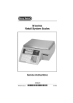
ETICA 2300
Hardware Service manual
© Mettler-Toledo EPEC SAS
EPEC Nr.29230032_E Printed in Germany 06/06
Hardware Service manual – MT EPEC
Etica2300 weighing-labelling unit
Table of Contents
INTRODUCTION .............................................................................................................................................................................................. 4
1.GENERAL CHARACTERISTICS .................................................................................................................................................................. 5
1.1 TECHNICAL CHARACTERISTICS .................................................................................................................................................................5
1.2 METROLOGICAL CHARACTERISTICS...........................................................................................................................................................6
1.3 TECHNICAL CHARACTERISTICS OF WEIGHING BASES..................................................................................................................................6
1.4 E TICA2300 WORKING KEYPAD ................................................................................................................................................................7
2. INSTALLATION .........................................................................................................................................................................................11
3. EXPLODED VIEWS...................................................................................................................................................................................13
3.1 GENERAL VIEW OF THE E TICA2300 (29268560) ...............................................................................................................................13
3.2 GENERAL VIEW OF THE E TICA2300 (29268560 CONTINUED ) ............................................................................................................13
3.3 COMPLETE LIST OF ETICA2300 COMPONENTS.......................................................................................................................................15
3.4 E QUIPPED MOTHERBOARD (29223106) .............................................................................................................................................16
3.5 BOARD SUPPORT PLATE (29268584) ASSEMBLY ................................................................................................................................18
3.6 PRINTER / REWINDER PLATE (29268585*) SUB-ASSEMBLY ................................................................................................................20
3.7 MONOCHROME DISPLAY PLATE (29268586) ......................................................................................................................................22
3.8 E QUIPPED COLOUR DISPLAY PLATE (29268590).................................................................................................................................24
3.9 COLOUR DISPLAY PLATE (29268589 CONTINUED )..............................................................................................................................26
3.10 ADJUSTABLE FOOT 110 MM (29268587**) ...................................................................................................................................28
3.11 PAPER ACCESS DOOR (29268588) .................................................................................................................................................30
3.12 FIXED FOOT (29268592**).............................................................................................................................................................32
4. DNA AND WP27 LOADCELL SEALING.................................................................................................................................................35
4.1 WP27DS BASE .................................................................................................................................................................................36
4.2. IDNET BASE ......................................................................................................................................................................................39
IDNET SEALING ...........................................................................................................................................................................................40
5. ELECTRONIC BLOCK DIAGRAM ............................................................................................................................................................41
6. DIAGNOSTIC AND FAULT ANALYSIS....................................................................................................................................................43
6.1 NOTHING HAPPENS ON START-UP...........................................................................................................................................................44
6.2 NO WEIGHING MANAGEMENT: ................................................................................................................................................................45
6.3 PRINTING PROBLEMS.............................................................................................................................................................................46
7. REPLACEMENTS ......................................................................................................................................................................................47
7.1 REPLACING THE PCB UBASE (22005434) BOARD............................................................................................................................48
7.2 REPLACING THE POWER SUPPLY BOARD (22006145) .........................................................................................................................49
7.3 REPLACING THE PCB-ULP3-C BOARD (22005076)..........................................................................................................................50
7.4 REPLACING THE SCREEN AND CONVERTER BOARD/KEYPAD BOARD ASSEMBLY ..........................................................................................51
7.5 REPLACING THE THERMAL HEAD (10) (29268560) ...........................................................................................................................52
8. DESCRIPTION, TEST POINTS AND SETTINGS ....................................................................................................................................53
8.1 DESCRIPTION OF THE PSU-0053-03 POWER SUPPLY BOARD (22006145).......................................................................................53
8.1.1. Electrical characteristics:......................................................................................................................................................53
8.1.2 Wiring diagram and test points............................................................................................................................................54
8.1.3 Wiring diagram.......................................................................................................................................................................55
8.2 DESCRIPTION OF THE PCB-UBASE ME 22005434 CPU BOARD .......................................................................................................56
8.2.1 Block diagram of the PCB-UBASE ES-22005434 CPU board..........................................................................................58
8.2.2 PCB-UBASE ME-22005434 diagram..................................................................................................................................59
8.3 DESCRIPTION OF THE PCB-EXT-MGX266 BOARD (22006755) .......................................................................................................60
8.3.1 Layout of the PCB ETX-MGX266 board (22006755).....................................................................................................62
EPEC Nr.29230032_E
Page 2/97
Hardware Service manual – MT EPEC
Etica2300 weighing-labelling unit
8.4 DESCRIPTION OF THE MONOCHROME LCD SCREEN HLM 8620 (22006050) ....................................................................................63
8.4.1 Block diagram.........................................................................................................................................................................63
8.4.2 Colour screen LQ057Q3DC02 ..............................................................................................................................................64
8.5 DESCRIPTION OF THE PCB-ULCDO ES 22005402A CONVERTER BOARD ...........................................................................................65
8.5.1 Diagram of the PCB-ULCDO ES 22005402 A board.........................................................................................................65
8.6 DESCRIPTION OF THE PCB-PRINTER BOARD (22005076) ................................................................................................................66
8.6.1 Block diagram of the PCB-printer board (29223191) .....................................................................................................67
8.6.2 Layout, connectors and LEDs: ..............................................................................................................................................68
8.7 RS 232/485 PC104 COMMUNICATION EXPANSION BOARD (29223232) ........................................................................................69
8.7.1 Layout diagram.......................................................................................................................................................................69
8.7.2 Configuration of the PC 104 board......................................................................................................................................69
8.7.3 PC 104 board serial port tests..............................................................................................................................................70
8.7.4 Example of RS 485 communication test.............................................................................................................................70
8.8 DESCRIPTION OF THE TD27 BOARD (DIAGRAM NO. 29223021/222)................................................................................................71
9. CONNECTION CABLES ...........................................................................................................................................................................73
9.1 UBASE / KEYPAD CABLE (29223101*) ............................................................................................................................................73
9.2 POWER SUPPLY / PRINTER BOARD CABLE (29223103*)...................................................................................................................74
9.3 KHEOPS NETWORK CABLE (29223109)............................................................................................................................................75
9.4 CROSSED E THERNET 10/100/1000BASE -T CABLE (29223215)......................................................................................................76
10. ETICA2300 SOFTWARE CONFIGURATION........................................................................................................................................77
10.1 BIOS-FLASH........................................................................................................................................................................................77
11. LABEL ADJUSTMENT............................................................................................................................................................................78
11.1 LABEL ADJUSTMENT (LABEL PRE -DETERMINATION FUNCTION)..............................................................................................................78
11.1.1 Adjustment of the label detection cell................................................................................................................................78
12. CALIBRATION PROCEDURE ................................................................................................................................................................83
12.1 WP 27DS BASE ..............................................................................................................................................................................83
12.1.1 Information menu .................................................................................................................................................................84
12.1.2 Filtering menu.......................................................................................................................................................................84
12.1.3 Calibration menu:.................................................................................................................................................................85
12.2 IDNET BASE .......................................................................................................................................................................................86
12.1.1 Information menu .................................................................................................................................................................87
12.1.2 Filtering menu.......................................................................................................................................................................87
12.1.3 Calibration menu:.................................................................................................................................................................88
12.2.4 Scale Parameters menu:.....................................................................................................................................................90
13. ERROR MESSAGES...............................................................................................................................................................................92
14. CHANGING THE PAPER ROLL AND MAINTENANCE........................................................................................................................93
14.1 CHANGING THE LABEL ROLLS...............................................................................................................................................................93
14.2 MAINTENANCE / CLEANING .................................................................................................................................................................94
15. APPENDICES.........................................................................................................................................................................................95
15.1 APPENDIX 1: LIST OF SPARE PARTS* .......................................................................................................................................95
15.2 APPENDIX 2: LIST OF ACCESSORIES** ....................................................................................................................................96
EPEC Nr.29230032_E
Page 3/97
Hardware Service manual – MT EPEC
Etica2300 weighing-labelling unit
INTRODUCTION
This document is intended for After Sales Support technicians working on all normal versions of Etica 2300.
This manual gives details of the product codes of the parts and the make up of the sub-assemblies in the Etica 2300 group.
It also describes the maintenance tasks most frequently carried out on this weighing-labelling unit.
The official summary list of spare parts and sub-assemblies required for these maintenance operations is given page 97.
These spare parts and sub-assemblies are available as standard from MT-LOG. You can order them by EDI, giving their respective
MTCIMF codes.
i
Parts written in bold underlined together with an asterisk (*), in the various exploded views shown in this manual
are available as "spare parts" from MT-LOG.
Parts written in bold double underlined together with a double asterisk (**), in the various exploded views are
available as "accessories" from MTA.
For any comments or corrections specifically concerning the content of this manual, contact directly the MT-EPEC Technical Support
team, responsible for any updates:
- Santy Savatxath (French, English): + 33 6 08 27 92 84 / [email protected]
- Bruno Goudard (French, English, German): + 33 6 81 685 305 / [email protected]
EPEC Nr.29230032_E
Page 4/97
Hardware Service manual – MT EPEC
Etica2300 weighing-labelling unit
1.GENERAL CHARACTERISTICS
The Etica2300 weighing-labelling unit is a multi-protocol weight-price indicator/calculator, equipped with a thermal label
printer. It has European certification (Directives 90/384/CEE and 93/68/CEE) as a non automatic electronic weighing instrument.
The Etica2300 is dedicated to weighing-labelling applications in commercial or industrial environments and especially to preweighing of fresh products. It cannot be used for direct sale to the public.
The Etica2300 weighing-labelling unit can be used alone, as a simple label printer, or in combination with:
-the D, M and K series IDNET weighing bases (Albstadt design).
-the WP27DS multi-interval top of the range Prepack base (MT EPEC design)
-the 8270 multi-range standard Prepack base (MTWR design)
1.1 Technical characteristics
INPUT
230 V, 50-60 Hz 1.6 A / Fuse: T3.15 A/250 V
OUTPUT
+5V /4.0A and +12V /1.0A and +24V / 1.2A
OPERATING TEMPERATURE RANGE
-10°C to +40°C / 5% to 85 % relative humidity (no condensation)
SAFETY
In compliance with the Low Voltage Directive; protected against short circuits.
The Etica2300 model weighing-labelling unit is equipped with seven communication interfaces (with the optional PC104
communication board):
-COM0 RS232 (Bar code reader)
-COM1 RS232 (Weighing base)
-COM2 RS232
-COM3 RS485
-RJ 45 Ethernet 10/100 Mbs
-USB1 and USB2. (optional)
-RJ11 Wrapping unit connection
EPEC Nr.29230032_E
Page 5/97
Hardware Service manual – MT EPEC
Etica2300 weighing-labelling unit
1.2 Metrological characteristics
The Etica2300 labelling unit can be connected to various weighing bases. (WP27DS, IDNET, etc.)
The metrological characteristics are as follows:
Precision
Resolution
Weighing cell power supply
Maximum signal for the dead load
Minimum signal for the dead load
Sensitivity
Minimum voltage of the measurement range
Maximum voltage of the measurement range
Minimum impedance for the weighing cell
Maximum impedance for the weighing cell
Max. wire length
Unit price interval value
Maximum unit price
Price interval
Max. price
Class III (IPFNA or IPFA)
=3000 points
5.4 Volts to 10 Volts
3mV
0.5 mV
1 µV/E.v
0.5 mV
13.5 mV
100Ω
1000Ω
2 m (4 wires) for RLC=350 Ω min.
du = 0.01 €kg
9999,99€
dp = 0.01 €
999 999,99€
1.3 Technical characteristics of weighing bases
The weighing bases are:
WP27DS base
SW1-5
OFF
ON
OFF
ON
SW1-6
OFF
OFF
ON
ON
SW1-7
OFF
OFF
OFF
OFF
RANGE
Free range
3kg/2g
6kg/2g
4kg/2g
12kg/5g
12kg/5g
8kg/5g
MULTI
INTERVAL
IDNET base
DNA
Scale
Capacity
6
6
12
30
15
15
30
accuracy e1 = Vmin
units
kg
kg
kg
lb
kg
kg
kg
3000
2x3000
6000
3 000
3000
2x3000
6000
EPEC Nr.29230032_E
2
1
2
0.01
5
2
5
Load cell
ZTC
Plc Capacity
spec
units
kg
ppm LC cap/C
g
0.8
20
16.0
g
0.8
10
16.0
g
0.8
20
16.0
lb
0.7
50
12.7
g
0.8
50
16.0
g
0.8
20
16.0
g
0.8
50
16.0
Signal
5 V EXC
uV/e
1.00
1.00
1.00
0.91
1.00
1.25
1.00
Page 6/97
Hardware Service manual – MT EPEC
Etica2300 weighing-labelling unit
1.4 Etica2300 working keypad
The keypad consists of 59 keys.
Description of keys:
EPEC Nr.29230032_E
Ø
17 function keys dynamically allocated on screen
Ø
TABULATION key
Ø
RETURN TO PREVIOUS MENU key
Page 7/97
Hardware Service manual – MT EPEC
Ø
HELP key or letter "A".
Ø
MODE key or letter "B".
Ø
Reference code entry key or letter "C"
Ø
RESET key or letter "H"
Ø
MANUAL TARE key or letter "I".
Ø
SEMI-AUTOMATIC TARE key or letter "J"
Ø
KEYPAD ACCESS key (special characters) or letter "O"
Ø
LABEL MENU key or letter "P"
Ø
TOTALLING key, log or letter "Q"
Ø
Key not used or letter "V"
Ø
Key not used or letter "W"
Ø
EXTRA FUNCTIONS key or letter "X"
Ø
EPEC Nr.29230032_E
Etica2300 weighing-labelling unit
Numeric keys and correction key, letters " D; E; F; K; L; M;
R; S; T; Y; Z"
Page 8/97
Hardware Service manual – MT EPEC
Ø
MULTIPLICATION key or letter "G"
Ø
SUBTRACTION key or letter "N"
Ø
ADDITION key or letter "U"
Ø
VALIDATION key
Ø
EPEC Nr.29230032_E
Etica2300 weighing-labelling unit
Movement key
Ø
CANCEL key
Ø
PRINT key
Ø
BACK SPACE key
Ø
SHIFT KEY (press another key simultaneously to enter the corresponding alphabetic
letter)
Ø
CAPS LOCK key
Ø
ALT key
Ø
SPACE key
Page 9/97
Hardware Service manual – MT EPEC
Etica2300 weighing-labelling unit
2. INSTALLATION
Step 1- Place the weighing base and your assembly on a flat, stable support
Step 2 – Adjust the feet of the weighing base, checking the bubble level
Step 3- Check the connections between the weighing base and the Etica2300
Step 4- Make sure that that there is a label roll.
Step 5- Plug in your weighing/labelling unit to a 230 V mains power outlet
Step 6- Press the ON / OFF switch to ON
Step 7- The unit loads the data and displays the working screen.
i
You are recommended to program your unit fully before entering operating mode.
EPEC Nr.29230032_E
Page 11/97
Hardware Service manual – MT EPEC
Etica2300 weighing-labelling unit
3. EXPLODED VIEWS
3.1 General view of the Etica2300 (29268560)
3.2 General view of the Etica2300 (29268560 continued)
EPEC Nr.29230032_E
Page 13/97
Hardware Service manual – MT EPEC
EPEC Nr.29230032_E
Etica2300 weighing-labelling unit
Page 14/97
Hardware Service manual – MT EPEC
Etica2300 weighing-labelling unit
3.3 Complete list of Etica2300 components
No.
Qty
Designation
MTCIMF reference
1
2
SCREW FHC M3X10 STAINLESS STEEL
29006979
2
2
SUBD CONNECTOR STRUT
00209834
3*
4*
1
1
CICA COM CPU WEIGHT BASE
SOCKETS / CPU CABLE
29223081
29223102
5
1
CABLE SWITCH
29223105
6
1
BODY STRUCTURE
29268580
7
1
EQUIPPED BOARD SUPPORT PLATE
29268584
8*
9
1
1
PRINTER / REWINDER PLATE
EQUIPPED DISPLAY PLATE
29268585
29268586
10*
1
THERMAL HEAD KF2003 GK4
22006052
11
1
EQUIPPED PAPER ACCESS DOOR
29268588
12
1
ELECTRONIC ACCESS DOOR
29268608
13
14
1
4
SOCKET COVER PLATE
SCREW F TORX M4X6 STAINLESS STEEL
29268610
22008388
15
1
SERRATED LOCKWASHER SIZE 5 STAINLESS STEEL
29210038
16
1
LOCKING WASHER D6
29015744
17
5
SCREW TBHC M3X6 STAINLESS STEEL
29015868
18
19
1
1
ROLL SUPPORT MANDREL PIN
ROLL SUPPORT D=76
29016617
29016752
20*
1
CABLE CPU COM WEIGHT
29220040
21
1
STRUT
29268612
22
1
UNICOR MOTHERBOARD
29223106
23*
24
1
5
CONNECTOR BOARD
SCREW TBHC M4X8 STAINLESS STEEL
22005437
29016392
25
1
SCREW TBHC M5X12 STAINLESS STEEL
29016400
26*
1
KEYPAD / CPU CABLE
29223101
27
2
FRICTION WASHER
29015503
28
29
8
1
TORX SCREW M4x8
SOCKET COVER
22001568
29268617
30
2
SCREW C M3x4 STAINLESS STEEL
00076110
32
6
SERRATED LOCKWASHER SIZE 4
00206235
33
1
EARTH CABLE
29223104
34
35
1
1
ROTATION BRACKET
MAINS CORD
29268607
00505784
36
1
DISC MAGNET m1219-4
29210033
37*
1
DISPLAY / CPU CABLE
29220038
38*
2
TORX SCREW M3x4
22006134
40
41
1
1
SOCKET COVER
RUBBER FOOT
00206286
00200068
43
1
FLAT CABLE FERRITE
29220048
44
0,02
DOUBLE SIDED TAPE width 12 mm
29014225
45
1
SEALING PLATE
29268599
46
47
1
1
SEALING STICKER
IDENTIFICATION PLATE
00203808
22006759
48
1
SCREW FHC M4x10 STEEL
22003002
EPEC Nr.29230032_E
Page 15/97
Hardware Service manual – MT EPEC
Etica2300 weighing-labelling unit
3.4 Equipped motherboard (29223106)
EPEC Nr.29230032_E
Page 16/97
Hardware Service manual – MT EPEC
Etica2300 weighing-labelling unit
List of motherboard components
No.
Qty
Designation
MTCIMF reference
1*
1
PCU-UBASE CPU BOARD
22005434
2*
1
COMPACT FLASH 32 MB
22006190
3*
1
RAM / SIMM 64 MB BOARD
22007263
4*
1
ETX GEODE 266 EXPANSION BOARD
22007444
EPEC Nr.29230032_E
Page 17/97
Hardware Service manual – MT EPEC
Etica2300 weighing-labelling unit
3.5 Board support plate (29268584) assembly
EPEC Nr.29230032_E
Page 18/97
Hardware Service manual – MT EPEC
Etica2300 weighing-labelling unit
List of support plate assembly spare parts
No.
Qty
Designation
MTCIMF reference
1
2
WASHER D4 STAINLESS STEEL
00206128
2
1
BLANK EPROM
00506241
2
1
PROGRAM
22007442
3
2
TORX SCREW M4x8
22001568
4*
1
PRINTER BOARD
22005076
5*
1
POWER SUPPLY BOARD
22006145
6*
1
CPU / PRINTER CABLE
22006215
7*
1
POWER SUPPLY / CPU CABLE
22006218
8
2
SCREW CHC M4x16 STAINLESS STEEL
29014197
9
6
SERIES 100 2 CIRCUIT SUPPORT
29210021
10
1
CABLE TIE D10
29210040
11*
1
POWER SUPPLY / PRINTER CABLE
29223103
12
1
BOARD SUPPORT PLATE
29268609
13
1
POWER SUPPLY BOARD HEAT SINK
29268614
14
1
POWER SUPPLY BOARD SCREENING PLATE
29268615
15
1
JUMPER PITCH 2.54
29024888
EPEC Nr.29230032_E
Page 19/97
Hardware Service manual – MT EPEC
Etica2300 weighing-labelling unit
3.6 Printer / rewinder plate (29268585*) sub-assembly
EPEC Nr.29230032_E
Page 20/97
Hardware Service manual – MT EPEC
Etica2300 weighing-labelling unit
List of printer / rewinder plate (29268585*) sub-assembly parts
No.
Qty
Designation
MTCIMF reference
1
2
CABLE TIE
00202076
2
8
CIRCLIP D =2.5
00206104
3
1
PRINTER MOTOR CLAMP
00209043
4
1
LEVER GUARD
00209829
5
15
TORX SCREW M4x8
22001568
6
1
HEAD SUPPORT SPRING
22006053
7
1
HEAD PIN
22006055
8*
1
ROLL
22006057
9
2
REWINDER PINION
22006058
10
3
PINION 19/55
22006059
11*
1
PAPER CELL
22006060
12*
1
PAPER MOTOR
22006061
13*
1
LABEL PRESENCE CELL
22006063
14*
1
REWINDER MOTOR
22006064
15
1
SLIDE BEARING
22006066
16
1
REAR PAPER GUIDE
22006067
17
1
FRONT PAPER GUIDE
22006068
18
1
PAPER GUIDE SETTING SCREW
22006069
19
6
ATTACHMENT PIN
22006070
20
1
ROLL SUPPORT PLATE
22006071
21
1
LABEL KNIFE
22006073
22
2
PINION 2 Z=55
22006074
23
1
HEAD SUPPORT LEVER
22006079
24
1
SLIDE BEARING
22006088
25
1
MOTOR GUARD
22006093
26
1
THERMAL HEAD SUPPORT
22006129
27
1
TORX SCREW M3x4
22006134
28
1
REWINDER
22006136
29
1
TILTING UNIT LEVER SUPPORT
22006273
30
1
TILTING UNIT SPRING
22009301
31
2
SCREW TFHC M3x16 STAINLESS STEEL
29210025
32
2
STRUT 3 X D5 X L10
29210034
33
1
PRINTER / HEAD RIBBON CABLE
29220039
34
1
PRINTER PLATE
29268581
35
1
CABLE PROTECTIVE PLATE
29268616
36
1
PRINTER HOUSING
29268620
EPEC Nr.29230032_E
Page 21/97
Hardware Service manual – MT EPEC
Etica2300 weighing-labelling unit
3.7 Monochrome display plate (29268586)
EPEC Nr.29230032_E
Page 22/97
Hardware Service manual – MT EPEC
Etica2300 weighing-labelling unit
List of monochrome display plate (29268586) sub-assembly parts
Qty
No.
Designation
MTCIMF reference
1
1
NUT HUM4 STAINLESS STEEL
00076498
2
1
WASHER 4.3x9x0.8 STAINLESS STEEL A4
00206128
3*
1
MONOCHROME DISPLAY CIRCUIT
22005401
4*
1
MONOCHROME DISPLAY HLM8620
22006050
5
9
TORX SCREW DIN7500 M3x4
22006134
6
3
SNAP CAP
29210024
7*
1
KEYPAD BOARD
29223091
8*
1
ASSEMBLED KEYPAD/PLATE
29268597
EPEC Nr.29230032_E
Page 23/97
Hardware Service manual – MT EPEC
Etica2300 weighing-labelling unit
3.8 Equipped colour display plate (29268590)
EPEC Nr.29230032_E
Page 24/97
Hardware Service manual – MT EPEC
Etica2300 weighing-labelling unit
List of equipped colour display plate (29268590) sub-assembly parts
No.
Qty
Designation
MTCIMF reference
1
1
ASSEMBLED KEYPAD/PLATE
29268597
2
1
WASHER 4 3X9X0 8 A4
00206128
3
1
NUT HUM4 STAINLESS STEEL
00076498
4
1
KEYPAD INTERFACE BOARD
29223091
5
3
SNAP CAP
22006134
6
5
SCREW CZXM3X4
22006134
7
1
AQ COLOUR DISP SUPP
29268589
8*
1
COLOUR TFT INTERFACE
29223211
9
4
TORX SCREW TBM3X8 STAINLESS STEEL
29210129
10
1
33 PIN RIBBON CABLE
29220062
EPEC Nr.29230032_E
Page 25/97
Hardware Service manual – MT EPEC
Etica2300 weighing-labelling unit
3.9 Colour display plate (29268589 continued)
EPEC Nr.29230032_E
Page 26/97
Hardware Service manual – MT EPEC
Etica2300 weighing-labelling unit
List of colour display plate sub-assembly parts (continued)
No.
Qty
Designation
MTCIMF reference
1
1
COLOUR DISP SUPP PLATE
29268629
2*
1
SHARP DISPLAY LQ057Q3DC02
29220058
3
4
TORX SCREW DIN 7500C M3X6 STAINLESS STEEL
29210131
EPEC Nr.29230032_E
Page 27/97
Hardware Service manual – MT EPEC
Etica2300 weighing-labelling unit
3.10 Adjustable foot 110 mm (29268587**)
EPEC Nr.29230032_E
Page 28/97
Hardware Service manual – MT EPEC
Etica2300 weighing-labelling unit
List of adjustable foot 110 mm (29268587**) sub-assembly parts
No.
Qty
Designation
MTCIMF reference
1
3
NUT HUM4 STAINLESS STEEL
00076498
2
1
SCREW H M8X12 STAINLESS STEEL
29210092
3
8
SERRATED LOCKWASHER SIZE 4
00206235
4
1
TORX SCREW M4x8 STAINLESS STEEL
29210098
5
2
PUSH-IN CLIP
29016303
6
2
CLAMP LEVER HANDLE
29210015
7
1
FLAT WASHER 4x25x1 STAINLESS STEEL
29210041
8
2
EARTH CABLE
29223104
9
4
GROMMET
29267915
10
1
FOOT
29268582
11
1
PIVOT PIN
29268605
12
1
ROTATION PIN SUPPORT
29268611
13
1
STAINLESS STEEL THREADED ROD M6
29268613
EPEC Nr.29230032_E
Page 29/97
Hardware Service manual – MT EPEC
Etica2300 weighing-labelling unit
3.11 Paper access door (29268588)
EPEC Nr.29230032_E
Page 30/97
Hardware Service manual – MT EPEC
Etica2300 weighing-labelling unit
List of paper access door (29268588) sub-assembly parts
No.
Qty
Designation
MTCIMF reference
1
1
SCREW TBHC M5X12 STAINLESS STEEL
29016400
2
1
BALL HANDLE
29210035
3
1
SERRATED LOCKWASHER SIZE 5 STAINLESS STEEL
29210038
4
1
PAPER ACCESS DOOR
29268583
EPEC Nr.29230032_E
Page 31/97
Hardware Service manual – MT EPEC
Etica2300 weighing-labelling unit
3.12 Fixed foot (29268592**)
EPEC Nr.29230032_E
Page 32/97
Hardware Service manual – MT EPEC
Etica2300 weighing-labelling unit
List of Fixed foot (29268592**) sub-assembly parts
No.
Qty
1
Designation
MTCIMF reference
2
SCREW H M8X12 STAINLESS STEEL
29210092
3
2
PUSH-IN CLIP
29016303
4
1
BOX ATTACHMENT PIN
29267373
5
4
GROMMET
29267915
6
1
FIXED FOOT
29268606
2
EPEC Nr.29230032_E
Page 33/97
Hardware Service manual – MT EPEC
Etica2300 weighing-labelling unit
4. DNA and WP27 Loadcell SEALING
EPEC Nr.29230032_E
Page 35/97
Hardware Service manual – MT EPEC
Etica2300 weighing-labelling unit
4.1 WP27DS BASE
EPEC Nr.29230032_E
Page 36/97
Hardware Service manual – MT EPEC
Etica2300 weighing-labelling unit
List of WP27DS base sub-assembly parts
No.
Qty
Designation
MTCIMF reference
1
1
EQUIPPED WP27 BASE TANK
29210092
2
1
WEIGHT BASE COVER
29267972
3
3
TORX SCREW M4X8 STAINLESS STEEL
29210098
4
1
SEALING PLATE
29267979
5
1
CELL CROSSBAR
29267978
6
1
SEALING STAMP
00203808
7
1
WP27 EQ PLATE SUPPORT
29267963
8
1
SCREW CHC M6X25 STAINLESS STEEL
29014192
9
1
WEIGHT BASE PLATE
29267977
10
1
SCREW FHC M4X8 STAINLESS STEEL
29015065
11*
1
BOX TD27
29267990
12*
1
SENSOR ACJ 6/2 15/5
29018309
EPEC Nr.29230032_E
Page 37/97
Hardware Service manual – MT EPEC
Etica2300 weighing-labelling unit
4.2. IDNET BASE
EPEC Nr.29230032_E
Page 39/97
Hardware Service manual – MT EPEC
Etica2300 weighing-labelling unit
IDNET sealing
Self-adhesive sticker
Self-destructive
Sealing screw
EPEC Nr.29230032_E
Page 40/97
Hardware Service manual – MT EPEC
Etica2300 weighing-labelling unit
5. ELECTRONIC BLOCK DIAGRAM
EPEC Nr.29230032_E
Page 41/97
Hardware Service manual – MT EPEC
Etica2300 weighing-labelling unit
6. DIAGNOSTIC AND FAULT ANALYSIS
This chapter helps you solve any problems you may encounter with the Etica2300 unit during installation or use.
Before you can use the Etica2300 unit, it must first start.
You will only be able to see whether the Etica2300 unit is operating correctly after it has started.
On start-up, all the components are supplied with electricity so that they can perform a series of test procedures before the
operating system is loaded.
Errors may occur during these procedures, preventing the unit from operating.
In this case, the most difficult part is the diagnostic: what is preventing the unit from starting?
The error can usually be corrected very simply if it has been diagnosed correctly.
Start with the Check-list below to check the main points. This will allow you to detect an error before any damage occurs.
There are two possible cases:
The unit does not come on at all:
Check-list
•
•
•
•
Check 1: Remove the power supply cable from the unit and check again that the mains CABLE and the fuse F1
6.3A/250V are correctly fitted.
Check 2: Is the jumper on connector X2 fitted between pins 1 and 2? (X2)
Check 3: Is the Compact Flash memory board locked in its connector? (ETX-MGX 266)
Check 4: Check all the ribbon cables including those of the power supply and the hard disk (if present)
(See flowcharts appended).
The unit comes on but nothing appears on screen:
Whenever you switch on the unit, LED D90 is permanently lit.
It indicates that the processor of the JUMPtec ETX CPU for PC embedded computer board is running the boot program
contained in the BIOS. This program sets the default parameters, it initialises all the components and puts all the components
in a particular mode.
If these
•
•
•
sequences are not carried out, LED D90 flashes three times per second:
Check the state of the JUMPtec ETX CPU for PC embedded computer board.
Reload the BIOS boot software on the Compact-Flash board or the hard disk.
Reinstall the system application.
EPEC Nr.29230032_E
Page 43/97
Hardware Service manual – MT EPEC
Etica2300 weighing-labelling unit
6.1 Nothing happens on start-up
When the Etica2300 is switched on nothing happens. The usual start-up message "Starting, please wait" is not displayed. No
LED lit,
Is the power supply faulty?
Yes
•
•
•
•
Check the 230 V power supply
Check its voltage
The fuse F1 6.3Amp
Change the power supply
•
Check the position with an
Ohmmeter
Check the motherboard power
supply and power supply lead
(change the mains lead)
No
Yes
Yes
•
No
•
Is the ETX JUMPtec board
defective?
•
Yes
No
•
Check that the ETX board is
inserted properly
Check the STX1 and STX4
support pins.
Is the Flash memory card
defective?
(Compact Flash card)
•
Yes
•
Check the Flash memory card
on its connector
Is the support in good
condition?
No
After switching on nothing happens
Are the power supply cables
causing a short circuit
Or break?
Short circuit between Neutral or
Phase of the mains and the
electrical ground.
•
•
•
Check the circuit-breaker
Reset the circuit-breaker
Are the drives connected to
ground?
No
Yes
Change the motherboard
PCB-BASE(2005434)
EPEC Nr.29230032_E
Page 44/97
Hardware Service manual – MT EPEC
Etica2300 weighing-labelling unit
6.2 No weighing management:
Yes
•
•
•
Check the power supply
Check its voltage
Change the power supply
•
•
Check the continuities
Change the weighing base
lead (29223166)
•
Check the connection of the
Load-cell connector (KU60)
Change the Ubase / weight
Communication lead
(29220040)
No
Is the power supply of the IDNET
board defective?
Yes
No
Is the connection cable with the
weighing bases at fault?
Is the communication part faulty?
Yes
No
•
Is the choice of communication
port correct?
Yes
•
•
Check the communication
parameters
COM1 (TXD2 and RXD2)
No
When switched on the unit displays the error message "scale communication"
"Starting … Please wait"
Yes
Change the IDNET base
EPEC Nr.29230032_E
Page 45/97
Hardware Service manual – MT EPEC
Etica2300 weighing-labelling unit
6.3 Printing problems
Yes
Is the power supply of the printer
board defective?
Yes
• Check the power supply
• Check the voltages +5 V and
Yes
•
•
Check the continuities
Change the UBASE/PRINTER
lead (29223148)
•
Check IC11 (AM29F040)
(Flash Present)
Check IC13 (AM29F040)
Not present
No
Is the connection cable with the
UBASE and PCB ULP3-C at fault?
Yes
•
No
Are the application and the code
data loaded in the two Flash
memories?
Are LEDs D20 and D21 printer
PCB lit for 1second and 5
seconds?
Does D20 stay lit permanently
after display of zero? .
Yes
•
Check the UBASE/POWER
SUPPLY ribbon cable
(29223147)
No
When switched on the unit does not display anything unusual,
But it is impossible to print a ticket
No
+24 Volts
• Change the power supply board
Change the printer PCB board
(29223191)
EPEC Nr.29230032_E
Page 46/97
Hardware Service manual – MT EPEC
Etica2300 weighing-labelling unit
7. REPLACEMENTS
Before opening the box and before handling the electronic components, cables, switches, etc.,
unplug the power cables from the power outlets..
!
Note that certain components, in particular the power supply unit, remain charged with electricity for
a certain time, even after the unit has been unplugged.
Before you touch an electronic component, you must discharge the static electricity from your body.
To do this, touch something metallic connected to earth.
Organising the dismantling and reassembly
Carefully draw up the list of all the components and peripherals that you will need and check, point by point, that everything is
there.
Check-lists:
Equipment needed:
•
•
•
•
•
•
•
•
•
A
A
A
A
A
A
A
A
A
flat screwdriver, width 2-2.5 mm
No. 10 Torx spanner
No. 20 Torx spanner
No. 2 Allen key
No. 2.5 Allen key
No. 3 Allen key
No. 6 Allen key
No. 7 open ended spanner
Compact Flash card loaded with the latest ETICA2300 program version.
EPEC Nr.29230032_E
Page 47/97
Hardware Service manual – MT EPEC
Etica2300 weighing-labelling unit
7.1 Replacing the PCB UBASE (22005434) board
Dismantling: see drawing 29268560 page 14
- Switch off the unit, unplug the mains plug
-Turn the unit to the left
- Unscrew the four screws TBHC M 4X8 (24) holding the electronic access door (14), with a No. 2.5 Allen key
- Remove the access door (14)
- Unscrew the Torx screw M4 x8 (28) on the strut (21) holding the POWER SUPPLY/PRINTER board support plate (7
29268584), with a No. 20 Torx spanner
- Swing the power supply/printer board support sub-assembly (7) downwards
!
Caution: carefully unplug the connectors, labelling them (display, keypad, power supply, printer, scale,
communication, etc.
- Unscrew the four Torx screws M4x8 (28) holding the PCB UBASE board (22), with a No. 20 Torx spanner
- Remove the PCB UBASE board (22)
- Unscrew the four screws holding the boards: ETX expansion board (4), compact Flash card (2) and RAM / SIM 64 Mb
board (3) (drawing 29223106), with a flat screwdriver, width 2
- Remove the EXT expansion board (4) from the PCB-UBASE board
Assembly:
- Put back the boards: ETX expansion board (4), compact Flash card (2) and RAM / SIM 64 MB board (3) (drawing
29223106), on the new PCB UBASE boards (22)
- Tighten the four screws holding the boards: ETX expansion board (4), compact Flash card (2) and RAM / SIM 64 MB board
(3) (drawing 29223106), with a flat screwdriver, width 2
- Fit the new CPU board [( 22) 22005434].
- Tighten the four Torx screws M4x8 (28), with a No. 20 Torx spanner
!
Caution: carefully plug in the connectors, respecting the plugging direction: display, keypad, power supply,
printer, scales, communication, etc.
- Swing the power supply/printer board support sub-assembly (7) upwards
- Tighten the Torx screw M4x8 (28) on the strut (21) with a No. 20 Torx spanner
- Plug in the mains connector
- Test for correct operation
- Put back the access door (14)
- Tighten the four screws TBHC M 4X8 (24) holding the electronic access door (14), with a No. 2.5 Allen key
-Turn the unit to the right
EPEC Nr.29230032_E
Page 48/97
Hardware Service manual – MT EPEC
Etica2300 weighing-labelling unit
7.2 Replacing the power supply board (22006145)
Dismantling: see drawings 29268560 and 29268584, pages 14 and 18
- Switch off the unit, unplug the mains plug
-Turn the unit to the left
- Unscrew the four screws TBHC M 4X8 (24) holding the electronic access door (14), with a No. 2.5 Allen key
- Remove the access door (14)
- Unscrew the Torx screw M4 x8 (28) on the strut (21) holding the POWER SUPPLY/PRINTER board support plate (7
29268584), with a No. 20 Torx spanner
- Swing the power supply/printer board support sub-assembly (7) downwards
- Unscrew the two Torx screws M4x8 (3 drawing 29268584), with a No. 20 Torx spanner
- Remove the power supply board screening plate (14 drawing 29268584.)
- Unplug:
- The Power/Switcher mains CABLE (21 drawing 29223100)
- the Power UBASE CABLE (4 drawing 29223100)
- The Power/PCB Printer CABLE (14 drawing 29223100)
- Unscrew the two CHC M4x16 STAINLESS STEEL screws (8 see drawing 29268584), with a No. 3 Allen key.
!
Caution: retrieve the power supply heat sink (13 drawing 29268584)
Remove the power supply board (5 code 22006145)
Assembly:
- Fit the power supply heat sink (13)
- Fit the new power supply board ( 5).
- Tighten the two CHC M4x16 STAINLESS STEEL screws (8 see drawing 29268584), with a No. 3 Allen key.
- Plug in:
- The Power/Switcher mains CABLE (21 drawing 29223100)
- the Power UBASE CABLE (4 drawing 29223100)
- The Power/PCB Printer CABLE (14 drawing 29223100)
- Fit the power supply board screening plate (14 drawing 29268584.)
- Tighten the two Torx screws M4x8 (3 drawing 29268584), with a No. 20 Torx spanner
- Swing the power supply/printer board support sub-assembly (7) upwards
- Tighten the Torx screw M4 x8 (28) on the strut (21) holding the POWER SUPPLY/PRINTER board support plate (7
29268584), with a No. 20 Torx spanner
- Plug in the mains connector
- Test for correct operation
- Put back the access door (14)
- Tighten the four screws TBHC M 4X8 (24) holding the electronic access door (14), with a No. 2.5 Allen key
-Turn the unit to the right
!
Caution: do not forget to put back the strap on connector X2
EPEC Nr.29230032_E
Page 49/97
Hardware Service manual – MT EPEC
Etica2300 weighing-labelling unit
7.3 Replacing the PCB-ULP3-C board (22005076)
Dismantling: see drawings 29268560 and 29268584, pages 14 and 18
- Switch off the unit, unplug the mains plug
-Turn the unit to the left
- Unscrew the four screws TBHC M 4X8 (24) holding the electronic access door (14), with a No. 2.5 Allen key
- Remove the access door (14)
- Unscrew the Torx screw M4x8 (28) on the strut (21) holding the POWER SUPPLY/PRINTER board support plate (7
29268584), with a No. 20 Torx spanner
- Swing the power supply/printer board support sub-assembly (7) downwards
- Unplug:
- The Power–PCB Printer CABLE (14)
- The UBASE- PCB Printer CABLE (13)
- the PCB Printer-Thermal Head CABLE (17)
- The sensor detection CABLEs
- The DC motor CABLEs
- Remove the PCB Printer ULP board (4)
Assembly:
- Fit the new PCB Printer ULP board (4)
- Plug in:
- The Power–PCB Printer CABLE (14)
- The UBASE- PCB Printer CABLE (13)
- the PCB Printer-Thermal Head CABLE (17)
- The sensor detection CABLEs
- The DC motor CABLEs
- Swing the power supply/printer board support sub-assembly (7) upwards
- Tighten the Torx screw M4 x8 (28) on the strut (21) holding the POWER SUPPLY/PRINTER board support plate (7
29268584), with a No. 20 Torx spanner
- Plug in the mains connector
- Test for correct operation
- Put back the access door (14)
- Tighten the four screws TBHC M 4X8 (24) holding the electronic access door (14), with a No. 2.5 Allen key
-Turn the unit to the right
EPEC Nr.29230032_E
Page 50/97
Hardware Service manual – MT EPEC
Etica2300 weighing-labelling unit
7.4 Replacing the screen and converter board/keypad board assembly
Dismantling: see drawings No. 29268560 and No. 29268586, pages 13 and 24
- Switch off the unit, unplug the mains plug
- Unscrew the two screws TBHC M 4X8 (24 drawing 29268560) holding the display plate (9), with a No. 2.5 Allen key
- Pull the display plate sub-assembly (9) forward.
- Disconnect the CABLEs:
- LCD screen (18) (29223100)
- Flexible keypad (8) (29223100)
- Converter (7) (29223100)
- Unscrew the three nuts HUM4 (1) (29223100), No. 7 open ended spanner
- Remove the keypad board (7)
- Unscrew the two Torx screws DIN 7500 M3x4 (5), with a No. 10 Torx spanner
- Remove the PCB-ULCD0 converter board (3)
- Unscrew the four Torx screws DIN 7500 M3x4 (5), with a No. 10 Torx spanner
- Remove the LCD Display screen HLM 8620 (4)
!
Caution: Retrieve the three struts when replacing the keypad board.
Assembly
- Fit the new screen HLM 8620 (4)
- Tighten the four Torx screws DIN 7500 M3x4 (5), with a No. 10 Torx spanner
- Fit the new PCB-ULCD0 converter board (3)
- Tighten the two Torx screws DIN 7500 M3x4 (5), with a No. 10 Torx spanner
- Fit the keypad board (7)
- Tighten the three nuts HUM4 (1) (29223100), No. 7 open ended spanner
- Position the display plate sub-assembly (9)
- Plug in the CABLEs:
- LCD screen (18) (29223100)
- Flexible keypad (8) (29223100)
- Converter (7) (29223100)
- Tighten the two screws TBHC M 4X8 (24 drawing 29268560) holding the display plate (9), with a No. 2.5 Allen key
- Plug in the mains CABLE
- Test for correct operation
EPEC Nr.29230032_E
Page 51/97
Hardware Service manual – MT EPEC
Etica2300 weighing-labelling unit
7.5 Replacing the thermal head (10) (29268560)
Dismantling, see drawings: 29268560 ; 29268585 ; 29268588
- Switch off the unit, unplug the mains plug
- Open the paper access door (No. 4 drawing 29268588)
- Remove the paper roll
- Lie the ET2300 on its left side
- Unscrew the three Torx screws M4x8 (5), with a No. 20 Torx spanner
- Remove the printer housing (36 drawing 29268585)
(as shown on the following diagram)
- Move the thermal head support forward slightly (26 drawing 29268585)
- Unscrew the two Torx screws M3X4 (38) holding the head, with a No. 10 Torx spanner
- Disconnect the ribbon cable from the printer board to the head (17 drawing 29223100)
- Pull the thermal head (10) forward
Assembly
- Fit the new thermal head (10).
- Plug in the ribbon cable from the printer board to the head (17 drawing 29223100)
- Tighten the two Torx screws M3X4 (38) to hold the head, with a No. 10 Torx spanner
- Fit the thermal head support (26 drawing 29268585)
- Fit the printer housing (36 drawing 29268585), pulling the spring lever (23) fully forward
- Tighten the three Torx screws M4x8 (5), with a No. 20 Torx spanner
- Put back the ET2300 on its support
- Put back the paper roll
- close the paper access door (No. 4 drawing 29268588)
- Plug in the mains CABLE
- Test for correct operation
!
The length of the two screws M3x4 (No. 38 drawing 29268560) holding the thermal head, is very
important. Using other lengths could damage the head!
Before changing the thermal head, do not forget to clean it with the recommended product
Printer housing (36)
Do not unscrew
Torx screw M4x8 (5)
EPEC Nr.29230032_E
Page 52/97
Hardware Service manual – MT EPEC
Etica2300 weighing-labelling unit
8. DESCRIPTION, TEST POINTS AND SETTINGS
8.1 Description of the PSU-0053-03 power supply board (22006145)
The PSU-0053-03-SCH power supply board complies with the requirements of the generic standardised European test
standards for residential, commercial and light industry environments.
8.1.1. Electrical characteristics:
INPUT
-100-240V AC, 47-63Hz / 1.6A
- Fuse: T3.15 A/250 V
OUTPUT
+5V /4.0A and +12V /1A and + 24V / 1.2A
POWER
130W
OPERATING TEMPERATURE
-10°C to +40°C
5% to 95% relative humidity (no condensation)
SAFETY
- Extra low voltage safety
PROTECTION
- Protection against short circuit of output voltages
- Can be operated with no load
The ETICA2300 power supply is divided into two separate parts:
•
The primary part consists of:
- The mains filter (R1, R2, R13, R15, C1, C2, C3, L4, TR5 F1)
- The mains alternating voltage is rectified and filtered by the diode bridge D1 and capacitor C4.
- The oscillation of the primary coil of transfo TR1 is carried out by IC1 and T1
•
The secondary part consists of:
- +5V
The +5.15V voltage for the logic circuits, the processor, the printer board and the display (back-light), USB1 is
provided by D4, T3 IC8.
- +12V
The +13.8V voltage for the analogue part, serial output, till, fan is provided by diode D3, T2.
- +24V
The +24.4V voltage for the printer board, the motor and the thermal head are provided by the secondary coil of
transfo TR1, D5, C12 and C16.
EPEC Nr.29230032_E
Page 53/97
Hardware Service manual – MT EPEC
Etica2300 weighing-labelling unit
8.1.2 Wiring diagram and test points
EPEC Nr.29230032_E
Page 54/97
Hardware Service manual – MT EPEC
Etica2300 weighing-labelling unit
8.1.3 Wiring diagram
EPEC Nr.29230032_E
Page 55/97
Hardware Service manual – MT EPEC
Etica2300 weighing-labelling unit
8.2 Description of the PCB-UBASE ME 22005434 CPU board
The electronics of the ETICA2300 is based on embedded PC architecture.
2
the PCB-EXT-MGX266 embedded PC board supplies the ISA, I C, PCI Buses and also the standard PC interfaces, e.g.: LPT,
COM, USB, IDE, CRT, LCD, keypad and mouse.
All vital functions of the ETICA2300 are managed by the PCB-EXT-MGX266 embedded PC board.
The PCB-UBASE board is a host board..
It has numerous connectors to interface the ETICA2300 peripherals.
The four connectors STX1, STX2, STX3, STX4 are designed to take the embedded PC board.
The UBASE system is organised around the Atmel AT 90S1200 (IC80) microcontroller.
It manages the following interfaces:
- Wrapping unit / till connection
- Weighing management check
- Power supply part check
- Software protection.
- EEPROM to store the maintenance parameters, secured by a checksum
2
The AT 90S1200 controller communicates with the PCB-EXT-MGX266 embedded PC board on the I C-Bus
The power supply part:
The UBASE board requires two separate power supplies and two ON/OFF command signals:
-V DC (+5V) with a 4 Amp current (pin 1)
-+12V with a 1 Amp current (pin 8)
- PDREQ (ON/OFF command by the power supply board pin 2)
- PDACK (ON/OFF command by the power supply board pin 6)
- Earth
The ventilation part
The UBASE board has two connectors ST81 and ST82.
They are used to power the fans which cool the microprocessor.
Its power supply voltage is +12V (pin 1) and the earth (pin 2.
The acquisition part (keypad/mouse)
Connectors ST61 ST62 provide the internal/external interface with the keypad and the mouse.
The commu nication part:
UBASE has 7 communication channels:
Connector ST50 provide these links:
- COM0 RS 232 full duplex serial port managed by IC50 LT1237.
- COM2 and COM3 RS232 and RS485 supplied by the PC104 board
- Ethernet interface managed by TR 50 H0009
- 2 ports USB1 and USB2 managed by IC51 and IC52 MIC2026
- Keypad and mouse external connections
Connector KU60 provides the link:
- COM1 RS232 or 20mA current loop for the weighing base connection
EPEC Nr.29230032_E
Page 56/97
Hardware Service manual – MT EPEC
Etica2300 weighing-labelling unit
The display part:
The CS5530A graphic processor is used to display simultaneously and independently the two LCD and CRT screens.
The LCD and CRT resolutions are:
- XGA 1024x768 with 16 bits
- Or SXGA 1280x1024 with 8 bits
Connector KU70 is used for the primary display connection..
ST41 is used for the secondary display connection (not used)
ST60 is used for the CRT screen connection
The audio part:
The audio part is managed by the AC97 compatible coprocessor.
Its technical characteristics are:
- 16 bit Stereo full duplex
- Stereo input and output lines
- Mono microphone input
- 3D effect managed by the processor.
The extension parts:
ST30. ST32 for extension with the PC/104(Plus) board
ST40 to add extra RAM. DIMM format
STX1. STX4 to connect the JUMPtec CPU board
LEDs:
The LEDs indicate the various statuses of the AT90C1200 coprocessor, Ethernet and IDE on the UBASE
board for production and maintenance.
If all LEDs are off, the UBASE board is not operating.
For further details, refer to the following table:
D70
•
ã
IDE active
No access
Access to the hard disk or Compact-Flash
D90
•
¤ 3-4 times
ã
Ù
â 3/sec
â 1/sec
AT90C1200 microcontroller status
UBASE not running, no voltage
Initialisation after Reset
Initialisation successful
Traffic communication
Mains power failure
Voltage switched off by the computer system
D50
Link
š
ã
ã
ã
ã
š
D51
Traffic
š
š
Þ
š
Ù
š
EPEC Nr.29230032_E
D52
100Mbit / s
š
š
š
Å
Å
Å
Ethernet status
No connection
Ethernet link OK, with 10Mbit/s
Traffic communication with 10 Mbit/s
Ethernet link OK, with 100Mbit/s
Traffic communication with 100 Mbit/s
No network initialisation (with ETX)
Page 57/97
Hardware Service manual – MT EPEC
Etica2300 weighing-labelling unit
?
?
Atmel
AT90S1200
with E2PROM
Printer
COM1, USB0+1, Ethernet, Till, COM3, COM4, Ext. keypad ,
Ext. mouse
COM2
Power
(LPT)
Sensor
8.2.1 Block diagram of the PCB-UBASE ES-22005434 CPU board
?
?
Mouse
.
JUMPtec
Controller:
PS/2 keypad
ETX CPU
ISA
Screen :
VGA (CRT)
Audio: lines: Mic
input/output
IDE: HDD /
Compact Flash
Geode
/
P1
/
C3
/
P3
PCI
Controller:
I2C
Display
PC/104 (Plus)
Slot
Second
display
I2C
EPEC Nr.29230032_E
DIMM-PC
Slot
Page 58/97
Hardware Service manual – MT EPEC
Etica2300 weighing-labelling unit
8.2.2 PCB-UBASE ME-22005434 diagram
Ext. mouse
Audio
Printer ES-22005077
Display
Fan
Hard disk
IDE active
D70=active:
Hard disk access
Ethernet status: Active
D50=Connection
D51=Comm 10 MB
D52=Comm 100 MB
Power supply
Weighing base
D90=Active
Micro-cont.Status:
Initialisation
Connections: wrapper/till, COM1, COM3, COM4
Till;Ethernet 10/100, USB1, USB2, Keypad, Mouse
EPEC Nr.29230032_E
CRT screen
Keypad/Mouse
Page 59/97
Hardware Service manual – MT EPEC
Etica2300 weighing-labelling unit
8.3 Description of the PCB-EXT-MGX266 board (22006755)
The JUMPtec ETX CPU board for embedded PC is the centre of the Etica2300 operating system.
It has numerous interfaces to communicate with the host board (PCB-UBASE ME-22005434)
The ETX–CPU acts as a removable processor module designed to be plugged onto a motherboard.
The ETX-CPU board is plugged into the host board using four standardised connectors, STX1, STX2, STX3, STX4 providing the
physical and mechanical junctions
It has an 86 processor (Géode National Semiconductor) with a bios and an operating system.
The JUMPtec ETX-CPU board is organised around a Géode GX1 processor. (National Semiconductor)
It consists of:
Processor:
- GeodeGX1 266B –85- 1.8 processor
-33MHz clock bus
Processor frequency
- Processor frequency:
266MHz
Cache memory:
st
-1 level cache memory:
16kbits
Chipset:
-Chipset:
Multifunction I/O CS5530A
Video:
- 2D graphic accelerator
The CS5530A video controller is equipped with 4 MB RAM (UMA).
It can display the two LCD and CRT screens simultaneously and independently.
The LCD and CRT resolutions are:
- XGA 1024x768 with 16 bits
- Or SXGA 1280x1024 with 8 bits
DRAM:
- RAM extension 1xSO-DIMM:
8/ 16/ 32/ 64/ 128/ 256MB SDRAM module
Bios-Flash on the board:
- The ETX CPU board has a Phœnix Bios. It is stored in the board Flash-EEPROM. Its memory size is 256Mbit or
512Mbit.
While booting, press F2 to access the Bios setup. (follow the instructions displayed on screen)
IDE-PCI hard disk interface:
- Two IDE interfaces are used to connect a hard disk (Ultra 33 DMA mode)
Two serial ports (COM1 and COM2)
- RS232
EPEC Nr.29230032_E
Page 60/97
Hardware Service manual – MT EPEC
Etica2300 weighing-labelling unit
- Ethernet 10Base-T/100Base-TX Lan:
10/100 base-T two twisted pairs (RJ45)
Two USB ports:
- USB boot support (floppy drive, Zip, LS-120).
Audio:
AC97 compatible 16 bits Stereo full duplex line Stereo input/output
Mono microphone input, 3D audio effect processor
Compact-Flash
- Socket type 1 in the board for Compact-Flash (Master on secondary IDE)
Power dissipation:
- Power dissipation:
4W / 5V
Connections:
a) Connector STX1:
- Carries PCI, USB and sound signals
b) Connector STX2:
- Carries the ISA Bus signals
c) Connector STX3:
- Manages the peripherals: VGA, COM1 and COM2, LCD, diskette, mouse, keypad.
d) Connector STX4:
- Handles exchanges via the Ethernet and IDE1 and 2 (hard disk) protocols
In our application, these connections are not all used.
EPEC Nr.29230032_E
Page 61/97
Hardware Service manual – MT EPEC
Etica2300 weighing-labelling unit
8.3.1 Layout of the PCB ETX-MGX266 board (22006755)
Bootable Flash
Compact-Flash
(external HDD)
CPU
National Semiconductor
Géode GX1, 266MHz.
EPEC Nr.29230032_E
SDRAM
1 DIMM socket
max. 256MB
Video controller:
CS5530A, 4MB video
RAM
Page 62/97
Hardware Service manual – MT EPEC
Etica2300 weighing-labelling unit
8.4 Description of the monochrome LCD screen HLM 8620 (22006050)
The Etica2300 is equipped with an STN LCD screen HLM 8620 –12 5.7".
Contrast and brightness are adjusted by the program.
The STN LCD screen HLM 8620 is associated with its DC/AC converter board ES 22005601 A. (Back-light)
The technical characteristics of the STN LCD screen HLM 8620 are as follows:
- Display mode:
- Format:
- Input data:
- Back-light:
- Power supply:
- Temperature:
-Transmissive and negative mode FSTN LCD (black and white type)
- 5.7" 320 x 240 dots
- 4-bits parallel
- CCFL (Cold cathode fluorescent lamp)
- +5 (VDD) for logic and V DC for LCD drive
-R16 soldered validates the temperature compensation.
8.4.1 Block diagram
CIRC
UIT
ALIM
EPEC Nr.29230032_E
Page 63/97
Hardware Service manual – MT EPEC
Etica2300 weighing-labelling unit
8.4.2 Colour screen LQ057Q3DC02
Colour screen TFT-LCD module SHARP LQ057Q3DC02
EPEC Nr.29230032_E
Page 64/97
Hardware Service manual – MT EPEC
Etica2300 weighing-labelling unit
8.5 Description of the PCB-ULCDO ES 22005402A converter board
The PCB-ULCD0 ES22005402 A board converts the TFT interface into an STN interface.
It also manages the power supply +3.3V and the Pic. (control converter IC12 PIC16C621A)
It converts the DC low voltage (+5V) into alternating high voltage (~310V AC).(IC30 CXA-K10A)
This voltage is used to power the back-light of the LCD screen.
All control signals supplied by the PCB-UBASE ES 22005435 A board on connector KU 10 are interfaced by the IC11
DS90CF364MTD coprocessor.
Connector ST 40 of the STN LCD HLM 8620-12 screen board.
8.5.1 Diagram of the PCB-ULCDO ES 22005402 A board
Output on
STN LCD
Back-light connector
EPEC Nr.29230032_E
Data interface input and ULCDO
power supply
Page 65/97
Hardware Service manual – MT EPEC
Etica2300 weighing-labelling unit
8.6 Description of the PCB-PRINTER board (22005076)
The ULP printer can be used with two types of thermal head: 2" or 3".
Two print heads can be connected.
The ULP printer is equipped with:
- C161PI microcontroller. It is the centre of the printing system.
- 512kB RAM
- 2kB EEPROM (storage of initial configurations)
- Two 512kB Flash memories (512kB code Flash and 512kB Data Flash) (storage of application images and bitmap
characters) managed by page. To improve the performance when transferring data to the thermal head..
- Three interfaces (Centronics, RS232 and USB)
- Two thermal heads
- Two stepping motors
- Detection cells
- Two LEDs to indicate the board status
Technical characteristics:
- Power supply:
- Speed:
- Resolution:
-+5V / 200mA
-+24V: 5A (printing)
-125mm / s
- 8 Dot/mm (200dpi)
The application can be loaded by the serial interfaces.
The ULP electronics is divided into four parts:
a) The controller part is managed by microcontroller C161PI (IC10).
The microcontroller operates at a frequency of 25MHz.
The application is stored in IC11 AM29F040 (Flash)
The code data is stored in IC13 AM29F040.
b) The communication interface part is used to manage:
- The RS232 port IC22 MAX232
- The Centronics port is based on IC20 74VHC574 and IC21 74VHC541
- Two status indication LEDs (communication and application)
-IC23 SFH9240 is a reflection cell. It is used to position the print block.
c)
The power supply +5V and +24V and +24VPHP
- The IC31 DS1813 board reset
- Logic switch IC30 2064 E-100
d) ROHM KF2003-GK42C thermal head(s) are used.
The head is loaded by IC10 C161PI.
The stepping motors are controlled by the L6219DS power drivers (IC40, 41, 42) to control the motor phases
with current regulation for each phase.
T40, T42, T43 (BS584) detect the cells.
EPEC Nr.29230032_E
Page 66/97
Hardware Service manual – MT EPEC
Etica2300 weighing-labelling unit
Panel controller
Thermal
printhead
8.6.1 Block diagram of the PCB-printer board (29223191)
&
CPLD
Centronics
Cell
RS232
?
?
Motor
?
Microcontroller
C161PI
USB
EPEC Nr.29230032_E
EEPROM
2kB
?
Motor 2
Data
Flash
512kB
RAM
512kB
Cell 2
Code
Flash
512kB
Thermal head
2
?
?
USB Controller
Page 67/97
Hardware Service manual – MT EPEC
Etica2300 weighing-labelling unit
8.6.2 Layout, connectors and LEDs:
The two LEDs D20 and D21 indicate the statuses of the ULP board for production and maintenance.
D20
Indicates
application level
™
ã 5/sec
ã 1/sec
ã
ã
ã
ã
D21
Indicates
communication
statuses
š
š
š
Ó
Ø
Å
š
ULP not operating, no power, no application
No application, Boots loader successful
Application initialisation successful
ULP initialisation by UBASE successful
Communication between UBASE and ULP via Centronics or RS232
Last data transfer from UBASE to ULP via Cent or RS232
Last data transfer from ULP to UBASE
Pin
1
2
3
4
5
6
ST42: Rewinder
ST40: Motor 1
ST46: Motor 2
Name
+24V
GND
GND
+24V
GND
+5V
ST31: Power supply
ST41
Paper detection
cell (fork)
ST20
Centronics
Link with the
UBASE board
ST45:
Paper presence cell
Pin 1 or the red wire:
Paper in front of cell =
4Volts
Paper out = 0.250V
ST21:
Link with
RS232
ST23: 1= Paper feed button
2= selection button
3= GND
4= LEDs
5=+5 V
ST43, ST44 :
Link with 2 thermal heads
ST41
Cell position
1
Receiver cell +
2
Receiver cell – (GND)
3
NC
4
Transmitter cell +
5
Transmitter cell – (GND)
EPEC Nr.29230032_E
Paper + Width
3,25V
0V
Width
0,20V
0V
Nothing
0,15V
0V
1.2V
0V
1.2V
0V
1.2V
0V
Page 68/97
Hardware Service manual – MT EPEC
Etica2300 weighing-labelling unit
8.7 RS 232/485 PC104 communication expansion board (29223232)
The PC 104 communication expansion board, 29223232, is an interface board. It is used to communicate with the various
peripherals. (PC utilities: Kheops, EtiTools, process control board, printer, etc.)
The PC 104 board is plugged into the PCB-UBASE CPU host board, 22005434, using two connectors J1 and J4 providing the
mechanical and physical junctions.
It has three communication channels.
- COM2 RS 232 full duplex serial port, managed by IC1 AMD211EAR. The RS 232 CABLE, code 29223107,
provides the link between connector J2 of the PC 104 board and the SubD 9-pin female connector.
- COM3 RS 485 differential serial port, managed by IC2 MAX 485. The RS 485 CABLE, code 29223108, provides
the link between connector J3 of the PC 104 board and the SubD 9-pin male connector.
- LPT Centronics parallel port.
8.7.1 Layout diagram.
J2 : RS 232 connector
J3: RS 485 connector
J1 and J4: Plug in on the
PCB-UBASE CPU board
J5 : Centronics
connector (LPT)
J6 : CPLD
programming
8.7.2 Configuration of the PC 104 board
Depending on the BIOS of the motherboard (PCB-EXT-MGX266), Phoenix Bios 4.0 Release 6.0 or 6.0.E, the various serial
outputs of the PC 104 board may be available or not.
The required configuration is as follows.
- Switch on the Etica2300
- Press F2 (-0-)
You access the BIOS setting menu.
Advanced=è(press the down arrow 7 times and validate with OK)è I/O Device Configuration=è[Both]
Phoenix Bios 4.0 Release 6.0
Serial port A
[Auto]
Serial port B
[Auto]
IRDA port
[Disabled]
Onboard LPT
[Auto]
Mode (printer)
[EPP]
Phoenix Bios 4.0 Release 6.0.E
Serial port A
[Enabled]
Serial port B
[Enabled]
IRDA port
[Disabled]
Onboard LPT
[Enabled]
Mode (printer)
[EPP]
- To save, press F10 (the Tare key) and validate with OK.
EPEC Nr.29230032_E
Page 69/97
Hardware Service manual – MT EPEC
Etica2300 weighing-labelling unit
8.7.3 PC 104 board serial port tests
The following hardware is required to test the PC 104 board serial ports:
- Windows HyperTerminal
- The Link cable (29223205) or the crossed RS 232 connection cable. (For the RS232 communication test).
- The PC organiser kit, code 430060.00. (for the RS 485 test).
Concerning the RS 485 communication, since the Etica2300 wiring is different from that of the Carat range (Lutrana product),
fit a Kheops network CABLE (29223109) instead of the Carat network CABLE (177226.00).
8.7.4 Example of RS 485 communication test
¾
PC
Network
Khéops network lead
ORGANISER 430060.00
Procedure to configure HyperTerminal on the PC:
RS 485
Start\Programs\Accessories\Communications\HyperTerminal
- New connection:
Enter the name: type a name: e.g. "Test"
- Connection to:
Connect using: COM1 port used on the PC.
- Port parameters: 9600,8,N,1 no flow control.
- ASCII configuration: Local copy of characters entered
Procedure to configure the Etica2300 unit
- Press
and enter the password 24681357, validate with OK
The screen displays "Menu: Functions"
- Choose menu 7=Test
- Then menu 5=Serial port test
- Press the "Port" icon, the screen displays
COM0: (motherboard RS 232)
COM1: (Weighing base)
COM2: (PC 104 board RS 232)
COM3: (PC 104 board RS 485)
- Choose COM3
- Choose RS 485.
- Press the "Tab" key
The test is ready.
Note: If the "szCommPort" option is chosen incorrectly, it may block the communication. Set the szCommPort
option to TCP.
(Configuration option\Device\szCommPort=TCP).
After the test, put back: Configuration option\Device\szCommPort=COM3 and RS485. (depending on the
configuration)
EPEC Nr.29230032_E
Page 70/97
Hardware Service manual – MT EPEC
Etica2300 weighing-labelling unit
8.8 Description of the TD27 board (diagram No. 29223021/222)
The model TD 27 data processing board is an independent weight acquisition and processing board operating with s strain
gauge sensor.
Depending on the type of sensor used, the various ranges can be configured using jumpers.
The board has a series of 8 jumpers labelled SW1-1 to SW1-8, used to select an operating mode.
SW1-5 to SW1-7 ⇒ selection of the various ranges (see table)
SW1-5
OFF
ON
OFF
ON
SW1-6
OFF
OFF
ON
ON
SW1-7
OFF
OFF
OFF
OFF
RANGE
Free range
3kg/2g 12kg/5g
6kg/2g 12kg/5g
4kg/2g 8kg/5g
MULTI
INTERVAL
- Power supply circuit:
The acquisition board is housed in a metal box to prevent any external disturbance (EMC). All connections are filtered by EMI
filters. The 12 V input voltage passes through a diode which protects against possible polarity inversion before reaching two 5
V regulators, one used to power the logic part (MC78L05ACP) and the other (LM2931AZ-5.0) the analogue part.
The 12 Vdc +/- 15% power supply cable with Max. current 60mA.
- Analogue circuits:
The weighing signal is passed through EMI filters which eliminate the high frequency signals.
The filtered signal is fed to an Analogue/Digital converter, resolution 24 bits. The converter used is a CIRRUS LOGIC integrated
circuit, CS5532BSEP in SMC version . It contains a two-differential channel switch attacking a chopped differential amplifier
th
with gain programmable from 1 to 64 (PGIA), followed by a 4 order DELTA SIGMA type 24 bit converter, followed by a
programmable digital filter, Fmin is 6.25 Hertz and Max 3840 Hertz. This circuit is interfaced with a logic control circuit via an
SPI (Serial Port Interface) bus at a speed of 1Mhz. It is therefore used with two possible gains and the filter is programmed to
12.5 Hertz. Since this converter has two channels, the first channel is used to measure the signal from the weighing sensor
and the other channel is used to measure the ambient temperature. The temperature sensor is a negative temperature
coefficient (NTC) thermistor of value 100kohms at 25°C, mounted on a WINSTON bridge formed by 4 1 kohms 1% resistors.
- Digital circuits:
The weight processing is carried out by a MOTOROLA microcontroller (68HC912D60A) in the HC12 family at a frequency of
8MHz. This microcontroller (master) controls the converter via an SPI bus. It can be connected to a display to show the weight
or the number of converter points. A series of 8 jumpers is connected to it, to configure the TD27 module. (Board configuration
chapter)
It has two serial communication channels to communicate with an external computer, its zero channel is RS232 type provided
by a MAXIM specialised circuit type MAX232ECSE protected against electrostatic discharges (ESD) of +/- 15kVolt. The other
channel is RS485 type provided by a MAXIM specialised circuit type MAX485ECSA, also with ESD protection to +/-15kvolt. A
MOTOROLA circuit, MC34064, ensures that the microcontroller starts correctly as soon as the 5 Volt power supply is
stabilised.
- Weight calculation software and safety devices:
The weight processing program is stored in FLASH type memory inside the microcontroller (it has 60 kB), the size of this
program is about 20 kB. The calculations are carried out in RAM in the micro (2 kB), the space reserved to execute the
program is about 1.7 kB. The weight calibration parameters are stored in EEPROM inside the microcontroller, these values are
periodically checked by a checksum. If one of these values is incorrect, the weighing is blocked. The values are as follows:
- Reference weight value.
- Value of the number of points of the reference weight.
- Calibration setting value.
- Gravity zone value.
- Checksum value.
9.8.1 TD27 setting guide
EPEC Nr.29230032_E
Page 71/97
Hardware Service manual – MT EPEC
Etica2300 weighing-labelling unit
SW1-1: ON => calibration mode.
OFF => normal mode.
SW1-2: ON => weighing synchronisation.
OFF => keypad/display connection
SW1-3: ON => temperature display.
OFF => weight display.
SW1-4: ON => Gain = 32.
OFF => Gain = 16.
SW1-5 to SW1-7: =>selection of the various ranges (see table).
SW1-8: ON => display in number of points. OFF => normal display.
Range table.
SW1-7
OFF
OFF
OFF
OFF
SW1-6
OFF
OFF
ON
ON
SW1-5
OFF
ON
OFF
ON
RANGE
Free range
3kg/2g
12kg/5g
6kg/2g
12kg/5g
4kg/2g
8kg/5g
MULTIINTERVAL
If a jumper is changes, reinitialise the system and recalibrate (SW1-1 :ON).
EPEC Nr.29230032_E
Page 72/97
Hardware Service manual – MT EPEC
Etica2300 weighing-labelling unit
9. CONNECTION CABLES
9.1 UBASE / Keypad cable (29223101*)
EPEC Nr.29230032_E
Page 73/97
Hardware Service manual – MT EPEC
Etica2300 weighing-labelling unit
9.2 Power supply / Printer board CABLE (29223103*)
EPEC Nr.29230032_E
Page 74/97
Hardware Service manual – MT EPEC
Etica2300 weighing-labelling unit
9.3 Kheops network CABLE (29223109)
EPEC Nr.29230032_E
Page 75/97
Hardware Service manual – MT EPEC
Etica2300 weighing-labelling unit
9.4 Crossed Ethernet 10/100/1000Base-T cable (29223215)
RJ 45
Male
RJ 45
Male
TX+ (BI_DA+)
1
1
TX+ (BI_DA+)
TX- (BI_DA-)
Orange
2
2
TX- (BI_DA-)
RX+ (BI_DB+)
White/Green
3
3
RX+ (BI_DB+)
- (BI_DC+)
Blue
4
4
- (BI_DC+)
- (BI_DC-)
White/blue
5
5
- (BI_DC-)
RX- (BI_DB-)
Green
6
6
RX- (BI_DB-)
- (BI_DD+)
White/Brown
7
7
- (BI_DD+)
- (BI_DD-)
Brown
8
8
- (BI_DD-)
White/orange
DRAWN BY:
S.SAVATXATH
DESIGNATION:
EPEC Nr.29230032_E
DATE:
20/03/2003
Model:
Cable
Crossed Ethernet Cable
REVISIONS
29223215
Page 76/97
1
1
Hardware Service manual – MT EPEC
Etica2300 weighing-labelling unit
10. ETICA2300 SOFTWARE CONFIGURATION
10.1 Bios-Flash
Bios is a program stored in flash memory on the ETX_CPU board. Its main function is to manage the motherboard setting and
the interface board parameters, i.e. simple parameters such as the date, time, hard disks and complex parameters such as the
hardware synchronisation and the operating modes of the peripherals (USB Controller).
For our purposes, EPP mode must be used (the Bios default value is ECP).
EPP mode is used to manage the printer correctly.
In addition, on the new generation of the PCB-EXT_CPU board (22006755), its Bios is equipped with an extra USB Controller.
Set the USB Controller peripheral to Disable. (conflict with the keypad)
To simplify modifications to the Bios of the ETX_CPU board, the following equipment is recommended:
- An external screen
- An external keyboard
The required configuration is as follows.
- Switch on the Etica2300
- Press F2 (-0-) before booting.
You access the BIOS setting menu.
Advanced=è(press the down arrow 7 times and validate with OK)è I/O Device Configuration=è[Both]
Phoenix Bios 4.0 Release 6.0
Serial port A
[Auto]
Serial port B
[Auto]
IRDA port
[Disabled]
Onboard LPT
[Auto]
Mode (printer)
[EPP]
Phoenix Bios 4.0 Release 6.0.E
Serial port A
[Enabled]
Serial port B
[Enabled]
IRDA port
[Disabled]
Onboard LPT
[Enabled]
Mode (printer)
[EPP]
To modify the USB Controller:
Advanced=è(press the down arrow 7 times and validate with OK)è I/O Device Configuration=è(down arrow 12 times)
USB Controller èpress the minus (-) key to assign the Disable value
- To save, press F10 (the Tare key) and validate with OK.
10.2 Configuration of the application software
For specific requirements, you can modify these values displayed in the menu (Fn, 76).
Example:
Options
$nothing
= DNA base connected
Options
$TD26
= WP27 base connected
Options
$NOCELL
= No weighing base
This configuration is only allowed while installing the machine.
Note:
In order to modify the various options, you need the "Eticonf" utility in the "ETITOOLS".
EPEC Nr.29230032_E
Page 77/97
Hardware Service manual – MT EPEC
Etica2300 weighing-labelling unit
11. LABEL ADJUSTMENT
11.1 Label adjustment (Label pre-determination function)
Press the button:
The screen displays:
Add
A blank label to end of
label series
Label
adjustment
Test
Produce test label
Edit
Edit the label
definition
List
Label definition
list
Enable/disable
Label detection cell and printrun function with label
presence detection
11.1.1 Adjustment of the label detection cell
This function allows you to adjust the sensitivity and threshold of the label detection cell.
On the main screen, press
-Choose “Open session”
-Enter the Service Operator code:
24681357. and confirm by pressing OK.
EPEC Nr.29230032_E
Page 78/97
Hardware Service manual – MT EPEC
Etica2300 weighing-labelling unit
-Using the arrows, select Service\Hardware\Printer
- Confirm by pressing the OK button.
“Service\Hardware\Printer mode”
Short code: 413)
Page1èMain printer settings interface
Choice of printer
Type of printer
Communication parameters (port)
Network elements (IP address)
Printer contrast
Label output offset
Printing speed
Function buttons:
The
button allows you to select the Next page.
The
button allows you to enter edit mode.
The
button allows you to move between the different windows.
The
button allows you to save changes and return to information mode
The
button allows you to display a specific modification screen for the selected field
Note: these buttons only appear if a change has been made
EPEC Nr.29230032_E
Page 79/97
Hardware Service manual – MT EPEC
Etica2300 weighing-labelling unit
Press the
button to enter edit mode.
Press the
button to display the specific
modification screen for the selected field.
Eg: The printing speed in mm/sec.
Page2èCell set-up screen.
Press the
button to go to page 2
Press the
mode.
button to choose the printer set-up
-Auto Setup allows you to configure the default cell
values (with save function)
-Manu allows you to validate the cell values
manually on screen.
Press the
button to save and set the cells.
Cell set-up complete screen
EPEC Nr.29230032_E
Page 80/97
Hardware Service manual – MT EPEC
Etica2300 weighing-labelling unit
Page3è Firmware download onto ULP3 card screen
Press the
button to go to page 3
Press the
button to choose the file to
download onto the ULP3 card.
Choose the most recent file, uc_ulp0112.bin
Press the
button to run the download and
save the new Firmware.
File description:
_B: Baltik
_L: Latin
_R: Russian
_T: Turk
EPEC Nr.29230032_E
Page 81/97
Hardware Service manual – MT EPEC
Etica2300 weighing-labelling unit
12. CALIBRATION PROCEDURE
12.1 WP 27DS BASE
!
Check that your Etica2300 is configured with the WP27DS weighing base (use ETICONF)
• Level the base using the adjustment feet.
• switch the unit on and wait until the screen displays the main menu.
• The TD27 module adjustment strap should be in the OFF position (SW1-OFF)
Procedures:
On the TD 27 card, perform the configuration as per the desired metrological characteristics using the SW1 5 – 6 – 7
switches (paying attention to the sensor used),
Configuration mode
On the main screen, press
-Choose “Open session”
-Enter the Service Operator code:
24681357. and confirm by pressing the OK
button.
The screen displays:
-Using
the
arrows,
select
Service\Hardware\Weighing Base
- Confirm by pressing the OK button. \Weighing
base
“Service\Hardware\Weighing Base mode”
(Short code: 414)
EPEC Nr.29230032_E
Page 83/97
Hardware Service manual – MT EPEC
Etica2300 weighing-labelling unit
Three WP27DS base set-up options are displayed on screen.
These menus are: InformationèFilteringèCalibration
12.1.1 Information menu
This menu displays the weighing parameters and the TD27 program version (EEPROM)
Function buttons:
The
button allows you to select the Next page.
The
button allows you to enter edit mode.
The
button allows you to move between the different windows.
The
button allows you to save changes and return to information mode
Note: this button only appears if a change has been made
12.1.2 Filtering menu
This menu allows you to configure the weight precision and the weight stability.
-Vibration or Tunnel allows you to
increase or decrease the weight
acquisition time.
These values are between 0 and 50.
The default value is 16.
-Mean (1-16), the mean value of the
number of measurements used to
determine the weight precision.
(The larger this value, the more precise
the weight that is displayed).
The default value is 2.
-Stability (1-6), allows you to fix the
number of the Tunnel stability level. The
default value is 2.
Press the
values.
EPEC Nr.29230032_E
button to save these
Page 84/97
Hardware Service manual – MT EPEC
Etica2300 weighing-labelling unit
12.1.3 Calibration menu:
This menu allows you to configure the different metrological values of the weighing cell.
IMPORTANT: SW1-1=OFF must be ensured at all times (TD27 card)
Press the
button to enter calibration mode
Follow the instructions on screen.
Disconnect the Etica2300 weighing base
Reconnect the weighing base
Gravity Zone allows you to validate the gravity
acceleration zone. Eg: Paris=48.
Select the desired gravity zone and confirm by pressing
OK.
Follow the instructions on screen.
Unload the weight from the platform when reaching
PLATFORM UNLOADED.
-Confirm with YES
Select YES when reaching CALIBRATION WEIGHT.
The authorised calibrated weight for the calibration is
between 1/3 and the maximum load.
Change or place the requested calibrated weight (5000 =
5kg) on the platform.
-Confirm by pressing OK
END (calibration is complete)
Press the
button to save.
Press the ESC key to quit calibration.
EPEC Nr.29230032_E
Page 85/97
Hardware Service manual – MT EPEC
Etica2300 weighing-labelling unit
12.2 IDNET base
When leaving the factory shop, the IDNET base is configured with all metrological data. It is ready to work.
If another configuration is required, follow the procedure below:
!
Check that your Etica2300 is configured with the IDNET weighing base (use ETICONF)
• Level the base using the adjustment feet.
• switch the unit on and wait until the screen displays the main menu.
Configuration mode
On the main screen, press
-Choose “Open session”
-Enter the Service Operator code:
24681357.
Confirm by pressing the OK button.
The screen displays:
-Using
the
arrows,
select
Service\Hardware\Weighing Base
-Confirm by pressing the OK button in the
directory: \Weighing base
“Service\Hardware\Weighing Base mode”
(Short code: 414)
EPEC Nr.29230032_E
Page 86/97
Hardware Service manual – MT EPEC
Etica2300 weighing-labelling unit
Three IDNET base set-up options are displayed on screen.
These menus are: InformationèFilteringèCalibration
12.1.1 Information menu
This menu displays the weighing parameters and the DNA program version (EEPROM)
Function buttons:
The
button allows you to select the Next page.
The
button allows you to enter edit mode.
The
button allows you to move between the different windows.
The
button allows you to save changes and return to information mode
Note: this button only appears if a change has been made
12.1.2 Filtering menu
This menu allows you to configure the weight precision and the weight stability.
-Vibration (1-14) allows you to increase
or decrease the weight acquisition time.
The default value is 3.
-Mean (1-3), the mean value of the
number of measurements used to
determine the weight precision.
(The larger this value, the more precise
the weight that is displayed).
The default value is 2
-Stability (1-4), allows you to fix the
number of the Tunnel stability level.
The default value is 1.
Press the
values.
EPEC Nr.29230032_E
button to save these
Page 87/97
Hardware Service manual – MT EPEC
Etica2300 weighing-labelling unit
12.1.3 Calibration menu:
This menu allows you to calibrate and configure the different metrological values of the IDNET base.
Press the
button to enter calibration mode
The screen displays:
Disconnect the Etica2300 weighing base
The screen displays:
Reconnect the Etica2300 weighing base
When <RETURN?> is displayed
Press the
EPEC Nr.29230032_E
button to choose the Response
Page 88/97
Hardware Service manual – MT EPEC
Etica2300 weighing-labelling unit
The cell responds with the following menus:
RETURN allows you to quit the calibration mode without
changing the selected parameters.
RESET restores the original settings to the metrological
parameters.
NATION allows you to choose the destination country.
SCALE PARAMETERS allows you to modify the cell’s
metrological parameters. (Max. load, min. interval)
LINEARITY can never be modified.
CALIBRATION allows you to adjust the GEO value and
run the calibration of the measurement cell with a given
weight.
SAVE PARAMETERS allows you to save the chosen
configuration.
-Select NO when reaching:
RETURN?
RESET?
NATION?
SCALE PARAMETERS?
LINEARITY?
-Select YES when reaching:
CALIBRATION?
GEO 19?
CAL EXTERNAL?
Unload the weight from the platform when reaching SET
PRELOAD.
-Select YES
SET FULLCAP
-Select NO in response to:
0 ; 1 ; 2 ; 3; 4
-Select YES in response to:
5
-Select NO in response to:
50
-Select YES in response to:
5.
Place the 5kg weight on the platform when reaching CA
5,KG
select YES
Unload the weight from the platform when reaching
UNLOAD.
select YES
-Select NO when reaching:
ADAPTATION?
-Select YES when reaching:
SAVE PARAMETERS?
EPEC Nr.29230032_E
Page 89/97
Hardware Service manual – MT EPEC
Etica2300 weighing-labelling unit
END (calibration is complete)
Press the ESC key to quit calibration.
12.2.4 Scale Parameters menu:
The SCALE PARAMETERS menu allows you to set the graduation. (max. load, min. load, progression interval etc…)
Eg: Definition of a multi-interval instrument:
Max: 6/15 kg
Min: 40 g
e = 2/5 g
Repeat the procedure on pages 86,87 and 88 up to the SCALE PARAMETERS menu and confirm with YES
Follow the instructions on screen.
When <SCALE PARAMETERS?> is displayed
Press the
button to choose the Response
Note: Multi-Interval
Multi-Range
-Select YES when reaching:
SCALE PARAMETERS?
W+M APPROVAL?
MULTI-INTERVAL?
2 INTERVALS?
UNIT = KG?
CA 15;KG
CAP1
CA 6;KG
D 0.002;KG
-Select NO when reaching:
LINEARITY?
CALIBRATION?
ADAPTATION?
EPEC Nr.29230032_E
Page 90/97
Hardware Service manual – MT EPEC
Etica2300 weighing-labelling unit
-Select YES when reaching:
SAVE PARAMETERS?
END (cell parameter set-up is complete)
Press the ESC key to quit.
EPEC Nr.29230032_E
Page 91/97
Hardware Service manual – MT EPEC
Etica2300 weighing-labelling unit
13. ERROR MESSAGES
List of error messages for the Etica2300 model weighing-labelling unit:
MESSAGES or IMAGES
SCALE COMMUNICATION
MEANINGS
Loss of communication (scale switched off, faulty connection cable, faulty
communication board, etc.)
Setting below the minimum permitted value.
INSUFFICIENT SETTING
Pan removed, sensor damaged - Zero offset.
BAD SETTING
Setting between 0 and – 9 intervals.
LOW
Setting above the maximum permitted value.
SETTING IMPOSSIBLE
Overload greater than Max + 9 intervals.
RANGE EXCEEDED
PRINTER FAULT
Connection cable disconnected – Printer off or faulty - Incorrect label
definition.
PAPER OUT
No more label rolls n the printer or end of roll
REMOVE LABEL
The label has not been removed from the print head.
DATABASE ERROR
Read/write database error.
ERROR
Extended error messages for TD 26 or TD27 modules.
ERR-METRO
Checksum error of metrological parameters
ERR-CALIB
Calibration error
ERR-REF-WEIGHT
Reference weight error
ERR-AVERAGE
Error in number of averages
ERR-NB-STAB
Error in number of values for stability (Tunnel)
ERR-STAB
Stability criterion error
EPEC Nr.29230032_E
Page 92/97
Hardware Service manual – MT EPEC
Etica2300 weighing-labelling unit
14. CHANGING THE PAPER ROLL AND MAINTENANCE
14.1 Changing the label rolls
i
Note: You do not need to turn the device off to proceed with this operation.
EPEC Nr.29230032_E
Page 93/97
Hardware Service manual – MT EPEC
Etica2300 weighing-labelling unit
14.2 Maintenance / Cleaning
Note: Like all devices operating under difficult conditions, the Etica 2300 requires a few simple
!
precautions during cleaning, as well as minimum maintenance.
Cleaning
•
•
•
•
•
Disconnect the device form the 230 V mains.
Never clean the device with a high pressure cleaner or a water spray.
Use a damp cloth or sponge to clean the outer parts, the screen and the programming keypad.
Never use abrasive scouring pads which would damage the screen and make your weighing labelling unit
unusable.
If you need to clean your device more thoroughly, do not use aggressive products. Excellent cleaning
products are available in the shops, which will make your machine look as good as new.
Cleaning the mechanical parts of the printer in contact with the paper
To ensure constant printing quality, parts in contact with the label roll must be cleaned regularly. Depending on the paper
quality used, glue deposits may build up on the pins and the print head.
Paper particles, torn off by the paper rubbing on the printer guide parts, may also build up on these parts.
This is to be expected and will not affect printer operation if light maintenance is carried out on a regular basis:
•
•
•
•
•
Remove the paper particles with a dry brush.
Unlock the tilting unit to access the thermal head.
Clean the axles in contact with the paper and the printer head using a soft cloth with isoproplyl alcohol.
Never use ordinary household cleaning products.
Never use hard or metallic tools (knives, screwdrivers, etc.) to clean the print head, even if a piece of label is stuck
on it: It will damage the parts cleaned and invalidate the warranty.
EPEC Nr.29230032_E
Page 94/97
Hardware Service manual – MT EPEC
Etica2300 weighing-labelling unit
15. APPENDICES
15.1 APPENDIX 1: LIST OF SPARE PARTS*
Available as standard from MT-LOG
DESIGNATION
MTCIMF CODE
PCB-UBASE…………………………………………….…………………..…..
PCB-EXT-MGX266……………………………………….…………………....
RAM 64MB, SO DIMM144…………………………….……………………....
COMPACT FLASH 128MB + SOFTWARE…………..………………………. …..
COLOUR TFT INTERFACE BOARD………………..………………………. …….
SHARP COLOUR DISPLAY……………………………………………….……..
POWER SUPPLY PSU0063 BOARD……………….……………………….…..
CONNECTOR BOARD…………………….………………………………. …….
ALL EQUIPPED PRINTER ..…………………………………………………..…
PRINTER DRIVE ROLL…………………………………………………….…….
PCB-PRINTER ULP BOARD………………………………………………...…..
PCB-KEYBOARD BOARD……………………………………………………….
CPU/LOADCELL COMMUNICATION BOARD.…………………………….……...
THERMAL-HEAD-K2003 GK4……………………………………………. ……
ALL ASSEMBLED KEYBOARD….………………………………………………..
TD27-BOARD……………………………………………………………..……
SENSOR ACJ 6/2 15/5………………………………………………………...
KEYBOARD/CPU CABLE………………………………………………………..
DISPLAY/CPU CABLE…………………………………………………………..
CONNECTORS/CPU CABLE……………………………………………………..
CPU/LOADCELL COMMUNICATION CABLE.……………………………………..
CPU/PRINTER CABLE…………………………………………………………..
POWER SUPPLY/CPU CABLE…………………………………………………..
POWER SUPPLY/PRINTER CABLE……………………………………………..
RS485 PC 104 COMMUNICATION EXPANSION BOARD………………………..
LABEL DETECTION CELL……………………..………………………………..
PAPER MOTOR……………………….………………………………………..
REWINDER MOTOR (IGARASHI)………………………………………………..
REWINDER MOTOR (DUNKER).………………………………………………..
UPDATE KIT FROM IGARASHI TO DUNKER MOTOR (MOTOR INCLUSIVE)……...
PAPER CELL (Fork)…………………………………………………………….
UP GRADE KIT B/W TO COLOUR DISPLAY…………………………..…………
ULMA/AUTOMAC INTERFACE CABLE………………………………..………….
ULMA INTERFACE CABLE……………………………………………………….
22005434
22006755
22007263
29268577
29223211
29220058
22006145
22005437
29235004
22006057
22005076
29223091
29223081
22006052
29268597
29229221
29018309
29223101
29220038
29223102
29220040
22006215
22006218
29223103
29223231
22006063
22006061
22006064
22009470
29267425
22006060
29235002
29223241
29223243
EPEC Nr.29230032_E
Page 95/97
Hardware Service manual – MT EPEC
Etica2300 weighing-labelling unit
15.2 APPENDIX 2: LIST OF ACCESSORIES**
Available as standard from MTA
DESIGNATION
MTCIMF CODE
Accessory – High speed multi-Interval weighing platform WP27DS
(6 kg/2g 12 kg/5g)…………………………………………………………… 29 299 017
Accessory –E2300 Automac Elixa Prima adaptation kit*
(including multi-range weighing platform 6kg/2g 12kg/5g)…………………... 29 299 008
Accessory – E2300 Automac Elixa Plus (XS) adaptation kit*
(including multi-range weighing platform 6kg/2g 12kg/5g)…………………... 29 299 025
Accessory – E2300 Ulma Compact integration kit
(including multi-range weighing platform 6kg/2g 12kg/5g)…………………... 29 299 009
Accessory – 70mm painted fixed
support………………………………………...
292 990 027
Accessory – 110mm painted adjustable
support………………………………..
292 990 028
Accessory – 38/40mm polyamide chuck adaptation kit……………………….
29 299 078
Accessory – PCMCIA Adapter…………………………………………………..
29 299 038
Accessory - communication RS485 + RS232…………………………………. 29 299 048
Accessory – Metrologic hand held laser barcode scanner + stand…………….. 29 299 049
EPEC Nr.29230032_E
Page 96/97
Hardware Service manual – MT EPEC
Etica2300 weighing-labelling unit
EPEC-Nr. 29230032
To protect your METTLER TOLEDO product’s future:
METTLER TOLEDO Service assures you of quality, measuring, accuracy and preservation of value of the METTLER
TOLEDO products for years to come. Please ask for details on our attractive Service Offer. Thank you
Subject to technical modifications and modifications
in the extent of supply of accessories
© Mettler-Toledo EPEC SAS 2006 EPEC-Nr. 29230032-E Printed in Germany 06/06
Internet http://www.mt.com
A Mettler-Toledo Gesellschaft mbH., Südrandstr. 17, 1230 Wien,
Tel. (01) 604 19 80, Telefax (01) 604 28 80, Telex 111302
B N. V. Mettler-Toledo S. A., Leuvensesteenweg 384, 1932 Zaventem,
Tel. (032) 02 334 02 11, Fax (032) 02 334 03 34
CH Mettler-Toledo (Schweiz) AG, Im Langacher, 8606 Greifensee,
Tel. (044) 944 45 45, Telefax (044) 944 45 10
CZ Mettler-Toledo, s.r.o., 100 00 Praha 10
Tel. 272 123 150, Fax 272 123 170
D Mettler-Toledo GmbH, Postfach 110840, 35353 Giessen,
Tel. (0641) 507-333, Telefax (0641) 507-349, Telex 482912
DK Mettler-Toledo A/S, 2600 Glostrup
Tel. (43) 270 800, Fax (43) 270 828
E Mettler-Toledo S.A.E ., Avda. San Pablo 28, 28820 Coslada (Madrid),
Tel. (01) 669 62 22, Fax (01) 669 33 47
F Mettler-Toledo S.A., 18/20 Avenue de la Pépiniére, 78222 Viroflay Cedex,
Tél. (01) 30 97 17 17, Fax (01) 30 97 16 16
HR Mettler-Toledo, d.o.o., 10000 Zagreb
Tel. 01 29 58 130, Fax 01 29 58 140
HU Mettler Toledo Kft., 1139 Budapest
Tel. (01) 288 40 40, Fax (01) 288 40 50
I Mettler-Toledo S.p.A.,Via Vialba 42, 20026 Novate Milanese,
Tel. (02) 33 3321, Telefax (02) 35 62 973
NL Mettler-Toledo B.V., Postbus 6006, 4000 HA Tiel,
Tel. (03440) 63 83 63, Telefax (03440) 63 83 90
NO Mettler-Toledo A/S, 1008 Oslo
Tel. 22 30 44 90, Fax 22 32 70 02
PL Mettler-Toledo Sp. z.o.o., 02-822 Warszawa
Tel. (22) 545 06 80, Fax (22) 545 06 88
SE Mettler-Toledo AB, 120 08 Stockholm
Tel. 08-702 50 00, Fax 08-642 45 62
SL Mettler-Toledo, d.o.o., 1236 Trzin
Tel. (01) 530 8050, Fax (01) 562 1789
SK Mettler-Toledo s.r.o., 82104 Bratislava
Tel. (02) 434 27 496, Fax (02) 433 37 190
UK Mettler-Toledo Ltd , Leicester, LE4 1AW
Tel. (0116) 235 0888, Fax (0116) 236 5500
EPEC Nr.29230032_E
Page 97/97


